Embed Size (px)
Citation preview
HERON Vol. 51 (2006) No. 2/3
Structural design for ponding of rainwater on roof structures
F. van Herwijnen, H.H. Snijder, H.J. Fijneman
Eindhoven University of Technology, the Netherlands
Faculty of Architecture, Building and Planning
Department for Structural Design and Construction Technology (SDCT)
Ponding of rainwater is a special load case that can lead to roof collapse. In Dutch building
practice the most frequently occurring damage cases are failures of flat roof structures caused
by ponding of rainwater. In the Dutch code for loadings and deformations NEN6702 [1] and
the Dutch guidelines for practice regarding ponding NPR 6703 [2], principles and guidelines
for the determination of rainwater loads are given. The Dutch code [1] prescribes a complex
iterative procedure for ponding of rainwater. Today, there are a number of computer software
programs available to support the structural designer in this iteration method. However, to
keep insight in the process of rainwater ponding, a simple design method for ponding of
slightly sloping flat (steel) roof structures was developed. The method is described in the first
part of this article. In the second part a sensitivity analysis for design and construction
inaccuracies is presented. It is shown that roofs, that are seemingly stiff enough to withstand
ponding, need partial safety factors substantially greater than normally used to account for
construction inaccuracies. A proposal for the partial safety factor related to roof stiffness and
construction inaccuracies is given.
Key words: Ponding, rainwater, roof, collapse, construction, sensitivity analysis, safety,
design, calculation, structural behaviour.
1 Introduction
Rainwater ponding occurs by deformation of flat roofs caused by rainwater. Due to the
deformation, extra rainwater flows to the lower area of the roof, resulting in a larger
loading with a larger deformation, resulting in more rainwater flowing towards this area,
etc. In case of well-designed and constructed flat roofs, the deformation will reach a limit
state, with an equilibrium, whereby the roof structure has enough capacity to bear the
rainwater loading. In other cases, when flat roofs are not well designed and constructed,
116
the deformation process continues without limit as long as water is being added, leading to
a failure of the roof. Rainwater ponding can be prevented by adequate construction
measures. The rainwater load is of minor importance compared with other live loads on
the roof, like snow and wind loads, in case the roof structure has a sufficient slope, stiffness
and number of emergency drains. What combination of slope, stiffness and number of
emergency drains is ‘sufficient’ cannot be determined beforehand. In [1] principles for the
determination of rainwater loading are given. In case the rainwater loading is known, roof
structures can be assessed on their bearing capacity for rainwater loading, using material
related design codes. In [1] an iterative calculation method is prescribed, based on the
theory of applied mechanics, to determine the deformation of the roof structure due to
rainwater ponding. In [2] guidelines for the determination of water loads for ponding of
rainwater are given.
For a fundamental roof ponding problem, namely a simply supported beam resting on
rigid supports that are at the same level, [1] gives a safe approach, whereby implicitly the
effects of iterations have been taken into account. Also a safe alternative for an iterative
procedure to determine the rainwater loading is given based on an estimation of the
maximum deformation of the roof.
For a large number of common roof structures design methods, which are implicitly
dealing with the iterative effects of rainwater ponding, are not available. Iterative
procedures are time-consuming and complex. For that reason they are often not used,
leading to failure of the roof structure as the ultimate consequence. In this article, based on
[3], design methods are presented, also for complex but realistic roof structures (e.g.
purlins on flexible beams), taking the iterative nature of rainwater ponding implicitly into
account. Therefore, the iterative procedure no longer is necessary. Assessment of roof
structures of all kind of structural materials, using the presented design methods, is simple
and provides insight in the underlying mechanisms.
Recent international publications on the problem of rainwater ponding on flat and sloping
roofs are scarce [4-9]. The topic is studied in Italy and The Netherlands but must be
relevant to other countries as well, especially where (nearly) flat roofs are built and heavy
rainfall occurs frequently.
In this article, at first the principles for the load case of rainwater ponding are treated. After
that, beams on rigid supports are discussed, followed by beams on flexible supports. It has
been found possible to derive a set of equations for roof structures with an orthogonal set
117
of flexible girders supported by flexible main beams, to analyse the roof structures in a
simple way in case of rainwater ponding. Then, a sensitivity analysis is carried out
showing that partial safety factors have to be substantially greater than normally used to
account for construction inaccuracies.
2 Principles for rainwater ponding
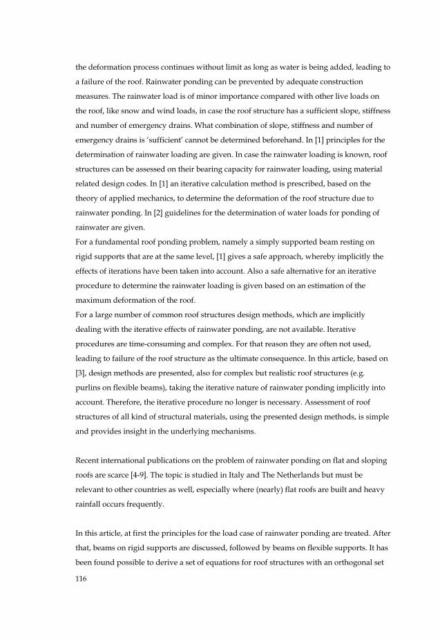
In [1] the principles for rainwater ponding are given as treated hereafter. Figure 1 shows
schematically a cross section over the roof edge. The emergency drain opening, with width
b and height h, is situated at a distance ndh over the roof. It is assumed that only a height
of ndd of the opening is used. The water level hwd at the roof edge then is:
ndndhw hdd += (1)
Other principles for the load case rainwater ponding are as follows:
• the load is bound to a location;
• water drainage through one or more regular water drains is not possible because of
obstruction;
• water drainage over the roof edge or through the opening of the emergency drain(s)
is possible.
EMERGENCY DRAIN
hwd ndhndd h
b
Figure 1: Roof edge with rainwater and emergency drain opening
According to [1], the rainwater load p is:
γ)( nhw ddp += (2)
in which:
γ density of water (10 kN/m3);
nd water level caused by the deformation of the roof structure by permanent load
118
and water ponding, determined with the iterative procedure of the code [1].
Hereafter, a number of common load cases on roof beams are analytically treated without
use of an iterative calculation method.
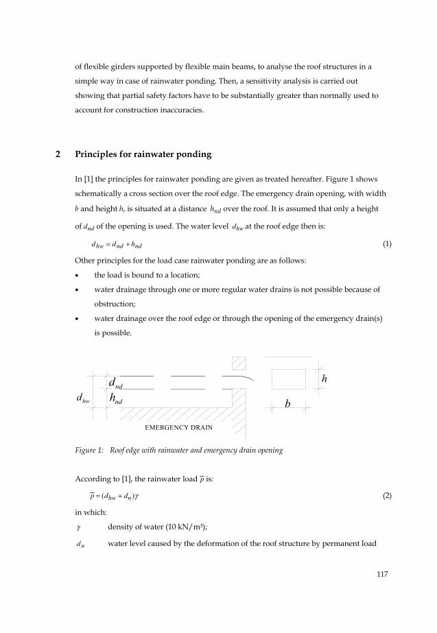
3 Beams on rigid supports
In case of beams rigidly supported at both ends, we can distinguish the following load
cases (Figure 2):
A. Uniformly distributed load;
B. Triangular load;
C. Trapezoidal load;
D. Partial triangular load.
Load case A is for a horizontal roof; the load cases B to D are for sloping roofs.
Figure 2: Load cases for rigid supported beams
The centre-to-centre distance of the beams is a, the bending stiffness is EI and the water
level over the not-deformed roof at the roof edge hwd .
3.1 Uniformly distributed load (load case A)
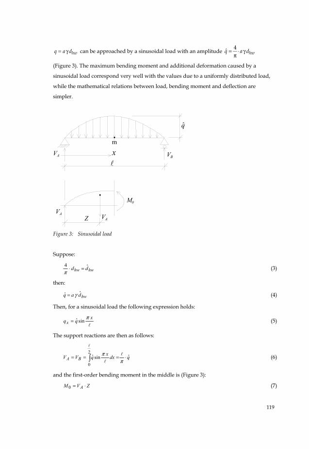
The first load case to be considered is a uniformly distributed load (Figure 2A). The
uniformly distributed load
A B
C D
119
hwq a d= γ can be approached by a sinusoidal load with an amplitude 4hwq̂ a d= ⋅ γ
π
(Figure 3). The maximum bending moment and additional deformation caused by a
sinusoidal load correspond very well with the values due to a uniformly distributed load,
while the mathematical relations between load, bending moment and deflection are
simpler.
q̂
xm
VA VB
VA VA
M0
Z
Figure 3: Sinusoidal load
Suppose:
hwhw dd ˆ4 =⋅π
(3)
then:
hwdaq ˆˆ γ= (4)
Then, for a sinusoidal load the following expression holds:
xqqxπsinˆ= (5)
The support reactions are then as follows:
qdxxqVV BA ˆsinˆ2
0⋅=== ∫ π
π (6)
and the first-order bending moment in the middle is (Figure 3):
ZVM A ⋅=0 (7)
120
It can be derived [3] that π/=Z , so that the bending moment in the middle is:
qZVM A ˆ2
20
π=⋅= (8)
This bending moment M0 corresponds very well with the bending moment as a result of a
uniformly distributed load q, since:
8752.74ˆ
22
2
2
2
20
qqqqM ≈=⋅==πππ
(9)
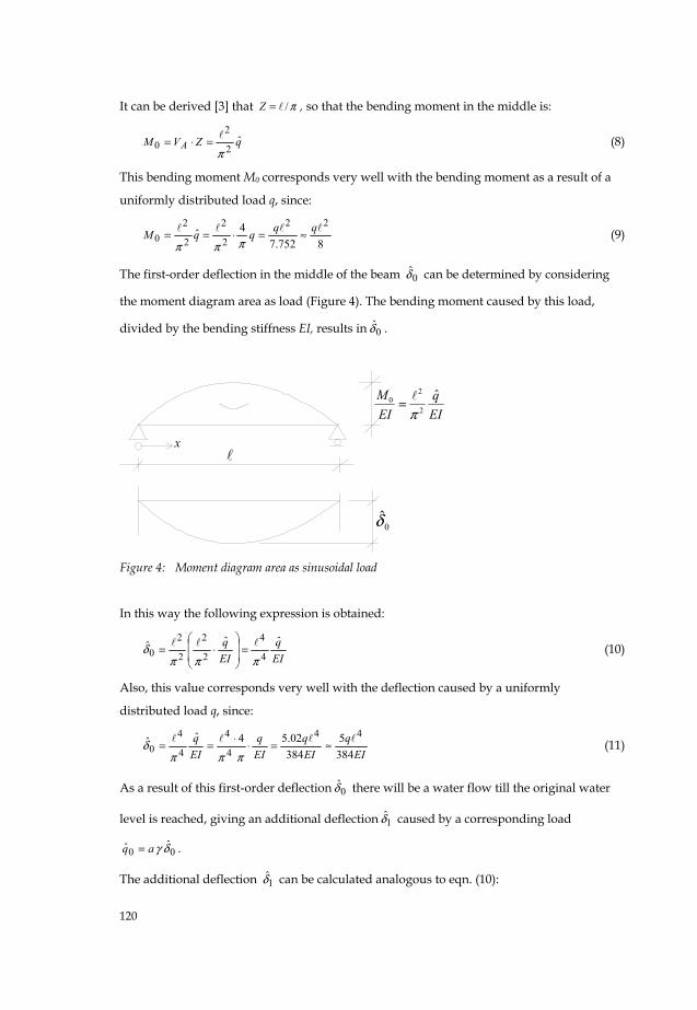
The first-order deflection in the middle of the beam 0δ̂ can be determined by considering
the moment diagram area as load (Figure 4). The bending moment caused by this load,
divided by the bending stiffness EI, results in 0δ̂ .
x
EIq
EIM ˆ
2
20
π=
0δ̂
Figure 4: Moment diagram area as sinusoidal load
In this way the following expression is obtained:
EIq
EIq ˆˆˆ
4
4
2
2
2
20
πππδ =
⎟⎟
⎠
⎞
⎜⎜
⎝
⎛⋅= (10)
Also, this value corresponds very well with the deflection caused by a uniformly
distributed load q, since:
EIq
EIq
EIq
EIq
3845
38402.54ˆˆ
44
4
4
4
40 ≈=⋅⋅==
πππδ (11)
As a result of this first-order deflection 0δ̂ there will be a water flow till the original water
level is reached, giving an additional deflection 1̂δ caused by a corresponding load
00ˆˆ δγaq = .
The additional deflection 1̂δ can be calculated analogous to eqn. (10):
121
EIda
EI
a
EI
a
EI
q hwˆˆˆˆ
44
44
40
4
40
41
γππ
γπ
δγπ
δ =⋅
== (12)
As a result of 1̂δ there will be an additional deflection 2δ̂ , etc.
The total deflection due to the water load endδ̂ is the sum .........ˆˆˆˆ210 δδδδ ++=end
or:
⎟⎟⎟
⎠
⎞
⎜⎜⎜
⎝
⎛+⎟
⎟
⎠
⎞
⎜⎜
⎝
⎛++×
⎟⎟
⎠
⎞
⎜⎜
⎝
⎛= ..................1
ˆˆ
2
4
4
4
4
4
4
EI
a
EI
aEIda hw
endπ
γπ
γγπ
δ (13)
If =EI
a4
4
πγ 1, than endδ̂ is just unlimited.
The corresponding value of the bending stiffness EI = 4
4
πγa is defined as the critical
bending stiffness EIcr:
4
4
πγa
EIcr = (14)
Suppose:
nEIEI
cr= (15)
then eqn. (13) can be rewritten as:
endδ̂ = ⎟⎟⎠
⎞⎜⎜⎝
⎛++ ..........111ˆ
20nn
δ (16)
Now, if:
11 <n
(17)
then:
endδ̂1
ˆ11
ˆ0
0−
⋅=−
=n
n
n
δδ (18)
With:
0δ̂n
dd
EIEI
EIda hw
hwcrhw
ˆˆ
ˆ
4
4=⋅==
γ
π (19)
it is found that:
1
ˆ
1ˆˆ0 −
=−
=nd
nn hw
end δδ (20)
122
The deflection in the middle of the beam can simply be calculated using hwd̂ and n.
A small value of n gives large deflections (and bending moments) and has to be avoided.
The water load endq̂ as a result of endδ̂ is enda δγ ˆ .
The increase of M0 is:
endend aqM δγππ
ˆˆ2
2
2
2==Δ (21)
so that:
MMM end Δ+= 0 (22)
3.2 Triangular load (load case B)
The next load case to be considered is a triangular load (Figure 2B). This load occurs in case
of a sloping roof. The results for load case B can be derived directly from those for load
case A. The deflection in the middle is (based on symmetry considerations) exactly half of
the deflection caused by a uniformly distributed load (load case A):
ndhw2
ˆˆ0 =δ (23)
and:
( )12
ˆ
12
ˆˆ
−=
−⋅=
nd
nn
nd hwhw
endδ (24)
3.3 Trapezoidal load (load case C)
The third load case to be considered is a trapezoidal load (Figures 2C and 5). Also this load
case can be derived from the previous cases, considering a trapezoidal load as the sum of a
uniformly distributed load and a triangular load [3], resulting in:
12
ˆˆˆ 21
−⎟⎟
⎠
⎞
⎜⎜
⎝
⎛+=
nn
nd
nd hwhw
endδ (25)
The first-order bending moment in the middle of the beam is then:
γπ
ad
dM hwhw ⎟
⎟
⎠
⎞
⎜⎜
⎝
⎛+=
2
ˆˆ 2
12
20 (26)
and the increase of the bending moment in the middle of the beam, respectively the
maximum bending moment in the beam, can again be determined with Eqns. (21) and (22)
respectively.
123
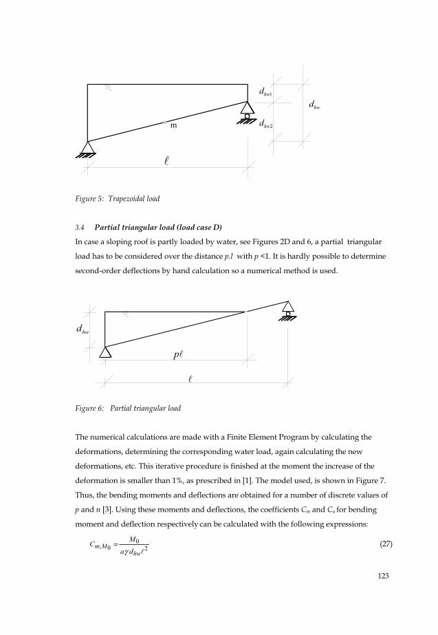
Figure 5: Trapezoidal load
3.4 Partial triangular load (load case D)
In case a sloping roof is partly loaded by water, see Figures 2D and 6, a partial triangular
load has to be considered over the distance p.l with p <1. It is hardly possible to determine
second-order deflections by hand calculation so a numerical method is used.
Figure 6: Partial triangular load
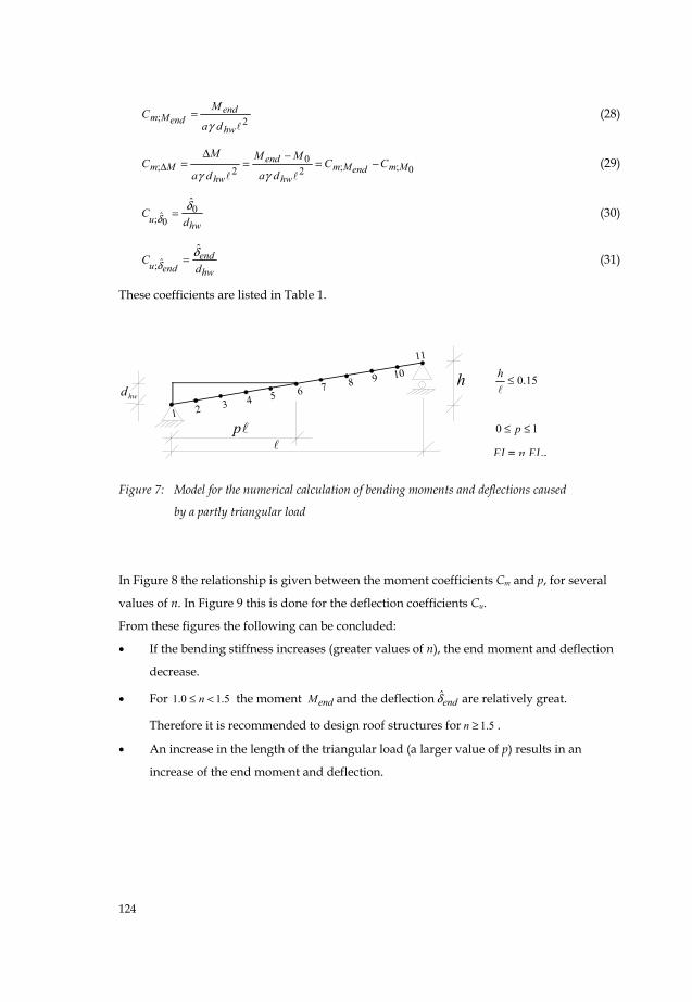
The numerical calculations are made with a Finite Element Program by calculating the
deformations, determining the corresponding water load, again calculating the new
deformations, etc. This iterative procedure is finished at the moment the increase of the
deformation is smaller than 1%, as prescribed in [1]. The model used, is shown in Figure 7.
Thus, the bending moments and deflections are obtained for a number of discrete values of
p and n [3]. Using these moments and deflections, the coefficients Cm and Cu for bending
moment and deflection respectively can be calculated with the following expressions:
20
0;hw
MmdaMC
γ= (27)
m
1hwd
2hwd
hwd
p
hwd
124
15.0≤h
10 ≤≤ p
EI = n EIcr
2;hw
endendMm
da
MC
γ= (28)
0;;20
2; MmendMmhw
end
hwMm CC
da
MM
da
MC −=
−=
Δ=Δ
γγ (29)
hwu dC 0
0ˆ;δ̂
δ = (30)
hwend
endu dC δ
δˆ
ˆ; = (31)
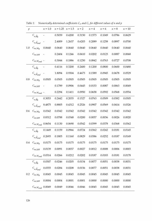
These coefficients are listed in Table 1.
Figure 7: Model for the numerical calculation of bending moments and deflections caused
by a partly triangular load
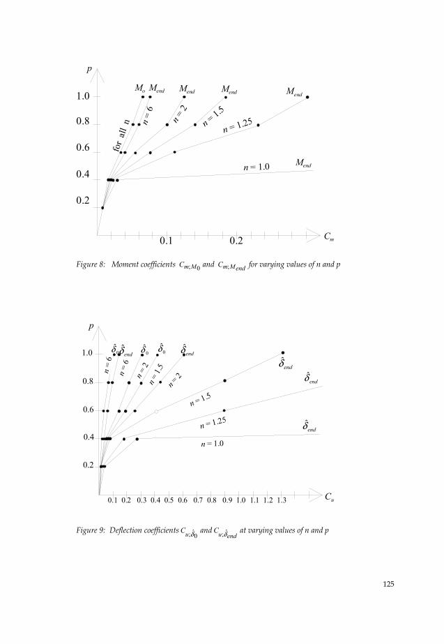
In Figure 8 the relationship is given between the moment coefficients Cm and p, for several
values of n. In Figure 9 this is done for the deflection coefficients Cu.
From these figures the following can be concluded:
• If the bending stiffness increases (greater values of n), the end moment and deflection
decrease.
• For 5.10.1 <≤ n the moment endM and the deflection endδ̂ are relatively great.
Therefore it is recommended to design roof structures for 5.1≥n .
• An increase in the length of the triangular load (a larger value of p) results in an
increase of the end moment and deflection.
1 2 3 4 5 6 7 8 9 10
11
hwd
p
h
125
1.0
0.8
0.6
0.4
0.2
0.1 0.2
Mo Mend Mend Mend
for
all
n n =
6
n = 2
n = 1.5
Cm
p
Mend
Mend
n = 1.25
n = 1.0
Figure 8: Moment coefficients 0;MmC and endMmC ; for varying values of n and p
n = 2
1.0
0.1 0.2 0.3 0.4 0.5 0.6 0.7 0.8 0.9 1.0 1.1 1.2 1.3 Cu
p
endδ̂0δ̂
endδ̂endδ̂0δ̂ 0δ̂
0.8
0.6
0.4
0.2
n = 2n
= 6
n = 1.
5n =
6
n = 1.5
n = 1.25
n = 1.0
endδ̂
endδ̂
Figure 9: Deflection coefficients0ˆ;δuC and
enduC δ̂; at varying values of n and p
126
Table 1: Numerically determined coefficients Cm and Cu for different values of n and p
p n = 1.0 n = 1.25 n = 1.5 n = 2 n = 4 n = 6 n = 8 n = 10
0ˆ;δuC - 0.5039 0.4200 0.3150 0.1573 0.1049 0.0786 0.0629
enduC δ̂; - 2.4009 1.2637 0.6203 0.2089 0.1258 0.0897 0.0700
0;MmC 0.0640 0.0640 0.0640 0.0640 0.0640 0.0640 0.0640 0.0640
MmC Δ; - 0.2404 0.1246 0.0610 0.0202 0.0123 0.0087 0.0068
1.0
endMmC ; - 0.3044 0.1886 0.1250 0.0842 0.0763 0.0727 0.0708
0ˆ;δuC - 0.4116 0.3200 0.2400 0.1200 0.0800 0.0600 0.0480
enduC δ̂; - 1.8094 0.9304 0.4673 0.1589 0.0945 0.0678 0.0529
0;MmC 0.0505 0.0505 0.0505 0.0505 0.0505 0.0505 0.0505 0.0505
MmC Δ; - 0.1789 0.0906 0.0445 0.0153 0.0087 0.0063 0.0049
0.8
endMmC ; - 0.2294 0.1411 0.0950 0.0658 0.0592 0.0568 0.0554
0ˆ;δuC 0.3053 0.2442 0.2035 0.1527 0.0763 0.0509 0.0382 0.0305
enduC δ̂; 8.4875 0.8805 0.4312 0.2526 0.0907 0.0569 0.0414 0.0326
0;MmC 0.0342 0.0342 0.0342 0.0342 0.0342 0.0342 0.0342 0.0342
MmC Δ; 0.8312 0.0788 0.0348 0.0200 0.0057 0.0036 0.0026 0.0020
0.6
endMmC ; 0.8654 0.1130 0.0690 0.0542 0.0399 0.0378 0.0368 0.0362
0ˆ;δuC 0.1449 0.1159 0.0966 0.0724 0.0362 0.0242 0.0181 0.0145
enduC δ̂; 0.2693 0.1805 0.1160 0.0829 0.0386 0.0252 0.0187 0.0149
0;MmC 0.0175 0.0175 0.0175 0.0175 0.0175 0.0175 0.0175 0.0175
MmC Δ; 0.0139 0.0091 0.0037 0.0027 0.0012 0.0008 0.0006 0.0003
0.4
endMmC ; 0.0314 0.0266 0.0212 0.0202 0.0187 0.0183 0.0181 0.0178
0ˆ;δuC 0.0307 0.0246 0.0205 0.0154 0.0077 0.0051 0.0038 0.0031
enduC δ̂; 0.0355 0.0284 0.0208 0.0156 0.0077 0.0051 0.0038 0.0031
0;MmC 0.0045 0.0045 0.0045 0.0045 0.0045 0.0045 0.0045 0.0045
MmC Δ; 0.0004 0.0004 0.0001 0.0001 0.0000 0.0000 0.0000 0.0000
0.2
endMmC ; 0.0049 0.0049 0.0046 0.0046 0.0045 0.0045 0.0045 0.0045
127
3.5 Examples for beams on rigid supports
Two examples are presented for the calculation method for rigidly supported beams under
rainwater loading.
For these examples, the following assumptions are made:
• The centre-to-centre distance of the roof beams a = 5 m.
• The beam span = 15 m.
• The load factors for dead load and live load are:
2.1; =dlfγ and 3.1; =llfγ respectively.
• Loads:
The dead load of the roof plates and insulation is 0.2 kN/m2.
The assumed dead load of the steel beam is 0.9 kN/m.
Then the dead load on the beam can be calculated as
9.19.02.05 =+⋅=repg kN/m.
The snow load is 0.7 kN/m2. With roof shape factor 0.8 this results in a snow load
prep;s = 8.27.08.05 =⋅⋅ kN/m on the beam.
The water load for dhw = 0.1m at the roof edge is:
5101.05; =⋅⋅=wrepp kN/m.
For combined dead load and snow load, the beam load is:
92.58.23.19.12.1; =⋅+⋅=sdq kN/m
For combined dead load and rainwater load, the beam load is:
78.853.19.12.1; =⋅+⋅=wdq kN/m
Since srepwrep pp ;; > the water load is decisive.
• With eqn. (14) the critical bending stiffness EIcr can be calculated:
25985151054
4
4
4=⋅⋅=⋅⋅=
ππγaEIcr kNm2.
• Now, the section profile is determined. It is advised to limit the additional
deformation addu of a roof e.g. by using the following requirement:
06.0004.0 =≤addu m which is based on [1]. The additional deformation addu is
defined as the deformation caused by the live load on a roof, in this case the water
load. Thus, the water load on the roof is kept within reasonable limits by designing a
relatively stiff roof structure.
With eqn. (20), n can be calculated to fulfil this requirement:
128
06.0004.0 =⋅≤=∧
endaddu δ m. Using eqn. (20) leads to:
11.0406.0
−⋅≥
nπand thus: 12.3≥n .
With 12.3≥=crEI
EIn the required bending stiffness can be calculated:
810732598512.3 =⋅>EI kNm2
A steel section IPE500 with 41048199 ⋅=I mm4 has sufficient bending stiffness:
945 101012181048199101.2 ⋅=⋅⋅⋅=EI Nmm2 = 101218 kNm2 > 80173 kNm2.
• For this section IPE500 the following can be calculated:
• the additional deformation due to water load 0.5; =wrepp kN/m is:
033.0101218
150.5384
5 4=⋅⋅=addu m
• the deformation due to dead load 9.1=repg kN/m can be calculated as:
012.0033.00.59.1 =⋅=dlu m
• The elastic moment capacity Mu for steel grade S235 can be calculated as:
63 10453235101928 ⋅=⋅⋅=uM Nmm = 453 kNm, with the elastic section modulus
of an IPE500 section being 3101928 ⋅=W mm3.
3.5.1 Example 1: Uniformly distributed load (load case A)
Using the assumptions and results of the previous paragraph, the following values have
been considered, for the uniformly distributed load case of Figure 10:
dhw = 0.1 m;
90.325985
101218 ===crEI
EIn
udl = 0.012 m;
a = 5 m;
= 15 m.
Equation (3), adding the deformation due to dead load, leads to:
139.0012.01.044ˆ =+=+⋅=ππ dlhwhw udd m
With Eqn. (20) it is found that:
129
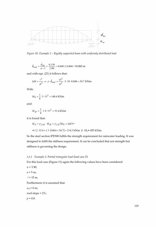
Figure 10: Example 1 – Rigidly supported beam with uniformly distributed load
004.0048.090.2
139.01
ˆˆ ≤==
−=
ndhw
endδ =0.060 m
and with eqn. (21) it follows that:
7.54048.010515ˆ2
2
2
2=⋅⋅⋅=⋅⋅⋅=Δ
πδγ
πendaM kNm
With:
6.14015581 2
0 =⋅⋅=M kNm
and:
4.53159.181 2 =⋅⋅=dlM kNm
it is found that:
( )MMMM llfdldlfd Δ++⋅= 0;; γγ =
= ( ) 3.2147.546.1403.14.532.1 =+⋅+⋅ kNm ≤ Mu= 453 kNm.
So the steel section IPE500 fulfils the strength requirement for rainwater loading. It was
designed to fulfil the stiffness requirement. It can be concluded that not strength but
stiffness is governing the design.
3.5.2 Example 2: Partial triangular load (load case D)
For this load case (Figure 11) again the following values have been considered:
n = 3.90;
a = 5 m;
= 15 m.
Furthermore it is assumed that:
udl = 0 m;
roof slope = 2%;
p = 0.8.
hwd
onu
130
hwd
8.0=p
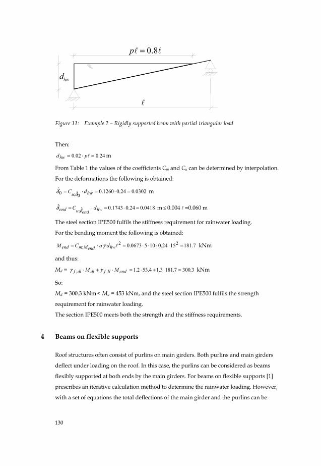
Figure 11: Example 2 – Rigidly supported beam with partial triangular load
Then:
24.002.0 =⋅= pdhw m
From Table 1 the values of the coefficients Cm and Cu can be determined by interpolation.
For the deformations the following is obtained:
0302.024.01260.0ˆ0̂;0 =⋅=⋅= hwu dC δδ m
0418.024.01743.0ˆ ˆ; =⋅=⋅= hwenduend dC δδ m ≤ 0.004 =0.060 m
The steel section IPE500 fulfils the stiffness requirement for rainwater loading.
For the bending moment the following is obtained:
7.1811524.01050673.0 22; =⋅⋅⋅⋅=⋅= hwendMmend daCM γ kNm
and thus:
Md = endllfdldlf MM ⋅+⋅ ;; γγ 3.3007.1813.14.532.1 =⋅+⋅= kNm
So:
Md = 300.3 kNm < Mu = 453 kNm, and the steel section IPE500 fulfils the strength
requirement for rainwater loading.
The section IPE500 meets both the strength and the stiffness requirements.
4 Beams on flexible supports
Roof structures often consist of purlins on main girders. Both purlins and main girders
deflect under loading on the roof. In this case, the purlins can be considered as beams
flexibly supported at both ends by the main girders. For beams on flexible supports [1]
prescribes an iterative calculation method to determine the rainwater loading. However,
with a set of equations the total deflections of the main girder and the purlins can be
131
calculated directly. This set of equations is derived in the next section. It is assumed that all
supports are in a horizontal plane.
4.1 Derivation of set of equations
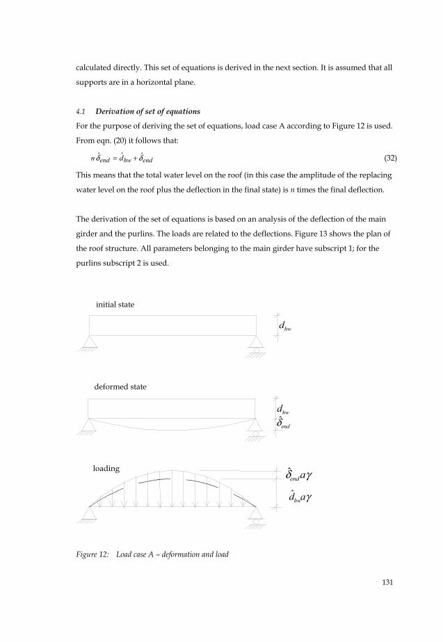
For the purpose of deriving the set of equations, load case A according to Figure 12 is used.
From eqn. (20) it follows that:
endhwend dn δδ ˆˆˆ += (32)
This means that the total water level on the roof (in this case the amplitude of the replacing
water level on the roof plus the deflection in the final state) is n times the final deflection.
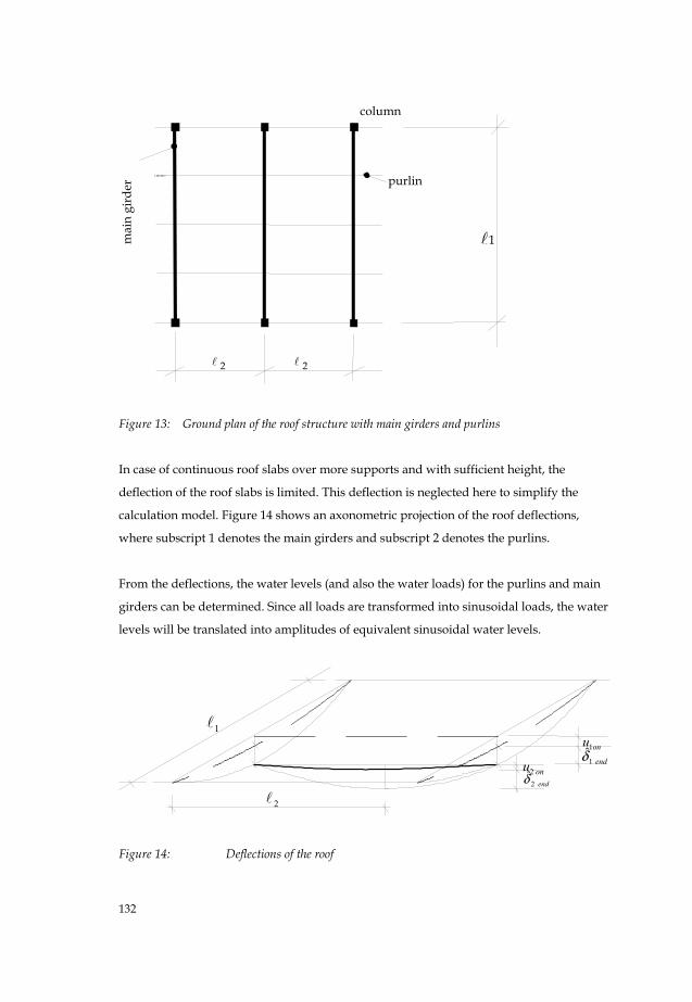
The derivation of the set of equations is based on an analysis of the deflection of the main
girder and the purlins. The loads are related to the deflections. Figure 13 shows the plan of
the roof structure. All parameters belonging to the main girder have subscript 1; for the
purlins subscript 2 is used.
hwdendδ̂
hwd
γadhwˆ
γδ aendˆ
deformed state
loading
initial state
Figure 12: Load case A – deformation and load
initial state
deformed state
loading
132
Figure 13: Ground plan of the roof structure with main girders and purlins
In case of continuous roof slabs over more supports and with sufficient height, the
deflection of the roof slabs is limited. This deflection is neglected here to simplify the
calculation model. Figure 14 shows an axonometric projection of the roof deflections,
where subscript 1 denotes the main girders and subscript 2 denotes the purlins.
From the deflections, the water levels (and also the water loads) for the purlins and main
girders can be determined. Since all loads are transformed into sinusoidal loads, the water
levels will be translated into amplitudes of equivalent sinusoidal water levels.
2
end2δ̂
onu1
onu2
1
end1̂δ
Figure 14: Deflections of the roof
mai
n gi
rder
2
column
purlin
2
1
133
end2δ̂
end1̂δ
onu2
hwd
hwd2ˆ
onu1
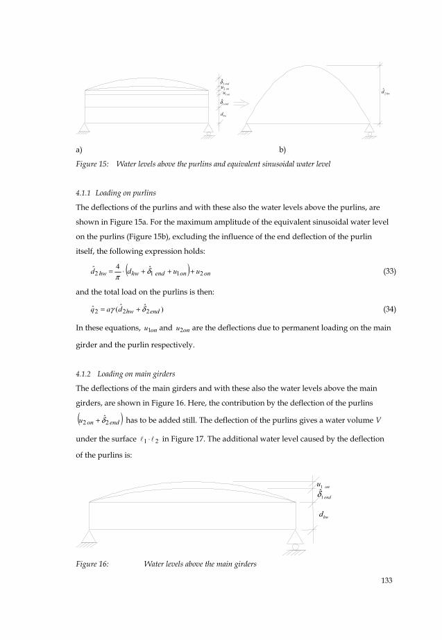
a) b)
Figure 15: Water levels above the purlins and equivalent sinusoidal water level
4.1.1 Loading on purlins
The deflections of the purlins and with these also the water levels above the purlins, are
shown in Figure 15a. For the maximum amplitude of the equivalent sinusoidal water level
on the purlins (Figure 15b), excluding the influence of the end deflection of the purlin
itself, the following expression holds:
( ) ononendhwhw uudd 2112ˆ4ˆ +++⋅= δ
π (33)
and the total load on the purlins is then:
)ˆˆ(ˆ 222 endhwdaq δγ += (34)
In these equations, onu1 and onu2 are the deflections due to permanent loading on the main
girder and the purlin respectively.
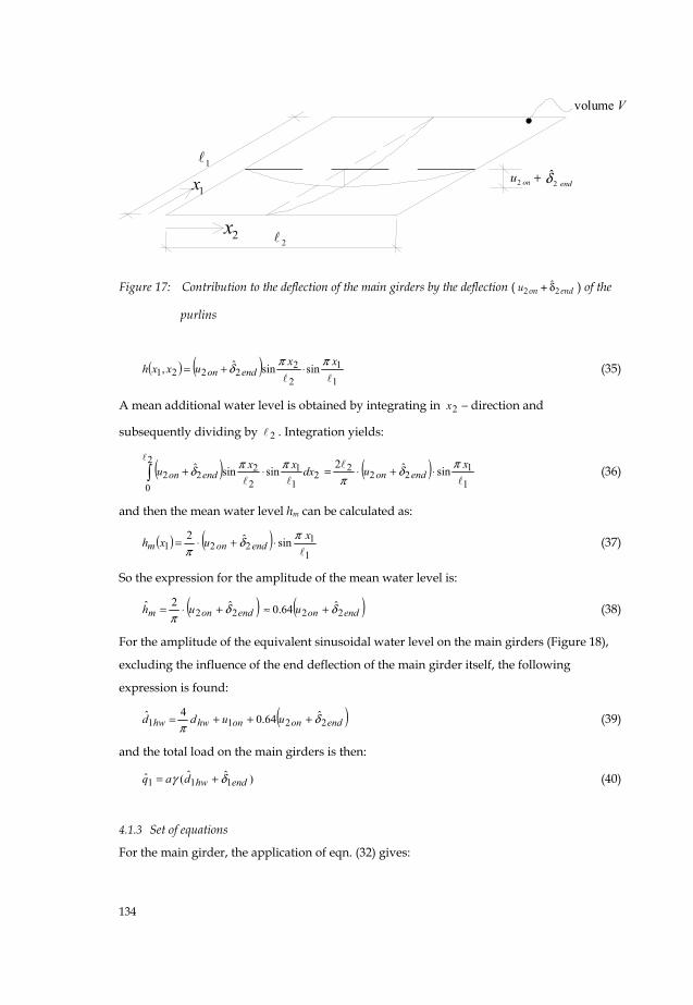
4.1.2 Loading on main girders
The deflections of the main girders and with these also the water levels above the main
girders, are shown in Figure 16. Here, the contribution by the deflection of the purlins
( )endonu 22 δ̂+ has to be added still. The deflection of the purlins gives a water volume V
under the surface 21 ⋅ in Figure 17. The additional water level caused by the deflection
of the purlins is:
end1̂δonu1
hwd
Figure 16: Water levels above the main girders
134
2
end2̂δ+onu2
1
1x
2x
volume V
Figure 17: Contribution to the deflection of the main girders by the deflection ( 2 2ˆ
on endu δ+ ) of the
purlins
( ) ( )1
1
2
22221 sinsinˆ,
xxuxxh endonππδ ⋅+= (35)
A mean additional water level is obtained by integrating in −2x direction and
subsequently dividing by 2 . Integration yields:
( ) 211
2
0 22
22 sinsinˆ dxxxu endonππδ ⋅+∫ ( )
1
122
2 sinˆ2 xu endonπδ
π⋅+⋅= (36)
and then the mean water level hm can be calculated as:
( ) ( )1
1221 sinˆ2 xuxh endonm
πδπ
⋅+⋅= (37)
So the expression for the amplitude of the mean water level is:
( )endonm uh 22ˆ2ˆ δ
π+⋅= ( )endonu 22
ˆ64.0 δ+≈ (38)
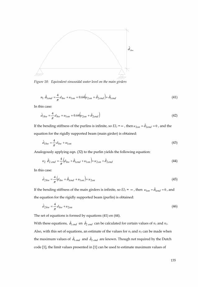
For the amplitude of the equivalent sinusoidal water level on the main girders (Figure 18),
excluding the influence of the end deflection of the main girder itself, the following
expression is found:
( )endononhwhw uudd 2211ˆ64.04ˆ δ
π+++= (39)
and the total load on the main girders is then:
)ˆˆ(ˆ 111 endhwdaq δγ += (40)
4.1.3 Set of equations
For the main girder, the application of eqn. (32) gives:
135
Figure 18: Equivalent sinusoidal water level on the main girders
( ) endendononhwend uudn 122111ˆˆ64.04ˆ δδ
πδ ++++= (41)
In this case:
( )endononhwhw uudd 2211ˆ64.04ˆ δ
π+++= (42)
If the bending stiffness of the purlins is infinite, so EI2 = ∞ , then 0ˆ22 == endonu δ , and the
equation for the rigidly supported beam (main girder) is obtained:
onhwhw udd 114ˆ +=π
(43)
Analogously applying eqn. (32) to the purlin yields the following equation:
( ) endononendhwend uudn 221122ˆˆ4ˆ δδ
πδ ++++= (44)
In this case:
( ) ononendhwhw uudd 2112ˆ4ˆ +++= δ
π (45)
If the bending stiffness of the main girders is infinite, so EI1 = ∞ , then 01̂1 == endonu δ , and
the equation for the rigidly supported beam (purlin) is obtained:
onhwhw udd 224ˆ +=π
(46)
The set of equations is formed by equations (41) en (44).
With these equations, end1̂δ en end2δ̂ can be calculated for certain values of n1 and n2.
Also, with this set of equations, an estimate of the values for n1 and n2 can be made when
the maximum values of end1̂δ and end2δ̂ are known. Though not required by the Dutch
code [1], the limit values presented in [1] can be used to estimate maximum values of
hwd1ˆ
136
end1̂δ and end2δ̂ . Thus, the water load on the roof is kept within reasonable limits by
designing a relatively stiff roof structure.
The application of this set of equations is illustrated in the example in the next section for
the design and calculation situation.
4.2 Example for beams on flexible supports
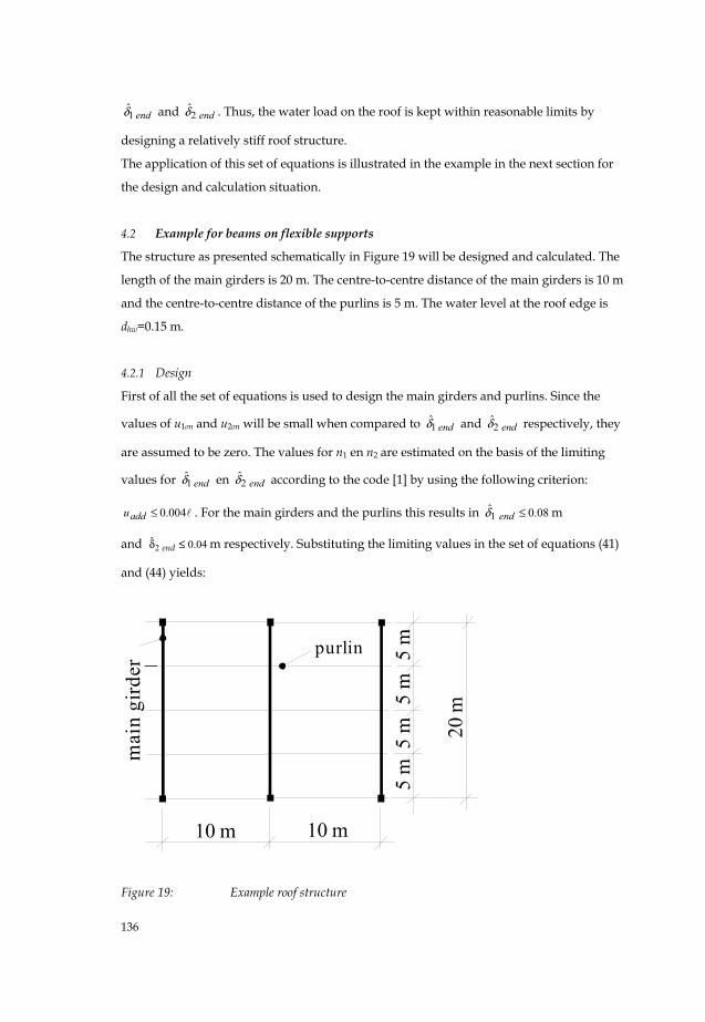
The structure as presented schematically in Figure 19 will be designed and calculated. The
length of the main girders is 20 m. The centre-to-centre distance of the main girders is 10 m
and the centre-to-centre distance of the purlins is 5 m. The water level at the roof edge is
dhw=0.15 m.
4.2.1 Design
First of all the set of equations is used to design the main girders and purlins. Since the
values of u1on and u2on will be small when compared to end1̂δ and end2δ̂ respectively, they
are assumed to be zero. The values for n1 en n2 are estimated on the basis of the limiting
values for end1̂δ en end2δ̂ according to the code [1] by using the following criterion:
004.0≤addu . For the main girders and the purlins this results in 08.01̂ ≤endδ m
and 2ˆ 0.04endδ ≤ m respectively. Substituting the limiting values in the set of equations (41)
and (44) yields:
mai
n gi
rder
purlin
10 m
20 m
5 m
10 m
5 m
5 m
5 m
Figure 19: Example roof structure
137
• with eqn. (41): 71.308.004.064.015.0408.0 11 =→+⋅+⋅=⋅ nnπ
;
• with eqn. (44): ( ) 32.804.008.015.0404.0 22 =→++⋅=⋅ nnπ
.
With eqn. (14) the critical bending stiffness of the main girders can be found:
1642562010104
4
4
41 =⋅⋅==
ππγaEI cr kNm2.
For the purlins this critical bending stiffness is:
5133101054
4
4
42 =⋅⋅==
ππγaEI cr kNm2.
With eqn. (15) the required bending stiffness of the main girders becomes:
60939016425671.3111 =⋅== crEInEI kNm2
and for the purlins:
42707513332.8222 =⋅== crEInEI kNm2
With 8101.2 ⋅=E kN/m2 for steel, the required moment of inertia for the main girders
is 41 100186.29 −⋅=I m4 and for the purlins 4
2 100337.2 −⋅=I m4.
Therefore, the following sections are chosen:
• main girders HE800A with moment of inertia 41 10344.30 −⋅=I m4, section
modulus 31 107680 ⋅=W mm3 and dead load 2.24 kN/m;
• purlins IPE400 with 42 10313.2 −⋅=I m4, 3
2 1160 10W = ⋅ mm3 and dead load 0.663
kN/m.
Thus, the sections have been designed with sufficient stiffness against ponding resulting in
values 5.1≥n . Now, their strength has to be checked. This is done in the next section.
4.2.2 Calculation
The set of equations (41) and (44) will now be used to calculate the roof structure of Figure
19. The main girders are HE800A sections with bending stiffness
63722410344.30101.2 481 =⋅×⋅= −EI kNm2 which yields:
88.31
11 ==
crEIEIn .
The purlins are IPE400 sections with bending stiffness 4857310313.2101.2 482 =⋅×⋅= −EI
kNm2 which yields:
138
46.92
22 ==
crEIEI
n .
Thus, the values for n1 and n2 in the set of equations are known. Now the values of u1on and
u2 on are determined. The dead load of the roof slabs including isolation and roofing is 0.2
kN/m2. For the dead load on main girders and purlins respectively, the following is
obtained:
566.55
10663.024.22.010;1 =⋅++⋅=repg kN/m
663.1663.02.05;2 =+⋅=repg kN/m
Then the deflections due to dead load can be calculated as:
0182.0637224
20566.5384
5 41 =⋅⋅=onu m
0045.048573
10663.1384
5 42 =⋅⋅=onu m
Substituting the results in the set of equations (41) and (44) results in:
88.3 ( ) endendend 121ˆˆ0045.064.00182.015.04ˆ δδ
πδ ++++⋅=
( ) endendend 212ˆ0045.00182.0ˆ15.04ˆ46.9 δδ
πδ ++++=
Solving this set of equations yields:
08212.01̂ =endδ m
03821.0ˆ2 =endδ m
Now, the maximum amplitude of the equivalent sinusoidal water level on the main girders
can be calculated with eqn. (41):
( ) endhwendendononhwend duudn 11122111ˆˆˆˆ64.04ˆ δδδ
πδ +=++++=
or
319.008212.088.3ˆˆˆ1111 =⋅==+ endendhw nd δδ m
The maximum amplitude of the equivalent sinusoidal water level on the purlins can be
calculated with eqn. (44):
361.003821.046.9ˆˆˆ2222 =⋅==+ endendhw nd δδ m
The bending moment in the main girders in the ultimate limit state is then:
1, 1, ; 1, ;d g f dl q f llM M Mγ γ= ⋅ + →
139
22 1
1, 1; 1 ; 1 1 ;21 ˆ ˆ( )8d rep f dl hw end f llM g a dγ γ δ γ
π= ⋅ ⋅ ⋅ + ⋅ + ⋅ →
22
1 21 205 566 20 1 2 10 10 0 319 1 38,dM . . . .
π= ⋅ ⋅ ⋅ + ⋅ ⋅ ⋅ ⋅ →
1 333 9 1680 7 2014 6,dM . . .= + = kNm
This bending moment results in the following elastic bending stress in the main girders:
262107680
106.20143
61 =
⋅
⋅=σ N/mm2 > fyd = 235 N/mm2
The bending moment in the purlins is:
2, 2, ; 2, ;d g f dl q f llM M Mγ γ= ⋅ + →
22 2
2, 2; 2 ; 2 2 ;21 ˆ ˆ( )8d rep f dl hw end f llM g a dγ γ δ γ
π= ⋅ ⋅ ⋅ + ⋅ + ⋅ →
22
2 21 101 663 10 1 2 5 10 0 361 1 38,dM . . . .
π= ⋅ ⋅ ⋅ + ⋅ ⋅ ⋅ ⋅ →
2 24 9 237 8 262 7,dM . . .= + = kNm
This bending moment results in the following elastic bending stress in the purlins:
226101160
107.2623
62 =
⋅
⋅=σ N/mm2 < fyd = 235 N/mm2
The bending stress in the main girders is greater than the yield stress which means that the
main girders are not strong enough in case of elastic design. This can be solved by either
allowing for plastic design or choosing a heavier section. The bending stresses in the
purlins are sufficiently low.
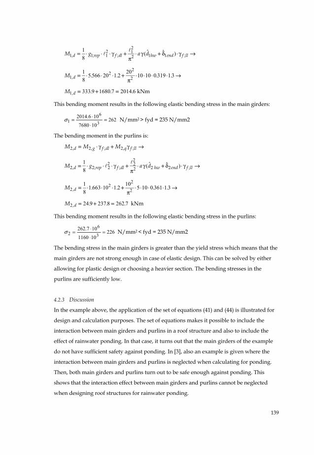
4.2.3 Discussion
In the example above, the application of the set of equations (41) and (44) is illustrated for
design and calculation purposes. The set of equations makes it possible to include the
interaction between main girders and purlins in a roof structure and also to include the
effect of rainwater ponding. In that case, it turns out that the main girders of the example
do not have sufficient safety against ponding. In [3], also an example is given where the
interaction between main girders and purlins is neglected when calculating for ponding.
Then, both main girders and purlins turn out to be safe enough against ponding. This
shows that the interaction effect between main girders and purlins cannot be neglected
when designing roof structures for rainwater ponding.
140
5 Sensitivity to construction inaccuracies
The height of the emergency drain opening has a strong influence on the water load: an
absolute small increase of the height dhw may give rise to failure. Moreover, the load case
may change with increasing height dhw from e.g. load case D to B to C (Figure 2). Also an
increase of water level caused by too little slope of the roof may have a strong influence. In
this section, a sensitivity analysis is carried out to find out the influence of design and
construction inaccuracies on ponding. This is done for relative simple load cases of rigidly
supported beams for variations in slope and height of the emergency drain.
5.1 Principles for the sensitivity analysis
The sensitivity analysis is limited to consequences of construction mistakes leading to
deviation of the design values for height of emergency drains and roof slope. It is assumed
that other deviations leading to other water loads are negligibly small and that no mistakes
in modelling and calculation have been made. For an assumed deviation, the increase of
the water load is determined, after which the load factor qf ;γ can be calculated necessary
to cover this load increase. Both flat roofs and sloping roofs are considered.
For flat and sloping roofs, the variation in height of the emergency drains hwdΔ is
considered. Two values for hwdΔ are chosen: 5% and 10% of hwd (see Figure 20). For an
emergency drain height between 50 and 200 mm, the absolute value of the deviation will
thus be between 2.5 and 20 mm.
For flat roofs the deviation from the horizontal level is considered, introducing an
adjusting error Δ for the level of the supports (see Figure 21).
For sloping roofs the deviation Δα related to the design value of the sloping angle α is
introduced (see Figure 24). ForααΔ two values are chosen:
51 and
101 .
If the geometry of the water load does not change, the quotient:
0
0
M MM
Δθ
+= (47)
is constant for a given value of n. The parameter θ is an amplification factor, equal to
1−nn , and thus a function of n.
141
For sloping roofs with a partial triangular load, with p < 1, at increase of the water level the
geometry of the load will change, so the quotient:
0
0
M MM
Δψ
+= (48)
for a given n is not constant, but depends on n and p (Table 2). For p = 1 it holds that:
ψ θ= .
5.2 Flat roofs
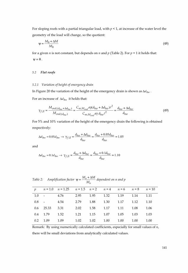
5.2.1 Variation of height of emergency drain
In Figure 20 the variation of the height of the emergency drain is shown as hwdΔ .
For an increase of hwdΔ it holds that:
2;( ) ;
; 2;( ) ;
( )hw hw end
hw end
end d d m M hw hw hw hwf ll
end d hwm M hw
M C a d d d dM dC a d
Δ γ Δ Δγ
γ+ + +
= = = (49)
For 5% and 10% variation of the height of the emergency drain the following is obtained
respectively:
→=Δ hwhw dd 05.0 ;0.05
1.05hw hw hw hwf ll
hw hw
d d d dd d
Δγ
+ += = =
and
→=Δ hwhw dd 1.0 ;0.1
1.10hw hw hw hwf ll
hw hw
d d d dd d
Δγ
+ += = =
Table 2: Amplification factor o
o
M MM
Δψ += dependent on n and p
p n = 1.0 n = 1.25 n = 1.5 n = 2 n = 4 n = 6 n = 8 n = 10
1.0 - 4.76 2.95 1.95 1.32 1.19 1.14 1.11
0.8 - 4.54 2.79 1.88 1.30 1.17 1.12 1.10
0.6 25.33 3.31 2.02 1.58 1.17 1.11 1.08 1.06
0.4 1.79 1.52 1.21 1.15 1.07 1.05 1.03 1.03
0.2 1.09 1.09 1.02 1.02 1.00 1.00 1.00 1.00
Remark: By using numerically calculated coefficients, especially for small values of n,
there will be small deviations from analytically calculated values.
142
Figure 20: Flat roof – variation of the height of the emergency drain hwdΔ
Thus, the larger the imperfection, the larger the load factor has to be to cover up the load
increase. In this case the required load factor is smaller than the load factor prescribed in
[1], being ; 1.3f llγ = , so variations in height of the emergency drains of 5% and 10% are
covered by the load factor of the code [1]. In the present case a variation of 30% will be
covered using a load factor of 1.3, assuming a correct modelling and calculation method.
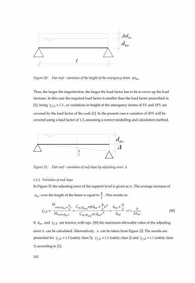
Figure 21: Flat roof – variation of roof slope by adjusting error Δ
5.2.2 Variation of roof slope
In Figure 21 the adjusting error of the support level is given as Δ . The average increase of
hwd over the length of the beam is equal to2Δ . This results in:
2
;( ) ;2; 2
;( ) ;
( )2 2hw end
hw end
end d m M hw hwf ll
end d hwm M hw
M C a d d
M dC a d
Δ Δ Δγγ
γ
+ + += = =
hwd21 Δ+= (50)
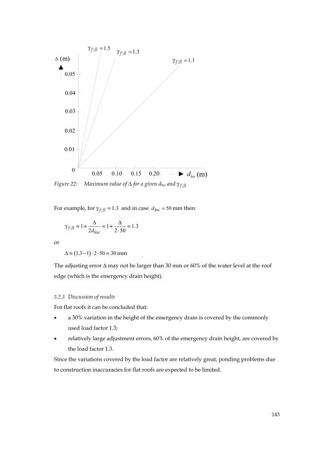
If hwd and ;f llγ are known, with eqn. (50) the maximum allowable value of the adjusting
error Δ can be calculated. Alternatively, Δ can be taken from Figure 22. The results are
presented for ; 1.5f llγ = (safety class 3), ; 1.3f llγ = (safety class 2) and ; 1.1f llγ = (safety class
1) according to [1].
Δhwd
2Δ
hwdhwdΔ
143
Figure 22: Maximum value of Δ for a given dhw and ;f llγ
For example, for ; 1.3f llγ = and in case 50=hwd mm then:
; 1 1 1.32 2 50f ll
hwdΔ Δ
γ = + = + =⋅
or
( )1 3 1 2 50 30.Δ = − ⋅ ⋅ = mm
The adjusting error Δ may not be larger than 30 mm or 60% of the water level at the roof
edge (which is the emergency drain height).
5.2.3 Discussion of results
For flat roofs it can be concluded that:
• a 30% variation in the height of the emergency drain is covered by the commonly
used load factor 1.3;
• relatively large adjustment errors, 60% of the emergency drain height, are covered by
the load factor 1.3.
Since the variations covered by the load factor are relatively great, ponding problems due
to construction inaccuracies for flat roofs are expected to be limited.
0.05
0.01
0
0.02
0.03
0.04
0.05 0.10 0.15 0.20
1.1; =qfγ
5.1; =qfγ 3.1; =qfγΔ
hwd (m)
(m);f llγ
;f llγ
;f llγ
144
5.3 Sloping roofs
5.3.1 Variation of height of the emergency drain
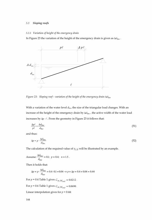
In Figure 23 the variation of the height of the emergency drain is given as hwdΔ .
Figure 23: Sloping roof – variation of the height of the emergency drain hwdΔ
With a variation of the water level dhw, the size of the triangular load changes. With an
increase of the height of the emergency drain by hwdΔ , the active width of the water load
increases by ⋅Δp . From the geometry in Figure 23 it follows that:
hwhw
dd
pp Δ=Δ (51)
and thus:
hw
hwdd
ppΔ
⋅=Δ (52)
The calculation of the required value of ;f llγ will be illustrated by an example.
Assume: 01 0 4 1 5hw
hw
d . ; p . ; n .d
Δ = = = .
Then it holds that:
0 4 01 0 04 0 4 0 04 0 44hw
hw
dp p . . . p p . . .d
ΔΔ Δ= ⋅ = ⋅ = → + = + =
For p = 0.4 Table 1 gives 0 0212endm;MC .= .
For p = 0.6 Table 1 gives 0 0690endm;MC .= .
Linear interpolation gives for p = 0.44:
hwd
hwdΔ
p pΔ
145
( ) 0308.00212.00690.02040212.0; =⎟
⎠
⎞⎜⎝
⎛ −+=endMmC
and thus:
)2;(
; 2;( )
0.0308 1,11.59
0.0212hw hw
hw
end d d hwf ll
end d hw
M a dM a d
Δ γγ
γ
+= = =
This result is shown in Table 3, indicated by the shaded area. More results are presented in
Table 3 for 5% and 10% variation in height of the emergency drains for different values of p
and n.
5.3.2 Variation in roof slope
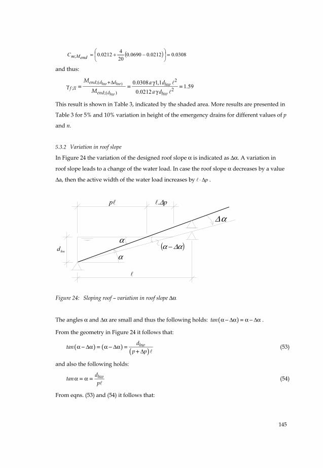
In Figure 24 the variation of the designed roof slope α is indicated as Δα. A variation in
roof slope leads to a change of the water load. In case the roof slope α decreases by a value
Δa, then the active width of the water load increases by pΔ⋅ .
Figure 24: Sloping roof – variation in roof slope Δα
The angles α and Δα are small and thus the following holds: ( )tan α Δα α Δα− = − .
From the geometry in Figure 24 it follows that:
( ) ( ) ( )hwdtan
p pα Δα α Δα
Δ− = − =
+ (53)
and also the following holds:
hwdtanp
α α= = (54)
From eqns. (53) and (54) it follows that:
hwd
pp Δ.
( )αΔα −α
αΔ
α
146
pp
ΔαΔ
α Δα⋅
=−
(55)
The value of ;f llγ can be calculated using Table 1. This calculation is illustrated by an
example again.
Assume: 0 02 0 002 1 5 0 4. ; . ; n . ; p .α Δα= = = =
Then the following holds:
Δαα
= 0.1, and
0 4 0 0020 044
0 02 0 002p . .p .
. .Δα
Δα Δα
⋅ ⋅= = = →
− −444.0044.04.0 =+=Δ+ pp
For p = 0.4 and n =1.5 Table 1 gives 0212.0; =endMmC .
For p = 0.44 and n =1.5 Table 1 gives 0308.0; =endMmC by interpolation.
And thus:
2;( ); 2
; ( )
0.03081.45
0.0212end hw
f llend hw
M a dM a d
α Δα
α
γγ
γ+= = =
This result is shown in Table 3, indicated by the shaded area. More results are presented in
Table 3 for Δαα
=51 and
101 for different values of p and n.
5.3.3 Simultaneously varying height of the emergency drain and roof slope
In Table 3, the required partial safety factors ;f llγ are also given to cover up for the
combined effect of a variation in sill height of 05.0/ =Δ hwhw dd and a variation in roof
slope of Δα/α = 0.10. These partial safety factors have been calculated in a similar way as
indicated above.
5.3.4 Discussion of results
Table 3 gives values for the partial safety factor ;f llγ necessary to cover up for construction
inaccuracies. According to [1], the partial safety factor is ; 1.3f llγ = for safety class 2, which
is valid for hall structures with flat roofs. So, for numbers in Table 3 smaller than 1.3, the
required safety level is assured and for numbers greater than 1.3, safety is insufficient. The
boundary value 1.3 is indicated in Table 3 by underlining the relevant numbers.
Considering the rows 2 and 3 in Table 3 for variation in height of the emergency drain, the
influence of n is relatively limited for those cases where 1 5n .≥ . For 1 5n .≥ and a variation
147
in sill height of 10%, the required partial safety factor exceeds 1.3 in many cases, so this
construction inaccuracy is unsafe, especially for small values of p. For a 5% variation in
height of the emergency drain, the required safety level is reached for 1 5n .≥ .
Considering the rows 4 and 5 in Table 3, then for 1 5n .≥ the variation in roof slope should
meet the requirement 010/ .Δα α ≤ to almost reach the required safety level corresponding
to ; 1.3f llγ = . However, even then there are cases ( 0 4p .≤ and 2n ≤ ) where the required
safety level is not reached. The influence of n is limited for those cases where 1 5n .≥ . A
greater inaccuracy in roof slope than 10% leads to required partial safety factors far greater
than 1.3.
Considering row 6 in Table 3 for the combined variation of sill height and roof slope
( 0 05hw hwd / d .Δ = and 010/ .Δα α = ), the required partial safety factor exceeds in many
cases 1.3. To cover up for these realistic construction inaccuracies a partial safety factor
; 1.8f llγ = is even necessary when n is limited to 1 5n .≥ . Again, for 1 5n .≥ the influence of
n is relatively small. However, for 1 5n .< the sensitivity to construction inaccuracies is
substantial in such a way that even a partial safety factor of 2.0 is insufficient. This being
impractical, it is suggested to limit n to 1 5n .≥ .
6 Conclusions
This article deals with the load case of rainwater ponding on roof structures consisting of
rigidly and flexibly supported beams. For rigidly supported beams, a number of load cases
are analysed. Also flexibly supported roof beams, namely purlins on main girders, are
analysed in this article. Calculation methods are given to design roof structures
considering water ponding, without the necessity to use a complex iterative analysis. For
roof structures consisting of purlins on main girders, a set of equations is derived which
enables the design and calculation for ponding of these structures.
Based on the calculations made and the sensitivity analyses for variations in height of the
emergency drain and/or in roof slope, the following conclusions can be drawn:
• The interaction between main girders and purlins always needs to be considered in
calculations. If not, the load case water ponding will be underestimated.
148
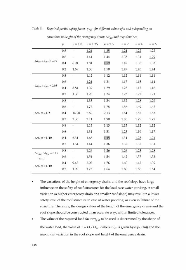
Table 3: Required partial safety factor ;f llγ for different values of n and p depending on
variations in height of the emergency drains hwdΔ and roof slope αΔ
p n = 1.0 n = 1.25 n = 1.5 n = 2 n = 4 n = 6
10.0/ =Δ hwhw dd
0.8
0.6
0.4
0.2
-
-
6.94
1.69
1.24
1.44
1.81
1.58
1.25
1.44
1.59
1.50
1.24
1.35
1.47
1.47
1.22
1.31
1.35
1.45
1.22
1.29
1.33
1.44
05.0/ =Δ hwhw dd
0.8
0.6
0.4
0.2
-
-
3.84
1.33
1.12
1.21
1.39
1.28
1.12
1.21
1.29
1.24
1.12
1.17
1.23
1.23
1.11
1.15
1.17
1.22
1.11
1.14
1.16
1.21
5/1/ =Δ αα
0.8
0.6
0.4
0.2
-
-
14.28
2.35
1.33
1.77
2.62
2.11
1.34
1.78
2.13
1.90
1.32
1.56
1.84
1.85
1.28
1.49
1.57
1.79
1.29
1.42
1.53
1.77
10/1/ =Δ αα
0.8
0.6
0.4
0.2
-
-
6.31
1.54
1.13
1.31
1.65
1.44
1.13
1.31
1.45
1.36
1.13
1.23
1.34
1.32
1.12
1.19
1.23
1.32
1.12
1.17
1.21
1.31
05.0/ =Δ hwhw dd and
10/1/ =Δ αα
0.8
0.6
0.4
0.2
-
-
9.43
1.90
1.26
1.54
2.07
1.75
1.26
1.54
1.76
1.64
1.26
1.42
1.60
1.60
1.23
1.37
1.42
1.56
1.28
1.33
1.39
1.54
• The variations of the height of emergency drains and the roof slope have large
influence on the safety of roof structures for the load case water ponding. A small
variation (a higher emergency drain or a smaller roof slope) may result in a lower
safety level of the roof structure in case of water ponding, or even in failure of the
structure. Therefore, the design values of the height of the emergency drains and the
roof slope should be constructed in an accurate way, within limited tolerances.
• The value of the required load factor ;f llγ to be used is determined by the shape of
the water load, the value of crn EI / EI= (where crEI is given by eqn. (14)) and the
maximum variation in the roof slope and height of the emergency drain.
149
• Based on the sensitivity analysis for flat roofs without slope, it can be concluded that
a variation in height of the emergency drains of 30% and an adjusting error of the
supports of 60% will be covered by a load factor ;f llγ =1.3 (relevant for industrial
halls [1]). So for flat roofs, problems caused by construction inaccuracies are normally
not to be expected.
• Based on the sensitivity analysis for sloping roofs with 1 5n .≥ it can be concluded that
a load factor ;f llγ = 1.8 should be used, while at the same time the variations of the
roof slope and the height of the emergency drains should be limited to 10% and 5%
respectively. If these tolerances are not feasible or if 1 5n .≥ , then a load factor even
greater than 1.8 is required.
• From the sensitivity analysis it appears that for sloping roofs with 1 5n .≥ the
influence of the value of n on the safety of the roof structure is small when compared
with the influence of construction inaccuracies and the influence of the area covered
with water.
• Especially flexible roofs (n < 1.5) are extremely sensitive to construction inaccuracies
regarding roof slope and height of emergency drains.
• Based on different considerations in this article and in [3] the authors advise to
design roof structures with a value 1 5n .≥ .
• Further research is recommended on the stochastic distribution of variations of the
height of emergency drains and roof slope, in practical situations. With help of these
figures and the accepted risks of failure, the required load factors can be calculated.
150
References
[1] NEN 6702, Loadings and deformations TGB 1990, NEN, Delft, The Netherlands (Dutch code).
[2] Nederlandse Praktijkrichtlijn (Dutch Guidelines for Practice) NPR 6703, Wateraccumulatie – Aanvullende rekenregels en vereenvoudigingen voor het belastinggeval regenwater in NEN6702 (Ponding on flat roofs caused by rainwater - Supplementary to NEN6702 with additional and simplified rules, in Dutch), NEN, Delft, The Netherlands, 2006
[3] Fijneman, H.J., Herwijnen, F. van, Snijder, H.H., (2003), Wateraccumulatie op daken (Water ponding on roofs, in Dutch), report O-2003.7, University of Technology Eindhoven, Department of Architecture, Building and Planning, Unit Structural Design and Construction Technology, december 2003 (in Dutch).
[4] Bontempi, F., Colombi, P., Urbano, C., Non-linear analysis of ponding effect on nearly flat roofs, Fifth Pacific Structural Steel Conference, eds. Chang et al., Seoul, 1998, pp. 1023-1028.
[5] Colombi, P., Urbano, C., Ponding effect on nearly flat roofs of industrial or commercial single story building, Proceedings of Eurosteel 1999, 2nd European Conference on Steel structures, Praha, Czech Republic, May 26-29, eds. J. Studnicka, F. Wald and J. Machacek (ISBN 80-01-01963-2), pp. 307-310.
[6] Urbano, C.A., Ponding effect on flat roofs, Structural Engineering International, IABSE, No. 1/2000, pp. 39-42.
[7] Snijder, H.H., Herwijnen, F.van, Fijneman, H.J., Sensitivity to ponding of roof structures under heavy rainfall, IABSE Symposium Lisbon 2005, Structures and Extreme Events, IABSE Report No. 90, pp. 190-191 and full 8 pages paper on CD.
[8] Colombi, P., The ponding problem on flat steel roof grids, Journal of Constructional Steel Research, Vol. 62, 2006, pp. 646-655.
[9] Blaauwendraad, J., Ponding on light-weight flat roofs: Strength and stability, Engineering Structures, Vol. 29, 2007, pp. 832-849.