Embed Size (px)
Citation preview
9StructuralControls

Cover photograph: Vegetated Swale, Southern River. (Source: Department of Water.)
Stormwater ManagementManual for Western Australia
9 Structural Controls
Department of Water and Swan River Trust Consultation and guidance from the Stormwater Working Team
May 2007

AcknowledgmentsThis chapter was written by Sasha Martens and Ross Perrigo, JDA Consultant Hydrologists, and Antonietta Torre, Lisa Chalmers, Emma Monk, Jason MacKay and Bill Till, Department of Water, and edited by Antonietta Torre and Emma Monk, Department of Water. The chapter was prepared with consultation and guidance from the Sub-team and the Stormwater Working Team. The initial draft of this chapter was prepared by Dan Luong, Marino Evangelisti, John Bronson and Ailan Tran, Parsons Brinckerhoff Australia Pty Ltd.
Sincere thanks to the Structural Controls Sub-team members and to the following people that provided considerable feedback and/or information for inclusion in the chapter: Michael Lindsay and Susan Harrington – Department of Health; Rachel Spencer, Debbie Besch and Peter Adkins – Swan River Trust; Simon Toze – CSIRO; Ron Van Delft – City of Armadale; Grahame Heal – City of Mandurah; Anthony McGrath – UDIA; Justine Lawn – Department of Environment and Conservation; David Kasehagen – Ecoscape; Daniel Skerratt – Ardross Group of Companies; Wayne Edgeloe – Thompson McRobert Edgeloe Pty Ltd; Graham Lantzke – Shire of Manjimup; Kym Hockley – Connell Wagner; Peter Pikor – (previously) City of Joondalup; Dave Mather – City of Joondalup; Melissa Bromly, Tarren Reitsema, Verity Klemm, Krish Seewraj, Naomi Hellriegel and Craig Tuesley – Department of Water.
Stormwater Working Team
Organisation RepresentativeConservation Council of Western Australia Mr Steven McKiernanDepartment for Planning and Infrastructure Ms Rachel DohertyDepartment of Environment and Conservation Ms Justine LawnDepartment of Health Dr Michael LindsayDepartment of Water Mr Greg DavisEastern Metropolitan Regional Council Ms Colleen MurphyEngineers Australia Mr Sasha MartensHousing Industry Association Ms Sheryl ChafferInstitute of Public Works Engineering Australia Mr Martyn GloverLandCorp Mr Bruce LowMain Roads Western Australia Mr Jerome GohSwan Catchment Council Ms Patricia PedeltySwan River Trust Ms Rachel SpencerUrban Development Institute of Australia Mr Anthony McGrathWater Corporation Mr Mark TontiWestern Australian Local Government Association Mr Michael Foley
Structural Controls Sub-team
Organisation RepresentativeDepartment of Environment and Conservation Dr Steve AppleyardDepartment of Environment and Conservation Mr Philip HineDepartment of Environment and Conservation Ms Justine LawnDepartment of Environment and Conservation Mr Stephen WongDepartment of Health Dr Michael LindsayDepartment of Water Ms Antonietta Torre
Department of Water Ms Lisa ChalmersDepartment of Water Mr Jason MacKayDepartment of Water Mr Mohammed BariDepartment of Water Mr Bill TillEastern Metropolitan Regional Council Mr Greg RyanEcological Engineering Pty Ltd Mr Andre TaylorEngineers Australia Mr Sasha MartensHousing Industry Association Ms Sheryl ChafferLandCorp Mr Bruce LowSwan River Trust Ms Rachel SpencerUrban Development Institute of Australia Mr Glenn HallWater Corporation Mr Michael ParkerWater Corporation Mr Mark TontiWestern Australian Local Government Association Mr Michael Foley
DisclaimerEvery effort has been taken by the authors and the sponsoring organisations to verify that the methods and recommendations contained in this manual are appropriate for Western Australian conditions. Notwithstanding these efforts, no warranty or guarantee, express, implied or statutory, is made as to the accuracy, reliability, suitability or results of the methods or recommendations.
The authors and sponsoring organisations shall have no liability or responsibility to the user or any other person or entity with respect to any liability, loss or damage caused or alleged to be caused, directly or indirectly, by the adoption and use of the methods and recommendations of the manual, including, but not limited to, any interruption of service, loss of business or anticipatory profits, or consequential damages resulting from the use of the manual. Use of the manual requires professional interpretation and judgement. Appropriate design procedures and assessment must be applied, to suit the particular circumstances under consideration.
Reference detailsThe recommended reference for this publication is:
Department of Water and Swan River Trust 2007, Structural controls, Stormwater Management Manual for Western Australia, Department of Water and Swan River Trust, Perth, Western Australia.
ISBN 1-92084-954-8 [Print – Manual]
May 2007
An electronic version of this chapter is available at <http://stormwater.water.wa.gov.au>.

THIS PAGE HAS BEEN LEFT BLANK INTENTIONALLY
Stormwater Management Manual for Western Australia: Structural Controls i
PrefaceA growing public awareness of environmental issues in recent times has elevated water issues to the forefront of public debate in Australia.
Stormwater is water flowing over ground surfaces and in natural streams and drains as a direct result of rainfall over a catchment (ARMCANZ and ANZECC, 2000).
Stormwater consists of rainfall runoff and any material (soluble or insoluble) mobilised in its path of flow. Stormwater management examines how these pollutants can best be managed from source to the receiving water bodies using the range of management practices available.
In Western Australia, where there is a superficial aquifer, drainage channels can commonly include both stormwater from surface runoff and groundwater that has been deliberately intercepted by drains installed to manage seasonal peak groundwater levels. Stormwater management is unique in Western Australia as both stormwater and groundwater may need to be managed concurrently.
Rainwater has the potential to recharge the superficial aquifer, either prior to runoff commencing or throughout the runoff’s journey in the catchment. Urban stormwater on the Swan Coastal Plain is an important source of recharge to shallow groundwater, which supports consumptive use and groundwater dependent ecosystems.
With urban, commercial or industrial development, the area of impervious surfaces within a catchment can increase dramatically. Densely developed inner urban areas are almost completely impervious, which means less infiltration, the potential for more local runoff and a greater risk of pollution. Loss of vegetation also reduces the amount of rainfall leaving the system through the evapo-transpiration process. Traditional drainage systems have been designed to minimise local flooding by providing quick conveyance for runoff to waterways or basins. However, this almost invariably has negative environmental effects.
This manual presents a new comprehensive approach to management of stormwater in WA, based on the principle that stormwater is a RESOURCE – with social, environmental and economic opportunities. The community’s current environmental awareness and recent water restrictions are influencing a change from stormwater being seen as a waste product with a cost, to a resource with a value. Stormwater Management aims to build on the traditional objective of local flood protection by having multiple outcomes, including improved water quality management, protecting ecosystems and providing livable and attractive communities.
This manual provides coordinated guidance to developers, environmental consultants, environmental/community groups, Industry, Local Government, water resource suppliers and State Government departments and agencies on current best management principles for stormwater management.
Production of this manual is part of the Western Australian Government’s response to the State Water Strategy (2003).
It is intended that the manual will undergo continuous development and review. As part of this process, any feedback on the series is welcomed and may be directed to the Drainage and Waterways Branch of the Department of Water.
ii Stormwater Management Manual for Western Australia: Structural Controls
Western Australian Stormwater Management Objectives
Water Quality To maintain or improve the surface and groundwater quality within the development areas relative to pre development conditions.
Water Quantity To maintain the total water cycle balance within development areas relative to the pre development conditions.
Water ConservationTo maximise the reuse of stormwater.
Ecosystem Health To retain natural drainage systems and protect ecosystem health .
Economic ViabilityTo implement stormwater management systems that are economically viable in the long term.
Public Health To minimise the public risk, including risk of injury or loss of life, to the community.
Protection of PropertyTo protect the built environment from flooding and waterlogging.
Social ValuesTo ensure that social, aesthetic and cultural values are recognised and maintained when managing stormwater.
DevelopmentTo ensure the delivery of best practice stormwater management through planning and development of high quality developed areas in accordance with sustainability and precautionary principles.
Western Australian Stormwater Management Principles• Incorporate water resource issues as early as possible in the land use planning process.
• Address water resource issues at the catchment and sub-catchment level.
• Ensure stormwater management is part of total water cycle and natural resource management.
• Define stormwater quality management objectives in relation to the sustainability of the receiving environment.
• Determine stormwater management objectives through adequate and appropriate community consultation and involvement.
• Ensure stormwater management planning is precautionary, recognises inter-generational equity, conservation of biodiversity and ecological integrity.
• Recognise stormwater as a valuable resource and ensure its protection, conservation and reuse.
• Recognise the need for site specific solutions and implement appropriate non-structural and structural solutions.
Stormwater Management Manual for Western Australia: Structural Controls iii
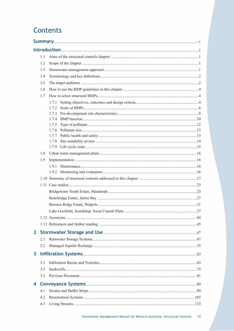
ContentsSummary ...................................................................................................................................................v
Introduction ............................................................................................................................................1
1.1 Aims of the structural controls chapter ..........................................................................................1
1.2 Scope of the chapter .......................................................................................................................1
1.3 Stormwater management approach ................................................................................................1
1.4 Terminologyandkeydefinitions ....................................................................................................2
1.5 The target audience ........................................................................................................................2
1.6 How to use the BMP guidelines in this chapter .............................................................................4
1.7 How to select structural BMPs .......................................................................................................4
1.7.1 Setting objectives, outcomes and design criteria ................................................................41.7.2 Scale of BMPs ....................................................................................................................61.7.3 Pre-development site characteristics ...................................................................................81.7.4 BMP function ....................................................................................................................101.7.5 Type of pollutant ...............................................................................................................121.7.6 Pollutant size .....................................................................................................................131.7.7 Public health and safety ....................................................................................................131.7.8 Site suitability review .......................................................................................................141.7.9 Life cycle costs .................................................................................................................15
1.8 Urban water management plans ...................................................................................................16
1.9 Implementation ............................................................................................................................16
1.9.1 Maintenance ......................................................................................................................161.9.2 Monitoring and evaluation ................................................................................................16
1.10 Summary of structural controls addressed in this chapter ...........................................................17
1.11 Case studies ..................................................................................................................................23
Bridgewater South Estate, Mandurah ..........................................................................................23
Beachridge Estate, Jurien Bay .....................................................................................................27
Boronia Ridge Estate, Walpole ....................................................................................................31
Lake Goollelal, Joondalup, Swan Coastal Plain ..........................................................................37
1.12 Acronyms .....................................................................................................................................44
1.13 References and further reading ....................................................................................................45
2 StormwaterStorageandUse ...............................................................................................47
2.1 Rainwater Storage Systems ..........................................................................................................47
2.2 Managed Aquifer Recharge..........................................................................................................55
3 InfiltrationSystems....................................................................................................................63
3.1 InfiltrationBasinsandTrenches ...................................................................................................63
3.2 Soakwells .....................................................................................................................................75
3.3 Pervious Pavement .......................................................................................................................81
4 ConveyanceSystems ................................................................................................................89
4.1 Swales and Buffer Strips ..............................................................................................................89
4.2 Bioretention Systems .................................................................................................................103
4.3 Living Streams ...........................................................................................................................123

iv Stormwater Management Manual for Western Australia: Structural Controls
5 DetentionSystems ...................................................................................................................137
5.1 Dry/Ephemeral Detention Areas ................................................................................................137
5.2 Constructed Wetlands .................................................................................................................145
6 PollutantControl .......................................................................................................................161
6.1 Litter and Sediment Management ..............................................................................................161
6.2 Hydrocarbon Management .........................................................................................................173
Stormwater Management Manual for Western Australia: Structural Controls v
SummaryThe aims of this chapter are to:
• Describe structural controls, as well as provide an overview of their benefits, use, effectiveness and evaluation.
• Provide basic information on the selection of structural controls and the use of relevant technical guidelines.
• Provide technical guidelines on some of the most relevant structural controls that can be applied at regional, estate and allotment scales in Western Australia.
Structural controls are engineered devices implemented to manage runoff quality and quantity, to control, treat or prevent stormwater pollution and/or reduce the volume of stormwater requiring management. Structural controls may be located at-source, in-transit or at end-of-catchment. They are ideally installed at or near the source of stormwater runoff, to protect receiving environments, including groundwater, waterways and wetlands. The implementation of structural stormwater best management practices into an urban landform has multiple benefits, including reducing storm flows, reducing pollutant export, maintaining and improving the urban landscape, protecting receiving environments and reducing irrigation and potable water supply requirements.
Structural controls can be designed for a new development on a greenfield or brownfield site, as well as retrofitting within existing developed areas. They should be used in combination with non-structural controls (i.e. the ‘treatment train approach’) to achieve a balanced mix of stormwater management measures.
This chapter aids in the selection, location and design of the most appropriate structural controls based on current understanding of the performance of structural controls and assessing the controls in the context of Western Australia’s local hydrology.
This chapter aims to ensure stormwater best management practices are implemented in a consistent manner and are achieving the objectives previously determined for a catchment through appropriate urban water management planning processes.
Table 1 on page 3 highlights the relevance for application by the target audiences of each of the structural controls that are addressed in this chapter. The structural control selection process is illustrated in the flow chart in Figure 1 on page 5 and discussed in the remainder of Section 1.7. A summary of each structural control addressed in this chapter is provided in Section 1.10.

vi Stormwater Management Manual for Western Australia: Structural Controls
THIS PAGE HAS BEEN LEFT BLANK INTENTIONALLY
Stormwater Management Manual for Western Australia: Structural Controls �
� Introduction
�.� Aims of the structural controls chapter
The aims of this chapter are to:
• Describe structural controls, as well as provide an overview of their benefits, use, effectiveness and evaluation.
• Provide basic information on the selection of structural controls and the use of relevant technical guidelines.
• Provide technical guidelines on some of the most relevant structural controls that can be applied at regional, estate and allotment scales in Western Australia.
It should be noted that the chapter does not seek to address all possible structural controls for stormwater management, but focuses on those currently recommended for use and generally supported in Western Australia by government agencies, and those which represent emerging technology considered suitable for application in Western Australia.
�.2 Scope of the chapter
This chapter focuses on the most relevant structural stormwater controls that can be used in Western Australia to manage the quantity and quality of stormwater runoff, prevent or treat stormwater pollution, and provide opportunities for water conservation through the use of stormwater as a resource.
This chapter aids in the selection, location and design of the most appropriate structural controls based on current understanding of the performance of structural controls and assessing the controls in the context of WA’s local hydrology.
This chapter aims to ensure stormwater best management practices (BMPs) are implemented in a consistent manner and are achieving the objectives previously determined for a catchment through appropriate urban water management planning processes.
Structural controls can be designed for a new development on a greenfield or brownfield site, as well as retrofitting within existing developed areas. Chapter 6 contains more information on retrofitting.
Non-structural controls are addressed in Chapter 7.
�.3 Stormwater management approach
This manual encourages a treatment train approach to stormwater management, where combinations of measures (structural and non-structural) are implemented in parallel or sequence to achieve best management of stormwater.
The implementation of structural stormwater BMPs into an urban landform has multiple benefits, including reducing storm flows, reducing pollutant export, maintaining and improving the urban landscape, protecting receiving environments and reducing irrigation and potable water supply requirements.
Chapter 2 of the manual recommends the following stormwater management approach in Western Australia:
2 Stormwater Management Manual for Western Australia: Structural Controls
1. Retain and restore natural drainage lines: retain and restore existing valuable elements of the natural drainage system, including waterway, wetland and groundwater features and processes.
2. Implement non-structural source controls: minimise pollutant inputs principally via planning, organisational and behavioural techniques, to minimise the amount of pollution entering the drainage system.
3. Minimise runoff: infiltrate or reuse rainfall as high in the catchment as possible. Install structural controls at or near the source to minimise pollutant inputs and the volume of stormwater.
4. Use in-system management measures: includes vegetative measures, such as swales and riparian zones, and structural quality improvement devices such as gross pollutant traps.
BMPs presented in this chapter address measures 1, 3, and 4 of this approach.
�.4 Terminology and key definitions
Structural stormwater best management practices are engineered devices implemented to manage runoff quality and quantity, to control, treat or prevent stormwater pollution and/or reduce the volume of stormwater requiring management. Structural controls may be located at-source, in-transit or at end-of-catchment. They are ideally installed at or near the source of stormwater runoff, to protect receiving environments, including groundwater, waterways and wetlands.
Source controls are structural or non-structural best management practices designed to minimise the generation of excessive stormwater runoff and/or pollution of stormwater at or near the source (New South Wales Environmental Protection Authority 1998) and protect receiving environments, including groundwater, waterways and wetlands.
Non-structural stormwater best management practices are institutional and pollution-prevention practices designed to prevent or minimise pollutants from entering stormwater runoff and/or reduce the volume of stormwater requiring management (United States Environmental Protection Agency 1999). They do not involve fixed, permanent facilities and they usually work by changing behaviour through government regulation (e.g. planning and environmental laws), education and/or economic instruments (Taylor & Wong 2002).
Receiving environments are areas that receive stormwater runoff, including wetlands, waterways, coastal waters/dunes, groundwater and bushland areas.
Water bodies are waterways, wetlands, coastal marine areas and shallow groundwater aquifers.
Effective imperviousness is the combined effect of the proportion of constructed impervious surfaces in the catchment, and the connectivity of these impervious surfaces to receiving water bodies.
A detailed glossary at the end of the manual provides definitions of technical terminology used in this chapter.
�.5 The target audience
This chapter is primarily aimed at engineers and other urban water management professionals and local and State government approval officers.
Due to the range of multi-disciplinary professionals usually involved in urban development and catchment management, it is also an information source for planners, urban designers, landscape architects, environmental scientists, landcare and community groups, developers and individual landowners.
Stormwater Management Manual for Western Australia: Structural Controls 3
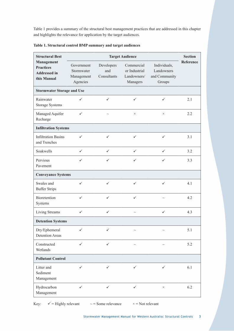
Table 1 provides a summary of the structural best management practices that are addressed in this chapter and highlights the relevance for application by the target audiences.
Table 1. Structural control BMP summary and target audiences
Structural Best Management Practices Addressed in this Manual
Target Audience Section Reference
Government Stormwater
Management Agencies
Developers and
Consultants
Commercial or Industrial Landowners/
Managers
Individuals, Landowners
and Community Groups
Stormwater Storage and Use
Rainwater Storage Systems
2.1
Managed Aquifer Recharge
~ × × 2.2
Infiltration Systems
Infiltration Basins and Trenches
3.1
Soakwells 3.2
Pervious Pavement
3.3
Conveyance Systems
Swales and Buffer Strips
4.1
Bioretention Systems
~ 4.2
Living Streams ~ 4.3
Detention Systems
Dry/Ephemeral Detention Areas
~ ~ 5.1
Constructed Wetlands
~ ~ 5.2
Pollutant Control
Litter and Sediment Management
6.1
Hydrocarbon Management
× 6.2
Key: = Highly relevant ~ = Some relevance × = Not relevant
4 Stormwater Management Manual for Western Australia: Structural Controls
�.6 How to use the BMP guidelines in this chapter
Structural controls should be selected according to the BMP selection process outlined in Section 1.7.
The BMPs in Sections 2 to 6 of this chapter contain summarised background information, recommended practices, factors to consider, cost details, performance indicators, local application examples and references for a number of structural controls.
It is not necessary to read all of the information in Sections 2 to 6 in order to use this chapter. The detailed content should be selectively accessed as needed, to gather information on how to select and apply specific structural controls.
The dollar values quoted in this chapter relating to BMP costs have not been adjusted for inflation or potential cost reductions due to technological advances which may have occurred since reference document publishing. Costs presented in this document should therefore be considered indicative only and users of the manual are encouraged to seek further specific industry advice on BMP costs as appropriate.
�.7 How to select structural BMPs
The selection of structural BMPs requires consideration of multiple factors, such as catchment management objectives, site characteristics, target pollutants, social values, and capital and operating costs to achieve a balance between quantity and quality management objectives and to create a sustainable outcome.
All BMPs, whether they are structural, non-structural, at-source, in-transit or end-of-catchment, have potential benefits and limitations. The key is finding the best combination of these measures to suit local circumstances.
Performance of structural BMPs largely depends on the pre-development (pre-implementation) site characteristics and scale in which the measures are to be implemented. Structural controls are designed to achieve pollutant removal (quality), volume management (quantity) and/or water conservation functions.
The approach adopted in the selection process recommends that these factors be examined before the assessment of BMP characteristics and functionalities.
A key decision for BMP selection is the life cycle cost (capital and maintenance costs). This will require a balance between outcomes sought and available funding.
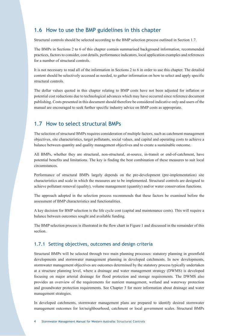
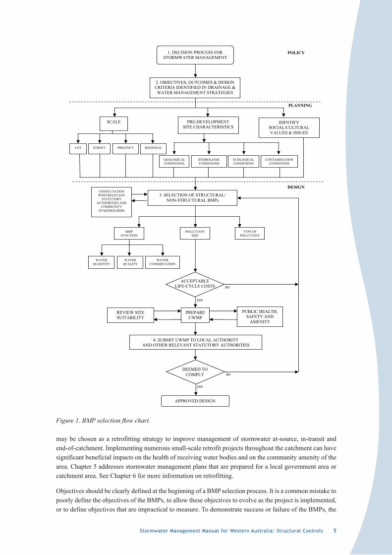
The BMP selection process is illustrated in the flow chart in Figure 1 and discussed in the remainder of this section.
�.7.� Setting objectives, outcomes and design criteria
Structural BMPs will be selected through two main planning processes: statutory planning in greenfield developments and stormwater management planning in developed catchments. In new developments, stormwater management objectives are outcomes determined by the statutory process typically undertaken at a structure planning level, where a drainage and water management strategy (DWMS) is developed focusing on major arterial drainage for flood protection and storage requirements. The DWMS also provides an overview of the requirements for nutrient management, wetland and waterway protection and groundwater protection requirements. See Chapter 3 for more information about drainage and water management strategies.
In developed catchments, stormwater management plans are prepared to identify desired stormwater management outcomes for lot/neighbourhood, catchment or local government scales. Structural BMPs
Stormwater Management Manual for Western Australia: Structural Controls 5
1. DECISION PROCESS FOR STORMWATER MANAGEMENT
POLICY
2. OBJECTIVES, OUTCOMES & DESIGNCRITERIA IDENTIFIED IN DRAINAGE &
WATER MANAGEMENT STRATEGIES
3. SELECTION OF STRUCTURAL/ CONSULTATIONWITH RELEVANT
STATUTORYAUTHORITIES AND
COMMUNITYSTAKEHOLDERS
NON-STRUCTURAL BMPs
BMPFUNCTION
POLLUTANTSIZE
TYPE OF POLLUTANT
WATERQUANTITY
WATERQUALITY
WATERCONSERVATION
ACCEPTABLELIFE-CYCLE COSTS
PREPAREUWMP
REVIEW SITE SUITABILITY
PUBLIC HEALTH, SAFETY AND
AMENITY
4. SUBMIT UWMP TO LOCAL AUTHORITY AND OTHER RELEVANT STATUTORY AUTHORITIES
DEEMED TO COMPLY
APPROVED DESIGN
SCALE
LOT STREET PRECINCT REGIONAL
GEOLOGICALCONDITIONS
HYDROLOGICCONDITIONS
ECOLOGICALCONDITIONS
CONTAMINATIONCONDITIONS
PRE-DEVELOPMENTSITE CHARACTERISTICS
DESIGN
PLANNING
IDENTIFYSOCIAL/CULTURALVALUES & ISSUES
no
yes
yes
no
Figure 1. BMP selection flow chart.
may be chosen as a retrofitting strategy to improve management of stormwater at-source, in-transit and end-of-catchment. Implementing numerous small-scale retrofit projects throughout the catchment can have significant beneficial impacts on the health of receiving water bodies and on the community amenity of the area. Chapter 5 addresses stormwater management plans that are prepared for a local government area or catchment area. See Chapter 6 for more information on retrofitting.
Objectives should be clearly defined at the beginning of a BMP selection process. It is a common mistake to poorly define the objectives of the BMPs, to allow these objectives to evolve as the project is implemented, or to define objectives that are impractical to measure. To demonstrate success or failure of the BMPs, the

6 Stormwater Management Manual for Western Australia: Structural Controls
objectives should be specific, measurable, achievable, relevant and linked to a timeframe. See Chapter 10 for further information on performance monitoring and evaluation.
The BMP selection process discussed in Section 1.7 is reliant on the establishment of water quantity and quality objectives in the DWMS process for greenfield developments. In established areas, water quantity and quality objectives are defined through natural resource management strategies, catchment management plans and stormwater management plans.
The main water sensitive design approaches discussed in the remainder of this section must be factored into the selection of structural controls.
Natural drainage systems should be protected, and constructed stormwater systems should mimic natural drainage processes. Water sensitive urban design includes maintenance of the pre-development hydrologic regime; that is, maintenance of the pre-development stormwater quantity characteristics. This includes retaining/detaining small – moderate rainfall events throughout the catchment, as close to the runoff source (i.e. the impervious surface) as possible.
Water sensitive urban design increases disconnection between impervious surfaces and receiving water bodies. As a general rule, stormwater should not be discharged directly into receiving water bodies and only moderate – large rainfall events should reach receiving water bodies via overland flow paths across vegetated surfaces.
Stormwater management systems should be incorporated throughout a catchment and integrated in the urban landscape, such as within road reserves and public open space. This will minimise the social and economic issues associated with allocating (and often fencing off) large areas of land for traditional devices such as steep sided trapezoidal open drains and large sumps. As shown in Figure 1, social/cultural values and issues should be identified during the planning stage of the BMP selection process and relevant statutory authorities and community stakeholders should be consulted during the BMP design stage of the selection process.
These approaches result in improved biodiversity and health of receiving water bodies and improved amenity and quality of urban areas.
�.7.2 Scale of BMPs
Scale refers to the intended location and ownership of structural BMPs. Four broad scales have been identified for the purpose of this manual. They include:
• lot level• street level• precinct level • regional level
BMP selection is best achieved using an integrated approach that focuses on meeting the overall objectives as set in the DWMS, catchment management plan or stormwater management plan. This typically requires the implementation of a treatment train approach across more than one scale. For example, a soakwell infiltration BMP may be proposed at a lot scale to complement the vegetated swale BMP at a street scale and the infiltration basin BMP at a precinct scale. This arrangement will satisfy the water quantity and quality objectives that might be unachievable if relying on a single BMP. Additionally, the impact from the failure of one device (e.g. flooding or water quality issues) will be reduced by the operation of the other devices in the treatment train.
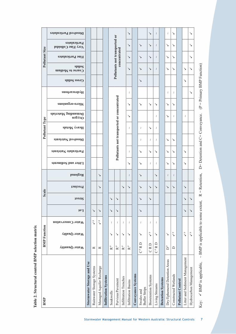
The suitability of structural control BMPs applied to different scales can be assessed using the selection matrix in Table 2.
Stormwater Management Manual for Western Australia: Structural Controls 7
Tabl
e 2.
Str
uctu
ral c
ontr
ol B
MP
sele
ctio
n m
atri
x
BM
PB
MP
Func
tion
Scal
ePo
lluta
nt T
ype
Pollu
tant
Siz
e
Water Quantity
Water Quality
Water Conservation
Lot
Street
Precinct
Regional
Litter and Sediments
Particulate Nutrients
Dissolved Nutrients
Heavy Metals
Oxygen Demanding Materials
Micro-organisms
Hydrocarbons
Gross Solids
Coarse to Medium Solids
Fine Particulates
Very Fine Colloidal Particulates
Dissolved Particulates
Stor
mw
ater
Sto
rage
and
Use
Rai
nwat
er S
tora
ge S
yste
ms
R
P
Man
aged
Aqu
ifer R
echa
rge
R
P
Infil
trat
ion
Syst
ems
Soak
wel
lsR
P
~
Pollu
tant
s not
tran
spor
ted
or c
once
ntra
ted
Pollu
tant
s not
tran
spor
ted
or
conc
entr
ated
Perv
ious
Pav
emen
tR
P
~
Infil
tratio
n Tr
ench
esR
P
~
Infil
tratio
n B
asin
sR
P
~
~
~~
~
Con
veya
nce
Syst
ems
Swal
es a
nd
Buf
fer S
trips
C P R
D
~
~
~
Bio
rete
ntio
n Sy
stem
sC
R D
P
~
~
~
Livi
ng S
tream
sC
P R
D
~
~
~
~~
~
~~
~
Det
entio
n Sy
stem
sD
ry/E
phem
eral
Det
entio
n A
reas
D P
~
~
~
Con
stru
cted
Wet
land
sD
P
~
~
~
Pollu
tant
Con
trol
Litte
r and
Sed
imen
t Man
agem
ent
P
~
Hyd
roca
rbon
Man
agem
ent
P
Key
:
BM
P is
app
licab
le,
~ B
MP
is a
pplic
able
to so
me
exte
nt,
R =
Ret
entio
n,
D=
Det
entio
n an
d C
= C
onve
yanc
e.
(P =
Prim
ary
BM
P Fu
nctio
n)
� Stormwater Management Manual for Western Australia: Structural Controls
�.7.3 Pre-development site characteristics
Detailed knowledge of the pre-development site characteristics is critical in the selection of BMPs, and the following characteristics can often dictate what structural control BMPs may or may not be effectively used at a particular site.
Geological conditions
The geotechnical and hydrogeological site assessment principally aims to determine the site constraints and the suitability of potential BMPs.
Soil permeability is a significant factor in selecting suitable devices. On-site hydraulic conductivity tests should be conducted due to the differences in permeability through the vertical and horizontal soil profiles.
Hydrologic conditions
The hydrologic conditions of a catchment include the relationships between rainfall, runoff, infiltration and evaporation. Water sensitive urban design can maintain a catchment’s hydrology by mimicking the natural hydrologic characteristics (volume, frequency, recharge and discharge). These characteristics are in balance with the unique soils, vegetation and topographic features of the catchment and should where possible be maintained to maximise the protection of receiving environments.
Natural surface to groundwater separation is another important issue to consider when selecting BMPs. Infiltration BMPs typically require some separation to deliver desired hydraulic performance and to allow treatment to be carried out as stormwater percolates through the soil. However, site modification using permeable fill may provide sufficient separation for the implementation of infiltration BMPs under certain circumstances. Also, due to the seasonal variability in groundwater levels in sandy soils, the separation distance may only be limited for part of the year and may not necessarily preclude the selection of a particular BMP. The water table is likely to be at the annual maximum groundwater level for only a short duration throughout the year. Performance may not need to be optimal year round. For example, in the south-west of the State, a stormwater management system may perform as a retention/detention system for the majority of storm events, particularly in summer, autumn and early winter (when groundwater levels are at their lowest and pollutants carried by stormwater are usually at their highest), but act primarily as a conveyance system for the short duration that the groundwater is at its maximum level in late winter and spring each year, when pollutants carried by stormwater are usually at their lowest.
An indication of groundwater levels can be obtained from the Department of Water’s Water Information Network (WIN) database or the Department of Water’s Perth Groundwater Atlas. However, site specific groundwater monitoring programs should be undertaken to determine the actual groundwater regime at a proposed development site.
Ecological conditions
Protection and enhancement of the natural site attributes should be maximised when selecting and locating BMPs. There are generally more opportunities for this in greenfield developments; however, protection of remnant environments is important in both greenfield and brownfield developments.
Landform and ecological surveys of local significant vegetation, waterways and wetlands should be conducted during pre-design work. A good understanding of the existing hydrology, water quality and ecological structure and interactions is required for setting objectives. Assessments should also consider the impacts of BMPs on the ecological system, such as permanently altering groundwater levels in natural wetlands.
Stormwater Management Manual for Western Australia: Structural Controls 9
Opportunities for retaining natural overland flow pathways should be identified as part of the assessment. The rehabilitation of degraded waterways can provide significant economic advantages in stormwater management, particularly due to their conveyance and water quality improvement functions and the improvement of aesthetic values within the development.
Contamination conditions
Historical land use
Historical land uses can cause soil and groundwater contamination. With urbanisation, it is important to manage stormwater quantity at-source so that there is less risk of these contaminants being potentially mobilised. BMP selection offers an opportunity to target specific contaminants or hot spots for treatment. In extreme cases, site remediation may be required for the complete removal of these contaminant sources.
Acid sulphate soils
Acid sulphate soils (ASS) form when soils naturally containing sulphide minerals are oxidised, forming sulphuric acid. Oxidation can occur when soils are exposed to the air following excavation or draining, or lowering water tables. Large-scale drainage for flood mitigation, urban expansion and agriculture has exposed many areas of acid sulphate soils in WA.
The acidic leachate and the metals consequently released from the exposed or drained soils cause significant environmental problems such as poor water quality and fish kills, as well as economic costs to communities through degradation of roads and corrosion of pipes and footings.
There are also public health risks associated with ASS via exposure to dissolved acids in water. These risks include potential for consumption, or skin and eye irritation from contact with acidic water.
ASS risk areas for parts of Western Australia can be viewed at the Department of Environment and Conservation website (<http://www.environment.wa.gov.au>).
Guidelines for managing ASS are contained in Department of Environment (2003).
Secondary salinity
Catchments with secondary salinity require urban stormwater management systems to be designed and managed to meet the outcomes of the local salinity management strategy. Issues such as exposing saline subsoils through cut and fill, increasing the regional groundwater level, changes to soil groundwater flow and disturbance to sensitive areas such as riparian corridors are some of the issues that will need to be considered when selecting structural BMPs.
Safeguarding Indigenous heritage
In addition to the physical site characteristics, it is recommended that stormwater managers and designers investigate other land issues that may impact on the implementation of BMPs.
Under the Aboriginal Heritage Act 1972, landowners have an obligation to determine if any Indigenous heritage sites may be affected by any proposed development or constructed infrastructure. If there is a possibility of affecting Indigenous heritage sites, the proponent must abide by the provisions of the Aboriginal Heritage Act 1972, as administered by the Department of Indigenous Affairs.
More detailed information on Indigenous values can be found in Chapters 5 and 6. Contact the Indigenous Support Unit at the Department of Water to find local Indigenous contacts.
�0 Stormwater Management Manual for Western Australia: Structural Controls
Protecting social values
It is important to ensure that social values (including cultural values) are taken into account. Social values embrace qualities for which a place has become a focus of spiritual, political, national or other cultural sentiment to a minority or majority group. Cultural significance includes aesthetic, historic, scientific or social values for past, present or future generations.
For example, a site (e.g. a park), natural feature (e.g. a water body, tree or rock formation) or structure (e.g. a weir) might have significant social/cultural values and will therefore require consideration in the selection and/or siting of a particular structural BMP.
As shown in Figure 1, consultation with the community to determine social/cultural values and issues is an essential component of BMP selection and design.
�.7.4 BMP function
Urban runoff has the potential to have a significant impact on the ecology of water bodies due to altered water regimes (volume, energy, frequency and timing of runoff) and poor water quality. Urban stormwater management BMPs can employ achieve key functions:
• Stormwater quantity management• Stormwater quality management • Water conservation
A structural control will have single or multiple functions that will help contribute to the overall objectives or outcomes established in the catchment management plan, stormwater management plan or urban water management plan for the area. Typically, a combination of structural and non-structural controls will be implemented in series or concurrently, forming a treatment train to help achieve an overall outcome (Chapter 4).
Stormwater quantity management
Stormwater quantity management recognises that urbanisation will typically lead to an increase in imperviousness and a corresponding increase in volume and rate of runoff.
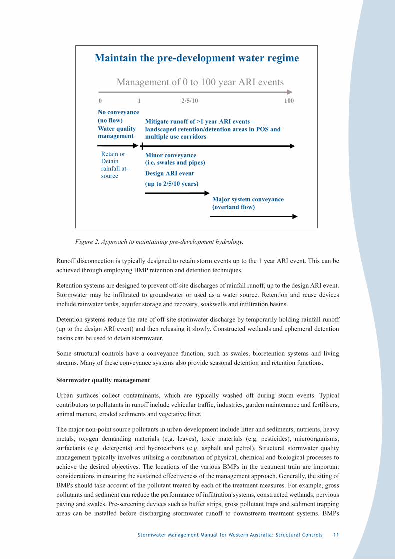
The sustainable approach to urban water management emphasises replicating post-development hydrology as close to pre-development conditions as possible (National Water Quality Management Strategy, ARMCANZ & ANZECC 2000). Figure 2 illustrates this recommended approach in relation to managing runoff from various design storm events.
Techniques that can be incorporated to maintain the pre-development hydrology through effectively minimising the ‘effective imperviousness’ of a development area include:
• reducing the amount of constructed impervious areas; and• disconnecting constructed impervious areas from receiving water bodies.
Reducing the amount of constructed imperviousness in a development area can be achieved through the application of alternative surfaces with lower runoff coefficients, such as permeable pavement, and through the retention of pervious areas, such as native vegetation, garden beds and parkland. This will reduce peak discharge, particularly for smaller storm events such as the 1 year average recurrence interval (ARI) event.
Direct connection of impervious areas to receiving water bodies results in altered hydrologic regimes with associated erosion, loss of habitat, and the efficient delivery of pollutants (Walsh et al. 2004). Disconnecting impervious areas from receiving water bodies helps to maintain the pre-development hydrologic regime.
Stormwater Management Manual for Western Australia: Structural Controls ��
Maintain the pre-development water regime
Management of 0 to 100 year ARI events
0 1 2/5/10 100
No conveyance(no flow)Water qualitymanagement
Minor conveyance(i.e.. swales and pipes)
Design ARI event(up to 2/5/10 years)
Major system conveyance(overland flow)
Mitigate runoff of >1 year ARI events –landscaped retention/detention areas in POS andmultiple use corridors
Retain orDetainrainfall at-source
Figure 2. Approach to maintaining pre-development hydrology.
Runoff disconnection is typically designed to retain storm events up to the 1 year ARI event. This can be achieved through employing BMP retention and detention techniques.
Retention systems are designed to prevent off-site discharges of rainfall runoff, up to the design ARI event. Stormwater may be infiltrated to groundwater or used as a water source. Retention and reuse devices include rainwater tanks, aquifer storage and recovery, soakwells and infiltration basins.
Detention systems reduce the rate of off-site stormwater discharge by temporarily holding rainfall runoff (up to the design ARI event) and then releasing it slowly. Constructed wetlands and ephemeral detention basins can be used to detain stormwater.
Some structural controls have a conveyance function, such as swales, bioretention systems and living streams. Many of these conveyance systems also provide seasonal detention and retention functions.
Stormwater quality management
Urban surfaces collect contaminants, which are typically washed off during storm events. Typical contributors to pollutants in runoff include vehicular traffic, industries, garden maintenance and fertilisers, animal manure, eroded sediments and vegetative litter.
The major non-point source pollutants in urban development include litter and sediments, nutrients, heavy metals, oxygen demanding materials (e.g. leaves), toxic materials (e.g. pesticides), microorganisms, surfactants (e.g. detergents) and hydrocarbons (e.g. asphalt and petrol). Structural stormwater quality management typically involves utilising a combination of physical, chemical and biological processes to achieve the desired objectives. The locations of the various BMPs in the treatment train are important considerations in ensuring the sustained effectiveness of the management approach. Generally, the siting of BMPs should take account of the pollutant treated by each of the treatment measures. For example, gross pollutants and sediment can reduce the performance of infiltration systems, constructed wetlands, pervious paving and swales. Pre-screening devices such as buffer strips, gross pollutant traps and sediment trapping areas can be installed before discharging stormwater runoff to downstream treatment systems. BMPs
�2 Stormwater Management Manual for Western Australia: Structural Controls
to remove types of pollutants are shown in Table 2. Sections 1.7.5 and 1.7.6 discuss pollutant removal further.
Designers are encouraged to infiltrate at-source as many rainwater events as possible, where site conditions allow, to increase disconnection and therefore reduce the collection and transportation of pollutants to receiving water bodies. Site investigations should be undertaken to select appropriate infiltration BMPs (as shown in Figure 1). Development should not result in deterioration of water quality in receiving water bodies, including mobilisation of existing contaminants. For example, it would usually be unsuitable to install an infiltration system up-gradient of a plume of contaminated groundwater. Infiltration systems are generally designed to maintain the pre-development site hydrologic regime, so there should be no increase in the amount of groundwater recharge compared to pre-development conditions. However, management of some contaminated sites might require that there be no groundwater recharge up-gradient of the contamination plume.
It should be noted that the most effective stormwater quality management programs use non-structural BMPs to complement the selected structural BMPs. For example, gross pollutants can be managed through implementing improved site management practices, litter bin provision, street sweeping, litter collection, vegetation selection and maintenance and regulation practices. See Chapter 7 for information on the selection and design of non-structural controls to reduce pollutant sources.
Water conservation
Water sensitive urban design and total water cycle management view stormwater as a resource, and options for collecting and using stormwater for irrigation and non-potable water supply are now being examined in Western Australia.
The reduction in rainfall in the south-west of Western Australia since 1975 and population growth resulting in increased demand throughout most of Western Australia has necessitated the investigation of alternative water sources. A number of structural (such as stormwater harvesting and rainwater tanks) and non-structural (such as ‘fit for purpose’ use of water) initiatives are being examined.
In considering stormwater conservation and reuse opportunities, it should be noted that stormwater is also an important source of water for maintaining the condition and function of natural wetlands and waterways, and providing for ecological water requirements.
�.7.5 Type of pollutant
An urban catchment is usually made up of multiple land uses (current and historical), which largely determine the stormwater pollutant profile of the catchment. For example, gross pollutants are prevalent in commercial areas, whereas sediments and nutrients are typically more prevalent in developing urban areas. Therefore, the promotion of at-source treatment targeting specific pollutants within the sub-catchment provides a far more efficient approach to stormwater management. Additionally, at-source use or infiltration of stormwater minimises the collection and downstream transportation of pollutants. See Chapter 2 (Section 3.1) for information on pollutants and their environmental impacts.
To effectively manage stormwater, it is necessary to match the selected BMPs with the site characteristics, including target pollutants and their transport pathways, groundwater levels and water quality of the receiving water body. For this selection to be successful, the designer needs to know about the catchment (land use, current stormwater management practices, soil types, hydrology, and groundwater interactions) and its pollutants (typical components, dominant transport pathways). If one of the objectives of the project is to improve water quality, it is essential that the water quality of the stormwater is known (or estimated), as this will influence the choice of BMPs.
Stormwater Management Manual for Western Australia: Structural Controls �3
Different processes are required for removing different pollutants and their components. If litter is a large problem (i.e. from high traffic or commercial areas), then an at-source gross pollutant trap (GPT) may be useful. If high concentrations of hydrocarbons from street runoff are expected, then an oil and grit trap may be the best solution. Stormwater with a high amount of sediment or nutrients attached to sediment can be treated by using retention/detention areas. Stormwater with a high amount of dissolved nutrients can be treated with BMPs that encourage biofilm growth, such as bioretention systems and constructed wetlands.
BMPs for the treatment of pollutant types can be assessed using the selection matrix in Table 2.
�.7.6 Pollutant size
Treatment of stormwater pollutants usually requires the reduction of one or more of the following pollutant sizes:
• gross solids: contaminants larger than 5 mm, such as litter and organic material;
• coarse to medium solids: contaminant particles between 5 mm and 0.125 mm;
• fine particulates: contaminant particles between 0.125 mm and 0.010 mm;
• very fine colloidal particulates: contaminants between 0.010 mm and 0.00045 mm. These contaminants, specifically nutrients, heavy metals, toxicants and hydrocarbons, attach themselves to fine sediments;
• dissolved particulates: contaminants less than 0.00045 mm. Dissolved contaminants include nutrients, metals and salts.
BMPs for the treatment of pollutants of various sizes can be assessed using the selection matrix in Table 2.
�.7.7 Public health and safety
Mosquito and midge management
Structural stormwater management systems should be carefully designed to minimise the risk of chironomid midge and mosquito breeding. These insects cause significant nuisance, affecting lifestyle and amenity and have direct and indirect economic impacts. Some mosquito species that breed in these environments can also be vectors of Ross River virus and other mosquito-borne diseases. Ideally, all components of a stormwater treatment train should be designed to ensure that they do not contribute to or create an environment that increases the opportunity for nuisance or disease vector species breeding on-site. At-source infiltration, ephemeral detention areas, overland flow paths over vegetated surfaces (swales) and living streams are preferred stormwater management options as they minimise the creation of areas of stagnant water.
An overall mosquito and chironomid midge risk and management program will need to be undertaken as part of the overall pre-implementation planning for a development area. There are three stages involved in developing a mosquito management program:
• Stage 1 – Establish a mosquito monitoring program to identify existing levels of mosquito activity, species diversity and density, and public health risks, prior to any ground disturbance. This needs to be conducted at appropriate times of the year and when environmental conditions are favourable for mosquito breeding. Ideally, such baseline surveys should include more than one ‘mosquito season’ to allow for substantial inter-annual variation in mosquito activity.
• Stage 2 – Design the stormwater management system to ensure that constructed waterway and wetland areas, multiple use corridors, road gullies (etc.) do not contribute to on-site mosquito breeding. For
�4 Stormwater Management Manual for Western Australia: Structural Controls
example, infiltration, evapotranspiration or drawing down of the water to prevent pooling for longer than four days will prevent completion of the aquatic (larval) stages of the mosquito life cycle. The four day guideline applies during the warmest months (e.g. late spring, summer and early autumn) in the south-west of WA and throughout the year in the north, as larval mosquitoes develop more rapidly in warmer temperatures. Contact the relevant local government Environmental Health Officer or the Mosquito-Borne Disease Control Branch of Department of Health for information about mosquito breeding risk seasons in different regions in WA. Other more intensive and expensive management approaches will be necessary in areas where infiltration/evapotranspiration of stormwater cannot be achieved within four days during risk times, either due to an impermeable substrate, a high groundwater table, existence of permanent water (e.g. in rainwater tanks and some constructed wetlands) or other factors. See individual BMPs for guidance on how to reduce mosquito breeding risk in these situations.
• Stage 3 – Ongoing inspection, maintenance and management of the stormwater system to ensure that it continues to operate as designed, thereby reducing the risk of conditions likely to promote on-site mosquito breeding.
For detailed advice on reducing the risk of mosquitoes, see the Department of Health (2006) Mosquito Management Manual and the Midge Research Group of Western Australia (2006) Chironomid Midge and Mosquito Risk Assessment Guide for Constructed Water Bodies.
Accident risk
Steep sided structures present a potential safety risk, particularly for children who play near or attempt to climb into the structure and may fall in. This risk is increased when the structure contains enough water to drown a child. Steep sided structures also present a hazard for maintenance staff. For example, ride-on mowers may tip over on bank grades steeper than 1:6. Therefore, structural controls must be designed to reduce accident risks (e.g. use barrier vegetation or fencing, or design bank grades no steeper than 1:6 on open systems). The location of structural controls within the urban landscape (such as where to site them within public open space or considering their design and location when near schools) should also take account of accident risk.
Recreational water quality
Reduction in recreational water quality is also a public health issue. Stormwater discharged directly into receiving waters used for recreational activities, such as swimming, can reduce the water quality and increase the public health risk by introducing pathogens into bathing waters. Therefore, overflow of stormwater runoff towards receiving water bodies should be by overland flow paths across vegetated surfaces. If overland flow is not possible, then stormwater outlets that discharge directly into a water body should be situated a sufficient distance (e.g. greater than 200 m) from popular bathing beaches.
�.7.� Site suitability review
Issues such as the area of land available and neighbouring land uses will be a factor in BMP selection.
For example, some BMPs (e.g. constructed wetlands) require significant areas of land, so decisions about the best use of land will need to be made. There must also be adequate room to allow personnel access to clean and maintain a device. Neighbouring land uses will need to be considered, as some BMPs might be incompatible with certain land uses (such as schools).

Stormwater Management Manual for Western Australia: Structural Controls �5
�.7.9 Life cycle costs
Consideration of post-construction costs and differing life expectancies is necessary to compare alternative strategies. The concept of life cycle costing combines the capital and operating costs of devices over their operating life.
It is important that a holistic approach be adopted to adequately assess the economic viability of structural BMPs for urban stormwater management. Cost and benefit analysis should include social and environmental outcomes. Additionally, the assessment should take into consideration the implicit inter-relationship between the three key functions of BMPs: water quantity, water quality and water conservation management.
It is estimated that savings in the life cycle cost of structural BMPs can be achieved by eliminating the use of large ponds/sumps; reducing impervious areas; minimising the use of pipes for conveyance; and reducing the amount of grading and clearing earthworks via retention of the natural landform. Coffman (1997) estimates this approach can reduce stormwater and site development design, construction and maintenance costs by 25-30% compared to conventional approaches.
Taylor (2003) describes how to estimate and document life cycle costs and Taylor (2005) provides literature review information on life cycle costing for various structural controls.
Costs included in the ‘Cost’ section of each BMP are quoted directly from the source information and have not been adjusted to 2007 prices.
Capital costs
Capital costs primarily consist of expenditures incurred to construct or install the BMP. Capital costs include all land acquisition, labour, equipment and material costs, excavation and grading, control structures, landscaping and appurtenances. Capital costs should also include professional fees for the design and construction of the BMP.
The cost of constructing a BMP is variable and largely depends on site conditions and the size of catchment that it services. For example, rock encountered during construction may significantly increase excavation costs. Land cost is a critical component as it can surpass all other costs. This is an area where the water sensitive approach to stormwater management has benefits over conventional stormwater management, as land is not excised from community use because stormwater management systems are integrated within streetscapes and public open space.
Operating and maintenance costs
Operating and maintenance costs are post-construction costs that ensure the continued effectiveness of a BMP during its design life. Annual operating and maintenance costs include labour, materials, energy sources (e.g. to operate pumps) and equipment. Tasks typically carried out in a maintenance program include landscape maintenance, revegetation, weed control, structural maintenance, infiltration maintenance and cleaning.
Operating and maintenance costs can be divided into either aesthetic or functional. Functional maintenance is important for device performance and public safety, while aesthetic maintenance is important for public acceptance of BMPs. Aesthetic appearance is particularly important for visible BMPs.
Operating and maintenance costs can be more difficult to estimate than the capital costs, but they are sometimes the most critical variable. Variations in maintenance techniques and the amount and contamination characteristics of the removed material (thus the disposal costs) all contribute towards maintenance costs. It is therefore important that operating costs are considered and budgeted for during the design phase.
See Section 1.9.1 for more information about maintenance.
16 Stormwater Management Manual for Western Australia: Structural Controls
1.8 Urban water management plans
Documentation of selected BMPs will need to be addressed in urban water management plans (UWMP) prepared for a development area. See Chapter 3 for more information on urban water management plans.
Documentation will need to include characteristics of selected BMPs (e.g. location, size and type), the timing of their implementation, who is responsible for their implementation and maintenance, and how they will be monitored and evaluated.
1.9 Implementation
1.9.1 Maintenance
Maintenance requirements, from the construction phase through to the expected lifetime of the BMP, need to be factored into the design. A maintenance plan and associated reporting processes must be developed during the design phase as part of the UWMP. Maintenance and asset managers will use these plans to ensure that the BMPs function as designed. The maintenance plan should be reviewed approximately every three years.
The plan should generally address the following topics:
• BMP design details• costs• responsibilities• inspection frequency• maintenance timing and frequency• vegetation replacement and weed and nuisance/disease vector insect control• performance monitoring data collection/storage requirements (i.e. during inspections)• record keeping requirements• detailed clean-out procedures (such as equipment, maintenance techniques, occupational safety and
health, public safety, environmental management considerations, disposal requirements of removed material, access issues, stakeholder notification requirements and data collection requirements) to remove sediment and litter.
Some devices, such as gross pollutant traps, require regular inspection and monitoring to determine the optimal frequency and timing of cleaning to ensure they do not become a source of pollutants. For example, nutrients in an organic form can be converted to a bioavailable form in the anoxic environment in a poorly maintained trap. Remobilisation of trapped pollutants or bypassing due to a lack of storage volume in an unmaintained trap could result in the supply of pollutants to the stormwater system.
Constructed wetlands and infiltration systems require regular inspection for sediment build-up. Online vegetated systems (i.e. systems that are part of the main stormwater conveyance network) need to be periodically inspected to ensure that prolific plant growth does not block the channel. Branches or plants that are dislodged during high flows and transported downstream may need to be cleared if they become trapped and form a debris dam or block a culvert. Vegetation may also need to be periodically harvested to enhance nutrient removal or re-establish conveyance/storage capacity.
More information about maintenance is provided in each BMP section.
1.9.2 Monitoring and evaluation
Monitoring and evaluation should be conducted to determine if the BMP is performing as intended. Chapter 10 provides a process for how to monitor and evaluate structural and non-structural controls.
Stormwater Management Manual for Western Australia: Structural Controls 17
The pollutant removal effectiveness and performance of some structural controls is not well understood in Western Australia, particularly on the Swan Coastal Plain. This is because most research has been conducted in the eastern states, where the climate and hydrogeology is very different to that of the Swan Coastal Plain. Therefore, where monitoring and evaluation has been undertaken, it would be appreciated if an electronic copy of the final report be sent to the Department of Water, to help disseminate the knowledge of successes and failures to other stakeholders, as part of a continual improvement process for this manual.
1.10 Summary of structural controls addressed in this chapter
Stormwater Storage and Use
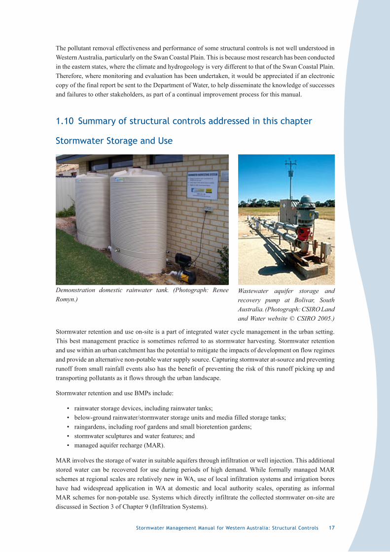
Stormwater retention and use on-site is a part of integrated water cycle management in the urban setting. This best management practice is sometimes referred to as stormwater harvesting. Stormwater retention and use within an urban catchment has the potential to mitigate the impacts of development on flow regimes and provide an alternative non-potable water supply source. Capturing stormwater at-source and preventing runoff from small rainfall events also has the benefit of preventing the risk of this runoff picking up and transporting pollutants as it flows through the urban landscape.
Stormwater retention and use BMPs include:
• rainwater storage devices, including rainwater tanks;• below-ground rainwater/stormwater storage units and media filled storage tanks;• raingardens, including roof gardens and small bioretention gardens;• stormwater sculptures and water features; and• managed aquifer recharge (MAR).
MAR involves the storage of water in suitable aquifers through infiltration or well injection. This additional stored water can be recovered for use during periods of high demand. While formally managed MAR schemes at regional scales are relatively new in WA, use of local infiltration systems and irrigation bores have had widespread application in WA at domestic and local authority scales, operating as informal MAR schemes for non-potable use. Systems which directly infiltrate the collected stormwater on-site are discussed in Section 3 of Chapter 9 (Infiltration Systems).
Demonstration domestic rainwater tank. (Photograph: Renee Romyn.)
Wastewater aquifer storage and recovery pump at Bolivar, South Australia. (Photograph: CSIRO Land and Water website © CSIRO 2005.)
18 Stormwater Management Manual for Western Australia: Structural Controls
This manual does not address the use of rainwater storage systems to supply a drinking water source, although it is recognised that in many rural areas of Western Australia, roof water is the main water supply for drinking and domestic use. For more information on using roof water for human consumption, refer to the Department of Health and the Water Corporation.
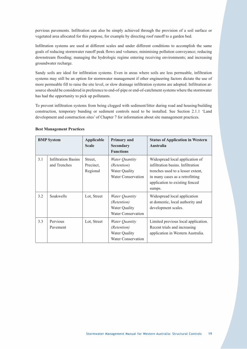
Best Management Practices
BMP System Applicable Scale
Primary and Secondary Functions
Status of Application in Western Australia
2.1 Rainwater Storage Systems
Lot, Street Water Conservation Water Quantity (Retention)
Traditionally applied in rural/regional areas. Increased recent application as a non-potable supply for urban development.
2.2 Managed Aquifer Recharge
Lot, Street, Precinct, Regional
Water Conservation Water Quantity (Retention)
Lot (domestic) and precinct schemes (local authority public open space irrigation) have widespread use. Use of MAR schemes at the regional scale is being trialled and researched. Some limited application in Perth metropolitan area.
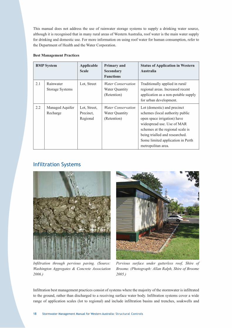
Infiltration Systems
Infiltration best management practices consist of systems where the majority of the stormwater is infiltrated to the ground, rather than discharged to a receiving surface water body. Infiltration systems cover a wide range of application scales (lot to regional) and include infiltration basins and trenches, soakwells and
Infiltration through pervious paving. (Source: Washington Aggregates & Concrete Association 2006.)
Pervious surface under gutterless roof, Shire of Broome. (Photograph: Allan Ralph, Shire of Broome 2005.)
Stormwater Management Manual for Western Australia: Structural Controls 19
pervious pavements. Infiltration can also be simply achieved through the provision of a soil surface or vegetated area allocated for this purpose, for example by directing roof runoff to a garden bed.
Infiltration systems are used at different scales and under different conditions to accomplish the same goals of reducing stormwater runoff peak flows and volumes; minimising pollution conveyance; reducing downstream flooding; managing the hydrologic regime entering receiving environments; and increasing groundwater recharge.
Sandy soils are ideal for infiltration systems. Even in areas where soils are less permeable, infiltration systems may still be an option for stormwater management if other engineering factors dictate the use of more permeable fill to raise the site level, or slow drainage infiltration systems are adopted. Infiltration at-source should be considered in preference to end-of-pipe or end-of-catchment systems where the stormwater has had the opportunity to pick up pollutants.
To prevent infiltration systems from being clogged with sediment/litter during road and housing/building construction, temporary bunding or sediment controls need to be installed. See Section 2.1.1 ‘Land development and construction sites’ of Chapter 7 for information about site management practices.
Best Management Practices
BMP System Applicable Scale
Primary and Secondary Functions
Status of Application in Western Australia
3.1 Infiltration Basins and Trenches
Street, Precinct, Regional
Water Quantity (Retention) Water Quality Water Conservation
Widespread local application of infiltration basins. Infiltration trenches used to a lesser extent, in many cases as a retrofitting application to existing fenced sumps.
3.2 Soakwells Lot, Street Water Quantity (Retention) Water Quality Water Conservation
Widespread local application at domestic, local authority and development scales.
3.3 Pervious Pavement
Lot, Street Water Quantity (Retention) Water Quality Water Conservation
Limited previous local application. Recent trials and increasing application in Western Australia.
20 Stormwater Management Manual for Western Australia: Structural Controls
Conveyance Systems
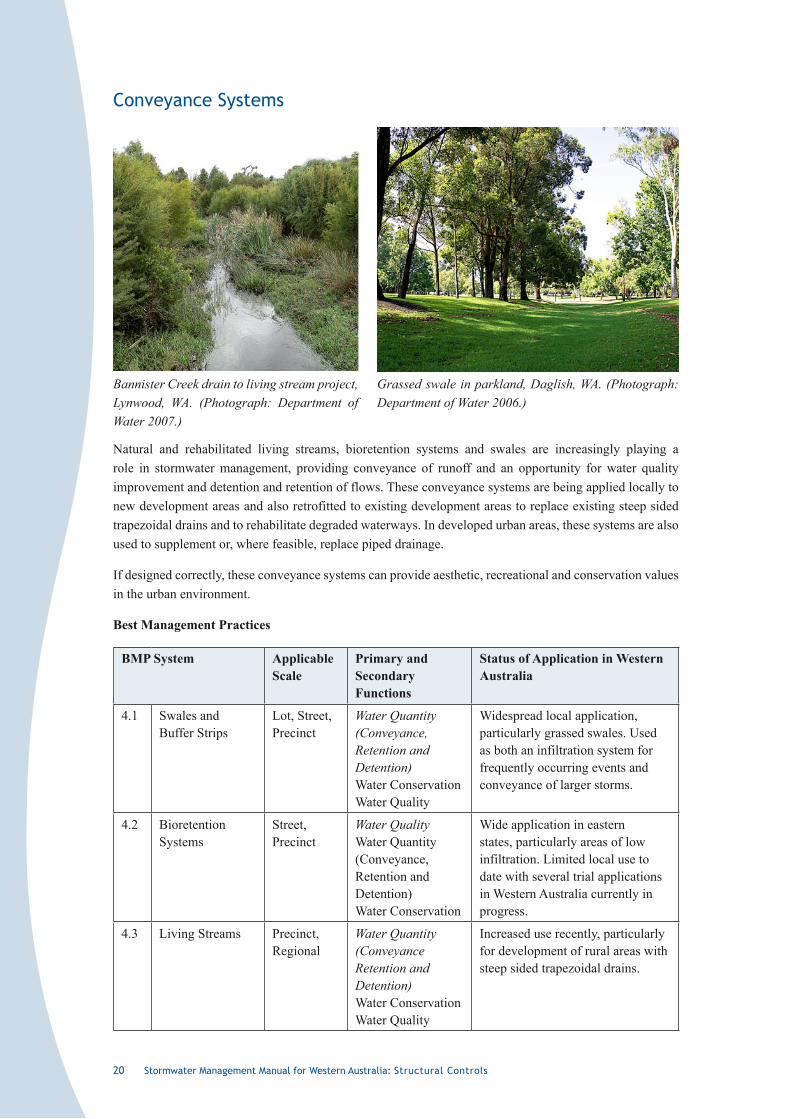
Natural and rehabilitated living streams, bioretention systems and swales are increasingly playing a role in stormwater management, providing conveyance of runoff and an opportunity for water quality improvement and detention and retention of flows. These conveyance systems are being applied locally to new development areas and also retrofitted to existing development areas to replace existing steep sided trapezoidal drains and to rehabilitate degraded waterways. In developed urban areas, these systems are also used to supplement or, where feasible, replace piped drainage.
If designed correctly, these conveyance systems can provide aesthetic, recreational and conservation values in the urban environment.
Best Management Practices
BMP System Applicable Scale
Primary and Secondary Functions
Status of Application in Western Australia
4.1 Swales and Buffer Strips
Lot, Street, Precinct
Water Quantity (Conveyance, Retention and Detention) Water Conservation Water Quality
Widespread local application, particularly grassed swales. Used as both an infiltration system for frequently occurring events and conveyance of larger storms.
4.2 Bioretention Systems
Street, Precinct
Water Quality Water Quantity (Conveyance, Retention and Detention) Water Conservation
Wide application in eastern states, particularly areas of low infiltration. Limited local use to date with several trial applications in Western Australia currently in progress.
4.3 Living Streams Precinct, Regional
Water Quantity (Conveyance Retention and Detention) Water Conservation Water Quality
Increased use recently, particularly for development of rural areas with steep sided trapezoidal drains.
Bannister Creek drain to living stream project, Lynwood, WA. (Photograph: Department of Water 2007.)
Grassed swale in parkland, Daglish, WA. (Photograph: Department of Water 2006.)
Stormwater Management Manual for Western Australia: Structural Controls 2�
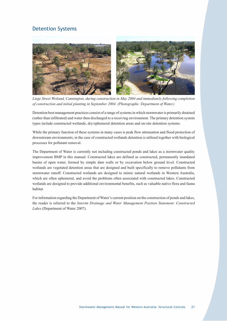
Detention Systems
Detention best management practices consist of a range of systems in which stormwater is primarily detained (rather than infiltrated) and water then discharged to a receiving environment. The primary detention system types include constructed wetlands, dry/ephemeral detention areas and on-site detention systems.
While the primary function of these systems in many cases is peak flow attenuation and flood protection of downstream environments, in the case of constructed wetlands detention is utilised together with biological processes for pollutant removal.
The Department of Water is currently not including constructed ponds and lakes as a stormwater quality improvement BMP in this manual. Constructed lakes are defined as constructed, permanently inundated basins of open water, formed by simple dam walls or by excavation below ground level. Constructed wetlands are vegetated detention areas that are designed and built specifically to remove pollutants from stormwater runoff. Constructed wetlands are designed to mimic natural wetlands in Western Australia, which are often ephemeral, and avoid the problems often associated with constructed lakes. Constructed wetlands are designed to provide additional environmental benefits, such as valuable native flora and fauna habitat.
For information regarding the Department of Water’s current position on the construction of ponds and lakes, the reader is referred to the Interim Drainage and Water Management Position Statement: Constructed Lakes (Department of Water 2007).
Liege Street Wetland, Cannington, during construction in May 2004 and immediately following completion of construction and initial planting in September 2004. (Photographs: Department of Water.)
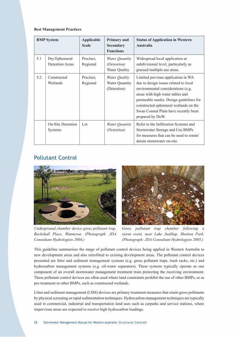
22 Stormwater Management Manual for Western Australia: Structural Controls
Best Management Practices
BMP System Applicable Scale
Primary and Secondary Functions
Status of Application in Western Australia
5.1 Dry/Ephemeral Detention Areas
Precinct, Regional
Water Quantity (Detention) Water Quality
Widespread local application at subdivisional level, particularly as grassed multiple use areas.
5.2 Constructed Wetlands
Precinct, Regional
Water Quality Water Quantity (Detention)
Limited previous application in WA due to design issues related to local environmental considerations (e.g. areas with high water tables and permeable sands). Design guidelines for constructed ephemeral wetlands on the Swan Coastal Plain have recently been prepared by DoW.
On-Site Detention Systems
Lot Water Quantity (Detention)
Refer to the Infiltration Systems and Stormwater Storage and Use BMPs for measures that can be used to retain/detain stormwater on-site.
Pollutant Control
This guideline summarises the range of pollutant control devices being applied in Western Australia to new development areas and also retrofitted to existing development areas. The pollutant control devices presented are litter and sediment management systems (e.g. gross pollutant traps, trash racks, etc.) and hydrocarbon management systems (e.g. oil-water separators). These systems typically operate as one component of an overall stormwater management treatment train protecting the receiving environment. These pollutant control devices are often used where land constraints prohibit the use of other BMPs, or as pre-treatment to other BMPs, such as constructed wetlands.
Litter and sediment management (LSM) devices are primary treatment measures that retain gross pollutants by physical screening or rapid sedimentation techniques. Hydrocarbon management techniques are typically used in commercial, industrial and transportation land uses such as carparks and service stations, where impervious areas are expected to receive high hydrocarbon loadings.
Underground chamber device gross pollutant trap, Backshall Place, Wanneroo. (Photograph: JDA Consultant Hydrologists 2004.)
Gross pollutant trap chamber following a storm event, near Lake Jualbup, Shenton Park. (Photograph: JDA Consultant Hydrologists 2005.)
Stormwater Management Manual for Western Australia: Structural Controls 23
Best Management Practices
BMP System Applicable Scale
Primary and Secondary Functions
Status of Application in Western Australia
6.1 Litter and Sediment Management
Lot, Street, Precinct
Water Quality Generally used as end-of-pipe solution to protect receiving environments, however should usually be applied at-source to target areas with potential for high pollutant runoff. At-source application is usually more cost effective than LSM systems applied in-transit or end-of-pipe. There is a range of LSM devices available in WA designed to target various types of pollutants. Used in new developments and retrofitted applications. Requirement for these devices for new developments has been reduced due to the focus on retention of stormwater at-source and disconnecting pollutant transport pathways.
6.2 Hydrocarbon Management
Lot, Street Water Quality Some installations along major roads and intersections in Western Australia to capture potential spills and treat road runoff. Increasingly used at-source in new developments and retrofitting applications to treat runoff from hardstand areas likely to contain hydrocarbon contamination, for example at service stations, carparks and industrial premises. Best used in combination with non-structural controls, such as good house-keeping practices on industrial sites, to minimise pollution of stormwater. Various hydrocarbon traps are available within Western Australia.
�.�� Case studies
Bridgewater South Estate, Mandurah
Project description
Bridgewater South Stage 3 subdivision is located between the Indian Ocean and the Peel-Harvey Estuary and is approximately 3.5 km south of Mandurah. The development was completed in 2005. The area has a Mediterranean-type climate, with hot, dry summers and cool, wet winters. The annual rainfall pattern for Mandurah is shown in Figure 1. The subdivision is located predominantly on relatively free draining light grey sands. Despite the generally high permeability soils, some areas have low infiltration capacity due to their proximity to the estuary, which leaves little separation between surface levels and groundwater levels at certain times of the year.
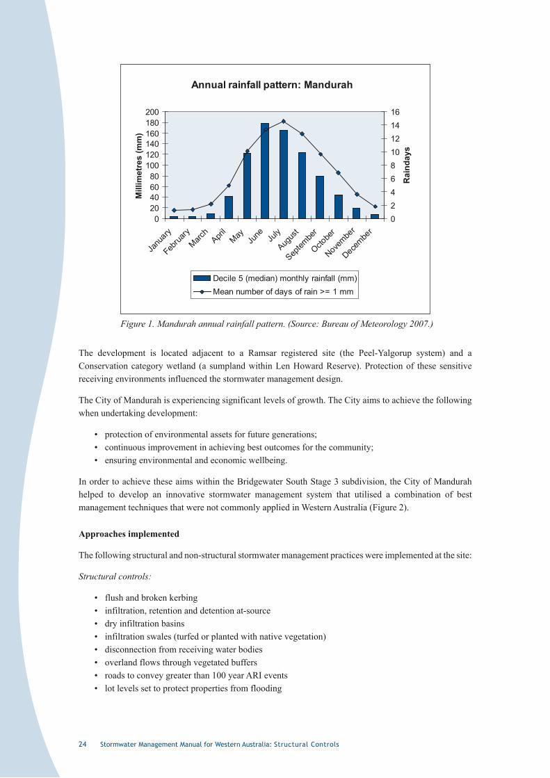
24 Stormwater Management Manual for Western Australia: Structural Controls
Annual rainfall pattern: Mandurah
020406080
100120140160180200
Janu
ary
Februa
ryMarc
hApri
lMay
June Ju
ly
Augus
t
Septem
ber
Octobe
r
Novembe
r
Decembe
r
Mill
imet
res
(mm
)
0246810121416
Rai
nday
s
Decile 5 (median) monthly rainfall (mm)Mean number of days of rain >= 1 mm
Figure 1. Mandurah annual rainfall pattern. (Source: Bureau of Meteorology 2007.)
The development is located adjacent to a Ramsar registered site (the Peel-Yalgorup system) and a Conservation category wetland (a sumpland within Len Howard Reserve). Protection of these sensitive receiving environments influenced the stormwater management design.
The City of Mandurah is experiencing significant levels of growth. The City aims to achieve the following when undertaking development:
• protection of environmental assets for future generations;• continuous improvement in achieving best outcomes for the community;• ensuring environmental and economic wellbeing.
In order to achieve these aims within the Bridgewater South Stage 3 subdivision, the City of Mandurah helped to develop an innovative stormwater management system that utilised a combination of best management techniques that were not commonly applied in Western Australia (Figure 2).
Approaches implemented
The following structural and non-structural stormwater management practices were implemented at the site:
Structural controls:
• flush and broken kerbing• infiltration, retention and detention at-source• dry infiltration basins• infiltration swales (turfed or planted with native vegetation)• disconnection from receiving water bodies• overland flows through vegetated buffers• roads to convey greater than 100 year ARI events• lot levels set to protect properties from flooding
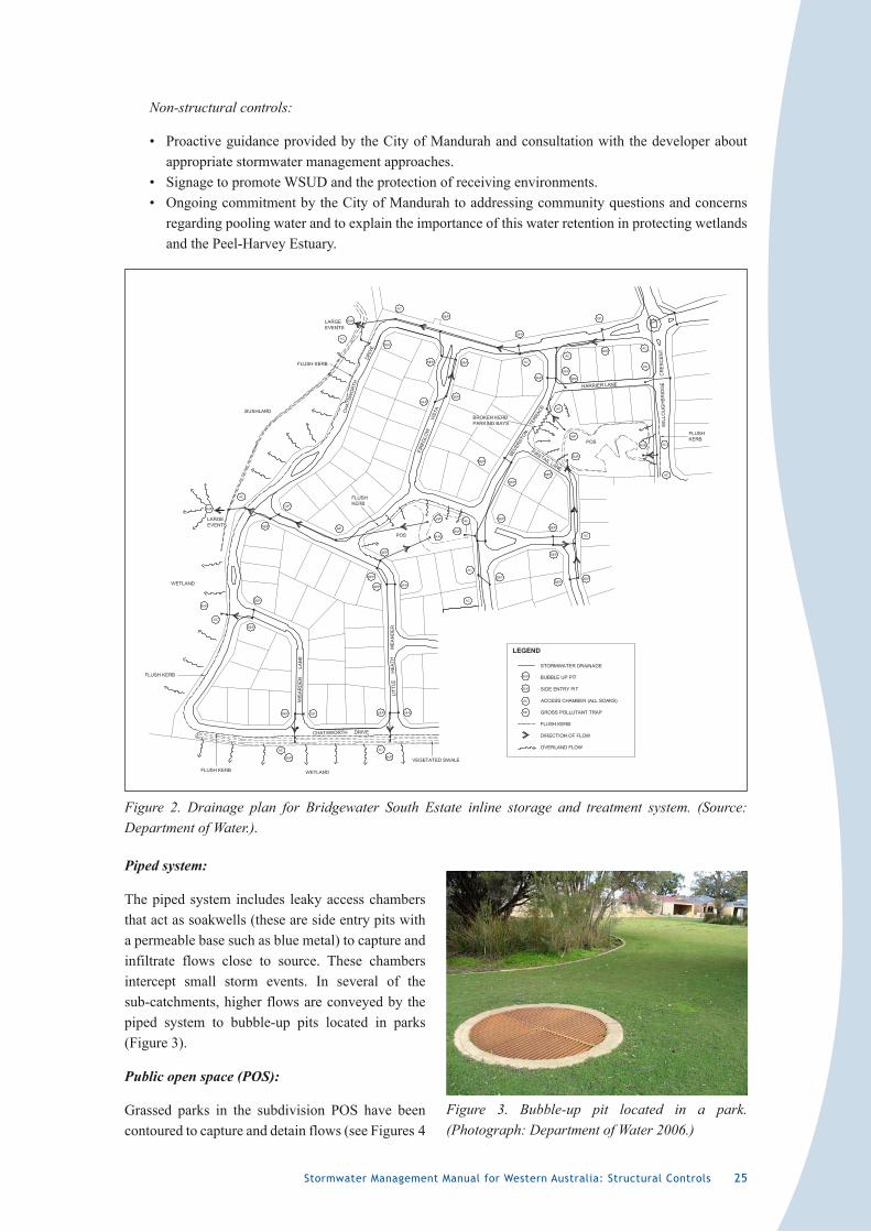
Stormwater Management Manual for Western Australia: Structural Controls 25
Non-structural controls:
• Proactive guidance provided by the City of Mandurah and consultation with the developer about appropriate stormwater management approaches.
• Signage to promote WSUD and the protection of receiving environments.• Ongoing commitment by the City of Mandurah to addressing community questions and concerns
regarding pooling water and to explain the importance of this water retention in protecting wetlands and the Peel-Harvey Estuary.
Figure 2. Drainage plan for Bridgewater South Estate inline storage and treatment system. (Source: Department of Water.).
Piped system:
The piped system includes leaky access chambers that act as soakwells (these are side entry pits with a permeable base such as blue metal) to capture and infiltrate flows close to source. These chambers intercept small storm events. In several of the sub-catchments, higher flows are conveyed by the piped system to bubble-up pits located in parks (Figure 3).
Public open space (POS):
Grassed parks in the subdivision POS have been contoured to capture and detain flows (see Figures 4
Figure 3. Bubble-up pit located in a park. (Photograph: Department of Water 2006.)
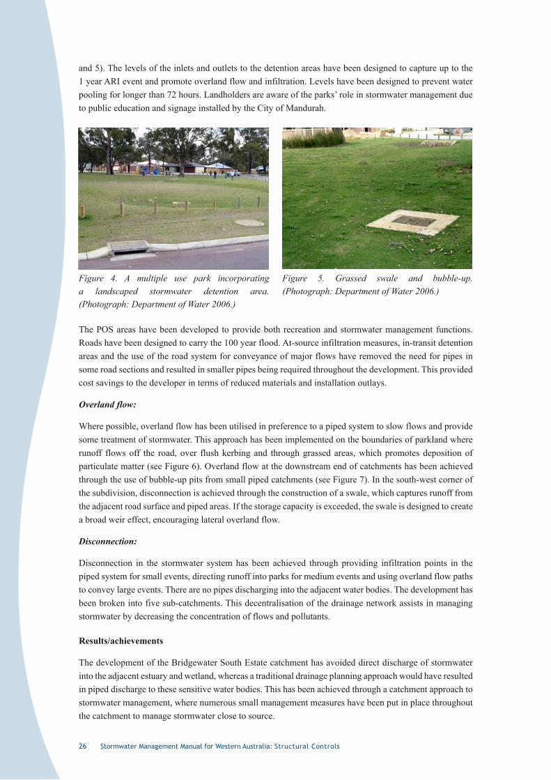
26 Stormwater Management Manual for Western Australia: Structural Controls
and 5). The levels of the inlets and outlets to the detention areas have been designed to capture up to the 1 year ARI event and promote overland flow and infiltration. Levels have been designed to prevent water pooling for longer than 72 hours. Landholders are aware of the parks’ role in stormwater management due to public education and signage installed by the City of Mandurah.
The POS areas have been developed to provide both recreation and stormwater management functions. Roads have been designed to carry the 100 year flood. At-source infiltration measures, in-transit detention areas and the use of the road system for conveyance of major flows have removed the need for pipes in some road sections and resulted in smaller pipes being required throughout the development. This provided cost savings to the developer in terms of reduced materials and installation outlays.
Overland flow:
Where possible, overland flow has been utilised in preference to a piped system to slow flows and provide some treatment of stormwater. This approach has been implemented on the boundaries of parkland where runoff flows off the road, over flush kerbing and through grassed areas, which promotes deposition of particulate matter (see Figure 6). Overland flow at the downstream end of catchments has been achieved through the use of bubble-up pits from small piped catchments (see Figure 7). In the south-west corner of the subdivision, disconnection is achieved through the construction of a swale, which captures runoff from the adjacent road surface and piped areas. If the storage capacity is exceeded, the swale is designed to create a broad weir effect, encouraging lateral overland flow.
Disconnection:
Disconnection in the stormwater system has been achieved through providing infiltration points in the piped system for small events, directing runoff into parks for medium events and using overland flow paths to convey large events. There are no pipes discharging into the adjacent water bodies. The development has been broken into five sub-catchments. This decentralisation of the drainage network assists in managing stormwater by decreasing the concentration of flows and pollutants.
Results/achievements
The development of the Bridgewater South Estate catchment has avoided direct discharge of stormwater into the adjacent estuary and wetland, whereas a traditional drainage planning approach would have resulted in piped discharge to these sensitive water bodies. This has been achieved through a catchment approach to stormwater management, where numerous small management measures have been put in place throughout the catchment to manage stormwater close to source.
Figure 5. Grassed swale and bubble-up. (Photograph: Department of Water 2006.)
Figure 4. A multiple use park incorporating a landscaped stormwater detention area. (Photograph: Department of Water 2006.)
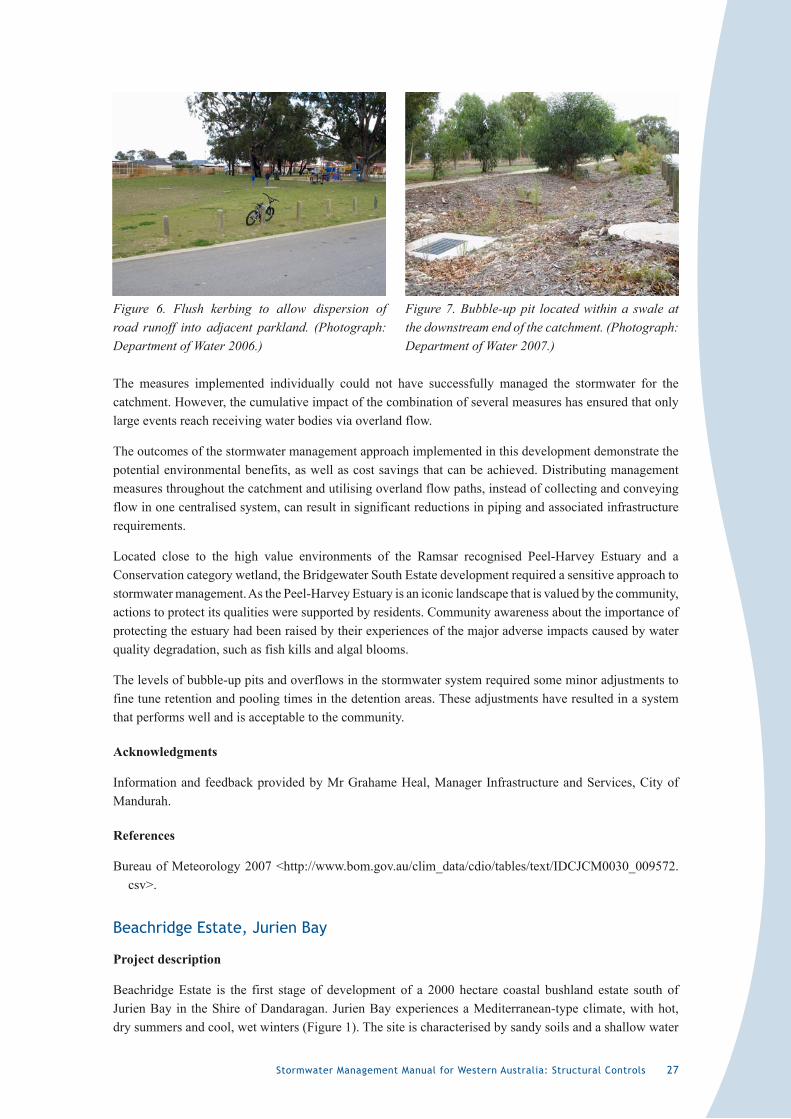
Stormwater Management Manual for Western Australia: Structural Controls 27
The measures implemented individually could not have successfully managed the stormwater for the catchment. However, the cumulative impact of the combination of several measures has ensured that only large events reach receiving water bodies via overland flow.
The outcomes of the stormwater management approach implemented in this development demonstrate the potential environmental benefits, as well as cost savings that can be achieved. Distributing management measures throughout the catchment and utilising overland flow paths, instead of collecting and conveying flow in one centralised system, can result in significant reductions in piping and associated infrastructure requirements.
Located close to the high value environments of the Ramsar recognised Peel-Harvey Estuary and a Conservation category wetland, the Bridgewater South Estate development required a sensitive approach to stormwater management. As the Peel-Harvey Estuary is an iconic landscape that is valued by the community, actions to protect its qualities were supported by residents. Community awareness about the importance of protecting the estuary had been raised by their experiences of the major adverse impacts caused by water quality degradation, such as fish kills and algal blooms.
The levels of bubble-up pits and overflows in the stormwater system required some minor adjustments to fine tune retention and pooling times in the detention areas. These adjustments have resulted in a system that performs well and is acceptable to the community.
Acknowledgments
Information and feedback provided by Mr Grahame Heal, Manager Infrastructure and Services, City of Mandurah.
References
Bureau of Meteorology 2007 <http://www.bom.gov.au/clim_data/cdio/tables/text/IDCJCM0030_009572.csv>.
Beachridge Estate, Jurien Bay
Project description
Beachridge Estate is the first stage of development of a 2000 hectare coastal bushland estate south of Jurien Bay in the Shire of Dandaragan. Jurien Bay experiences a Mediterranean-type climate, with hot, dry summers and cool, wet winters (Figure 1). The site is characterised by sandy soils and a shallow water
Figure 6. Flush kerbing to allow dispersion of road runoff into adjacent parkland. (Photograph: Department of Water 2006.)
Figure 7. Bubble-up pit located within a swale at the downstream end of the catchment. (Photograph: Department of Water 2007.)
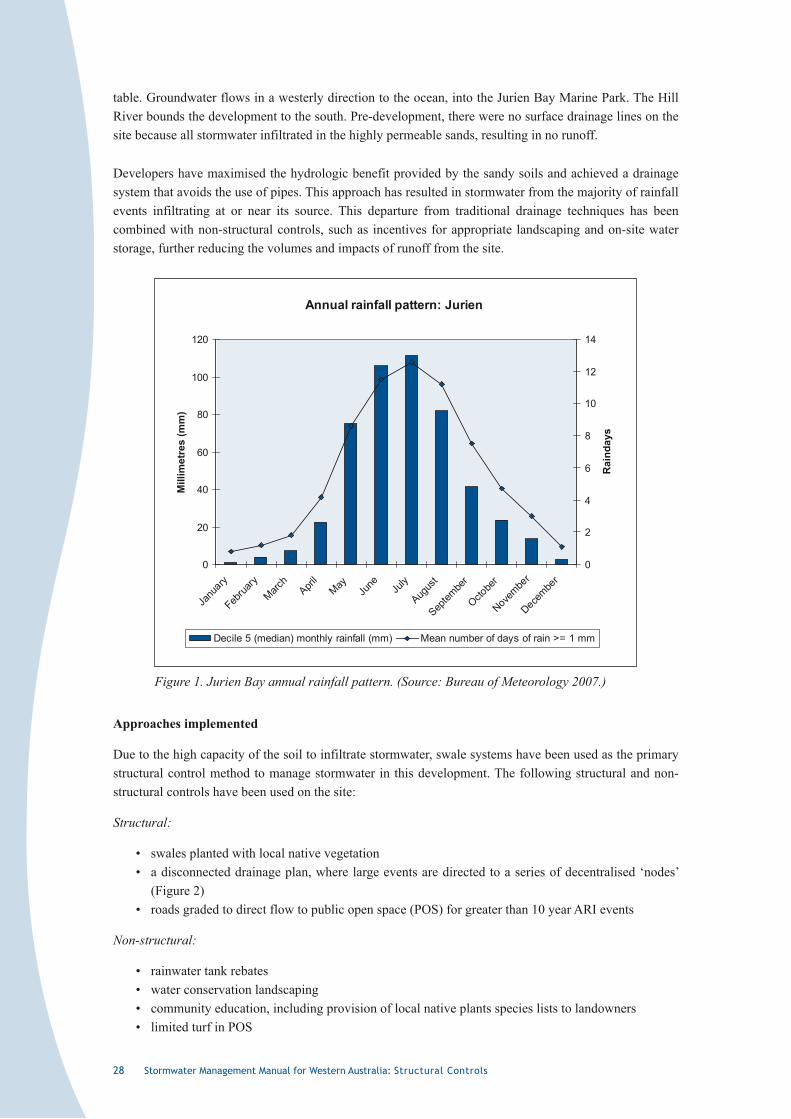
2� Stormwater Management Manual for Western Australia: Structural Controls
table. Groundwater flows in a westerly direction to the ocean, into the Jurien Bay Marine Park. The Hill River bounds the development to the south. Pre-development, there were no surface drainage lines on the site because all stormwater infiltrated in the highly permeable sands, resulting in no runoff.
Developers have maximised the hydrologic benefit provided by the sandy soils and achieved a drainage system that avoids the use of pipes. This approach has resulted in stormwater from the majority of rainfall events infiltrating at or near its source. This departure from traditional drainage techniques has been combined with non-structural controls, such as incentives for appropriate landscaping and on-site water storage, further reducing the volumes and impacts of runoff from the site.
Annual rainfall pattern: Jurien
0
20
40
60
80
100
120
Janu
ary
Februa
ryMarc
hApri
lMay
June Ju
ly
Augus
t
Septem
ber
Octobe
r
Novembe
r
Decembe
r
Mill
imet
res
(mm
)
0
2
4
6
8
10
12
14
Rai
nday
s
Decile 5 (median) monthly rainfall (mm) Mean number of days of rain >= 1 mm
Figure 1. Jurien Bay annual rainfall pattern. (Source: Bureau of Meteorology 2007.)
Approaches implemented
Due to the high capacity of the soil to infiltrate stormwater, swale systems have been used as the primary structural control method to manage stormwater in this development. The following structural and non-structural controls have been used on the site:
Structural:
• swales planted with local native vegetation• a disconnected drainage plan, where large events are directed to a series of decentralised ‘nodes’
(Figure 2)• roads graded to direct flow to public open space (POS) for greater than 10 year ARI events
Non-structural:
• rainwater tank rebates• water conservation landscaping• community education, including provision of local native plants species lists to landowners• limited turf in POS
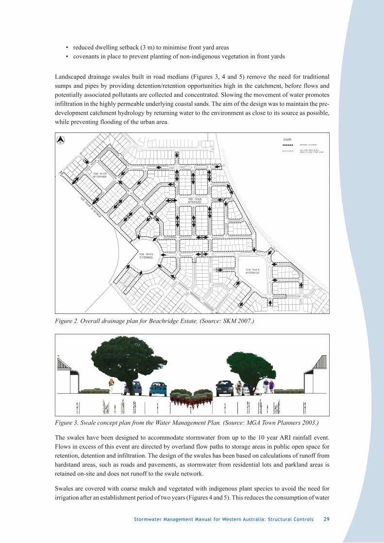
Stormwater Management Manual for Western Australia: Structural Controls 29
• reduced dwelling setback (3 m) to minimise front yard areas• covenants in place to prevent planting of non-indigenous vegetation in front yards
Landscaped drainage swales built in road medians (Figures 3, 4 and 5) remove the need for traditional sumps and pipes by providing detention/retention opportunities high in the catchment, before flows and potentially associated pollutants are collected and concentrated. Slowing the movement of water promotes infiltration in the highly permeable underlying coastal sands. The aim of the design was to maintain the pre-development catchment hydrology by returning water to the environment as close to its source as possible, while preventing flooding of the urban area.
Figure 2. Overall drainage plan for Beachridge Estate. (Source: SKM 2007.)
Figure 3. Swale concept plan from the Water Management Plan. (Source: MGA Town Planners 2003.)
The swales have been designed to accommodate stormwater from up to the 10 year ARI rainfall event. Flows in excess of this event are directed by overland flow paths to storage areas in public open space for retention, detention and infiltration. The design of the swales has been based on calculations of runoff from hardstand areas, such as roads and pavements, as stormwater from residential lots and parkland areas is retained on-site and does not runoff to the swale network.
Swales are covered with coarse mulch and vegetated with indigenous plant species to avoid the need for irrigation after an establishment period of two years (Figures 4 and 5). This reduces the consumption of water
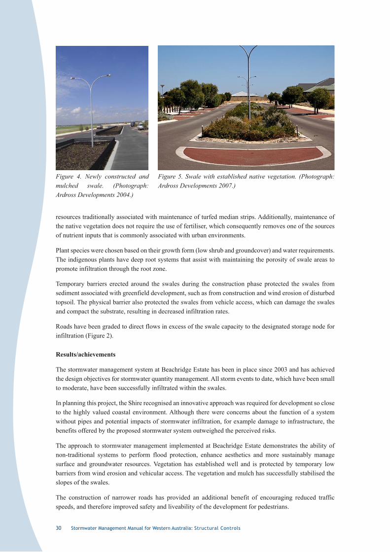
30 Stormwater Management Manual for Western Australia: Structural Controls
resources traditionally associated with maintenance of turfed median strips. Additionally, maintenance of the native vegetation does not require the use of fertiliser, which consequently removes one of the sources of nutrient inputs that is commonly associated with urban environments.
Plant species were chosen based on their growth form (low shrub and groundcover) and water requirements. The indigenous plants have deep root systems that assist with maintaining the porosity of swale areas to promote infiltration through the root zone.
Temporary barriers erected around the swales during the construction phase protected the swales from sediment associated with greenfield development, such as from construction and wind erosion of disturbed topsoil. The physical barrier also protected the swales from vehicle access, which can damage the swales and compact the substrate, resulting in decreased infiltration rates.
Roads have been graded to direct flows in excess of the swale capacity to the designated storage node for infiltration (Figure 2).
Results/achievements
The stormwater management system at Beachridge Estate has been in place since 2003 and has achieved the design objectives for stormwater quantity management. All storm events to date, which have been small to moderate, have been successfully infiltrated within the swales.
In planning this project, the Shire recognised an innovative approach was required for development so close to the highly valued coastal environment. Although there were concerns about the function of a system without pipes and potential impacts of stormwater infiltration, for example damage to infrastructure, the benefits offered by the proposed stormwater system outweighed the perceived risks.
The approach to stormwater management implemented at Beachridge Estate demonstrates the ability of non-traditional systems to perform flood protection, enhance aesthetics and more sustainably manage surface and groundwater resources. Vegetation has established well and is protected by temporary low barriers from wind erosion and vehicular access. The vegetation and mulch has successfully stabilised the slopes of the swales.
The construction of narrower roads has provided an additional benefit of encouraging reduced traffic speeds, and therefore improved safety and liveability of the development for pedestrians.
Figure 4. Newly constructed and mulched swale. (Photograph: Ardross Developments 2004.)
Figure 5. Swale with established native vegetation. (Photograph: Ardross Developments 2007.)
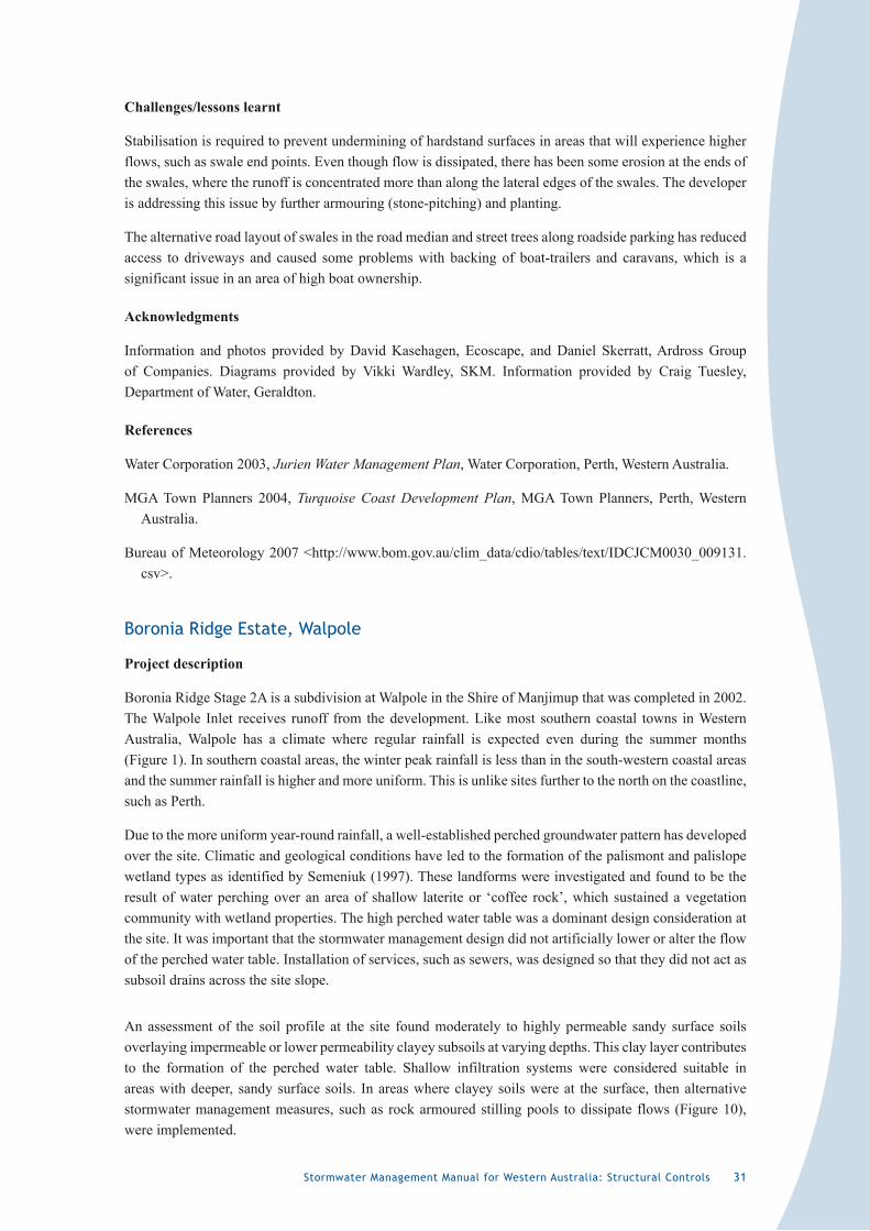
Stormwater Management Manual for Western Australia: Structural Controls 3�
Challenges/lessons learnt
Stabilisation is required to prevent undermining of hardstand surfaces in areas that will experience higher flows, such as swale end points. Even though flow is dissipated, there has been some erosion at the ends of the swales, where the runoff is concentrated more than along the lateral edges of the swales. The developer is addressing this issue by further armouring (stone-pitching) and planting.
The alternative road layout of swales in the road median and street trees along roadside parking has reduced access to driveways and caused some problems with backing of boat-trailers and caravans, which is a significant issue in an area of high boat ownership.
Acknowledgments
Information and photos provided by David Kasehagen, Ecoscape, and Daniel Skerratt, Ardross Group of Companies. Diagrams provided by Vikki Wardley, SKM. Information provided by Craig Tuesley, Department of Water, Geraldton.
References
Water Corporation 2003, Jurien Water Management Plan, Water Corporation, Perth, Western Australia.
MGA Town Planners 2004, Turquoise Coast Development Plan, MGA Town Planners, Perth, Western Australia.
Bureau of Meteorology 2007 <http://www.bom.gov.au/clim_data/cdio/tables/text/IDCJCM0030_009131.csv>.
Boronia Ridge Estate, Walpole
Project description
Boronia Ridge Stage 2A is a subdivision at Walpole in the Shire of Manjimup that was completed in 2002. The Walpole Inlet receives runoff from the development. Like most southern coastal towns in Western Australia, Walpole has a climate where regular rainfall is expected even during the summer months (Figure 1). In southern coastal areas, the winter peak rainfall is less than in the south-western coastal areas and the summer rainfall is higher and more uniform. This is unlike sites further to the north on the coastline, such as Perth.
Due to the more uniform year-round rainfall, a well-established perched groundwater pattern has developed over the site. Climatic and geological conditions have led to the formation of the palismont and palislope wetland types as identified by Semeniuk (1997). These landforms were investigated and found to be the result of water perching over an area of shallow laterite or ‘coffee rock’, which sustained a vegetation community with wetland properties. The high perched water table was a dominant design consideration at the site. It was important that the stormwater management design did not artificially lower or alter the flow of the perched water table. Installation of services, such as sewers, was designed so that they did not act as subsoil drains across the site slope.
An assessment of the soil profile at the site found moderately to highly permeable sandy surface soils overlaying impermeable or lower permeability clayey subsoils at varying depths. This clay layer contributes to the formation of the perched water table. Shallow infiltration systems were considered suitable in areas with deeper, sandy surface soils. In areas where clayey soils were at the surface, then alternative stormwater management measures, such as rock armoured stilling pools to dissipate flows (Figure 10), were implemented.
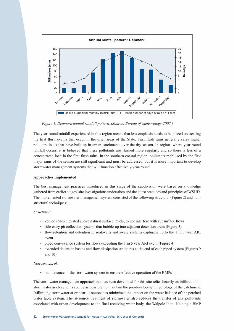
32 Stormwater Management Manual for Western Australia: Structural Controls
Annual rainfall pattern: Denmark
0
20
40
60
80
100
120
140
160
Janu
ary
Februa
ryMarc
hApri
lMay Ju
ne July
Augus
t
Septem
ber
Octobe
r
Novembe
r
Decembe
r
Mill
imet
res
(mm
)
0246810
1214161820
Rain
days
Decile 5 (median) monthly rainfall (mm) Mean number of days of rain >= 1 mm
Figure 1. Denmark annual rainfall pattern. (Source: Bureau of Meteorology 2007.)
The year-round rainfall experienced in this region means that less emphasis needs to be placed on treating the first flush events that occur in the drier areas of the State. First flush rains generally carry higher pollutant loads that have built up in urban catchments over the dry season. In regions where year-round rainfall occurs, it is believed that these pollutants are flushed more regularly and so there is less of a concentrated load in the first flush rains. In the southern coastal region, pollutants mobilised by the first major rains of the season are still significant and must be addressed, but it is more important to develop stormwater management systems that will function effectively year-round.
Approaches implemented
The best management practices introduced in this stage of the subdivision were based on knowledge gathered from earlier stages, site investigations undertaken and the latest practices and principles of WSUD. The implemented stormwater management system consisted of the following structural (Figure 2) and non-structural techniques:
Structural:
• kerbed roads elevated above natural surface levels, to not interfere with subsurface flows• side entry pit collection systems that bubble-up into adjacent detention areas (Figure 3)• flow retention and detention in soakwells and swale systems capturing up to the 1 in 1 year ARI
event• piped conveyance system for flows exceeding the 1 in 5 year ARI event (Figure 4)• extended detention basins and flow dissipation structures at the end of each piped system (Figures 9
and 10)
Non-structural:
• maintenance of the stormwater system to ensure effective operation of the BMPs
The stormwater management approach that has been developed for this site relies heavily on infiltration of stormwater as close to its source as possible, to maintain the pre-development hydrology of the catchment. Infiltrating stormwater at or near its source has minimised the impact on the water balance of the perched water table system. The at-source treatment of stormwater also reduces the transfer of any pollutants associated with urban development to the final receiving water body, the Walpole Inlet. No single BMP
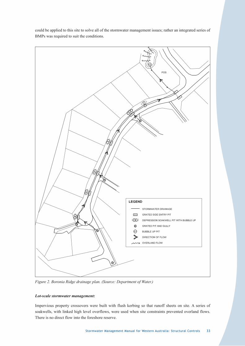
Stormwater Management Manual for Western Australia: Structural Controls 33
could be applied to this site to solve all of the stormwater management issues; rather an integrated series of BMPs was required to suit the conditions.
Figure 2. Boronia Ridge drainage plan. (Source: Department of Water.)
Lot-scale stormwater management:
Impervious property crossovers were built with flush kerbing so that runoff sheets on site. A series of soakwells, with linked high level overflows, were used when site constraints prevented overland flows. There is no direct flow into the foreshore reserve.
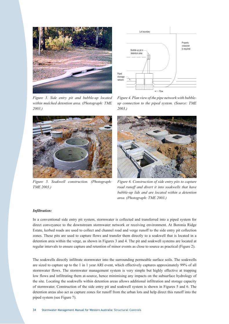
34 Stormwater Management Manual for Western Australia: Structural Controls
Infiltration:
In a conventional side entry pit system, stormwater is collected and transferred into a piped system for direct conveyance to the downstream stormwater network or receiving environment. At Boronia Ridge Estate, kerbed roads are used to collect and channel road and verge runoff to the side entry pit collection zones. These pits are used to capture flows and transfer them directly to a soakwell that is located in a detention area within the verge, as shown in Figures 3 and 4. The pit and soakwell systems are located at regular intervals to ensure capture and retention of minor events as close to source as practical (Figure 2).
The soakwells directly infiltrate stormwater into the surrounding permeable surface soils. The soakwells are sized to capture up to the 1 in 1 year ARI event, which effectively captures approximately 99% of all stormwater flows. The stormwater management system is very simple but highly effective at trapping low flows and infiltrating them at-source, hence minimising any impacts on the subsurface hydrology of the site. Locating the soakwells within detention areas allows additional infiltration and storage capacity of stormwater. Construction of the side entry pit and soakwell system is shown in Figures 5 and 6. The detention areas also act as capture zones for runoff from the urban lots and help direct this runoff into the piped system (see Figure 7).
Figure 4. Plan view of the pipe network with bubble-up connection to the piped system. (Source: TME 2003.)
Figure 3. Side entry pit and bubble-up located within mulched detention area. (Photograph: TME 2003.)
Figure 5. Soakwell construction. (Photograph: TME 2003.)
Figure 6. Construction of side entry pits to capture road runoff and divert it into soakwells that have bubble-up lids and are located within a detention area. (Photograph: TME 2003.)
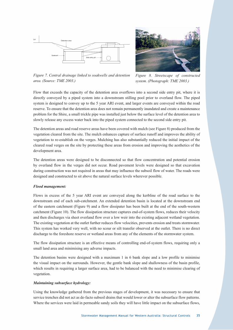
Stormwater Management Manual for Western Australia: Structural Controls 35
Flow that exceeds the capacity of the detention area overflows into a second side entry pit, where it is directly conveyed by a piped system into a downstream stilling pool prior to overland flow. The piped system is designed to convey up to the 5 year ARI event, and larger events are conveyed within the road reserve. To ensure that the detention area does not remain permanently inundated and create a maintenance problem for the Shire, a small trickle pipe was installed just below the surface level of the detention area to slowly release any excess water back into the piped system connected to the second side entry pit.
The detention areas and road reserve areas have been covered with mulch (see Figure 8) produced from the vegetation cleared from the site. The mulch enhances capture of surface runoff and improves the ability of vegetation to re-establish on the verges. Mulching has also substantially reduced the initial impact of the cleared road verges on the site by protecting these areas from erosion and improving the aesthetics of the development area.
The detention areas were designed to be disconnected so that flow concentration and potential erosion by overland flow in the verges did not occur. Road pavement levels were designed so that excavation during construction was not required in areas that may influence the subsoil flow of water. The roads were designed and constructed to sit above the natural surface levels wherever possible.
Flood management:
Flows in excess of the 5 year ARI event are conveyed along the kerbline of the road surface to the downstream end of each sub-catchment. An extended detention basin is located at the downstream end of the eastern catchment (Figure 9) and a flow dissipater has been built at the end of the south-western catchment (Figure 10). The flow dissipation structure captures end-of-system flows, reduces their velocity and then discharges via sheet overland flow over a low weir into the existing adjacent wetland vegetation. The existing vegetation at the outlet further reduces flow velocities, prevents erosion and treats stormwater. This system has worked very well, with no scour or silt transfer observed at the outlet. There is no direct discharge to the foreshore reserve or wetland areas from any of the elements of the stormwater system.
The flow dissipation structure is an effective means of controlling end-of-system flows, requiring only a small land area and minimising any adverse impacts.
The detention basins were designed with a maximum 1 in 6 bank slope and a low profile to minimise the visual impact on the surrounds. However, the gentle bank slope and shallowness of the basin profile, which results in requiring a larger surface area, had to be balanced with the need to minimise clearing of vegetation.
Maintaining subsurface hydrology:
Using the knowledge gathered from the previous stages of development, it was necessary to ensure that service trenches did not act as de-facto subsoil drains that would lower or alter the subsurface flow patterns. Where the services were laid in permeable sandy soils they will have little impact on the subsurface flows,
Figure 7. Central drainage linked to soakwells and detention area. (Source: TME 2003.)
Figure 8. Streetscape of constructed system. (Photograph: TME 2003.)
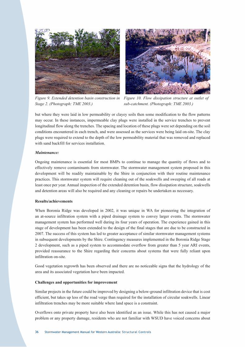
36 Stormwater Management Manual for Western Australia: Structural Controls
but where they were laid in low permeability or clayey soils then some modification to the flow patterns may occur. In these instances, impermeable clay plugs were installed in the service trenches to prevent longitudinal flow along the trenches. The spacing and location of these plugs were set depending on the soil conditions encountered in each trench, and were assessed as the services were being laid on-site. The clay plugs were required to extend to the depth of the low permeability material that was removed and replaced with sand backfill for services installation.
Maintenance:
Ongoing maintenance is essential for most BMPs to continue to manage the quantity of flows and to effectively remove contaminants from stormwater. The stormwater management system proposed in this development will be readily maintainable by the Shire in conjunction with their routine maintenance practices. This stormwater system will require cleaning out of the soakwells and sweeping of all roads at least once per year. Annual inspection of the extended detention basin, flow dissipation structure, soakwells and detention areas will also be required and any cleaning or repairs be undertaken as necessary.
Results/achievements
When Boronia Ridge was developed in 2002, it was unique in WA for pioneering the integration of an at-source infiltration system with a piped drainage system to convey larger events. The stormwater management system has performed well during its four years of operation. The experience gained in this stage of development has been extended to the design of the final stages that are due to be constructed in 2007. The success of this system has led to greater acceptance of similar stormwater management systems in subsequent developments by the Shire. Contingency measures implemented in the Boronia Ridge Stage 2 development, such as a piped system to accommodate overflow from greater than 5 year ARI events, provided reassurance to the Shire regarding their concerns about systems that were fully reliant upon infiltration on-site.
Good vegetation regrowth has been observed and there are no noticeable signs that the hydrology of the area and its associated vegetation have been impacted.
Challenges and opportunities for improvement
Similar projects in the future could be improved by designing a below-ground infiltration device that is cost efficient, but takes up less of the road verge than required for the installation of circular soakwells. Linear infiltration trenches may be more suitable where land space is a constraint.
Overflows onto private property have also been identified as an issue. While this has not caused a major problem or any property damage, residents who are not familiar with WSUD have voiced concerns about
Figure 9. Extended detention basin construction in Stage 2. (Photograph: TME 2003.)
Figure 10. Flow dissipation structure at outlet of sub-catchment. (Photograph: TME 2003.)
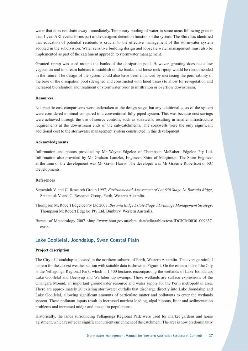
Stormwater Management Manual for Western Australia: Structural Controls 37
water that does not drain away immediately. Temporary pooling of water in some areas following greater than 1 year ARI events forms part of the designed detention function of the system. The Shire has identified that education of potential residents is crucial to the effective management of the stormwater system adopted in the subdivision. Water sensitive building design and lot-scale water management must also be implemented as part of the catchment approach to stormwater management.
Grouted riprap was used around the banks of the dissipation pool. However, grouting does not allow vegetation and in-stream habitats to establish on the banks, and loose rock riprap would be recommended in the future. The design of the system could also have been enhanced by increasing the permeability of the base of the dissipation pool (designed and constructed with lined bases) to allow for revegetation and increased bioretention and treatment of stormwater prior to infiltration or overflow downstream.
Resources
No specific cost comparisons were undertaken at the design stage, but any additional costs of the system were considered minimal compared to a conventional fully piped system. This was because cost savings were achieved through the use of source controls, such as soakwells, resulting in smaller infrastructure requirements at the downstream ends of the sub-catchments. The soakwells were the only significant additional cost to the stormwater management system constructed in this development.
Acknowledgments
Information and photos provided by Mr Wayne Edgeloe of Thompson McRobert Edgeloe Pty Ltd. Information also provided by Mr Graham Lantzke, Engineer, Shire of Manjimup. The Shire Engineer at the time of the development was Mr Gavin Harris. The developer was Mr Graeme Robertson of RC Developments.
References
Semeniuk V. and C. Research Group 1997, Environmental Assessment of Lot 650 Stage 2a Boronia Ridge, Semeniuk V. and C. Research Group, Perth, Western Australia.
Thompson McRobert Edgeloe Pty Ltd 2003, Boronia Ridge Estate Stage 3 Drainage Management Strategy, Thompson McRobert Edgeloe Pty Ltd, Bunbury, Western Australia.
Bureau of Meteorology 2007 <http://www.bom.gov.au/clim_data/cdio/tables/text/IDCJCM0030_009637.csv>.
Lake Goollelal, Joondalup, Swan Coastal Plain
Project description
The City of Joondalup is located in the northern suburbs of Perth, Western Australia. The average rainfall pattern for the closest weather station with suitable data is shown in Figure 1. On the eastern side of the City is the Yellagonga Regional Park, which is 1,400 hectares encompassing the wetlands of Lake Joondalup, Lake Goollelal and Beenyup and Walluburnup swamps. These wetlands are surface expressions of the Gnangara Mound, an important groundwater resource and water supply for the Perth metropolitan area. There are approximately 20 existing stormwater outfalls that discharge directly into Lake Joondalup and Lake Goollelal, allowing significant amounts of particulate matter and pollutants to enter the wetlands system. These pollutant inputs result in increased nutrient loading, algal blooms, litter and sedimentation problems and increased midge and mosquito populations.
Historically, the lands surrounding Yellagonga Regional Park were used for market gardens and horse agistment, which resulted in significant nutrient enrichment of the catchment. The area is now predominantly
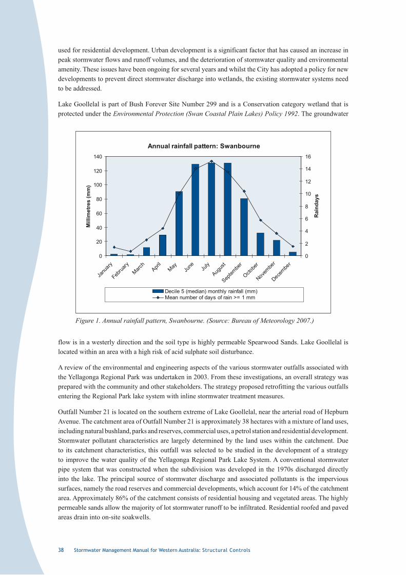
3� Stormwater Management Manual for Western Australia: Structural Controls
used for residential development. Urban development is a significant factor that has caused an increase in peak stormwater flows and runoff volumes, and the deterioration of stormwater quality and environmental amenity. These issues have been ongoing for several years and whilst the City has adopted a policy for new developments to prevent direct stormwater discharge into wetlands, the existing stormwater systems need to be addressed.
Lake Goollelal is part of Bush Forever Site Number 299 and is a Conservation category wetland that is protected under the Environmental Protection (Swan Coastal Plain Lakes) Policy 1992. The groundwater
Annual rainfall pattern: Swanbourne
0
20
40
60
80
100
120
140
Janu
ary
Februa
ryMarc
hApri
lMay
June Ju
ly
Augus
t
Septem
ber
Octobe
r
Novembe
r
Decembe
r
Mill
imet
res
(mm
)
0
2
4
6
8
10
12
14
16
Rai
nday
s
Decile 5 (median) monthly rainfall (mm)Mean number of days of rain >= 1 mm
Figure 1. Annual rainfall pattern, Swanbourne. (Source: Bureau of Meteorology 2007.)
flow is in a westerly direction and the soil type is highly permeable Spearwood Sands. Lake Goollelal is located within an area with a high risk of acid sulphate soil disturbance.
A review of the environmental and engineering aspects of the various stormwater outfalls associated with the Yellagonga Regional Park was undertaken in 2003. From these investigations, an overall strategy was prepared with the community and other stakeholders. The strategy proposed retrofitting the various outfalls entering the Regional Park lake system with inline stormwater treatment measures.
Outfall Number 21 is located on the southern extreme of Lake Goollelal, near the arterial road of Hepburn Avenue. The catchment area of Outfall Number 21 is approximately 38 hectares with a mixture of land uses, including natural bushland, parks and reserves, commercial uses, a petrol station and residential development. Stormwater pollutant characteristics are largely determined by the land uses within the catchment. Due to its catchment characteristics, this outfall was selected to be studied in the development of a strategy to improve the water quality of the Yellagonga Regional Park Lake System. A conventional stormwater pipe system that was constructed when the subdivision was developed in the 1970s discharged directly into the lake. The principal source of stormwater discharge and associated pollutants is the impervious surfaces, namely the road reserves and commercial developments, which account for 14% of the catchment area. Approximately 86% of the catchment consists of residential housing and vegetated areas. The highly permeable sands allow the majority of lot stormwater runoff to be infiltrated. Residential roofed and paved areas drain into on-site soakwells.
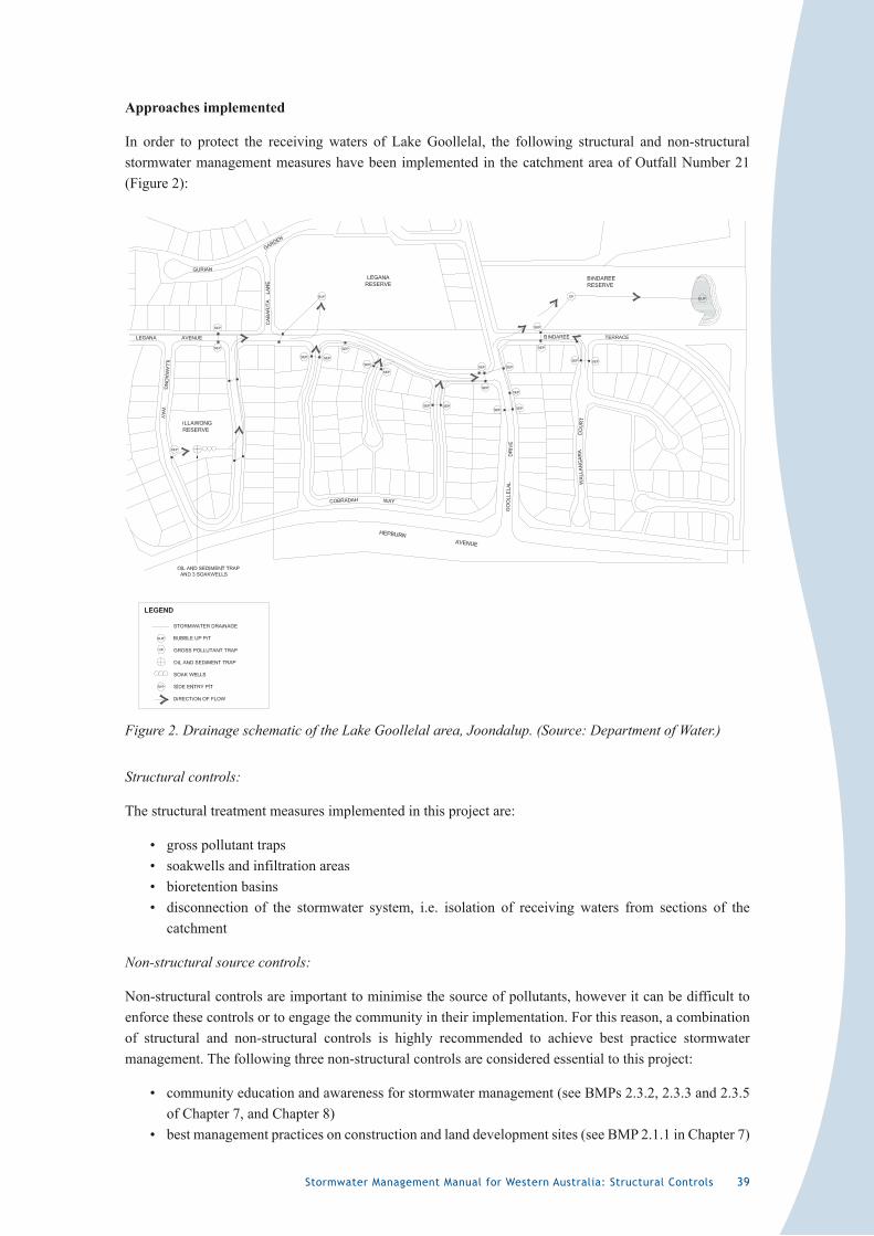
Stormwater Management Manual for Western Australia: Structural Controls 39
Approaches implemented
In order to protect the receiving waters of Lake Goollelal, the following structural and non-structural stormwater management measures have been implemented in the catchment area of Outfall Number 21 (Figure 2):
Figure 2. Drainage schematic of the Lake Goollelal area, Joondalup. (Source: Department of Water.)
Structural controls:
The structural treatment measures implemented in this project are:
• gross pollutant traps• soakwells and infiltration areas• bioretention basins• disconnection of the stormwater system, i.e. isolation of receiving waters from sections of the
catchment
Non-structural source controls:
Non-structural controls are important to minimise the source of pollutants, however it can be difficult to enforce these controls or to engage the community in their implementation. For this reason, a combination of structural and non-structural controls is highly recommended to achieve best practice stormwater management. The following three non-structural controls are considered essential to this project:
• community education and awareness for stormwater management (see BMPs 2.3.2, 2.3.3 and 2.3.5 of Chapter 7, and Chapter 8)
• best management practices on construction and land development sites (see BMP 2.1.1 in Chapter 7)
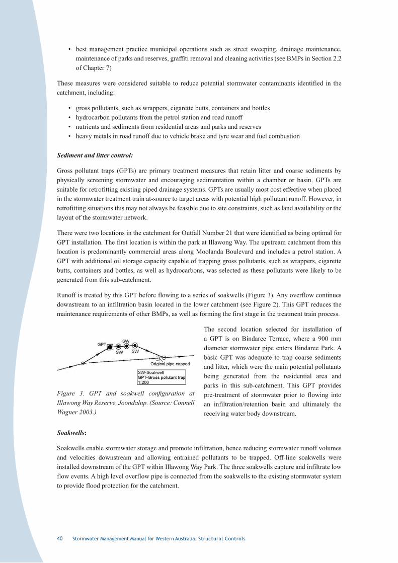
40 Stormwater Management Manual for Western Australia: Structural Controls
• best management practice municipal operations such as street sweeping, drainage maintenance, maintenance of parks and reserves, graffiti removal and cleaning activities (see BMPs in Section 2.2 of Chapter 7)
These measures were considered suitable to reduce potential stormwater contaminants identified in the catchment, including:
• gross pollutants, such as wrappers, cigarette butts, containers and bottles• hydrocarbon pollutants from the petrol station and road runoff• nutrients and sediments from residential areas and parks and reserves• heavy metals in road runoff due to vehicle brake and tyre wear and fuel combustion
Sediment and litter control:
Gross pollutant traps (GPTs) are primary treatment measures that retain litter and coarse sediments by physically screening stormwater and encouraging sedimentation within a chamber or basin. GPTs are suitable for retrofitting existing piped drainage systems. GPTs are usually most cost effective when placed in the stormwater treatment train at-source to target areas with potential high pollutant runoff. However, in retrofitting situations this may not always be feasible due to site constraints, such as land availability or the layout of the stormwater network.
There were two locations in the catchment for Outfall Number 21 that were identified as being optimal for GPT installation. The first location is within the park at Illawong Way. The upstream catchment from this location is predominantly commercial areas along Moolanda Boulevard and includes a petrol station. A GPT with additional oil storage capacity capable of trapping gross pollutants, such as wrappers, cigarette butts, containers and bottles, as well as hydrocarbons, was selected as these pollutants were likely to be generated from this sub-catchment.
Runoff is treated by this GPT before flowing to a series of soakwells (Figure 3). Any overflow continues downstream to an infiltration basin located in the lower catchment (see Figure 2). This GPT reduces the maintenance requirements of other BMPs, as well as forming the first stage in the treatment train process.
The second location selected for installation of a GPT is on Bindaree Terrace, where a 900 mm diameter stormwater pipe enters Bindaree Park. A basic GPT was adequate to trap coarse sediments and litter, which were the main potential pollutants being generated from the residential area and parks in this sub-catchment. This GPT provides pre-treatment of stormwater prior to flowing into an infiltration/retention basin and ultimately the receiving water body downstream.
Soakwells:
Soakwells enable stormwater storage and promote infiltration, hence reducing stormwater runoff volumes and velocities downstream and allowing entrained pollutants to be trapped. Off-line soakwells were installed downstream of the GPT within Illawong Way Park. The three soakwells capture and infiltrate low flow events. A high level overflow pipe is connected from the soakwells to the existing stormwater system to provide flood protection for the catchment.
Figure 3. GPT and soakwell configuration at Illawong Way Reserve, Joondalup. (Source: Connell Wagner 2003.)
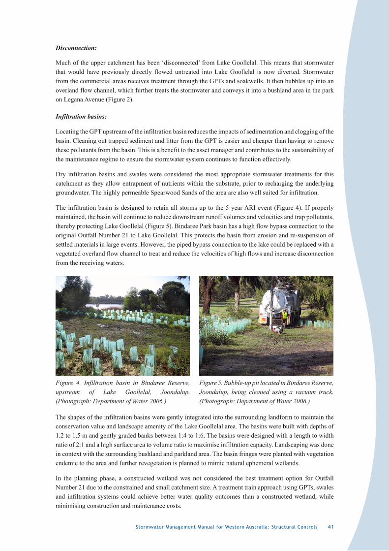
Stormwater Management Manual for Western Australia: Structural Controls 4�
Disconnection:
Much of the upper catchment has been ‘disconnected’ from Lake Goollelal. This means that stormwater that would have previously directly flowed untreated into Lake Goollelal is now diverted. Stormwater from the commercial areas receives treatment through the GPTs and soakwells. It then bubbles up into an overland flow channel, which further treats the stormwater and conveys it into a bushland area in the park on Legana Avenue (Figure 2).
Infiltration basins:
Locating the GPT upstream of the infiltration basin reduces the impacts of sedimentation and clogging of the basin. Cleaning out trapped sediment and litter from the GPT is easier and cheaper than having to remove these pollutants from the basin. This is a benefit to the asset manager and contributes to the sustainability of the maintenance regime to ensure the stormwater system continues to function effectively.
Dry infiltration basins and swales were considered the most appropriate stormwater treatments for this catchment as they allow entrapment of nutrients within the substrate, prior to recharging the underlying groundwater. The highly permeable Spearwood Sands of the area are also well suited for infiltration.
The infiltration basin is designed to retain all storms up to the 5 year ARI event (Figure 4). If properly maintained, the basin will continue to reduce downstream runoff volumes and velocities and trap pollutants, thereby protecting Lake Goollelal (Figure 5). Bindaree Park basin has a high flow bypass connection to the original Outfall Number 21 to Lake Goollelal. This protects the basin from erosion and re-suspension of settled materials in large events. However, the piped bypass connection to the lake could be replaced with a vegetated overland flow channel to treat and reduce the velocities of high flows and increase disconnection from the receiving waters.
The shapes of the infiltration basins were gently integrated into the surrounding landform to maintain the conservation value and landscape amenity of the Lake Goollelal area. The basins were built with depths of 1.2 to 1.5 m and gently graded banks between 1:4 to 1:6. The basins were designed with a length to width ratio of 2:1 and a high surface area to volume ratio to maximise infiltration capacity. Landscaping was done in context with the surrounding bushland and parkland area. The basin fringes were planted with vegetation endemic to the area and further revegetation is planned to mimic natural ephemeral wetlands.
In the planning phase, a constructed wetland was not considered the best treatment option for Outfall Number 21 due to the constrained and small catchment size. A treatment train approach using GPTs, swales and infiltration systems could achieve better water quality outcomes than a constructed wetland, while minimising construction and maintenance costs.
Figure 4. Infiltration basin in Bindaree Reserve, upstream of Lake Goollelal, Joondalup. (Photograph: Department of Water 2006.)
Figure 5. Bubble-up pit located in Bindaree Reserve, Joondalup, being cleaned using a vacuum truck. (Photograph: Department of Water 2006.)
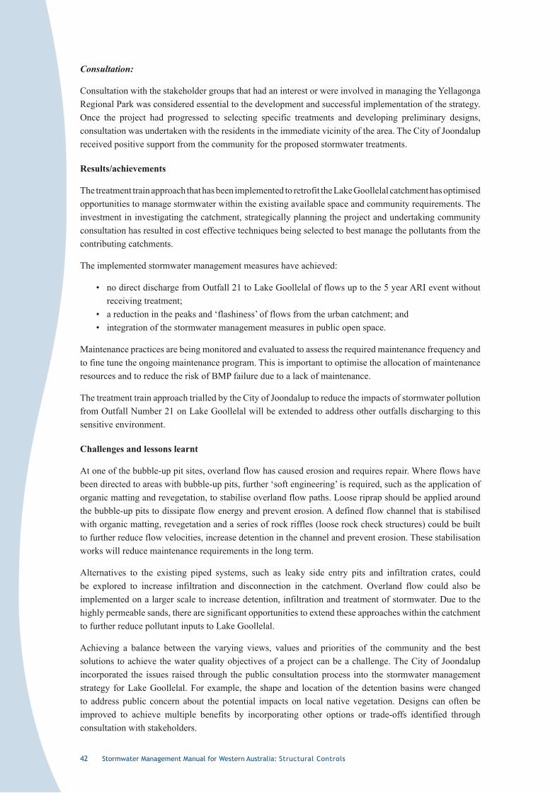
42 Stormwater Management Manual for Western Australia: Structural Controls
Consultation:
Consultation with the stakeholder groups that had an interest or were involved in managing the Yellagonga Regional Park was considered essential to the development and successful implementation of the strategy. Once the project had progressed to selecting specific treatments and developing preliminary designs, consultation was undertaken with the residents in the immediate vicinity of the area. The City of Joondalup received positive support from the community for the proposed stormwater treatments.
Results/achievements
The treatment train approach that has been implemented to retrofit the Lake Goollelal catchment has optimised opportunities to manage stormwater within the existing available space and community requirements. The investment in investigating the catchment, strategically planning the project and undertaking community consultation has resulted in cost effective techniques being selected to best manage the pollutants from the contributing catchments.
The implemented stormwater management measures have achieved:
• no direct discharge from Outfall 21 to Lake Goollelal of flows up to the 5 year ARI event without receiving treatment;
• a reduction in the peaks and ‘flashiness’ of flows from the urban catchment; and • integration of the stormwater management measures in public open space.
Maintenance practices are being monitored and evaluated to assess the required maintenance frequency and to fine tune the ongoing maintenance program. This is important to optimise the allocation of maintenance resources and to reduce the risk of BMP failure due to a lack of maintenance.
The treatment train approach trialled by the City of Joondalup to reduce the impacts of stormwater pollution from Outfall Number 21 on Lake Goollelal will be extended to address other outfalls discharging to this sensitive environment.
Challenges and lessons learnt
At one of the bubble-up pit sites, overland flow has caused erosion and requires repair. Where flows have been directed to areas with bubble-up pits, further ‘soft engineering’ is required, such as the application of organic matting and revegetation, to stabilise overland flow paths. Loose riprap should be applied around the bubble-up pits to dissipate flow energy and prevent erosion. A defined flow channel that is stabilised with organic matting, revegetation and a series of rock riffles (loose rock check structures) could be built to further reduce flow velocities, increase detention in the channel and prevent erosion. These stabilisation works will reduce maintenance requirements in the long term.
Alternatives to the existing piped systems, such as leaky side entry pits and infiltration crates, could be explored to increase infiltration and disconnection in the catchment. Overland flow could also be implemented on a larger scale to increase detention, infiltration and treatment of stormwater. Due to the highly permeable sands, there are significant opportunities to extend these approaches within the catchment to further reduce pollutant inputs to Lake Goollelal.
Achieving a balance between the varying views, values and priorities of the community and the best solutions to achieve the water quality objectives of a project can be a challenge. The City of Joondalup incorporated the issues raised through the public consultation process into the stormwater management strategy for Lake Goollelal. For example, the shape and location of the detention basins were changed to address public concern about the potential impacts on local native vegetation. Designs can often be improved to achieve multiple benefits by incorporating other options or trade-offs identified through consultation with stakeholders.

Stormwater Management Manual for Western Australia: Structural Controls 43
The City of Joondalup has recognised that to implement the changes required to improve stormwater quality and the health of Lake Goollelal, collaboration between State and local government, as well as industry and community groups, is required. The development of an Integrated Catchment Management Plan incorporating stormwater improvement strategies is also an important tool in achieving best practice stormwater management.
Resources
The cost for implementation of the pilot treatment works for Outfall Number 21 was approximately $100 000. This included two GPTs, three soakwells, five bubble-up pits and an infiltration basin.
Acknowledgments
Kym Hockley, Principal, Connell Wagner, and Peter Pikor, Manager Infrastructure Management and Ranger Services (previously), City of Joondalup provided information and endorsed this case study. David Djulbic, Director, Infrastructure and Operations, City of Joondalup, also endorsed this case study. Dave Mather, Coordinator Subdivisions/Civil Projects, City of Joondalup, provided additional information on the project progress.
References
Environmental Protection Authority 1992, Environmental Protection (Swan Coastal Plain Lakes) Policy 1992, Environmental Protection Authority, Perth, Western Australia. Available via <www.epa.wa.gov.au> or by telephoning (08) 9222 7000.
Hokley, K. and Pikor, P. 2006, ‘A stormwater management strategy for wetlands – Lake Goollelal Case Study’, Proceedings of the 2006 Public Works Engineering State Conference 8-10 March 2006, Perth, Western Australia.
Bureau of Meteorology 2007 <http://www.bom.gov.au/clim_data/cdio/tables/text/IDCJCM0030_009151.csv>.

44 Stormwater Management Manual for Western Australia: Structural Controls
�.�2 Acronyms
ARI Average recurrence interval
ARQ Australian Runoff Quality
ASS Acid sulphate soils
ASR Aquifer storage and recovery
BMP Best management practice
DIA Department of Indigenous Affairs
DEC Department of Environment and Conservation
DoW Department of Water
DWMS Drainage and water management strategy
EPA Environmental Protection Authority
EWR Ecological water requirement
GPT Gross pollutant trap
LSM Litter and sediment management
MAR Managed aquifer recharge
POS Public open space
PRI Phosphorus retention index
SMP Stormwater management plan
TDS Total dissolved solids
TN Total nitrogen
TP Total phosphorus
TSS Total suspended solids
UWMP Urban water management plan
WIN Water Information Network
WSUD Water sensitive urban design

Stormwater Management Manual for Western Australia: Structural Controls 45
�.�3 References and further reading
Agricultural and Resource Management Council of Australia and New Zealand (ARMCANZ) and Australian and New Zealand Environment and Conservation Council (ANZECC) 2000, National Water Quality Management Strategy No. 10, Australian Guidelines for Urban Stormwater Management, ARMCANZ and ANZECC, Canberra, Australian Capital Territory.
Coffman, L. 1997, Low Impact Development Design: a new paradigm for stormwater management mimicking and restoring the natural hydrologic regime, Department of Environmental Resources, Prince George’s County Maryland, United States of America.
Department of Environment 2003, General Guidance on Managing Acid Sulfate Soils, Department of Environment, Perth, Western Australia. Available via <http://acidsulfatesoils.environment.wa.gov.au>. Note: this information will eventually be located on <www.dec.wa.gov.au>.
Department of Health 2006, Mosquito Management Manual, Department of Health, Perth, Western Australia. Available by contacting Mosquito-Borne Disease Control Branch of the Department of Health.
Department of Water 2007, Interim Drainage and Water Management Position Statement: Constructed Lakes, Department of Water, Perth, Western Australia.
Engineers Australia 2006, Australian Runoff Quality – a guide to water sensitive urban design, Wong, T. H. F. (Editor-in-Chief), Engineers Media, Crows Nest, New South Wales.
Midge Research Group of Western Australia 2006, Chironomid Midge and Mosquito Risk Assessment Guide for Constructed Water Bodies, Midge Research Group of Western Australia, Perth, Western Australia. Available via <http://www.cockburn.wa.gov.au/midges/index.html>, go to Projects.
Mosquito Control Association of Australia Inc. 2002, Australian Mosquito Control Manual.
New South Wales Environment Protection Authority 1998, Managing Urban Stormwater – source controls, Draft, New South Wales Environmental Protection Authority, Sydney. Available via <www.environment.nsw.gov.au/stormwater/usp/docs.htm>.
Taylor, A. C. 2003, An Introduction to Life Cycle Costing Involving Structural Stormwater Quality Management Measures, Cooperative Research Centre for Catchment Hydrology, Melbourne, Victoria. Available via <www.catchment.crc.org.au/archive/pubs/1000130.html>.
Taylor, A.C. 2005, Structural Stormwater Quality BMP Cost/Size Relationship Information from the Literature (Version 3), Cooperative Research Centre for Catchment Hydrology, Melbourne, Victoria.
Taylor, A. C. and Wong, T. H. F. 2002, Non-Structural Stormwater Quality Best Management Practices: an overview of their use, value, cost and evaluation, Technical Report No. 02/11, Cooperative Research Centre for Catchment Hydrology, Melbourne, Victoria. Available via <www.catchment.crc.org.au/pdfs/technical200211.pdf>.
United States Environmental Protection Agency 1999, Preliminary Data Summary of Urban Stormwater Best Management Practices, United States Environmental Protection Agency, Washington. Available via <www.epa.gov/waterscience/guide/stormwater>.
Walsh, C. J., Leonard, A. W., Ladson, A. R. and Fletcher, T. D. 2004, Urban Stormwater and the Ecology of Streams, Cooperative Research Centre for Freshwater Ecology and Cooperative Research Centre for Catchment Hydrology, Canberra, Australia Capital Territory. Available via <www.catchment.crc.org.au/archive/pubs/1000143.html>.
Western Australian Planning Commission 2003, Planning Bulletin Number 64, Acid Sulfate Soils, Western Australian Planning Commission, Perth. Available via <www.planning.wa.gov.au/publications/policies/bulletins/PB64/PB64text.pdf>.

46 Stormwater Management Manual for Western Australia: Structural Controls
THIS PAGE HAS BEEN LEFT BLANK INTENTIONALLY