Embed Size (px)
Citation preview
Proceedings 24th Czech Concrete Days (2017) ISBN 978-80-906759-0-2 Session A: Invited Papers
1
STRUCTURAL CONCRETE DESIGN IN THE 21ST CENTURY: ARE LIMIT ANALYSIS METHODS OBSOLETE?
Walter Kaufmann1
Corresponding Author Jaime Mata-
Falcón1
Abstract
Limit analysis methods, whose origins date back to the early days of reinforced concrete, are powerful tools for the design, dimensioning and detailing of concrete structures. They are transparent, allow to trace the flow of forces and give the engineer control over the design. However, they are typically used as hand calculations, making their application tedious and time-consuming since iterations are required and several load-cases need to be considered. In addition, they are not directly applicable for checking serviceability criteria. Therefore, design in engineering practice is ever more often based on linear elastic finite element calculations. In order to ensure that limit analysis methods such as stress fields and truss models will continue to be used for reinforced concrete dimensioning and detailing, these models must be brought up-to-date by implementing them in user-friendly computer programs without impairing their advantages of transparency and control over the design. Currently, the authors are involved in the development of such a program, which will hopefully contribute to the survival of stress field and truss modelling in structural concrete design. Keywords: Limit analysis, structural concrete, dimensioning, design, truss models, strut-and-tie models, stress fields, discontinuity regions, graphic statics
1 Introduction – Historical Context
Design methods based on equilibrium have played a key role in the development of analysis and design methods for concrete structures. Prominent examples of such approaches, which from a modern perspective are essentially limit analysis methods, are truss models and stress fields for beams and walls, Hillerborg’s strip method [8] and the equivalent frame method for the design of slabs. Apart from these equilibrium approaches that yield lower bound (i.e. safe) estimates of the ultimate load, making them perfectly suitable for structural design,
24th Czech Concrete Days (2017) Proceedings Session A: Invited Papers 978-80-906759-0-2
2
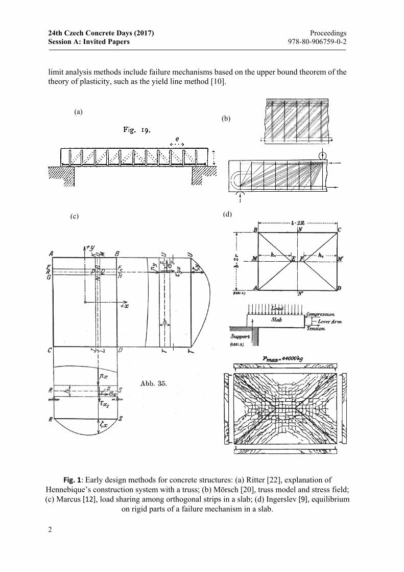
limit analysis methods include failure mechanisms based on the upper bound theorem of the theory of plasticity, such as the yield line method [10].
Fig. 1: Early design methods for concrete structures: (a) Ritter [22], explanation of
Hennebique’s construction system with a truss; (b) Mörsch [20], truss model and stress field; (c) Marcus [12], load sharing among orthogonal strips in a slab; (d) Ingerslev [9], equilibrium
on rigid parts of a failure mechanism in a slab.
(a) (b)
(c) (d)
Proceedings 24th Czech Concrete Days (2017) ISBN 978-80-906759-0-2 Session A: Invited Papers
3
The origins of limit analysis methods date back to the early days of reinforced concrete. For example, Ritter [22] and Mörsch [20] already sketched truss models, and even stress fields, to explain the load-bearing behaviour of reinforced concrete, Ingerslev [9] analysed failure mechanisms of slabs, and Marcus [12] designed slabs by sharing the load among orthogonal strips (Fig. 1). These methods, particularly truss models and stress fields, were however not established as scientific methods and, consequently, they were not widely used in the actual dimensioning of reinforced concrete structures. Rather, design codes were mainly based on comparing elastically determined stresses, e.g. principal tensile stresses in the webs of girders, to admissible values.
In the calculation of elastic stresses, it was usually implicitly assumed that the loading history was exactly known and structural systems were free from residual stresses and restraints. This is of course not correct, as pointed out by Melan [19] as early as 1938: “Da (…) die Reihenfolge der Belastungen willkürlich zu sein pflegt, hat die Frage nach einem Spannungszustand bei einer bestimmten Belastung keinen Sinn {Since (…) typically the sequence of loading is arbitrary, asking for the state of stress under a certain load does not make sense}”. This observation is particularly true for concrete structures, where the initial stresses, caused by restraint to imposed deformations (such as shrinkage strains), construction stages and other factors, are largely unknown indeed. In spite of this, admissible stress design kept being used until the second half of the 20th century. It was only through the advent of the theory of plasticity that truss models and stress fields, and limit analysis methods in general, were put on a solid theoretical basis, opening their way for being included in design codes.
2 Theorems of Limit Analysis
Limit analysis methods solve this intrinsic problem of admissible stress design: If sufficient ductility is ensured, the ultimate load is independent of residual stresses and restraints. Assuming perfectly plastic behaviour and postulating the principle of maximum dissipation energy (or, alternatively, applying the theory of plastic potential, i.e. convexity of the yield condition and orthogonality of the plastic strain increments to the yield surface), the following theorems can be derived [15]:
Lower bound theorem: Every loading for which it is possible to specify a statically admissible stress state that does not infringe the yield condition is not greater than the ultimate load.
Upper bound theorem: Every loading that results from equating the work of external forces for a kinematically admissible deformation state with the associated dissipation work is not less than the limit load.
The application of these theorems leads to the so-called static and kinematic methods of limit analysis, which define lower and upper bounds for the ultimate load allowing to bracket it. If upper and lower bound coincide, the actual ultimate limit load is found. In this case it is neither necessary to verify the existence of a statically admissible stress state for the governing deformation state, nor to identify a kinematically admissible deformation state for the governing stress state; this is known as compatibility theorem.
24th Czech Concrete Days (2017) Proceedings Session A: Invited Papers 978-80-906759-0-2
4
3 Application of Limit Analysis to Structural Concrete
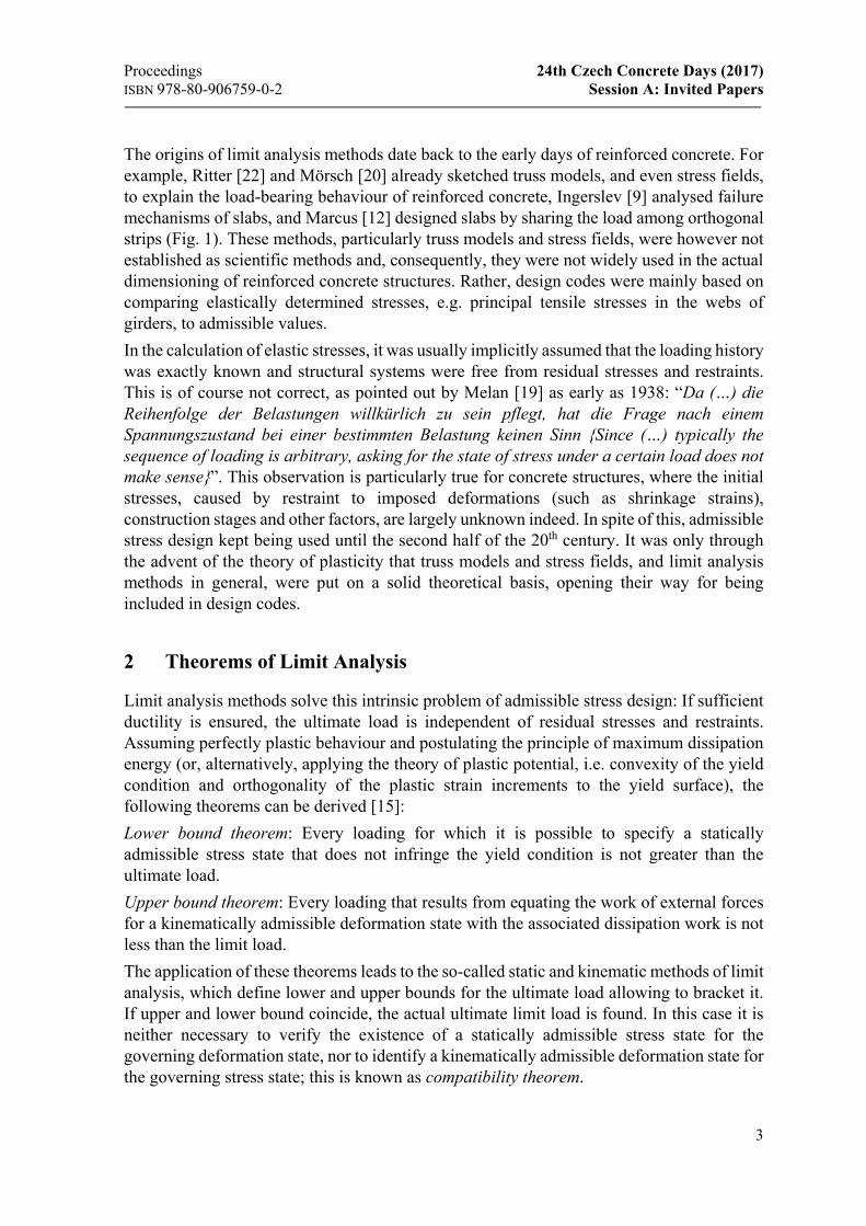
In the second half of the last century, pioneers like Nielsen [21] and Thürlimann and his co-workers [25], dared to apply the theory of plasticity to reinforced concrete. They were of course fully aware of the limited ductility of concrete and even reinforcement. Therefore, they completely neglected the tensile strength of concrete and addressed further concerns regarding ductility by providing minimum reinforcement (to avoid steel rupture at cracking) and using conservative limits for the so-called effective concrete compressive strength, as well as upper limits for the reinforcement quantities and corresponding compression zone depths (to avoid brittle failures due to concrete crushing).
(a)
(b) h
(c)
Fig. 2: Examples of modern lower-bound limit solutions of limit analysis (a) truss model and (b) corresponding, statically equivalent stress field; (c) Hillerborg’s strip method; (d)
yield conditions for slab and (e) membrane elements. Figures adapted from [16].
(d) (e)
Proceedings 24th Czech Concrete Days (2017) ISBN 978-80-906759-0-2 Session A: Invited Papers
5
Furthermore, they performed large-scale tests on structural elements to validate the results of limit analysis design, which was key to overcoming the initially fierce opposition that the pioneers of limit analysis were facing from many colleagues that were still advocating the use of the theory of elasticity. Later on, extensive investigations into the deformation capacity of structural concrete were carried out in order to determine the limits of applicability of limit analysis methods (e.g. [24], [1], [11], [17]). The results of these investigations are partly reflected in current design codes, e.g. through limits for moment redistribution in hyperstatic girders, bounds for the inclination of compression struts or compressive stress bands and, in particular, detailed rules for the determination of the effective concrete compressive strength.
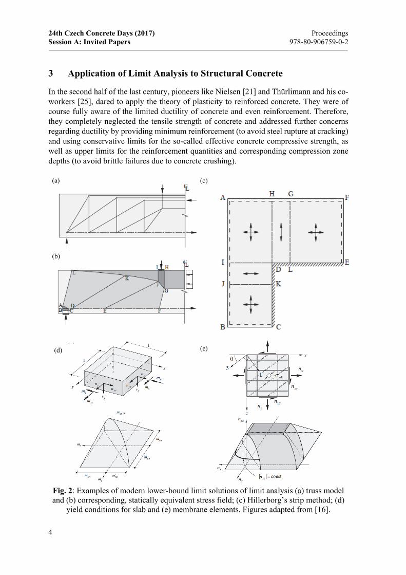
Lower-bound solutions (Fig. 2) provide a uniform basis for the safe design of concrete structures, and they often allow for a straightforward reinforcement design based on the applied loads, including the consistent dimensioning and detailing of the reinforcement with respect to the overall flow of forces. These aspects make them prone for the application in engineering practice, and consequently, many provisions in modern design codes are based on lower-bound solutions of limit analysis. While upper-bound approaches (Fig. 3) have not reached the same level of acceptance in engineering practice, they are powerful tools for the strength assessment of existing structures [16].
4 Awareness of Limit Analysis based Design Methods’ Background
The outline of the development of limit analysis methods and their influence on modern design codes presented above reflects the authors’ point of view. This perspective is shared by colleagues educated in countries that were at the forefront of the application of the theory
(a)
(b)
Fig. 3: Examples of modern upper-bound limit solutions of limit analysis: (a) Yield line
method; (b) failure mechanisms of beams and walls. Figures adapted from [16].
24th Czech Concrete Days (2017) Proceedings Session A: Invited Papers 978-80-906759-0-2
6
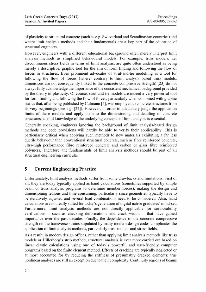
of plasticity to structural concrete (such as e.g. Switzerland and Scandinavian countries) and where limit analysis methods and their fundamentals are a key part of the education of structural engineers.
However, engineers with a different educational background often merely interpret limit analysis methods as simplified behavioural models. For example, truss models, i.e. discontinuous stress fields in terms of limit analysis, are quite often understood as being merely a descriptive, graphic tool for the aim of form finding and following the flow of forces in structures. Even prominent advocates of strut-and-tie modelling as a tool for following the flow of forces (where, contrary to limit analysis based truss models, dimensions are not consequently linked to the concrete compressive strength) [23] do not always fully acknowledge the importance of the consistent mechanical background provided by the theory of plasticity. Of course, strut-and-tie models are indeed a very powerful tool for form finding and following the flow of forces, particularly when combined with graphic statics that, after being published by Culmann [5], was employed to concrete structures from its very beginnings (see e.g. [22]). However, in order to adequately judge the application limits of these models and apply them to the dimensioning and detailing of concrete structures, a solid knowledge of the underlying concepts of limit analysis is essential.
Generally speaking, engineers ignoring the background of limit analysis-based design methods and code provisions will hardly be able to verify their applicability. This is particularly critical when applying such methods to new materials exhibiting a far less ductile behaviour than conventional structural concrete, such as fibre reinforced concrete, ultra-high performance fibre reinforced concrete and carbon or glass fibre reinforced polymers. Therefore, the fundamentals of limit analysis methods should be part of all structural engineering curricula.
5 Current Engineering Practice
Unfortunately, limit analysis methods suffer from some drawbacks and limitations. First of all, they are today typically applied as hand calculations (sometimes supported by simple beam or truss analysis programs to determine member forces), making the design and dimensioning tedious and time-consuming, particularly since geometries typically have to be iteratively adjusted and several load combinations need to be considered. Also, hand calculations are not really suited for today’s generation of digital native graduates’ mind-set. Furthermore, limit analysis methods are not directly applicable for serviceability verifications – such as checking deformations and crack widths – that have gained importance over the past decades. Finally, the dependence of the concrete compressive strength on the transverse strains stipulated by many modern design codes complicates the application of limit analysis methods, particularly truss models and stress fields.
As a result, in modern design offices, rather than applying limit analysis methods like truss models or Hillerborg’s strip method, structural analysis is ever more carried out based on linear elastic calculations using one of today’s powerful and user-friendly computer programs based on the finite element method. Effects of cracking are typically neglected or at most accounted for by reducing the stiffness of presumably cracked elements; true nonlinear analyses are still an exception due to their complexity. Continuity regions of beams
Proceedings 24th Czech Concrete Days (2017) ISBN 978-80-906759-0-2 Session A: Invited Papers
7
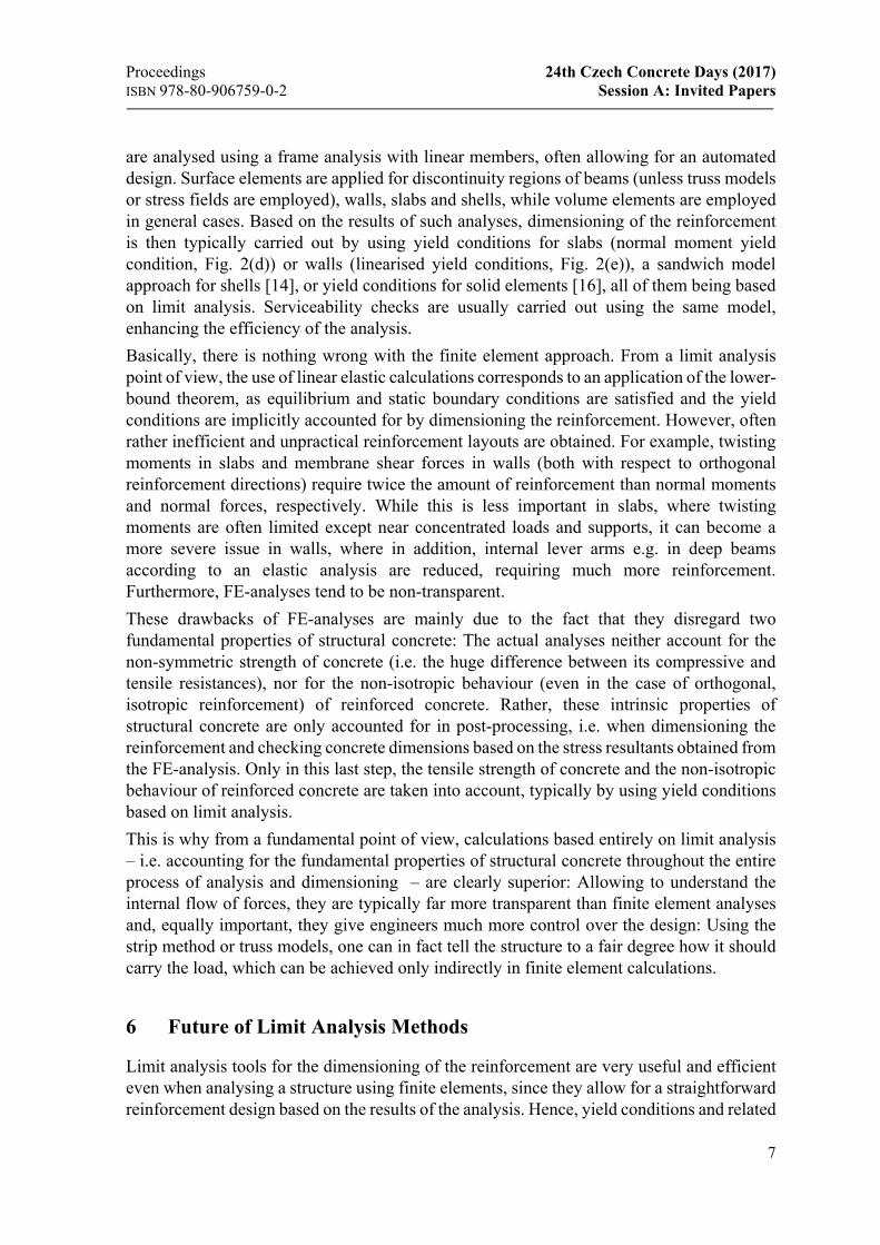
are analysed using a frame analysis with linear members, often allowing for an automated design. Surface elements are applied for discontinuity regions of beams (unless truss models or stress fields are employed), walls, slabs and shells, while volume elements are employed in general cases. Based on the results of such analyses, dimensioning of the reinforcement is then typically carried out by using yield conditions for slabs (normal moment yield condition, Fig. 2(d)) or walls (linearised yield conditions, Fig. 2(e)), a sandwich model approach for shells [14], or yield conditions for solid elements [16], all of them being based on limit analysis. Serviceability checks are usually carried out using the same model, enhancing the efficiency of the analysis.
Basically, there is nothing wrong with the finite element approach. From a limit analysis point of view, the use of linear elastic calculations corresponds to an application of the lower-bound theorem, as equilibrium and static boundary conditions are satisfied and the yield conditions are implicitly accounted for by dimensioning the reinforcement. However, often rather inefficient and unpractical reinforcement layouts are obtained. For example, twisting moments in slabs and membrane shear forces in walls (both with respect to orthogonal reinforcement directions) require twice the amount of reinforcement than normal moments and normal forces, respectively. While this is less important in slabs, where twisting moments are often limited except near concentrated loads and supports, it can become a more severe issue in walls, where in addition, internal lever arms e.g. in deep beams according to an elastic analysis are reduced, requiring much more reinforcement. Furthermore, FE-analyses tend to be non-transparent.
These drawbacks of FE-analyses are mainly due to the fact that they disregard two fundamental properties of structural concrete: The actual analyses neither account for the non-symmetric strength of concrete (i.e. the huge difference between its compressive and tensile resistances), nor for the non-isotropic behaviour (even in the case of orthogonal, isotropic reinforcement) of reinforced concrete. Rather, these intrinsic properties of structural concrete are only accounted for in post-processing, i.e. when dimensioning the reinforcement and checking concrete dimensions based on the stress resultants obtained from the FE-analysis. Only in this last step, the tensile strength of concrete and the non-isotropic behaviour of reinforced concrete are taken into account, typically by using yield conditions based on limit analysis.
This is why from a fundamental point of view, calculations based entirely on limit analysis – i.e. accounting for the fundamental properties of structural concrete throughout the entire process of analysis and dimensioning – are clearly superior: Allowing to understand the internal flow of forces, they are typically far more transparent than finite element analyses and, equally important, they give engineers much more control over the design: Using the strip method or truss models, one can in fact tell the structure to a fair degree how it should carry the load, which can be achieved only indirectly in finite element calculations.
6 Future of Limit Analysis Methods
Limit analysis tools for the dimensioning of the reinforcement are very useful and efficient even when analysing a structure using finite elements, since they allow for a straightforward reinforcement design based on the results of the analysis. Hence, yield conditions and related
24th Czech Concrete Days (2017) Proceedings Session A: Invited Papers 978-80-906759-0-2
8
models based on limit analysis, such as the sandwich model [14], have a good chance of being used by designers in the future.
This is not necessarily true for other limit analysis methods. The number of slabs designed using the strip method or yield line analysis is already low in most countries, and these methods are likely to diminish to an extent where they will mainly be used in education. Truss models and stress fields are more widely used today, and they have a good chance of being used in the future as a tool for form finding (graphic statics) and following the flow of forces in conceptual design. In the dimensioning and detailing of structural concrete, however, designers are more and more inclined to using finite element models for the reasons outlined above. If limit analysis methods remain being used essentially as hand calculations, and cannot be applied to serviceability checks, their use will be limited to education soon, just as in the case of slabs.
7 Truss Models and Stress Fields for the 21st Century
In order to facilitate the use of truss models and stress fields for the dimensioning and detailing of structural concrete in the future, their drawbacks must be overcome, yet without impairing their advantages of transparency and control over the design.
To this end, truss models and stress fields need to be implemented in a user-friendly software environment to make their application more efficient. Furthermore, by providing the elements with realistic stiffnesses, the models may be used for assessing the serviceability behaviour as well. This idea is far from being new: More than 30 years ago, Peter Marti [13] wrote: “There is a considerable potential for applying interactive computer programs with graphical input and output that could replace the traditional drawing board and pocket calculator methods for developing truss models. Apart from ultimate strength considerations, such programs would allow us to investigate the deformations in the cracked state by taking appropriate truss member stiffnesses into account.” Rather, it is astonishing that hardly any such programs are available today. One reason for this (as indicated by some sceptical comments of colleagues regarding our current work in this direction) may be that some advocates of graphic static and truss models as a tool for following the flow of forces consider hand sketches as a key element of truss modelling and have strong reservations against an implementation in computer programs. By doing so, however, they ignore the drawbacks of truss models as a hand calculation tool for (code-compliant) dimensioning and detailing in engineering practice and are ultimately of their own harm.
Several attempts to develop programs for automated truss modelling were made in the past decades, e.g. [26], [4]. Although some very interesting results were obtained, these programs did not find widespread application in engineering practice, presumably mainly due to a lack in user friendliness. While this could easily be improved by professional software developers, automated truss modelling is facing an intrinsic problem in the definition of the effective concrete compressive strength: While design codes specify values for specific situations (e.g. [2]), engineering judgment is required to assign the “correct” strength to the individual truss members and nodes. Since the truss geometry depends on the concrete strength and vice versa, this generally requires iterations involving user inputs which can be time-consuming, affecting user friendliness and efficiency.
Proceedings 24th Czech Concrete Days (2017) ISBN 978-80-906759-0-2 Session A: Invited Papers
9
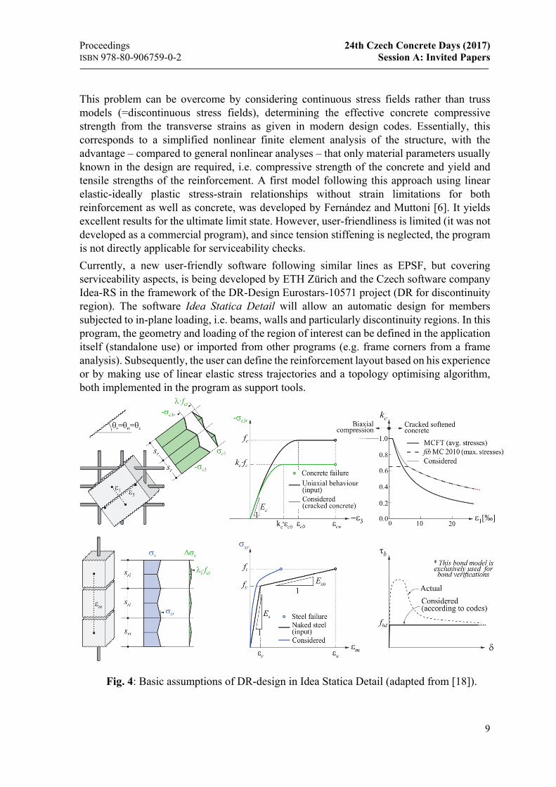
This problem can be overcome by considering continuous stress fields rather than truss models (=discontinuous stress fields), determining the effective concrete compressive strength from the transverse strains as given in modern design codes. Essentially, this corresponds to a simplified nonlinear finite element analysis of the structure, with the advantage – compared to general nonlinear analyses – that only material parameters usually known in the design are required, i.e. compressive strength of the concrete and yield and tensile strengths of the reinforcement. A first model following this approach using linear elastic-ideally plastic stress-strain relationships without strain limitations for both reinforcement as well as concrete, was developed by Fernández and Muttoni [6]. It yields excellent results for the ultimate limit state. However, user-friendliness is limited (it was not developed as a commercial program), and since tension stiffening is neglected, the program is not directly applicable for serviceability checks.
Currently, a new user-friendly software following similar lines as EPSF, but covering serviceability aspects, is being developed by ETH Zürich and the Czech software company Idea-RS in the framework of the DR-Design Eurostars-10571 project (DR for discontinuity region). The software Idea Statica Detail will allow an automatic design for members subjected to in-plane loading, i.e. beams, walls and particularly discontinuity regions. In this program, the geometry and loading of the region of interest can be defined in the application itself (standalone use) or imported from other programs (e.g. frame corners from a frame analysis). Subsequently, the user can define the reinforcement layout based on his experience or by making use of linear elastic stress trajectories and a topology optimising algorithm, both implemented in the program as support tools.
Fig. 4: Basic assumptions of DR-design in Idea Statica Detail (adapted from [18]).
24th Czech Concrete Days (2017) Proceedings Session A: Invited Papers 978-80-906759-0-2
10
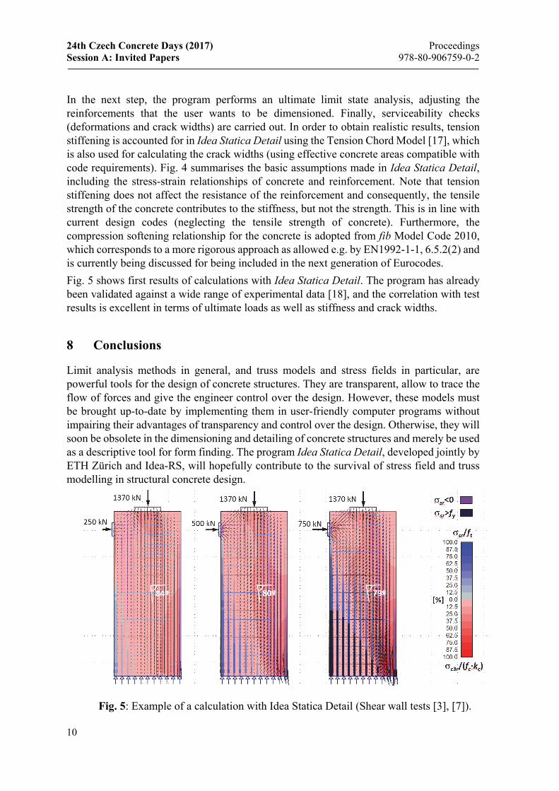
In the next step, the program performs an ultimate limit state analysis, adjusting the reinforcements that the user wants to be dimensioned. Finally, serviceability checks (deformations and crack widths) are carried out. In order to obtain realistic results, tension stiffening is accounted for in Idea Statica Detail using the Tension Chord Model [17], which is also used for calculating the crack widths (using effective concrete areas compatible with code requirements). Fig. 4 summarises the basic assumptions made in Idea Statica Detail, including the stress-strain relationships of concrete and reinforcement. Note that tension stiffening does not affect the resistance of the reinforcement and consequently, the tensile strength of the concrete contributes to the stiffness, but not the strength. This is in line with current design codes (neglecting the tensile strength of concrete). Furthermore, the compression softening relationship for the concrete is adopted from fib Model Code 2010, which corresponds to a more rigorous approach as allowed e.g. by EN1992-1-1, 6.5.2(2) and is currently being discussed for being included in the next generation of Eurocodes.
Fig. 5 shows first results of calculations with Idea Statica Detail. The program has already been validated against a wide range of experimental data [18], and the correlation with test results is excellent in terms of ultimate loads as well as stiffness and crack widths.
8 Conclusions
Limit analysis methods in general, and truss models and stress fields in particular, are powerful tools for the design of concrete structures. They are transparent, allow to trace the flow of forces and give the engineer control over the design. However, these models must be brought up-to-date by implementing them in user-friendly computer programs without impairing their advantages of transparency and control over the design. Otherwise, they will soon be obsolete in the dimensioning and detailing of concrete structures and merely be used as a descriptive tool for form finding. The program Idea Statica Detail, developed jointly by ETH Zürich and Idea-RS, will hopefully contribute to the survival of stress field and truss modelling in structural concrete design.
Fig. 5: Example of a calculation with Idea Statica Detail (Shear wall tests [3], [7]).
Proceedings 24th Czech Concrete Days (2017) ISBN 978-80-906759-0-2 Session A: Invited Papers
11
9 Acknowledgement and Final Remark
The development of Idea Statica Detail is part of the DR-Design Eurostars-10571 project and has received partial funding from the Eurostars-2 joint programme with co-funding from the European Union Horizon 2020 research and innovation programme. Their financial support is gratefully acknowledged. An abbreviated, modified version of the present contribution will be published in German as part of a collection of articles honouring Professor Joseph Schwartz of ETH Zürich on the occasion of his 60th birthday.
References
[1] Alvarez, M. (1998). «Einfluss des Verbundverhaltens auf das Verformungsvermögen von Stahlbeton». Institut für Baustatik und Konstruktion, ETH Zürich, IBK Bericht Nr. 236, Birkhäuser Verlag, Basel.
[2] American Concrete Institute. (2014). ACI 318 - Building Code Requirements for Structural Concrete and Commentary.
[3] Bimschas, M. (2010). «Displacement-Based Seismic Assessment of Existing Bridges in Regions of Moderate Seismicity”. IBK Report No. 326, Institute of Structural Engineering, ETH Zurich.
[4] Chae, H. (2016). Design Report (Eurocode2) - Deepbeam. HanGil IT. [5] Culmann, K. (1866). Die graphische Statik. Meyer und Zeller, Zürich. [6] Fernández Ruiz, M., & Muttoni, A. (2007). «On the development of suitable stress
fields for structural concrete”. ACI Structural Journal, 104(4), 495-502. [7] Hannewald, P., Bimschas, M., & Dazio, A. (2013). “Quasi-static cyclic tests on RC
bridge piers with detailing deficiencies”. IBK Report No. 352, Institute of Structural Engineering, ETH Zurich.
[8] Hillerborg, A. (1975). Strip Method of Design, Viewpoint, London. [9] Ingerslev, A. (1923). The Strength of Rectangular Slabs. Journal of the Institution of
Civil Engineers, 1, 3-14. [10] Johansen, K. W. (1962). Yield Line Theory. Cement and Concrete Association,
London. [11] Kaufmann, W. (1998). ”Strength and Deformations of Structural Concrete Subjected
to In-Plane Shear and Normal Forces”. IBK Report No. 234, Institute of Structural Engineering, ETH Zurich, Birkhäuser Verlag, Basel.
[12] Marcus, H. (1932). Die Theorie elastischer Gewebe und ihre Anwendung auf die Berechnung biegsamer Platten: Unter besonderer Berücksichtigung der trägerlosen Pilzdecken (Bd. 2). Julius Springer, Berlin.
[13] Marti, P. (1985). “Truss models in detailing”. Concrete International, 7(12), p. 66-73. [14] Marti, P. (1990). “Design of Concrete Slabs for transverse Shear”. ACI Structural
Journal, 87(2), p. 180-190. [15] Marti, P. (2011). Baustatik. Wilhelm Ernst & Sohn, Berlin. [16] Marti, P., Alvarez, M., Kaufmann, W., & Sigrist, V. (1999). "Tragverhalten von
Stahlbeton", Fortbildungskurs für Bauingenieure. Institut für Baustatik und Konstruktion, ETH Zürich.
24th Czech Concrete Days (2017) Proceedings Session A: Invited Papers 978-80-906759-0-2
12
[17] Marti, P., Alvarez, M., Kaufmann, W., & Sigrist, V. (Nov.1998). "Tension Chord Model for Structural Concrete”. Structural Engineering International, IABSE, 8(4), p. 287-298.
[18] Mata Falcón, J. (2017). "Bemessung und Überprüfung von Tragwerken mit computergestützten Spannungsfeldern". TFB Brückenbautag - Aktuelle Fragen und Entwicklungen im Brückenbau. Zürich.
[19] Melan, E. (1938). Der Spannungszustand eines Mises-Henckyschen Kontinuums bei veränderlicher Belastung. Sitz. ber. Akad. Wiss. Wien, Abt. IIa, 147 (1938). p. 73 -87.
[20] Mörsch, E. (1908), Der Eisenbetonbau – seine Theorie und Anwendung, Verlag Konrad Wittwer, Stuttgart, 3. Auflage, 1908, 376 pp., 5. Auflage, 1. Band, 1. Hälfte, 1920 resp. 2. Hälfte, 1922.
[21] Nielsen, M. (1984). “Limit Analysis and Concrete Plasticity”. In Prentice-Hall Series in Civil Engineering. Englewood Cliffs, New Jersey.
[22] Ritter, W. (1899). “Die Bauweise Hennebique". Schweizerische Bauzeitung, Vol. 17, 1899, pp. 41-43, 49-52, 59-61.
[23] Schlaich, J., & Schäfer, K. (1984). "Konstruieren im Stahlbetonbau». Betonkalender. Wilhelm Ernst & Sohn, Berlin, p. 787-1005.
[24] Sigrist, V. (Juli 1995). "Zum Verformungsvermögen von Stahlbetonträgern". IBK Bericht Nr. 210, Institut für Baustatik und Konstruktion, ETH Zürich.
[25] Thürlimann, B., Marti, P., Pralong, J., & Zimmerli, B. (1983). "Anwendung der Plastizitätstheorie auf Stahlbeton". Vorlesung zum Fortbildungskurs für Bauingenieure, Institut für Baustatik und Konstruktion, ETH Zürich.
[26] Tjhin, T., & Kuchma, D. (2002). "Computer-based tools for design by strut-and-tie method: advances and challenges”. ACI Structural Journal, 99(5).
Prof. Dr. Walter Kaufmann Institute of Structural Engineering
Stefano-Franscini-Platz 5 8093 Zürich Switzerland
+41 44 633 75 29 [email protected] URL www.kaufmann.ibk.ethz.ch
Dr. Jaime Mata-Falcón Institute of Structural Engineering
Stefano-Franscini-Platz 5 8093 Zürich Switzerland
+41 44 633 31 63 [email protected] URL www.kaufmann.ibk.ethz.ch