Embed Size (px)
Citation preview
University of LjubljanaFaculty of Mathematics and Physics
Seminar Ia - 1st year, 2nd cycle
Structural coloration
Author: Hana Majaron
Advisor: doc. dr. Miha Ravnik
Ljubljana, December 2013
Abstract
Structural colors are produced by the interference and scattering, caused by the micro-scopic structure of a material. In this seminar, selected materials causing structural colorsand related mechanisms are presented, including layered materials, photonic crystals, andmechanisms of Rayleigh and Mie scattering. In layered materials with thickness, comparableto the wavelength of visible light, light with distinct wavelengths can be enhanced in distinctdirections. Photonic crystals are a generalization of the concept of periodic multilayers, asthey have a periodic refractive index in one, two or three dimensions. Both photonic crystalsand thin layers produce iridescent color due to the periodicity of their refractive index. Onthe other hand, Mie and Rayleigh scattering emerge as mechanisms of structural colorationwhen light interferes with an amorphous structure, which results in non iridescent colors. Instructural colors produced by scattering, the angular dependency of scattered light and thecolor of the material depend strongly on the size of scatterers relative to the wavelength oflight. Although examples of structural colors are plentiful in nature, they are only now startingto be used in designed materials. Structural colors are used in industry particularly, becausethey are very intense and do not fade with time. A wide range of structural colors can beproduced by using nanostructures, made from multicomponent materials. Finally, photoniccrystals as one of the central structural color materials may also play an important role in thedevelopment of optical computers.
1
Contents
1 Introduction 2
2 Colors 3
3 Structural colors 4
3.1 Thin layers . . . . . . . . . . . . . . . . . . . . . . 4
3.1.1 Single layer . . . . . . . . . . . . . . . . . 4
3.1.2 Multiple layers . . . . . . . . . . . . . . . 6
3.2 Photonic crystals . . . . . . . . . . . . . . . . . . 7
3.3 Scattering . . . . . . . . . . . . . . . . . . . . . . 9
3.3.1 Rayleigh scattering . . . . . . . . . . . . 9
3.3.2 Mie scattering . . . . . . . . . . . . . . . 11
4 Conclusion 11
1 Introduction
The origin of colors can be roughly divided into three categories: some colors are due to absorption,others due to emission and the rest are due to the structure of the material - the latter are calledstructural colors. Typically, the �nal color of an object is a combination of two or more mechanisms.Examples of structural colors are abundant - the color of the sky and clouds, bright colors of manyanimals, especially birds and insects, the colors of oil spills and soap bubbles etc. Structural colorsare typically very intense and do not fade or change despite being exposed to chemicals or UVlight, which makes them very appealing to the industry. They are also environmentally friendlierand less poisonous than pigments. [1]
The term structural colors was �rst mentioned by Hooke in �Micrographia�, which he publishedin 1665. [2] There he claimed that the color of peacock's feathers was due not to pigments, butdue to the structure of feathers - alternating layers of solid material and air. There was no furtherdevelopment until Maxwell's electromagnetic theory in 1873, which could explain interference anddi�raction. Later, with the invention of the electron microscope in the early 20th century, it waspossible to analyze the structures which produce the bright coloration of numerous animals. [2]
Until recently, the study of structural colors was mainly considered a domain of biology, buthas, due to its complexity, now become a lively �eld of research also in physics and material science.The progress in synthesis of nanostructures lead to the application of structural colors in many�elds, such as display technologies, painting, textiles and cosmetics. [2]
This seminar begins with some elementary concepts of our perception of color and explains, howcolor emerges via mechanisms of absorption and emission. Next, a detailed description of threetypes of structural coloration is given: thin layer interference, photonic crystals and scattering.The physical background of color, as well as some applications and examples are explained foreach type.
2
2 Colors
In order to understand the origin of colors, we must �rst know how we perceive them. The humaneye has two types of cells that detect light - rods and cones. The rods are much more sensitivethan cones and consequently, we use them only in very dim light, when the cones cannot senseanything. Because there is only one type of rods, they cannot distinguish di�erent colors from oneanother - this is the reason why we cannot see colors in the dark. [3, 4, 6]
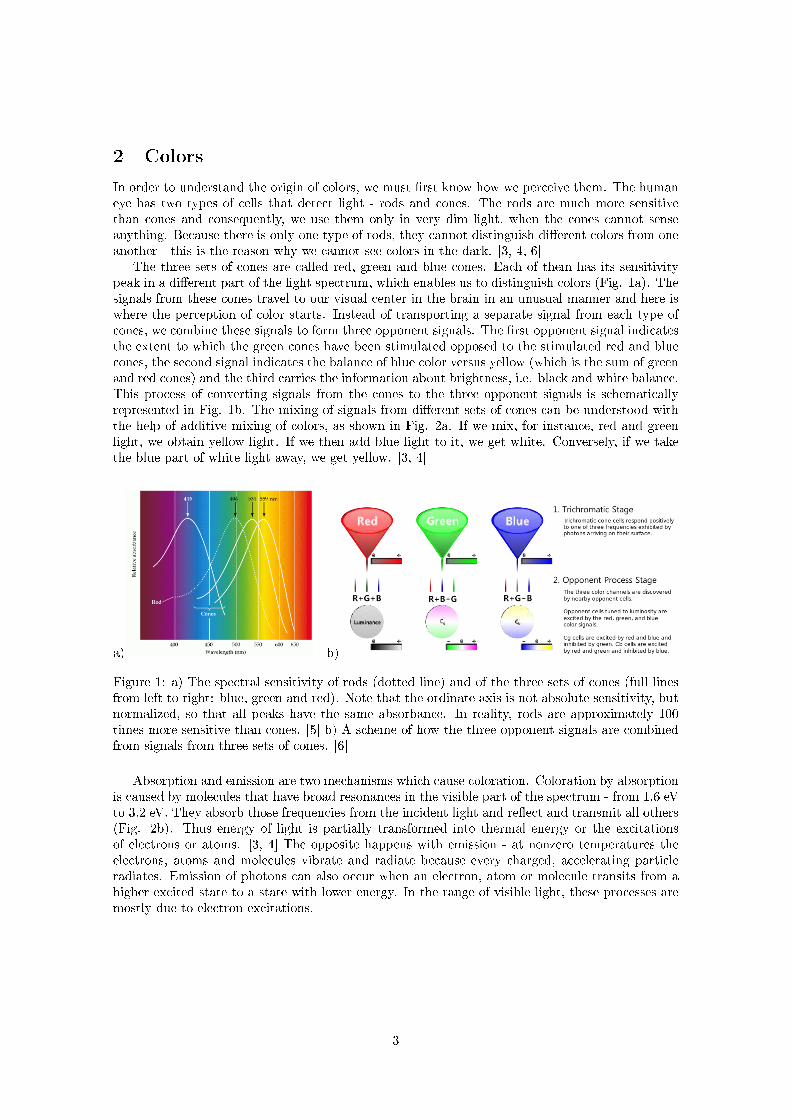
The three sets of cones are called red, green and blue cones. Each of them has its sensitivitypeak in a di�erent part of the light spectrum, which enables us to distinguish colors (Fig. 1a). Thesignals from these cones travel to our visual center in the brain in an unusual manner and here iswhere the perception of color starts. Instead of transporting a separate signal from each type ofcones, we combine these signals to form three opponent signals. The �rst opponent signal indicatesthe extent to which the green cones have been stimulated opposed to the stimulated red and bluecones, the second signal indicates the balance of blue color versus yellow (which is the sum of greenand red cones) and the third carries the information about brightness, i.e. black and white balance.This process of converting signals from the cones to the three opponent signals is schematicallyrepresented in Fig. 1b. The mixing of signals from di�erent sets of cones can be understood withthe help of additive mixing of colors, as shown in Fig. 2a. If we mix, for instance, red and greenlight, we obtain yellow light. If we then add blue light to it, we get white. Conversely, if we takethe blue part of white light away, we get yellow. [3, 4]
a) b)
Figure 1: a) The spectral sensitivity of rods (dotted line) and of the three sets of cones (full linesfrom left to right: blue, green and red). Note that the ordinate axis is not absolute sensitivity, butnormalized, so that all peaks have the same absorbance. In reality, rods are approximately 100times more sensitive than cones. [5] b) A scheme of how the three opponent signals are combinedfrom signals from three sets of cones. [6]
Absorption and emission are two mechanisms which cause coloration. Coloration by absorptionis caused by molecules that have broad resonances in the visible part of the spectrum - from 1.6 eVto 3.2 eV. They absorb those frequencies from the incident light and re�ect and transmit all others(Fig. 2b). Thus energy of light is partially transformed into thermal energy or the excitationsof electrons or atoms. [3, 4] The opposite happens with emission - at nonzero temperatures theelectrons, atoms and molecules vibrate and radiate because every charged, accelerating particleradiates. Emission of photons can also occur when an electron, atom or molecule transits from ahigher excited state to a state with lower energy. In the range of visible light, these processes aremostly due to electron excitations.
3
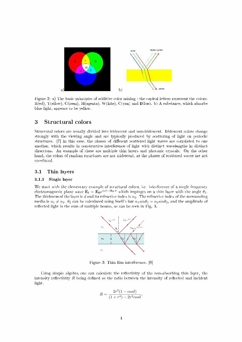
a) b)
Figure 2: a) The basic principles of additive color mixing - the capital letters represent the colors:R(ed), Y(ellow), G(reen), M(agenta), W(hite), C(yan) and B(lue). b) A substance, which absorbsblue light, appears to be yellow.
3 Structural colors
Structural colors are usually divided into iridescent and non-iridescent. Iridescent colors changestrongly with the viewing angle and are typically produced by scattering of light on periodicstructures. [7] In this case, the phases of di�erent scattered light waves are correlated to oneanother, which results in constructive interference of light with distinct wavelengths in distinctdirections. An example of these are multiple thin layers and photonic crystals. On the otherhand, the colors of random structures are not iridescent, as the phases of scattered waves are notcorrelated.
3.1 Thin layers
3.1.1 Single layer
We start with the elementary example of structural colors, i.e. interference of a single frequencyelectromagnetic plane wave Ei = E0e
iωt−ik0·r which impinges on a thin layer with the angle θ1.The thickness of the layer is d and its refractive index is n2. The refractive index of the surroundingmedia is n1 6= n2. θ2 can be calculated using Snell's law n1sinθ1 = n2sinθ2, and the amplitude ofre�ected light is the sum of multiple beams, as can be seen in Fig. 3.
Figure 3: Thin �lm interference. [8]
Using simple algebra one can calculate the re�ectivity of the non-absorbing thin layer, theintensity re�ectivity R being de�ned as the ratio between the intensity of re�ected and incidentlight.
R =2r2(1− cosδ)
(1 + r4)− 2r2cosδ,
4
r is the amplitude re�ectivity between the layer and the surrounding media and δ = k0 2n2 d cosθ2is the phase di�erence between the re�ected waves. Note that it is dependent not only on the char-acteristics of the thin layer but also on the wavelength of the incident wave λ0 = 2π
k0and the gazing
angle. This calculation is valid only in an idealized case when the incident light is completelycoherent - in reality, the coherence length of sunlight is approximately one wavelength. In thiscase, two waves do not interfere with each other if their di�erence in optical paths is larger than afew wavelengths. The joint intensity is then the sum of the intensities of separate waves.
Thin �lms have a metallic look because the re�ected light is directional and their color changesdepending on the viewing angle - this is called iridescence.
If the re�ectivity of such a system is fairly low, we can consider only the interference betweenthe two strongest wave fronts - the �rst is re�ected o� the �rst interface between the medium andair E0re
iωt and the second is transmitted through the medium, re�ected on the other side of thethin layer and then transmitted into the air E0trte
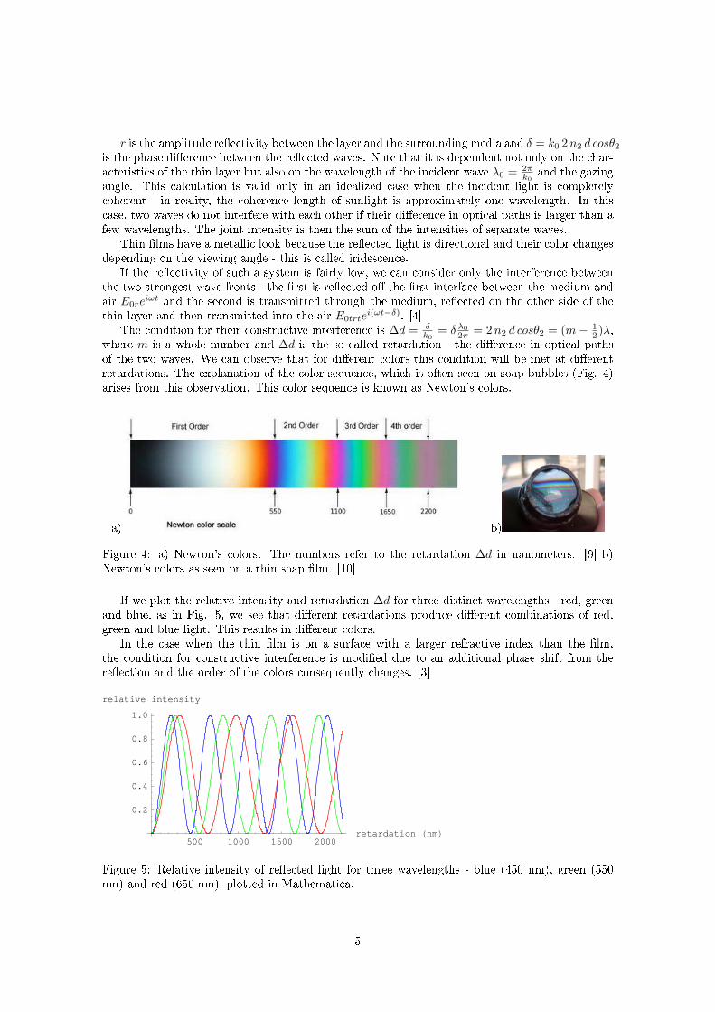
i(ωt−δ). [4]The condition for their constructive interference is ∆d = δ
k0= δ λ0
2π = 2n2 d cosθ2 = (m− 12 )λ,
where m is a whole number and ∆d is the so called retardation - the di�erence in optical pathsof the two waves. We can observe that for di�erent colors this condition will be met at di�erentretardations. The explanation of the color sequence, which is often seen on soap bubbles (Fig. 4)arises from this observation. This color sequence is known as Newton's colors.
a) b)
Figure 4: a) Newton's colors. The numbers refer to the retardation ∆d in nanometers. [9] b)Newton's colors as seen on a thin soap �lm. [10]
If we plot the relative intensity and retardation ∆d for three distinct wavelengths - red, greenand blue, as in Fig. 5, we see that di�erent retardations produce di�erent combinations of red,green and blue light. This results in di�erent colors.
In the case when the thin �lm is on a surface with a larger refractive index than the �lm,the condition for constructive interference is modi�ed due to an additional phase shift from there�ection and the order of the colors consequently changes. [3]
500 1000 1500 2000retardation HnmL
0.2
0.4
0.6
0.8
1.0
relative intensity
Figure 5: Relative intensity of re�ected light for three wavelengths - blue (450 nm), green (550nm) and red (650 nm), plotted in Mathematica.
5
3.1.2 Multiple layers
Multilayers are stacks of - in principle - di�erent single layers. In this case, the exact physicalformulation of light propagation is much more complex than it was in the previous section. Onemethod for calculating the re�ected or transmitted light is by using transfer matrices [2]. For eachlayer, a matrix is calculated which connects the electrical and magnetic �elds on both boundariesfor a certain polarization. Then, the matrices for all layers are multiplied and the total re�ectivityis calculated.
The other frequently used numerical method is the iterative method [2]. Here, two wave am-plitudes for each layer are de�ned - the waves travel perpendicularly to the boundary of the layersin opposite directions. Their amplitude is described with the re�ectance and transmittance of themedia, phase gain and the amplitudes of waves in the neighboring layers. From these equations, arecursive formula is derived which connects the re�ectivity of a layer with the re�ectivity of one ofits neighbors. Now, the overall re�ectivity can be calculated.
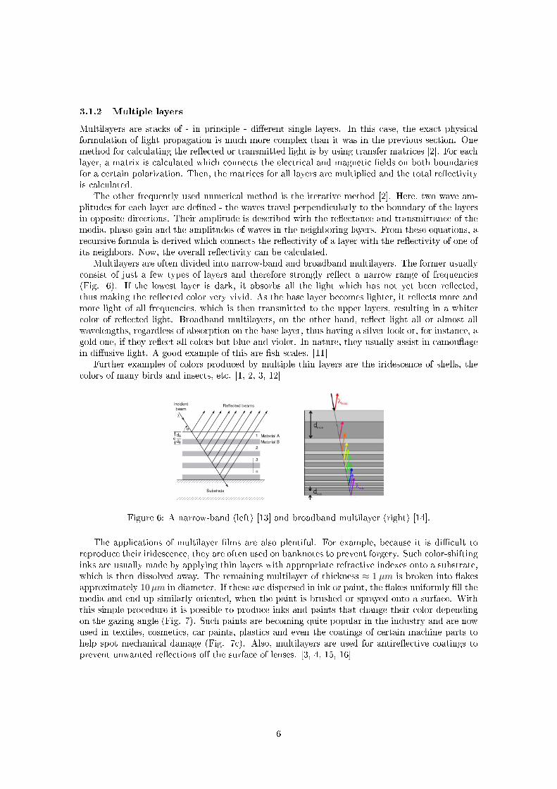
Multilayers are often divided into narrow-band and broadband multilayers. The former usuallyconsist of just a few types of layers and therefore strongly re�ect a narrow range of frequencies(Fig. 6). If the lowest layer is dark, it absorbs all the light which has not yet been re�ected,thus making the re�ected color very vivid. As the base layer becomes lighter, it re�ects more andmore light of all frequencies, which is then transmitted to the upper layers, resulting in a whitercolor of re�ected light. Broadband multilayers, on the other hand, re�ect light all or almost allwavelengths, regardless of absorption on the base layer, thus having a silver look or, for instance, agold one, if they re�ect all colors but blue and violet. In nature, they usually assist in camou�agein di�usive light. A good example of this are �sh scales. [11]
Further examples of colors produced by multiple thin layers are the iridescence of shells, thecolors of many birds and insects, etc. [1, 2, 3, 12]
Figure 6: A narrow-band (left) [13] and broadband multilayer (right) [14].
The applications of multilayer �lms are also plentiful. For example, because it is di�cult toreproduce their iridescence, they are often used on banknotes to prevent forgery. Such color-shiftinginks are usually made by applying thin layers with appropriate refractive indexes onto a substrate,which is then dissolved away. The remaining multilayer of thickness ≈ 1 µm is broken into �akesapproximately 10µm in diameter. If these are dispersed in ink or paint, the �akes uniformly �ll themedia and end up similarly oriented, when the paint is brushed or sprayed onto a surface. Withthis simple procedure it is possible to produce inks and paints that change their color dependingon the gazing angle (Fig. 7). Such paints are becoming quite popular in the industry and are nowused in textiles, cosmetics, car paints, plastics and even the coatings of certain machine parts tohelp spot mechanical damage (Fig. 7c). Also, multilayers are used for antire�ective coatings toprevent unwanted re�ections o� the surface of lenses. [3, 4, 15, 16]
6
(a) (b) (c)
Figure 7: Color shifting ink changes its color depending on the viewing angle. Selected examplesinclude color shifting ink, used (a) against counterfeit [17], (b) for decoration [18], and (c) onmachine parts to help spot mechanical damage [19].
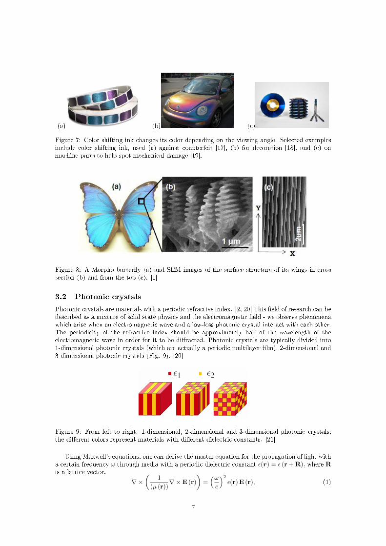
Figure 8: A Morpho butter�y (a) and SEM images of the surface structure of its wings in crosssection (b) and from the top (c). [1]
3.2 Photonic crystals
Photonic crystals are materials with a periodic refractive index. [2, 20] This �eld of research can bedescribed as a mixture of solid state physics and the electromagnetic �eld - we observe phenomenawhich arise when an electromagnetic wave and a low-loss photonic crystal interact with each other.The periodicity of the refractive index should be approximately half of the wavelength of theelectromagnetic wave in order for it to be di�racted. Photonic crystals are typically divided into1-dimensional photonic crystals (which are actually a periodic multilayer �lm), 2-dimensional and3-dimensional photonic crystals (Fig. 9). [20]
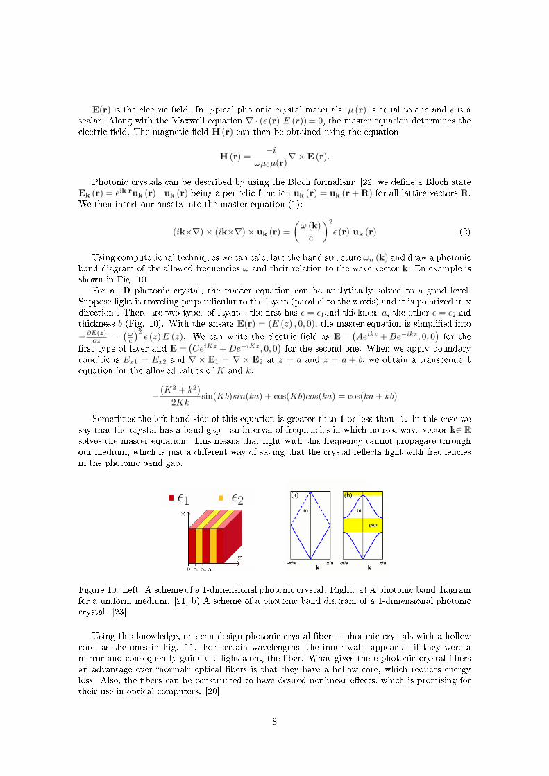
Figure 9: From left to right: 1-dimensional, 2-dimensional and 3-dimensional photonic crystals;the di�erent colors represent materials with di�erent dielectric constants. [21]
Using Maxwell's equations, one can derive the master equation for the propagation of light witha certain frequency ω through media with a periodic dielectric constant ε(r) = ε (r + R), where Ris a lattice vector.
∇×(
1
(µ (r))∇×E (r)
)=
(ωc
)2
ε(r)E (r), (1)
7
E(r) is the electric �eld. In typical photonic crystal materials, µ (r) is equal to one and ε is ascalar. Along with the Maxwell equation ∇ · (ε (r) E (r)) = 0, the master equation determines theelectric �eld. The magnetic �eld H (r) can then be obtained using the equation
H (r) =−i
ωµ0µ(r)∇×E (r).
Photonic crystals can be described by using the Bloch formalism: [22] we de�ne a Bloch stateEk (r) = eik·ruk (r) , uk (r) being a periodic function uk (r) = uk (r + R) for all lattice vectors R.We then insert our ansatz into the master equation (1):
(ik×∇)× (ik×∇)× uk (r) =
(ω (k)
c
)2
ε (r) uk (r) (2)
Using computational techniques we can calculate the band structure ωn (k) and draw a photonicband diagram of the allowed frequencies ω and their relation to the wave vector k. En example isshown in Fig. 10.
For a 1D photonic crystal, the master equation can be analytically solved to a good level.Suppose light is traveling perpendicular to the layers (parallel to the z axis) and it is polarized in xdirection . There are two types of layers - the �rst has ε = ε1and thickness a, the other ε = ε2andthickness b (Fig. 10). With the ansatz E(r) = (E (z) , 0, 0), the master equation is simpli�ed into
−∂E(z)∂z =
(ωc
)2ε (z)E (z). We can write the electric �eld as E =
(Aeikz +Be−ikz, 0, 0
)for the
�rst type of layer and E =(CeiKz +De−iKz, 0, 0
)for the second one. When we apply boundary
conditions Ex1 = Ex2 and ∇ × E1 = ∇ × E2 at z = a and z = a + b, we obtain a transcendentequation for the allowed values of K and k.
− (K2 + k2)
2Kksin(Kb)sin(ka) + cos(Kb)cos(ka) = cos(ka+ kb)
Sometimes the left hand side of this equation is greater than 1 or less than -1. In this case wesay that the crystal has a band gap - an interval of frequencies in which no real wave vector k∈ Rsolves the master equation. This means that light with this frequency cannot propagate throughour medium, which is just a di�erent way of saying that the crystal re�ects light with frequenciesin the photonic band gap.
Figure 10: Left: A scheme of a 1-dimensional photonic crystal. Right: a) A photonic band diagramfor a uniform medium. [21] b) A scheme of a photonic band diagram of a 1-dimensional photoniccrystal. [23]
Using this knowledge, one can design photonic-crystal �bers - photonic crystals with a hollowcore, as the ones in Fig. 11. For certain wavelengths, the inner walls appear as if they were amirror and consequently guide the light along the �ber. What gives these photonic crystal �bersan advantage over �normal� optical �bers is that they have a hollow core, which reduces energyloss. Also, the �bers can be constructed to have desired nonlinear e�ects, which is promising fortheir use in optical computers. [20]
8
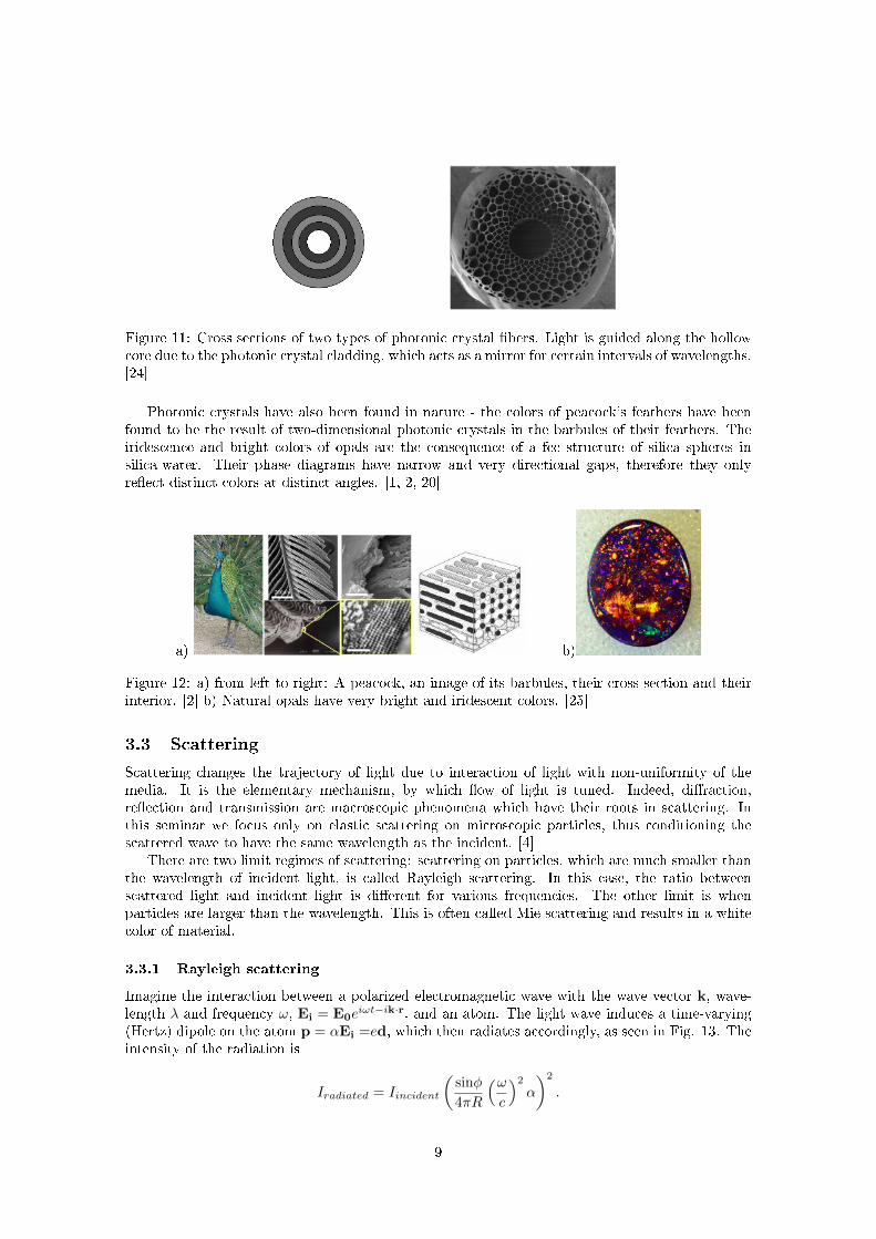
Figure 11: Cross sections of two types of photonic crystal �bers. Light is guided along the hollowcore due to the photonic crystal cladding, which acts as a mirror for certain intervals of wavelengths.[24]
Photonic crystals have also been found in nature - the colors of peacock's feathers have beenfound to be the result of two-dimensional photonic crystals in the barbules of their feathers. Theiridescence and bright colors of opals are the consequence of a fcc structure of silica spheres insilica-water. Their phase diagrams have narrow and very directional gaps, therefore they onlyre�ect distinct colors at distinct angles. [1, 2, 20]
a) b)
Figure 12: a) from left to right: A peacock, an image of its barbules, their cross section and theirinterior. [2] b) Natural opals have very bright and iridescent colors. [25]
3.3 Scattering
Scattering changes the trajectory of light due to interaction of light with non-uniformity of themedia. It is the elementary mechanism, by which �ow of light is tuned. Indeed, di�raction,re�ection and transmission are macroscopic phenomena which have their roots in scattering. Inthis seminar we focus only on elastic scattering on microscopic particles, thus conditioning thescattered wave to have the same wavelength as the incident. [4]
There are two limit regimes of scattering: scattering on particles, which are much smaller thanthe wavelength of incident light, is called Rayleigh scattering. In this case, the ratio betweenscattered light and incident light is di�erent for various frequencies. The other limit is whenparticles are larger than the wavelength. This is often called Mie scattering and results in a whitecolor of material.
3.3.1 Rayleigh scattering
Imagine the interaction between a polarized electromagnetic wave with the wave vector k, wave-length λ and frequency ω, Ei = E0e
iωt−ik·r, and an atom. The light wave induces a time-varying(Hertz) dipole on the atom p = αEi =ed, which then radiates accordingly, as seen in Fig. 13. Theintensity of the radiation is
Iradiated = Iincident
(sinφ
4πR
(ωc
)2
α
)2
.
9
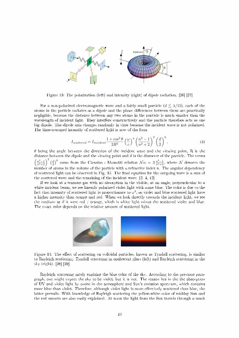
Figure 13: The polarization (left) and intensity (right) of dipole radiation. [26] [27]
For a non-polarized electromagnetic wave and a fairly small particle (d . λ/15), each of theatoms in the particle radiates as a dipole and the phase di�erences between them are practicallynegligible, because the distance between any two atoms in the particle is much smaller than thewavelength of incident light. They interfere constructively and the particle therefore acts as onebig dipole. The dipole axis changes randomly in time because the incident wave is not polarized.The time-averaged intensity of scattered light is now of the form
Iscattered = Iincident1 + cos2 θ
2R2
(ωc
)4(n2 − 1
n2 + 2
)2 (d
2
)6
, (3)
θ being the angle between the direction of the incident wave and the viewing point, R is thedistance between the dipole and the viewing point and d is the diameter of the particle. The terms(n2−1n2+2
)2 (d2
)6come from the Clausius - Mossotti relation Nα = 3 n2−1
n2+2 , where N denotes the
number of atoms in the volume of the particle with a refractive index n. The angular dependencyof scattered light can be observed in Fig. 15. The �nal equation for the outgoing wave is a sum ofthe scattered wave and the remaining of the incident wave. [2, 4, 12]
If we look at a tenuous gas with no absorption in the visible, at an angle, perpendicular to awhite incident beam, we see linearly polarized violet light with some blue. The color is due to thefact that intensity of scattered light is proportionate to ω4, so violet and blue scattered light havea higher intensity than orange and red. When we look directly towards the incident light, we seethe medium as if it were red / orange, which is white light minus the scattered violet and blue.The exact color depends on the relative amount of scattered light.
Figure 14: The e�ect of scattering on colloidal particles, known as Tyndall scattering, is similarto Rayleigh scattering. Tyndall scattering in opalescent glass (left) and Rayleigh scattering in thesky (right). [28] [29]
Rayleigh scattering nicely explains the blue color of the sky. According to the previous para-graph, one might expect the sky to be violet, but it is not. The reason lies in the the absorptionof UV and violet light by ozone in the atmosphere and Sun's emission spectrum, which containsmore blue than violet. Therefore, although violet light is more e�ectively scattered than blue, thelatter prevails. With knowledge of Rayleigh scattering the yellow-white color of midday Sun andthe red sunsets are also easily explained. At noon the light from the Sun travels through a much
10
thinner layer of air than at sunset, so less blue and UV light are scattered and more of them reachthe viewer. This results in a yellow hue, opposed to a red hue at sunsets. [3]
The greater the concentration of microscopic particles, the greater is the likelihood of scattering.This is why redder sunsets are seen after major volcanic eruptions or where the air is more pollutedwith particles, smaller than 100 nm (so called ultra-�ne particles).
3.3.2 Mie scattering
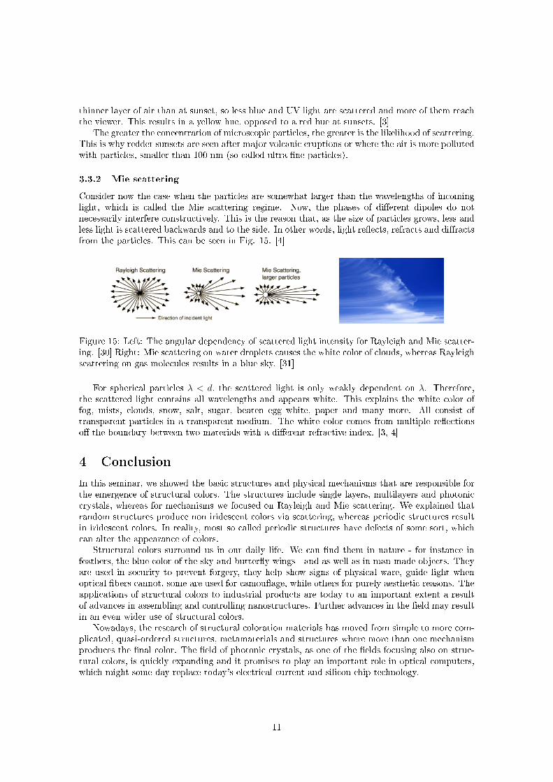
Consider now the case when the particles are somewhat larger than the wavelengths of incominglight, which is called the Mie scattering regime. Now, the phases of di�erent dipoles do notnecessarily interfere constructively. This is the reason that, as the size of particles grows, less andless light is scattered backwards and to the side. In other words, light re�ects, refracts and di�ractsfrom the particles. This can be seen in Fig. 15. [4]
Figure 15: Left: The angular dependency of scattered light intensity for Rayleigh and Mie scatter-ing. [30] Right: Mie scattering on water droplets causes the white color of clouds, whereas Rayleighscattering on gas molecules results in a blue sky. [31]
For spherical particles λ < d, the scattered light is only weakly dependent on λ. Therefore,the scattered light contains all wavelengths and appears white. This explains the white color offog, mists, clouds, snow, salt, sugar, beaten egg white, paper and many more. All consist oftransparent particles in a transparent medium. The white color comes from multiple re�ectionso� the boundary between two materials with a di�erent refractive index. [3, 4]
4 Conclusion
In this seminar, we showed the basic structures and physical mechanisms that are responsible forthe emergence of structural colors. The structures include single layers, multilayers and photoniccrystals, whereas for mechanisms we focused on Rayleigh and Mie scattering. We explained thatrandom structures produce non iridescent colors via scattering, whereas periodic structures resultin iridescent colors. In reality, most so called periodic structures have defects of some sort, whichcan alter the appearance of colors.
Structural colors surround us in our daily life. We can �nd them in nature - for instance infeathers, the blue color of the sky and butter�y wings - and as well as in man-made objects. Theyare used in security to prevent forgery, they help show signs of physical ware, guide light whenoptical �bers cannot, some are used for camou�age, while others for purely aesthetic reasons. Theapplications of structural colors to industrial products are today to an important extent a resultof advances in assembling and controlling nanostructures. Further advances in the �eld may resultin an even wider use of structural colors.
Nowadays, the research of structural coloration materials has moved from simple to more com-plicated, quasi-ordered structures, metamaterials and structures where more than one mechanismproduces the �nal color. The �eld of photonic crystals, as one of the �elds focusing also on struc-tural colors, is quickly expanding and it promises to play an important role in optical computers,which might some day replace today's electrical current and silicon chip technology.
11
References
[1] A. Saito, Sci. Technol. Adv. Mater. 12, 064709 (2011)
[2] S. Kinoshita, Structural Colors in the Realm of Nature (World scienti�c Publishing, Singapore, 2008).
[3] K. Nassau, The Physics and Chemistry of Color (Wiley series in pure and applied optics, USA, 2001)
[4] E. Hecht, Optics (Addison Wesley, San Francisco, 2002)
[5] http://openwetware.org/wiki/BIO254:Phototransduction (27.11.2013)
[6] http://en.wikipedia.org/wiki/Color_vision (29.11.2013)
[7] H. Noh et al., Adv. Matter 22, 2871-2880 (2010)
[8] modi�ed from http://en.wikipedia.org/wiki/ File:Thin_�lm_interference_-_soap_bubble.gif(29.11.2013)
[9] http://gemologyproject.com/wiki/index.php?title=Polariscope (28.11.2013)
[10] http://laser.physics.sunysb.edu/~ett/pictures/809.jpg (30.11.2013)
[11] A. R. Parker, Phil. Trans. R. Soc. A 364, 1759�1782 (2009)
[12] http://www.itp.uni-hannover.de/~zawischa/ITP/origins.html#uebersicht (30.11.2013)
[13] http://xdb.lbl.gov/Section4/Sec_4-1.html (29.11.2013)
[14] http://www.cesr.fr/~pvb/gamma_wave_2005/focusing.html (29.11.2013)
[15] A. R. Parker, Materialstoday Sept.: 26-31 (2002)
[16] http://www.jdsu.com/ProductLiterature/chroma�air-ds-ccs-ae.pdf (29.11.2013)
[17] http://graphics.kodak.com/AU/en/Product/Security_Authentication/Products/Color_Shifting_Ink/default.htm(28.11.2013)
[18] http://volkswagenutah.wordpress.com/2013/01/03/chroma�air-volkswagen-style/ (29/11/2013)
[19] http://www.ijs.si/ctp/ (1.12.2013)
[20] J. D. Joannopoulos, S. G. Johnson, J. N. Winn, R. D. Meade, Photonic crystals (Princeton universitypress, printed in Singapore, 2008)
[21] modi�ed from http://ab-initio.mit.edu/photons/tutorial/ (30.11.2013)
[22] C. Kittel, Introduction to Solid State Physics (John Wiley & Sons, USA, 2005)
[23] http://large.stanford.edu/courses/2007/ap273/dai1/ (08.12.2013)
[24] http://spie.org/x35457.xml?pf=true&ArticleID=x35457 (30.11.2013)
[25] http://www.blackopalworld.com/black-opal-590ct-p-165.html?osCsid=39ed1f25c49c69dd90928ed0aa279�d(30.11.2013)
[26] http://www.sparknotes.com/physics/optics/phenom/section3.rhtml (28.11.2013)
[27] http://people.seas.harvard.edu/~jones/es151/prop_models/propagation.html (30.11.2013)
[28] http://en.wikipedia.org/wiki/Opalescence (28.11.2013)
[29] http://en.wikipedia.org/wiki/File:SDIM0241b.jpg (30.11.2013)
[30] http://hyperphysics.phy-astr.gsu.edu/hbase/atmos/blusky.html (28.11.2013)
[31] http://www.background-free.com/landscapes/clouds/clouds_white.jpg.html (1.12.2013)
12