Embed Size (px)
Citation preview
Bunsenstraße 1, D-24145 KielTel. +49 (0)431 - 65 02 77 Fax +49 (0)431 - 65 05 11e-mail: [email protected]
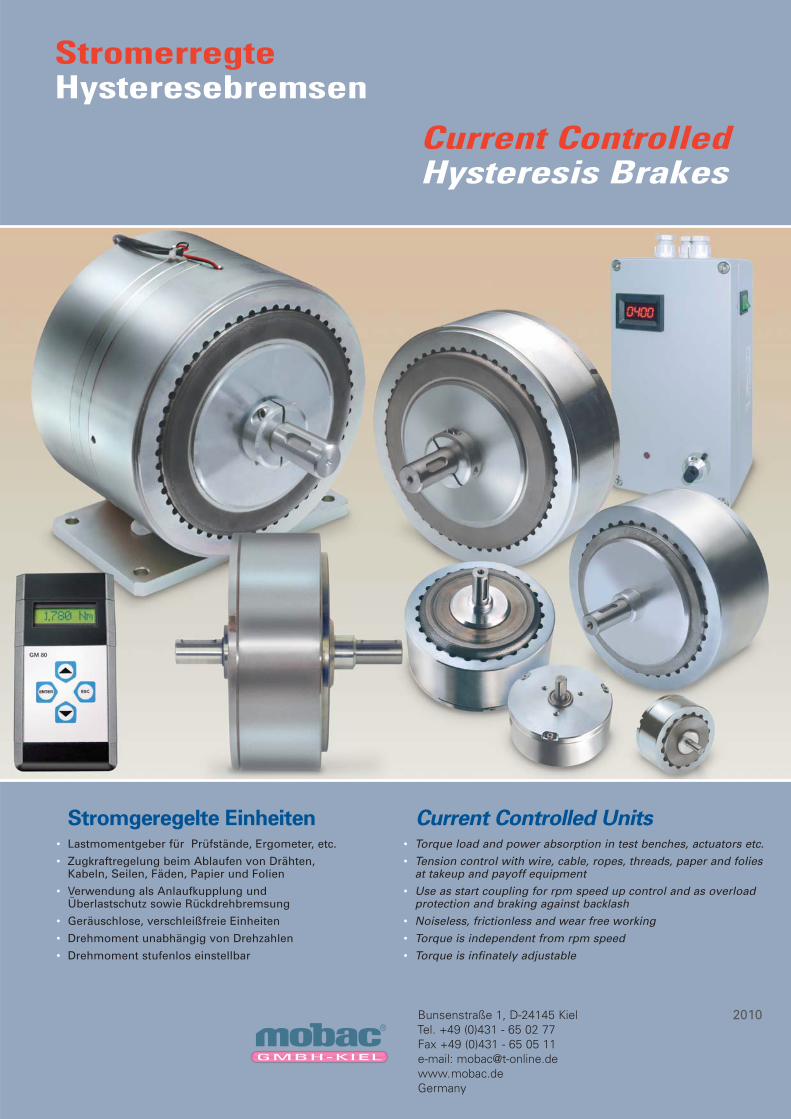
StromerregteHysteresebremsen
Current ControlledHysteresis Brakes
• Lastmomentgeber für Prüfstände, Ergometer, etc.
• Zugkraftregelung beim Ablaufen von Drähten, Kabeln, Seilen, Fäden, Papier und Folien
• Verwendung als Anlaufkupplung und Überlastschutz sowie Rückdrehbremsung
• Geräuschlose, verschleißfreie Einheiten
• Drehmoment unabhängig von Drehzahlen
• Drehmoment stufenlos einstellbar
• Torque load and power absorption in test benches, actuators etc.
• Tension control with wire, cable, ropes, threads, paper and folies at takeup and payoff equipment
• Use as start coupling for rpm speed up control and as overload protection and braking against backlash
• Noiseless, frictionless and wear free working
• Torque is independent from rpm speed
• Torque is infinately adjustable
2010
Stromgeregelte Einheiten Current Controlled Units

2 GmbH · Bunsenstraße 1 · D-24145 Kiel · Phone +49 (0)431-65 02 77 · Fax +49 (0)431-65 05 11 · E-mail: [email protected]®
Anwendungensbeispiel Applications
Hysteresebremsen sorgen für einegenaue Zugregelung während desWickelprozesses und der Intervallean schnellen Wickelautomaten.
Hysteresis Brakes provide precisecontrol of wire tension during wind,hook and cut operation of highspeed automated windingmachines.
Bei Spulen- und Transformatorwickelmaschinen werdenHysteresebremsen eingesetzt, um eine genaue Zugregelungwährend des Wickelprozesses zu gewährleisten.
Transformer and coil winding operations employing HysteresisBrakes in open loop control for maintaining precise tensionduring winding process.
Anwendungsbeispiel einer Hysteresebremse mit großerBohrung: Die Einheit ist verbunden mit einem Abwickelflyerum Drähte überkopf zuggeregelt von Spulen abzuziehen.
Application of a Hysteresis Brake with large bore: The brakepole case is bolted to the machine frame and a hollow shaft,with bearings, is mounted in the pole. The hollow shaft, rotorand flyer form one assembly to tension the winding material.
WickelproduktWinding product
WickelgutWound coil
Potentiometer
TastarmFollower arm
Steuerung/StromversorgungController/Power supply
AblaufspuleWire spool
HysteresebremseHysteresis Brake
HysteresebremseHysteresis Brake
Hysterese-bremse
HysteresisBrake
HysteresebremseHysteresis Brake
SteuerungControl panel
DrahtvorratWire magazine Drahtvorrat
Wire magazine
Unabhängig von der Regelart (Tänzerrolle, Tastarm, Fotozelleoder Ultraschall-Sensor) werden Hysteresebremsen stets alsbeste Lösung für eine Zugregelung eingesetzt.
Regardless of control scheme (dancer arm, photo or ultrasonicsensors), Hysteresis Brakes provide the ultimate in tensioncontrol devices.
Anwendung von Hysteresebremsen bei der Simulierung vonDrehmomenten für z.B. Lebensdauertests von Elektromotoren,Getrieben und vielen anderen rotierenden Einheiten und Anlagen.
Hysteresis Brakes are widely used in load simulation applications for life testing on electric motors, actuators, small gas engines,gearboxes, and many other rotating devices and assemblies.
Hysteresebremsen/Hysteresis Brakes
Motoren/Motors
3GmbH · Bunsenstraße 1 · D-24145 Kiel · Phone +49 (0)431-65 02 77 · Fax +49 (0)431-65 05 11 · E-mail: [email protected]®
LebensdauerLängere Lebensdauererwartung: Hysteresebremsen und -kupplungenerzeugen ein Drehmoment stets über einen Luftspalt. Dies unterscheidetsie absolut von Reibbelagbremsen und Magnetpulvereinheiten. Es gibtaus dem o. g. Grund also keinen Verschleiß und auch keine Dichtungs-probleme. Hysteresebremsen und -kupplungen haben deshalb eine umein Vielfaches höhere Lebenserwartung.
Drehmoment WiederholgenauigkeitBeste Drehmoment Wiederholgenauigkeit: Da das Drehmoment magne-tisch ohne Berührung von Materialien erzeugt wird, ermöglichen Hys-teresebremsen und -kupplungen eine hohe Drehmoment Wiederhol-genauigkeit. Reibbelagbremsen und Magnetpulverbremsen sindnormalerweise einem mehr oder minder hohen Verschleiß unterworfen,mit der Folge, dass Wiederholgenauigkeit verlorengeht.
SchlupfgeschwindigkeitHöchste Geschwindigkeitsmöglichkeiten: Hysteresebremsen ermög-lichen die höchsten Schlupfgeschwindigkeiten aller elektrischen Dreh-momentübertragungsvarianten. Je nach Baugröße, Verlustleistung undLagerbeanspruchung können oft Drehzahlen weit über 10000 min-1
erreicht werden. Dazu kommt, dass das volle Drehmoment auch ohneSchlupfdrehzahl anliegt und sehr sanft bei jeder Drehzahl übertragen wird.
SanftlaufDa bei Hysteresebremsen keine mechanische Reibung und auch keinMagnetpulver beteiligt ist, arbeiten diese Einheiten besonders sanft, ganz gleich wie hoch die anteilige Schlupfdrehzahl ist. Dies wird bei denmeisten Anwendungen wie Zugregelung in der Verpackungsindustrieoder bei Kraftübertragungen in der Antriebstechnik als Vorteil angesehen.
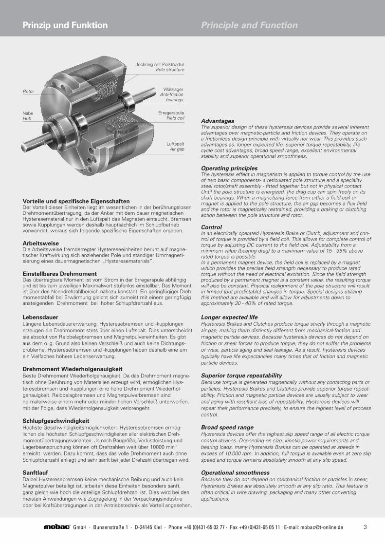
Vorteile und spezifische EigenschaftenDer Vorteil dieser Einheiten liegt im wesentlichen in der berührungslosenDrehmomentübertragung, da der Anker mit dem dauer magnetischenHysteresematerial nur in den Luftspalt des Magneten eintaucht. Bremsensowie Kupplungen werden deshalb hauptsächlich im Schlupfbetriebverwendet, woraus sich folgende spezifische Eigenschaften ergeben.
ArbeitsweiseDie Arbeitsweise fremderregter Hystereseeinheiten beruht auf magne-tischer Kraftwirkung sich anziehender Pole und ständiger Ummagneti-sierung eines dauermagnetischen „Hysteresematerials“.
Einstellbares DrehmomentDas übertragbare Moment ist vom Strom in der Erregerspule abhängigund ist bis zum jeweiligen Maximalwert stufenlos einstellbar. Das Momentist über den Nenndrehzahlbereich nahezu konstant. Ein geringfügiger Dreh-momentabfall bei Erwärmung gleicht sich zumeist mit einem geringfügigansteigenden Drehmoment bei hoher Schlupfdrehzahl aus.
Prinzip und Funktion
Rotor
NabeHub
LuftspaltAir gap
AdvantagesThe superior design of these hysteresis devices provide several inherentadvantages over magnetic-particle and friction devices. They operate on a frictionless design principle with virtually nor wear. This provides suchadvantages as: longer expected life, superior torque repeatability, lifecycle cost advantages, broad speed range, excellent environmentalstability and superior operational smoothness.
Operating principlesThe hysteresis effect in magnetism is applied to torque control by the useof two basic components- a reticulated pole structure and a specialitysteel rotor/shaft assembly - fitted together but not in physical contact.Until the pole structure is energized, the drag cup can spin freely on itsshaft bearings. When a magnetizing force from either a field coiI ormagnet is applied to the pole structure, the air gap becomes a flux fieldand the rotor is magnetically restrained, providing a braking or clutchingaction between the pole structure and rotor.
ControlIn an electrically operated Hysteresis Brake or Clutch, adjustment and con-trol of torque is provided by a field coil. This allows for complete control oftorque by adjusting DC current to the field coil. Adjustability from aminimum value (bearing drag) to a maximum value of 15 - 35% aboverated torque is possible.In a permanent magnet device, the field coil is replaced by a magnetwhich provides the precise field strength necessary to produce ratedtorque without the need of electrical excitation. Since the field strengthproduced by a permanent magnet is a constant value, the resulting torquewill also be constant. Physical realignment of the pole structure will resultin limited (but predictable) changes in torque. Special designs utilizingthis method are available and will allow for adjustments down toapproximately 30 - 40% of rated torque.
Principle and Function
Longer expected lifeHysteresis Brakes and Clutches produce torque strictly through a magneticair gap, making them distinctly different from mechanical-friction andmagnetic partide devices. Because hysteresis devices do not depend onfriction or shear forces to produce torque, they do not suffer the problemsof wear, particle aging and seal leakage. As a result, hysteresis devicestypically have life expectancies many times that of friction and magneticparticle devices.
Superior torque repeatabilityBecause torque is generated magnetically without any contacting parts orparticles, Hysteresis Brakes and Clutches provide superior torque repeat-ability. Friction and magnetic particle devices are usually subject to wearand aging with resultant loss of repeatability. Hysteresis devices willrepeat their performance precisely, to ensure the highest level of processcontrol.
Broad speed rangeHysteresis devices offer the highest slip speed range of all electric torquecontrol devices. Depending on size, kinetic power requirements andbearing loads, many Hysteresis Brakes can be operated at speeds inexcess of 10.000 rpm. In addition, full torque is available even at zero slipspeed and torque remains absolutely smooth at any slip speed.
Operational smoothness Because they do not depend on mechanical friction or particles in shear,Hysteresis Brakes are absolutely smooth at any slip ratio. This feature isoften critical in wire drawing, packaging and many other convertingapplications.
Jochring mit PolstrukturPole structure
WälzlagerAnti-friction
bearings
ErregerspuleField coil

4 GmbH · Bunsenstraße 1 · D-24145 Kiel · Phone +49 (0)431-65 02 77 · Fax +49 (0)431-65 05 11 · E-mail: [email protected]®
Stromerregte Hysteresebremsen Standard
mit beidseitiger Welle
Current Controlled Hysteresis Brakes
Standard with shafts on both sides
b
ca ØB
d
Type a b c d ØBh6
HB- 250M-2DS 20 4,0 3,5 2,5 12HB- 450M-2DS 20 5,0 3,5 3,1 15HB- 750M-2DS 20 5,0 9,0 3,1 17HB-1750M-2DS 25 8,0 12,5 4,0 25HB-3500M-2DS 25 8,0 12,5 4,0 25
*PassfedernutKeyway
Type ØA ØBh6 ØCh6 E F H I K ØL M N
31,8 3,00 10,00 2,0 18,6 8,0 24,0 M2,5 x 4 19,0 --- ---45,7 5,00 14,00 2,4 20,7 12,1 24,7 M2,5 x 5 19,0 9,5 0,750,0 5,00 14,00 2,5 23,5 13,0 27,3 M3 x 6 21,0 9,5 0,760,0 7,00 17,00 2,0 39,9 15,0 42,8 M4 x 8 25,0 10,0 0,792,0 10,00 22,00 2,5 39,0 25,0 50,8 M4 x 9 38,0 16,0 1,0
112,5 12,00 28,00 4,0 50,5 27,0 64,3 M5 x 10 45,0 137,5 15,00 32,00 3,5 52,4 27,0 73,0 M5 x 10 60,0 158,0 17,00 35,00 4,5 73,0 38,0 95,0 M6 x 12 70,0 226,0 25,00 52,00 6,0 76,2 50,0 107,0 M6 x 12 100,0 226,0 25,00 - - 152,4 50,0 214,0
Abmessungen / Dimensions (mm)
*Passfedernut s.untenKeyway see below
HB- 3M-2DSHB- 10M-2DSHB- 20M-2DSHB- 50M-2DSHB- 140M-2DSHB- 250M-2DSHB- 450M-2DSHB- 750M-2DSHB-1750M-2DSHB-3500M-2DS
Type Moment bei Arbeitsstrom Widerstand bei Spannung Drehzahl mögliche Verlustleistung Restmoment Trägheitsmoment GewichtArbeitsstrom Possible dissipation ohne Strom
Torque at Working current Resistance at Voltage rpm (Watt) Residual torque Rotor inertia Weightworking current 25°C±10% max. 25°C±10% unterbrochen kontinuierlich without Current
(Nm) I 1 (mA) (Ohm) V DC bei/at I 1 (min-1) non continuous continuous (Nm) (kgcm2) (kg)
0,024 155 171 25 20000 20 5 3,53 x 10⁻⁴ 0,0043 0,1030,095 143 180 24 20000 35 8 7,06 x 10⁻⁴ 0,0435 0,2380,150 232 120 24 20000 50 12 7,77 x 10⁻⁴ 0,0458 0,3240,380 270 95 24 15000 90 23 1,55 x 10⁻³ 0,1670 0,7641,200 270 95 24 12000 300 75 5,42 x 10⁻³ 1,0000 1,8502,100 289 96 24 10000 450 110 7,77 x 10⁻³ 3,4500 3,5003,600 473 50 24 8000 670 160 1,51 x 10⁻² 7,5000 5,600 5,800 410 60 23 6000 1000 200 5,00 x 10⁻² 14,5000 10,200
14,500 535 52 26 6000 2400 350 9,18 x 10⁻² 62,5000 24,50029,000 1070 26 26 6000 4800 600 1,36 x 10⁻¹ 125,0000 49,750
Technische Daten / Technical Data
HB- 3M-2DSHB- 10M-2DSHB- 20M-2DSHB- 50M-2DSHB- 140M-2DSHB- 250M-2DSHB- 450M-2DSHB- 750M-2DSHB-1750M-2DSHB-3500M-2DS
E
A C B
FI
3x120°
K
LHH
MM
N
N
Grundplatte 216 X 130 (t=12)

5GmbH · Bunsenstraße 1 · D-24145 Kiel · Phone +49 (0)431-65 02 77 · Fax +49 (0)431-65 05 11 · E-mail: [email protected]®
E
A C B
FI
3x120°
KLH
D
M
NType ØA ØBh6 ØCh6 D E F H I K ØL M N
HB- 3M-2 31,8 3,00 10,00 1,0 2,0 18,6 8,0 23,6 M2,5 x 4 19,0 --- ---HB- 10M-2 45,7 5,00 14,00 2,0 2,4 20,7 12,7 24,7 M2,5 x 5 19,0 9,5 0,7HB- 20M-2 50,0 5,00 14,00 2,0 2,5 23,5 13,0 26,5 M3 x 6 21,0 9,5 0,7HB- 50M-2 60,0 7,00 17,00 2,0 2,0 39,7 15,0 42,8 M4 x 8 25,0 10,0 0,7HB- 140M-2 92,0 10,00 22,00 2,5 2,5 39,0 25,0 50,8 M4 x 9 38,0 16,0 1,0HB- 250M-2 112,5 12,00 28,00 2,5 4,0 50,5 27,0 64,3 M5 x 10 45,0 HB- 450M-2 137,5 15,00 32,00 2,5 3,5 52,4 27,0 73,0 M5 x 10 60,0 HB- 750M-2 158,0 17,00 35,00 2,5 4,5 73,0 38,0 95,0 M6 x 12 70,0 HB-1750M-2 226,0 25,00 52,00 3,5 6,0 76,2 50,0 107,0 M6 x 12 100,0 HB-3500M-2 226,0 25,00 - - - 152,4 50,0 214,0 Grundplatte 216 X 130 (t=12)
Type Moment bei Arbeitsstrom Widerstand bei Spannung Drehzahl mögliche Verlustleistung Restmoment Trägheitsmoment GewichtArbeitsstrom Possible dissipation ohne Strom
Torque at Working current Resistance at Voltage rpm (Watt) Residual torque Rotor inertia Weightworking current 25°C±10% max. 25°C±10% unterbrochen kontinuierlich without Current
(Nm) I 1 (mA) (Ohm) V DC bei/at I 1 (min-1) non continuous continuous (Nm) (kgcm2) (kg)
0,024 155 171 25 20000 20 5 3,53 x 10⁻⁴ 0,0043 0,1010,095 143 180 24 20000 35 8 7,06 x 10⁻⁴ 0,0435 0,2340,150 232 120 24 20000 50 12 7,77 x 10⁻⁴ 0,0458 0,3200,380 270 95 24 15000 90 23 1,55 x 10⁻³ 0,1670 0,7551,200 270 95 24 12000 300 75 5,42 x 10⁻³ 1,0000 1,8402,100 289 96 24 10000 450 110 7,77 x 10⁻³ 3,4500 3,4003,600 473 50 24 8000 670 160 1,51 x 10⁻² 7,5000 5,600 5,800 410 60 23 6000 1000 200 5,00 x 10⁻² 14,5000 10,100
14,500 535 52 26 6000 2400 350 9,18 x 10⁻² 62,5000 24,40029,000 1070 26 26 6000 4800 600 1,36 x 10⁻¹ 125,0000 49,600
Abmessungen / Dimensions (mm)
Technische Daten / Technical Data
b
ca ØB
d
Type a b c d ØBh6
HB- 250M-2 20 4,0 3,5 2,5 12HB- 450M-2 20 5,0 3,5 3,1 15HB- 750M-2 20 5,0 9,0 3,1 17HB-1750M-2 25 8,0 12,5 4,0 25HB-3500M-2 25 8,0 12,5 4,0 25
*PassfedernutKeyway
*Passfedernut s.untenKeyway see below
Stromerregte Hysteresebremsen Standard
mit einseitiger Welle
Current Controlled Hysteresis Brakes
Standard with shaft on one side
HB- 3M-2HB- 10M-2HB- 20M-2HB- 50M-2HB- 140M-2HB- 250M-2HB- 450M-2HB- 750M-2HB-1750M-2HB-3500M-2

6 GmbH · Bunsenstraße 1 · D-24145 Kiel · Phone +49 (0)431-65 02 77 · Fax +49 (0)431-65 05 11 · E-mail: [email protected]®
B
N
F
A
E BL
KD
M
C
Q
ØA ØB ØC ØD E F K ØL ØM ØN
112,7 28,0 70,0 36,0 54,5 50,5 M5 x 10 45,0 54,0 5,3
139,3 42,0 90,0 50,0 57,0 52,5 M5 x 10 60,0 80,0 4,6
158,0 50,0 110,0 60,0 80,0 73,0 M6 x 10 70,0 90,0 5,5
226,0 80,0 160,0 120,0 83,0 76,5 M6 x 19 100,0 140,0 5,5 (8x)
Stromerregte Hysteresebremsen ohne Lager
mit großer Durchgangsbohrung
Current Controlled Large Bore Hysteresis
Brakes without Bearings
Hysteresebremsen mit großer Durchgangsbohrung werdenhauptsächlich für Zugregelung bei Ummantelungsvorgängen,Flechtvorgängen und Flyerarm-Zugregelungen verwendet.
Die Bremsen werden vorzugsweise ohne Lager geliefert, diesesind einbauseitig vorzusehen. Auf Anfrage werden auch dieseEinheiten als untereinander abgeglichen geliefert.
Hysteresis Brakes with a large bore are mainly used for tensioncontrol at flyer payoff operation equipment, at helical wrappingoperation and braiding application.
These brakes are preferably delivered without bearings, and arealso available as a "matched" design on request. The bearingshave to be provided by the machine designer.
Moment bei Arbeitsstrom Widerstand Spannung Drehzahl mögl. Verlust- GewichtArbeitsstrom bei leistung
Torque at Working Resistance Voltage rpm Possible dissipation Weightworking current at (Watt)current I 1 25°C±10% V DC max25°C±10% unterbr. kontin.(Nm) (mA) (Ohm) bei /at I 1 (Ohm) interrup. contin. (kg)
LB -250M-2 2,1 289 96 24 3000 450 110 3,00
LB -450M-2 3,6 473 80 24 2500 670 160 5,30
LB -750M-2 5,8 410 60 23 2000 1000 200 10,00
LB-1750M-2 14,5 535 48 28 1800 2400 350 21,00
Technische Daten /Technical Data Abmessungen / Dimensions (mm)
Type
Anwendung für Hysteresebremsen mit großer DurchgangsbohrungApplications for Large Bore Hysteresis Brakes
Operating ConsiderationsThe pole/case assembly and the rotor are shipped as separateitems and it is the responsibility of the machine design to ensureproper alignment and concentricity of the mating brake parts inthe final assembly. The mounting structure for these parts mustbe such that concentricity between the rotor o.d. (outsidediameter) and the case i.d. (inside diameter), which forms theouter segment of the air gap, does not exceed 0.015 mm.Additionally the run out of the rotor face should not exceed 0.025 mm.
VerwendungshinweiseDas Pol-Gehäuseteil und der Rotor werden getrennt geliefert. Es liegt hier in der Verantwortung des Konstrukteurs eine genaueZentrierung zwischen Rotor und Gehäuseteil in der Gesamtkon-struktion herzustellen. Dabei muss die Konzentrizität zwischenRotoraußendurchmesser und Gehäuseteil-Polflächen innerhalb0,015 mm sein, und der Planschlag des Rotors darf an seinerAußenkante nicht mehr als 0,025 mm betragen.
Eine typische Ummantelungs-Anwendung bei der einerotierende Spindel Materialauf eine sich in axialerRichtung bewegende Seelewickelt und dabei von einerHysteresebremse mit großerBohrung zuggeregelt wird.
Typical helical-wrappingoperation in which arotating spindle windsonto a laterally movingcore with the supply reeltension being controlledby a Large BoreHysteresis Brake.
(3 Befestigungsgewindeabstandsgleich)(3 fixing threadsequal distance)
Bremspolstruktur / brake pole structure
Bremsrotor/ brake rotorUmmantelungsmaterialwrapping material
axial bewegte Seelelateral moving core
Vorratsspulesupply reel

7GmbH · Bunsenstraße 1 · D-24145 Kiel · Phone +49 (0)431-65 02 77 · Fax +49 (0)431-65 05 11 · E-mail: [email protected]®
Abgeglichene Hysteresebremsen Matched Hysteresis Brakes
Aufgrund der Bauart dieser Hysteresebremsen und ihres Dreh-moment/Stromverlaufes ist es möglich mehrere Einheiten füreinen Arbeitspunkt als untereinander abgeglichen zu liefern. DieAbweichungen der Drehmoment/Stromwerte betragen dannweniger als ±1,5%. Die Abweichungen an anderen Punkten desDrehmomentverlaufes betragen dann weniger als ±4%. FürVielfach-Zugregelung und Vielfach-Drehmomentbegrenzungen istdas von Vorteil. Dieser Arbeitspunkt muss dann jedoch größersein als 50% des max. Drehmoments.
Ausführung mit einseitiger oder beidseitiger WelleAbmessungen wie Seite 4 und 5
Execution with shaft on one or both sidesDimensions as on page 4 and 5
These units are developed to asure that every brake of a givenmodel desiguation will be matched at a predeterminated torqueand current point to every other brake of the same modeldesignation. By possibility of a special adjustment each brake willbe matched at the selected match point to within ±1.5%provided that the match point is above 50 % of the max possibletorque. All other points of the curve then are within ±4% deviationfrom each other. The use of matched Hysteresis Brakes is ofadvantage for a multi tension control system for multi spoolpayoff frames.
Die Anwendung zeigteinen Vielfach-Drahtab-lauf in dem abgeglicheneHysteresebremsen füreinen allerseits gleichenAblaufzug sorgen. Dabeiwird an einer Referenz-spule der Durchmesserabgetastet und an allenanderen Spulstellen die Bremsungentsprechend gleicheingestellt.
Matched HysteresisBrakes used in amultiple pay-off systemwhere one sensorcontrols tension in thesystem. Due tospecially calibrated"matched" brakes, it ispossible to hold eachpay-off tension within±1.5% at matched point value.
Vielfach-DrahtablaufMultiple Pay-Off System
Netzteil/SteuerungController/Power SupplyAbtastarm
Follower ArmPotentiometer
Drähte oder FädenWires or Thread
Extruder
SpuleSpool
Abgeglichene HysteresebremseMatched Hysteresis Brake
Abgeglichene Hysteresebremse
Matched Hysteresis Brake
Type Moment bei Arbeitsstrom Widerstand bei Spannung Drehzahl mögliche Verlustleistung Restmoment Trägheitsmoment GewichtArbeitsstrom Possible dissipation ohne Strom
Torque at Working current Resistance at Voltage rpm (Watt) Residual torque Rotor inertia WeightStandard working current 25°C±10% max. 25°C±10% unterbrochen kontinuierlich without Current
(Nm) I 1 (mA) (Ohm) V DC bei/at I 1 (min-1) non continuous continuous (Nm) (kgcm2) (kg)
0,024 155 171 25 20000 20 5 3,53 x 10⁻⁴ 0,0043 0,1010,095 143 180 24 20000 35 8 7,06 x 10⁻⁴ 0,0435 0,2340,150 232 120 24 20000 50 12 7,77 x 10⁻⁴ 0,0458 0,3200,380 270 95 24 15000 90 23 1,55 x 10⁻³ 0,1670 0,7551,200 270 95 24 12000 300 75 5,42 x 10⁻³ 1,0000 1,8402,100 289 96 24 10000 450 110 7,77 x 10⁻³ 3,4500 3,4903,600 473 50 24 8000 670 160 1,51 x 10⁻² 7,5000 5,440 5,800 410 60 23 6000 1000 200 5,00 x 10⁻² 14,5000 12,100
14,500 535 52 26 6000 2400 350 9,18 x 10⁻² 62,5000 24,400ohne Lager mit großer Durchgangsbohrung / Large Bore without Bearings
2,100 289 96 24 3000 450 110 7,77 x 10⁻³ 3,4500 3,0003,600 473 80 24 2500 670 160 1,51 x 10⁻² 7,5000 5,3005,800 410 60 23 2000 1000 200 5,00 x 10⁻² 14,5000 10,000
14,500 535 48 28 1800 2400 350 9,18 x 10⁻² 62,0000 21,000
Technische Daten / Technical Data
MHB- 3M-2MHB- 10M-2MHB- 20M-2MHB- 50M-2MHB- 140M-2MHB- 250M-2MHB- 450M-2MHB- 750M-2MHB-1750M-2
MLB- 250M-2MLB- 450M-2MLB- 750M-2MLB-1750M-2

8 GmbH · Bunsenstraße 1 · D-24145 Kiel · Phone +49 (0)431-65 02 77 · Fax +49 (0)431-65 05 11 · E-mail: [email protected]®
Stromerregte Hysteresebremsen
mit Untersetzung
Current Controlled Hysteresis Brakes
with Gear Ratio
Spulenhaltegestell mit stromerregter
Hysteresebremse
Spoolstand with current controlled
Hysteresis Brake
A B C D E ØF ØG
224 57 10 5 175 139,3 158
224 57 10 5 175 139,3 158
247 57 10 5 175 158,0 158
Drehmoment Arbeitsstrom max. Drehzahl zul. VerlusteistungTorque Working current rpm Possible dissipation(Nm) (mA) (Watt)
unterbrochen kontinuierlich interrupted continuous
LB-450M-2G14 1,4 - 50 300 180 670 160
LB-450M-2G25 2,8 - 90 300 100 670 160
LB-750M-2G25 3,6 - 145 380 100 1000 200
Technische Daten /Technical Data Abmessungen / Dimensions (mm)
Type
F
B
CD
Ø32k6
35
10
E
G
M10x22 (4x) auf Lochkeis Ø100
M8 x 20 (4x) auf Lochkeis Ø140 90° versetzt
A
Example 1:Type AH140M-2/16-80/125FPayoff unit with Hysteresis Brake HB-140M-2with Ø 16 mm shaft, for spools Ø 80 - 125 mm including spool adapter pin and shaft lock FastLock.
Example 2:Type AH250M-2/22-160/250E*Payoff unit with Hysteresis Brake HB-250M-2with Ø 22 mm shaft, for spools Ø 160 - 250 mm including spool adapter pin and shaft lock Easylock
Ausführungsbeispiel 1:Typ AH140M-2/16-80/125FAblaufeinheit mit Hysteresebremse HB-140M-2mit Ø 16 mm Welle für Spulen Ø 80 - 125 mm einschließlich SpulenmitnehmerArretierung auf der Welle mit FastLock
Ausführungsbeispiel 2:Typ AH250M-2/22-160/250E*Ablaufeinheit mit Hysteresebremse HB-250M-2 mit Ø 22 mm Welle für Spulen Ø 160 - 250 mmeinschließlich Spulenmitnehmer Arretierung auf der Welle mit Easylock
Typenbezeichnungen(andere Kombinationen sind möglich)
Example of executin(other combinations are possible)
Netzteil Typ II C-APower supply Type II C-A
SpulenmitnehmerSpool adapter pin
Dargestellt ist Ausführungsbeispiel 2 (s.u.)*Shown is execution example 2 (see below)*
Easylock

9GmbH · Bunsenstraße 1 · D-24145 Kiel · Phone +49 (0)431-65 02 77 · Fax +49 (0)431-65 05 11 · E-mail: [email protected]®
Berechnungsbeispiel Example for calculation
bekannt: d = 0,5 m gesucht: T = Drehmoment/torqueknown: F = 2,0 N wanted: W = Winkelgeschwindigkeit/angular velocity
v = 200 m/min Ps = Dauerschlupfleistung/kinetic power
F x d 2,0 x 0,5Drehmoment / torque: T = ––––– = –––––––– = 0,5 (Nm)
2 2
v 2π v 200Winkelgeschwindigkeit / angular velocity: ω = (–––) x (––––)= –––– = –––––––– = 13,33 (sec-1)
πd 60 30d (30)(0,5)
200 N·m JDauerschlupfleistung / kinetic power: P = F x v = 2,0 x –––– = 6,67(–––––) x (–––)= (Watt)
60 S S
Um die passende Bremsengröße oder Kupplungsgröße zubestimmen, müssen die Arbeitsparameter, wie maximalesDrehmoment, Wickelgeschwindigkeit und Dauerschlupfleistungbestimmt werden. Mit diesen Größen findet man in den hier gezeigten Tabellen die passende Type.
For calculations to obtain a suitable brake or coupling theoperation details such as maximum torque payoff-speed or rpmand steady slip-speed must be known. With these details therecan be determined the correct type by means of the giventables.
Typenauswahl und Größenbestimmung Selection Criteria and Calculation
Drehmoment-/Strom-Verlauf
Die Lage des Arbeitspunktes(Tabellenwerte) entspricht dembeiliegenden Schema.Bis zum maximalen Drehmoment sind dann also noch zwischen 15 % und 35 % zu addieren.
max. Drehmomentmax. torque
Arbeitsdrehmomentworking torque
+ 15 - 35%
Dre
hm
om
ent/
torq
ue
Strom/current
HysteresebremseHysteresis Brake
Ablaufgeschwindigkeit/velocity/feed rate V
max. Ød
Bahnzug/Drahtzug Ftotal tension
Md (Nm)
n (min-1)
Md (Nm)
n (min-1)
Torque course
Contrary to eddy current brakeshysteresis brakes have a constanttorque indepentant of the r.p.m.Shown are 2 different operatingcurves.
Drehmomentverlauf
Im Gegensatz zuWirbelstrombremsen haben Hysteresebremsen ein konstantes Drehmoment über die Drehzahl. Siehe hierzwei Vergleichskurven.
Torque at start
When starting the unit torqueincreases to the adjusted valueduring approx. 5° angel of thefirst revolution and remains alsostable at stand still. Theadvantage for most applications isthat there is no stic-slip even atvery low r.p.m.
Torque-/current course
The position of the operatingpoint scheduled in the showntables equals the graph on theleft. This means that there is tobe added approx. 15% to 35% to the maximum possible torque.
Anlaufcharakteristik
Im Anlauf baut sich dasDrehmoment während etwa 5°einer Umdrehung unabhängig vonDrehzahlen auf und bleibt auch imStillstand erhalten. Vorteil für diemeisten Anwendungen ist dadurchdie Vermeidung von stic-slip auchbei sehr niedrigen Drehzahlen
eingestelltes Drehmoment
adjusted torque
Umdrehungswinkel / revolution angel45° 90° 180° 360°

10 GmbH · Bunsenstraße 1 · D-24145 Kiel · Phone +49 (0)431-65 02 77 · Fax +49 (0)431-65 05 11 · E-mail: [email protected]®
122106 801 24
204
220
20
Uin = 230 V AC ± 10% 50 HzUin = 110 V AC + 15/-6% 50 .. 60 Hz
Bei Überlast oder Kurzschluss schaltetder Wandler ab und versucht in kur-zen Abständen wieder einzuschalten.
Der Ausgangsstrom wird durch Steuer-spannung oder Potentiometer geregeltund ist unabhängig von Belastungund Temperaturabweichungen.
Wahlweise kann eine Einschalt- bzw.Ausschaltrampe eingestellt und zugeschaltet werden.Max. Rampenlänge 5 sec.
-15°C bis +40°C
1,6 A Feinsicherung
0 - 10 V DC
Heißleiter
Abschaltung des Wandlers bei ther-mischer Überlast. Wiedereinschaltennach Abkühlung und Unterbrechungder Eingangsspannung
nach EN 60950
nach EN 55022 B
At short circuit or overload the unitswitches off and tries to switch onagain within short time periods
The output current is controlled bypotentiometer or control voltageinput. It is independant from temperature deviations and load.
There can be used a current rampwith the switch on switch off situation. The ramp time can beadjusted with max. 5 sec.
-15°C to +40°C
1,6 A sensible fuse
0 - 10 V DC
Resistor with negative coefficient
Unit will switch off at thermicoverload. Switch on again aftercool down period and switch offinput tension
as per EN 60950
as per EN 55022 B
Eingangsspannungoder Umschaltung mitSteckbrücke BR3
AusgangsspannungAusgangsstromumschaltbar mitSteckbrücke BR2
Überlastschutz
Regeleigenschaften
Rampenfunktion
Betriebstemperatur
Eingangssicherung
Steuerspannung
Eingangsstrombegrenzung
Temperaturüberwachung
Gerätesicherheit
LeistungsgebundeneStörungen
Input voltage or changeable with bridge BR3
Output voltageOutput currentchargeable with bridge BR2
Overload protection
Characteristics of control
Current ramp
Operating temperature
Input fuse
Tension control
Limitation of input current
Temperature control
Safety of unit
Disturbings depending on load
Technische Daten Technical data
Uout = 0 - 37 V DCIout = 0 - 2 A, 0 - 0,8 A, 0 - 0,6 A, 0 - 0,4 A, 0 - 0,2 A
TYP/Type II C TYP/Type II C-A
mit digitalerStromwertanzeige
with digital currentdisplay
Netzteil - stromgeregelt Power supply - current controlled

11GmbH · Bunsenstraße 1 · D-24145 Kiel · Phone +49 (0)431-65 02 77 · Fax +49 (0)431-65 05 11 · E-mail: [email protected]®
Netzteil -stromgeregelt Power Supply - current controlled
Strom- bzw. Momentenregelung durch externe
Steuerspannung
Um die Stromeinstellung mit einer externen Steuerspannung0 -10 V vorzunehmen wird wie folgt vorgegangen:Steuerspannung mit + an Klemme 11 legen, mit - an Klemme 10. Die Steckbrücke BR1 im Gerät muss auf Ust. gesteckt werden.
Strom- bzw. Momentenregelung durch internes
Potentiometer
Die Brücke BR1 im Netzgerät wird auf Poti. gesteckt.
Current-/ torque control by external control tensionIn order to manage the current control by an external controltension 0 -10 V the following has to be done:Put control tension with + to clamp 11 and with - to clamp 10. The bridge BR1 must be fittet to position Ust.
Curent-/ torque control by internal potentiometer
the bridge BR1 inside the unit must be fitted to position Poti.
Schaltung zweier Ausgangsströme (z.B. Sofortbremsung
bei Störung)
Hierzu wird der Stromkreis wie aufgezeichnet an dieKlemmen 13 und 14 angeschlossen. Bei geschlossenem Stromkreis fließt dann I max. Beim Schließen des Kontaktes 12, 13 schaltet das Relais (5, 6, 7). Es kann ein Öffner oder Schließer angeschlossen werden.
Relaisdaten: 250 V AC / 3 A cosα = 0,430 V DC / 3 A
Switching of two different output currents (forexample immediate braking with full current at anydisturbance)For this an external switch is connected to the shown clamps13 and 14. With closed switch at 12 and 13 the max. currentoutput then will flow.Also with switching between 12 and 13 a relais will beengaged (5, 6, 7) and then we have a closing and an openingoperation.
Technical data of the relais: 250 V AC/3A cosα = 0,430 V DC/3A
1 2 3 4L N PEnicht
belegt
5 6 7offen common
ge-schlossen
EingangNot-
bremsung
EingangNot-
bremsungFreigabe
8 9 10 11 12 13 14
-lo +lo -USt +USt
RampenfunktionCurrent ramp
Anschluss BremsenBrake connection
Current Regulated Power Supply basedon microcontroller technology.Accurate current output control,independent of coil temperature.High protection against transients,leading to high reliability in industrialenvironments.
1V =
1A
mp
Fuse
Tes
t
0 V
+24 VAC/DC
0 10V 0 V +24 V +24 V
EMPdevice
Bremse
C1
Test
ComC2
10 V
Com
Com
Com
Amp
24 V
Set P
Com
Stop
FreeV +
V +
Sich
erun
gste
stNetzteil für die Stromregelung derHysteresebremsen auf Microcontroler Basis. Steuerspannungsanschluss 0 - 10 Volt.
Eingangsspannung Input Voltage
Max. Ausgangsspannung Max output current
Ausgangswiderstand Output load (resistance)
Max. Leistungsaufnahme Max power consumption
Ext. Spannungsregelung Remote voltage control
Umgebungstemperatur Ambient temperature
(V AC/DC)
(Amp)
(Ω)
(VA)
(VDC)
(°C)
Technische Daten / Specifications
242
4 - 2070
0 - 10+10 - +40
240,4
4 - 2070
0 - 10+10 - +40
PowerBlock 2PowerBlock 04
PowerBlock PowerBlock
Anschluss BremsenBrake connection
RampenfunktionCurrent ramp
10545
75
DIN Hutschiene 35DIN rail fitting 35
Potentiometer
oder Steuerspannungor control tension

12 GmbH · Bunsenstraße 1 · D-24145 Kiel · Phone +49 (0)431-65 02 77 · Fax +49 (0)431-65 05 11 · E-mail: [email protected]®
Technische Daten / Technical Data
Genauigkeitsklasse accuracy class % v.E 0,4
Reproduzierbarkeit n. DIN 1319 nonrepeatability % ± 0,1
Versorgung supply voltage VDC 11 ...16
Stromaufnahme supply current mA < 90
Ausgangssignal output signal Vdc ± 5
Kennwerttoleranz tolerance of sensitivity % ± 0,1
Nenntemp.bereich nominal temp. range °C + 5 ... +45
Gebrauchstemp.bereich service temp. range °C 0 ... +60
Messbereich Abmessungnominal torque Dimension[Nm] [mm]
A B C Ø D E F G H K P
1...2 100 17,5 17 8 g6 15 35 46 8 26 M4
5...15 100 17,5 17 10 g6 15 35 46 8 26 M4
20...50 140 30 29 18 g6 20 40 65 15 34,8 M5
100...200 160 40 39 22 g6 20 40 65 15 34,8 M5
Anschlussbelegung Connection
Versorgung (0V) grün supply (0V) green
Versorgung (+)braun supply (+) brown
Signal (±)gelb signal (±) yellow
Signal (0V)weiß signal (0V) white
Schirm Geflecht shield netting
Messkabel/cable
Ø 5 (1m)
2 x P(6 tief/deep)C
ØD
ØD
17G
30°
B
E F
CB
AK
H
Artikel-Nr.
art.no.
106433106475106434106476106435106541106542106543106544
Messbereich
nominal torque
[Nm]
125
10152050
100200
Federkonstante
springrate
[Nm/rad]
450450
173017301730
11750117504600046000
Max. Drehzahl
revolution max.
[min -1]
8000*8000*8000*8000*8000*6000*6000*6000*6000*
Massenträgheitsmoment
moment of inertia
J [kg cm2]
Antriebsseite
drive side
0.0090.0090.010.010.010.20.20.30.3
Messseite
test side
0.00250.00250.00350.00350.00350.090.090.130.13
zul. Achslast
max. thrust load
[N]
4040505050
1600160030003000
• 10 Sensor parameter sets
• RTC for time and date
• Active or SG sensors
• Min., - max. memory
• RS - 232 interface
• rpm
Messverstärker mit Datenlogger Sensor-Display-Logger-Unit
Technische Daten / Technical Data
• Triggereingang für ext. Ansteuerung
• Datenlogger bis 3000 Messwerte
• Schnelle Messung bis 1000/s
• Aktive oder passive Sensoren
• Netz/Batterie/Akkubetrieb
• Anzeige der physik. Einheit
• 10 Sensorparametersätze
• Stromeingang 4 ...20mA
• RS - 232 Schnittstelle
• Min, - Max Speicher
• Uhrzeit und Datum
• Drehzahl
• Mains / battery /accumulator/operation
• Trigger input for external controlling
• Fast measurement up to 1000/sec
• Current loop input 4 ...20 mA
• Data logger for 3000 values
• Display of the physical unit
MessgenauigkeitMessrate einstellbarAnzeigerateAnzeigeumfangNullpunkteinstellungSensorparametersätzeLoggermodeSpeicherwerteBrückenwiderstand der DMSEingangsempf. passivEingangsempf. aktivEingangsempf. StromStromanschlussSpeisespannung passiv / aktivBetriebsdauer bei 50% EDmit Akkus (4 x Mignon 1600mAh)mit BatterienNenntemperaturbereichGebrauchstemperaturbereichLagerungstemperaturbereichMaße (L x B x H)GewichtSchutzart (DIN VDE 0470)
Measuring accuracyMeas. rate adjustableDisplay rateDisplay scopeZero point adjustmentSensor parameter setsLogger modeMemory valuesBridge resistance of the SGInput sensitivity passiveInput sensitivity activeInput sensitivity currentSensor connectionExcitation voltage sensorOperation time at 50% EDwith accus (4 x Mignon 1600mAh)with batteriesNominal temperature rangeService temperature rangeStorage temperature rangeDimensions (L x W x H)WeightLevel of protection (DIN VDE 0470)
f.s.%/sec/sec
ΩmV/V
VmA
hh°C°C°C
mmg
0,1 ±1 digit1 / 10 / 100 / 1000
5±9999 + 3 digits for unit
automatic / by hand10
Window, diag., hand, autoMax.3000
350 ...20000,35 ...3,3
0 .. ± 1 ... 0 .. ± 54 .. 20 on 75 Ω shunt
2 or 3 wire5V 20mA / 12V 100mA
>20>30
+15… +35+5… +45-10… +70
200 x 100 x 40500
IP 40
Typ Type GM80
Art.-Nr. Art. no. 106781
Fenster, Kurve. Hand, AutoMax. 3000
Zubehör
E-GM80/AKE-GM80/NTE-GM80/DRE-GM80/TRE-GM80/SCIE-GM80/KITE-GM80/NEUT
Art. Nr.
106782106864106982106984106985106986106983
Funktion
Akkusatz: 4 x Mignon 1,2 V 1600mAhSteckernetzteil für Netzbetrieb und AkkuladungDrucker direkt an Schnittstelle anschließbarTriggerkabel 3m freie LitzeSchnittstellenkabel auf SUB-D 9pol.Kompletter Satz GegensteckerNeutrale Ausführung
Accessories
E-GM80/AKE-GM80/NTE-GM80/DRE-GM80/TRE-GM80/SCIE-GM80/KITE-GM80/NEUT
Art. no.
106782106864106982106984106985106986106983
Function
Accu set: 4 x Mignon 1,2 V 1600mAhPlug-in power supply for mains operation Printer, directly connectable to the GM 80 RS232Trigger cable 3m free soldered endsRS 232 Interface cable to SUB-D 9-pinComplete set of mating plugsNeutral design
Drehmomentsensor Torque Transducer
Antriebsseitedrive side
Messseitetest side
13GmbH · Bunsenstraße 1 · D-24145 Kiel · Phone +49 (0)431-65 02 77 · Fax +49 (0)431-65 05 11 · E-mail: [email protected]®
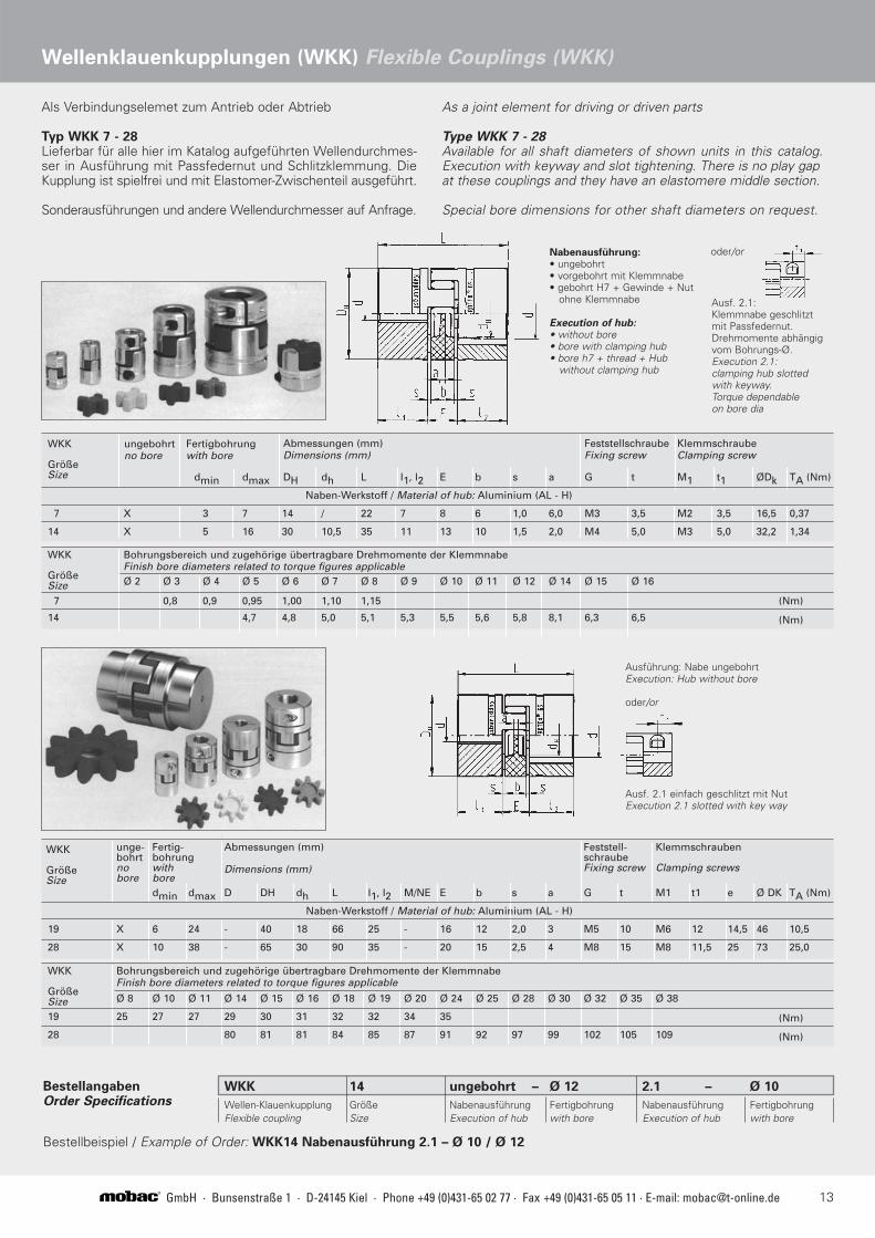
Als Verbindungselemet zum Antrieb oder Abtrieb
Typ WKK 7 - 28Lieferbar für alle hier im Katalog aufgeführten Wellendurchmes-ser in Ausführung mit Passfedernut und Schlitzklemmung. DieKupplung ist spielfrei und mit Elastomer-Zwischenteil ausgeführt.
Sonderausführungen und andere Wellendurchmesser auf Anfrage.
WKK
GrößeSize
Fertigbohrungwith bore
ungebohrtno bore
Abmessungen (mm)Dimensions (mm)
FeststellschraubeFixing screw
KlemmschraubeClamping screw
dmin dmax DH dh L l1, l2 E b s a G t M1 t1 ØDk TA (Nm)
Naben-Werkstoff / Material of hub: Aluminium (AL - H)
7 X 3 7 14 / 22 7 8 6 1,0 6,0 M3 3,5 M2 3,5 16,5 0,37
14 X 5 16 30 10,5 35 11 13 10 1,5 2,0 M4 5,0 M3 5,0 32,2 1,34
WKK
GrößeSize
Bohrungsbereich und zugehörige übertragbare Drehmomente der Klemmnabe Finish bore diameters related to torque figures applicableØ 2 Ø 3 Ø 4 Ø 5 Ø 6 Ø 7 Ø 8 Ø 9 Ø 10 Ø 11 Ø 12 Ø 14 Ø 15 Ø 16
(Nm)
(Nm)
7 0,8 0,9 0,95 1,00 1,10 1,15
14 4,7 4,8 5,0 5,1 5,3 5,5 5,6 5,8 8,1 6,3 6,5
WKK
GrößeSize
unge-bohrtnobore
Fertig-bohrungwithbore
Abmessungen (mm)
Dimensions (mm)
Feststell-schraubeFixing screw
Klemmschrauben
Clamping screws
dmin dmax D DH dh L l1, l2 M/NE E b s a G t M1 t1 e Ø DK TA (Nm)
Naben-Werkstoff / Material of hub: Aluminium (AL - H)
19 X 6 24 - 40 18 66 25 - 16 12 2,0 3 M5 10 M6 12 14,5 46 10,5
28 X 10 38 - 65 30 90 35 - 20 15 2,5 4 M8 15 M8 11,5 25 73 25,0
WKK
GrößeSize
Bohrungsbereich und zugehörige übertragbare Drehmomente der Klemmnabe Finish bore diameters related to torque figures applicable
Ø 8 Ø 10 Ø 11 Ø 14 Ø 15 Ø 16 Ø 18 Ø 19 Ø 20 Ø 24 Ø 25 Ø 28 Ø 30 Ø 32 Ø 35 Ø 38
19 25 27 27 29 30 31 32 32 34 35
28 80 81 81 84 85 87 91 92 97 99 102 105 109
Ausf. 2.1 einfach geschlitzt mit NutExecution 2.1 slotted with key way
Ausf. 2.1: Klemmnabe geschlitzt mit Passfedernut.Drehmomente abhängig vom Bohrungs-Ø.Execution 2.1: clamping hub slotted with keyway.Torque dependable on bore dia
Nabenausführung:• ungebohrt • vorgebohrt mit Klemmnabe• gebohrt H7 + Gewinde + Nut
ohne Klemmnabe
Execution of hub: • without bore• bore with clamping hub• bore h7 + thread + Hub
without clamping hub
Ausführung: Nabe ungebohrtExecution: Hub without bore
oder/or
(Nm)
(Nm)
BestellangabenOrder Specifications
WKK 14 ungebohrt – Ø 12 2.1 – Ø 10
Wellen-Klauenkupplung Größe Nabenausführung Fertigbohrung Nabenausführung FertigbohrungFlexible coupling Size Execution of hub with bore Execution of hub with bore
Bestellbeispiel / Example of Order: WKK14 Nabenausführung 2.1 – Ø 10 / Ø 12
oder/or
As a joint element for driving or driven parts
Type WKK 7 - 28Available for all shaft diameters of shown units in this catalog.Execution with keyway and slot tightening. There is no play gapat these couplings and they have an elastomere middle section.
Special bore dimensions for other shaft diameters on request.
Wellenklauenkupplungen (WKK) Flexible Couplings (WKK)

14 GmbH · Bunsenstraße 1 · D-24145 Kiel · Phone +49 (0)431-65 02 77 · Fax +49 (0)431-65 05 11 · E-mail: [email protected]®
Einfache Wellensicherung
Ausführung in Edelstahl
Verwendbar für ungehärtete Wellen
Wellentoleranz +0,02 / -0,15
FastLock sitzt kraftschlüssig auf derWelle.Entriegeln und abnehmen durchAuseinanderziehen.
Simple Shaft Lock
made of stainless steel
usable for non-hardened shafts
Shaft tolerance +0,02 / -0,15
FastLock is fixed on the shaft by friction contact.Releasing and pulling from the shaft by pressing apart.
C
ØB
ØD
ØA
FastLock
Axiales Schnellspannsystem
für variabel einstellbare Spannkräfte
Nur für gehärtete Wellen
(min. 55 HRC)
Wellentoleranz h6 - h8
Axial Fast Action Clamping
System for variable adjustment
of tensioning forces
For hardened shafts only
(min. 55 HRC)
Shaft tolerance h6 - h8
Spannradtensioning wheel
Sperrringlocking ring
lock sperren
Welle /shaft
releaseentspannen
Spannen
Spannrad 2 - 3 Umdrehungen vordrehen.Vor dem Aufschieben auf die Welle Sperrringund Spannrad auseinanderdrücken (s. Skizze).Spannkonus gegen Rolle schieben.Gewünschte Spannkraft durch Drehung desSpannrades erzeugen.
Lösen
Durch Rückdrehung des SpannradesSpannkraft reduzieren.Sperrring und Spannrad auseinanderdrückenund Spannkonus von der Welle ziehen.
Tensioning
Turn the tensioning wheel forwards by approx. 2 to 3 rotations.Press locking ring and tensioning wheel apartbefore sliding onto shaft (see scetch).Push the clamping pintle up against the roll.Set the desired tension by turning thetensioning wheel.
Releasing
Reduce the clamping pressure by turning thetensioning wheel in the opposite direction.Press locking ring and tensioning wheelapart and pull the clamping pintle off theshaft.
Wellensicherungen Shaft Lockings
Easylock - Typ EL II / EL III - Type EL II / EL III
C
ØA
ØD
ØB
Typenübersicht Types
ØDØAØBC
10222446
FL 1015283545
FL 1516283545
FL 1620374145
FL 2022374145
FL 2225374145
FL 2530515445
FL 3032585748
FL 3235585848
FL 3536585848
FL 3640606448
FL 4045707048
FL 4550707048
FL 5055757548
FL 5556757548
FL 56

15GmbH · Bunsenstraße 1 · D-24145 Kiel · Phone +49 (0)431-65 02 77 · Fax +49 (0)431-65 05 11 · E-mail: [email protected]®
Wellensicherungen Shaft Lockings
EL-10 bis/to EL-22 EL-25 bis/to EL-40
Festkonus/Fixed pintle (F)
a ke
Ød
Øc
Øb Øl
Øm
h
α
nmax.
Øb
Øf
gØ
d Øl
Øm
ae
kh
nmax.
α Øh
Øg
af SW
Øb
Ød α
SpannmodulTensioning Unit
(S)
KonusmodulPintle point(K)
KonusmodulPintle point(K)
SpannmodulTensioning Unit
(S)
Spannkonus/Clamping pintle S + K
EL III
EL III
EL III
EL III
EL III
EL II
EL II
EL III
Ød h6-h8
Ød h6-h8
EL II
EL II
EL II
EL II
EL II
EL II
EL II
EL II

Drahtabläufe und AufwicklerWire Payoffs and Take Ups
mobac-Produkte Products by mobac
Magnetpulver-Bremsen und -KupplungenMagnetic Particle Brakes andClutches
Magnetische VerschließkupplungenMagnetic Capping Clutches
MagnetscheibenkupplungenMagnetic Disc Couplings
Stromerregte HysteresebremsenCurrent Controlled Hysteresis Brakes
Permanentmagneterregte Hysteresebremsen und -kupplungenPermanent Magnetic HysteresisBrakes and Couplings
REPUBLICA ARGENTlNA
TME Tecnologia,Máquinas y EquiposMigueletes 2050 8° D(C1428ASF) Buenos AiresTel. +54 11 4786 9296Fax +54 11 4786 [email protected]
AUSTRALIA
Machinery Forum VIC PTY Ltd.782 Heidelberg RoadFairfield Vic 3078Tel. +61 3 9497 3633Fax +61 3 9497 [email protected]
Machinery Forum NSW PTY Ltd.33 Brodie StreetRydalmere NSW 1701Tel. +61 2 9638 1566Fax +61 2 9638 [email protected]
BRASIL
Intertec Equipamentos Ltda.Rua Da Paz, 134404713-001 São PauloTel. +55 11 5183 2444Fax +55 11 5181 [email protected]
CESKÁ REPUBLICA
Miloslav SvobodaU-Svetle 2062/27B59401 · Velke MeziriciTel. +420 566 522 097 Fax +420 566 544 [email protected]
ESPANA
Electrorrec S.A.C/ dels Pous, 808740 Sant Andreu de la Barca · BarcelonaTel. +34 936 829 611 Fax +34 936 820 [email protected]
ОЯPermanent K&MОЯ, 125424 оскваWolokolamskoje SchausseOffice 517Tel. +7 495 780 34 29Fax +7 495 490 63 [email protected]
MÉXICO
Interequip S.A. DE C.V.Priv. de Horacio 22-50111510 Mexico D.F.Tel. +52 55 5281 4285Fax +52 55 5281 [email protected]
NEDERLAND
IngenieursbureauWendrich & Co.Deldener Straat 1267550 Ab HengeloTel. +31 74 242 2205Fax +31 74 243 [email protected]
POLSKA
Consultex Sp. z.o.oBiuro Doratztwa Techniczno - Handlowegoul. Henryka Rodakowskiego 4/171 - 345 SzczecinTel. +48 91 486 16 18Fax +48 91 486 16 [email protected]
SCANDINAVIA
AB Eric FalkhammarTjärhovsgatan 14102 62 StockholmTel. +46 8 6445 555Fax +46 8 6428 [email protected]
SCHWEIZ/FRANCE
Cabeltec S.A.Av. de la Gottaz 361110 MorgesTel. +41 21 803 09 51Fax +41 21 801 02 [email protected]
REPUBLIC OF SOUTH AFRICA
Macotech Services (PTY) Ltd.Benrose, 2011Johannesburg R.S.A.Tel. +27 11 618 2390Fax +27 11 614 [email protected]
UNITED KINGDOM/EIRE
Techna International Ltd.No. 1, Metro Centre Dwight RoadWatford WD 18 9HGTel. +44 1923 222 227Fax +44 1932 219 [email protected]
Vertretungen / Agents
02/2
010
GmbH · Bunsenstraße 1 · D-24145 Kiel · Phone +49 (0)431-65 02 77 · Fax +49 (0)431-65 05 11 · E-mail: [email protected]®