Embed Size (px)
Citation preview
Stress Engineering of Multi-pass Welds of StructuralSteel to Enhance Structural Integrity
Supriyo Ganguly, Jibrin Sule, and Mustapha Y. Yakubu
(Submitted November 1, 2015; in revised form February 26, 2016; published online May 26, 2016)
In multi-pass welding, the weld metal and the associated heat-affected zone are subjected to repeatedthermal cycling from successive deposition of filler metals. The thermal straining results into multi-modedeformation of the weld metal which causes a variably distributed residual stress field through the thicknessand across the weld of a multi-pass weldment. In addition to this, the as-welded fusion zone microstructureshows dendritic formation of grains and segregation of alloying element. This may result in formation ofmicro-corrosion cells and the problem would aggravate in case of highly alloyed materials. Localmechanical tensioning is an effective way of elimination of the weld tensile residual stress. It has been shownthat application of cold rolling is capable not only of removing the residual stress, but depending on itsmagnitude it may also form beneficial compressive stress state. Multi-pass structural steel welds used asstructural alloy in general engineering and structural applications. Such alloys are subjected to severe in-service degradation mechanisms e.g., corrosion and stress corrosion cracking. Welds and the locked-inresidual stress in the welded area often initiate the defect which finally results in failure. In the presentstudy, a multi-pass structural steel weld metal was first subjected to post-weld cold rolling which wasfollowed by controlled heating by a fiber laser. Cold straining resulted in redistribution of the internal stressthrough the thickness and controlled laser processing helps in reforming of the grain structure. However,even with controlled laser, processing the residual stress is reinstated. Therefore, a strategy has beenadopted to roll the metal post-laser processing so as to obtain a complete stress-free and recrystallizedmicrostructure.
Keywords Laser processing, mechanical properties, microstruc-ture, multi-pass welds, residual stress, rolling, steel
1. Introduction
Steels (especially S275 steels) are a very popular low carbonsteel grade suitable for numerous general engineering andstructural applications. In these applications, it is essential toform strong joints that allow transfer of load between thedifferent steel components. In most cases, welding is generallythe most common method of joining. The welding methodreduced the corrosion problems often associated with fasteners.This process (welding) create most robust joint to theapplication.
The most common and widely used welding processes arethose which employ fusion. Fusion arc welding process relies
on intense local heating at a joint where a certain amount of theparent metal is melted and fused with additional metal from thefiller wire. Fusion arc welding is extensively used in a numberof construction industries, offshore structures, and otherstructural applications. The main benefits of fusion welding,as joining processes, are creation of robust joint, flexibility interms of setting up the equipment, and low fabrication costs.Disadvantage of this process is that the mechanical propertiesof the structural alloy are been alter as result of welding. Thisprocess also causes distortion and residual stresses in thewelded structure.
The distribution of residual stress in the weld is generallytensile in the longitudinal (along-weld) direction close to theweld line, and further away from the weld center line,compressive longitudinal residual stresses exist balancing thosein the weld zone (Ref 1). The presence of tensile residualstresses has been reported to accelerate stress corrosioncracking and fatigue crack growth rates (Ref 2-5), which aredetrimental to the integrity and the service behavior of thewelded joint.
A number of methods have been used to mitigate the effectsof residual stress in welding. These include post-weld heattreatment (Ref 6), shot peening, modification of the structuralconfigurations, and the implementation of thermal tensioningtechniques (Ref 7, 8). It has also been reported that applicationof cold rolling is capable not only of removing the residualstress but depending on its magnitude it may also formbeneficial compressive stress state (Ref 9-13).
In addition to a complex distribution of residual stress state,multi-pass welds also remelt the existing dendritic grainstructure, resulting in aggression of segregation of alloyingelements. Dendritic grain structure is weaker and segregation of
This article is an invited submission to JMEP selected frompresentations at the Symposium ‘‘Joining Technologies,’’ belongingto the Topic ‘‘Joining and Interfaces’’ at the European Congress andExhibition on Advanced Materials and Processes (EUROMAT 2015),held September 20–24, 2015, in Warsaw, Poland, and has beenexpanded from the original presentation.
Supriyo Ganguly and Jibrin Sule, Cranfield - Welding Engineeringand Laser Processing Centre, Cranfield University, MK43 0ALBedford, UK, Northern Ireland; and Mustapha Y. Yakubu, NationalEngineering and Technical Company Limited (NETCO), HeritageCourt 146B Ligali Ayorinde Street, Victoria Island, Lagos, Nigeria.Contact e-mail: [email protected].
JMEPEG (2016) 25:3238–3244 �The Author(s). This article is published with open access at Springerlink.comDOI: 10.1007/s11665-016-2096-2 1059-9495/$19.00
3238—Volume 25(8) August 2016 Journal of Materials Engineering and Performance
alloying elements would result in formation of corrosionmicrocells as well as reduction in overall corrosion resistancedue to localized depletion of alloying elements. Modification ofthe material�s microstructure by heat treatment can have adramatic effect on hardness and fracture toughness in both thefusion region and the heat-affected zone (HAZ), whichconsequently affects fatigue properties greatly.
Our previous work (Ref 14) shows very minimal grainsrefinement and reinstated as-welded residual stress state profilewhen post-weld cold rolling followed by laser processing wasapplied to the sample. Following this observation, differentmethods were used which is the main objective of thisinvestigation.
The aim of this research is to apply this novel method ofcold rolling two times, before and after laser processing tomodify the microstructures, mechanical properties, and residualstress state of multi-pass welds of structural steel.
2. Experiment
2.1 Material
In this study, the material used was S275JR structural steelplate (12 mm thick), and the filler wire used is Union MoNi(1.0 mm diameter). The chemical compositions (in weightpercent) of the S275JR structural steel are 0.11 C, 0.23 Si, 1.08Mn, 0.013 P, 0.02 Ni, 0.03 Al, 0.02 Cr, 0.03 Cu, 0.005 S, andothers which include little quantity of Mo, Nb, Ti, and V. Thefiller wire used has the following chemical compositions (inweight percent): 0.12 C, 0.4-0.8 Si, 1.3-1.9 Mn, 0.015 P, 0.8-1.3 Ni, 0.25-0.65 Mo, Al, 0.15 Cr, 0.3 Cu, 0.018 S, and others.The shielding gas used was 92% Ar and 8% CO2 at flow rate of30 l min�1. Figure 1 shows the welding set-up and the bevelwas filled with four (4) welding passes.
2.2 Experimental Method
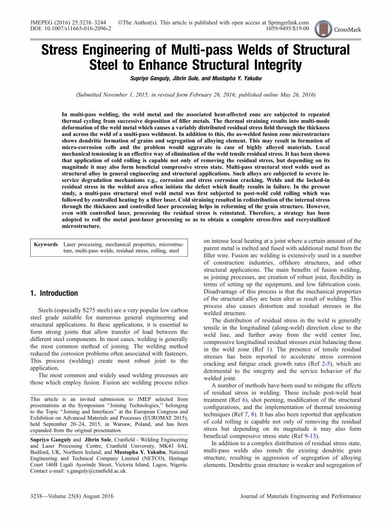
In this research the samples were processed in three stagesafter welding as given below. Metallography, mechanical
properties, and residual stress measurement were carried outafter each stage as shown in the flow chart in Fig. 2.
2.2.1 Welding. The welding was carried out using Tan-dem Gas Metal Arc Welding process. Welding parameters usedare shown in Table 1.
The heat input was calculated using Eq 1.
Heat input ¼ current x voltage x efficiencyð Þ= Travel speedð ÞðEq 1Þ
An efficiency factor of 80% was used (Ref 4).Note that, the instantaneous current and voltage were
recorded using a Scopecorder 750. The values were averagedfor a certain period of stabilized welding, and these are used forcomputing the heat input.
2.2.2 Rolling Device. Post-weld cold rolling was carriedout using the in-house rolling machine. This rolling device iscapable of rolling with a constant force. The principle ofoperation of this machine was explained elsewhere (Ref 14).This roller was made from hardened BS 4659 BH13 tool steel.It has an effective width of 30 mm and the diameter of100 mm. The rolling load of 150 kN with a constant travelspeed of 700 mm min�1 was applied to welded sample.
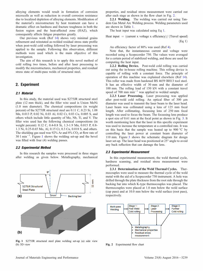
2.2.3 Laser Processing. Laser processing was appliedafter post-weld cold rolling. An optical fiber of 300 lmdiameter was used to transmit the laser beam to the laser head.Laser beam was collimated using a lens of 125 mm focallength. After collimating, focussing lens of 250 mm focallength was used to focus the beam. The focussing lens producea spot size of 0.61 mm at the focal point as shown in Fig. 3. Itworth mentioning here that the laser in this specific experimentwas used to increase the temperature at a controlled rate. It wason this basis that the sample was heated up to 900 �C bycontrolling the laser power at constant beam diameter of110 mm. Figure 3 shows the schematic diagram for designlaser set-up. The laser head was positioned at 25� angle to avoidany back reflection that can damage the lens.
2.3 Experimental Measurement
In this experimental measurement, the weld thermal cycle,hardness scanning, and residual stress measurement wereperformed.
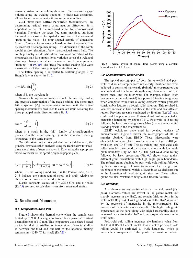
2.3.1 Determination of the Weld Thermal Cycles. Ther-mocouples were used to measure the thermal cycle of the weldmetal with the aid of a Scopecorder 750 instrument. A hole wasdrilled through the plate thickness from the root side through thebacking bar into which K-type thermocouples was placed. Thethermocouples were placed at 1.0 mm below the weld surface(cap pass) and at 10.0 mm below the weld surface (root pass),respectively.
Fig. 1 S275JR structural steel plate welding set-up (a) side view(b) 3D view Fig. 2 Experimental flow chart
Journal of Materials Engineering and Performance Volume 25(8) August 2016—3239
2.3.2 Hardness Measurement. Welded samples wereprepared according to standard metallography procedures formicrostructural observations and micro hardness tests. Formicrohardness testing, 0.5 kg load and 10 s dwell time wereapplied. Hardness scan was carried out across and along theweld metal at an interval of 1.0 mm within successive points.
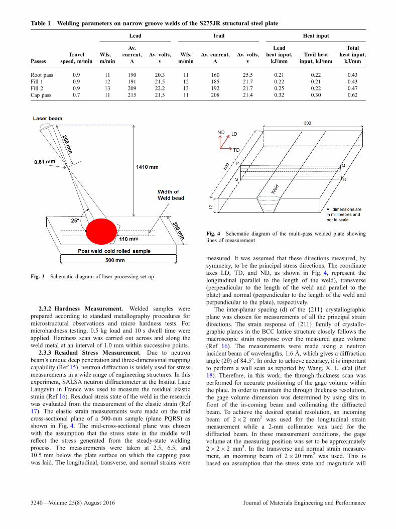
2.3.3 Residual Stress Measurement. Due to neutronbeam�s unique deep penetration and three-dimensional mappingcapability (Ref 15), neutron diffraction is widely used for stressmeasurements in a wide range of engineering structures. In thisexperiment, SALSA neutron diffractometer at the Institut LaueLangevin in France was used to measure the residual elasticstrain (Ref 16). Residual stress state of the weld in the researchwas evaluated from the measurement of the elastic strain (Ref17). The elastic strain measurements were made on the midcross-sectional plane of a 500-mm sample (plane PQRS) asshown in Fig. 4. The mid-cross-sectional plane was chosenwith the assumption that the stress state in the middle willreflect the stress generated from the steady-state weldingprocess. The measurements were taken at 2.5, 6.5, and10.5 mm below the plate surface on which the capping passwas laid. The longitudinal, transverse, and normal strains were
measured. It was assumed that these directions measured, bysymmetry, to be the principal stress directions. The coordinateaxes LD, TD, and ND, as shown in Fig. 4, represent thelongitudinal (parallel to the length of the weld), transverse(perpendicular to the length of the weld and parallel to theplate) and normal (perpendicular to the length of the weld andperpendicular to the plate), respectively.
The inter-planar spacing (d) of the {211} crystallographicplane was chosen for measurements of all the principal straindirections. The strain response of {211} family of crystallo-graphic planes in the BCC lattice structure closely follows themacroscopic strain response over the measured gage volume(Ref 16). The measurements were made using a neutronincident beam of wavelengths, 1.6 A, which gives a diffractionangle (2h) of 84.5�. In order to achieve accuracy, it is importantto perform a wall scan as reported by Wang, X. L. et�al (Ref18). Therefore, in this work, the through-thickness scan wasperformed for accurate positioning of the gage volume withinthe plate. In order to maintain the through thickness resolution,the gage volume dimension was determined by using slits infront of the in-coming beam and collimating the diffractedbeam. To achieve the desired spatial resolution, an incomingbeam of 29 2 mm2 was used for the longitudinal strainmeasurement while a 2-mm collimator was used for thediffracted beam. In these measurement conditions, the gagevolume at the measuring position was set to be approximately29 29 2 mm3. In the transverse and normal strain measure-ment, an incoming beam of 29 20 mm2 was used. This isbased on assumption that the stress state and magnitude will
Table 1 Welding parameters on narrow groove welds of the S275JR structural steel plate
PassesTravel
speed, m/min
Lead Trail Heat input
Wfs,m/min
Av.current,
AAv. volts,
vWfs,m/min
Av. current,A
Av. volts,v
Leadheat input,kJ/mm
Trail heatinput, kJ/mm
Totalheat input,kJ/mm
Root pass 0.9 11 190 20.3 11 160 25.5 0.21 0.22 0.43Fill 1 0.9 12 191 21.5 12 185 21.7 0.22 0.21 0.43Fill 2 0.9 13 209 22.2 13 192 21.7 0.25 0.22 0.47Cap pass 0.7 11 215 21.5 11 208 21.4 0.32 0.30 0.62
Fig. 3 Schematic diagram of laser processing set-up
Fig. 4 Schematic diagram of the multi-pass welded plate showinglines of measurement
3240—Volume 25(8) August 2016 Journal of Materials Engineering and Performance
remain constant in the welding direction. The increase in gagevolume along the welding direction, in these two directions,allows faster measurement with more grain sampling.
2.3.4 Stress-Free Lattice Parameter Measurement. Indetermining residual stress using neutron diffraction, it isimportant to correct the measured strain for compositionalvariation. Therefore, the stress-free comb machined out fromthe weld is measured for spatial correction of the measuredstrain in the plate. The comb-shaped sample of dimension6 mm9 6 mm9 5 mm was machined out from the parent plateby electrical discharge machining. This dimension of the combwould ensure relaxation of any macroresidual stress field. Thecomb geometry would also allow positional correction of themeasured strain for compositional variation across the weld andalso any changes in lattice parameter due to intergranularstraining (Ref 19, 20). The stress-free lattice spacing d0ð Þ weremeasured in all the three principal strain directions.
The lattice spacing d is related to scattering angle h byBragg�s law as shown in Eq 2.
k ¼ 2dhkl sinh2
� �; ðEq 2Þ
where k is the wavelengthGaussian fitting routine was used to fit the intensity profile
and precise determination of the peak position. The stress-freelattice spacing d0ð Þ measurement combined with the latticespacing measurements was used to calculate strain eð Þ along thethree principal strain direction using Eq 3.
ehkl ¼dhkld0hkl
� 1
� �; ðEq 3Þ
where e is strain in the {hkl} family of crystallographicplanes, d is the lattice spacing, d0 is the strain-free spacing(measured in the same plane).
Once the strain in the principal direction are determined, theprincipal stresses are then analyzed using the Hooke�s law for three-dimensional state of stress as shown in Eq 4, using the appropriateelastic constants for the specific crystallographic plane.
rii ¼E
1þ tð Þ eii þt
1� 2tð Þ e11 þ e22 þ e33ð Þ� �
; ðEq 4Þ
where E is the Young�s modulus, t is the Poisson ratio, i = 1,2, 3 indicate the component of stress and strain relative tochosen to the principal strain directions.
Elastic constants values of E = 225.5 GPa and t = 0.28(Ref 5) are used to calculate stress from measured strains.
3. Results and Discussion
3.1 Temperature–Time Plot
Figure 5 shows the thermal cycle when the sample washeated up to 900 �C using a controlled laser power at constantbeam diameter of 110 mm. This temperature was selected basedon the fact that recrystallization temperature of structural alloyis between one-third and one-half of the absolute meltingtemperature (1540 �C for steel) (Ref 21).
3.2 Microstructural Observations
The optical micrographs of both the as-welded and post-weld cold rolled samples were not clearly identified but werebelieved to consist of martensitic (bainitic) microstructures dueto enriched solid solution strengthening element in both theparent metal and the filler wire. For example, silicon (highpercentage in the weld metal) is a powerful ferrite strengthenerwhen compared with other alloying elements which promotesconsiderable hardness through solid solution. This resulted inlocalized increase in hardenability in the weld and heat-affectedregion. Previous research conducted by Ibrahim (Ref 22) alsoconfirmed this phenomenon. Post-weld cold rolling resulted inincreasing hardening by about 50 HV. Post-weld cold rollingfollowed by laser processing shows M-A (martensite-austenite)islands present in the microstructure.
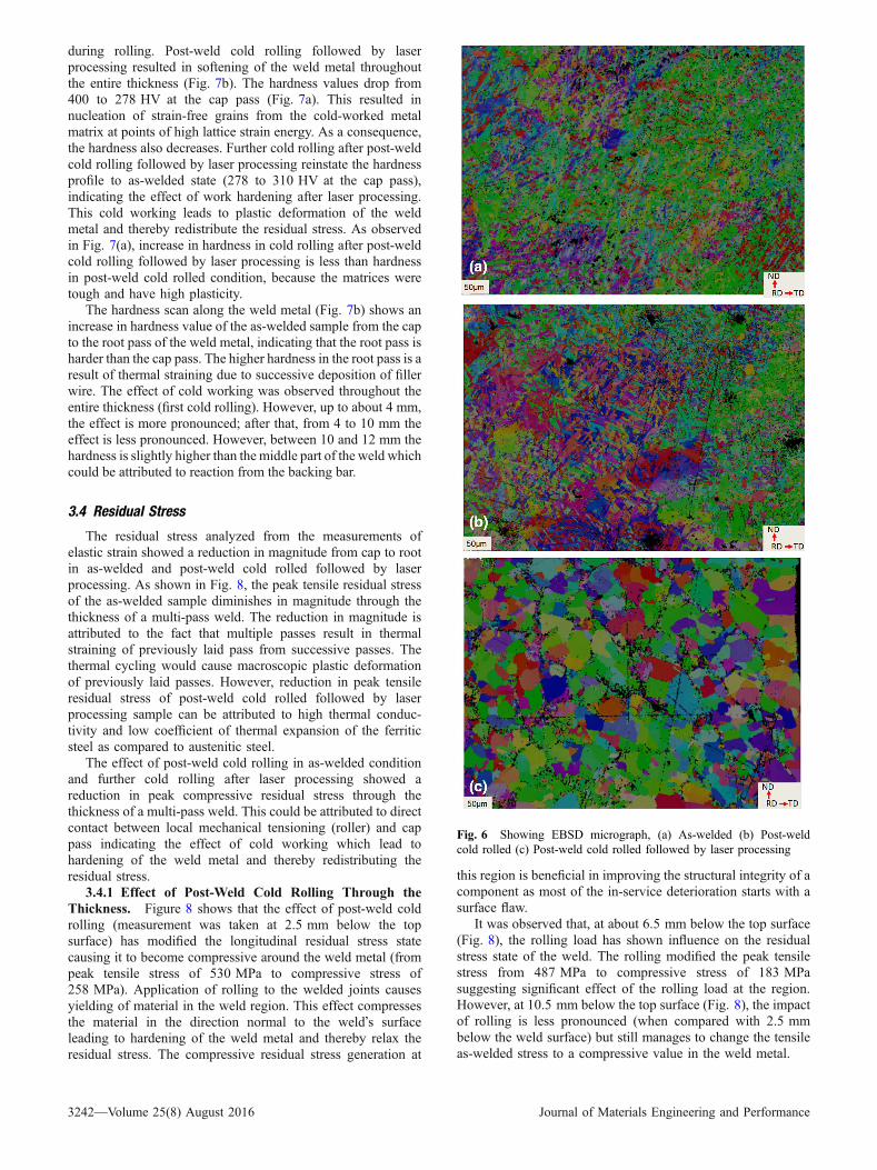
EBSD techniques were used for detailed analysis ofmicrostructure. Figure 6 shows the micrographs of all thesamples obtained from EBSD. These micrographs wereobtained from data collected over an area of 538 lm9 401 lmwith step size 0.437 lm. The as-welded and post-weld coldrolled samples have dendritic grains structure with low anglegrain boundary (Fig. 6a and b). The post-weld cold rollingfollowed by laser processing (Fig. 6c) shows clear grains,different grain orientations with high angle grain boundaries.The refined grains obtained by post-weld cold rolling followedby laser processing is known to increase the strength andtoughness of the material which is lower in as-welded state dueto the formation of dendritic grain structure. These refinedgrains are also resistant to fatigue and fracture failures.
3.3 Hardness
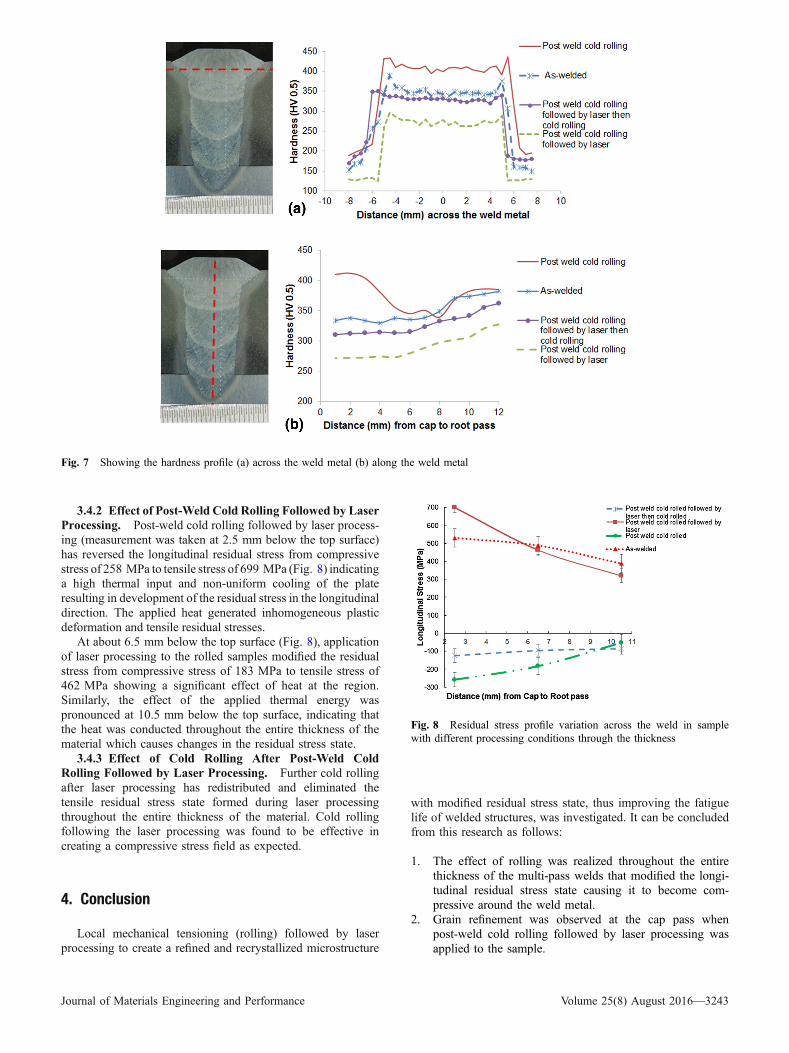
A hardness scan was performed across the weld metal (cappass). Hardness values are lowest in the parent metal, butsharply increase in the HAZ, and remain fairly uniform in theweld metal (Fig. 7a). This high hardness at the HAZ is causedby the presence of martensite in the microstructure. Thepresence of martensite was as a result of the high cooling rateexperienced at the zone along with high hardenability due toincreased grain size in the HAZ and the alloying elements in theweld metal.
Post-weld cold rolling increases the hardness value from341 to 400 HV at the weld metal. This effect of post-weld coldrolling could be attributed to work hardening which isinevitable consequence of the plastic deformation induced
Fig. 5 Thermal cycles of control laser power using a constantbeam diameter of 110 mm
Journal of Materials Engineering and Performance Volume 25(8) August 2016—3241
during rolling. Post-weld cold rolling followed by laserprocessing resulted in softening of the weld metal throughoutthe entire thickness (Fig. 7b). The hardness values drop from400 to 278 HV at the cap pass (Fig. 7a). This resulted innucleation of strain-free grains from the cold-worked metalmatrix at points of high lattice strain energy. As a consequence,the hardness also decreases. Further cold rolling after post-weldcold rolling followed by laser processing reinstate the hardnessprofile to as-welded state (278 to 310 HV at the cap pass),indicating the effect of work hardening after laser processing.This cold working leads to plastic deformation of the weldmetal and thereby redistribute the residual stress. As observedin Fig. 7(a), increase in hardness in cold rolling after post-weldcold rolling followed by laser processing is less than hardnessin post-weld cold rolled condition, because the matrices weretough and have high plasticity.
The hardness scan along the weld metal (Fig. 7b) shows anincrease in hardness value of the as-welded sample from the capto the root pass of the weld metal, indicating that the root pass isharder than the cap pass. The higher hardness in the root pass is aresult of thermal straining due to successive deposition of fillerwire. The effect of cold working was observed throughout theentire thickness (first cold rolling). However, up to about 4 mm,the effect is more pronounced; after that, from 4 to 10 mm theeffect is less pronounced. However, between 10 and 12 mm thehardness is slightly higher than the middle part of the weld whichcould be attributed to reaction from the backing bar.
3.4 Residual Stress
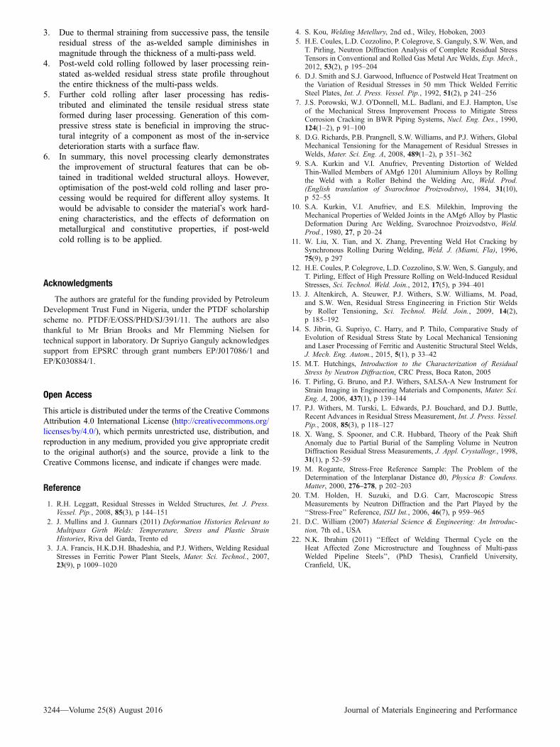
The residual stress analyzed from the measurements ofelastic strain showed a reduction in magnitude from cap to rootin as-welded and post-weld cold rolled followed by laserprocessing. As shown in Fig. 8, the peak tensile residual stressof the as-welded sample diminishes in magnitude through thethickness of a multi-pass weld. The reduction in magnitude isattributed to the fact that multiple passes result in thermalstraining of previously laid pass from successive passes. Thethermal cycling would cause macroscopic plastic deformationof previously laid passes. However, reduction in peak tensileresidual stress of post-weld cold rolled followed by laserprocessing sample can be attributed to high thermal conduc-tivity and low coefficient of thermal expansion of the ferriticsteel as compared to austenitic steel.
The effect of post-weld cold rolling in as-welded conditionand further cold rolling after laser processing showed areduction in peak compressive residual stress through thethickness of a multi-pass weld. This could be attributed to directcontact between local mechanical tensioning (roller) and cappass indicating the effect of cold working which lead tohardening of the weld metal and thereby redistributing theresidual stress.
3.4.1 Effect of Post-Weld Cold Rolling Through theThickness. Figure 8 shows that the effect of post-weld coldrolling (measurement was taken at 2.5 mm below the topsurface) has modified the longitudinal residual stress statecausing it to become compressive around the weld metal (frompeak tensile stress of 530 MPa to compressive stress of258 MPa). Application of rolling to the welded joints causesyielding of material in the weld region. This effect compressesthe material in the direction normal to the weld�s surfaceleading to hardening of the weld metal and thereby relax theresidual stress. The compressive residual stress generation at
this region is beneficial in improving the structural integrity of acomponent as most of the in-service deterioration starts with asurface flaw.
It was observed that, at about 6.5 mm below the top surface(Fig. 8), the rolling load has shown influence on the residualstress state of the weld. The rolling modified the peak tensilestress from 487 MPa to compressive stress of 183 MPasuggesting significant effect of the rolling load at the region.However, at 10.5 mm below the top surface (Fig. 8), the impactof rolling is less pronounced (when compared with 2.5 mmbelow the weld surface) but still manages to change the tensileas-welded stress to a compressive value in the weld metal.
Fig. 6 Showing EBSD micrograph, (a) As-welded (b) Post-weldcold rolled (c) Post-weld cold rolled followed by laser processing
3242—Volume 25(8) August 2016 Journal of Materials Engineering and Performance
3.4.2 Effect of Post-Weld Cold Rolling Followed by LaserProcessing. Post-weld cold rolling followed by laser process-ing (measurement was taken at 2.5 mm below the top surface)has reversed the longitudinal residual stress from compressivestress of 258 MPa to tensile stress of 699 MPa (Fig. 8) indicatinga high thermal input and non-uniform cooling of the plateresulting in development of the residual stress in the longitudinaldirection. The applied heat generated inhomogeneous plasticdeformation and tensile residual stresses.
At about 6.5 mm below the top surface (Fig. 8), applicationof laser processing to the rolled samples modified the residualstress from compressive stress of 183 MPa to tensile stress of462 MPa showing a significant effect of heat at the region.Similarly, the effect of the applied thermal energy waspronounced at 10.5 mm below the top surface, indicating thatthe heat was conducted throughout the entire thickness of thematerial which causes changes in the residual stress state.
3.4.3 Effect of Cold Rolling After Post-Weld ColdRolling Followed by Laser Processing. Further cold rollingafter laser processing has redistributed and eliminated thetensile residual stress state formed during laser processingthroughout the entire thickness of the material. Cold rollingfollowing the laser processing was found to be effective increating a compressive stress field as expected.
4. Conclusion
Local mechanical tensioning (rolling) followed by laserprocessing to create a refined and recrystallized microstructure
with modified residual stress state, thus improving the fatiguelife of welded structures, was investigated. It can be concludedfrom this research as follows:
1. The effect of rolling was realized throughout the entirethickness of the multi-pass welds that modified the longi-tudinal residual stress state causing it to become com-pressive around the weld metal.
2. Grain refinement was observed at the cap pass whenpost-weld cold rolling followed by laser processing wasapplied to the sample.
Fig. 7 Showing the hardness profile (a) across the weld metal (b) along the weld metal
Fig. 8 Residual stress profile variation across the weld in samplewith different processing conditions through the thickness
Journal of Materials Engineering and Performance Volume 25(8) August 2016—3243
3. Due to thermal straining from successive pass, the tensileresidual stress of the as-welded sample diminishes inmagnitude through the thickness of a multi-pass weld.
4. Post-weld cold rolling followed by laser processing rein-stated as-welded residual stress state profile throughoutthe entire thickness of the multi-pass welds.
5. Further cold rolling after laser processing has redis-tributed and eliminated the tensile residual stress stateformed during laser processing. Generation of this com-pressive stress state is beneficial in improving the struc-tural integrity of a component as most of the in-servicedeterioration starts with a surface flaw.
6. In summary, this novel processing clearly demonstratesthe improvement of structural features that can be ob-tained in traditional welded structural alloys. However,optimisation of the post-weld cold rolling and laser pro-cessing would be required for different alloy systems. Itwould be advisable to consider the material�s work hard-ening characteristics, and the effects of deformation onmetallurgical and constitutive properties, if post-weldcold rolling is to be applied.
Acknowledgments
The authors are grateful for the funding provided by PetroleumDevelopment Trust Fund in Nigeria, under the PTDF scholarshipscheme no. PTDF/E/OSS/PHD/SJ/391/11. The authors are alsothankful to Mr Brian Brooks and Mr Flemming Nielsen fortechnical support in laboratory. Dr Supriyo Ganguly acknowledgessupport from EPSRC through grant numbers EP/J017086/1 andEP/K030884/1.
Open Access
This article is distributed under the terms of the Creative CommonsAttribution 4.0 International License (http://creativecommons.org/licenses/by/4.0/), which permits unrestricted use, distribution, andreproduction in any medium, provided you give appropriate creditto the original author(s) and the source, provide a link to theCreative Commons license, and indicate if changes were made.
Reference
1. R.H. Leggatt, Residual Stresses in Welded Structures, Int. J. Press.Vessel. Pip., 2008, 85(3), p 144–151
2. J. Mullins and J. Gunnars (2011) Deformation Histories Relevant toMultipass Girth Welds: Temperature, Stress and Plastic StrainHistories, Riva del Garda, Trento ed
3. J.A. Francis, H.K.D.H. Bhadeshia, and P.J. Withers, Welding ResidualStresses in Ferritic Power Plant Steels, Mater. Sci. Technol., 2007,23(9), p 1009–1020
4. S. Kou, Welding Metellury, 2nd ed., Wiley, Hoboken, 20035. H.E. Coules, L.D. Cozzolino, P. Colegrove, S. Ganguly, S.W. Wen, and
T. Pirling, Neutron Diffraction Analysis of Complete Residual StressTensors in Conventional and Rolled Gas Metal Arc Welds, Exp. Mech.,2012, 53(2), p 195–204
6. D.J. Smith and S.J. Garwood, Influence of Postweld Heat Treatment onthe Variation of Residual Stresses in 50 mm Thick Welded FerriticSteel Plates, Int. J. Press. Vessel. Pip., 1992, 51(2), p 241–256
7. J.S. Porowski, W.J. O�Donnell, M.L. Badlani, and E.J. Hampton, Useof the Mechanical Stress Improvement Process to Mitigate StressCorrosion Cracking in BWR Piping Systems, Nucl. Eng. Des., 1990,124(1–2), p 91–100
8. D.G. Richards, P.B. Prangnell, S.W. Williams, and P.J. Withers, GlobalMechanical Tensioning for the Management of Residual Stresses inWelds, Mater. Sci. Eng. A, 2008, 489(1–2), p 351–362
9. S.A. Kurkin and V.I. Anufriev, Preventing Distortion of WeldedThin-Walled Members of AMg6 1201 Aluminium Alloys by Rollingthe Weld with a Roller Behind the Welding Arc, Weld. Prod.(English translation of Svarochnoe Proizvodstvo), 1984, 31(10),p 52–55
10. S.A. Kurkin, V.I. Anufriev, and E.S. Milekhin, Improving theMechanical Properties of Welded Joints in the AMg6 Alloy by PlasticDeformation During Arc Welding, Svarochnoe Proizvodstvo, Weld.Prod., 1980, 27, p 20–24
11. W. Liu, X. Tian, and X. Zhang, Preventing Weld Hot Cracking bySynchronous Rolling During Welding, Weld. J. (Miami, Fla), 1996,75(9), p 297
12. H.E. Coules, P. Colegrove, L.D. Cozzolino, S.W. Wen, S. Ganguly, andT. Pirling, Effect of High Pressure Rolling on Weld-Induced ResidualStresses, Sci. Technol. Weld. Join., 2012, 17(5), p 394–401
13. J. Altenkirch, A. Steuwer, P.J. Withers, S.W. Williams, M. Poad,and S.W. Wen, Residual Stress Engineering in Friction Stir Weldsby Roller Tensioning, Sci. Technol. Weld. Join., 2009, 14(2),p 185–192
14. S. Jibrin, G. Supriyo, C. Harry, and P. Thilo, Comparative Study ofEvolution of Residual Stress State by Local Mechanical Tensioningand Laser Processing of Ferritic and Austenitic Structural Steel Welds,J. Mech. Eng. Autom., 2015, 5(1), p 33–42
15. M.T. Hutchings, Introduction to the Characterization of ResidualStress by Neutron Diffraction, CRC Press, Boca Raton, 2005
16. T. Pirling, G. Bruno, and P.J. Withers, SALSA-A New Instrument forStrain Imaging in Engineering Materials and Components, Mater. Sci.Eng. A, 2006, 437(1), p 139–144
17. P.J. Withers, M. Turski, L. Edwards, P.J. Bouchard, and D.J. Buttle,Recent Advances in Residual Stress Measurement, Int. J. Press. Vessel.Pip., 2008, 85(3), p 118–127
18. X. Wang, S. Spooner, and C.R. Hubbard, Theory of the Peak ShiftAnomaly due to Partial Burial of the Sampling Volume in NeutronDiffraction Residual Stress Measurements, J. Appl. Crystallogr., 1998,31(1), p 52–59
19. M. Rogante, Stress-Free Reference Sample: The Problem of theDetermination of the Interplanar Distance d0, Physica B: Condens.Matter, 2000, 276–278, p 202–203
20. T.M. Holden, H. Suzuki, and D.G. Carr, Macroscopic StressMeasurements by Neutron Diffraction and the Part Played by the‘‘Stress-Free’’ Reference, ISIJ Int., 2006, 46(7), p 959–965
21. D.C. William (2007) Material Science & Engineering: An Introduc-tion, 7th ed., USA
22. N.K. Ibrahim (2011) ‘‘Effect of Welding Thermal Cycle on theHeat Affected Zone Microstructure and Toughness of Multi-passWelded Pipeline Steels’’, (PhD Thesis), Cranfield University,Cranfield, UK,
3244—Volume 25(8) August 2016 Journal of Materials Engineering and Performance