Embed Size (px)
Citation preview
STRESS CORROSION CRACKING IN HIGH
STRENGTH STEEL--OR HYDROGEN
EMBRITTLEMENT?
By I. WEIBULL
Head of Materials Lab., Saab Aircraft Co., Sweden
Abstract--Amongst the problems encountered in the use of high strength steels, thatof delayed failure is one of the most complex. Some observations made at Saab AircraftCompany point to corrosion unde r stress as one possible source of such failures. In thispaper, some corrosion tests under stress in a humidity cabinet with steels of differentcompositions and hardness levels will be described and their results analysed in comparisonwith practical experience. Some experiments were carried out to investigate if the failureswere due to true stress corrosion cracking or to hydrogen embrittlement, induced bycorrosion.
Zusanunenfassung—Unter den Erscheinungen, die man in der Anwendung hochfesterStähle begegnet, ist der spröde Dauerstandbruch einer der meist komplizierten. Beo-bachtungen bei Saab zeigen auf Korrosion unter Spannung als eine der moglichenUrsachen solcher Brüche. In diesem Aufsatz werden einige Korrosionsversuche in einemKlimaschrank mit Stählen verschiedener Zusammensetzung und Wine beschrieben.Die Ergebnisse werden erörtert und mit der praktischen Erfahrung verglichen. EinigeVersuche wurden ausgefiihrt um zu untersuchen, ob die Briiche durch wahre Span-nungsrisskorrosion verursacht wurden oder durch Wasserstoffsprodigkeit als eine Folgeder Korrosion.
Avant-propos—Parmi les phenomenes rencontrés dans l'usage des aciers à haute resistance,la rupture retardée est un des plus compliqués. Observations faites aux laboratoiresde la Saab indiquent la corrosion sous tension comme une des causes possibles de telles
ruptures. L'auteur décrit quelques essais de corrosion dans une chambre d'étuve avecdes aciers de composition et resistance differente. Les résulats sont discutés en comparisonavec l'experience dans la pratique. Quelques essais étaient realises afin de decider siles ruptures étaient produites par la corrosion fissurantc sous tension proprement diteou par la fragilisation par l'hydrogene comme suite à la corrosion.
INTRODUCTION
WITH the exception of spring and ball bearing steels, before 1945 steels were very seldom used for constructional purposes at strength levels above 200,000 psi. There were various reasons for this reluctance but one of the most important ones was certainly that the impact strength of steel was considered to be too low at such strength levels. It was also known
1335]
336 I. WLIBUI L
that the notch sensitivity in fatigue increased markedly with the strength
level.
Two factors have radically changed our approach to strength levels
in steel above 200,000 psi: First, the ever-increasing demand for lower
weight and higher strength in aircraft parts and second, the adv ent of
other competing materials with a high strength to weight ratio, such as
the high strength aluminum-zinc-magnesium alloys and the titanium
alloys. In many of these the impact strength is quite low as is also thenotch fatigue strength. However, with due regard to such circumstances,
these materials function well enough.
Thus, a rapid development began, which would permit an increased
strength in steel without endangering the safety of aircraft. Two lines
of approach were tried:One aimed at developing a steel which, after quenching, could be tem-
pered without any sacrifice in strength at a temperature outside the low
impact strength region characteristic of most steels. A typical product of
this line of approach was the Hy-tuf-steel, introduced by Crucible Steel
Co. of America in 1948. This steel is capable of a minimum tensile strengthof 230,000 psi with a very good ductility. The nominal composition is:
C Mn Si Cr Ni Mo
0.15 1.3 1.5 0.3 1.8 0.4
Still higher strength can be obtained in steels of the same type with
a higher carbon content, such as Super-Hy-tuf, Tricent and others.
Another line of approach was to improve the properties and treatment
of existing steels. In this way it was found possible to use the SAE 4340steel to a considerably higher strength level than anticipated before. This
is now the dominating steel in the USA for high strength steel parts in
aircraft.
SWEDISH EXPERIENCE OF HIGH STRENGTH STEELS
In Sweden, a steel similar to SAE 4340 with the Saab designation steel
1366 was used for a long time for similar applications and at a minimum
strength level of 185,000 psi. The nominal composition of this steel is:
C Mn Si Cr Ni Mo
OE30 OE55 OE25 1.0 3.2 0.25
About ten years ago the first difficulties in the use of this steel v ere
encountered. Cadmium-plated threaded bolts failed under sustained load
in a brittle manner. Extensive investigations showed this to be caused
by hydrogen diffused into the steel during the plating operation. Therefore,
Stress Corrosion Cracking in High Strength Steel 337
for this steel and other high strength steels, cadmium plating was replacedby acid zinc plating and for critical applications all plating was avoidedas far as possible. The time and temperature for baking after theplating operation were also increased.
In this way the troubles caused by hydro2en imbrittlement in platingv‘ere practically eliminated.
a
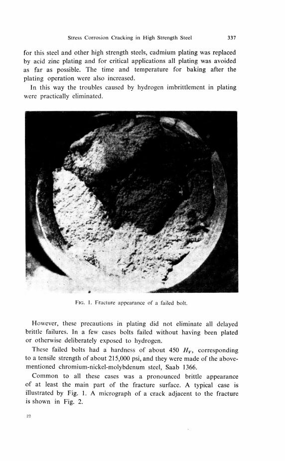
a
Flo. I. Fracture appearance of a failed bolt.
However, these precautions in plating did not eliminate all delayedbrittle failures. In a few cases bolts failed without having been platedor otherwise deliberately exposed to hydrogen.
These failed bolts had a hardness of about 450 H v, correspondingto a tensile strength of about 215,000 psi, and they were made of the above-mentioned chromium-nickel-molybdenum steel, Saab 1366.
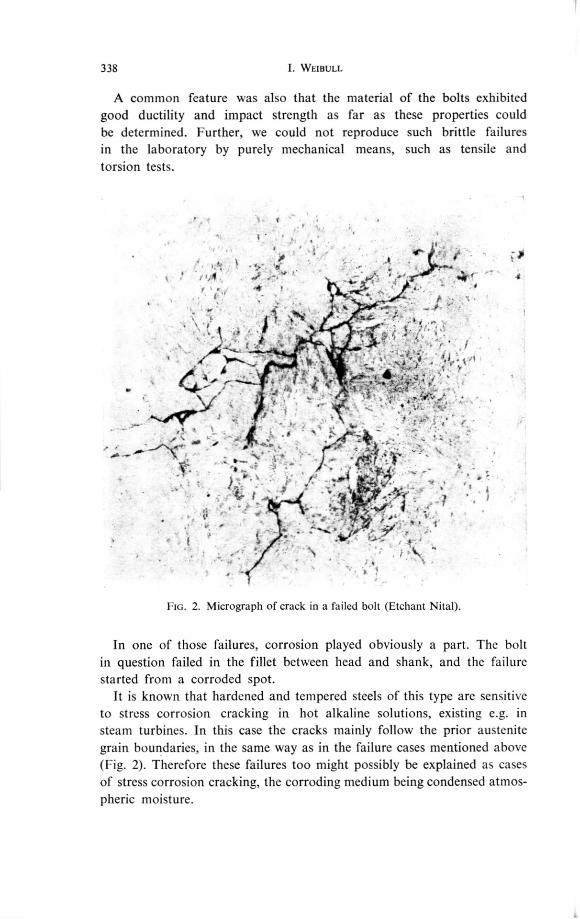
Common to all these cases was a pronounced brittle appearanceof at least the main part of the fracture surface. A typical case isillustrated by Fig. 1. A micrograph of a crack adjacent to the fractureis shown in Fig. 2.
22
338 I. WEIBULL
A common feature was also that the material of the bolts exhibitedgood ductility and impact strength as far as these properties couldbe determined. Further, we could not reproduce such brittle failuresin the laboratory by purely mechanical means, such as tensile andtorsion tests.
Ho. 2. Micrograph of crack in a failed bolt (Etchant Nital).
In one of those failures, corrosion played obviously a part. The boltin question failed in the fillet between head and shank, and the failurestarted from a corroded spot.
It is known that hardened and tempered steels of this type are sensitiveto stress corrosion cracking in hot alkaline solutions, existing e.g. insteam turbines. In this case the cracks mainly follow the prior austenite
grain boundaries, in the same way as in the failure cases mentioned above(Fig. 2). Therefore these failures too might possibly be explained as casesof stress corrosion cracking, the corroding medium being condensed atmos-pheric moisture.
Stress Corrosion Cracking in High Strength Steel 339
CORROSION TESTS UNDER STRESS IN A HUMIDITY CABINET
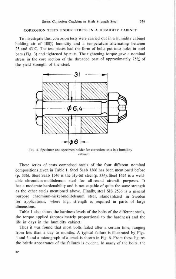
To investigate this, corrosion tests were carried out in a humidity cabinetholding air of 100% humidity and a temperature alternating between
25 and 43`C. The test pieces had the form of bolts put into holes in steel
bars (Fig. 3) and tightened by nuts. The tightening torque gave a nominal
stress in the core section of the threaded part of approximately 75% of
the yield strength of the steel.
31 -
06,14
FIG. 3. Specimen and specimen holder for corrosion tests in a humiditycabinet.
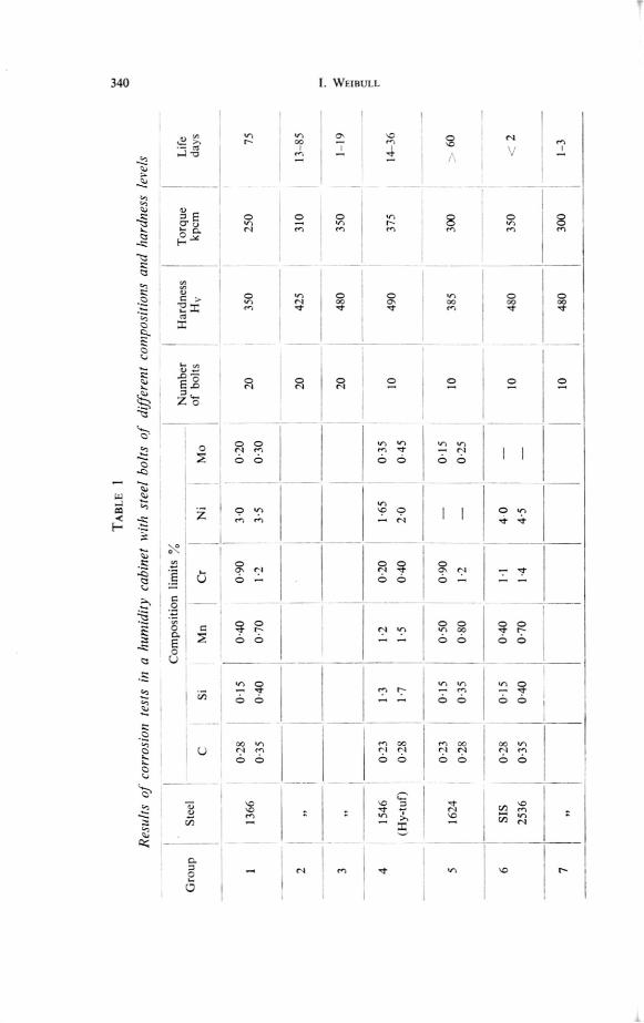
These series of tests comprised steels of thc four different nominal
compositions given in Table 1. Steel Saab 1366 has been mentioned before
(p. 336). Steel Saab 1546 is the Hy-tuf steel (p. 336). Steel 1624 is a weld-able chromium-molibdenum steel for all-round aircraft purposes. It
has a moderate hardenability and is not capable of quite the same strength
as the other steels mentioned abol,e. Finally, steel SIS 2536 is a general
purpose chromium-nickel-molibdenum steel, standardized in Sweden
for applications, where high strength is required in parts of large
dimensions.Table I also shows the hardness levels of the bolts of the different steels,
the torque applied (approximately proportional to the hardness) and the
life in days in the humidity cabinet.
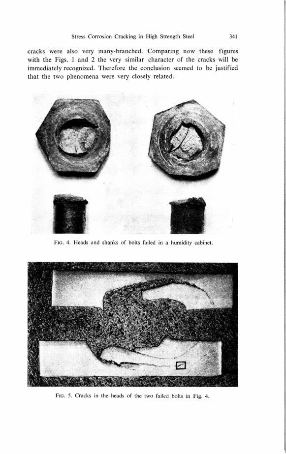
Thus it was found that most bolts failed after a certain time, ranging
from less than a day to months. A typical failure is illustrated by Figs.
4 and 5 and a micrograph of a crack is shown in Fig. 6. From these figures
the brittle appearance of the failures is evident. In many of the bolts, the
22*
TA
BL
E
I
Re
sults
of
corr
osio
n
tests
in
a
hu
mid
ity
cab
ine
t w
ith
ste
el
bo
lts
of
diffe
rent
co
mp
ositio
ns
an
d
hard
ne
ss
levels
Gro
up
Ste
el
Co
mpositio
n
lim
its
MnC
rN
iM
o
Num
ber
of
bo
lts
IH
ard
ness
I-1
vT
orq
ue
kp
cm
Life
da
ys
0.2
80
-15
0.4
00
.90
3.0
0.2
0
1
1366
2
035
02
50
75
0.3
50
.40
0.7
01.2
3.5
0.3
0
2
)1
20
425
31
01
3 -8
5
3
r
20
48
03
50
11
9
41546
0-2
31.3
'1.2
0.2
01
.65
0-3
5
10
49
03
75
14
3
6
( H
y-t
uf)
0.2
81
.71.5
0.4
02.0
0.4
5
0.2
30
.15
0.5
00
.90
0.1
5
51624
10
38
53
00
60
0.2
80
-35
0-8
01.2
0.2
5
6S
IS0.2
80-1
50
-40
1-1
4 0
10
48
03
50
2
2536
0.3
50
.40
0.7
01-4
4-5
7
10
480
30
01
-3
11
f1H
I1M
Stress Corrosion Cracking in High Strength Steel 341
cracks were also very many-branched. Comparing now these figures
with the Figs. 1 and 2 the very similar character of the cracks will be
immediately recognized. Therefore the conclusion seemed to be justified
that the two phenomena were very closely related.
FIG. 4. Heads and shanks of bolts failed in a humidity cabinet.
FIG. 5. Cracks in the heads of the two failed bolts in Fig. 4.
342 T. WEIBULL
Turning now to the reaction of the different types of steel SIS 2536had a very short life (Table 1, lines 6 and 7). In the second series of testswith this steel (Table 1, line 7) the torque and consequently the nominalstress was reduced by about 20. The life of the bolts still was just a fewdays.
At the other end of the time scale there is the steel Saab 1624, whichalso had the lowest hardness. No bolt made of this steel failed within60 days.
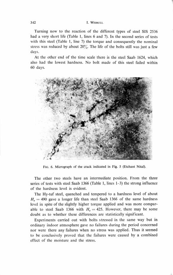
Fla. 6. Micrograph of the crack indicated in Fig. 5 (Etchant Nital).
The other two steels have an intermediate position. From the threeseries of tests with steel Saab 1366 (Table 1, lines 1-3) the strong influenceof the hardness level is evident.
The Hy-tuf steel, quenched and tempered to a hardness level of about= 490 gave a longer life than steel Saab 1366 of the same hardness
level in spite of the slightly higher torque applied and was more compar-able to steel Saab 1366 with I = 425. However, there may be somedoubt as to whether these differences are statistically significant.
Experiments carried out with bolts stressed in the same way but inordinary indoor atmosphere gave no failures during the period concernednor were there any failures when no stress was applied. Thus it seemedto be conclusively proved that the failures were caused by a combinedeffect of the moisture and the stress.
Stress Corrosion Cracking in High Strength Steel 343
CORROSION TESTS WITH WET SPECIMENS
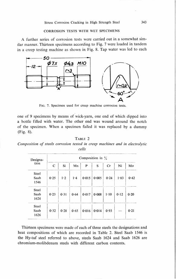
A further series of corrosion tests were carried out in a somewhat sim-ilar manner. Thirteen specimens according to Fig. 7 were loaded in tandemin a creep testing machine as shown in Fig. 8. Tap water was led to each
50
1207.5 043 h1/0
FIG. 7. Specimen used for creep machine corrosion tests.
one of 9 specimens by means of w ick-yarn, one end of which dipped intoa bottle filled with water. The other end was wound around the notchof the specimen. When a specimen failed it was replaced by a dummy(Fig. 8).
TABLE 2 Composition of steels corrosion tested in creep machines and in electrolytic
cells
Designa-
Composition in
tion
Si Mn
Cr Ni Mo
;
Steel
Saab 0.25 1.7 P4 0-015 0-005 0-24 1.83 0-421546
Steel
Saab 0.23 0-31 0-64 0.017 0-008 1.10 0.12 0-201624
Steel
Saab 0.32 0-28 0-65 0-0160.014 0-93 — 0.211626
Thirteen specimens were made of each of three steels the designations andheat compositions of which are recorded in Table 2. Steel Saab 1546 isthe Hy-tuf steel referred to above, steels Saab 1624 and Saab 1626 arechromium-molibdenum steels with different carbon contents.
344 I. WEIBULL
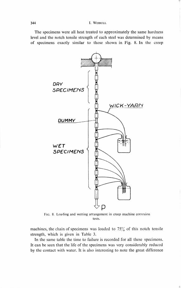
The specimens were all heat treated to approximately the same hardnesslevel and the notch tensile strength of each steel was determined by meansof specimens exactly similar to those shown in Fig. 8. In the creep
DRYSPECIMENS
WICK-YARN
DUMMY
WETSPECIMENS
FIG. 8. Loading and wetting arrangement in creep machine corrosion tests.
machines, the chain of specimens was loaded to 75% of this notch tensilestrength, which is given in Table 3.
In the same table the time to failure is recorded for all these specimens.It can be seen that the life of the specimens was very considerably reducedby the contact with water. It is also interesting to note the great difference
Stress Corrosion Cracking in High Strength Steel 345
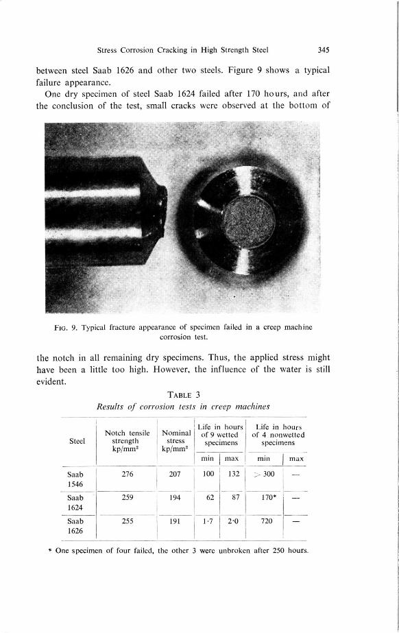
between steel Saab 1626 and other two steels. Figure 9 shows a typicalfailure appearance.
One dry specimen of steel Saab 1624 failed after 170 hours, and afterthe conclusion of the test, small cracks were observed at the bottom of
FIG. 9. Typical fracture appearance of specimen failed in a creep machine corrosion test.
the notch in all remaining dry specimens. Thus, the applied stress mighthave been a little too high. However, the influence of the water is stillevident.
TABLE 3Results of corrosion tests in creep machines
Life in hoursof 9 wettedspecimens
Life in hours of 4 nonwetted
specimensNotch tensile
strengthkp/mm2
Nominal stress
kp/mm2Steel
min max min max
207 100 132 - - 300I -
170*
1.7 2.0 7201626
Saab 1546
Saab 1624
Saab
276
259
255
194
191
62 87
* One specimen of four failed, the other were unbroken after 250 hours.
346 I. WEIBULL
THE MECHANISM OF FAILURE
The results of the humidity cabinet tests do not necessarily mean thatthey were stress corrosion cracking phenomena in the true sense of thisconcept. It could also be possible that a small amount of hydrogen gener-ated by the corrosion process had caused local brittleness and thus hadstarted the failure.
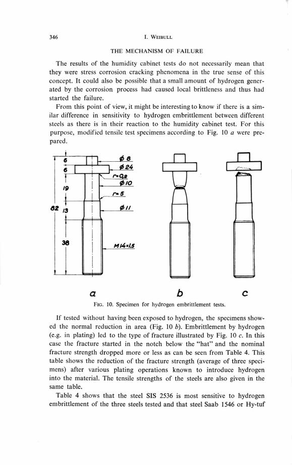
From this point of view, it might be interesting to know if there is a sim-ilar difference in sensitivity to hydrogen embrittlement between differentsteels as there is in their reaction to the humidity cabinet test. For thispurpose, modified tensile test specimens according to Fig. 10 a were pre-pared.
68246
r.
/90 /0
r. 5
82 /3 0 //
38 /4 /4 4.5
aFIG. 10. Specimen for hydrogen embrittlement tests.
If tested w ithout having been exposed to hydrogen, the specimens show-ed the normal reduction in area (Fig. 10 b). Embrittlement by hydrogen(e.g. in plating) led to the type of fracture illustrated by Fig. 10 c. In thiscase the fracture started in the notch below the "hat" and the nominalfracture strength dropped more or less as can be seen from Table 4. Thistable shows the reduction of the fracture strength (average of three speci-mens) after various plating operations known to introduce hydrogeninto the material. The tensile strengths of the steels are also given in thesame table.
Table 4 shows that the steel SIS 2536 is most sensitive to hydrogenembrittlement of the three steels tested and that steel Saab 1546 or Hy-tuf
Stress Corrosion Cracking in High Strength Steel 347
was not affected at all in this type of test. Thus the three steels rank in
the same order as in the humidity cabinet test.
A failure showing some features in common with those mentioned
above, was reported by Shank et al.(O Some rocket chambers failed during
hydrostatic water pressure tests. The extensive investigation carried out
TABLE 4
Results of hydrogen embrittlement tests with modified tensile test specimens (Fig. I l)
Steel
Saab Saab
1366 1546 SIS
(Hy-tuf) 2536
Tensile strength, kp/m2 180 168 188
Reduction in %, by:
No plating 0 o 0
Cadmium plating, no baking 35 o 50
Cadmium plating, baking 17 h at 170-C 0 o 5
Acid zinc plating, no baking
o 20
to find the cause of these failures revealed a number of facts pointing
to hydrogen embrittlement. It was assumed that the hydrogen had been
generated by local corrosion, though the mechanism of hydrogen charging
was not fully understood.
41 CC
-J
1-47:1 /
IILU
2,z
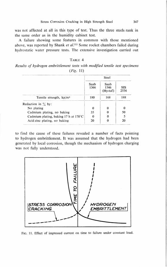
;7:STRESS CORROSIOPI / HYDROGENCRACKING EMBRITTLEMEPIT
•• •••
•••••
Ftc. 11 . Effect of impressed current on time to failure under constant load.
348 I. WEIBULL
This is probably because in steel corrosion in neutral water solutionsthe dominating cathodic reaction is oxygen reduction(2), that is the reaction
024-4e-F2H00 - 40H-
and not hydrogen evolution
2H+ 1-2e
Therefore it seems that the assumption of hydrogen embrittlement asa failure cause in these cases needs further support.
This support may be given by experiments according to a method usedby B. F. Brown at the Naval Research Laboratory, Washington andothers(3.4). The material to be investigated is made one electrode in anelectrolytic cell, containing the corroding solution concerned. With thetest material under stress, a current is brought to flow through the cell.If, with the test material as cathode, the time to failure decreases con-tinuously with increasing current, the failure is ascribed to hydrogenembrittlement. On the other hand the failures are stress corrosion crackingphenomena, if the time to failure decreases with increasing current andwith the test material as anode. This may be further illustrated by Fig. 11.
ELECTROLYTIC CELL EXPERIMENTS
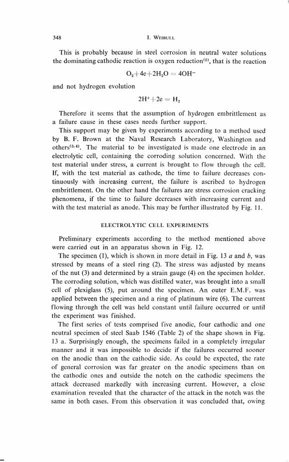
Preliminary experiments according to the method mentioned abovewere carried out in an apparatus shown in Fig. 12.
The specimen (1), which is shown in more detail in Fig. 13 a and b, wasstressed by means of a steel ring (2). The stress was adjusted by meansof the nut (3) and determined by a strain gauge (4) on the specimen holder.The corroding solution, which was distilled water, was brought into a smallcell of plexiglass (5), put around the specimen. An outer E.M.F. wasapplied between the specimen and a ring of platinum wire (6). The currentflowing through the cell was held constant until failure occurred or untilthe experiment was finished.
The first series of tests comprised five anodic, four cathodic and oneneutral specimen of steel Saab 1546 (Table 2) of the shape shown in Fig.13 a. Surprisingly enough, the specimens failed in a completely irregularmanner and it was impossible to decide if the failures occurred sooneron the anodic than on the cathodic side. As could be expected, the rateof general corrosion was far greater on the anodic specimens than onthe cathodic ones and outside the notch on the cathodic specimens theattack decreased markedly with increasing current. However, a closeexamination revealed that the character of the attack in the notch was thesame in both cases. From this observation it was concluded that, owing
Stress Corrosion Cracking in High Strength Steel 349
to the poor conductivity and throwing power of the electrolyte (distilled
water) the notch area did not react in a truly cathodic manner. This fact
probably explained the lack of difference in time to failure between the
anodic and the cathodic specimens.
2
3
so
FIG. 12. Apparatus for electrolytic cell corrosion tests.
In weak electrolytes like distilled water, only small amounts of hydro-
gen will be generated, thus prolonging the time to failure. The hydrogen
atoms entering the steel are assumed to diffuse to the area of maximum
stress(1(5>, which is close to the bottom of the notch. The effect of this
is, that the time to failure under sustaining load is very much shorter for
a notched specimen than for an unnotched one.
For this reason it was decided still to use notched cathodic specimens
but the notch was covered with a thin layer of wax.
I ,
1 k3,„
350 J. WEIBULL
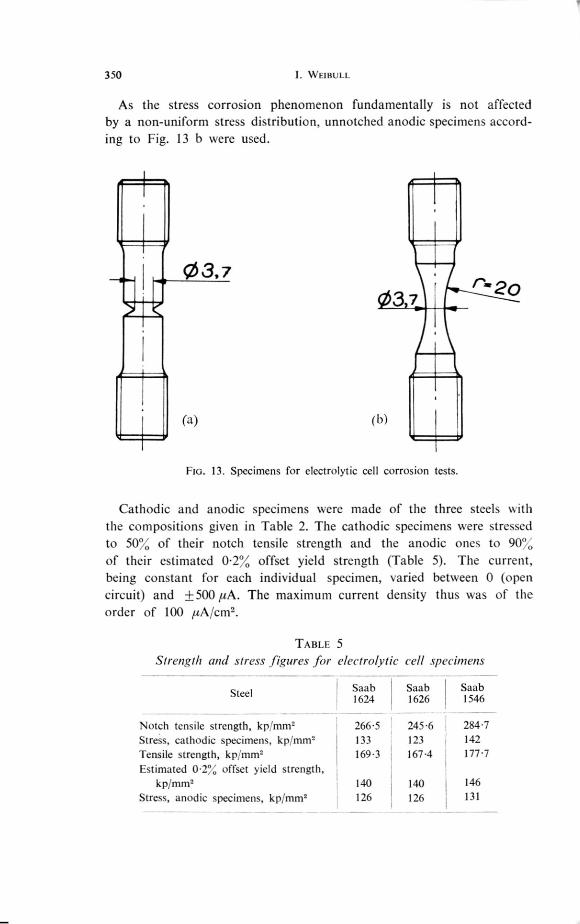
As the stress corrosion phenomenon fundamentally is not affected
by a non-uniform stress distribution, unnotched anodic specimens accord-
ing to Fig. 13 b were used.
0 3, 7rar 2o
3 7
(a) (b)
Fla. 13. Specimens for electrolytic cell corrosion tests.
Cathodic and anodic specimens were made of the three steels with
the compositions given in Table 2. The cathodic specimens were stressed
to 50% of their notch tensile strength and the anodic ones to 90%of their estimated 0.2%, offset yield strenRth (Table 5). The current,
being constant for each individual specimen, varied between 0 (open
circuit) and +500 //A. The maximum current density thus was of the
order of 100 pA/cm2.
TABLE 5 Strength and stress figures for electrolytic cell specimens
SteelSaab 1624
266.5133169.3
140126
Saab1626
245.6123167.4
140 126
Saab1546
284.7142177.7
146 131
Notch tensile strength, kp!mm2Stress, cathodic specimens, kplmrn2Tensile strength, kplmmEstimated 0.2% offset yield strength,
kp/mm2Stress, anodic specimens, kp/mm2
Stress Corrosion Cracking in High Strength Steel 351
> 1000 612709
200
TIME TOFAILURE,HOURS
150
100
50
0
0
0
1000HOURS
500
110
L _
0
1
,u A1000
0 100 200 300 400 500CURRENT, tuA
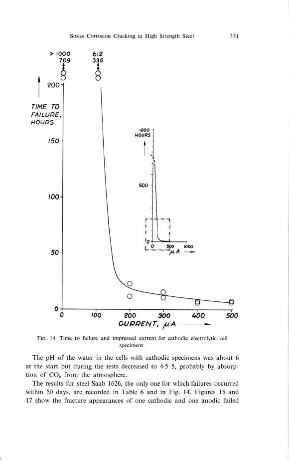
FIG. 14. Time to failure and impressed current for cathodic electrolytic cell specimens.
The pH of the water in the cells with cathodic specimens was about 6at the start but during the tests decreased to 4-5-5, probably by absorp-tion of CO, from the atmosphere.
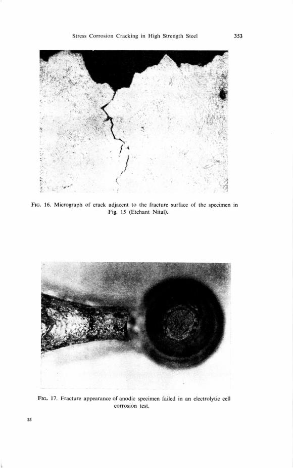
The results for steel Saab 1626, the only one for which failures occurredwithin 50 days, are recorded in Table 6 and in Fig. 14. Figures 15 and17 show the fracture appearances of one cathodic and one anodic failed
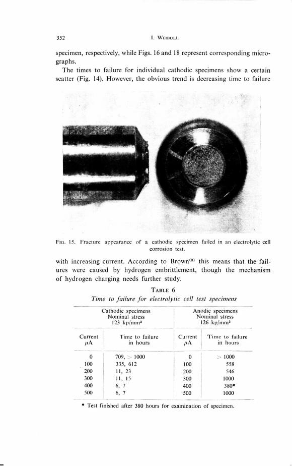
352 I. WFIBULL
specimen, respectively, while Figs. 16 and 18 represent corresponding micro-
graphs.
The times to failure for individual cathodic specimens show a certa inscatter (Fig. 14). However, the obvious trend is decreasing time to failure
FIG. 15. Fracture appearance of a cathodic specimen failed in an electrolytic cellcorrosion test.
with increasing current. According to Brown(3) this means that the fail-ures were caused by hydrogen embrittlement, though the mechanism
of hydrogen charging needs further study.
TABLE 6
Time to failure for electrolytic cell test specimens
Cathodic specimens Anodic specimens
Nominal stress Nominal stress
123 kp/mm2 126 kp/mm2
Current itA
Time to failure in hours
CurrentILA
Time to failure in hours
0 709,1000 0 1000
100 335, 612 100 558
200 11,23 200 546
300 11,15 300 1000
400 6, 7 400 380*
500 6, 7 500 1000
* Test finished after 380 hours for examination of specimen.
Stress Corrosion Cracking in High Strength Steel 353
FIG. 16. Micrograph of crack adjacent to the fracture surface of the specimen inFig. 15 (Etchant Nital).
FIG. 17. Fracture appearance of anodic specimen failed in an electrolytic cell corrosion test.
23
354 1. WEIBULL
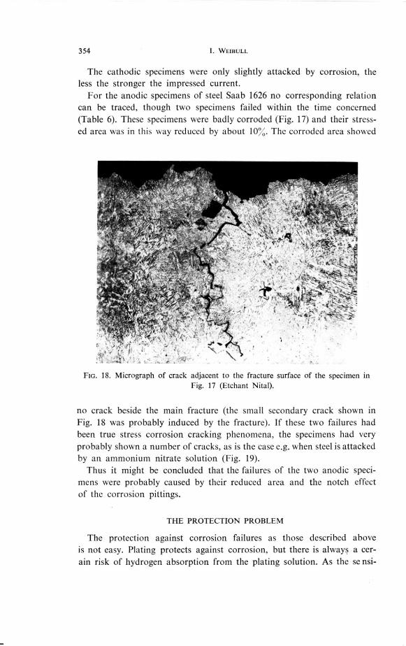
The cathodic specimens were only slightly attacked by corrosion, the
less the stronger the impressed current.
For the anodic specimens of steel Saab 1626 no corresponding relation
can be traced, though two specimens failed within the time concerned
(Table 6). These specimens were badly corroded (Fig. 17) and their stress-
ed area was in this way reduced by about 10%. The corroded area showed
FIG. 18. Micrograph of crack adjacent to the fracture surface of the specimen inFig. 17 (Etchant Nital).
no crack beside the main fracture (the small secondary crack shown in
Fig. 18 was probably induced by the fracture). If these two failures had
been true stress corrosion cracking phenomena, the specimens had very
probably shown a number of cracks, as is the case e.g. when steel is attacked
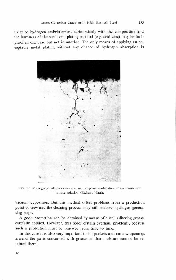
by an ammonium nitrate solution (Fig. 19).Thus it might be concluded that the failures of the two anodic speci-
mens were probably caused by their reduced area and the notch effect
of the corrosion pittings.
THE PROTECTION PROBLEM
The protection against corrosion failures as those described above
is not easy. Plating protects against corrosion, but there is always a cer-ain risk of hydrogen absorption from the plating solution. As the se nsi-
Stress Corrosion Cracking in High Strength Steel 355
tivity to hydrogen embrittlement varies widely with the composition and
the hardness of the steel, one plating method (e.g. acid zinc) may be fool-
proof in one case but not in another. The only means of applying an ac-
ceptable metal plating w ithout any chance of hydrogen absorption is
FIG. 19. Micrograph of cracks in a specimen exposed under stress to an ammonium nitrate solution (Etchant NitaD.
vacuum deposition. But this method offers problems from a production
point of view and the cleaning process may still involve hydrogen genera-ting steps.
A good protection can be obtained by means of a well adhering grease,
carefully applied. However, this poses certain overhaul problems, because
such a protection must be renewed from time to time.
In this case it is also very important to fill pockets and narrow openings
around the parts concerned with grease so that moisture cannot be re-
tained there.
23.
356 I. WEIBULL
CONCLUSIONS
The follow ing conclusions seem to be justified :The brittle failures observed in non-plated threaded bolts of highstrength steel were probably caused by hydrogen, generated byatmospheric moisture corrosion. The CO2 content of the atmospheremay play a part in this connection.The sensitivity to such failures and to hydrogen embrittlement ingeneral is very different for steels of different compositions andhardness levels.Protection against such failures is necessary but should not introducea risk of hydrogen absorption during the protection process. Fromthis point of view, application of grease or vacuum deposition ofa metallic coating are to be preferred, but may pose practical problems.
REFERENCES
SHANK, M. E., SPAETH, C. E., COOKE, V. W. and COYNE,J. E., Solid-Fuel RocketChambers for Operation at 24-0,000 psi and Above, Metal Progress, November 1959,pp. 74-81, December 1959, pp. 84-92.EVANS, U. R., The Corrosion and Oxidation of Metals, London 1960, pp. 88, 91,309.BROWN, B. F., NRL Progress, May 1959, pp. 40-42.NAUM ANN, F. K. and CARIUS, W., Bruchbildung an Stählen bei Einwirkung vonSclmefelwasserstoff„4rchiv fiir das Eisenhiittenwesen, April 1959, pp. 233-238,May 1959, pp. 283-292, June 1959, pp. 361-370.MORLE r, J. G., JOHNSON, H. H. and TROIANO, A. R., A New Concept of HydrogenEmbrittlement in Steel, WADC Technical Report 57-190, March 1957.