Embed Size (px)
Citation preview

Corrosion Science 100 (2015) 619–626
Contents lists available at ScienceDirect
Corrosion Science
j ourna l h omepage: www.elsev ier .com/ locate /corsc i
Stress corrosion cracking at low loads: Surface slip andcrystallographic analysis
Longkui Zhua,b, Yu Yana, Jinxu Lia, Lijie Qiaoa,∗, Zhengcao Lib, Alex A. Volinskyc
a Corrosion and Protection Center, Key Laboratory for Environmental Fracture (MOE), University of Science and Technology Beijing, Beijing 100083, People’sRepublic of Chinab Key Laboratory of Advanced Materials, School of Materials Science and Engineering, Tsinghua University, Beijing 100084, People’s Republic of Chinac Department of Mechanical Engineering, University of South Florida, Tampa, Florida 33620, USA
a r t i c l e i n f o
Article history:Received 27 May 2015Received in revised form 23 August 2015Accepted 24 August 2015Available online 28 August 2015
Keywords:A. Stainless steelB. SEMB. Modelling studiesC. Stress corrosionC. Anodic dissolutionC. Effects of strains
a b s t r a c t
Stress corrosion cracking (SCC) of 316 L single crystal was studied by scanning electron microscopy andelectron backscatter diffraction. SCC could initiate and propagate without surface slip at the normalstress of 20 MPa. The cracks grew on the {1 0 0} planes. Many microvoids appeared at the slip bands andmicrosteps were present on the fracture surfaces. Consequently, the synergistic effects of microcleavageand local dissolution induced SCC advance on {1 0 0} crystal planes. Microshear was an additional SCCmicroscopic mechanism at high stress levels.
© 2015 Elsevier Ltd. All rights reserved.
1. Introduction
Stress corrosion cracking (SCC) experiments conducted duringthe last few decades show that environmental fracture in ductileface centered cubic (FCC) materials is the consequence of localizedinteractions between corrosion and dislocations [1–5]. Namely,local dissolution induces new stress concentrations, favoring theemission of dislocations and the formation of slip steps [3,6]. On theother hand, dislocations move to surfaces or slip steps and disruptsurface protective films. Then dislocations emerge on the surfaceand freshly exposed metal is chemically attacked [2,7–14]. How-ever, a novel SCC phenomenon has been observed where SCC cracksinitiated and grew without any surface slip bands under low loads[15–17]. It is considered that dislocation pile-ups play an impor-tant role in the SCC process, and the emergence of slip bands isjust an accompanying result at high stress levels, not contributingdirectly to SCC [15]. As proposed by the corrosion-enhanced plas-ticity model (CEPM), the increasing localized stresses by dislocationpile-ups and the decreasing critical stress intensity factor, KISCC dueto hydrogen, jointly lead to the initiation of microcracks ahead ofthe main crack tip [5–6,18–21]. Therefore, it is likely to form an SCC
∗ Corresponding author. Fax: +86 10 6233 2345.E-mail addresses: [email protected] (L. Qiao), [email protected] (A.A. Volinsky).
crack via dislocation pile-ups. Another explanation for SCC withoutany slip bands is that brittle films formed by anodic dissolution canbreak at small strains before the base metal yielding [12]. Indeed,the comparison of elastic behavior of the aircraft structural A97075Al-alloy and bulk Al2O3 oxide demonstrates that the fracture strainof aluminum oxide, �f = 0.0007, is much less than the elastic limitof the aluminum alloy, �YS = 0.002 [12,22]. Consequently, it is alsopossible that local dissolution takes place at the crack tip and filmrupture promotes SCC advance with no slip bands emerging on thebase metal.
In general, SCC cracks induced by selective dissolution and dislo-cation motion often propagate along crystal planes. For FCC metals,the slip planes are {1 1 1}. It is suggested by the CEPM and the slip-dissolution model that SCC sometimes occurs on the {1 1 1} planesof austenitic stainless steel in boiling MgCl2 solutions [5–8,18–21].Magnin et al. studied SCC of 316 alloys in the 153 ◦C boiling MgCl2solution, and suggested that transgranular cracking was related toboth microshear on the {1 1 1} planes and microcleavage mainlyon the {1 0 0} planes [6]. Li et al. employed etch-pitting and stere-ographic observations to determine the SCC crystallography of thesame SCC system, finding that cracking occurred predominantly onthe {1 0 0} planes at low K values [23]. In 304 L and 310 stainlesssteels, SCC cracks occurred primarily on the {1 0 0} planes, whilesecondary cracks on the {1 1 0} planes were also found [24–26].Besides, a number of SCC microcracks initiated at the crossing of
http://dx.doi.org/10.1016/j.corsci.2015.08.0400010-938X/© 2015 Elsevier Ltd. All rights reserved.

620 L. Zhu et al. / Corrosion Science 100 (2015) 619–626
Fig. 1. Schematics of 316 L stainless steel single crystal specimens (dimensions arein mm).
two groups of the slip bands and did not follow the {1 1 1} slipplanes [2,15,27–28]. Thus, it is probable for SCC cracks to growalong a few low index planes, except the {1 1 1} slip planes. Inother words, without surface slip, preferential dissolution or micro-cleavage can occur on some crystal planes, such as {1 0 0} for 304 Land {1 1 0} for copper due to the lowest surface energy [24,29].Moreover, in crystals with the small Schmid’s factor, the low shearstress well below the critical shear stress value, is applied to the{1 1 1} slip planes, and no slip takes place [5]. In this circumstance,other crystal planes are possibly subjected to high normal stressand fracture via local dissolution or microcleavage.
Although, lots of research has been conducted on FCC metals slipand crystallography in the past few years, it is essential to correlateSCC and surface slip bands, along with the SCC crystallographic fea-tures. In this work, slip bands were investigated on the specimensurfaces with or without short and long SCC cracks. SCC crystal-lography was characterized by the two-surface trace analysis todetermine whether cracks followed the {1 1 1} slip planes. Finally,microscopic SCC mechanisms of austenitic stainless steel in boilingMgCl2 solutions are discussed at low and high stress levels.
2. Experimental procedure
316 L SS single crystals were used in this study with thefollowing chemical composition: 0.007 wt.% C, 17.00 wt.% Cr,13.49 wt.% Ni, 2.54 wt.% Mo, 0.66 wt.% Mn, 0.46 wt.% Si, 0.008 wt.% P,0.0056 wt.% S and Fe balance. The crystals were produced along the[001] direction and machined into 0.7 mm thick specimens withcircle holes 2 mm in diameter, as shown schematically in Fig. 1.Prior to experiments, the specimens were annealed at 1050 ◦C for30 min in argon, water-quenched, ground using 2000 grit emerypaper, electrochemically thinned to about 0.5 mm in solution con-taining H3PO4, H2SO4, CrO3, and C2H6O2 (glycol), degreased withacetone in an ultrasonic cleaner and washed with deionized water.After the pretreatment, the samples were placed into a glass con-tainer filled with a boiling 45 wt.% MgCl2 solution. Normal stress ofeither 20 MPa or 40 MPa, calculated in terms of the narrowest sec-tion (2 × 0.5 mm2), was applied to the specimens. All experimentswere carried out under an open circuit condition using a constantload weight-type apparatus with a cooling system, two 316 L SSsingle crystal pins and two silica grips.
Fig. 2. Schematic diagram of the two-surface trace analysis characterizing the crys-tallography of the 316 L single crystal cracking plane, where M and M′ are the labelson the first and second surfaces, respectively. �1 and �2 are the angles between thecrack and the [u0 v0 w0] crystal orientation, while ϕ1 and ϕ2 are the angles betweenthe cracking plane and the first surface. The [u0 v0 w0] crystallography of the firstsurface was determined by electron backscatter diffraction.
Fig. 3. Surface morphology of the specimens with cleaned off corrosion products,subjected to normal stress of: (a) 40 MPa and (b) 20 MPa. The slip band was corrodedand lots of microvoids emerged at the slip band. However, there was no slip bandon the surface in Fig. 3(b).
After 200–300 h, SCC cracks grew to a certain size and speci-mens were taken out from the glass container. Some specimenswere ultrasonically cleaned in deionized water as well as 5 wt.%HCl + 2 g/L hexamethylenetetramine mixture to remove corrosionproducts from the specimen surface. Both cleaned and virgin sam-ples were employed to examine the slip bands and SCC cracks byscanning electron microscopy (SEM). To correlate surface slip andSCC propagation, it was checked whether the slip bands appearedin nucleation areas and near crack tips of short and long cracks. The
L. Zhu et al. / Corrosion Science 100 (2015) 619–626 621
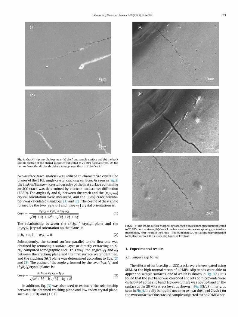
Fig. 4. Crack 1 tip morphology near (a) the front sample surface and (b) the backsample surface of the etched specimen subjected to 20 MPa normal stress. On thetwo surfaces, the slip bands did not emerge near the tip of the Crack 1.
two-surface trace analysis was utilized to characterize crystallineplanes of the 316L single crystal cracking surfaces. As seen in Fig. 2,the (h0k0l0)[u0v0w0] crystallography of the first surface containingan SCC crack was determined by electron backscatter diffraction(EBSD). The angles �1 and �2 between the crack and the [u0v0w0]crystal orientation were measured, and the [uvw] crack orienta-tion was calculated using Eqs. (1) and (2) . The cosine of the � angleformed by the two [u1v1w1] and [u2v2w2] crystal orientations is:
cos� = u1u2 + v1v2 + w1w2√u2
1 + v21 + w2
1 +√
u22 + v2
2 + w22
(1)
The relationship between the (h1k1l1) crystal plane and the[u1v1w1]crystal orientation on the plane is:
u1h1 + v1k1 + w1l1 = 0 (2)
Subsequently, the second surface parallel to the first one wasobtained by removing a surface layer or directly extracting an X-ray computed tomographic slice. This way, the angles ϕ1 and ϕ2between the cracking plane and the first surface were identified,and the cracking (hkl) plane was determined according to Eqs. (2)and (3). The cosine of the angle ϕ formed by the two (h1k1l1) and(h2k2l2)crystal planes is:
cosϕ = h1h2 + k1k2 + l1l2√h2
1 + k21 + l21
√h2
2 + k22 + l22
(3)
In addition, Eq. (3) was also used to estimate the relationshipbetween the obtained cracking plane and low index crystal plane,such as {1 0 0} and {1 1 1}.
Fig. 5. (a) The whole surface morphology of Crack 2 in a cleaned specimen subjectedto 20 MPa normal stress; (b) Crack 1 nucleation area surface morphology; (c) surfacemorphology near the tip of the Crack 1. It is found that SCC initiation and propagationtook place without the surface slip bands at low load.
3. Experimental results
3.1. Surface slip bands
The effects of surface slip on SCC cracks were investigated usingSEM. At the high normal stress of 40 MPa, slip bands were able toappear on sample surfaces, one of which is shown in Fig. 3(a). It isfound that the slip band was corroded and lots of microvoids weredistributed at the slip band. However, there was no slip band on thesurface at the 20 MPa stress level, as shown in Fig. 3(b). Similarly, asseen in Fig. 4, the slip bands did not emerge near the tip of Crack 1 onthe two surfaces of the cracked sample subjected to the 20 MPa nor-

622 L. Zhu et al. / Corrosion Science 100 (2015) 619–626
Fig. 6. (a) The whole original surface of Cracks 3 and 4 in a specimen subjected to 20 MPa normal stress; (b) Crack 3 nucleation area surface morphology; (c) surfacemorphology near the tip of the Crack 3; (d) Crack 4 nucleation area surface morphology; (e) the surface morphology near the tip of the Crack 4. No surface slip band wasobserved near the Crack 3, while the slip bands emerged around the tip of the Crack 4.
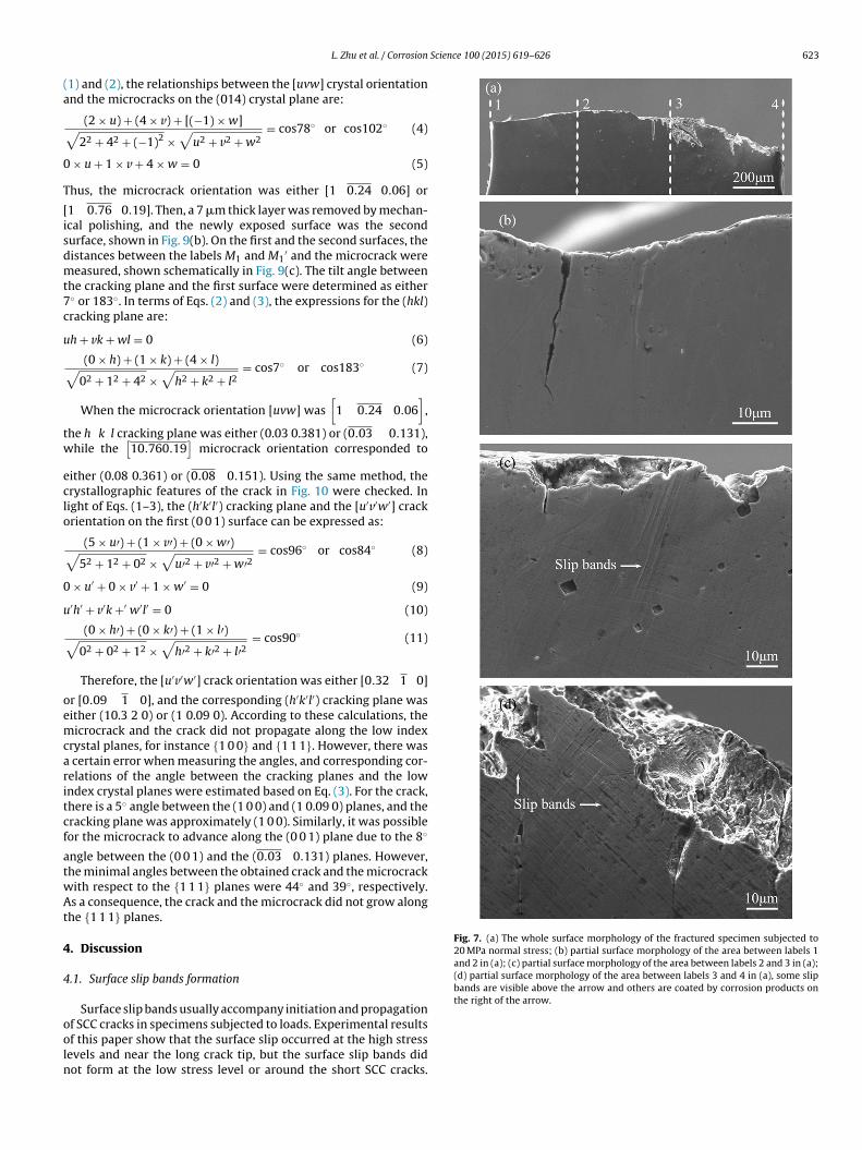
mal stress, meaning that SCC initiation and propagation could takeplace without the surface slip bands for the low load conditions.Then, the surface slip was examined in nucleation areas and nearthe crack tips of the specimens under the 20 MPa normal stress,shown in Fig. 5 and Fig. 6. As seen in Fig. 5, the Crack 2 was about0.1 mm in length and there was no slip band around the crack. Sim-ilarly, on the virgin specimen in Fig. 6, slip bands did not emergein the nucleation area and near the tip of approximately 0.5 mmlong Crack 3. The Crack 4 was roughly 1.5 mm in length and the slipbands were formed near the crack tip rather than in the nucleationarea of the Crack 4. Thus, the Crack 4 did not propagate along theslip bands, as seen in Fig. 6(a), (d) and (e). As a consequence, the sur-face slip was capable of forming again when the crack extended toa critical size in the specimen subjected to low applied stress levels.The sample and the fracture surface morphology was observed onthe same specimen loaded with the 20 MPa normal stress, shown inFig. 7 and Fig. 8, respectively. No surface slip bands could be foundin the area between labels 1 and 2 in Fig. 7(a), as seen in Fig. 7(b).Then, the fracture surface of the same area was observed by SEM,finding that no macroscopic deformation occurred in the specimen
and lots of microsteps together with several tear ridges are seen inFig. 8(a) and (b). The areas between the labels 2 and 3, and between2′ and 3′ were examined, shown in Fig. 7(a), (c) and Fig. 8(a), (c),respectively. Numerous slip bands, microsteps and tear ridges werepresent and the specimen was slightly deformed.
Finally, the crack propagated in the area between labels 3 and4. As seen in Fig. 7(a), (d) and Fig. 8(a), (d), some secondary cracksand necking were detected in addition to the surface slip bands,microsteps and tear ridges, while cracks did not extend along thesurface slip bands.
3.2. SCC crystallographic features
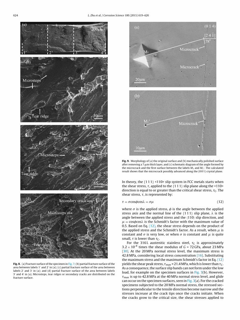
The two-surface trace analysis was used to characterize crys-tallographic feathers of the cracking planes. As seen in Fig. 9, thefirst surface containing microcracks was the (014) crystal plane
detected by EBSD. The angle between the [2 4 1] crystal orienta-tion and the microcracks was either 78◦ or 102◦. According to Eqs.
L. Zhu et al. / Corrosion Science 100 (2015) 619–626 623
(1) and (2), the relationships between the [uvw] crystal orientationand the microcracks on the (014) crystal plane are:
(2 × u) + (4 × v) + [(−1) × w]√22 + 42 + (−1)2 ×
√u2 + v2 + w2
= cos78◦ or cos102◦ (4)
0 × u + 1 × v + 4 × w = 0 (5)
Thus, the microcrack orientation was either [1 0.24 0.06] or
[1 0.76 0.19]. Then, a 7 �m thick layer was removed by mechan-ical polishing, and the newly exposed surface was the secondsurface, shown in Fig. 9(b). On the first and the second surfaces, thedistances between the labels M1 and M1
′ and the microcrack weremeasured, shown schematically in Fig. 9(c). The tilt angle betweenthe cracking plane and the first surface were determined as either7◦ or 183◦. In terms of Eqs. (2) and (3), the expressions for the (hkl)cracking plane are:
uh + vk + wl = 0 (6)
(0 × h) + (1 × k) + (4 × l)√02 + 12 + 42 ×
√h2 + k2 + l2
= cos7◦ or cos183◦ (7)
When the microcrack orientation [uvw] was[
1 0.24 0.06]
,
the h k l cracking plane was either (0.03 0.381) or (0.03 0.131),while the
[10.760.19
]microcrack orientation corresponded to
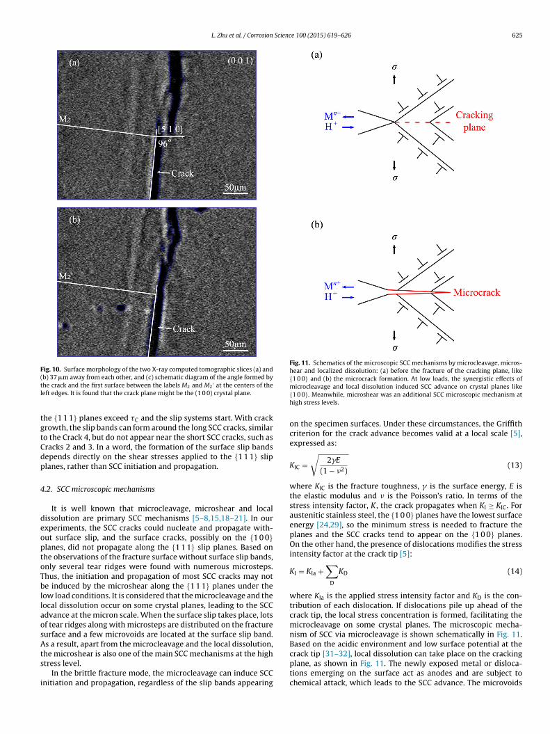
either (0.08 0.361) or (0.08 0.151). Using the same method, thecrystallographic features of the crack in Fig. 10 were checked. Inlight of Eqs. (1–3), the (h′k′l′) cracking plane and the [u′v′w′] crackorientation on the first (0 0 1) surface can be expressed as:
(5 × u′) + (1 × v′) + (0 × w′)√52 + 12 + 02 ×
√u′2 + v′2 + w′2
= cos96◦ or cos84◦ (8)
0 × u′ + 0 × v′ + 1 × w′ = 0 (9)
u′h′ + v′k +′ w′l′ = 0 (10)
(0 × h′) + (0 × k′) + (1 × l′)√02 + 02 + 12 ×
√h′2 + k′2 + l′2
= cos90◦ (11)
Therefore, the [u′v′w′] crack orientation was either [0.32 1 0]
or [0.09 1 0], and the corresponding (h′k′l′) cracking plane waseither (10.3 2 0) or (1 0.09 0). According to these calculations, themicrocrack and the crack did not propagate along the low indexcrystal planes, for instance {1 0 0} and {1 1 1}. However, there wasa certain error when measuring the angles, and corresponding cor-relations of the angle between the cracking planes and the lowindex crystal planes were estimated based on Eq. (3). For the crack,there is a 5◦ angle between the (1 0 0) and (1 0.09 0) planes, and thecracking plane was approximately (1 0 0). Similarly, it was possiblefor the microcrack to advance along the (0 0 1) plane due to the 8◦
angle between the (0 0 1) and the (0.03 0.131) planes. However,the minimal angles between the obtained crack and the microcrackwith respect to the {1 1 1} planes were 44◦ and 39◦, respectively.As a consequence, the crack and the microcrack did not grow alongthe {1 1 1} planes.
4. Discussion
4.1. Surface slip bands formation
Surface slip bands usually accompany initiation and propagationof SCC cracks in specimens subjected to loads. Experimental resultsof this paper show that the surface slip occurred at the high stresslevels and near the long crack tip, but the surface slip bands didnot form at the low stress level or around the short SCC cracks.
Fig. 7. (a) The whole surface morphology of the fractured specimen subjected to20 MPa normal stress; (b) partial surface morphology of the area between labels 1and 2 in (a); (c) partial surface morphology of the area between labels 2 and 3 in (a);(d) partial surface morphology of the area between labels 3 and 4 in (a), some slipbands are visible above the arrow and others are coated by corrosion products onthe right of the arrow.
624 L. Zhu et al. / Corrosion Science 100 (2015) 619–626
Fig. 8. (a) Fracture surface of the specimen in Fig. 7; (b) partial fracture surface of thearea between labels 1′ and 2′ in (a); (c) partial fracture surface of the area betweenlabels 2′ and 3′ in (a); and (d) partial fracture surface of the area between labels3′ and 4′ in (a). Microsteps, tear ridges or secondary cracks are distributed on thefracture surface.
Fig. 9. Morphology of (a) the original surface and (b) mechanically polished surfaceafter removing a 7 �m thick layer, and (c) schematic diagram of the angle formed bythe microcrack and the first surface between the labels M1 and M1
′ . The calculatedresult shows that the microcrack possibly advanced along the (0 0 1) crystal plane.
In theory, the {1 1 1} <110> slip system in FCC metals starts whenthe shear stress, �, applied to the {1 1 1} slip plane along the <110>direction is equal to or greater than the critical shear stress, �C. Theshear stress, �, is represented by:
� = �cos�cos� = � (12)
where � is the applied stress, � is the angle between the appliedstress axis and the normal line of the {1 1 1} slip plane, � is theangle between the applied stress and the 〈110〉 slip direction, and = cos�cos� is the Schmidt’s factor with the maximum value of0.5. Based on Eq. (12), the shear stress depends on the product ofthe applied stress and the Schmidt’s factor. As a result, when isconstant and � is very low, or when � is constant and is quitesmall, � is lower than �C.
For the 316 L austenitic stainless steel, �C is approximately3.2 × 10-4 times the shear modulus of G = 72 GPa, about 23 MPa[30]. At the 20 MPa normal stress level, the maximum stress is42.8 MPa, considering local stress concentration [16]. Substitutingthe maximum stress and the maximum Schmidt’s factor in Eq. (12)yields the shear peak stress, �max = 21.4 MPa, which is lower than �C.As a consequence, the surface slip bands can not form under the lowload, for example on the specimen surfaces in Fig. 3(b). However,�max is up to 42.8 MPa at the 40 MPa normal stress level, and glidecan occur on the specimen surfaces, seen in Fig. 3(a). For the crackedspecimens subjected to the 20 MPa normal stress, the stressed sec-tions perpendicular to the tensile direction become narrow and thestresses increase at the crack tips once the cracks initiate. Whenthe cracks grow to the critical size, the shear stresses applied to
L. Zhu et al. / Corrosion Science 100 (2015) 619–626 625
Fig. 10. Surface morphology of the two X-ray computed tomographic slices (a) and(b) 37 �m away from each other, and (c) schematic diagram of the angle formed bythe crack and the first surface between the labels M2 and M2
′ at the centers of theleft edges. It is found that the crack plane might be the (1 0 0) crystal plane.
the {1 1 1} planes exceed �C and the slip systems start. With crackgrowth, the slip bands can form around the long SCC cracks, similarto the Crack 4, but do not appear near the short SCC cracks, such asCracks 2 and 3. In a word, the formation of the surface slip bandsdepends directly on the shear stresses applied to the {1 1 1} slipplanes, rather than SCC initiation and propagation.
4.2. SCC microscopic mechanisms
It is well known that microcleavage, microshear and localdissolution are primary SCC mechanisms [5–8,15,18–21]. In ourexperiments, the SCC cracks could nucleate and propagate with-out surface slip, and the surface cracks, possibly on the {1 0 0}planes, did not propagate along the {1 1 1} slip planes. Based onthe observations of the fracture surface without surface slip bands,only several tear ridges were found with numerous microsteps.Thus, the initiation and propagation of most SCC cracks may notbe induced by the microshear along the {1 1 1} planes under thelow load conditions. It is considered that the microcleavage and thelocal dissolution occur on some crystal planes, leading to the SCCadvance at the micron scale. When the surface slip takes place, lotsof tear ridges along with microsteps are distributed on the fracturesurface and a few microvoids are located at the surface slip band.As a result, apart from the microcleavage and the local dissolution,the microshear is also one of the main SCC mechanisms at the highstress level.
In the brittle fracture mode, the microcleavage can induce SCCinitiation and propagation, regardless of the slip bands appearing
Fig. 11. Schematics of the microscopic SCC mechanisms by microcleavage, micros-hear and localized dissolution: (a) before the fracture of the cracking plane, like{1 0 0} and (b) the microcrack formation. At low loads, the synergistic effects ofmicrocleavage and local dissolution induced SCC advance on crystal planes like{1 0 0}. Meanwhile, microshear was an additional SCC microscopic mechanism athigh stress levels.
on the specimen surfaces. Under these circumstances, the Griffithcriterion for the crack advance becomes valid at a local scale [5],expressed as:
KIC =√
2E
(1 − �2)(13)
where KIC is the fracture toughness, is the surface energy, E isthe elastic modulus and � is the Poisson’s ratio. In terms of thestress intensity factor, K , the crack propagates when KI ≥ KIC. Foraustenitic stainless steel, the {1 0 0} planes have the lowest surfaceenergy [24,29], so the minimum stress is needed to fracture theplanes and the SCC cracks tend to appear on the {1 0 0} planes.On the other hand, the presence of dislocations modifies the stressintensity factor at the crack tip [5]:
KI = KIa +∑
D
KD (14)
where KIa is the applied stress intensity factor and KD is the con-tribution of each dislocation. If dislocations pile up ahead of thecrack tip, the local stress concentration is formed, facilitating themicrocleavage on some crystal planes. The microscopic mecha-nism of SCC via microcleavage is shown schematically in Fig. 11.Based on the acidic environment and low surface potential at thecrack tip [31–32], local dissolution can take place on the crackingplane, as shown in Fig. 11. The newly exposed metal or disloca-tions emerging on the surface act as anodes and are subject tochemical attack, which leads to the SCC advance. The microvoids

626 L. Zhu et al. / Corrosion Science 100 (2015) 619–626
at the slip band and some of the microsteps in the fracture surfaceprovide evidence for this kind of microscopic mechanism. Usuallycorrosion and microcleavage are considered separately in most SCCmodels. Their synergistic effects should be taken into account tofully explain the fracture mechanism. That is, the local dissolu-tion induces new stress concentration, favoring microcleavage ofthe crystal planes, which exposes fresh cracking planes, promot-ing corrosion at the crack tip. As a consequence, the environmentalfracture results from the interactions between the microcleavageand the local dissolution. At the high stress levels, the microshearis another factor determining SCC initiation and propagation. Thisway, plastic energy dissipation is large and more energy is neededto grow a crack. Thus, it is possible for the SCC crack to form by themicroscopic mechanism under the high load, while the microshearoccurs rarely at the low stress levels. In short, the microleavageand the local dissolution synergistically induce the SCC advance onthe crystal planes, like {1 0 0}. For the crack subjected to the highstresses, the microshear is one of the primarily microscopic SCCmechanisms.
5. Conclusions
The surface slip occurred at high stress levels, but slip bands didnot emerge at the low stress levels or around short SCC cracks.The surface slip depended on the shear stresses on the {1 1 1}slip planes, rather than on the SCC initiation and propagation. Thecracks did not necessarily propagate along the {1 1 1} slip planes.Other crystal faces, for instance {1 0 0}, were also possibly the SCCcracking planes. Numerous microsteps were distributed on thefracture surface with and without the surface slip bands, and therewere lots of microvoids at the slip band, so the microcleavage andthe local dissolution synergistically lead to the SCC advance onsome crystal planes, like {1 0 0}. When the slip bands appeared onthe specimen surfaces, many tear ridges along with necking wereobserved. As a result, microshear is one of the primarily microscopicSCC mechanisms at the high stress levels.
Acknowledgements
The authors wish to thank You He, Yanan Fu, and Honglan Xiefrom the Shanghai Sychrotron Radiation Facility for their experi-mental help. The authors also acknowledge funding provided bythe National Natural Science Foundation of China under grants51431004 and 51171024, and the National Key S&T Special Projectsunder the grant 2011zx06901-017. AV acknowledges support fromthe National Science Foundation (IRES1358088).
References
[1] H.L. Logan, Film-rupture mechanism of stress corrosion, J. Res. Natl. Bur.Stand. 48 (1952) 99–105.
[2] L.J. Qiao, X. Mao, J.L. Luo, Micromechanics of stress corrosion cracking ofsingle-crystal austenitic type 321 stainless steel under mode II loading,Corrosion 52 (1996) 927–933.
[3] J.X. Li, W.Y. Chu, Y.B. Wang, L.J. Qiao, In situ TEM study of stress corrosioncracking of austenitic stainless steel, Corros. Sci. 45 (2003) 1355–1365.
[4] M.R. Wenman, K.R. Trethewey, S.E. Jarman, P.R. Chard-Tuckey, Afinite-element computational model of chloride-induced transgranular
stress-corrosion cracking of austenitic stainless steel, Acta Mater. 56 (2008)4125–4136.
[5] J.P. Chateau, D. Delafosse, T. Magnin, Numerical simulations of hydrogen-dislocation interactions in fcc stainless steels: part II: hydrogen effects oncrack tip plasticity at a stress corrosion crack, Acta Mater. 50 (2002)1523–1538.
[6] T. Magnin, R. Chieragatti, R. Oltra, Mechanism of brittle fracture in a ductile316 alloy during stress corrosion, Acta Metall. Mater. 38 (1990) 1313–1319.
[7] T. Magnin, R. Chieragatti, R. Oltra, Mechanism of brittle fracture in a ductile316 alloy during stress corrosion, Acta Metall. Mater. 38 (1990) 1313–1319.
[8] R.C. Newman, C. Healey, Stability, validity and sensitivity to input parametersof the slip-dissolution model for stress-corrosion cracking, Corros. Sci. 49(2007) 4040–4050.
[9] H.W. Pickering, P.R. Swann, Electron metallography of chemical attack uponsome alloys susceptible to stress corrosion cracking, Corrosion 19 (1963)373t–389t.
[10] M.R. Louthan Jr., Initial stage of stress corrosion cracking in austeniticstainless steels, Corrosion 21 (1965) 288–294.
[11] D.G. Kolman, J.R. Scully, Continuum mechanics characterization of plasticdeformation-induced oxide film rupture, Philos. Mag. A 79 (1999) 2313–2338.
[12] E.M. Gutman, An inconsistency in film rupture model of stress corrosioncracking, Corros. Sci. 49 (2007) 2289–2302.
[13] K.R. Trethewey, Some observations on the current status in the understandingof stress-corrosion cracking of stainless steels, Mater. Des. 29 (2008) 501–507.
[14] M.M. Hall Jr., Film rupture model of aqueous stress corrosion cracking underconstant and variable stress intensity factor, Corros. Sci. 51 (2009) 225–233.
[15] L.J. Qiao, K.W. Gao, J.L. Luo, Discontinuous surface cracks during stresscorrosion cracking of stainless steel single crystal, Corros. Sci. 53 (2011)3509–3514.
[16] L.K. Zhu, Y. Yu, L.J. Qiao, A.A. Volinsky, Stainless steel pitting and early-stagestress corrosion cracking under ultra-low elastic load, Corros. Sci. 77 (2013)360–368.
[17] L.K. Zhu, Y. Yu, J.X. Li, L.J. Qiao, A.A. Volinsky, Stress corrosion cracking underlow stress: Continuous or discontinuous cracks? Corros. Sci. 80 (2014)350–358.
[18] J.P. Chateau, D. Delafosse, T. Magnin, Numerical simulations of hydrogen-dislocation interactions in fcc stainless steels: part I: hydrogen-dislocationinteractions in bulk crystals, Acta Mater. 50 (2002) 1507–1522.
[19] D. Delafosse, T. Magnin, Hydrogen induced plasticity in stress corrosioncracking of engineering system, Eng. Fract. Mech. 68 (2001) 693–729.
[20] T. Magnin, A. Chambreuil, B. Bayle, The corrosion-enhanced plasticity modelfor stress corrosion cracking in ductile fcc alloys, Acta Mater. 44 (1996)1457–1470.
[21] W.F. Flanagan, P. Bastias, B.D. Lichter, A theory of transgranularstress-corrosion cracking, Acta Metall. Mater. 39 (1991) 695–705.
[22] W.D. Callister Jr., Materials Science and Engineering, John Willey & Sons, Inc.,1985.
[23] S. Li, J.I. Dickson, J.P. Bailon, The influence of the stress intensity factor on thefractography of stress corrosion cracking of 316 stainless steel, Mater. Sci.Eng. A 119 (1989) 59–72.
[24] E.I. Meletis, R.F. Hochman, The crystallography of stress corrosion cracking inface centered cubic single crystals, Corros. Sci. 24 (1984) 843–862.
[25] E.I. Meletis, R.F. Hochman, A review of the crystallography of stress corrosioncracking, Corros. Sci. 26 (1986) 63–90, 77, 79.
[26] J.I. Dickson, D. Groulx, S. Li, The fractography of stress corrosion cracking of310 stainless steel: crystallographic aspects and the influence of stressintensity factor, Mater. Sci. Eng. 94 (1987) 155–173.
[27] K.W. Gao, L.J. Qiao, W.Y. Chu, Fractographic study of SCC of 321 austeniticstainless steel single crystal, Acta Metall. Sin. 34 (1998) 888–891.
[28] H. Uchida, M. Yamashita, S. Inoue, K. Koterazawa, In-situ observation of cracknucleation and growth during stress corrosion by scanning vibrating electrontechnique, Mater. Sci. Eng. A 319–321 (2001) 496–500.
[29] G. Caglioti, G. Rizzi, J.C. Bilello, Surface energy for brittle fracture in metalsfrom phonon frequencies, J. Appl. Phys. 42 (1971) 4271–4276.
[30] X.H. Cheng, Q.X. Dai, A.D. Wang, Stacking-fault energy and -martensitetransformation of austenitic steels, J. Iron Steel Res. 15 (2003) 55–58.
[31] L. Qiao, X. Mao, Thermodynamic analysis on the role of hydrogen in anodicstress corrosion cracking, Acta Metall. Mater. 43 (1995) 4001–4006.
[32] H. Masuda, SKFM observation of SCC on SUS304 stainless steel, Corros. Sci. 49(2007) 120–129.


![Corrosion Science 51 (2009) 1998-2005[1]](https://img.pdfslide.us/doc/110x75/577cce5b1a28ab9e788dd6c2/corrosion-science-51-2009-1998-20051.jpg)
