Embed Size (px)
Citation preview
Full Terms & Conditions of access and use can be found athttps://www.tandfonline.com/action/journalInformation?journalCode=tphm20
Philosophical Magazine
ISSN: 1478-6435 (Print) 1478-6443 (Online) Journal homepage: https://www.tandfonline.com/loi/tphm20
Cohesive zone modelling of anodic dissolutionstress corrosion cracking induced by corrosionproduct films
Cunguang Chen, Wenwen Wang, Zhiliang Zhang, Yanjing Su & Alex A.Volinsky
To cite this article: Cunguang Chen, Wenwen Wang, Zhiliang Zhang, Yanjing Su &Alex A. Volinsky (2019) Cohesive zone modelling of anodic dissolution stress corrosioncracking induced by corrosion product films, Philosophical Magazine, 99:9, 1090-1102, DOI:10.1080/14786435.2019.1575530
To link to this article: https://doi.org/10.1080/14786435.2019.1575530
Published online: 06 Feb 2019.
Submit your article to this journal
Article views: 122
View related articles
View Crossmark data
Cohesive zone modelling of anodic dissolution stresscorrosion cracking induced by corrosion product filmsCunguang Chen a, Wenwen Wangb, Zhiliang Zhangc, Yanjing Sud andAlex A. Volinsky e
aInstitute for Advanced Materials and Technology, University of Science and Technology Beijing,Beijing, People’s Republic of China; bSchool of Mathematics and Physics, University of Science andTechnology Beijing, Beijing, People’s Republic of China; cDepartment of Structural Engineering,Norwegian University of Science and Technology (NTNU), Trondheim, Norway; dCorrosion andProtection Center, Key Laboratory for Environmental Fracture (MOE), University of Science andTechnology Beijing, Beijing, People’s Republic of China; eDepartment of Mechanical Engineering,University of South Florida, Tampa, FL, USA
ABSTRACTDamage mechanics based on the cohesive zone model wereapplied to study the anodic dissolution stress corrosioncracking (SCC) in flat and U-shaped edge-notchedspecimens. The simulation results show that corrosionproduct films (CPFs) facilitate crack initiation in SCC due tothe CPF-induced stress and CPF rupture. In the flatspecimen, SCC susceptibility increases with the CPFthickness and CPF Young’s modulus, while it decreases withCPF fracture strength. For the U-shaped edge-notchedspecimen, the normalised threshold stress intensity factorKISCC/KIC decreases with the CPF thickness and notch depth.
ARTICLE HISTORYReceived 26 August 2018Accepted 21 January 2019
KEYWORDSFEM; cohesion; corrosion;cracking; films; stresscorrosion cracking; corrosionproduct films
1. Introduction
Corrosion product films (CPFs), such as passive films, oxide films or de-alloyedlayers, usually form on the surfaces of a specimen and/or at the crack tip duringanodic dissolution stress corrosion cracking (SCC). A number of experimentalresults have shown that the CPFs play a critical role in the initiation and propa-gation of stress corrosion cracks [1–6]. Kermani et al. [1] observed that the SCCof α-brass in ammoniacal solution can be arrested by the formation of thetarnish film at the crack tip. The stress is applied to rupture the tarnish filmand to maintain it in the ruptured condition, such that the metal/environmentreaction causing cracking can proceed. Forty et al. [2] studied the fracture modeof a specimen with the tarnish surface layer and correlated the occurrence of asubsequent localised chemical attack when the specimen with cracked tarnishsurface was replaced in the solution. By alternatively tarnishing a brass specimen
© 2019 Informa UK Limited, trading as Taylor & Francis Group
CONTACT Cunguang Chen [email protected] Institute for Advanced Materials and Technology, Uni-versity of Science and Technology Beijing, 30 Xueyuan Road, Haidian District, Beijing 100083, People’s Republic ofChina; Yanjing Su [email protected]; Alex A. Volinsky [email protected]
PHILOSOPHICAL MAGAZINE2019, VOL. 99, NO. 9, 1090–1102https://doi.org/10.1080/14786435.2019.1575530
and deforming it under tension, transgranular SCC cracks were observed to pro-pagate into the ductile specimen. Newman et al. [3] proposed the film-inducedcleavage model based on the observation that a crack originating in the surfacelayer can penetrate into the underlying ductile metallic substrate by severalmicrometers. Zhang et al. [4] and Du et al. [5] found that hydrogen and pre-strain facilitated anodic dissolution of brass in the Mattsson’s solution andincreased the corrosion product film (CPF) growth rate, and the CPF-inducedstress would ultimately result in an enhancement of CPF rupture and SCC sus-ceptibility. All these results experimentally proved that the formation andrupture of CPF was a prerequisite for the anodic dissolution SCC.
Mechanical properties of the CPF were also considered as a dominant factorof the SCC process. Systematic studies have shown that the CPF can inducetensile stress at the interface between the matrix metal and the CPF duringSCC. The CPF-induced stress dependences on the anion concentration [7]and pH value of the solution [8] and the applied potential [9], and hydrogencontent in the specimens [10] were in good agreement with the SCC suscepti-bility under slow strain rate test (SSRT). In other words, under various exper-imental conditions, larger CPF-induced tensile stress resulted in higher SCCsusceptibility. When the CPF-induced stress changes from tensile to zero orcompressive under certain circumstances, the SCC ceases [9]. The same behav-iour was observed in many SCC systems, such as α-Ti in methanol [9], stainlesssteel in boiling MgCl2 [11], brass and copper in ammoniacal solution [5] and lowalloy steel in marine environments [12]. Based on this experimental evidence,many researchers have concluded that the CPF-induced stress plays a crucialrole in SCC [7,13].
Several studies have modelled crack initiation with an idealised traction sep-aration law. The cohesive zone model (CZM) represents the behaviour of thefracture process zone and describes the relationship between cohesive tractionsand separations across the cohesive crack surfaces. To date, the CZM techniqueshave been developed to simulate the fracture behaviour of a wide range ofmaterials systems. In fracture modelling, CZM has found wide applicationsand received a lot of modifications and developments [14–20]. In recent years,CZM techniques have been also applied to simulate crack propagation in hydro-gen embrittlement [21–27]. Serebrinsky et al. [21] presented the model of hydro-gen embrittlement based on the cohesive law and reproduced experimentaltrends. Scheider et al. [22] studied the effects of hydrogen diffusion on stablecrack propagation by using finite element simulations based on the cohesivemodel for hydrogen-assisted stress corrosion cracking. Olden et al. [23] per-formed diffusion and cohesive zone-based fracture initiation analysis ofnotched rectangular tensile specimens of 25% Cr stainless steel for hydrogen-induced stress cracking. Alvaro et al. [24] performed experiments with crackinitiation of hydrogen-induced fracture using the same cohesive zone modelapproach. In this paper, a CZM is developed and employed to investigate the
PHILOSOPHICAL MAGAZINE 1091
effects of the CPF on crack initiation in anodic dissolution SCC. The effects ofthe CPF thickness, CPF Young’s modulus, and CPF-induced stress on theinitiation of the SCC, SCC susceptibility and threshold stress intensity factorare discussed.
2. Materials data and CZM procedures
Not annealed copper substrate with Young’s modulus Es = 130 GPa, yield stressσys = 350 MPa and a Poisson’s ratio of 0.3 was used in this simulation study. TheYoung’s modulus of the elastic CPF varied from Ef = 0.2Es, 0.5Es, Es to 1.5Es andthe CPF thicknesses tf = 0.0005, 0.001, 0.002, 0.006, 0.01 mm was used. To simu-late the CPF-induced stress, the CPF was assigned with a positive thermal expan-sion coefficient, while for the metallic substrate it was assumed to be zero. Itshould be noted that similar method has been used to introduce the residualstresses induced by elastic anisotropy [28–30] and welding process [31,32], inwhich the thermal expansion coefficients had no specific physical meaning.Experimental results have demonstrated that 1 to 1.5 GPa compressive stresscould be generated in the tarnish film of copper in ammoniacal solutionduring SCC [33]. A suitable expansion coefficient was selected to generate thestress in the CPF and the substrate at a unit temperature increment ΔT = 1°C.
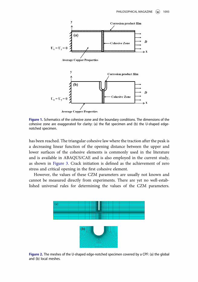
Two-dimensional finite element models of flat and U-shaped edge-notchedspecimens under tension were created. The specimen was loaded by a remotedisplacement. The cracking was modelled by the CZM in ABAQUS/CAE. Thecohesive elements were located in the middle of the model, schematicallyshown in Figure 1, with a very small initial thickness Tc = 10−5 mm. A 2Dplane strain model was constructed with the CPE4 and COH2D4 elements.The boundary conditions were as follows:
x = 0, Ux = Uy = 0 (1)
x = l0, Ux = D, Uy = 0 (2)
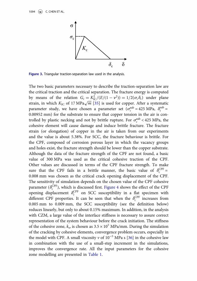
The global and local meshes of the U-shaped edge-notched specimen with aCPF are shown in Figure 2. When the notch and CPF dimensions change, themesh density around the notch is slightly altered to ensure consistency in thesize of the elements created around the notch, which indicates that themeshes created for the cases with different notch sizes will not be completelyidentical, but should yield similar levels of accuracy.
All the micromechanical damage processes that occur within the process zoneare embodied in the cohesive zone law. The CZM is characterised by the trac-tion-separation law [34]. The law can be expressed with the crack opening dis-placement δ and the critical traction σ. The cohesive element behaviour isassumed to be linear-elastic initially until the critical traction/displacement
1092 C. CHEN ET AL.
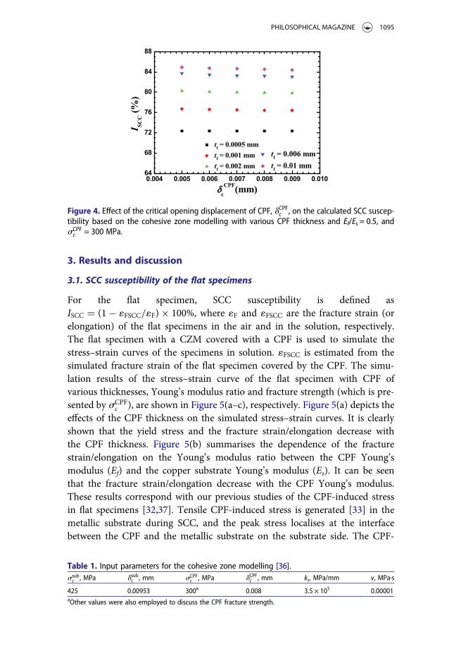
has been reached. The triangular cohesive law where the traction after the peak isa decreasing linear function of the opening distance between the upper andlower surfaces of the cohesive elements is commonly used in the literatureand is available in ABAQUS/CAE and is also employed in the current study,as shown in Figure 3. Crack initiation is defined as the achievement of zerostress and critical opening in the first cohesive element.
However, the values of these CZM parameters are usually not known andcannot be measured directly from experiments. There are yet no well-estab-lished universal rules for determining the values of the CZM parameters.
Figure 1. Schematics of the cohesive zone and the boundary conditions. The dimensions of thecohesive zone are exaggerated for clarity: (a) the flat specimen and (b) the U-shaped edge-notched specimen.
Figure 2. The meshes of the U-shaped edge-notched specimen covered by a CPF: (a) the globaland (b) local meshes.
PHILOSOPHICAL MAGAZINE 1093
The two basic parameters necessary to describe the traction-separation law arethe critical traction and the critical separation. The fracture energy is computedby means of the relation Gc = K2
IC/(E/(1− n2)) = 1/2(scdc) under planestrain, in which KIC of 17MPa
���
m√
[35] is used for copper. After a systematicparameter study, we have chosen a parameter set (ssub
c = 425 MPa, dsubc =0.00952 mm) for the substrate to ensure that copper tension in the air is con-trolled by plastic necking and not by brittle rupture. For ssub
c < 425 MPa, thecohesive element will cause damage and induce brittle fracture. The fracturestrain (or elongation) of copper in the air is taken from our experimentsand the value is about 5.38%. For SCC, the fracture behaviour is brittle. Forthe CPF, composed of corrosion porous layer in which the vacancy groupsand holes exist, the fracture strength should be lower than the copper substrate.Although the data of the fracture strength of the CPF are not found, a basicvalue of 300 MPa was used as the critical cohesive traction of the CPF.Other values are discussed in terms of the CPF fracture strength. To makesure that the CPF fails in a brittle manner, the basic value of dCPFc =0.008 mm was chosen as the critical crack opening displacement of the CPF.The sensitivity of simulation depends on the chosen value of the CPF cohesiveparameter (dCPFc ), which is discussed first. Figure 4 shows the effect of the CPFopening displacement dCPFc on SCC susceptibility in a flat specimen withdifferent CPF properties. It can be seen that when the dCPFc increases from0.005 mm to 0.009 mm, the SCC susceptibility (see the definition below)reduces linearly, but only to about 0.15% maximum. In addition, in the analysiswith CZM, a large value of the interface stiffness is necessary to assure correctrepresentation of the system behaviour before the crack initiation. The stiffnessof the cohesive zone, ks, is chosen as 3.5 × 10⁵ MPa/mm. During the simulationof the cracking by cohesive elements, convergence problem occurs, especially inthe model with CPF. A small viscosity v of 10−5 MPa s [36] in the cohesive lawin combination with the use of a small-step increment in the simulations,improves the convergence rate. All the input parameters for the cohesivezone modelling are presented in Table 1.
Figure 3. Triangular traction-separation law used in the analysis.
1094 C. CHEN ET AL.
3. Results and discussion
3.1. SCC susceptibility of the flat specimens
For the flat specimen, SCC susceptibility is defined asISCC = (1− 1FSCC/1F)× 100%, where 1F and 1FSCC are the fracture strain (orelongation) of the flat specimens in the air and in the solution, respectively.The flat specimen with a CZM covered with a CPF is used to simulate thestress–strain curves of the specimens in solution. 1FSCC is estimated from thesimulated fracture strain of the flat specimen covered by the CPF. The simu-lation results of the stress–strain curve of the flat specimen with CPF ofvarious thicknesses, Young’s modulus ratio and fracture strength (which is pre-sented by sCPF
c ), are shown in Figure 5(a–c), respectively. Figure 5(a) depicts theeffects of the CPF thickness on the simulated stress–strain curves. It is clearlyshown that the yield stress and the fracture strain/elongation decrease withthe CPF thickness. Figure 5(b) summarises the dependence of the fracturestrain/elongation on the Young’s modulus ratio between the CPF Young’smodulus (Ef) and the copper substrate Young’s modulus (Es). It can be seenthat the fracture strain/elongation decrease with the CPF Young’s modulus.These results correspond with our previous studies of the CPF-induced stressin flat specimens [32,37]. Tensile CPF-induced stress is generated [33] in themetallic substrate during SCC, and the peak stress localises at the interfacebetween the CPF and the metallic substrate on the substrate side. The CPF-
Figure 4. Effect of the critical opening displacement of CPF, dCPFc , on the calculated SCC suscep-tibility based on the cohesive zone modelling with various CPF thickness and Ef/Es= 0.5, andsCPFc = 300 MPa.
Table 1. Input parameters for the cohesive zone modelling [36].ssubc , MPa dsubc , mm sCPF
c , MPa dCPFc , mm ks, MPa/mm v, MPa·s
425 0.00953 300a 0.008 3.5 × 10⁵ 0.00001aOther values were also employed to discuss the CPF fracture strength.
PHILOSOPHICAL MAGAZINE 1095
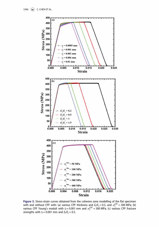
Figure 5. Stress-strain curves obtained from the cohesive zone modelling of the flat specimenwith and without CPF with: (a) various CPF thickness and Ef/Es= 0.5, and sCPF
c = 300 MPa; (b)various CPF Young’s moduli with tf= 0.001 mm and sCPF
c = 300 MPa; (c) various CPF fracturestrengths with tf= 0.001 mm and Ef/Es= 0.5.
1096 C. CHEN ET AL.
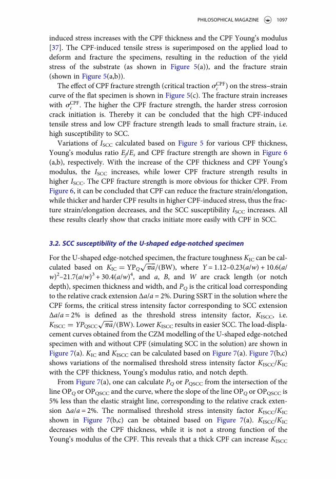
induced stress increases with the CPF thickness and the CPF Young’s modulus[37]. The CPF-induced tensile stress is superimposed on the applied load todeform and fracture the specimens, resulting in the reduction of the yieldstress of the substrate (as shown in Figure 5(a)), and the fracture strain(shown in Figure 5(a,b)).
The effect of CPF fracture strength (critical traction sCPFc ) on the stress–strain
curve of the flat specimen is shown in Figure 5(c). The fracture strain increaseswith sCPF
c . The higher the CPF fracture strength, the harder stress corrosioncrack initiation is. Thereby it can be concluded that the high CPF-inducedtensile stress and low CPF fracture strength leads to small fracture strain, i.e.high susceptibility to SCC.
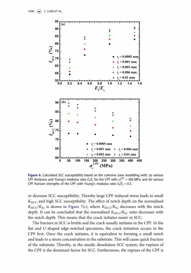
Variations of ISCC calculated based on Figure 5 for various CPF thickness,Young’s modulus ratio Ef/Es and CPF fracture strength are shown in Figure 6(a,b), respectively. With the increase of the CPF thickness and CPF Young’smodulus, the ISCC increases, while lower CPF fracture strength results inhigher ISCC. The CPF fracture strength is more obvious for thicker CPF. FromFigure 6, it can be concluded that CPF can reduce the fracture strain/elongation,while thicker and harder CPF results in higher CPF-induced stress, thus the frac-ture strain/elongation decreases, and the SCC susceptibility ISCC increases. Allthese results clearly show that cracks initiate more easily with CPF in SCC.
3.2. SCC susceptibility of the U-shaped edge-notched specimen
For the U-shaped edge-notched specimen, the fracture toughness KIC can be cal-culated based on KIC = YPQ
����
pa√
/(BW), where Y = 1.12–0.23(a/w) + 10.6(a/w)2–21.7(a/w)3 + 30.4(a/w)4, and a, B, and W are crack length (or notchdepth), specimen thickness and width, and PQ is the critical load correspondingto the relative crack extension Δa/a = 2%. During SSRT in the solution where theCPF forms, the critical stress intensity factor corresponding to SCC extensionΔa/a = 2% is defined as the threshold stress intensity factor, KISCC, i.e.KISCC = YPQSCC
����
pa√
/(BW). Lower KISCC results in easier SCC. The load-displa-cement curves obtained from the CZMmodelling of the U-shaped edge-notchedspecimen with and without CPF (simulating SCC in the solution) are shown inFigure 7(a). KIC and KISCC can be calculated based on Figure 7(a). Figure 7(b,c)shows variations of the normalised threshold stress intensity factor KISCC/KIC
with the CPF thickness, Young’s modulus ratio, and notch depth.From Figure 7(a), one can calculate PQ or PQSCC from the intersection of the
line OPQ or OPQSCC and the curve, where the slope of the line OPQ or OPQSCC is5% less than the elastic straight line, corresponding to the relative crack exten-sion Δa/a = 2%. The normalised threshold stress intensity factor KISCC/KIC
shown in Figure 7(b,c) can be obtained based on Figure 7(a). KISCC/KIC
decreases with the CPF thickness, while it is not a strong function of theYoung’s modulus of the CPF. This reveals that a thick CPF can increase KISCC
PHILOSOPHICAL MAGAZINE 1097
or decrease SCC susceptibility. Thereby large CPF-induced stress leads to smallKISCC and high SCC susceptibility. The effect of notch depth on the normalisedKISCC/KIC is shown in Figure 7(c), where KISCC/KIC decreases with the notchdepth. It can be concluded that the normalised KISCC/KIC ratio decreases withthe notch depth. This means that the crack initiates easier in SCC.
The fracture in SCC is brittle and the crack usually initiates in the CPF. In theflat and U-shaped edge-notched specimens, the crack initiation occurs in theCPF first. Once the crack initiates, it is equivalent to forming a small notchand leads to a stress concentration in the substrate. This will cause quick fractureof the substrate. Thereby, in the anodic dissolution SCC system, the rupture ofthe CPF is the dominant factor for SCC. Furthermore, the rupture of the CPF is
Figure 6. Calculated SCC susceptibility based on the cohesive zone modelling with: (a) variousCPF thickness and Young’s modulus ratio Ef/Es for the CPF with sCPF
c = 300 MPa, and (b) variousCPF fracture strengths of the CPF with Young’s modulus ratio Ef/Es = 0.5.
1098 C. CHEN ET AL.
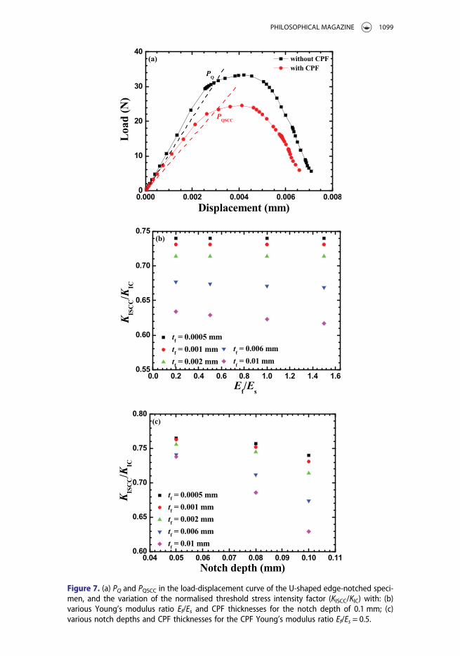
Figure 7. (a) PQ and PQSCC in the load-displacement curve of the U-shaped edge-notched speci-men, and the variation of the normalised threshold stress intensity factor (KISCC/KIC) with: (b)various Young’s modulus ratio Ef/Es and CPF thicknesses for the notch depth of 0.1 mm; (c)various notch depths and CPF thicknesses for the CPF Young’s modulus ratio Ef/Es = 0.5.
PHILOSOPHICAL MAGAZINE 1099
controlled by the CPF fracture strength. It can be concluded the CPF fracturestrength is significant for SCC.
4. Conclusions
A cohesive zone model is developed and applied to anodic dissolution stress cor-rosion cracking to simulate crack initiation in flat and U-shaped edge-notchedspecimens. Corrosion product film facilitates the stress corrosion crack initiationin the flat and U-shaped edge-notched specimens because of the existence of theCPF-induced stress. In the flat specimen, SCC susceptibility ISCC increases withthe decrease of the CPF fracture strength and the increase of the CPF thicknessand the CPF Young’s modulus. In the U-shaped edge-notched specimen, it isfound that the normalised threshold stress intensity factor (KISCC/KIC) decreaseswith the CPF thickness and the notch depth. Crack initiation occurs first in theCPF and then propagates into the substrate.
Disclosure statement
No potential conflict of interest was reported by the authors.
Funding
This work was supported by the National Natural Science Foundation of China [grantnumber 51571028]. AV acknowledges support from the National Science Foundation;Office of International Science and Engineering [grant number IRES 1358088].
ORCID
Cunguang Chen http://orcid.org/0000-0002-6525-228XAlex A. Volinsky http://orcid.org/0000-0002-8520-6248
References
[1] M. Kermani and J.C. Scully, The effect of strain-rate upon stress corrosion crack velocityin (-brass in ammoniacal solutions, Corros. Sci. 19 (1979), pp. 89–95. 97–110.
[2] A.J. Forty and P. Humble, The influence of surface tarnish on the stress corrosion of α-brass, Philos. Mag. 8 (1963), pp. 247–264.
[3] R.C. Newman, T. Shahrabi and K. Sieradzki, Film-induced cleavage of alpha-brass,Scripta Metall. 23 (1989), pp. 71–74.
[4] C. Zhang, Y.J. Su, L.J. Qiao and W.Y. Chu, Study on the role of tarnishing film in stress-corrosion cracking of brass in Mattsson’s solution, J. Mater. Res. 25 (2010), pp. 991–998.
[5] X.S. Du, Y.J. Su, C. Zhang, J.X. Li, L.J. Qiao, W.Y. Chu, W.G. Chen, Q.S. Zhang andD.X. Liu, Pre-strain enhances film rupture to promote SCC of brass in Mattsson’s sol-ution-A proposal for a film-rupture-induced SCC mechanism, Corros. Sci. 69 (2013),pp. 302–310.
1100 C. CHEN ET AL.
[6] M.G. Alvarez, P. Lapitz, S.A. Fernández and J.R. Galvele, Passivity breakdown and stresscorrosion cracking of α-brass in sodium nitrite solutions, Corros. Sci. 47 (2005), pp.1643–1652.
[7] X.S. Du, Y.J. Su, J.X. Li, L.J. Qiao and W.Y. Chu, Inhibitive effects and mechanism ofphosphates on the stress corrosion cracking of brass in ammonia solutions, Corros.Sci. 60 (2012), pp. 69–75.
[8] X.J. Guo, K.W. Gao, L.J. Qiao and W.Y. Chu, The correspondence between susceptibilityto SCC of brass and corrosion-induced tensile stress with various pH values, Corros. Sci.44 (2002), pp. 2367–2378.
[9] X.Z. Guo, K.W. Gao, W.Y. Chu and L.J. Qiao, Correlation between passive film-inducedstress and stress corrosion cracking of α-Ti in a methanol solution at various potentials,Mater. Sci. Eng. A. 346 (2003), pp. 1–7.
[10] X.Z. Guo, K.W. Gao, L.J. Qiao and W.Y. Chu, Stress corrosion cracking relation withdezincification layer-induced stress, Metall. Mater. Trans. A. 32 (2001), pp. 1309–1312.
[11] J.X. Li, W.Y. Chu, Y.B. Wang and L.J. Qiao, In situ TEM study of stress corrosion crack-ing of austenitic stainless steel, Corros. Sci. 45 (2003), pp. 1355–1365.
[12] X.S. Du, Y.J. Su, J.X. Li, L.J. Qiao and W.Y. Chu, Stress corrosion cracking of A537 steelin simulated marine environments, Corros. Sci. 65 (2012), pp. 278–287.
[13] R. Nishimura, Characterization and perspective of stress corrosion cracking of austeniticstainless steels (type 304 and type 316) in acid solutions using constant load method,Corros. Sci. 49 (2007), pp. 81–91.
[14] H.B. Chew, Cohesive zone laws for fatigue crack growth: Numerical field projection of themicromechanical damage process in an elasto-plastic medium, Int. J. Solids. Struct. 51(2014), pp. 1410–1420.
[15] X. Chen, X.M. Deng, M.A. Sutton and P. Zavattieri, An inverse analysis of cohesive zonemodel parameter values for ductile crack growth simulations, Int. J. Mech. Sci. 79 (2014),pp. 206–215.
[16] Y.J. Xu and H. Yuan, Applications of normal stress dominated cohesive zone models formixed-mode crack simulation based on extended finite element methods, Eng. Fract.Mech. 78 (2011), pp. 544–558.
[17] J.H. Lee, Y.F. Gao, K.E. Johanns and G.M. Pharr, Cohesive interface simulations ofindentation cracking as a fracture toughness measurement method for brittle materials,Acta Mater. 60 (2012), pp. 5448–5467.
[18] F. Moroni and A. Pirondi, A procedure for the simulation of fatigue crack growth inadhesively bonded joints based on a cohesive zone model and various mixed-modepropagation criteria, Eng. Fract. Mech. 89 (2012), pp. 129–138.
[19] B. Paliwal and M. Cherkaoui, An improved atomistic simulation based mixed-modecohesive zone law considering non-planar crack growth, Int. J. Solids. Struct. 50(2013), pp. 3346–3360.
[20] B. Yang, S. Mall and K. Ravi-Chandar, A cohesive zone model for fatigue crack growth inquasibrittle materials, Int. J. Solids. Struct. 38 (2001), pp. 3927–3944.
[21] S. Serebrinsky, E.A. Carter and M. Ortiz, A quantum-mechanically informed continuummodel of hydrogen embrittlement, J. Mech. Phys. Solids. 52 (2004), pp. 2403–2430.
[22] I. Scheider, M. Pfuff and W. Dietzel, Simulation of hydrogen assisted stress corrosioncracking using the cohesive model, Eng. Fract. Mech. 75 (2008), pp. 4283–4291.
[23] V. Olden, C. Thaulow, R. Johnsen and E. Østby, Cohesive zone modeling of hydrogen-induced stress cracking in 25% Cr duplex stainless steel, Scripta Mater. 57 (2007), pp.615–618.
PHILOSOPHICAL MAGAZINE 1101
[24] A. Alvaro, V. Olden and O.M. Akselsen, 3D cohesive modeling of hydrogen embrittle-ment in the heat affected zone of an X70 pipeline steel, Int. J. Hydrogen Energy. 38(2013), pp. 7539–7549.
[25] N.R. Raykar, S.K. Maiti and R.K. Singh Raman,Modelling of mode-I stable crack growthunder hydrogen assisted stress corrosion cracking, Eng. Fract. Mech. 78 (2011), pp.3153–3165.
[26] S. Guzmán, J.C. Gálvez and J.M. Sancho,Modelling of corrosion-induced cover crackingin reinforced concrete by an embedded cohesive crack finite element, Eng. Fract. Mech.93 (2012), pp. 92–107.
[27] H.Y. Yu, J.S. Olsen, A. Alvaro, V. Olden, J.Y. He and Z.L. Zhang, A uniform hydrogendegradation law for high strength steels, Eng. Fract. Mech. 157 (2016), pp. 56–71.
[28] M. Pezzotta, Z.L. Zhang, M. Jensen, T. Grande and M.-A. Einarsrud, Cohesive zonemodeling of grain boundary microcracking induced by thermal anisotropy in titaniumdiboride ceramics, Comp. Mater. Sci. 43 (2008), pp. 440–449.
[29] M. Pezzotta and Z.L. Zhang, Effect of thermal mismatch induced residual stresses ongrain boundary microcracking of titanium diboride ceramics, J. Mater. Sci. 45 (2010),pp. 382–391.
[30] M.S. Jensen, M. Pezzotta, Z.L. Zhang, M.-A. Einarsrud and T. Grande, Degradation ofTiB2 ceramics in liquid aluminum, J. Eur. Ceram. Soc. 28 (2008), pp. 3155–3164.
[31] X.B. Ren, Z.L. Zhang and B. Nyhus, Effect of residual stresses on the crack-tip constraintin a modified boundary layer model, Int. J. Solids Struct. 46 (2009), pp. 2629–2641.
[32] X.B. Ren, Z.L. Zhang and B. Nyhus, Effect of residual stresses on ductile crack growthresistance, Eng. Fract. Mech. 77 (2010), pp. 1325–1337.
[33] W.J. Yuan, Z.L. Zhang, Y.J. Su, L.J. Qiao and W.Y. Chu, A novel method to measure theresidual stress in a corrosion film formed on metallic substrates, Corros. Sci. 68 (2013),pp. 128–133.
[34] V. Tvergaard and J.W. Hutchinson, The relation between crack growth resistance andfracture process parameters in elastic-plastic solids, J. Mech. Phys. Solids 40 (1992),pp. 1377–1397.
[35] E.W. Qin, L. Lu, N.R. Tao, J. Tan and K. Lu, Enhanced fracture toughness and strengthin bulk nanocrystalline Cu with nanoscale twin bundles, Acta. Mater. 57 (2009), pp.6215–6225.
[36] Y.F. Gao and A.F. Brower, A simple technique for avoiding convergence problems infinite element simulations of crack nucleation and growth on cohesive interfaces,Modell. Simul. Mater. Sci. Eng. 12 (2004), pp. 453–463.
[37] W.W. Wang, Z.L. Zhang, X.C. Ren, Y.J. Guan and Y.J. Su, Corrosion product film-induced stress facilitates stress corrosion cracking, Sci. Rep. 5 (2015), pp. 10579.
1102 C. CHEN ET AL.


![Anodic dissolution behavior of zirconium in Bu NBr ... · acids and strong alkalis [21]. Thus, zirconium corrosion in non-aqueous solutions would be different from titanium and deserve](https://img.pdfslide.us/doc/110x75/5e51370660b2355520448e26/anodic-dissolution-behavior-of-zirconium-in-bu-nbr-acids-and-strong-alkalis.jpg)