Embed Size (px)
Citation preview

materials
Article
Stress Corrosion Behaviors of 316LN Stainless Steelin a Simulated PWR Primary Water Environment
Yong Huang 1, Weisong Wu 1, Shuo Cong 1, Guang Ran 1,*, Danxia Cen 2 and Ning Li 1,*1 College of Energy, Xiamen University, Xiamen 361102, China; [email protected] (Y.H.);
[email protected] (W.W.); [email protected] (S.C.)2 College of Chemistry and Chemical Engineering, Xiamen University, Xiamen 361102, China;
[email protected]* Correspondence: [email protected] (G.R.); [email protected] (N.L.); Tel./Fax: +86-592-2185-278 (G.R.)
Received: 25 July 2018; Accepted: 21 August 2018; Published: 23 August 2018�����������������
Abstract: The effect of the strain rate, experimental temperature, Zn content in the test solution,and prefilming time on the mechanical properties was investigated by a tensile test with a slow strainrate, at a chemical solution of 2.2 ppm Li and 1200 ppm B in a static autoclave with 8.2 MPa.The experimental parameters clearly affected the tensile properties. The surface morphology,fractograph, and cross-sectional microstructure were analyzed by scanning electron microscopyand transmission electron microscopy. The δ (elongation) and UTS (ultimate tensile strength) of thesamples tested in chemical solution were obviously lower than those of the samples tested under anitrogen atmosphere. However, in general, all samples showed a ductile fracture characteristic andan excellent tensile property in all experimental conditions. The δ and UTS were first increased withincreasing Zn content, and then decreased at both conditions of 9.26× 10⁻⁷/s and 4.63× 10⁻⁷/s strainrates. The difference values of tensile properties at different strain rates showed fluctuations withincreasing Zn content. The δ increased with both increasing experimental temperature and prefilmingtime. The UTS first decreased with increasing prefilming time and then increased. The Iscc (stresscorrosion cracking susceptibility) decreased with an increasing strain rate, experiment temperature,and prefilming time. Many particles with polyhedrons were formed on the sample surfaces, whichwas attributed to corrosion in a periodical location at the sample surface. The average length ofthe particles decreased with increasing Zn content, but increased with both increasing experimentaltemperatures and prefilming time. The corresponding mechanism is also discussed in this work.
Keywords: 316LN stainless steel; stress corrosion crack; tensile properties; nuclear materials
1. Introduction
316L stainless steel (316L SS) is widely used as a structural material in nuclear power plantsdue to its excellent mechanical properties, such as ductility, formability, toughness, and weldability,and its adequate irradiation and corrosion resistance [1–3]. However, in the in-service primary waterenvironment of a watercooled reactor, 316L SS will suffer not only high temperatures and high pressure,but also stress and water chemistry corrosion. Stress corrosion cracking (SCC) [4] is a serious problemthat induces the service failure of 316L SS, which is one of the greatest concerns in watercooled reactorsand has become a research hotspot. Some techniques retard SCC, including mechanical surfacestrengthening, environmental barriers or coatings, and chemical or electrochemical corrosion potentialcontrols such as zinc injections [5].
Zinc injections in a primary water environment are an effective and important method to retardthe initiation of stress corrosion cracking [6–8], which should be attributed to anode protection,mitigation of the general corrosion rate [3], the incorporation of zinc in spinel-type oxides [8–11],
Materials 2018, 11, 1509; doi:10.3390/ma11091509 www.mdpi.com/journal/materials
Materials 2018, 11, 1509 2 of 13
and the formation of ZnCr2O4 type inner layer oxides [12,13]. Meanwhile, zinc injections could reduceradioactivity accumulation [14–16]. The main investigations conducted so far include the following.(1) Microstructure analysis of the surface oxide film [5,17]; (2) investigation of the kinetic and transportbehaviors of surface oxidation [12]; (3) the zinc effect under different experimental conditions, includingdifferent water chemistry and loading conditions [3,18], nitrogen environments [19], irradiation [20],strain rates [21], and pH values [22]; (4) the Zn effect on the mechanical properties, such as stresscorrosion crack growth rates [3]; and (5) the synergistic effect of the zinc with other injected ionson oxide films, such as aluminum [23]. The investigation of the effect of zinc content on the SCCsusceptibility of Ni-base alloys [24], mill-annealed Alloy 600 [25], and Alloy 600 and 690 [26,27] bymeans of a slow strain rate tensile (SSRT) test was reported. Some interesting experimental results werefound. For example, a > 10 ppb zinc injection reduced the SCC susceptibility. However, few reportscould be found on 316LN SS. Moreover, there are still some questions associated with the mechanicalproperties and microstructural characteristics during the SSRT test process in chemical solutions withdifferent zinc contents that need to be further addressed and answered, such as the effect of a previouslyformed oxide film in the zinc solution, and the effect of a high zinc content on the mechanical properties,the corresponding corrosion behavior, and the mechanism. The experimental temperature also affectsthe tensile properties, however there is not a universal law for this. For example, Jones [28] reportedthe tensile properties varied with experimental temperature. However, Brnic [29] reported that whenthe experimental temperature was increased from 250 ◦C to 350 ◦C, the mechanical properties of 316LSS almost remained constant. Wang [30] found that the corrosion rate of Alloy 690 in a primary waterenvironment reached its maximum at 250 ◦C. In addition, Lee [31] developed a comprehensive SCCgrowth rate model and De Meo [32] reported a numerical multiphysics peridynamic framework forthe modeling of adsorbed-SCC based on the adsorption induced decohesion mechanism.
Therefore, in the present work, the effect of the Zn content in the test solution, experimentaltemperature, strain rate, and prefilming time on the mechanical properties and microstructureduring the SSRT test process was fully investigated. The surface morphology, fractograph,and cross-sectional microstructure after the SSRT test were observed and analyzed in detail by scanningelectron microscopy (SEM) and transmission electron microscopy (TEM), in order to understand thecorresponding mechanisms.
2. Experimental Methods
316LN SS with Fe-16.96Cr-13.19Ni-2.38Mo-1.21Mn (wt %) chemical composition, which camefrom the components of a Pressurized Water Reactor (PWR) in China, was used in the present work.The detailed chemical composition is listed in Table 1.
Table 1. Chemical composition of 316LN SS used in the present work (mass fraction, %).
Element C Si Mn P S Cr Ni Mo N Co Fe
Content 0.019 0.22 1.21 0.014 0.002 16.96 13.19 2.38 0.14 0.012 Bal.
The tensile samples with an 18 mm gauge length were prepared by the wire-electrode cuttingmethod from the as-received bulk materials. The sketch of the samples for the SSRT test is shownin Figure 1. All samples first underwent grinding by a series of SiC sandpapers from #320 to #5000grids, and were then polished by a series of diamond suspensions from 3 to 0.1 µm. Finally, the samplesurface was ultrasonically cleaned in an ethanol solution and then dried in air.
The SSRT test was performed in a static autoclave (CFS-50, Bairoe, Shanghai, China) at a hightemperature and high pressure. The volume and material of the static autoclave were 4 L and 316LSS, respectively. Before the SSRT test, the autoclave interior was washed with deionized water andthen with the test solution. The process was repeated three times. After that, 3.5 L of test solution was

Materials 2018, 11, 1509 3 of 13
poured into the autoclave and then heated to 104 ◦C. Before the samples were loaded, all valves wereclosed. The test solution was finally heated to a designed experimental temperature, such as 300 ◦C.
The experimental pressure was 8.2 ± 0.1 MPa. The deionized water, analytical-grade lithiumhydroxide (LiOH·H2O), and boric acid (H3BO3) were proportionally mixed to form the test solutionwith 2.2 ppm Li and 1200 ppm B. A summary of the main experimental parameters is listed in Table 2.The main tasks of the present work were to investigate the effect of the strain rate, experimentaltemperature, Zn content in the test solution, and prefilming time on the tensile properties. The zincacetate (Zn(CH3COO)2·H2O) was added into the test solution to form different Zn concentrations.Four groups of experiments were designed and carried out: (1) The first group of samples weretested with a Zn content from 0 to 100 ppb at a constant strain rate of 4.63 × 10⁻⁷/s and at 300 ◦C.(2) The second group of samples were tested with a Zn content from 0 to 100 ppb at a constant strainrate of 9.26 × 10⁻⁷/s and at 300 ◦C. (3) The third group of samples were tested at an experimentaltemperature from 250 to 330 ◦C at a 9.26 × 10⁻⁷/s strain rate and a constant chemical solution of75 ppb Zn, 2.2 ppm Li, and 1200 ppm B. (4) The fourth group of samples were tested with a prefilmingtime from 0 to 600 h at 300 ◦C, a 4.63 × 10⁻⁷/s strain rate, and a chemical solution of 75 ppb Zn,2.2 ppm Li, and 1200 ppm B. In addition, the sample #1 was tested under a nitrogen atmosphere at a9.26 × 10−7/s strain rate and at 300 ◦C.
Materials 2018, 11, x FOR PEER REVIEW 3 of 13
The experimental pressure was 8.2 ± 0.1 MPa. The deionized water, analytical-grade lithium hydroxide (LiOH·H2O), and boric acid (H3BO3) were proportionally mixed to form the test solution with 2.2 ppm Li and 1200 ppm B. A summary of the main experimental parameters is listed in Table 2. The main tasks of the present work were to investigate the effect of the strain rate, experimental temperature, Zn content in the test solution, and prefilming time on the tensile properties. The zinc acetate (Zn(CH3COO)2·H2O) was added into the test solution to form different Zn concentrations. Four groups of experiments were designed and carried out: (1) The first group of samples were tested with a Zn content from 0 to 100 ppb at a constant strain rate of 4.63 × 10⁻⁷/s and at 300 °C. (2) The second group of samples were tested with a Zn content from 0 to 100 ppb at a constant strain rate of 9.26 × 10⁻⁷/s and at 300 °C. (3) The third group of samples were tested at an experimental temperature from 250 to 330 °C at a 9.26 × 10⁻⁷/s strain rate and a constant chemical solution of 75 ppb Zn, 2.2 ppm Li, and 1200 ppm B. (4) The fourth group of samples were tested with a prefilming time from 0 to 600 h at 300 °C, a 4.63 × 10⁻⁷/s strain rate, and a chemical solution of 75 ppb Zn, 2.2 ppm Li, and 1200 ppm B. In addition, the sample #1 was tested under a nitrogen atmosphere at a 9.26 × 10⁻⁷/s strain rate and at 300 °C.
Figure 1. The sketch of samples used in the slow strain rate tensile (SSRT) test (Unit: mm).
Table 2. Main experimental parameters during the slow strain rate tensile (SSRT) test.
Samples #1 * #2 #3 #4 #5 #6 #7 #8 #9 #10 #11 #12 #13 Zn content (ppb) 0 0 50 75 100 0 50 75 100 75 75 75 75
Experiment temperature 300 °C 250 330 300 °C
Strain rate 9.26 × 10⁻⁷/s 4.63 × 10⁻⁷/s 9.26 × 10⁻⁷/s 4.63 × 10⁻⁷/s Prefilming time, h 0 0 0 0 0 0 0 0 0 0 0 300 600
* #1 sample was tested under a nitrogen atmosphere.
The surface topography and fracture morphology of the tested samples were observed by SEM on a CARL ZEISS SUPRA 55 GEMINI instrument (ZEISS, Heidenheim, Germany). In order to observe the characteristic microstructure on the sample surface, the cross-sectional TEM samples from the corrosion layer to the alloy matrix were prepared by focused ion beam (FIB) technology, covering a region that extended to areas far away from the sample surface in a field emission scanning electron microscope (FESEM)/FIB dual-beam system. The TEM observations were carried out in a JEM 2100 TEM instrument (JEOL Company, Tokyo, Japan).
3. Results and Discussion
The stress–strain curves of the 316LN stainless steel tested at the conditions of 0.001 mm/min tensile rate, 0.0005 mm/min tensile rate, different temperature, and different prefilm time are shown in Figure 2a–d, respectively. It can be seen that the stress–strain curves of all samples show the same trend. The mechanical properties of sample #1 tested in a nitrogen environment is the best. The tensile properties of 316LN SS after the SSRT test are listed in Table 3. The shape of the stress–strain curves is similar for all samples tested in different experimental conditions, showing a ductile fracture characteristic. The relationships between the tensile properties and experimental parameters such as
Figure 1. The sketch of samples used in the slow strain rate tensile (SSRT) test (Unit: mm).
Table 2. Main experimental parameters during the slow strain rate tensile (SSRT) test.
Samples #1 * #2 #3 #4 #5 #6 #7 #8 #9 #10 #11 #12 #13
Zn content (ppb) 0 0 50 75 100 0 50 75 100 75 75 75 75Experimenttemperature 300 ◦C 250 330 300 ◦C
Strain rate 9.26 × 10⁻⁷/s 4.63 × 10⁻⁷/s 9.26 × 10⁻⁷/s 4.63 × 10⁻⁷/sPrefilming time, h 0 0 0 0 0 0 0 0 0 0 0 300 600
* #1 sample was tested under a nitrogen atmosphere.
The surface topography and fracture morphology of the tested samples were observed by SEMon a CARL ZEISS SUPRA 55 GEMINI instrument (ZEISS, Heidenheim, Germany). In order to observethe characteristic microstructure on the sample surface, the cross-sectional TEM samples from thecorrosion layer to the alloy matrix were prepared by focused ion beam (FIB) technology, covering aregion that extended to areas far away from the sample surface in a field emission scanning electronmicroscope (FESEM)/FIB dual-beam system. The TEM observations were carried out in a JEM 2100TEM instrument (JEOL Company, Tokyo, Japan).
3. Results and Discussion
The stress–strain curves of the 316LN stainless steel tested at the conditions of 0.001 mm/mintensile rate, 0.0005 mm/min tensile rate, different temperature, and different prefilm time are shownin Figure 2a–d, respectively. It can be seen that the stress–strain curves of all samples show thesame trend. The mechanical properties of sample #1 tested in a nitrogen environment is the best.

Materials 2018, 11, 1509 4 of 13
The tensile properties of 316LN SS after the SSRT test are listed in Table 3. The shape of the stress–straincurves is similar for all samples tested in different experimental conditions, showing a ductile fracturecharacteristic. The relationships between the tensile properties and experimental parameters suchas the strain rate, experimental temperature, Zn content in the test solution, and prefilming time areshown in Figure 3. The results indicate that the experimental parameters obviously affect the tensileproperties. The δ (strain under maximum load) and UTS (ultimate tensile strength) of the samplestested under a nitrogen atmosphere are obviously larger than those of the samples tested in a chemicalsolution, as shown in Figure 3a, which indicates that chemical corrosion accelerates sample fractureand reduces the tensile properties. However, in general, the samples show excellent tensile propertiesunder all experimental conditions. The δ and UTS are over 43% and 464.5 MPa, respectively.
Materials 2018, 11, x FOR PEER REVIEW 4 of 13
the strain rate, experimental temperature, Zn content in the test solution, and prefilming time are shown in Figure 3. The results indicate that the experimental parameters obviously affect the tensile properties. The δ (strain under maximum load) and UTS (ultimate tensile strength) of the samples tested under a nitrogen atmosphere are obviously larger than those of the samples tested in a chemical solution, as shown in Figure 3a, which indicates that chemical corrosion accelerates sample fracture and reduces the tensile properties. However, in general, the samples show excellent tensile properties under all experimental conditions. The δ and UTS are over 43% and 464.5 MPa, respectively.
Figure 2. Stress–strain curves of the 316LN stainless steel tested at the conditions of (a) 0.001 mm/min tensile rate; (b) 0.0005 mm/min tensile rate; (c) different temperature; and (d) different prefilm time.
Table 3. Tensile properties of 316LN SS after the SSRT test.
Sample #1 #2 #3 #4 #5 #6 #7 #8 #9 #10 #11 #12 #13 UTS, MPa
507.3 ± 5.48
492.7 ± 5.32
495.2 ± 5.35
491 ± 5.30
484.7 ± 5.23
480.5 ± 5.19
464.6 ± 5.01
487.7 ± 5.26
475.3 ± 5.13
477.1 ± 5.15
496.1 ± 5.35
483.3 ± 5.22
496.9 ± 5.36
δ, % 55.0 ± 0.05 50.5 ± 0.05 52.8 ± 0.05 52.4 ± 0.05 51.7 ± 0.05 45.1 ± 0.05 44.3 ± 0.05 46.7 ± 0.05 43.4 ± 0.05 47.0 ± 0.05 53.3 ± 0.05 49.4 ± 0.05 54 ± 0.05
Iscc, % / 8.2 4.0 4.7 6.0 18.0 19.5 15.1 21.1 14.5 3.1 10.2 1.8
With both a 9.26 × 10⁻⁷/s (0.001 mm/min) and 4.63 × 10⁻⁷/s (0.0005 mm/min) strain rate, the δ and UTS first increased with increasing Zn content, and then decreased. The δ and UTS are the largest in the chemical solution with 50 ppb Zn. For example, at a strain rate of 9.26 × 10⁻⁷/s, the δ and UTS are 52.8% and 495.2 MPa, respectively. The reason should be attributed to the zinc injection suppressing the hydrogen reduction reaction, forming a stable oxide film composed of a zinc–chromium phase which decreases the SCC susceptibility. As shown in Figure 3a, at the range of 0 to 50 ppb Zn in the chemical solution, both UTS and δ increase with increasing Zn content. The Zn oxides are cationic superchemically proportioned oxides. Zn atoms tend to occupy the tetrahedral position of AB2O4. These oxides have a normal spinel structure. With the substitution of Fe2+, Ni2+, or Co2+ with Zn2+ and
Figure 2. Stress–strain curves of the 316LN stainless steel tested at the conditions of (a) 0.001 mm/mintensile rate; (b) 0.0005 mm/min tensile rate; (c) different temperature; and (d) different prefilm time.
Table 3. Tensile properties of 316LN SS after the SSRT test.
Sample #1 #2 #3 #4 #5 #6 #7 #8 #9 #10 #11 #12 #13
UTS,MPa
507.3± 5.48
492.7± 5.32
495.2± 5.35
491 ±5.30
484.7± 5.23
480.5± 5.19
464.6± 5.01
487.7± 5.26
475.3± 5.13
477.1± 5.15
496.1± 5.35
483.3± 5.22
496.9± 5.36
δ, % 55.0 ±0.05
50.5 ±0.05
52.8 ±0.05
52.4 ±0.05
51.7 ±0.05
45.1 ±0.05
44.3 ±0.05
46.7 ±0.05
43.4 ±0.05
47.0 ±0.05
53.3 ±0.05
49.4 ±0.05
54 ±0.05
Iscc, % / 8.2 4.0 4.7 6.0 18.0 19.5 15.1 21.1 14.5 3.1 10.2 1.8
With both a 9.26 × 10⁻⁷/s (0.001 mm/min) and 4.63 × 10⁻⁷/s (0.0005 mm/min) strain rate, the δ
and UTS first increased with increasing Zn content, and then decreased. The δ and UTS are the largestin the chemical solution with 50 ppb Zn. For example, at a strain rate of 9.26 × 10⁻⁷/s, the δ and UTSare 52.8% and 495.2 MPa, respectively. The reason should be attributed to the zinc injection suppressing

Materials 2018, 11, 1509 5 of 13
the hydrogen reduction reaction, forming a stable oxide film composed of a zinc–chromium phasewhich decreases the SCC susceptibility. As shown in Figure 3a, at the range of 0 to 50 ppb Zn in thechemical solution, both UTS and δ increase with increasing Zn content. The Zn oxides are cationicsuperchemically proportioned oxides. Zn atoms tend to occupy the tetrahedral position of AB2O4.These oxides have a normal spinel structure. With the substitution of Fe2+, Ni2+, or Co2+ with Zn2+ andthe embedding of Zn2+ in cation vacancies, a more stable structure of ZnCr2O4 spinel is formed [33].The newly formed compact oxide film has less cation vacancies and low solubility in water. It canprevent the oxidation of the metal atoms in the matrix and their transmigration through the oxidefilm. Therefore, the growth rate of the oxide film is reduced. The Zn content in the oxide film and thesolution follows the thermodynamic equilibrium. The change of the oxide film after zinc injection isas follows:
Zn2+(aq) + FeCr2O4(s)↔ Fe2+(aq) + ZnCr2O4(s)
Zn2+(aq) + NiCr2O4(s)↔ Ni2+(aq) + ZnCr2O4(s)
Zn2+(aq) + Fe3O4(s)↔ Fe2+(aq) + ZnFe2O4(s)
The Gibbs free energy (∆G) of ZnCr2O4 and ZnFe2O4 is−1480.415 and−1122.138 kJ/mol, respectively,while the ∆G of FeCr2O4, NiCr2O4, and Fe3O4 is−1321.836,−1398.044, and−1076.294 kJ/mol, respectively.Therefore, after the substitution of Fe2+, Ni2+, or Co2+ with Zn2+, ∆G is decreased. This means that thethermodynamic stability of the newly formed oxide film is higher [34]. Thus, the Zn injection can inhibitcrack initiation and growth, increasing the mechanical property. However, beyond a certain amount of Zninjection in the chemical solution, the δ and UTS are decreased with increasing Zn content. The reasonfor this is that the thickness of the oxide film decreases rapidly as the concentration of the Zn injection isincreased. Meanwhile, the crack growth rate decreases slowly. If the oxide film is too thin, it may break upearlier and the corrosion will be accelerated.
The δ and UTS are increased with increasing experimental temperatures, as shown in Figure 3b.The UTS is 477.1 MPa, 491 MPa, and 496.1 MPa for temperatures of 250 ◦C, 300 ◦C, and 330 ◦C,respectively. The increment of UTS is 19 MPa when the temperature is increased from 250 ◦C to 330 ◦C.The δ is 47.0%, 52.4%, and 53.3% for temperatures of 250 ◦C, 300 ◦C, and 330 ◦C, respectively. It canbe seen that the tensile properties are optimal at 330 ◦C. However, Brnic [29] reported that when theexperimental temperature was increased from 250 ◦C to 350 ◦C, the mechanical properties of 316L SSalmost remained constant. Wang [30] found that the corrosion rate of Alloy 690 in a primary waterenvironment reached its maximum at 250 ◦C. It is known that the growth kinetics of oxide film arecontrolled by ion diffusion from the chemical solution to the oxidation film. The dynamic strain aging(DSA) theory proposed by Katada [35] and Atkinson [36] can be used to explain these results, in whichthe effect of the Zn injection on an established surface could be used to explain the environmentallysensitive fracture of the material. When the strain rate is very low, DSA more easily occurs in the rangeof 100 to 350 ◦C.
Previous corrosion, before the SSRT test, evidently enhances the elongation, as shown in Figure 3c.The elongation is 46.7%, 49.4%, and 54% at a prefilming time of 0 h, 300 h, and 600 h, respectively.The elongation increases by about 7.3% when the prefilming time is increased from 0 h to 600 h.However, the UTS is first decreased with increasing prefilming time, and then increased. The UTSis about 496.9 MPa after previous corrosion for 600 h. In all, previous corrosion improves the tensileproperties. Prefilming can increase the specific gravity of Cr oxide and Zn oxide in the surface oxidefilm, and can inhibit the initiation and propagation of surface cracks, which can improve the mechanicalproperties of the material and reduce the sensitivity of stress corrosion. The mechanical propertiesof 316LN SS with prefilming for 600 h are obviously greater than those without prefilming, and arethe opposite for the susceptibility to stress corrosion. Liu [17] found that the initial water chemistryplayed a key role for the characteristics of surface oxide films. The films become much more compactwith increasing exposure time in the Zn-injection solution.

Materials 2018, 11, 1509 6 of 13
Materials 2018, 11, x FOR PEER REVIEW 6 of 13
Figure 3. (a) Tensile properties vs. Zn content in the chemical solution; (b) tensile properties vs. experimental temperature; (c) tensile properties vs. prefilming time; and (d) reduced values of tensile properties when the strain rate decreases from 9.26 × 10⁻⁷/s to 4.63 × 10⁻⁷/s with different Zn content in chemical solution.
Figure 3d shows the relationship between the difference values of the tensile properties at the strain rate of 9.26 × 10⁻⁷/s and 4.63 × 10⁻⁷/s, and Zn content in the chemical solution. The difference values of the tensile properties decrease with increasing Zn content, then increase and finally decrease again. The UTS and δ at a strain rate of 9.26 × 10⁻⁷/s are larger than those at a strain rate of 4.63 × 10⁻⁷/s. The reason is due to the chemical corrosion being much more serious, and decreasing the tensile properties at a strain rate of 4.63 × 10⁻⁷/s. The lower the strain rate is, the longer the corrosion time will be.
Iscc (stress corrosion cracking susceptibility, Iscc), calculated according to Equation (1), can be used to evaluate the SCC susceptibility of 316LN SS [37]. The larger the Iscc value is, the more sensitive to SCC it will be. The results show that previous corrosion in a chemical solution with 75 ppb Zn content clearly reduces the SCC susceptibility, as shown in Figure 4a. The Iscc is 15.1, 10.2, and 1.8 at a prefilming time of 0 h, 300 h, and 600 h, respectively. The Iscc decreases with increasing experimental temperatures, as shown in Figure 4b. The Iscc is 14.5, 4.7, and 3.1 for temperatures of 250 °C, 300 °C, and 330 °C, respectively. However, as shown in Figure 4c, the lower the strain rate is, the larger the Iscc value will be. 𝐼 = 1 − 𝛿𝛿 (1)
where, 𝛿 and 𝛿 are the elongation after the SSRT test in a nitrogen atmosphere and under special experimental conditions, respectively.
Figure 3. (a) Tensile properties vs. Zn content in the chemical solution; (b) tensile properties vs.experimental temperature; (c) tensile properties vs. prefilming time; and (d) reduced values of tensileproperties when the strain rate decreases from 9.26× 10⁻⁷/s to 4.63× 10⁻⁷/s with different Zn contentin chemical solution.
Figure 3d shows the relationship between the difference values of the tensile properties at thestrain rate of 9.26 × 10⁻⁷/s and 4.63 × 10⁻⁷/s, and Zn content in the chemical solution. The differencevalues of the tensile properties decrease with increasing Zn content, then increase and finally decreaseagain. The UTS and δ at a strain rate of 9.26 × 10⁻⁷/s are larger than those at a strain rate of4.63 × 10−7/s. The reason is due to the chemical corrosion being much more serious, and decreasingthe tensile properties at a strain rate of 4.63 × 10⁻⁷/s. The lower the strain rate is, the longer thecorrosion time will be.
Iscc (stress corrosion cracking susceptibility, Iscc), calculated according to Equation (1), can be usedto evaluate the SCC susceptibility of 316LN SS [37]. The larger the Iscc value is, the more sensitiveto SCC it will be. The results show that previous corrosion in a chemical solution with 75 ppb Zncontent clearly reduces the SCC susceptibility, as shown in Figure 4a. The Iscc is 15.1, 10.2, and 1.8 at aprefilming time of 0 h, 300 h, and 600 h, respectively. The Iscc decreases with increasing experimentaltemperatures, as shown in Figure 4b. The Iscc is 14.5, 4.7, and 3.1 for temperatures of 250 ◦C, 300 ◦C,and 330 ◦C, respectively. However, as shown in Figure 4c, the lower the strain rate is, the larger the Iscc
value will be.
Iscc = 1−δx
f
δN2f
(1)
where, δN2f and δx
f are the elongation after the SSRT test in a nitrogen atmosphere and under specialexperimental conditions, respectively.

Materials 2018, 11, 1509 7 of 13
Materials 2018, 11, x FOR PEER REVIEW 7 of 13
Figure 4. (a) Iscc vs. prefilming time; (b) Iscc vs. the experimental temperature; and (c) Iscc vs. Zn content in the chemical solution.
Figure 5 presents SEM images showing the surface morphologies of the samples after the SSRT test at four kinds of experimental conditions. Some characteristic particles with polyhedrons are formed on the samples’ surfaces. The formed particles should be spinel oxides, such as FeCr2O4, ZnFe2O4, and ZnCr2O4. It is known that Fe3O4 and FeCr2O4 are common corrosion products of stainless steel [38,39]. With the addition of Zn in the chemical solution, ZnFe2O4 and ZnCr2O4 could be formed in the oxide film [17,40].
Figure 5. SEM images showing the surface morphologies of (a) #12 sample; (b) #7 sample; (c) #8 sample; and (d) #9 sample after the SSRT test.
Figure 4. (a) Iscc vs. prefilming time; (b) Iscc vs. the experimental temperature; and (c) Iscc vs. Zncontent in the chemical solution.
Figure 5 presents SEM images showing the surface morphologies of the samples after the SSRTtest at four kinds of experimental conditions. Some characteristic particles with polyhedrons areformed on the samples’ surfaces. The formed particles should be spinel oxides, such as FeCr2O4,ZnFe2O4, and ZnCr2O4. It is known that Fe3O4 and FeCr2O4 are common corrosion products ofstainless steel [38,39]. With the addition of Zn in the chemical solution, ZnFe2O4 and ZnCr2O4 couldbe formed in the oxide film [17,40].
Materials 2018, 11, x FOR PEER REVIEW 7 of 13
Figure 4. (a) Iscc vs. prefilming time; (b) Iscc vs. the experimental temperature; and (c) Iscc vs. Zn content in the chemical solution.
Figure 5 presents SEM images showing the surface morphologies of the samples after the SSRT test at four kinds of experimental conditions. Some characteristic particles with polyhedrons are formed on the samples’ surfaces. The formed particles should be spinel oxides, such as FeCr2O4, ZnFe2O4, and ZnCr2O4. It is known that Fe3O4 and FeCr2O4 are common corrosion products of stainless steel [38,39]. With the addition of Zn in the chemical solution, ZnFe2O4 and ZnCr2O4 could be formed in the oxide film [17,40].
Figure 5. SEM images showing the surface morphologies of (a) #12 sample; (b) #7 sample; (c) #8 sample; and (d) #9 sample after the SSRT test. Figure 5. SEM images showing the surface morphologies of (a) #12 sample; (b) #7 sample; (c) #8 sample;
and (d) #9 sample after the SSRT test.

Materials 2018, 11, 1509 8 of 13
In order to investigate the variation tendency of the average length of the formed particleswith experiment parameters, the species of the formed particles on the sample surface do not bedistinguished. The results of the statistical analysis of the average length of the formed particles onthe sample surface are shown in Figure 6. Quantitative analysis of particle size was conducted usinga Nano Measure software (Nano Measure 1.2.5, Shanghai, China). The counting numbers for onesample exceeded 100. The error bar was less than 1%. The results show that the average length ofthe formed particles decreased with increasing Zn content at a 4.63 × 10⁻⁷/s strain rate. The averagelength is about 0.89 µm and 0.44 µm with chemical solutions of 0 ppb Zn and 100 ppb Zn, respectively.The average length increased with increasing experiment temperatures, which can be attributed to thehigh chemical activity at a high experiment temperature, and the corresponding high corrosion rateand high migration rate of matrix atoms. The average length is about 0.5 µm, 0.69 µm, and 0.91 µm at250 ◦C, 300 ◦C, and 330 ◦C, respectively. It can be seen that the average length is increased by about twotimes when the experiment temperature is increased from 250 ◦C to 330 ◦C. The longer the previouscorrosion time was, the larger the average length of the particles will be. The average length is up to0.85 µm with previous corrosion of 600 h, which is about 1.55 times that with nonprevious corrosion.
Materials 2018, 11, x FOR PEER REVIEW 8 of 13
In order to investigate the variation tendency of the average length of the formed particles with experiment parameters, the species of the formed particles on the sample surface do not be distinguished. The results of the statistical analysis of the average length of the formed particles on the sample surface are shown in Figure 6. Quantitative analysis of particle size was conducted using a Nano Measure software (Nano Measure 1.2.5, Shanghai, China). The counting numbers for one sample exceeded 100. The error bar was less than 1%. The results show that the average length of the formed particles decreased with increasing Zn content at a 4.63 × 10⁻⁷/s strain rate. The average length is about 0.89 μm and 0.44 μm with chemical solutions of 0 ppb Zn and 100 ppb Zn, respectively. The average length increased with increasing experiment temperatures, which can be attributed to the high chemical activity at a high experiment temperature, and the corresponding high corrosion rate and high migration rate of matrix atoms. The average length is about 0.5 μm, 0.69 μm, and 0.91 μm at 250 °C, 300 °C, and 330 °C, respectively. It can be seen that the average length is increased by about two times when the experiment temperature is increased from 250 °C to 330 °C. The longer the previous corrosion time was, the larger the average length of the particles will be. The average length is up to 0.85 μm with previous corrosion of 600 h, which is about 1.55 times that with nonprevious corrosion.
Figure 6. Statistical analysis results of the particles on the sample surface: (a) Length vs. Zn content; (b) length vs. experiment temperature; and (c) length vs. prefilming time.
The SEM fractographs of the samples tested under the experimental condition of previously corrosion for 300 h, with the experiment solution of 75 ppb Zn, 2.2 ppm Li, and 1200 ppm B are shown in Figure 7. In general, the studied alloy shows a clear ductile fracture nature. The crack initiates from the sample surface, as denoted in Figure 7a, and the secondary cracks are also seen in the fracture surface. According to the morphology, the fracture surface has a pseudo-cleavage feature and plastic tearing feature (a large number of dimples as shown in Figure 7b) in the last stage of crack growth at a high magnification. The fracture feature and fractograph are similar for the samples tested under all experimental conditions.
Figure 6. Statistical analysis results of the particles on the sample surface: (a) Length vs. Zn content;(b) length vs. experiment temperature; and (c) length vs. prefilming time.
The SEM fractographs of the samples tested under the experimental condition of previouslycorrosion for 300 h, with the experiment solution of 75 ppb Zn, 2.2 ppm Li, and 1200 ppm B are shownin Figure 7. In general, the studied alloy shows a clear ductile fracture nature. The crack initiates fromthe sample surface, as denoted in Figure 7a, and the secondary cracks are also seen in the fracturesurface. According to the morphology, the fracture surface has a pseudo-cleavage feature and plastictearing feature (a large number of dimples as shown in Figure 7b) in the last stage of crack growth at ahigh magnification. The fracture feature and fractograph are similar for the samples tested under allexperimental conditions.

Materials 2018, 11, 1509 9 of 13
Materials 2018, 11, x FOR PEER REVIEW 9 of 13
Figure 7. SEM images showing the fracture structure: (a) Crack initiation area; (b) dimples.
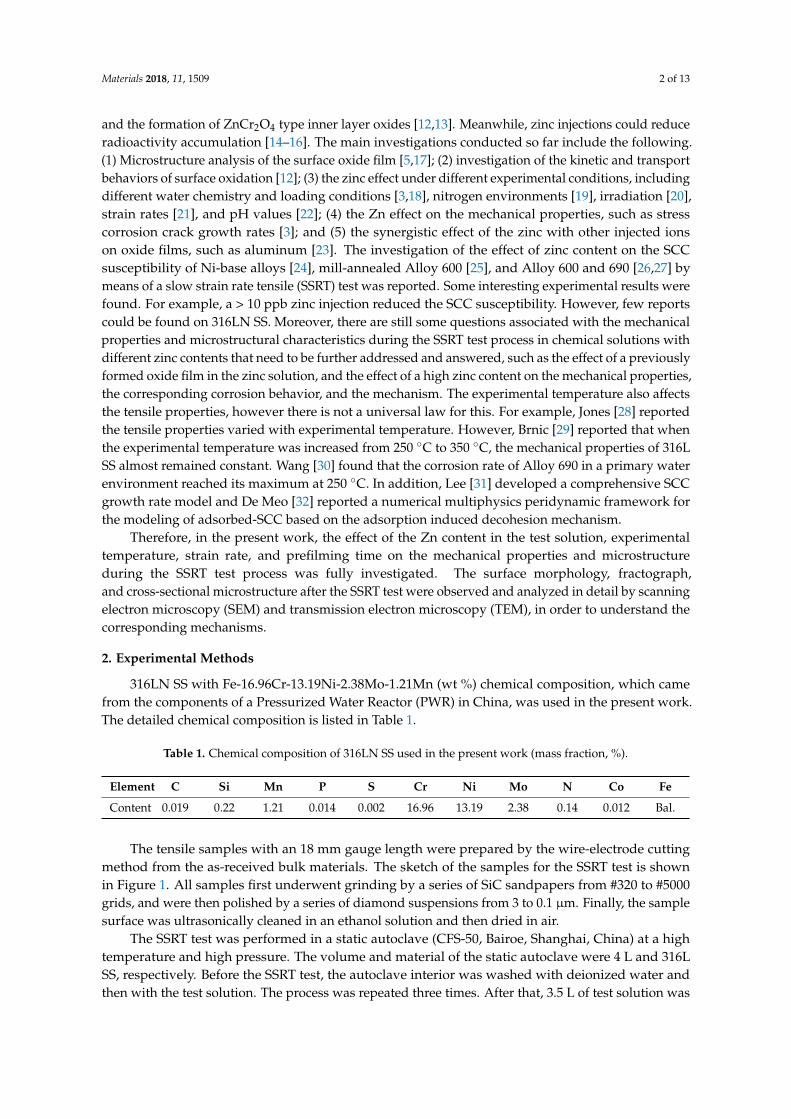
In order to observe the characteristic microstructure and analyze the formation mechanism of the particles on the sample surface, the TEM sample, which was perpendicular to the surface of tensile sample #12, was prepared by in situ focused ion beam. The Pt coating as indicated in Figure 8a was used to protect the microstructure during TEM preparation. The cross-sectional bright field TEM image is shown in Figure 8a. Grains with a rectangular shape, as denoted by the letter ‘B’, can be observed at the sample subsurface. An oxidation corrosion layer covers the rectangular grains. The inserted image located at the left-bottom corner of Figure 8a is the corresponding selected area electron diffraction pattern at location ‘B’, which shows the austenite crystal structure. The energy dispersive spectrum (EDS) analysis results of locations ‘A’, ‘B’, and ‘C’ in Figure 8a are shown in Figure 8b–d, respectively. The semiquantitative results of the analysis elements are shown in Table 4. It can be seen that the content of elemental O and C in the location ‘C’ is much higher than in the locations ‘A’ and ‘B’. The opposite is true for elemental Fe and Cr. However, the content of elemental Ni is similar in all locations. In addition, compared with test results in location ‘A’, the elemental content in location ‘B’ is the same if the measurement error by the EDS method is taken into account. Therefore, location ‘B’ also belongs to the alloy matrix. Similar results are obtained from several other locations. In fact, the content of elemental Zn is very low, and thus it is difficult to detect by EDS technology.
From the cross-sectional morphology of the oxidation layer, an interesting phenomenon of the periodical vertical-depth corrosion, as indicated by the letter ‘C’, is observed. Therefore, the corrosion in a periodical location at the sample surface induces the formation of particles with a polyhedron shape on the sample surface. The reference reported the resistance to corrosion mainly related to the formation of a chromium-rich passivation film in the corrosive environment [41]. However, in the present work, the oxide film has a low Cr content and high O content compared with the original alloy matrix, especially for the C element. The phases in the oxide film should be the mixtures of carbides and oxides. However, the excessive content of the C element in the oxide film was not found in previous research.
Figure 7. SEM images showing the fracture structure: (a) Crack initiation area; (b) dimples.
In order to observe the characteristic microstructure and analyze the formation mechanism of theparticles on the sample surface, the TEM sample, which was perpendicular to the surface of tensilesample #12, was prepared by in situ focused ion beam. The Pt coating as indicated in Figure 8a wasused to protect the microstructure during TEM preparation. The cross-sectional bright field TEM imageis shown in Figure 8a. Grains with a rectangular shape, as denoted by the letter ‘B’, can be observed atthe sample subsurface. An oxidation corrosion layer covers the rectangular grains. The inserted imagelocated at the left-bottom corner of Figure 8a is the corresponding selected area electron diffractionpattern at location ‘B’, which shows the austenite crystal structure. The energy dispersive spectrum(EDS) analysis results of locations ‘A’, ‘B’, and ‘C’ in Figure 8a are shown in Figure 8b–d, respectively.The semiquantitative results of the analysis elements are shown in Table 4. It can be seen that thecontent of elemental O and C in the location ‘C’ is much higher than in the locations ‘A’ and ‘B’.The opposite is true for elemental Fe and Cr. However, the content of elemental Ni is similar in alllocations. In addition, compared with test results in location ‘A’, the elemental content in location ‘B’is the same if the measurement error by the EDS method is taken into account. Therefore, location‘B’ also belongs to the alloy matrix. Similar results are obtained from several other locations. In fact,the content of elemental Zn is very low, and thus it is difficult to detect by EDS technology.
From the cross-sectional morphology of the oxidation layer, an interesting phenomenon of theperiodical vertical-depth corrosion, as indicated by the letter ‘C’, is observed. Therefore, the corrosionin a periodical location at the sample surface induces the formation of particles with a polyhedronshape on the sample surface. The reference reported the resistance to corrosion mainly related to theformation of a chromium-rich passivation film in the corrosive environment [41]. However, in thepresent work, the oxide film has a low Cr content and high O content compared with the originalalloy matrix, especially for the C element. The phases in the oxide film should be the mixtures ofcarbides and oxides. However, the excessive content of the C element in the oxide film was not foundin previous research.
Materials 2018, 11, 1509 10 of 13
Materials 2018, 11, x FOR PEER REVIEW 10 of 13
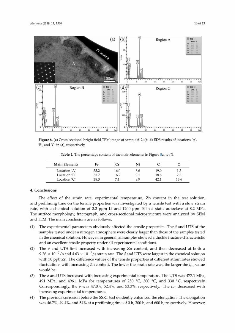
Figure 8. (a) Cross-sectional bright field TEM image of sample #12; (b–d) EDS results of locations ‘A’, ‘B’, and ‘C’ in (a), respectively.
Table 4. The percentage content of the main elements in Figure 8a, wt %.
Main Elements Fe Cr Ni C O Location ‘A’ 55.2 16.0 8.6 19.0 1.3 Location ‘B’ 53.7 16.2 9.1 18.6 2.3 Location ‘C’ 28.3 7.1 8.9 42.1 13.6
4. Conclusions
The effect of the strain rate, experimental temperature, Zn content in the test solution, and prefilming time on the tensile properties was investigated by a tensile test with a slow strain rate, with a chemical solution of 2.2 ppm Li and 1200 ppm B in a static autoclave at 8.2 MPa. The surface morphology, fractograph, and cross-sectional microstructure were analyzed by SEM and TEM. The main conclusions are as follows:
(1) The experimental parameters obviously affected the tensile properties. The δ and UTS of the samples tested under a nitrogen atmosphere were clearly larger than those of the samples tested in the chemical solution. However, in general, all samples showed a ductile fracture characteristic and an excellent tensile property under all experimental conditions.
(2) The δ and UTS first increased with increasing Zn content, and then decreased at both a 9.26 × 10⁻⁷/s and 4.63 × 10⁻⁷/s strain rate. The δ and UTS were largest in the chemical solution with 50 ppb Zn. The difference values of the tensile properties at different strain rates showed fluctuations with increasing Zn content. The lower the strain rate was, the larger the Iscc value would be.
(3) The δ and UTS increased with increasing experimental temperature. The UTS was 477.1 MPa, 491 MPa, and 496.1 MPa for temperatures of 250 °C, 300 °C, and 330 °C, respectively. Correspondingly, the δ was 47.0%, 52.4%, and 53.3%, respectively. The Iscc decreased with increasing experimental temperatures.
(4) The previous corrosion before the SSRT test evidently enhanced the elongation. The elongation was 46.7%, 49.4%, and 54% at a prefilming time of 0 h, 300 h, and 600 h, respectively. However, the UTS first decreased with increasing prefilming time, and then increased. The UTS was about 496.9 MPa after previous corrosion for 600 h. Previous corrosion in the chemical solution obviously reduced the SCC susceptibility.
Figure 8. (a) Cross-sectional bright field TEM image of sample #12; (b–d) EDS results of locations ‘A’,‘B’, and ‘C’ in (a), respectively.
Table 4. The percentage content of the main elements in Figure 8a, wt %.
Main Elements Fe Cr Ni C O
Location ‘A’ 55.2 16.0 8.6 19.0 1.3Location ‘B’ 53.7 16.2 9.1 18.6 2.3Location ‘C’ 28.3 7.1 8.9 42.1 13.6
4. Conclusions
The effect of the strain rate, experimental temperature, Zn content in the test solution,and prefilming time on the tensile properties was investigated by a tensile test with a slow strainrate, with a chemical solution of 2.2 ppm Li and 1200 ppm B in a static autoclave at 8.2 MPa.The surface morphology, fractograph, and cross-sectional microstructure were analyzed by SEMand TEM. The main conclusions are as follows:
(1) The experimental parameters obviously affected the tensile properties. The δ and UTS of thesamples tested under a nitrogen atmosphere were clearly larger than those of the samples testedin the chemical solution. However, in general, all samples showed a ductile fracture characteristicand an excellent tensile property under all experimental conditions.
(2) The δ and UTS first increased with increasing Zn content, and then decreased at both a9.26 × 10−7/s and 4.63 × 10⁻⁷/s strain rate. The δ and UTS were largest in the chemical solutionwith 50 ppb Zn. The difference values of the tensile properties at different strain rates showedfluctuations with increasing Zn content. The lower the strain rate was, the larger the Iscc valuewould be.
(3) The δ and UTS increased with increasing experimental temperature. The UTS was 477.1 MPa,491 MPa, and 496.1 MPa for temperatures of 250 ◦C, 300 ◦C, and 330 ◦C, respectively.Correspondingly, the δ was 47.0%, 52.4%, and 53.3%, respectively. The Iscc decreased withincreasing experimental temperatures.
(4) The previous corrosion before the SSRT test evidently enhanced the elongation. The elongationwas 46.7%, 49.4%, and 54% at a prefilming time of 0 h, 300 h, and 600 h, respectively. However,

Materials 2018, 11, 1509 11 of 13
the UTS first decreased with increasing prefilming time, and then increased. The UTS wasabout 496.9 MPa after previous corrosion for 600 h. Previous corrosion in the chemical solutionobviously reduced the SCC susceptibility.
(5) Many particles with a polyhedron shape were formed on the sample surfaces, which wasattributed to corrosion in a periodical location at the sample surface. The average lengthof the formed particles decreased with increasing Zn content, but increased with increasingexperimental temperatures. The longer the previous corrosion time was, the larger the averagelength of particles would be.
Author Contributions: G.R. conceived and designed the experiments; Y.H., W.W., and S.C. performed theexperiments; D.C. and Y.H obtained SEM images; N.L modified manuscript; and Y.H. analyzed the data andwrote the manuscript under the supervision of G.R. All authors contributed to the scientific discussion of theresults and reviewed the manuscript.
Funding: The work was supported by National Natural Science Foundation of China, through GrantNo. U1832112, the International Science & Technology Cooperation Program of China, through GrantNo. 2015DFR60370 and National major scientific research equipment development of China, through GrantNo. 11227804
Conflicts of Interest: The authors declare no conflict of interest.
References
1. Nezakat, M.; Akhiani, H.; Penttilä, S.; Sabet, S.M.; Szpunar, J. Effect of thermo-mechanical processing onoxidation of austenitic stainless steel 316L in supercritical water. Corros. Sci. 2015, 94, 197–206. [CrossRef]
2. Was, G.S.; Ampornrat, P.; Gupta, G.; Teysseyre, S.; West, E.A.; Allen, T.R.; Sridharan, K.; Tan, L.; Chen, Y.;Ren, X.; et al. Corrosion and stress corrosion cracking in supercritical water. J. Nucl. Mater. 2007, 371, 176–201.[CrossRef]
3. Zhang, L.; Chen, K.; Wang, J.; Guo, X.; Du, D.; Andresen, P.L. Effects of zinc injection on stress corrosioncracking of cold worked, austenitic stainless steel in high-temperature water environments. Scr. Mater. 2017,140, 50–54. [CrossRef]
4. Terachi, T.; Yamada, T.; Miyamoto, T.; Arioka, K. SCC growth behaviors of austenitic stainless steels insimulated PWR primary water. J. Nucl. Mater. 2012, 426, 59–70. [CrossRef]
5. Liu, X.; Wu, X.; Han, E.H. Influence of Zn injection on characteristics of oxide film on 304 stainless steel inborated and lithiated high temperature water. Corros. Sci. 2011, 53, 3337–3345. [CrossRef]
6. Betova, I.; Bojinov, M.; Kinnunen, P.; Saario, T. Zn injection in Pressurized Water Reactors–laboratory tests,field experience and modelling. In Research Report No. VTT-R-05511-11; Technical Research Center of Finland:Espoo, Finland, 2011.
7. Marks, C.; Dumouchel, M.; Reid, R.; White, G. Quantifying the benefit of chemical mitigation of PWSCCvia zinc addition or hydrogen optimization. In Proceedings of the 15th International Conference onEnvironmental Degradation of Materials in Nuclear Power System-Water Reactors, Colorado Springs,CO, USA, 7–11 August 2011; John Wiley & Sons, Inc.: Hoboken, NJ, USA, 2011; pp. 1893–1906.
8. Norring, K.; Engström, J. Initiation of SCC in nickel base alloys in primary PWR environment: Studies atStudsvik since mid 1980s. Energy Mater. 2008, 3, 113–118. [CrossRef]
9. Piippo, J.; Saario, T.; Tegeder, V.; Stellwag, B. Influence of zinc on properties and growth of oxide layers insimulated primary coolant. In Proceedings of the 7th International Conference on the Water Chemistry ofNuclear Reactor Systems, Bournemouth, UK, 13–17 October 1996; Thomas Telford Services LTD.: London,UK, 1996; pp. 131–134.
10. Ziemniak, S.E.; Hanson, M. Zinc treatment effects on corrosion behavior of Alloy 600 in high temperature,hydrogenated water. Corros. Sci. 2006, 48, 3330–3348. [CrossRef]
11. Liu, X.; Wu, X.; Han, E.H. Electrochemical and surface analytical investigation of the effects of Znconcentrations on characteristics of oxide films on 304 stainless steel in borated and lithiated high temperaturewater. Electrochim. Acta 2013, 108, 554–565. [CrossRef]
12. Betova, I.; Bojinov, M.; Kinnunen, P.; Lundgren, K.; Saario, T. Influence of Zn on the oxide layer on AISI 316L(NG) stainless steel in simulated pressurized water reactor coolant. Electrochim. Acta 2009, 54, 1056–1069.[CrossRef]

Materials 2018, 11, 1509 12 of 13
13. Huang, J.; Liu, X.; Han, E.H.; Wu, X. Influence of Zn on oxide films on Alloy 690 in borated and lithiatedhigh temperature water. Corros. Sci. 2011, 53, 3254–3261. [CrossRef]
14. Kim, Y.J.; Andresen, P.L. Transformation kinetics of oxide formed on noble metal-treated type 304 stainlesssteel in 288 ◦C water. Corrosion 2003, 56, 511–519. [CrossRef]
15. Pathania, R.S.; Cheng, B.O. Evaluation of zinc addition to the primary coolant of Farley-2 PWR.Nucl. Power Plant 1998, 31, 959–971.
16. Hanzawa, Y.; Hiroishi, D.; Matsuura, C.; Ishigure, K. Solubility of zinc ferrite in high-temperature oxygenatedwater. J. Nucl. Mater. 1998, 252, 209–215. [CrossRef]
17. Liu, X.; Wu, X.; Han, E.H. Effect of Zn injection on established surface oxide films on 316 L stainless steel inborated and lithiated high temperature water. Corros. Sci. 2012, 65, 136–144. [CrossRef]
18. Lu, Z.; Shoji, T.; Meng, F.; Qiu, Y.; Dan, T.; Xue, H. Effects of water chemistry and loading conditions onstress corrosion cracking of cold-rolled 316NG stainless steel in high temperature water. Corros. Sci. 2011, 53,247–262. [CrossRef]
19. Toppo, A.; Pujar, M.G.; Mallika, C.; Mudali, U.K.; Dayal, R.K. Effect of nitrogen on stress corrosion behaviorof austenitic stainless steels using electrochemical noise technique. J. Mater. Eng. Perform. 2015, 24, 1140–1149.[CrossRef]
20. Furutani, G.; Nakajima, N.; Konishi, T.; Kodama, M. Stress corrosion cracking on irradiated 316SS.J. Nucl. Mater. 2001, 288, 179–186. [CrossRef]
21. Totsuka, N.; Nishikawa, Y.; Kaneshima, Y. Effect of strain rate on primary water stress corrosion crackingfracture mode and crack growth rate of nickel alloy and austenitic stainless steel. Corrosion 2005, 61, 219–229.[CrossRef]
22. Liu, X.; Han, E.H.; Wu, X. Effects of pH value on characteristics of oxide films on 316L stainless steel inZn-injected borated and lithiated high temperature water. Corros. Sci. 2014, 78, 200–207. [CrossRef]
23. Zhang, S.; Shi, R.; Chen, Y.; Wang, M. Corrosion behavior of oxide films on AISI 316L SS formed in hightemperature water with simultaneous injection of zinc and aluminum. J. Alloy. Compd. 2018, 731, 1230–1237.[CrossRef]
24. Andresen, P.L.; Wilson, J.A.; Ahluwalia, K.S. Use of primary water chemistry in PWRs to mitigate PWSCC ofNi-Base alloys. Presented at the International Conference on Water Chemistry of Nuclear Reactor Systems,Jeju Island, Korea, 23–26 October 2006.
25. Kawamura, H.; Hirano, H.; Shirai, S.; Takamatsu, H.; Matsunaga, T.; Yamaoka, K.; Oshinden, K.; Takiguchi, H.Inhibitory effect of zinc addition to high-Temperature hydrogenated water on mill-annealed and prefilmedAlloy 600. Corrosion 2000, 56, 623–637. [CrossRef]
26. Angell, M.G.; Allan, S.J.; Airey, G.P. The effect of primary coolant zinc additions on the SCC behavior of alloy600 and 690. In Proceedings of the 9th International Conference on Environmental Degradation of Materialsin Nuclear Power System—Water Reactors, Newport Beach, USA, 1–5 August 1999; John Wiley & Sons, Inc.:Hoboken, NJ, USA, 1999; pp. 96–103.
27. Maeng, W.Y.; Cho, Y.S.; Kim, U.C. Effect of Zn injection on the SCC crack growth of Alloy 600 in water at360 ◦C. Presented at the International Conference on Water Chemistry of Nuclear Reactor Systems, JejuIsland, Korea, 23–26 October 2006.
28. Jones, R.H.; Henager, C.H., Jr. Effect of gamma irradiation on stress corrosion behavior of austenitic stainlesssteel under ITER-relevant conditions. J. Nucl. Mater. 1992, 191–194, 1012–1017. [CrossRef]
29. Brnic, J.; Niu, J.; Canadija, M.; Turkalj, G.; Lanc, D. Behavior of AISI 316L steel subjected to uniaxial state ofstress at elevated temperatures. J. Mater. Sci. Technol. 2009, 25, 175–179.
30. Wang, J.; Wang, J.; Ming, H.; Zhang, Z.; Han, E.H. Effect of temperature on corrosion behavior of Alloy 690in high temperature hydrogenated water. J. Mater. Sci. Technol. 2017, 16, 230–242. [CrossRef]
31. Lee, D.; Huang, Y.; Achenbach, J.D. A comprehensive analysis of the growth rate of stress corrosion cracks.Proc. R. Soc. A 2015, 471, 20140703. [CrossRef]
32. Wang, J.; Wang, J.; Ming, H.; Zhang, Z.; Han, E.H. Modelling of stress-corrosion cracking by usingperidynamics. Int. J. Hydrogen Energy 2016, 41, 6593–6609.
33. Lister, D.H. Activity transport and corrosion processes in PWRs. Nucl. Energy 1993, 32, 103–114.34. Ziemniak, S.E.; Hanson, M. Corrosion behavior of NiCrFe alloy 600 in high temperature, hydrogenated
water. Corros. Sci. 2006, 48, 498–521. [CrossRef]

Materials 2018, 11, 1509 13 of 13
35. Katada, Y.; Nagata, N. The effect of temperature on fatigue crack growth behaviour of a low alloy pressurevessel steel in a simulated BWR environment. Corros. Sci. 1985, 25, 693–704. [CrossRef]
36. Atkinson, J.D.; Yu, J. The role of dynamic strain-ageing in the environment assisted cracking observed inpressure vessel steels. Fatigue Fract. Eng. Mater. Struct. 1997, 20, 1–12. [CrossRef]
37. Tang, Z.; Hu, S.; Zhang, P. Stress corrosion cracking of 316Ti in 300 ◦C high temperature water containingchloride ions. J. Chin. Soc. Corros. Prot. 2012, 32, 32–291. [CrossRef]
38. Kim, Y.J. Characterization of the oxide film formed on type 316 stainless steel in 288 ◦C water in cyclicnormal and hydrogen water chemistries. Corrosion 1995, 51, 849–860. [CrossRef]
39. Kim, Y.J. Analysis of oxide film formed on type 304 stainless steel in 288 ◦C water containing oxygen,hydrogen, and hydrogen peroxide. Corrosion 1999, 55, 81–88. [CrossRef]
40. Ziemniak, S.E.; Hanson, M. Zinc treatment effects on corrosion behavior of 304 stainless steel in hightemperature, hydrogenated water. Corros. Sci. 2006, 48, 2525–2546. [CrossRef]
41. Ehrnstén, U. Corrosion and stress corrosion cracking of austenitic stainless steels. Compr. Nucl. Mater. 2012,93–104. [CrossRef]
© 2018 by the authors. Licensee MDPI, Basel, Switzerland. This article is an open accessarticle distributed under the terms and conditions of the Creative Commons Attribution(CC BY) license (http://creativecommons.org/licenses/by/4.0/).