Embed Size (px)
Citation preview
Stress concentration in periodically rough hertzian contact: Hertz tosoft-flat-punch transition
Rene Ledesma-Alonso1,2,† , Elie Raphael1, Liliane Leger2, Frederic Restagno2, and Christophe Poulard2
1Laboratoire de Physico-Chimie Theorique, UMR CNRS 7083 Gulliver, ESPCI ParisTech, PSL ResearchUniversity, 10 Rue Vauquelin, 75005 Paris, France
2Laboratoire de Physique des Solides, CNRS, Univ. Paris-Sud, Universite Paris-Saclay, 91400 Orsay,France
†e-mail: [email protected]
July 4, 2016
Abstract
We report on the elastic contact between a spherical lens and a patterned substrate, composed of an hexagonallattice of cylindrical pillars. The stress field and the size of the contact area are obtained by means of numericalmethods: a superposition method of discrete pressure elements and an iterative bisection-like method. For smallindentations, a transition from a Hertzian to a soft-flat-punch behavior is observed when the surface fraction ofthe substrate that is covered by pillars is increased. In particular, we present a master curve defined by two di-mensionless parameters, which allows to predict the stress at the center of contact region in terms of the surfacefraction occupied by pillars. The transition between the limiting contact regimes, Hertzian and soft-flat-punch, iswell described by a rational function. Additionally, a simple model to describe the Boussines-Cerruti-like contactbetween the lens and a single elastic pillar, which takes into account the pillar geometry and the elastic propertiesof the two bodies, is presented.
Keywords: Patterned substrate, surface fraction, stress concentration, real contact area, Hertz to soft-flat-punchtransition.
1 IntroductionThe contact mechanics between an elastic sphere and a flat elastic solid, with frictionless, perfectly smooth andnon-conforming surfaces, is beautifully provided by the Hertz theory [1]. From the knowledge of the geometry(sphere radius R), the elastic properties (Young modulus and Poisson’s ratio) and the total load F compressingthe two elastic solids, one can forecast the radius of contact a ∼ 3
√RF , the total indentation ζ ∼ 3
√F 2/R of
the two bodies, and the maximum pressure σ0H ∼ 3√F/R2. When adhesion between the two bodies in contact
is considered, several modifications from the Hertz theory have been proposed: 1) the Johnson-Kendall-Roberts(JKR) model, which accounts for the attractive surface forces inside the contact region, predicts a larger contactradius than the Hertzian value and applies for soft materials, 2) the Derjaguin-Muller-Toporov (DMT) model,which considers that the attractive forces act only outside the contact region, infers a Hertzian contact profile butwith larger deformations (compared to the Hertz theory) for the same load, and suits for hard materials. Finallythe Maugis-Dugdale (MD) model describes an unified way in precisely the transition between the two previousmodels.
However, real surfaces are not smooth and the contact mechanics of two real bodies can bitterly deviate fromthe Hertzian predictions since only partial contact can occur [1, 2, 3]. Attention has been paid to this problem fromtwo different points of departure, the first based on a statistical approach of real surfaces and the second on thedeterministic behavior of periodic surfaces.
On one hand, the statistical approach to the contact mechanics of real surfaces bifurcates into three branches.First, considering the contact between a plane and an isotropically rough surface composed of non-interacting“spherical asperities” with a vertical position given by a distribution of heights (exponential and Gaussian) [4,5, 6], from which estimations of the number of contact spots, the contact area and the total load were obtained
1
arX
iv:1
604.
0016
6v2
[co
nd-m
at.m
trl-
sci]
1 J
ul 2
016
in terms of the apparent contact area, the density of asperities, the radius of curvature of the asperities and afunction of the heights distribution. In particular, it has been found that the number of asperities in contact andthe real contact area are both proportional to the total load [4], and the ratio of the roughness to the indentationhas been proposed as a parameter to account for the influence of the roughness on the contact mechanics [5, 6].Additionally, useful empirical elasto-plastic models can be found in the recent literature [7, 8], which considernominally rough surfaces and are based on the above-mentioned statistical approaches. Second, a similar approachto the previous one was developed, but considering a distribution for the shapes of the asperities, i.e. an isotropicallyrough surface composed of non-interacting “paraboloid-like asperities” with a Gaussian distribution of the slopesand curvatures [9]. It has been shown that considering a roughness, given by a bandwidth of wavelengths, thereal contact area is strictly proportional to the load and, thus, the stress distribution at the average asperity contactregion remains unchanged. Nevertheless, the two above mentioned approaches break down for large loads, atwhich the separation between the contact surfaces becomes small and the interaction between adjoining asperitiescannot be neglected. Finally, the surface roughness power spectrum, for instance self-affine fractal surfaces andfrozen capillary waves, was employed to estimate the ratio between the real and apparent contact areas [10]. Thisdescription is particularly accurate for high loads and it is based on the knowledge of the stress distribution, whichdepends on the average pressure and the magnification (the ratio between size of the apparent contact area andthe shortest wavelength roughness). It also predicts a linear dependence of the real contact area on the total load,for small loads and small real-to-apparent contact area ratios. Even though the aforementioned statistical methodsprovide average quantities and global insight of the rough contact phenomenon, the local stress and displacementfields at the contact spots remain inaccessible since the surface topography may not be persistent from one body toanother.
On the other hand, in order to gain insight on the local response of the bodies in contact, periodic contact prob-lems have been addressed [11, 12]. For instance the contact between a flat surface and a well-characterized 1Dwavy surface, of wavelength λ and amplitude δ, has been addressed by superposition of concentrated normal forcesat the surface of an infinite half-space (Boussinesq-Cerruti approach). In this situation, a close-form solution for thestress and displacement fields is obtained and we should encourage the interested reader to review the aforemen-tioned bibliography. However, we should mention that for a given line load F , the local contact occurs in bandsof increasing width 2a that obey the scaling F ∼ δ sin2 (πaλ) with a maximum stress σ0 ∼ (δ/λ) sin (πa/λ).Following the same ideas, a well-characterized 2D regular and orthogonal wavy surface was analyzed but onlyasymptotic behaviors have been discerned. In particular, for light loads, a local Hertzian behavior is expected atthe contact between the plane and each summit of the wavy surface, a nearly circular region of contact of radiusa ∼ 3
√F is observed. Despite these efforts, the size of the contact region and the stress field provoked by the
contact of rough finite-size surfaces remains not predicted by the discussed deterministic method.Understanding the contact mechanics of rough surfaces, starting with well-controlled patterned surfaces, is
fundamental in order to clarify the effect of pattern covering on friction [13, 14, 15, 16, 17, 18], or to identify theinfluence of texturation on the adhesive properties of surfaces [19, 20, 21, 22]. This query has received a lot ofattention since patterned surfaces have been extensively used as biomimetic surfaces[23, 24, 25, 26, 27, 28]. Fromthis point of view, one of the important issues is the contact formation, which fixes the relationship between themeasured adhesion and the preload before the detachment [29, 30].
In the simplest case of a spherical lens on well-controlled patterned surface made on elastomeric PDMS with cir-cular bumps and cylindrical pillars, a transition from suspended (the lens touches only the top of the bumps/pillars)to intimate contact (the lens gets in contact not only with the bumps/pillars but also with the underlying substrate inbetween the patterns) has been observed. The contact formation has been shown to depend strongly on the geome-try and elastic properties of the textured surface [3, 31, 32, 33]. In particular, Verneuil and coworkers have shownthat the one leading parameter is the surface fraction Φ occupied by the pillars, since the critical force, which marksthe threshold between both contact regimes, scales as Fc ∼ Φ3.
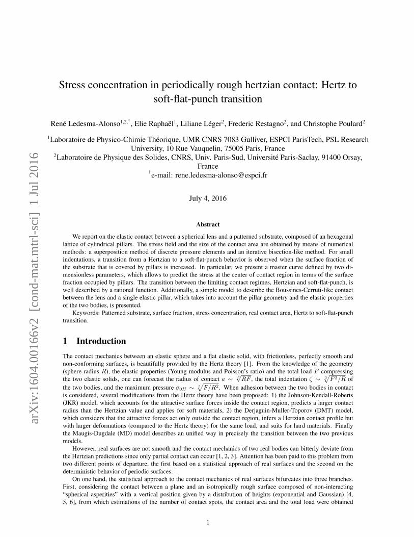
Therefore, there is no doubt about the central role that the surface fraction Φ plays in the distribution of stressesand in ascertaining the size of the contact region. The geometry of a sphere in contact with an array of cylindricalpillars is represented graphically in Fig.1. When Φ→ 1, a classic problem consisting in the contact mechanics of asphere and a half-space is recovered, for which the stress and displacement fields are described by the Hertz theory.At the opposite limit, when Φ→ 0 the contact mechanics is no longer a Hertzian contact but should be representedby the compression of a half-space and a cylindrical pillar, as depicted in Fig.1. The indentation of an elastic halfspace by a flat rigid punch is described by the classical Boussinesq-Cerruti solution, which is obtained either by thesuperposition of concentrated normal forces [1, 34] or by means of a Hankel transform method with an imposedsurface displacement [35, 36]. As well, an analysis, which has remained out of focus, presents a numerical solutionthat provides the transition from the limit case of the contact between a rigid punch and an elastic half-space tothe opposite case of an elastic cylinder and a rigid flat surface [37]. Nevertheless, the passage from one regime toanother is not obvious and work must be done to describe clearly this phenomenon. This is precisely the object ofthe present article.
2
Patterned substrate!Hexagonal array of pillars
Soft lens
Boussinesq-Cerruti-like!contact
� ! 0
Hertzian contact
� ! 1
� &
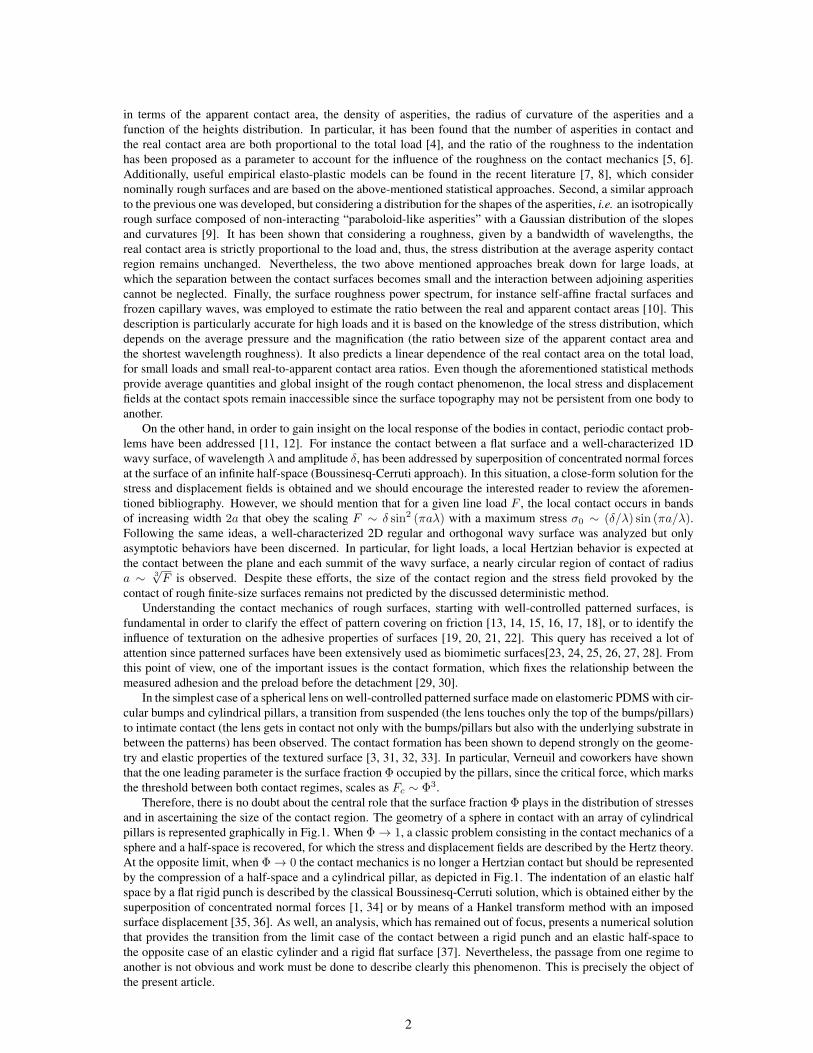
Figure 1: Illustration of the discrete contact problem studied in this manuscript and its asymptotic cases, with respect to thesurface fraction Φ of the substrate that is occupied by the pillars.
In this paper, we discuss the elastic contact between a spherical lens and patterned surface with cylindricalpillars. The presented analysis, which corresponds to a first approach on the real contact mechanics of periodicrough surfaces, considers two fundamental hypotheses: 1) frictionless contact and 2) no adhesion effects. Theimpact of elastic properties and of the geometry of the system is analyzed, with special focus on the surface fractionoccupied by the pillars. A detailed description of the transition from Hertzian contact (short pitch distance) to soft-flat-punch regime (large pitch distance), for the aforementioned lens-patterned substrate system, is presented. Wewill discuss the contact behavior for a wide range of elastic parameters (combination of Young’s modulus) anddisplacement of the bodies (total indentation), and analyze the effects of the pitch between pillars in terms of thestress concentration and the number of pillars (real contact area) within the contact region.
2 System description
de
h
Ep = Es, ⌫p = ⌫s
El, ⌫l
RSpherical lens
Wigner-Seitzcell
Patterned substrateHexagonal array of pillars
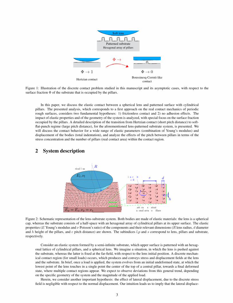
Figure 2: Schematic representation of the lens-substrate system. Both bodies are made of elastic materials: the lens is a sphericalcap, whereas the substrate consists of a half-space with an hexagonal array of cylindrical pillars at its upper surface. The elasticproperties (E Young’s modulus and ν Poisson’s ratio) of the components and their relevant dimensions (R lens radius, d diameterand h height of the pillars, and e pitch distance) are shown. The subindices l,p and s correspond to lens, pillars and substrate,respectively.
Consider an elastic system formed by a semi-infinite substrate, which upper surface is patterned with an hexag-onal lattice of cylindrical pillars, and a spherical lens. We imagine a situation, in which the lens is pushed againstthe substrate, whereas the latter is fixed at the far-field, with respect to the lens initial position. A discrete mechan-ical contact region (for small loads) occurs, which produces and conveys stress and displacement fields at the lensand the substrate. In brief, once a load is applied, the system evolves from an initial undeformed state, at which thelowest point of the lens touches in a single point the center of the top of a central pillar, towards a final deformedstate, where multiple contact regions appear. We expect to observe deviations from this general trend, dependingon the specific geometry of the system and the magnitude of the applied load.
Herein, we consider another important hypothesis: the effect of lateral displacement, due to the discrete stressfield is negligible with respect to the normal displacement. Our intuition leads us to imply that the lateral displace-
3
ment provoked by a single pillar is canceled by the lateral displacement generated by the surrounding pillars and,as a result, the superposition of the effects of all the pillars can be neglected. In addition, also due to the aforemen-tioned idea, the patterned substrate can be further separated. To be more precise, the system, represented in Fig.2,can be decomposed into several independent bodies: 1) a spherical lens, a cap that corresponds to the lower regionof a sphere of radius R; 2) a flat substrate, which we will take as an elastic half-space; and 3) an array of cylinders,where d and h are the diameter and height of each pillar, whereas e is the pitch, the distance between the center oftwo pillars.
2.1 Array of pillarsWhen the lens is pushed against the patterned substrate, the number of pillars in contact Q can be estimated byusing the Wigner-Seitz cell of an hexagonal lattice of pillars (see Fig.2). Computing the fraction of the surfaceoccupied by the pillars:
Φ =π
2√
3
(d
e
)2
, (1)
and, considering a circular region of radius a as the apparent contact zone, the number of pillars in contact becomes:
Q ≈ 2π√3
(ae
)2. (2)
Nevertheless, one cannot predict an accurate number of pillars Q because the apparent contact radius a is unknowna priori. Despite this fact, in the present study we will consider that R � d/2 and R � a which corresponds to alot of practical situations previously studied in the literature.
Considering a polar system (r, θ), the position of the center of the ith pillar is given by the coordinates (ri, θi),where the value of i = 0 corresponds to the pillar which center is placed at the origin of the coordinate system. Adetailed description of the pillar array and the precise method to enumerate the pillars and to count the number ofpillars in contact is given in the supplementary material [38].
2.2 Displacement and indentationBefore the lens and patterned substrate are squeezed and the deformation of both bodies takes place, the center ofthe spherical lens is placed at z = h+R. In turn, the equation of the pillars-substrate surface is:
g◦ (r, θ) = h
Q∑
i=0
[1−H
(ρi −
d
2
)], (3)
where H is a Heaviside step function, taking either the value of 0 if ρi ≤ d/2 or 1 if ρi > d/2. As described in thesupplementary material [38], relative to the center of the ith pillar, which is placed at (ri, θi), ρi is the distance tothe point (r, θ), given by:
ρi =√r2 + r2i − 2rri cos (θ − θi) . (4)
These initial positions indicate that the lens and the patterned substrate are in contact at a single point, at r = 0where the lowest position of the lens touches the center of the pillar upper surface.
Once the load is applied and the system has attained equilibrium, the final gap between the surfaces, the spaceseparating the lens and the pillars-substrate body, is now given by:
∆ (r, θ) = h+R−√R2 − r2 − g◦ (r, θ) + w (r, θ)− ζ , (5)
where w(r, θ) is the total displacement field and ζ = w (0, θ) is the indentation, i.e. the displacement at the center.For light loads and within the apparent contact region, only the top of the pillars can be in contact with the lens,whereas the substrate not covered by pillars will be separated from the lens by a gap. In addition, one may noticethat, within the contact region, the top of each pillar may be either in total or partial contact. Whatever the contactsituation of each pillar, at the local contact regions, one has ∆ (r, θ) = 0 and g◦ (r, θ) = h, and thus the totaldisplacement field w (r, θ) is related to the total indentation ζ as follows:
w (r, θ) = ζ −[R−
√R2 − r2
]. (6)
4
3 Discrete contactFor each body j (lens j = l, array of pillars j = p and substrate j = s), considering its Young’s elastic modulus Ejand Poisson’s ratio νj , we define the parameter γj =
[1− ν2j
]/Ej . Herein, we will always consider that the pillars
and the substrate are made of the same material, thus Ep = Es and νp = νs. As mentioned above, when thesebodies are brought into contact, i.e. the lens is approached towards the pillars, which in turn pushes the substrate,they suffer a deformation. Under these circumstances, recalling that the vertical displacement at the surface of ahalf-space uz due to a concentrated point force Σ is given by [1]:
uz (Σ, r) =γΣ
πr, (7)
and applying the principle of linear superposition, the normal displacement of the spherical lens and the substrate(j = l, s) reads:
wj (r, θ) =
∫∫
Auz (σ, %) %d%dϕ , (8)
where σ = σ (%, ϕ) is the stress field over the apparent contact area A, which is described by % and ϕ, the radialand angular coordinates relative to the point (r, θ). In other words, the displacement wj at the point (r, θ) is theeffect of the stress field applied over a region described by the set of relative positions (%, ϕ). Due to the discretenature of the contact, the normal displacement of each surface can be decomposed as follows:
wj (r, θ) =γjπ
Q∑
i=0
Wi (r, θ, ri , θi) , Wi (r, θ, ri , θi) =
∫ ϕi2
ϕi1
∫ %i2
%i1
σ (%, ϕ) d%dϕ , (9)
whereWi is the reduced displacement at (r, θ) due to the contact with the ith pillar. Additionally, we make emphasison the fact that the displacement field Wi depends explicitly on the position of the ith pillar , since the integrationlimits %i1, %i2, ϕi1 and ϕi2 must be determined for each combination of pillar location (ri , θi) and point (r, θ). Forinstance, %i1 and %i2 are the solutions for % of quadratic equation:
%2 − [2ρi cos (ϕ)] %+[(ρi)
2 − (d/2)2]
= 0 , (10)
where ρi = ρi (r, θ, ri, θi) given in eq. 4, whereas ϕi1 and ϕi2 depend on the location of the point (r, θ). On onehand, if (r, θ) lies inside the contact region of the ith pillar, we have ϕi1 = 0 and ϕi2 = π, and, on the other hand,if (r, θ) is located outside the contact region of the ith pillar, we find:
ϕi1,2 = ± arcsin
([d/2] sin (π/2)
ρi
). (11)
In turn, each pillar is compressed because of its confinement between the lens and the substrate. Herein, weconsider that the compression of the ith pillar is approximated by the Hooke’s law, which gives a change of heightequal to δi = 4hFi/
(πd2Ep
). As well, Fi is the load exerted over the ith pillar in the contact region, which reads:
Fi (ri, θi) =
∫ 2π
0
∫ d/2
0
σ (ρi, φi) ρidρidφi , (12)
whereas, in this situation, ρi and φi represent the radial and angular coordinates at the surface of the ith pillar,relative to the pillar center (ri, θi) and restricted to the ranges ρi ∈ [0, d/2] and φi ∈ [0, 2π]. In order to transformthe stress field over the entire domain σ (r, θ) into σ (ri, θi, ρi, φi), one should express r and θ for a given relativeposition (ρi, φi) and a pillar (ri, θi) using the following expressions:
r =√ρ2i + r2i + 2ρiri cos (φi − θi) , θ = arcsin
(ρi sin (π − φi) + ri sin (θi)
r
). (13)
Additionally, the total load FT reads:
FT =
∫∫
Aσ (r, θ) rdrdθ , (14)
which, accounting with the discrete nature of the contact, can be obtained by adding the contribution of each pillaras follows:
FT =
Q∑
i=0
Fi (ri, θi) . (15)
5
Since, the total displacement field is also composed of:
w (r, θ) = wl (r, θ) + ws (r, θ) + δig◦ (r, θ) /h , (16)
which gathers the displacement contributions given in eq. (9) and the Hookean pillar compression δi, imposing atotal indentation, given by eq.(6) and evaluated at the top of the pillars where g◦ (r, θ) = h, allows one to recoverthe stress field σ inside the contact region. Herein, σ is computed numerically using a superposition method ofdiscrete pressure elements, for which a segmentation of each contact region (the top of each pillar) into squaresubregions of constant constraint is performed. Details are given in the supplementary material [38]. A similarapproach has been introduced and validated in previous studies [39, 40], for which a Hookean hypothesis and auniform pressure has been applied to each pillar. Even though our methodology retains the Hookean behavior foreach pillar, it allows the appearance of non-axysimmetric pressure fields for the non-centered pillars (i > 0), thanksto the discretization of each contact region. This procedure provides a more realistic approach for several cases,including small total loads FT and small surface fractions Φ, but also the effect of the finite size of the contact area,for any load and any surface fraction. The corresponding results are presented in the following section.
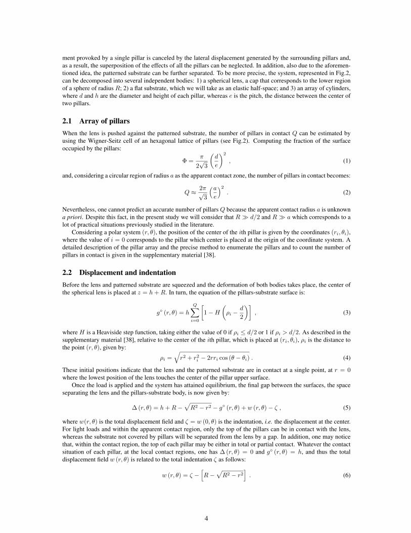
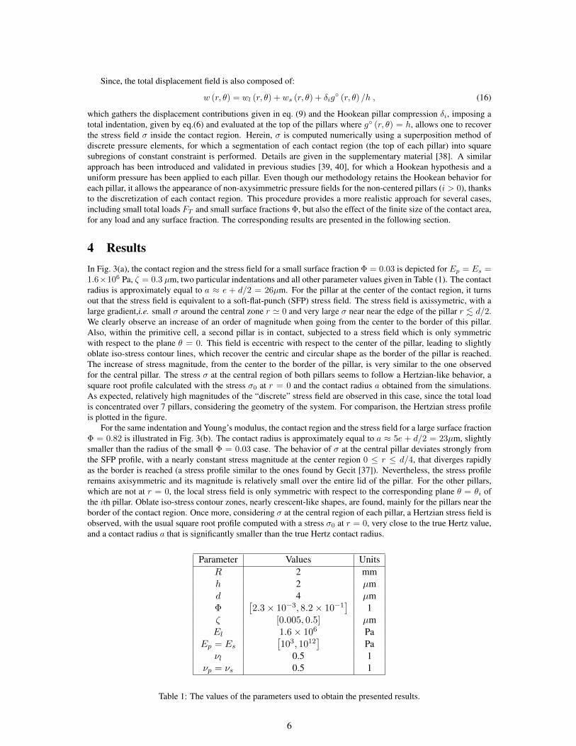
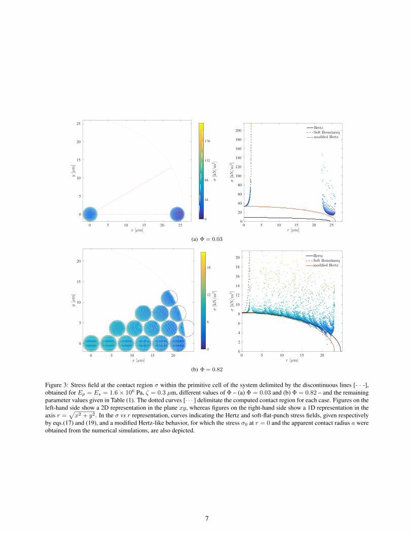
4 ResultsIn Fig. 3(a), the contact region and the stress field for a small surface fraction Φ = 0.03 is depicted for Ep = Es =1.6×10⁶ Pa, ζ = 0.3 µm, two particular indentations and all other parameter values given in Table (1). The contactradius is approximately equal to a ≈ e + d/2 = 26µm. For the pillar at the center of the contact region, it turnsout that the stress field is equivalent to a soft-flat-punch (SFP) stress field. The stress field is axissymetric, with alarge gradient,i.e. small σ around the central zone r ' 0 and very large σ near near the edge of the pillar r . d/2.We clearly observe an increase of an order of magnitude when going from the center to the border of this pillar.Also, within the primitive cell, a second pillar is in contact, subjected to a stress field which is only symmetricwith respect to the plane θ = 0. This field is eccentric with respect to the center of the pillar, leading to slightlyoblate iso-stress contour lines, which recover the centric and circular shape as the border of the pillar is reached.The increase of stress magnitude, from the center to the border of the pillar, is very similar to the one observedfor the central pillar. The stress σ at the central region of both pillars seems to follow a Hertzian-like behavior, asquare root profile calculated with the stress σ0 at r = 0 and the contact radius a obtained from the simulations.As expected, relatively high magnitudes of the “discrete” stress field are observed in this case, since the total loadis concentrated over 7 pillars, considering the geometry of the system. For comparison, the Hertzian stress profileis plotted in the figure.
For the same indentation and Young’s modulus, the contact region and the stress field for a large surface fractionΦ = 0.82 is illustrated in Fig. 3(b). The contact radius is approximately equal to a ≈ 5e + d/2 = 23µm, slightlysmaller than the radius of the small Φ = 0.03 case. The behavior of σ at the central pillar deviates strongly fromthe SFP profile, with a nearly constant stress magnitude at the center region 0 ≤ r ≤ d/4, that diverges rapidlyas the border is reached (a stress profile similar to the ones found by Gecit [37]). Nevertheless, the stress profileremains axisymmetric and its magnitude is relatively small over the entire lid of the pillar. For the other pillars,which are not at r = 0, the local stress field is only symmetric with respect to the corresponding plane θ = θi ofthe ith pillar. Oblate iso-stress contour zones, nearly crescent-like shapes, are found, mainly for the pillars near theborder of the contact region. Once more, considering σ at the central region of each pillar, a Hertzian stress field isobserved, with the usual square root profile computed with a stress σ0 at r = 0, very close to the true Hertz value,and a contact radius a that is significantly smaller than the true Hertz contact radius.
Parameter Values UnitsR 2 mmh 2 µmd 4 µmΦ
[2.3× 10⁻³, 8.2× 10⁻¹
]1
ζ [0.005, 0.5] µmEl 1.6× 10⁶ Pa
Ep = Es
[103, 1012
]Pa
νl 0.5 1νp = νs 0.5 1
Table 1: The values of the parameters used to obtain the presented results.
6
0 5 10 15 20 25
x [µm]
0
5
10
15
20
25
y[µm]
0
44
88
132
176
σ[kN/m
2]
0 5 10 15 20 25
r [µm]
0
20
40
60
80
100
120
140
160
180
200
σ[kN/m
2]
HertzSoft Boussinesqmodified Hertz
(a) Φ = 0.03
0 5 10 15 20
x [µm]
0
5
10
15
20
y[µm]
0
6
12
18
σ[kN/m
2]
0 5 10 15 20
r [µm]
0
2
4
6
8
10
12
14
16
18
20
σ[kN/m
2]
HertzSoft Boussinesqmodified Hertz
(b) Φ = 0.82
Figure 3: Stress field at the contact region σ within the primitive cell of the system delimited by the discontinuous lines [- · -],obtained for Ep = Es = 1.6× 10⁶ Pa, ζ = 0.3 µm, different values of Φ – (a) Φ = 0.03 and (b) Φ = 0.82 – and the remainingparameter values given in Table (1). The dotted curves [· · · ] delimitate the computed contact region for each case. Figures on theleft-hand side show a 2D representation in the plane xy, whereas figures on the right-hand side show a 1D representation in theaxis r =
√x2 + y2. In the σ vs r representation, curves indicating the Hertz and soft-flat-punch stress fields, given respectively
by eqs.(17) and (19), and a modified Hertz-like behavior, for which the stress σ0 at r = 0 and the apparent contact radius a wereobtained from the numerical simulations, are also depicted.
7
10-3
10-2
10-1
100
Φ
0
20
40
60
80
100
σ0[kPa]
Hertz
Boussinesq-Cerruti
-3.0
-2.0
-1.0
-0.5
-0.3
0.0
0.3
0.5
1.0
2.0
3.0
6.0
log10(E
p/E
l)
(a)
0 1 2 3 4 5
πa2 [m2]×10
-9
0
0.5
1
1.5
2
2.5
3
3.5
4
4.5
5
A[m
2]
×10-9
0.002
0.009
0.011
0.019
0.025
0.036
0.057
0.074
0.101
0.120
0.145
0.179
0.227
0.296
0.403
0.580
0.686
0.823
φ
(b)
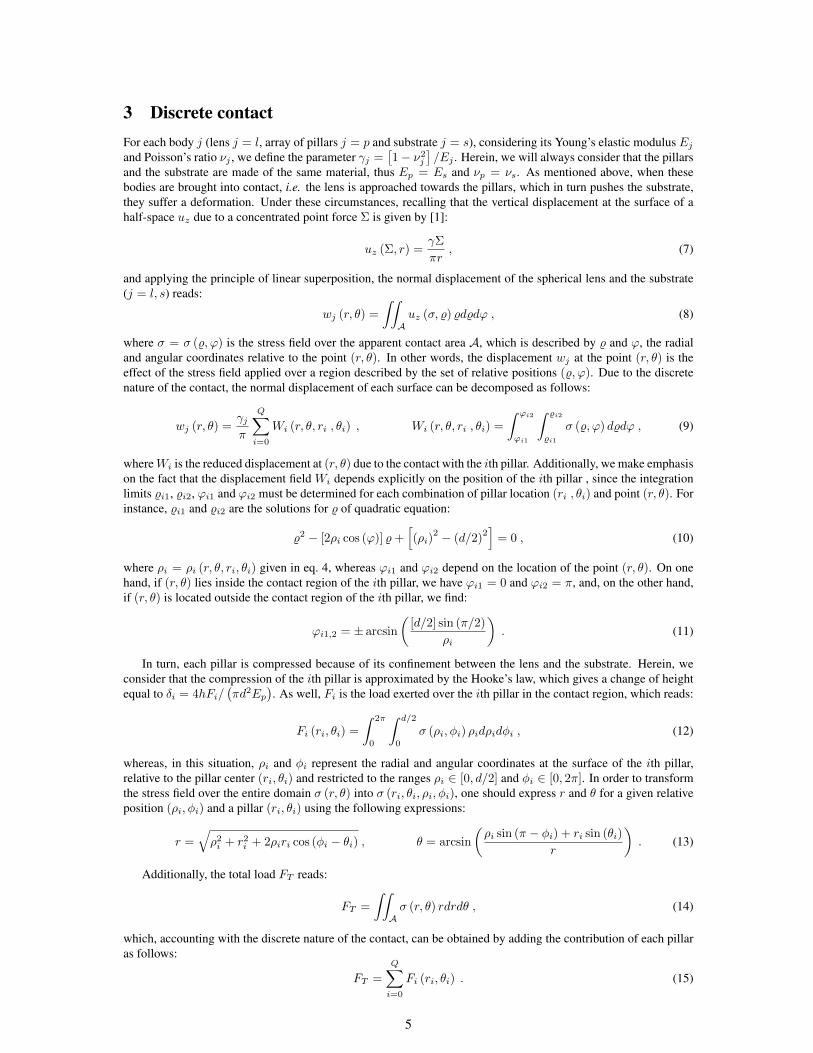
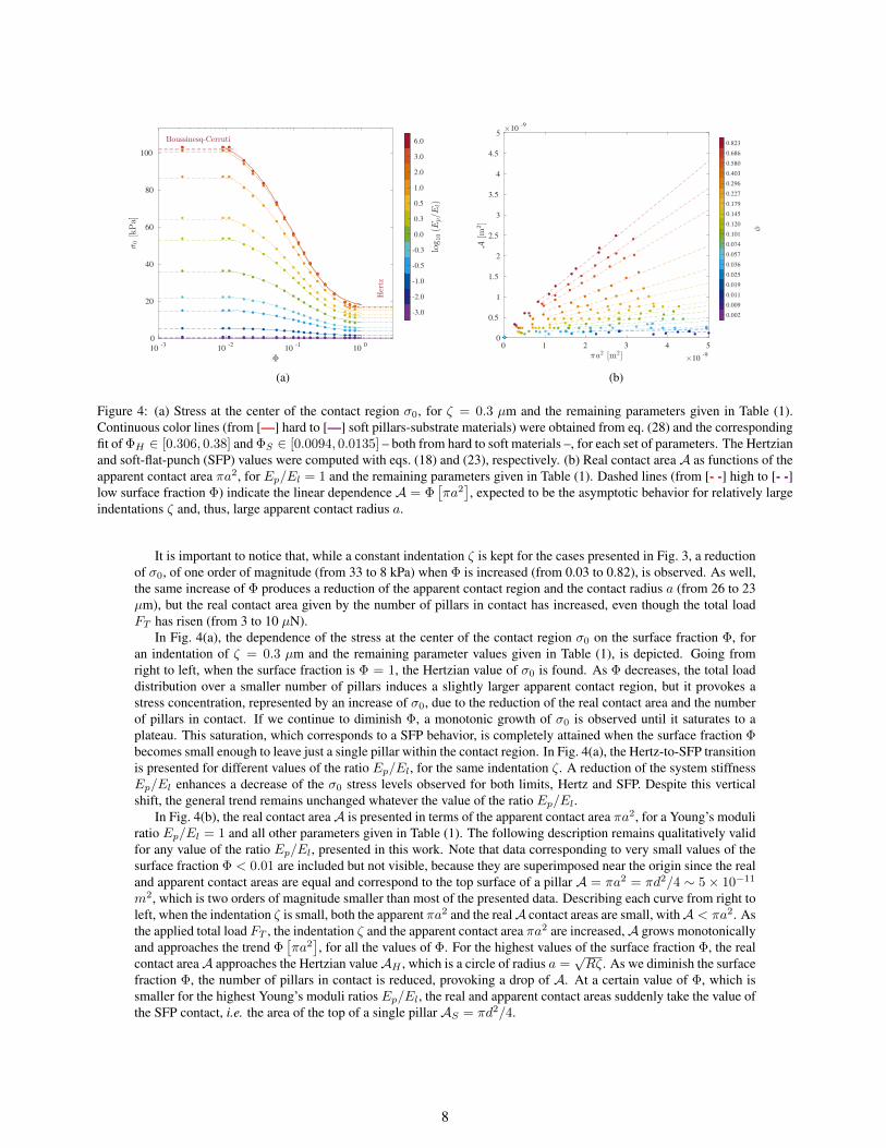
Figure 4: (a) Stress at the center of the contact region σ0, for ζ = 0.3 µm and the remaining parameters given in Table (1).Continuous color lines (from [—] hard to [—] soft pillars-substrate materials) were obtained from eq. (28) and the correspondingfit of ΦH ∈ [0.306, 0.38] and ΦS ∈ [0.0094, 0.0135] – both from hard to soft materials –, for each set of parameters. The Hertzianand soft-flat-punch (SFP) values were computed with eqs. (18) and (23), respectively. (b) Real contact areaA as functions of theapparent contact area πa2, for Ep/El = 1 and the remaining parameters given in Table (1). Dashed lines (from [- -] high to [- -]low surface fraction Φ) indicate the linear dependence A = Φ
[πa2], expected to be the asymptotic behavior for relatively large
indentations ζ and, thus, large apparent contact radius a.
It is important to notice that, while a constant indentation ζ is kept for the cases presented in Fig. 3, a reductionof σ0, of one order of magnitude (from 33 to 8 kPa) when Φ is increased (from 0.03 to 0.82), is observed. As well,the same increase of Φ produces a reduction of the apparent contact region and the contact radius a (from 26 to 23µm), but the real contact area given by the number of pillars in contact has increased, even though the total loadFT has risen (from 3 to 10 µN).
In Fig. 4(a), the dependence of the stress at the center of the contact region σ0 on the surface fraction Φ, foran indentation of ζ = 0.3 µm and the remaining parameter values given in Table (1), is depicted. Going fromright to left, when the surface fraction is Φ = 1, the Hertzian value of σ0 is found. As Φ decreases, the total loaddistribution over a smaller number of pillars induces a slightly larger apparent contact region, but it provokes astress concentration, represented by an increase of σ0, due to the reduction of the real contact area and the numberof pillars in contact. If we continue to diminish Φ, a monotonic growth of σ0 is observed until it saturates to aplateau. This saturation, which corresponds to a SFP behavior, is completely attained when the surface fraction Φbecomes small enough to leave just a single pillar within the contact region. In Fig. 4(a), the Hertz-to-SFP transitionis presented for different values of the ratio Ep/El, for the same indentation ζ. A reduction of the system stiffnessEp/El enhances a decrease of the σ0 stress levels observed for both limits, Hertz and SFP. Despite this verticalshift, the general trend remains unchanged whatever the value of the ratio Ep/El.
In Fig. 4(b), the real contact areaA is presented in terms of the apparent contact area πa2, for a Young’s moduliratio Ep/El = 1 and all other parameters given in Table (1). The following description remains qualitatively validfor any value of the ratio Ep/El, presented in this work. Note that data corresponding to very small values of thesurface fraction Φ < 0.01 are included but not visible, because they are superimposed near the origin since the realand apparent contact areas are equal and correspond to the top surface of a pillar A = πa2 = πd2/4 ∼ 5× 10⁻¹¹
m2, which is two orders of magnitude smaller than most of the presented data. Describing each curve from right toleft, when the indentation ζ is small, both the apparent πa2 and the realA contact areas are small, withA < πa2. Asthe applied total load FT , the indentation ζ and the apparent contact area πa2 are increased,A grows monotonicallyand approaches the trend Φ
[πa2], for all the values of Φ. For the highest values of the surface fraction Φ, the real
contact areaA approaches the Hertzian valueAH , which is a circle of radius a =√Rζ. As we diminish the surface
fraction Φ, the number of pillars in contact is reduced, provoking a drop of A. At a certain value of Φ, which issmaller for the highest Young’s moduli ratios Ep/El, the real and apparent contact areas suddenly take the value ofthe SFP contact, i.e. the area of the top of a single pillar AS = πd2/4.
8
5 Asymptotic casesThere are special situations for which the size of the contact region, the contact radius a, can be predicted analyt-ically. They correspond to the two limiting cases of the surface fraction, which are depicted in Fig. 1: Φ → 1 forHertzian and Φ→ 0 for soft-flat-punch contact. Both behaviors are briefly described in the following subsections.
5.1 Hertzian contactHertzian contact [1] occurs either when Φ→ 1 or when the contact radius is a� d/2. Under these conditions, theproblem simplifies to an axisymmetric geometry for which the pillar array becomes a layer of finite thickness [41].Considering infinite friction between the two bodies, the well-known stress field for Hertzian contact reads:
σ (r) = σ0H
√1−
( ra
)2, (17)
where the contact radius is a =√ζR, and the stress magnitude σ0H , perceived at the center of the contact region
r = 0, is computed from the total indentation ζ as follows:
σ0H =2
π [γl + γs]
√ζ
R. (18)
Therefore, since the pillars/substrate had become a single entity, σ0H is equally sensitive to a change in stiffness ofany component of the system (lens and compound substrate). In addition, as it is explicitly indicated in eq.(18), alarger value of the stress σ0H is expected when an important indentation ζ is imposed. It is also well-known thatthe total force is FT = (2π/3)Rζσ0H .
5.2 Soft-flat-punch contactWhen Φ → 0, a soft-flat-punch elastic contact is observed, since only one pillar is in contact with the lens. Inthe case where Ep � El, we can consider that the pillars/substrate system is rigid δ0 = ws (r, θ) = 0 and, ifthe top of the pillar is completely in contact with the lens a = d/2, the problem is described by a uniform normaldisplacement generated with a rigid flat punch [35, 1, 36]. The solution for the aforementioned problem correspondsto the superposition of the SFP solution, within a circular region at which uniform displacement is imposed. Thissituation, for which the well-known stress field reads:
σ (r) = σ0S (Ep→∞)
[1−
(2r
d
)2]−1/2
, (19)
is valid for the lens-pillar-substrate system only for a total indentation ζ that is smaller than the pillar height h.Herein, the stress magnitude σ0S (Ep→∞) at r = 0, the center of the pillar, is computed from the total indentationζ as follows:
σ0S (Ep→∞) =2ζ
πdγf. (20)
In contrast, the case for which Ep ' El does not presents an analytical model, and must be studied numeri-cally [37]. Here-in, we will name this case “soft-flat-punch” contact problem, for which we propose the followingsimple model. Considering that the total indentation ζ equals the addition wl (0, θ) + ws (0, θ) + δ0, and the ex-pressions F0 = πd2σ0S/2 and wl,s (0, θ) = πdγl,sσ0S/2,which come from the rigid-flat-punch solution (the latterby making ζ = wl,s (0, θ) and σ0S (Ep→∞) = σ0S in eq.(20)), and that the compression of the center pillar isδ0 = 4hF0/
(πd2Ep
), we can write:
ζ ≈ πd
2
[γl + γs +
4h
πdEp
]σ0S . (21)
This relationship resembles a combination of springs in series, which configuration is described by an effectiveelastic parameter γ∗ constructed as follows:
γ∗ ≈1− ν2fEl
1 +
[1− ν2s1− ν2l
]ElEs
+4hEl
πd[1− ν2f
]Ep
. (22)
9
10-6
10-3
100
103
El/Ep
0
0.25
0.5
0.75
1
σ0B/σ0B(E
c→
∞)
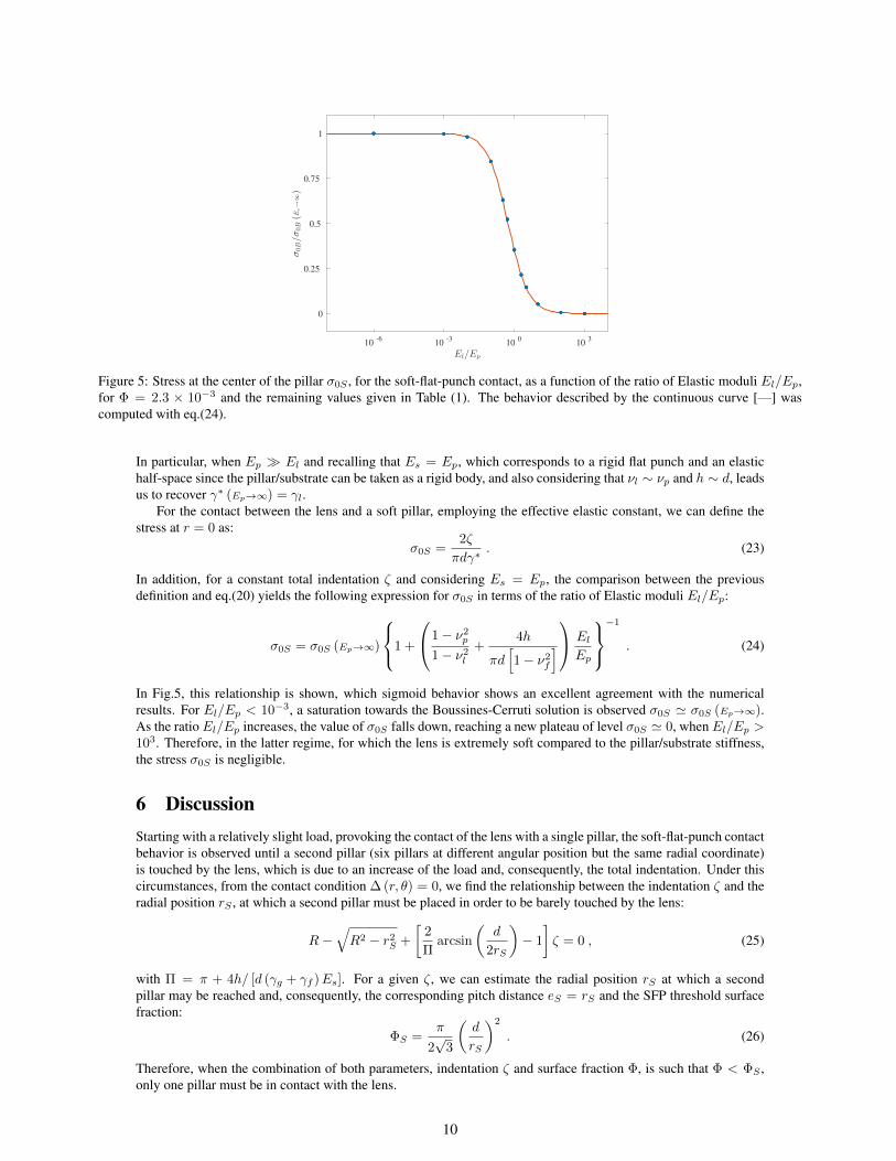
Figure 5: Stress at the center of the pillar σ0S , for the soft-flat-punch contact, as a function of the ratio of Elastic moduli El/Ep,for Φ = 2.3 × 10⁻³ and the remaining values given in Table (1). The behavior described by the continuous curve [—] wascomputed with eq.(24).
In particular, when Ep � El and recalling that Es = Ep, which corresponds to a rigid flat punch and an elastichalf-space since the pillar/substrate can be taken as a rigid body, and also considering that νl ∼ νp and h ∼ d, leadsus to recover γ∗ (Ep→∞) = γl.
For the contact between the lens and a soft pillar, employing the effective elastic constant, we can define thestress at r = 0 as:
σ0S =2ζ
πdγ∗. (23)
In addition, for a constant total indentation ζ and considering Es = Ep, the comparison between the previousdefinition and eq.(20) yields the following expression for σ0S in terms of the ratio of Elastic moduli El/Ep:
σ0S = σ0S (Ep→∞)
1 +
1− ν2p
1− ν2l+
4h
πd[1− ν2f
]
ElEp
−1
. (24)
In Fig.5, this relationship is shown, which sigmoid behavior shows an excellent agreement with the numericalresults. For El/Ep < 10−3, a saturation towards the Boussines-Cerruti solution is observed σ0S ' σ0S (Ep→∞).As the ratio El/Ep increases, the value of σ0S falls down, reaching a new plateau of level σ0S ' 0, when El/Ep >103. Therefore, in the latter regime, for which the lens is extremely soft compared to the pillar/substrate stiffness,the stress σ0S is negligible.
6 DiscussionStarting with a relatively slight load, provoking the contact of the lens with a single pillar, the soft-flat-punch contactbehavior is observed until a second pillar (six pillars at different angular position but the same radial coordinate)is touched by the lens, which is due to an increase of the load and, consequently, the total indentation. Under thiscircumstances, from the contact condition ∆ (r, θ) = 0, we find the relationship between the indentation ζ and theradial position rS , at which a second pillar must be placed in order to be barely touched by the lens:
R−√R2 − r2S +
[2
Πarcsin
(d
2rS
)− 1
]ζ = 0 , (25)
with Π = π + 4h/ [d (γg + γf )Es]. For a given ζ, we can estimate the radial position rS at which a secondpillar may be reached and, consequently, the corresponding pitch distance eS = rS and the SFP threshold surfacefraction:
ΦS =π
2√
3
(d
rS
)2
. (26)
Therefore, when the combination of both parameters, indentation ζ and surface fraction Φ, is such that Φ < ΦS ,only one pillar must be in contact with the lens.
10
0.5 1 1.5 2 2.5 3 3.5 4 4.5
Φ∗
0
0.1
0.2
0.3
0.4
0.5
0.6
0.7
0.8
0.9
1
σ∗ 0
Φ=
ΦB
Φ=
ΦH
0.025
0.050
0.075
0.100
0.125
0.150
0.175
0.200
0.225
0.250
ζ/h
(a)
10-3
10-2
10-1
100
Φ
10-2
10-1
100
A∗
0.025
0.050
0.075
0.100
0.125
0.150
0.175
0.200
0.225
0.250
ζ/h
(b)
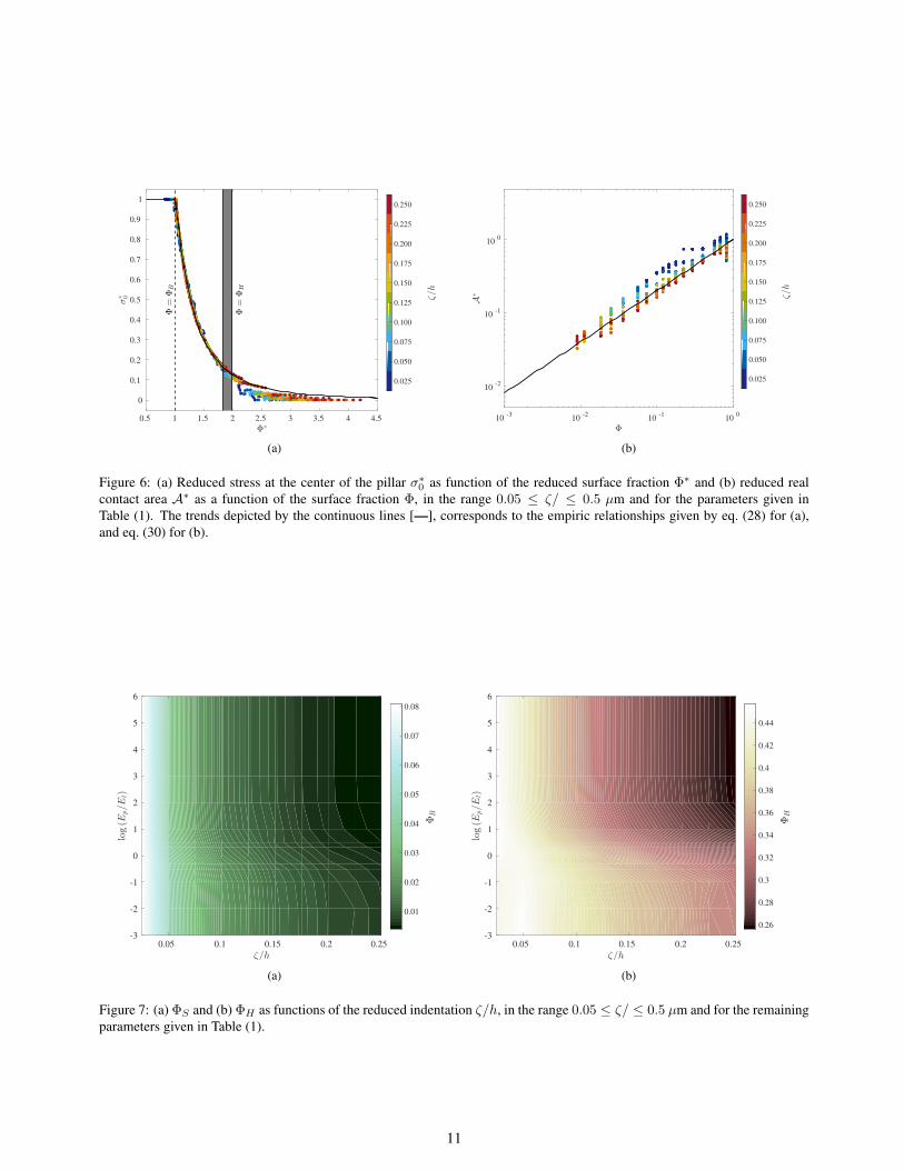
Figure 6: (a) Reduced stress at the center of the pillar σ∗0 as function of the reduced surface fraction Φ∗ and (b) reduced realcontact area A∗ as a function of the surface fraction Φ, in the range 0.05 ≤ ζ/ ≤ 0.5 µm and for the parameters given inTable (1). The trends depicted by the continuous lines [—], corresponds to the empiric relationships given by eq. (28) for (a),and eq. (30) for (b).
0.05 0.1 0.15 0.2 0.25
ζ/h
-3
-2
-1
0
1
2
3
4
5
6
log(E
p/E
l)
0.01
0.02
0.03
0.04
0.05
0.06
0.07
0.08
ΦB
(a)
0.05 0.1 0.15 0.2 0.25
ζ/h
-3
-2
-1
0
1
2
3
4
5
6
log(E
p/E
l)
0.26
0.28
0.3
0.32
0.34
0.36
0.38
0.4
0.42
0.44
ΦH
(b)
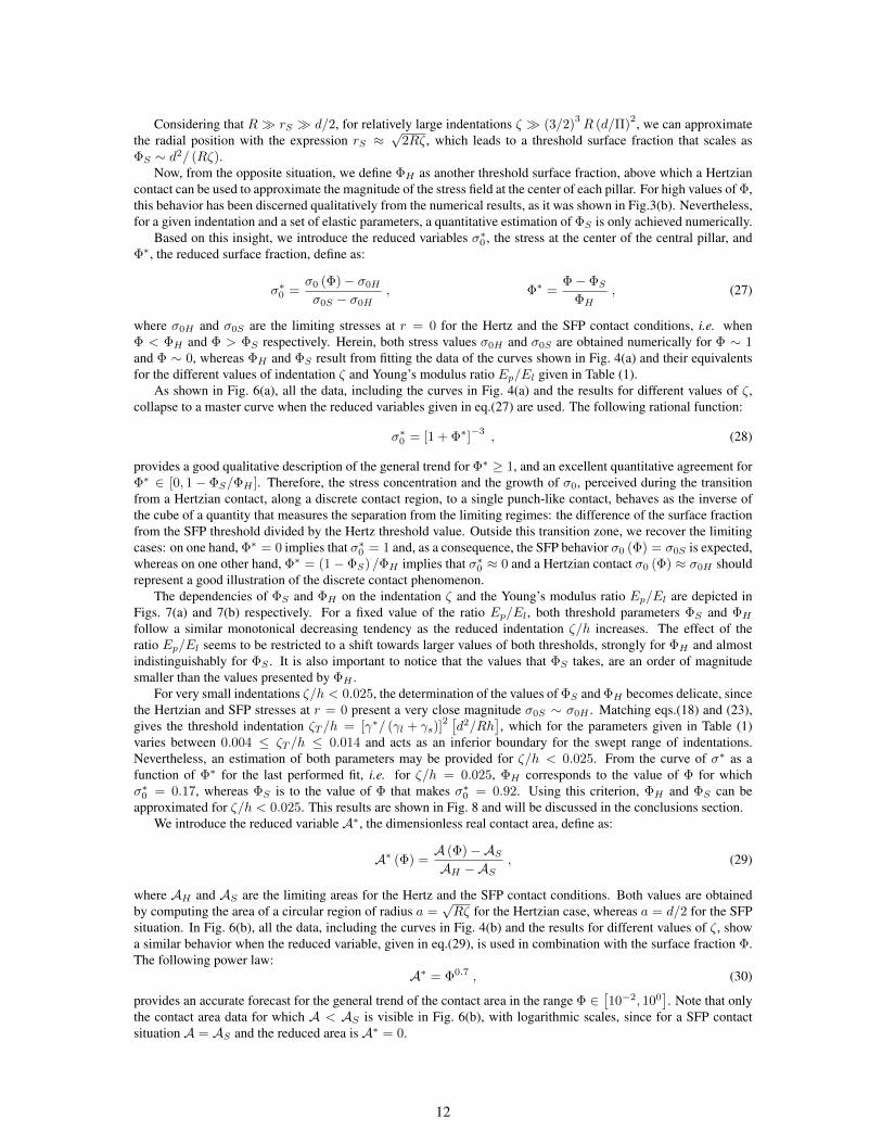
Figure 7: (a) ΦS and (b) ΦH as functions of the reduced indentation ζ/h, in the range 0.05 ≤ ζ/ ≤ 0.5 µm and for the remainingparameters given in Table (1).
11
Considering that R � rS � d/2, for relatively large indentations ζ � (3/2)3R (d/Π)
2, we can approximatethe radial position with the expression rS ≈
√2Rζ, which leads to a threshold surface fraction that scales as
ΦS ∼ d2/ (Rζ).Now, from the opposite situation, we define ΦH as another threshold surface fraction, above which a Hertzian
contact can be used to approximate the magnitude of the stress field at the center of each pillar. For high values of Φ,this behavior has been discerned qualitatively from the numerical results, as it was shown in Fig.3(b). Nevertheless,for a given indentation and a set of elastic parameters, a quantitative estimation of ΦS is only achieved numerically.
Based on this insight, we introduce the reduced variables σ∗0 , the stress at the center of the central pillar, andΦ∗, the reduced surface fraction, define as:
σ∗0 =σ0 (Φ)− σ0Hσ0S − σ0H
, Φ∗ =Φ− ΦS
ΦH, (27)
where σ0H and σ0S are the limiting stresses at r = 0 for the Hertz and the SFP contact conditions, i.e. whenΦ < ΦH and Φ > ΦS respectively. Herein, both stress values σ0H and σ0S are obtained numerically for Φ ∼ 1and Φ ∼ 0, whereas ΦH and ΦS result from fitting the data of the curves shown in Fig. 4(a) and their equivalentsfor the different values of indentation ζ and Young’s modulus ratio Ep/El given in Table (1).
As shown in Fig. 6(a), all the data, including the curves in Fig. 4(a) and the results for different values of ζ,collapse to a master curve when the reduced variables given in eq.(27) are used. The following rational function:
σ∗0 = [1 + Φ∗]−3 , (28)
provides a good qualitative description of the general trend for Φ∗ ≥ 1, and an excellent quantitative agreement forΦ∗ ∈ [0, 1− ΦS/ΦH ]. Therefore, the stress concentration and the growth of σ0, perceived during the transitionfrom a Hertzian contact, along a discrete contact region, to a single punch-like contact, behaves as the inverse ofthe cube of a quantity that measures the separation from the limiting regimes: the difference of the surface fractionfrom the SFP threshold divided by the Hertz threshold value. Outside this transition zone, we recover the limitingcases: on one hand, Φ∗ = 0 implies that σ∗0 = 1 and, as a consequence, the SFP behavior σ0 (Φ) = σ0S is expected,whereas on one other hand, Φ∗ = (1− ΦS) /ΦH implies that σ∗0 ≈ 0 and a Hertzian contact σ0 (Φ) ≈ σ0H shouldrepresent a good illustration of the discrete contact phenomenon.
The dependencies of ΦS and ΦH on the indentation ζ and the Young’s modulus ratio Ep/El are depicted inFigs. 7(a) and 7(b) respectively. For a fixed value of the ratio Ep/El, both threshold parameters ΦS and ΦHfollow a similar monotonical decreasing tendency as the reduced indentation ζ/h increases. The effect of theratio Ep/El seems to be restricted to a shift towards larger values of both thresholds, strongly for ΦH and almostindistinguishably for ΦS . It is also important to notice that the values that ΦS takes, are an order of magnitudesmaller than the values presented by ΦH .
For very small indentations ζ/h < 0.025, the determination of the values of ΦS and ΦH becomes delicate, sincethe Hertzian and SFP stresses at r = 0 present a very close magnitude σ0S ∼ σ0H . Matching eqs.(18) and (23),gives the threshold indentation ζT /h = [γ∗/ (γl + γs)]
2 [d2/Rh
], which for the parameters given in Table (1)
varies between 0.004 ≤ ζT /h ≤ 0.014 and acts as an inferior boundary for the swept range of indentations.Nevertheless, an estimation of both parameters may be provided for ζ/h < 0.025. From the curve of σ∗ as afunction of Φ∗ for the last performed fit, i.e. for ζ/h = 0.025, ΦH corresponds to the value of Φ for whichσ∗0 = 0.17, whereas ΦS is to the value of Φ that makes σ∗0 = 0.92. Using this criterion, ΦH and ΦS can beapproximated for ζ/h < 0.025. This results are shown in Fig. 8 and will be discussed in the conclusions section.
We introduce the reduced variable A∗, the dimensionless real contact area, define as:
A∗ (Φ) =A (Φ)−ASAH −AS
, (29)
where AH and AS are the limiting areas for the Hertz and the SFP contact conditions. Both values are obtainedby computing the area of a circular region of radius a =
√Rζ for the Hertzian case, whereas a = d/2 for the SFP
situation. In Fig. 6(b), all the data, including the curves in Fig. 4(b) and the results for different values of ζ, showa similar behavior when the reduced variable, given in eq.(29), is used in combination with the surface fraction Φ.The following power law:
A∗ = Φ0.7 , (30)
provides an accurate forecast for the general trend of the contact area in the range Φ ∈[10−2, 100
]. Note that only
the contact area data for which A < AS is visible in Fig. 6(b), with logarithmic scales, since for a SFP contactsituation A = AS and the reduced area is A∗ = 0.
12
10 -2 10 -1
���
10 -2
10 -1
10 0
�
� � �
��
��� � �
��������� �����
��������
����
��� � �
��
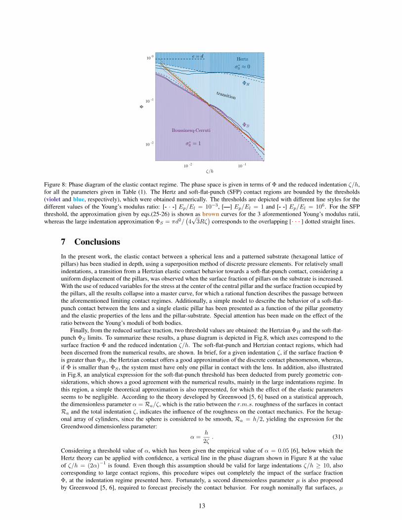
Figure 8: Phase diagram of the elastic contact regime. The phase space is given in terms of Φ and the reduced indentation ζ/h,for all the parameters given in Table (1). The Hertz and soft-flat-punch (SFP) contact regions are bounded by the thresholds(violet and blue, respectively), which were obtained numerically. The thresholds are depicted with different line styles for thedifferent values of the Young’s modulus ratio: [- · -] Ep/El = 10−3, [—] Ep/El = 1 and [- -] Ep/El = 106. For the SFPthreshold, the approximation given by eqs.(25-26) is shown as brown curves for the 3 aforementioned Young’s modulus ratii,whereas the large indentation approximation ΦS = πd2/
(4√
3Rζ)
corresponds to the overlapping [· · · ] dotted straight lines.
7 ConclusionsIn the present work, the elastic contact between a spherical lens and a patterned substrate (hexagonal lattice ofpillars) has been studied in depth, using a superposition method of discrete pressure elements. For relatively smallindentations, a transition from a Hertzian elastic contact behavior towards a soft-flat-punch contact, considering auniform displacement of the pillars, was observed when the surface fraction of pillars on the substrate is increased.With the use of reduced variables for the stress at the center of the central pillar and the surface fraction occupied bythe pillars, all the results collapse into a master curve, for which a rational function describes the passage betweenthe aforementioned limiting contact regimes. Additionally, a simple model to describe the behavior of a soft-flat-punch contact between the lens and a single elastic pillar has been presented as a function of the pillar geometryand the elastic properties of the lens and the pillar-substrate. Special attention has been made on the effect of theratio between the Young’s moduli of both bodies.
Finally, from the reduced surface traction, two threshold values are obtained: the Hertzian ΦH and the soft-flat-punch ΦS limits. To summarize these results, a phase diagram is depicted in Fig.8, which axes correspond to thesurface fraction Φ and the reduced indentation ζ/h. The soft-flat-punch and Hertzian contact regions, which hadbeen discerned from the numerical results, are shown. In brief, for a given indentation ζ, if the surface fraction Φis greater than ΦH , the Hertzian contact offers a good approximation of the discrete contact phenomenon, whereas,if Φ is smaller than ΦS , the system must have only one pillar in contact with the lens. In addition, also illustratedin Fig.8, an analytical expression for the soft-flat-punch threshold has been deducted from purely geometric con-siderations, which shows a good agreement with the numerical results, mainly in the large indentations regime. Inthis region, a simple theoretical approximation is also represented, for which the effect of the elastic parametersseems to be negligible. According to the theory developed by Greenwood [5, 6] based on a statistical approach,the dimensionless parameter α = Ra/ζ, which is the ratio between the r.m.s. roughness of the surfaces in contactRa and the total indentation ζ, indicates the influence of the roughness on the contact mechanics. For the hexag-onal array of cylinders, since the sphere is considered to be smooth, Ra = h/2, yielding the expression for theGreendwood dimensionless parameter:
α =h
2ζ. (31)
Considering a threshold value of α, which has been given the empirical value of α = 0.05 [6], below which theHertz theory can be applied with confidence, a vertical line in the phase diagram shown in Figure 8 at the valueof ζ/h = (2α)
−1 is found. Even though this assumption should be valid for large indentations ζ/h ≥ 10, alsocorresponding to large contact regions, this procedure wipes out completely the impact of the surface fractionΦ, at the indentation regime presented here. Fortunately, a second dimensionless parameter µ is also proposedby Greenwood [5, 6], required to forecast precisely the contact behavior. For rough nominally flat surfaces, µ
13

depends only on the geometry, i.e. the roughness, the asperity density and the r.m.s. curvature of the asperities,and only generates a secondary effect on the stress and displacement fields when the contact zone spans infinitelycompared to the nominal size of the asperities. For the case presented herein, we expect that µ will take the formµ ∼ Φ
√RRa/d, which leads to an estimation of the second Greenwood dimensionless parameter:
µ ∼ Φ
d
√Rh
2, (32)
where the effect of the surface fraction Φ appears directly.Thus, this analysis, which is a result of the qualitative comparison with the Greenwood’s theory, indicates that Φand ζ/h are the correct dimensionless parameters required to describe the passage from Hertzian to soft-flat-punchcontact on periodically rough surfaces.
The methodology that we have developed allowed us to gain some insight on the discrete contact phenomenon.Nevertheless, it only represents some first steps and several important issues remain to be addressed. For instance,the case of large indentations, which are comparable in size with the height of the pillars ζ ∼ h, must be analyzedseparately. Under these circumstances, an intimate contact between the lens and the patterned surface, which hasbeen studied with experiments [3, 31, 33, 42], may be triggered, and the role of adhesion should be taken intoaccount. Our efforts are currently being focused on this problem, and the corresponding analysis will be presentedin a future publication.
8 Acknowledgements and fundingWe wish to thank T. Salez for fruitful and very interesting discussions. We have no competing interests. Thisproject was carried out thanks to funding by the ANR (ANR-11-BS04-0030 project).
References[1] Johnson KL. Contact mechanics. Cambridge University Press; 1985.
[2] Restagno F, Crassous J, Cottin-Bizonne C, Charlaix E. Adhesion between weakly rough beads. Phys Rev E.2002;65(4):042301.
[3] Degrandi-Contraires E, Beaumont A, Restagno F, Weil R, Poulard C, Leger L. Cassie-Wenzel-like transition in patternedsoft elastomer adhesive contacts. Eur Phys Lett. 2013;101(14001):1–6.
[4] Greenwood JA, Williamson JBP. Contact of nominally flat surfaces. Proc R Soc Lond A. 1966;295:300–319.
[5] Greenwood JA, Tripp JH. The elastic contact of rough spheres. J Appl Mech. 1967;89:153–159.
[6] Greenwood JA, Johnson KL, Matsubara E. Surface roughness parameter in Hertz contact. Wear. 1984;100:47–57.
[7] Li L, Etsion I, Talke FE. Elastic?Plastic Spherical Contact Modeling Including Roughness Effects. Tribol Lett.2010;40:357–363.
[8] Beheshti A, Khonsari MM. On the Contact of Curved Rough Surfaces: Contact Behavior and Predictive Formulas. J ApplMech. 2014;81(111004):1–15.
[9] Bush AW, Gibson RD, Thomas TR. The elastic contact of a rough surface. Wear. 1975;35:87–111.
[10] Persson BNJ. Contact mechanics for randomly rough surfaces. Surf Sci Rep. 2006;61:201–227.
[11] Johnson KL, Greenwood JA, Higginson JG. The contact of elastic regular wavy surfaces. Int J Mech Sci. 1984;27(6):383–396.
[12] Block JM, Keer LM. Periodic contact problems in plane elasticity. J Mech Mater Struct. 2008;3(7):1207–1237.
[13] Archard JF. Contact and Rubbing of Flat Surfaces. J Appl Phys. 1953;24(981):1–8.
[14] Murarash B, Itovich Y, Varenberg M. Tuning elastomer friction by hexagonal surface patterning. Soft Matter.2011;7(12):5553–5557.
[15] Brormann K, Barel I, Urbakh M, R B. Friction on a Microstructured Elastomer Surface. Tribol Lett. 2013;50(1):3–15.
[16] Kligerman Y, Varenberg M. Elimination of Stick-Slip Motion in Sliding of Split or Rough Surface. Tribol Lett.2014;53(2):395–399.
[17] Tsipenyuk A, Varenberg M. Use of biomimetic hexagonal surface texture in friction against lubricated skin. J R SocInterface. 2014;11:1–13.
[18] Romero V, Wandersman E, Debregeas G, Prevost A. Probing Locally the Onset of Slippage at a Model MulticontactInterface. Phys Rev Lett. 2014;112(094301):1–5.
[19] Mittal KL. Polymer surface modification: Relevance to adhesion, Volume 3. CRC Press; 2004.
14

[20] Kozlova N, Santore MM. Manipulation of Micrometer-Scale Adhesion by Tuning Nanometer-Scale Surface Features.Langmuir. 2006;22(3):1135–1142.
[21] Poulard C, Restagno F, Weil R, Leger L. Mechanical tuning of adhesion through micro-patterning of elastic surfaces. SoftMatter. 2011;101(7):2543–2551.
[22] Tamelier J, Chary S, Turner KL. Vertical Anisotropic Microfibers for a Gecko-Inspired Adhesive. Langmuir.2012;28(23):8746–8752.
[23] Gorb S, Varenberg M, Peressadko A, Tuma J. Biomimetic mushroom-shaped fibrillar adhesive microstructure. Journal ofThe Royal Society Interface. 2007;4(13):271–275.
[24] Bhushan B, Jung YC. Natural and biomimetic artificial surfaces for superhydrophobicity, self-cleaning, low adhesion, anddrag reduction. Progress in Materials Science. 2011;56(1):1–108.
[25] Hui CY, Glassmaker N, Tang T, Jagota A. Design of biomimetic fibrillar interfaces: 2. Mechanics of enhanced adhesion.Journal of The Royal Society Interface. 2004;1(1):35–48.
[26] Zhou M, Pesika N, Zeng H, Tian Y, Israelachvili J. Recent advances in gecko adhesion and friction mechanisms anddevelopment of gecko-inspired dry adhesive surfaces. Friction. 2013;1(2):114–129.
[27] Crosby AJ, Hageman M, Duncan A. Controlling polymer adhesion with “pancakes”. Langmuir. 2005;21(25):11738–11743.
[28] Murphy MP, Kim S, Sitti M. Enhanced adhesion by gecko-inspired hierarchical fibrillar adhesives. ACS applied materials& interfaces. 2009;1(4):849–855.
[29] Benz M, Rosenberg KJ, Kramer EJ, Israelachvili JN. The deformation and adhesion of randomly rough and patternedsurfaces. The Journal of Physical Chemistry B. 2006;110(24):11884–11893.
[30] Greiner C, del Campo A, Arzt E. Adhesion of bioinspired micropatterned surfaces: effects of pillar radius, aspect ratio,and preload. Langmuir. 2007;23(7):3495–3502.
[31] Verneuil E, Ladoux B, Buguin A, Silberzan P. Adhesion on microstructured surfaces. J Adhesion. 2007;83:449–472.
[32] Hisler V, Palmieri M, Le Houerou V, Gauthier C, Nardin M, Vallat MF, et al. Scale invariance of the contact mechanics ofmicropatterned elastic substrates. Int J Adhesion Adhesives. 2013;45:144–149.
[33] Nadermann N, Ning J, Jagota A, Hui CY. Active switching of adhesion in a film-terminated fibrillar structure. Langmuir.2010;26(19):15464–15471.
[34] Love AEH. A treatise on the mathematical theory of elasticity. 4th ed. Cambridge University Press; 1952.
[35] Harding JW, Sneddon IN. The elastic stresses produced by the indentation of the plane surface of a semi-infinite elasticsolid by a rigid punch. Math Proc Cambridge. 1945;41(1):16–26.
[36] Maugis D. Contact, adhesion and rupture of elastic solids. Springer; 1999.
[37] Gecit MR. Axisymmetric contact problem for a semi-infinite cylinder and a half space. Int J Engng Sci. 1986;24(8):1245–1256.
[38] See Supplemental Material at [URL will be inserted by publisher] for details on the numerical method;.
[39] Guidoni GM, Schillo D, Hangen U, Castellanos G, Arzt E, McMeeking RM, et al. Discrete contact mechanics of a fibrillarsurface with backing layer interactions. J Mech Phys Solids. 2010;58:1571–1581.
[40] Noderer WL, Shen L, Vajpayee S, Glassmaker NJ, Jagota A, Hui CY. Enhanced adhesion and compliance of film-terminated fibrillar surfaces. Proc R Soc A. 2007;463:2631–2654.
[41] Li J, Chou TW. Elastic field of a thin-film/substrate system under an axisymmetric loading. Int J Solids Struct. 1997;34(35–36):4463–4478.
[42] Dies L, Restagno F, Weil R, Leger L, Poulard C. Role of adhesion between asperities in the formation of elastic solid/solidcontacts. Eur Phys J E. 2015;38(130):1–8.
15
Supplementary material of the paper:
Stress concentration in periodically rough hertzian contact: Hertz tosoft-flat-punch transition
Rene Ledesma-Alonso1,2,† , Elie Raphael1, Liliane Leger2, Frederic Restagno2, and Christophe Poulard2
1Laboratoire de Physico-Chimie Theorique, UMR CNRS 7083 Gulliver, ESPCI ParisTech, PSL ResearchUniversity, 10 Rue Vauquelin, 75005 Paris, France
2Laboratoire de Physique des Solides, CNRS, Univ. Paris-Sud, Universite Paris-Saclay, 91400 Orsay,France
†e-mail: [email protected]
July 4, 2016
1 Pillar array and symmetry
At the substrate, each cylindrical pillar is fixed and placed at the intersection of two lines, the first described by thefunction y = −
√3 [x− n e] and the second by y =
[√3/2]me, where n and m are integers that enumerate each
of the lines, as shown in Fig. 1(a), and e is the pitch distance between pillars. Thus, the center of the nm-pillar isplaced at the coordinates xnm = [2n−m] e/2 and ynm =
√3me/2. In addition, since the spherical lens is centered
above the center of the n = m = 0 pillar and due to the symmetry of a hexagonal pillar lattice, which has 6 rotationsymmetries and 6 reflection symmetries, the primitive cell of our system is a circular sector with central angle π/6.The primitive cell is also shown in Fig. 1(a). As a consequence, the ranges of the indices n and m are coupled andrestricted to n ∈ [0, N ] and m ∈ [0,M ], and we must also take into account two new indices u and k, which are alsorestricted to u ∈ [0, 5] and k ∈ [0,K], and stand for the aforementioned symmetries of the system. The value of Nis strictly related to the contact radius, whereas M depends on the index n and K depends on both indices n and m,which relationships are given in Table 1.
n M (n) m K (n,m)
n < 2 0 0n = 2 1 0
n > 2 & odd (n− 1) /2 0 01 ≤ m ≤M 1
n > 2 & even n/2 0 01 ≤ m ≤M − 1 1
M 0
Table 1: Ranges of the indices n and m, and their relationship with the limit values M and K, depending on n and m.
1
arX
iv:1
604.
0016
6v2
[co
nd-m
at.m
trl-
sci]
1 J
ul 2
016
n=0
n=1
n=2
n=3
n=4
m = 4
m = 3
m = 2
m = 1
m = 0
M=
j n2
k
k = 0u = 0
k = 1u = 1
(a)
rnm✓
r %
'
✓nmuk 2⇡ � �nmuk
⇢nm
uk
(b)
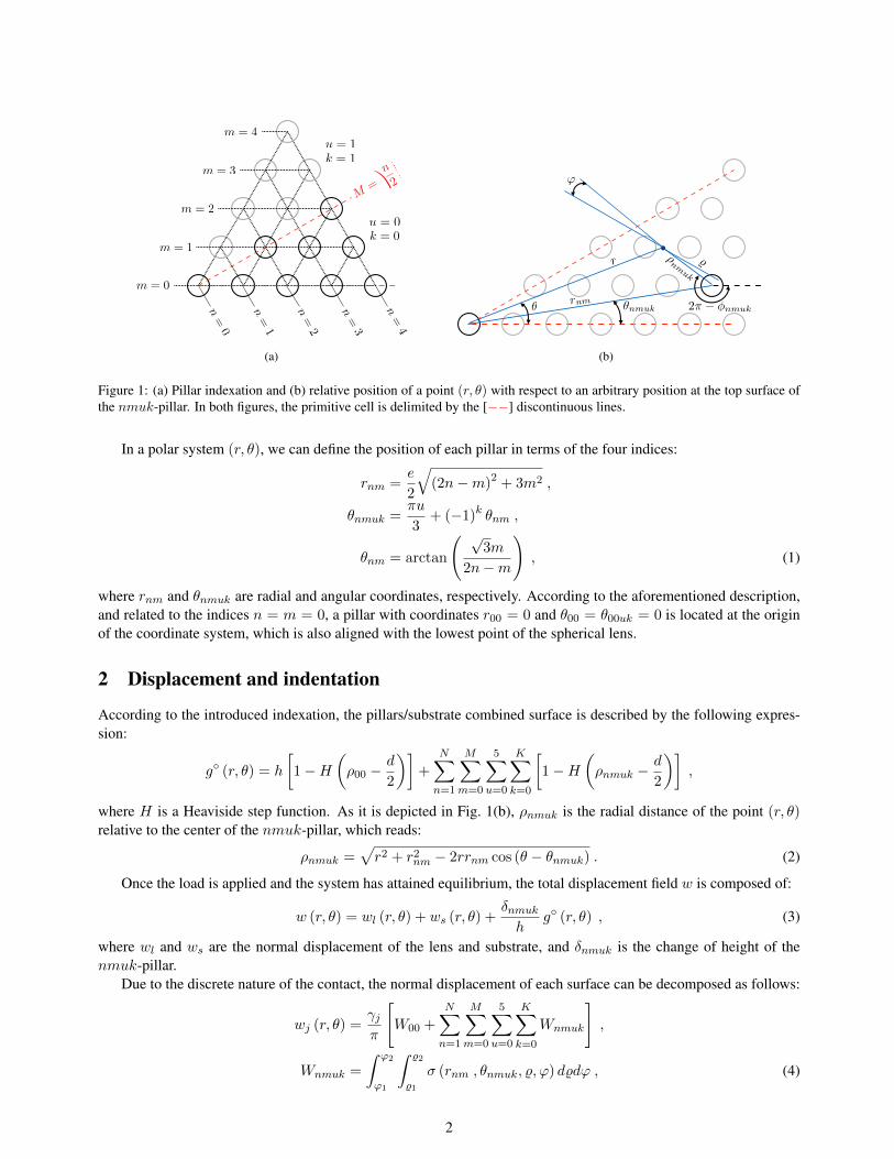
Figure 1: (a) Pillar indexation and (b) relative position of a point (r, θ) with respect to an arbitrary position at the top surface ofthe nmuk-pillar. In both figures, the primitive cell is delimited by the [−−] discontinuous lines.
In a polar system (r, θ), we can define the position of each pillar in terms of the four indices:
rnm =e
2
√(2n−m)2 + 3m2 ,
θnmuk =πu
3+ (−1)k θnm ,
θnm = arctan
( √3m
2n−m
), (1)
where rnm and θnmuk are radial and angular coordinates, respectively. According to the aforementioned description,and related to the indices n = m = 0, a pillar with coordinates r00 = 0 and θ00 = θ00uk = 0 is located at the originof the coordinate system, which is also aligned with the lowest point of the spherical lens.
2 Displacement and indentation
According to the introduced indexation, the pillars/substrate combined surface is described by the following expres-sion:
g◦ (r, θ) = h
[1−H
(ρ00 −
d
2
)]+
N∑
n=1
M∑
m=0
5∑
u=0
K∑
k=0
[1−H
(ρnmuk −
d
2
)],
where H is a Heaviside step function. As it is depicted in Fig. 1(b), ρnmuk is the radial distance of the point (r, θ)relative to the center of the nmuk-pillar, which reads:
ρnmuk =√r2 + r2nm − 2rrnm cos (θ − θnmuk) . (2)
Once the load is applied and the system has attained equilibrium, the total displacement field w is composed of:
w (r, θ) = wl (r, θ) + ws (r, θ) +δnmukh
g◦ (r, θ) , (3)
where wl and ws are the normal displacement of the lens and substrate, and δnmuk is the change of height of thenmuk-pillar.
Due to the discrete nature of the contact, the normal displacement of each surface can be decomposed as follows:
wj (r, θ) =γjπ
[W00 +
N∑
n=1
M∑
m=0
5∑
u=0
K∑
k=0
Wnmuk
],
Wnmuk =
∫ ϕ2
ϕ1
∫ %2
%1
σ (rnm , θnmuk, %, ϕ) d%dϕ , (4)
2
where j = l, s refers to the lens or substrate, Wnmuk is the reduced displacement due to the contact with the nmuk-pillar, for the center pillar W00 = W00uk and (%, ϕ) are the relative coordinates of the center of the nmuk-pillar withrespect to the point (r, θ), as shown in Fig. 1(b).
Also owing to the symmetry of the system, the change of height becomes δnm = δnmuk, and since the compressionof the nmuk-pillar is approximated by the Hooke’s law, it is equal to:
δnm =4h
πd2EpFnm . (5)
In turn, the lens and substrate indentations are given by the corresponding displacements at the origin r = 0, thusζl,s = wl,s (0, θ), and the total indentation ζ corresponds to:
ζ = ζl + ζs + δ00 . (6)
The total load is obtained by adding the contribution of each pillar as follows:
FT = F00 + 6N∑
n=1
M∑
m=0
K∑
k=0
Fnm0k , (7)
where Fnm = Fnmuk is the load exerted over the nmuk-pillar in the contact region, which reads:
Fnm =
∫ 2π
0
∫ d/2
0σ (rnm, θnm, ρ, φ) ρdρdφ , (8)
whereas ρ = ρnmuk and φ = φnmuk represent the radial and angular coordinates at the surface of the nmuk-pillar,relative to the pillar center (rnm, θnmuk) and restricted to the ranges ρ ∈ [0, d/2] and φ ∈ [0, 2π]. In order totransform σ (r, θ) into σ (rnm, θnmuk, ρ, φ), one should express r and θ for a given relative position (ρ, φ) and a pillar(rnm, θnmuk) using the following expressions:
r =√ρ2 + r2nm + 2ρrnm cos (φ− θnmuk) ,
θ = arcsin
(ρ sin (π − φ) + rnm sin (θnmuk)
r
), (9)
which are deduced form Fig.1(b).Finally, at the local contact region of each pillar, we have ∆ (r, θ) = 0 and G (r, θ) = 1, and thus the total
displacement field w is related to the total indentation ζ as follows:
w (r, θ) = ζ −[R−
√R2 − r2
]. (10)
By imposing a total indentation in eq.(10), and gathering the displacement contributions given in eqs. (4) and (5) toassemble eq.(3), the stress field σ at the contact region, i.e. the top of the pillars by taking G (r, θ) = 1, is recoverednumerically using a superposition method of discrete pressure elements, which is detailed in section 3.
3 Discrete pressure elements
We will now introduce the variable q, defined as:
q = −1 +
N∑
n=0
M∑
n=0
{1−H
(rnm −
[a+
d
2
])}, (11)
where H is a Heaviside step function, and the new variable presents the range q ∈ [0, Q]. This variable allows us tocount the total number of pillars Q within the contact region, and to transform the double finite series into a singleseries:
N∑
n=0
M∑
n=0
→Q∑
q=0
andN∑
n=1
M∑
n=0
→Q∑
q=1
, (12)
3
b
−5
−4
−3
−2
−1
0
1
2
3
4
5
0 1 2 3 4 5 6 7 8 9 10
(rnm, θnmuk)
t
px
py 0 1 2 3 4 5 6 7 8 9 10
11 12 13 14 15 16 17 18 19 20 2122 23 24 25 26 27 28 29 30 31 32
33 34 35 36 37 38 39 40 41
42 43 44 45 46 47 4849 50 51 52 53
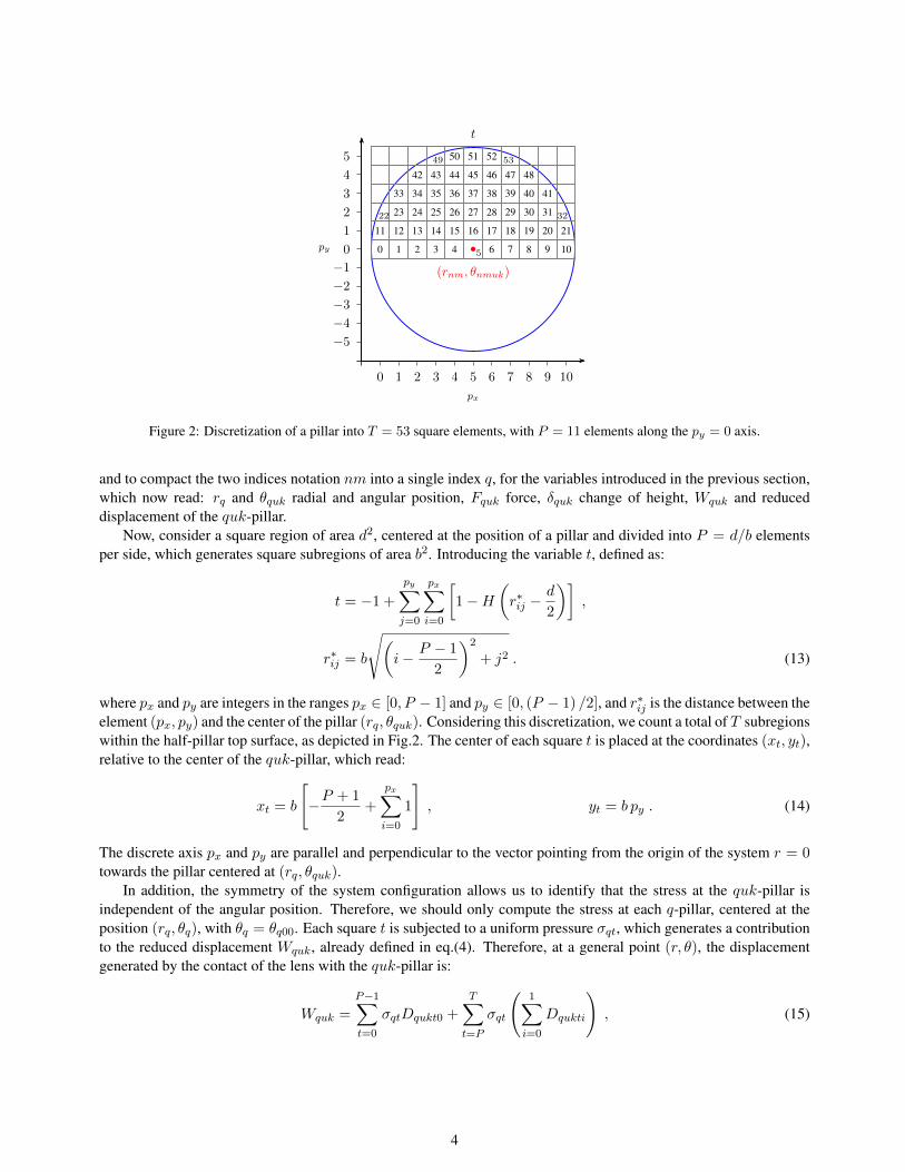
Figure 2: Discretization of a pillar into T = 53 square elements, with P = 11 elements along the py = 0 axis.
and to compact the two indices notation nm into a single index q, for the variables introduced in the previous section,which now read: rq and θquk radial and angular position, Fquk force, δquk change of height, Wquk and reduceddisplacement of the quk-pillar.
Now, consider a square region of area d2, centered at the position of a pillar and divided into P = d/b elementsper side, which generates square subregions of area b2. Introducing the variable t, defined as:
t = −1 +
py∑
j=0
px∑
i=0
[1−H
(r∗ij −
d
2
)],
r∗ij = b
√(i− P − 1
2
)2
+ j2 . (13)
where px and py are integers in the ranges px ∈ [0, P − 1] and py ∈ [0, (P − 1) /2], and r∗ij is the distance between theelement (px, py) and the center of the pillar (rq, θquk). Considering this discretization, we count a total of T subregionswithin the half-pillar top surface, as depicted in Fig.2. The center of each square t is placed at the coordinates (xt, yt),relative to the center of the quk-pillar, which read:
xt = b
[−P + 1
2+
px∑
i=0
1
], yt = b py . (14)
The discrete axis px and py are parallel and perpendicular to the vector pointing from the origin of the system r = 0towards the pillar centered at (rq, θquk).
In addition, the symmetry of the system configuration allows us to identify that the stress at the quk-pillar isindependent of the angular position. Therefore, we should only compute the stress at each q-pillar, centered at theposition (rq, θq), with θq = θq00. Each square t is subjected to a uniform pressure σqt, which generates a contributionto the reduced displacement Wquk, already defined in eq.(4). Therefore, at a general point (r, θ), the displacementgenerated by the contact of the lens with the quk-pillar is:
Wquk =
P−1∑
t=0
σqtDqukt0 +
T∑
t=P
σqt
(1∑
i=0
Dqukti
), (15)
4
where the function D is defined [1, 2] as:
Dqukti =
2∑
j=1
[X + (−1)j
b
2
]ln
[Y + (−1)j
b
2
]+
√[Y + (−1)j
b
2
]2+
[X + (−1)j
b
2
]2
[Y − (−1)j
b
2
]+
√[Y − (−1)j
b
2
]2+
[X + (−1)j
b
2
]2
+
[Y + (−1)j
b
2
]ln
[X + (−1)j
b
2
]+
√[Y + (−1)j
b
2
]2+
[X + (−1)j
b
2
]2
[X − (−1)j
b
2
]+
√[Y + (−1)j
b
2
]2+
[X − (−1)j
b
2
]2
,
(16)
with:
X =
∣∣∣∣rq + xt − r cos (θquk − θ)∣∣∣∣ , Y =
∣∣∣∣ (−1)i yt + r sin (θquk − θ)∣∣∣∣ . (17)
At the contact between the lens and the quk-pillar, the exerted mutual load is calculated from the sum:
F (rq, θquk) = b2
[P−1∑
t=0
σqt + 2T∑
t=P
σqt
]. (18)
From eq.(3), the addition of the pillar height change and the displacements of the lens and the substrate gives thetotal displacement, which reads:
w (r, θ) =4h
πEp
(b
d
)2
[1−H
(r − d
2
)][P−1∑
t=0
σqt + 2T∑
t=P
σqt
]
+
Q∑
q=1
5∑
u=0
K∑
k=0
[1−H
(ρquk −
d
2
)][P−1∑
t=0
σqt + 2T∑
t=P
σqt
]
+
(γl + γsπ
)
T∑
t=1
σ0tD000t0 +
Q∑
q=1
5∑
u=0
K∑
k=0
[P−1∑
t=0
σqtDqukt0 +T∑
t=P
σqt
(1∑
i=0
Dqukti
)] , (19)
recalling that r = ρ00uk and θ = φ00uk.Therefore, to calculate σqt, we must furnish the values of w at the contact region, i.e. the discrete positions
(xt, yt) at each pillar. Firstly, since the same number of locations qt is required, we substitute the radial and angularcoordinates:
r =
√(rq + xt)
2 + y2t ,
θ = θquk + arctan
(yt
rq + xt
), (20)
within eq.(10) and with u = k = 0 to acquire w (r, θ), and then, within eqs.(16-17) to compute Dqukti, for thecomplete ranges q ∈ [0, Q], u ∈ [0, 5], k ∈ [0,K] and t ∈ [0, T ]. Afterwards, we include both terms in the right-handand left-hand sides of eq.(19), together with the coordinates (r, θ) from eq.(20), and proceed to recover σqt by solvingnumerically the resulting system of linear equations.
4 Contact region estimate
An iterative bisection-like method has been implemented to determine the contact radius a. Its implementation con-sists in performing the following steps:
5

1. As initial condition for i = 0, use the overlap radius at which f◦ (r) = h − ζ, as a guess of the contact radiusai.
2. Compute the number of pillarsQi in contact by adding one by one, each pillar which accomplishes the conditionrnm/ (ai + d/2) < 1.
3. Find the displacement field w within the proposed contact region, using eq.(10).
4. Determine the stress field σ by applying the method described in App.3.
5. If there are zones showing negative stress values σ < 0, identify the closest position ai+1 (with respect tor = 0) at which σ ≤ 0.
6. Repeat the process from step 2 until |ai+1 − ai| < b, which indicates that the contact radius had converged to aconstant value, within the resolution of the numerical method.
References[1] Love AEH. The stress produced in a semi-infinite solid by pressure on part of the boundary. Phil Trans R Soc Lond A. 1929;667:377–420.
[2] Johnson KL. Contact mechanics. Cambridge University Press; 1985.
6