Embed Size (px)
Citation preview
Strengthening and shape modification of fire-damaged concrete 1
with expansive cement concrete and CFRP wrap 2
3 M. Hosseinpour
1, M. Celikag
2, H. Akbarzadehbengar
3 4
5 1Department of Civil Engineering, EMU, Gazimagusa-North Cyprus, Mersin 10 Turkey, e-mail: 6
[email protected] 7 2Department of Civil Engineering, EMU, Gazimagusa-North Cyprus, Mersin 10 Turkey, e-mail: 8
[email protected] 9 3Department t of Civil Engineering, University of Mazandaran, Babolsar, Iran, e-mail: [email protected] 10
mobile:, tel: +98323300104, 11 12
Mehdi Hosseinpour is PhD candidate in civil engineering department at Eastern 13 Mediterranean University (EMU) on Structural Engineering branch. His research interests 14 include the use of FRP in Reinforced Concrete Structures. 15 16 Murude Celikag is an Associate Professor in the department of civil engineering at Eastern 17 Mediterranean University (EMU). She received her Master and PhD degrees from University 18 of Sheffield, UK in 1986 and 1990, respectively. Her research interests include the ductility 19 of steel beam to column connections, seismic performance evaluation of mixed framed 20 structures, performance of special truss moment frames, optimization of steel truss systems, 21 progressive collapse analysis of structures. 22 23 Habib Akbarzadeh Bengar is an Assistant Professor of department of civil engineering at 24 the University of Mazandaran. He received his Master and PhD degrees from University of 25 Kerman, Iran in 2004 and 2010, respectively. His research interests include the strengthening 26 of reinforced concrete structures with FRP, flexural behavior of high strength concrete 27 members, behavior of fiber reinforced concrete member in flexure and compression, seismic 28 behavior and design of reinforced concrete frame and shear wall system and behavior of 29 concrete structures under fire. 30 31 32
Abstract 33
This paper reports the results of an experimental study where the axial capacity of fire- 34
damaged specimens repaired by expansive cement concrete and CFRP wrap were 35
investigated. Specimens were subjected to axial compressive loading and their resulting 36
stress-strain curves were recorded. Since the flat sides of the square samples remained 37
unconfined then the cross sections of the tested specimens largely remained unconfined. The 38
FRP jacket was effective only along the two diagonals of the cross-section. Confinement is 39
generally more effective in specimens with circular cross-section than those with square 40
cross-section. The change in cross section for some of the specimens from square to circle 41
was implemented. To modify the shape, expansive cement concrete has been utilized to fill 42
the gap between the circular and the square cross sections. The test results indicated that 43
heating up to 500 °C caused a severe decline in compressive strength and the elastic modulus 44
of concrete. Two layers of CFRP wrap around the concrete not only compensated the drop in 45
compressive strength but furthermore it increased the strength beyond that of unheated 46
specimen. However, the effect of wrapping alone on the stiffness and the elastic modulus is 47
negligible. The heated square specimens that were first subjected to shape modification and 48
then wrapped by CFRP sheet, experienced increase in the strength and the elastic modulus. 49
Therefore, the stiffness and the compression strength of fire-damaged square concrete 50
specimens could be compensated fully by the use of shape modification and CFRP wrapping 51
of the cross section. 52
Keywords: Fire Damaged Concrete, Square Specimens, Strengthening, Shape Modification, 53
and CFRP Wrapping. 54
55
1. Introduction 56
Concrete structures show good performance during a fire owing to the low thermal 57
conductivity of concrete. Past experience of real fires indicates that it is rare for a reinforced 58
concrete building to collapse as a result of a fire and the concrete structures that are severely 59
damaged by fires can successfully be repaired [1]. 60
Once a reinforced concrete (RC) structure gets heated up, changes in some mechanical 61
properties and the deformation caused by heating would lead to a reduction in compressive 62
strength of the concrete and a change in stress-strain response both during heating and 63
cooling time. The residual strength of RC structure after being exposed to fire is somewhat 64
less than its capacity before heating even if the damage is not observable [2, 3]. These 65
changes will bring a breakdown in the structure of concrete, affecting its mechanical 66
properties. Therefore, concrete members without visible damage may have reduced strength 67
due to elevated temperatures. The decision for repairing or demolishing of a structure should 68
be based on economic considerations, such as direct costs and time. 69
Compressive strength of concrete at an elevated temperature is of primary interest in fire 70
resistance design. Compressive strength of concrete at ambient temperature depends upon 71
water-cement ratio, aggregate-paste interface transition zone, curing conditions, type and size 72
of aggregate, type of admixture and type of stress [4]. At high temperature, compressive 73
strength is highly influenced by room temperature strength, rate of heating, and binders in 74
batch mix (such as silica fume, fly ash, and slag). Over the years, numerous studies have 75
examined the effect of high temperature on mechanical properties and compressive strength 76
of concrete [5-11]. 77
In previous studies, various kinds of materials for external covering of concrete, such as, 78
Shape Memory Alloy (SMA) wires [12, 17], steel wrapping plates [18], and Carbon Fiber 79
Reinforced Polymer (CFRP) sheets [19], were used to increase the strength. The use of CFRP 80
wrap for strengthening RC is widely used and there has been growing number of studies to 81
evaluate the fire performance of such applications [20, 21]. 82
Repairing and strengthening of the RC structures have become more common in the past 83
decade due to increased knowledge and confidence in the use of CFRP. There are many 84
research for retrofitting design with CFRP to increase the load capacity of concrete members 85
at ambient temperature [18-27]. 86
One of the simple and fast methods for repairing reinforced concrete columns is the use of 87
CFRP wrapping. In recent years CFRP wrap is used by prominent researchers for repairing, 88
reinforcing and strengthening of concrete column [28-31]. However, until now only few 89
studies have been carried out to investigate the reinforced concrete structures damaged by fire 90
and using CFRP for their repair [32-36]. 91
According to Karbhari and Gao externally bonded CFRP composite jackets could have a 92
significant effect on the confinement of the concrete columns with circular section [37]. The 93
study carried out by Rochette and Labossière indicated that CFRP confinement is relatively 94
less effective in increasing the compressive strength of columns with square and rectangular 95
sections as opposed to columns with circular sections [38]. The square and rectangular 96
columns were largely remained unconfined and the CFRP jackets were only effective along 97
the two diagonals of the cross-section. The presence of internal bars could limit the ability of 98
rounding the corners of square and rectangular columns. The lack of confinement in these 99
columns affects the softening behavior and causes premature rupture in CFRP, so the inherent 100
capacity of CFRP is not used [39]. One possible method of improving the effect of CFPR 101
jackets on square and rectangular columns is to make shape modification of the cross-section 102
into an elliptical, oval, or circular section [39, 40]; and Experiments indicate that the elliptical 103
sections provide supreme performance compared to confined rectangular columns. It should 104
be mentioned that one way to do this improvement is the use of non-shrinkable cement 105
concrete in the annular gap space. Then the formworks of non-shrinkable concrete is removed 106
and the section is wrapped with CFRP jackets. There are few studies in the literature 107
regarding the use of an expansive factor in the gap between column and CFRP jacket to reach 108
active confinement [40-42]. 109
Nevertheless, there is no specimens in the literature in which the shape of a fire-damaged 110
concrete sample has been modified using an expansive agent and actively confined with 111
CFRP shells. 112
113
2. Experimental program 114
The main goal of the experimental part of this study is to investigate the effect of CFRP 115
wrapping and the shape modification on the repair of fire-damaged concrete specimens. All 116
specimens at the time of construction had the same cross sectional size; prismatic sections 117
were 100 mm×100 mm and the ones with circular cross section had diameter of 150 mm. The 118
height of all specimens were considered as 300 mm. The specimens were tested under the 119
following five conditions: 120
(1) Un-heated specimens 121
(2) Post-heated specimens without any spalling due to heating 122
(3) Post- heated specimens without any spalling due to heating and wrapped with carbon 123
fiber reinforced polymer (CFRP) jacket after heating. 124
(4) Post- heated specimens repaired and shape modified with expansive cement concrete 125
(5) Post- heated specimens repaired with both expansive cement concrete and CFRP 126
The modeled specimens were given unique names. These names are formed of three parts. 127
The first part indicates whether the specimen was un-heated (U) or post-heated (P). The 128
second part is related to the cross section and shape modification. The square specimens 129
without shape modification (S), the circular specimens without shape modification (C), and 130
the shape-modified specimens (M). Furthermore, the third part represents the strengthening 131
with CFRP. Hence, the specimens strengthened with CFRP wrapping (WR), and specimens 132
without strengthening (O). The details of tested specimens are shown in Table 1. 133
134
135
136
137
138
139
2.1 Material properties 140
Two types of concrete including regular concrete and expansive cement concrete were used 141
for the specimens. Regular concrete was used to build the original rectangular cube and 142
circular specimens and the expansive cement concrete was used to perform shape 143
modification. Shape modification of a square section to a circle section resulted in an increase 144
in the cross sectional area equal to 1.76 times the original area. 145
For concrete mix design 815 kg sand, 1100 kg gravel (the maximum size of 9.5 mm), 400 kg 146
Portland cement type II and 200 kg water was used. The 28-day compressive strength of the 147
concrete for the standard cylindrical specimens (150×300 mm) was 30MPa. In order to make 148
the expansive concrete, expander material equivalent to one percent of cement weight has 149
been added to the concrete mix design. The 28-day compressive strength of the expansive 150
concrete for the standard cylindrical samples (150×300 mm) was measured as 35MPa. 151
Unidirectional carbon fiber reinforced polymer (CFRP) was used to wrap specimens. The 152
properties of the CFRP used as per the manufactures data are given in Table 2. 153
154
2.2 Heating of specimens 155
Specimens were heated about four months after the construction. An electric furnace with 156
dimensions of 500mm×500mm×500mm was used to heat the specimens. The method of 157
placing specimens inside the furnace and the heating regimes are presented in Figures 1 and 158
2, respectively. To completely dry the specimens, they were placed in an electric furnace for 159
a duration of 24 hours at temperature of 100 °C. In previous researches, for high 160
temperatures, heating rate of 1-10 °C/min has been used [43-45]. Average rate of heating was 161
250 °C/h. However, it should be noted that the rate of heating used is considerably lower than 162
ISO-834 regulation which is presented in Figure 2. However, considering the capability of 163
the furnace, the heating regime given in Figure 2 and also used by previous researchers, has 164
been utilized. Once the average temperature of the furnace reached to 500 °C, the temperature 165
is kept constant for two hours. After this time the furnace is turned off and the specimens 166
were allowed to cool naturally in the furnace for 24 hours. Afterwards, the specimens were 167
removed from the furnace and kept under laboratory conditions until the time of testing. 168
169
170
171
2.3 Repair process of heat damaged specimens 172
Due to the fact that the specimens, which are exposed to fire, have no severe damage and 173
only small cracks were observed on their surface, there is no need for action to repair 174
concrete surface before shape modification and performing CFRP wrap. 175
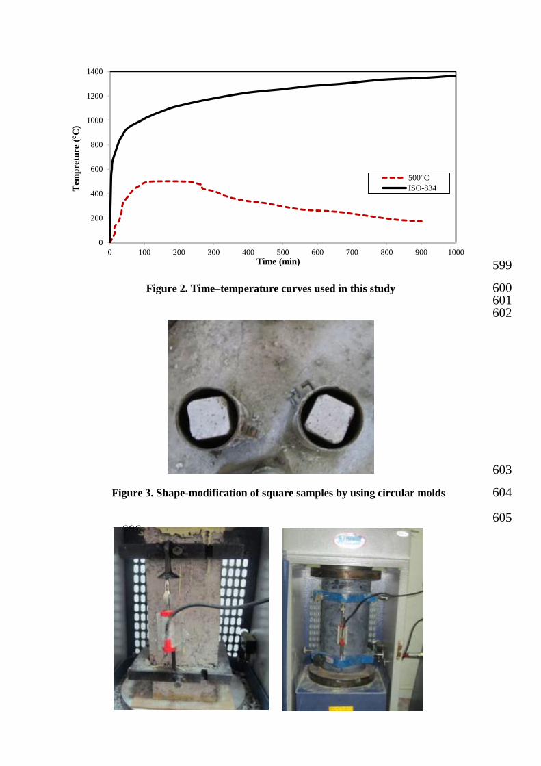
To modify the shape of specimens in the annular gap between cylindrical frameworks 176
(150×300 mm) and prismatic specimens, expansive concrete has been used. Before placing 177
concrete in the corners of the cross-section, a 10 mm chamfer is created to make the 178
aggregates move in the concrete easily (Figure 3). It is noteworthy that before implementing 179
the expansive concrete, the surfaces of the specimen were prepared based on BSEN1504 180
standard [46]. The loose concrete is removed using a steel wire brush and the concrete 181
substrate was prepared to make a better connection between regular concrete and expansive 182
concrete. 183
In addition, the specimens were placed in water before using the expansive concrete since 184
this would prevent regular concrete to absorb the water of the expansive concrete. 185
186
187
188
The specimens were kept in steel formworks for four weeks after using the expansive 189
concrete. Moreover, the top surface of concrete has been regularly moistened using wet 190
clothes. This method of curing causes an increase in the volume of the expansive concrete. 191
However, the formwork did not allow the volume of the concrete to increase. Therefore, this 192
could create compressive stress between regular and expansive concrete leading to a better 193
connection between both types of concrete. 194
Wet lay-up technique has been used for wrapping up the specimens. Before the use of CFRP, 195
the surface of specimens were prepared based on BSEN1504 standard. The epoxy resin called 196
Sikador330 has been used before the CFRP wrapping around the concrete. 197
A thin layer of epoxy was applied on the surfaces of the specimen to fill all the voids, cavities 198
and micro cracks. Then, an initial layer of CFRP was used along fibers for wrapping. The 199
trapped air bubble was removed using roller and hand pressure. This was constantly repeated 200
until full impregnation of composite fibers with adhesive was reached. 201
It should be noted that the mentioned procedure has been replicated for the second layer of 202
CFRP. To have a better connection, 100 mm fiber along the longitudinal direction has been 203
used for overlapping and then a thin layer of epoxy has been applied on the fibers to fully 204
saturate them. The time needed for curing of epoxy is 72 hours in the laboratory environment. 205
206
2.4 Test setup and testing procedure 207
Before testing, all specimens were capped to achieve parallel surfaces and hence uniform 208
load distribution. In order to measure strain, Linear Variable Displacement Transducers 209
(LVDTs) were used. As can be seen from Figure 4, two LVDTs were installed during loading 210
time. The specimens have been tested under axial pressure up to failure by a machine that has 211
a capacity of 2000 KN and the data was monitored and logged by data logger. The strain 212
measurement method for square and circular specimens are presented in Figure 4. 213
214
215
216
217
218
219
220
221
3. Experimental results and discussion 222
3.1 Test observation and failure mode 223
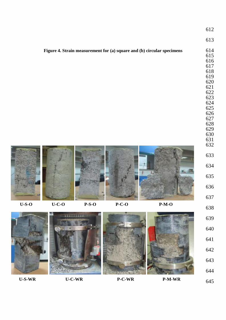
All of the concrete specimens were subjected to uniaxial compression load until failure. 224
Images of specimens after uniaxial compression test can be seen in Figure 5. The U-S-O 225
specimens and the square specimens without strengthening and heating had concrete crushing 226
type of specimen failure. Failure of P-S-O specimens were similar to those of U-S-O 227
specimens except that more cracks or collapse was observed in the P-S-O specimens. On the 228
other hand, for U-S-WR and P-S-WR specimens, failure was owed to concrete crushing 229
which was followed by fracture of CFRP composite jackets at the corners. Brittle fracture is 230
due to stress concentration near the section corners and the lack of confinement at the flat 231
sides, which eliminated membrane action. Failure of U-C-O specimens was due to the 232
combination of column and shear failure whereas the P-C-O specimens had wedge failure. 233
The failures of U-C-WR and P-C-WR specimens were sudden and explosive with loud noise. 234
It was caused by rupture in the CFRP composites. The strengthened circular specimens’ 235
failure was observed at the middle of its height. The rupture mode in the CFRP layers of 236
these specimens represents the accumulation of a large amount of strain energy created as a 237
result of confinement. When failure of shape-modified specimens without CFRP wrapping 238
(P-M-O) is considered, the layer of expansive concrete separated from the main concrete due 239
to low bond. Hence, after the failure, the main concrete was without fracture. For shape- 240
modified specimens with CFRP wrapping like C-WR specimens, the failure has been sudden 241
and explosive with loud booming noise and was due to rupture at the mid-height of the 242
specimen. However, separation between the central core and the expansive concrete has also 243
been observed in these specimens. 244
245
246
247
248
249
250
251
252
253
254
255
256
257
258
259
3.2 The stress-strain behavior of specimens subjected to compression 260
Axial strain has been measured by using two LVDTs. The axial stress was calculated by 261
using the axial compressive load divided by the specimen’s cross-sectional area. Figure 6 262
indicates the axial stress versus axial strain response of all specimens with square cross- 263
section including the reference specimens of (U-S-O), reference specimens with wrapping 264
(U-S-WR), and the specimens with square cross-section exposed to heating, P-S-O and U-S- 265
WR. By comparing the stress-strain diagrams related to the un-heated specimens, it is 266
observed that the CFRP wrapping has no significant influence on the initial slope. However, 267
it has a prominent effect on the strength and ultimate strain of the specimens which can be 268
due to the confinement of the CFRP composite sheets to prevent failures of specimens and to 269
withstand a high strain. On the other hand the specimens exposed to heating have a 270
significant loss of stiffness and strength while, the maximum strain of these specimens has 271
been increased. The reduction in stiffness could be due to small cracks and the pores created 272
in concrete owing to the water evaporation during heating. As can be seen from Figure 6, 273
once the specimens that are strengthened with CFRP composite sheets were subjected to 274
heating, the stiffness and strength of the specimens were increased. However, this growth is 275
not enough for the specimens to reach the stiffness of the baseline specimens. In addition, the 276
increase in strength was almost 56% more than the reference specimens and 20% less than U- 277
S-WR specimens. This reduction is due to the presence of cracks that lead to the loss of 278
strength in the core of heated concrete. 279
280 281
282
Figure 7 presents axial stress versus axial strain of the specimens with circular cross-section 283
including U-C-O, P-C-O, U-C-WR and P-C-WR specimens for comparison with reference 284
specimens (U-S-O). By studying the diagrams related to specimens exposed to heating, it can 285
be concluded that, as expected, the stiffness and the strength were significantly dropped 286
according to expectation. But, after strengthening with CFRP composite wrapping the 287
stiffness was enhanced. However, it should be noted that the increased stiffness is not as high 288
as the initial stiffness. The strength of the specimens was considerably improved after 289
strengthening with CFRP which is due to the confinement effect that prevented the 290
destruction of the central core. 291
292
293
Figure 8 shows the axial stress-strain curve of P-M-O, P-M-WR, U-S-O, U-C-O, P-S-O and 294
P-C-O specimens. The curves of U-S-O, U-C-O, P-S-O and P-C-O were included for 295
comparison purposes. It is obvious from the Figures 6 to 8 that the stiffness of specimens 296
increased with the application of shape modification. Moreover, the strength of shape- 297
modified and wrapped specimens has considerably improved whilst the strength of 298
unwrapped specimens were close to the strength of original specimens. 299
It is noteworthy that shape modification for the damaged specimens could largely 300
compensate the stiffness reduction and the use of CFRP wrapping could considerably 301
improve the compressive strength. However, this was not enough to compensate the stiffness 302
and the strength to return to their initial values. 303
304
3.3 Compressive Strength 305
The results of compressive strength for the studied specimens are given in Figure 9. 306
Compressive strength of the reference specimens was 33.4MPa. When the specimens were 307
heated, the square and the circular specimens had 56% and 42% drop in their compressive 308
strength, respectively. This reduction in strength is attributed to the dehydration of CSH gel 309
as well as to the volumetric expansion resulting from the transformation of the chemical 310
compounds ( ) to CaO. Strengthening by CFRP wrapping of the un-heated specimens 311
caused 98.7% and 122% increase in the compressive strength of the square and the circular 312
specimens, respectively. However, the increase in compressive strength was more remarkable 313
for circular specimens. In addition, strengthening by CFRP composite for specimens 314
subjected to heating led to a prominent increase in their compressive strength which was 315
more than three times higher than those of the P-O specimens. By studying the compressive 316
strength of the square specimens and circular specimens, it is observed that the drop in 317
strength resulted from heating is less for C specimens and also the growth of strength in these 318
series of specimens caused by strengthening with CFRP is more than square specimens. 319
According to the compressive strength of shape-modified specimens, it can be concluded that 320
shape modification and repairing of fire-damaged specimens led to an increase in the 321
compressive strength. This growth was to the extent that for the specimens without wrapping, 322
the compressive strength of shape-modified specimens was reached to the compressive 323
strength of unheated specimens. Once the shape-modified specimens were wrapped by CFRP 324
sheets, their compressive strength showed an increase more than which was two times P-M-O 325
specimens and four times more than P-S-O specimens. This amount is more than U-S-WR 326
and P-S-WR specimens, while it is less than the compressive strength of U-C-WR specimens. 327
This increase in strength is due to both the strength created by expansive concrete and the 328
shape modification of cross sections to circle section. Therefore exerting uniform stress to 329
CFRP sheets and enhancing the confinement effect. 330
331
3.4 Elastic Modulus 332
Figure 10 is presented to provide further examination on the effect of cross-section shape 333
modification and also the effect of strengthening with CFRP on the elastic range of loading of 334
the concrete. 335
336
337
The primary parts of stress-strain curves are linear (Figure 10). The origin point has been 338
linearly connected to a point of stress-strain curve which is corresponding to 40% of 339
maximum stress in reference specimen (U-S-O). It can clearly be concluded (Figure 10) that 340
the influence of shape modification and strengthening with CFRP is obvious on the primary 341
slope and stiffness of stress-strain curve for the studied specimens. The slope of curves for U- 342
S-O, U-S-WR, U-C-O, and U-C-WR specimens is almost identical so that the mentioned 343
curves have been overlapped (Figure 10). 344
The compliance of the four mentioned lines shows that the confinement with CFRP has little 345
impact on the stiffness and primary slope (elastic range) of stress-strain curve. In other words, 346
the effect of strengthening with CFRP in elastic state of loading is negligible. It is observed 347
that the slope of curves has significantly dropped after exposure to heating. This issue is 348
clearly visible in P-S-O and P-C-O specimens but the drop in P-S-O specimen is more that P- 349
C-O specimen. 350
The slope and primary stiffness of specimens has greatly increased owing to the shape 351
modification of cross-sections. However, this growth has not been enough to reach to the 352
initial slope before heating. It is observed that the shape modification can considerably 353
enhance the slope and primary stiffness of stress-strain curve or the stiffness of concrete in 354
elastic state. 355
Figure 11 indicates the effects of heating, shape modification and strengthening with CFRP 356
wrapping on elastic modulus of concrete specimens. In this study, in order to examine the 357
effect of fire on the elastic modulus of concrete in elastic range and also to investigate the 358
proposed strengthening method on restoring the reduction in stiffness, elastic modulus has 359
been used. 360
Elastic modulus is defined as linear slope corresponding to 40% of maximum stress in 361
original specimens (U-S-O) and for P-S-O and P-C-O specimens, it is calculated linear slope 362
according to 40% of maximum stress of these specimens. 363
364
365
366
The average amount of elastic modulus related to the three studied specimens has been 367
presented in Figure 11. This Figure shows that the modulus of elasticity has sharply fallen 368
due to heating effect. This reduction is due to the creation of micro-cracks and softening of 369
the concrete after heating and reduction in bonds. Moreover, increase in porosity due to 370
evaporation of the concrete water is another factor for the reduction. The modulus of 371
elasticity can be improved by strengthening with two layers of CFRP. 372
The modulus of elasticity for U-S-O specimen is 37.1 GPa that has dropped to 2.1 GPa in P- 373
S-O specimen due to heating. Thanks to shape modification, the modulus of elasticity for P- 374
S-O specimens has increased by more than eight times and reached to 17.1 GPa showing the 375
effect of shape modification on elastic modulus or the stiffness of elastic range for heated 376
concrete. However, the effect of confinement on modulus of elasticity of concrete is not 377
perceptible. 378
It is obvious from the Figure 11, the numerical value of elastic modulus for unheated 379
specimens U-S-O, U-S-WR, U-C-O, and U-C-WR is ranges from 34 to 41 GPa. Once the 380
specimens were exposed to 500 °C temperature, elastic modulus sharply drops and reaches to 381
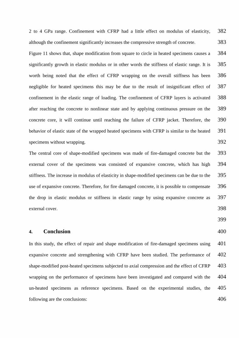
2 to 4 GPa range. Confinement with CFRP had a little effect on modulus of elasticity, 382
although the confinement significantly increases the compressive strength of concrete. 383
Figure 11 shows that, shape modification from square to circle in heated specimens causes a 384
significantly growth in elastic modulus or in other words the stiffness of elastic range. It is 385
worth being noted that the effect of CFRP wrapping on the overall stiffness has been 386
negligible for heated specimens this may be due to the result of insignificant effect of 387
confinement in the elastic range of loading. The confinement of CFRP layers is activated 388
after reaching the concrete to nonlinear state and by applying continuous pressure on the 389
concrete core, it will continue until reaching the failure of CFRP jacket. Therefore, the 390
behavior of elastic state of the wrapped heated specimens with CFRP is similar to the heated 391
specimens without wrapping. 392
The central core of shape-modified specimens was made of fire-damaged concrete but the 393
external cover of the specimens was consisted of expansive concrete, which has high 394
stiffness. The increase in modulus of elasticity in shape-modified specimens can be due to the 395
use of expansive concrete. Therefore, for fire damaged concrete, it is possible to compensate 396
the drop in elastic modulus or stiffness in elastic range by using expansive concrete as 397
external cover. 398
399
4. Conclusion 400
In this study, the effect of repair and shape modification of fire-damaged specimens using 401
expansive concrete and strengthening with CFRP have been studied. The performance of 402
shape-modified post-heated specimens subjected to axial compression and the effect of CFRP 403
wrapping on the performance of specimens have been investigated and compared with the 404
un-heated specimens as reference specimens. Based on the experimental studies, the 405
following are the conclusions: 406
1- Failure of specimens without wrapping was due to concrete crushing. While, in the 407
wrapped specimens, the failure was owing to concrete crushing, followed by rupture 408
of CFRP composite with explosion and a loud booming noise. Failure in shape- 409
modified specimens without wrapping has been in the form of separation of the two 410
concrete layers from each other. Whereas, failure in shape modified specimens with 411
wrapping was similar to the wrapped circular specimens. 412
2- The compressive strength of the concrete specimens, which are exposed to 500 °C 413
heat, has significantly decreased. This reduction for S series specimens and C series 414
specimens has respectively been 56% and 42% relative to un-heated specimens. 415
3- The compressive strength of the specimens after strengthening with two layers of 416
CFRP wrapping has significantly increased. This increase in the un-heated specimens 417
was more than twice and for fire-damaged specimens was significant and reached to 418
more than three times of the growth for the P-O specimens. 419
4- Shape modification and repairing of the fire-damaged specimens caused increase in 420
compressive strength and in unwrapped specimens has reached to the strength of 421
square specimens. When they are strengthened, the strength has enhanced more than 422
two times that of unwrapped specimens and more than four times than heated square 423
specimens. 424
5- The initial slope of the curve related to the unheated specimens and also the unheated 425
confined specimens has nearly been identical and consistent with each other. 426
However, by placing the specimens exposed to the heat, the slope in elastic state of 427
specimens has been sharply decreased and confinement also has little effect on the 428
initial stiffness. Therefore, the slope of stress-strain curve in elastic range could be 429
considerably increased and has been largely compensated for fire-damaged specimens 430
using shape modification. 431
6- The modulus of elasticity has been sharply decreased due to heating. The reduction in 432
modulus of elasticity of fire-damaged specimens has been more than the reduction in 433
compressive strength of specimens. 434
7- The effect of CFRP wrappings on the modulus of elasticity has been negligible being 435
as a result of weak effect of concrete confinement in elastic state of loading. Although 436
shape modification of a square section to a circle section has a considerable effect on 437
the modulus of elasticity of fire-damaged specimens so that with shape modification, 438
the reduction in this parameter was compensated to a large and increased more than 8 439
times with respect to the damaged specimens, while not reaching to the initial value. 440
441
References 442
[1] Yaqub, M. Bailey, C.G. “Repair of fire damaged circular reinforced concrete columns 443
with CFRP composites”, Construction and Building Materials, 25, pp. 359–370, (2011). 444
[2] Concrete Society Assessment, “design and repair of fire-damaged concrete structures”, 445
Technical report, no. 68, Camberley, Surrey, UK, (2008). 446
[3] Bastami, M. Chaboki-Khiabani, A. Baghbadrani, M. Kordi, M. “Performance of high 447
strength concretes at elevated temperatures”, Scientia Iranica, 18(5), pp.1028–1036 448
(2011). 449
[4] Mehta, P.K. and Monteiro, P.J.M, “Concrete: Microstructure, Properties, and Materials”, 450
McGraw-Hill, New York, NY, USA, (2006). 451
[5] Chen, G.M. He, Y.H. Yang, H. Chen, J.F. Guo, Y.C., “Compressive behavior of steel 452
fiber reinforced recycled aggregate concrete after exposure to elevated temperatures”, 453
Construction and Building Materials, 71, pp.1–15, (2014). 454
[6] Gupta, T. Siddique, S. Sharma, R. K. Chaudhary, S., “Effect of elevated temperature and 455
cooling regimes on mechanical and durability properties of concrete containing waste 456
rubber fiber”, Construction and Building Materials ,137, pp.35–45, (2017). 457
[7] Huang, Z. Liew, J.Y.R. Li, W., “Evaluation of compressive behavior of ultra-lightweight 458
cement composite after elevated temperature exposure”, Construction and Building 459
Materials, 148, pp.579–589, (2017). 460
[8] Baradaran-Nasiri, A. and Nematzadeh, M., “The effect of elevated temperatures on the 461
mechanical properties of concrete with fine recycled refractory brick aggregate and 462
aluminate cement”, Construction and Building Materials, 147, pp.865–875, (2017). 463
[9] Xiong, M.X, Liew, J.Y.R., “Mechanical behaviour of ultra-high strength concrete at 464
elevated temperatures and fire resistance of ultra-high strength concrete filled steel 465
tubes”, Materials and Design, 104, pp.414–427, (2016). 466
[10] Li, L. Jia, P. Dong, J. Shi, L. Zhang, G. Wang, Q., “Effects of cement dosage and 467
cooling regimes on the compressive strength of concrete after post-fire-curing from 468
800°C”, Construction and Building Materials, 142, pp.208–220,(2017). 469
[11] Xiao, J. Li, Zh. Xie, Q. Shen, L., “Effect of strain rate on compressive behaviour of 470
high-strength concrete after exposure to elevated temperatures”, Fire Safety Journal, 83, 471
pp.25–37,(2016). 472
[12] Choi, E. Kim, Y.W. Chung, Y.S. Yang, K.T., “Bond strength of concrete confined by 473
SMA wire jackets”, Phys Proc, 10, pp.210–215, (2010). 474
[13] Choi, E. Chung, Y.S. Kim, Y.W. Kim, J.W., “Monotonic and cyclic bond behavior of 475
confined concrete using NiTiNb SMA Wires”, Smart Mater Struct, 20(7), pp.1–11, 476
(2011). 477
[14] Calderón, P.A. Adam, J.M. Ivorra, S. Pallarés, S.F. Giménez, E. “Design strength of 478
axially loaded RC columns strengthened by steel caging”, Materials & Design, 30(10), 479
pp. 4069–4080, (2009). 480
[15] Turgay, T. Polat, Z. Koksal, H.O. Doran, B. Karakoç, C. “Compressive behavior of 481
large-scale square reinforced concrete columns confined with carbon fiber reinforced 482
polymer jackets”, Materials & Design, 31(1), pp. 357–364, (2010). 483
[16] Bisby, L.A. Green, M.F. Kodur, V.K.R. “Fire endurance of fiber-reinforced 484
polymerconfined concrete columns”, ACI Struct J, 102(6), pp. 883–891, (2005). 485
[17] Chowdhury, E.U. Bisby, L.A. Green, M.F. Kodur, V.K.R. “Investigation of insulated 486
CFRP wrapped reinforced concrete columns in fire”, Fire Safety J, 42(6), pp. 452–460, 487
(2007). 488
[18] Maghsoudi, A.A and Akbarzadeh Bengar, H. “Acceptable lower bound of the ductility 489
index and serviceability state of RC continuous beams strengthened with CFRP sheets”, 490
Scientia Iranica, 18(1), pp. 36-44, (2011). 491
[19] Ghasemi, S. Maghsoudi, A.A. Akbarzadeh Bengar, H. Ronagh, H.R. “Sagging and 492
Hogging Strengthening of Continuous Unbonded Posttensioned HSC Beams by NSM and 493
EBR”, J. Compos. Constr, 20(2), (2016). 494
[20] Balaguru, P. Nanni, A. Giancaspro, J. “CFRP composites for reinforced and prestressed 495
concrete structures”, Taylor and Francis, New York, (2009). 496
[21] Yan, Z. “Shape modification of rectangular columns confined with CFRP composites”, 497
Phd thesis, Salt Lake City (UT), Dept. Civil and Environmental Eng., University of Utah, 498
(2005). 499
[22] Behzard, P. Sharbatdar, M.K. Kheyroddin, A. “Different NSM CFRP technique for 500
strengthening of RC two-way slabs with low clear cover thickness”, Scientia Iranica, 501
23(2), pp. 520-534 (2016). 502
[23] Shin, J. Scott, D.W. Stewart, L.K. Yang, Ch. Wright, T.R. Roches, R.D. “Dynamic 503
response of a full-scale reinforced concrete building frame retrofitted with CFRP column 504
jackets”, Engineering Structures, 125, pp. 244–253, (2016). 505
[24] Hadi, M.N.S. “Behaviour of eccentric loading of CFRP confined fibre steel reinforced 506
concrete columns”, Constr Build Mater, 23(2), pp. 1102–1108, (2009). 507
[25] Parvin, A. Altay, S. Yalcin, C. Kaya, O. “CFRP rehabilitation of concrete frame joints 508
with inadequate shear and anchorage details”, J Compos Constr, 14(1), (2010). 509
[26] Teng, J.G. Chen, J.F. Smith, S.T. Lam, L. “CFRP strengthened RC structures”, Wiley 510
Chichester, (2002). 511
[27] Debaiky, S.A. Green, M.F. Hope, B.B. “Carbon fibre-reinforced polymer wraps for 512
corrosion control and rehabilitation of reinforced concrete columns.”, ACI Mater J, 99(2), 513
pp. 129–137 (2002). 514
[28] Ilia, E. Mostofinejad, D. Moghaddas, A. “Performance of corner strips in CFRP 515
confinement of rectilinear RC columns”, Scientia Iranica, 22(6), pp. 2024–2032, (2015). 516
[29] Issa, M.A. Rajai, Z.A. “Experimental and parametric study of circular short columns 517
confined with CFRP composites”, J Compos Constr, 13(2), pp. 135–147, (2009). 518
[30] Maaddawy, T. “Post-repair performance of eccentrically loaded RC columns wrapped 519
with CFRP composites”, Cement Concr Compos, 30(9), pp. 822–830, (2008). 520
[31] Toutanji, H. Han, M. Gilbert, J. Matthys, S. “Behaviour of large scale rectangular 521
columns confined with CFRP composites”, J Compos Constr (ASCE), 29, (2009). 522
[32] Chowdhury, E.U. Bisby, L.A. Green, M.F. Kodur, V.K.R. “Residual behaviour of fire 523
exposed reinforced concrete beams prestrengthened in flexure with fibre reinforced 524
polymer sheets.”, J Compos Constr, 12(1), pp. 44–52, (2008). 525
[33] Haddad, R.H. Shannag, M.J. Hamad, R.J. “Repair of heat damaged reinforced concrete 526
T-beams using FRC jackets”, J Mag Concr Res, 59(3), pp. 223–231, (2007). 527
[34] Yan, Z. Zhisheng, X.U. “Experimental study on safety test for reinforced concrete 528
columns strengthened with carbon fibre reinforced polymers after fire.”, Disaster 529
Prevention Science and Safety Technology Institute, Central South University, Changsha, 530
China, (2005). 531
[35] Zhong, T. Lin-Hai, H. “Behaviour of fire-exposed concrete-filled steel tubular beam 532
columns repaired with CFRP wraps”, J Thin-walled Struct, 45(1), pp. 63–76, (2007). 533
[36] Zhong,T. Lin-Hai, H. Ling-Ling, W. “Compressive and flexural behavior of CFRP- 534
repaired concrete-filled steel tubes after exposure to fire.”, J Constr Steel Res, 63(8), 535
pp.1116–1126, (2007). 536
[37] Karbhari, V.M, Gao, Y. “Composite jacketed concrete under uniaxial compression 537
verification of simple design equations.” J Mater Civil Eng ASCE, 9(4), pp. 185–193, 538
(1997). 539
[38] Rochette, P. Labossière, P. “Axial testing of rectangular column models confined with 540
composites”, J Compos Constr ASCE, 4(3), pp. 129–136, (2000). 541
[39] Maaddawy, T.E. Sayed, M.E Abdel-Magid, B. “The effects of cross-sectional shape and 542
loading condition on performance of reinforced concrete members confined with Carbon 543
Fiber-Reinforced Polymers”, Materials & Design, 31, pp. 2330–2341, (2010). 544
[40] Yan, Z. Pantelides, C.P. “Concrete column shape modification with FRP shells and 545
expansive cement concrete”, Construction and Building Materials, 25, pp. 396–405, 546
(2011). 547
[41] Ma, Ch. Apandi, N. Yung, S. Hau, Ng. Haur, L. Awang, A. Omar, W., “Repair and 548
rehabilitation of concrete structures using confinement: A review”, Construction and 549
Building Materials, 133, pp. 502–515, (2017). 550
[42] Shin, J. Scott, D.W. Stewart, L.K. Yang, C.S. DesRoches, R. “Dynamic response of a 551
full-scale reinforced concrete building frame retrofitted with FRP column jackets”, 552
Engineering Structures, 125, pp. 244–253, (2016). 553
[43] Molhotra, H.L. “The effect of temperature on the compressive strength of concrete”, 554
Mag. Concr. Res, 8(22), pp. 85–94, (1956). 555
[44] Wu, B. Ma, Z.C. Ou, J.P. “Experimental research on deformation and constitutive 556
relationship of concrete under axial loading and high temperature”, J. Build. Struct, 20(5), 557
pp. 42–49, (1999). 558
[45] Chang, Y.F. Chen, Y.H. Sheu, M.S. Yao,G.C. “Residual stress strain relationship for 559
concrete after exposure to high temperatures”, Cement and Concrete Research, 36, pp. 560
1999–2005, (2006). 561
[46] The Concrete Society, “Repair of concrete structures with reference to BS EN 1504”, 562
Technical report no.69, (2009). 563
List of table captions: 564 565 Table 1. Details of tested specimens 566
Table 2. Carbon fiber reinforced polymer characteristics 567
568
List of figure captions: 569 570 Figure 1. Furnace with concrete cylinders ready for heating 571
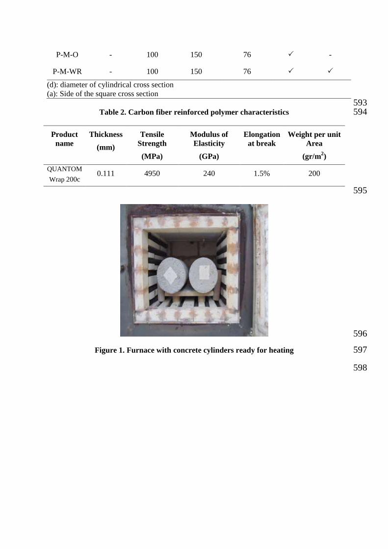
Figure 2. Time–temperature curves used in this study 572
Figure 3. Shape-modification of square samples by using circular molds 573
Figure 4. Strain measurement for (a) square and (b) circular specimens 574
Figure 5. Failed square and circular, unheated and post heated specimens with and without 575
shape modification 576
Figure 6. Axial stress- strain behavior of specimens with square cross-section 577
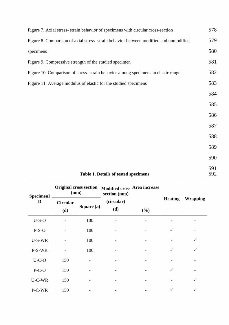
Figure 7. Axial stress- strain behavior of specimens with circular cross-section 578
Figure 8. Comparison of axial stress- strain behavior between modified and unmodified 579
specimens 580
Figure 9. Compressive strength of the studied specimen 581
Figure 10. Comparison of stress- strain behavior among specimens in elastic range 582
Figure 11. Average modulus of elastic for the studied specimens 583
584
585
586
587
588
589
590
591 Table 1. Details of tested specimens 592
SpecimenI
D
Original cross section
(mm) Modified cross
section (mm)
(circular)
(d)
Area increase
(%)
Heating Wrapping Circular
(d) Square (a)
U-S-O - 100 - - - -
P-S-O - 100 - - -
U-S-WR - 100 - - -
P-S-WR - 100 - -
U-C-O 150 - - - - -
P-C-O 150 - - - -
U-C-WR 150 - - - -
P-C-WR 150 - - -
P-M-O - 100 150 76 -
P-M-WR - 100 150 76
(d): diameter of cylindrical cross section
(a): Side of the square cross section
593 Table 2. Carbon fiber reinforced polymer characteristics 594
Weight per unit
Area
(gr/m2)
Elongation
at break
Modulus of
Elasticity
(GPa)
Tensile
Strength
(MPa)
Thickness
(mm)
Product
name
200 1.5% 240 4950 0.111 QUANTOM
Wrap 200c
595
596
Figure 1. Furnace with concrete cylinders ready for heating 597
598
599
Figure 2. Time–temperature curves used in this study 600 601 602
603
Figure 3. Shape-modification of square samples by using circular molds 604
605 606
607
608
609
610
611
0
200
400
600
800
1000
1200
1400
0 100 200 300 400 500 600 700 800 900 1000
Tem
pre
ture
(°C
)
Time (min)
500°C
ISO-834
612
613
Figure 4. Strain measurement for (a) square and (b) circular specimens 614 615 616 617 618 619 620 621 622 623 624 625 626 627 628 629 630 631
632
633
634
635
636
637
638
639
640
641
642
643
644
645
U-S-O U-C-O P-S-O P-C-O P-M-O
U-S-WR U-C-WR P-C-WR P-M-WR
b a
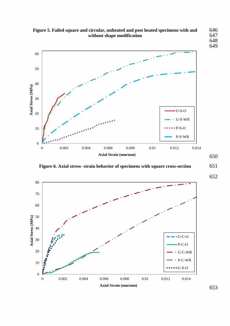
Figure 5. Failed square and circular, unheated and post heated specimens with and 646 without shape modification 647
648 649
650
Figure 6. Axial stress- strain behavior of specimens with square cross-section 651
652
653
0
10
20
30
40
50
60
0 0.002 0.004 0.006 0.008 0.01 0.012 0.014
Axia
l S
tres
s (M
Pa
)
Axial Strain (mm/mm)
U-S-O
U-S-WR
P-S-O
P-S-WR
0
10
20
30
40
50
60
70
80
0 0.002 0.004 0.006 0.008 0.01 0.012 0.014
Axia
l S
tres
s (M
Pa
)
Axial Strain (mm/mm)
U-C-O
P-C-O
U-C-WR
P-C-WR
U-S-O
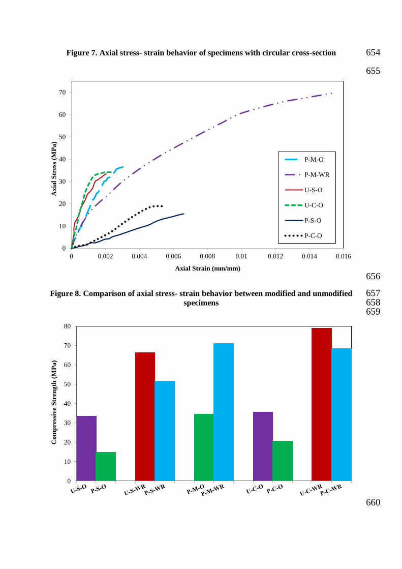
Figure 7. Axial stress- strain behavior of specimens with circular cross-section 654
655
656
Figure 8. Comparison of axial stress- strain behavior between modified and unmodified 657 specimens 658
659
660
0
10
20
30
40
50
60
70
0 0.002 0.004 0.006 0.008 0.01 0.012 0.014 0.016
Axia
l S
tres
s (M
Pa
)
Axial Strain (mm/mm)
P-M-O
P-M-WR
U-S-O
U-C-O
P-S-O
P-C-O
0
10
20
30
40
50
60
70
80
Co
mp
ress
ive
Str
eng
th (
MP
a)
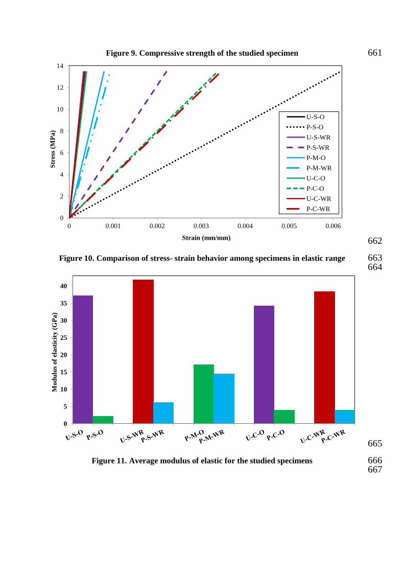
Figure 9. Compressive strength of the studied specimen 661
662
Figure 10. Comparison of stress- strain behavior among specimens in elastic range 663 664
665
Figure 11. Average modulus of elastic for the studied specimens 666 667
0
2
4
6
8
10
12
14
0 0.001 0.002 0.003 0.004 0.005 0.006
Str
ess
(MP
a)
Strain (mm/mm)
U-S-O
P-S-O
U-S-WR
P-S-WR
P-M-O
P-M-WR
U-C-O
P-C-O
U-C-WR
P-C-WR
0
5
10
15
20
25
30
35
40
Mo
du
lus
of
ela
stic
ity
(G
Pa
)