Embed Size (px)
Citation preview
1047
SP-230—59
Shape Modification with ExpansiveCement Concrete for Confinement with
FRP Composites
by Z. Yan, C.P. Pantelides, and L.D. Reaveley
SSSSSyyyyynopnopnopnopnopsssssiiiiis:s:s:s:s: To improve the confinement effectiveness of FRP composites for square andrectangular columns, shape modification is performed by using prefabricated FRP shellscombined with expansive cement concrete. Chemical post-tensioning using expansivecement concrete is used to change the FRP confinement from “passive” to “active”.Experimental results are presented demonstrating the effectiveness of this method. Ananalytical stress-strain model is developed for shape-modified FRP-confined columnswith expansive cement concrete which is based on the modified Willam-Warnkeplasticity model, the Popovics general stress-strain concrete model, and the dilatancybehavior obtained from the present study. This model is implemented by anincremental approach which accounts for the variable FRP confinement during theloading process. The analytical results show satisfactory agreement with theexperiments.
Keywords: chemical post-tensioning; confinement; expansive cementconcrete; FRP composites; stress-strain behavior
1048 Yan et al.Zihan Yan is a structural engineer for Nishkian Meninger, San Francisco, CA. He
received his PhD from University of Utah, Salt Lake City, Utah. His research interests
include strengthening of concrete with fiber-reinforced polymer composites, and
structural diagnostics and rehabilitation of reinforced concrete building and construction.
ACI member Chris P. Pantelides is a professor of civil and environmental engineering at
the University of Utah. He is a member of ACI Committee 374, Performance-Based
Seismic Design of Concrete Buildings. His research interests include seismic design,
evaluation, and rehabilitation of reinforced concrete building and bridge construction.
ACI member Lawrence D. Reaveley is a professor of civil and environmental
engineering at the University of Utah. He is a member of ACI Committee 369. Seismic
Repair and Rehabilitation. His research interests include the areas of performance-based
structural engineering and the rehabilitation of existing structures.
INTRODUCTION
Fiber Reinforced Polymer (FRP) composites have been used in the retrofit of
concrete columns to improve their capacity, displacement ductility or both. It is well-
known that FRP composite jackets can provide effective lateral confinement for circular
concrete columns, and substantially enhance their axial strength and ultimate axial strain;
however, FRP confinement is much less effective for square and rectangular columns
compared to circular columns. This observation has been verified in tests performed by
Rochette and Labossière (2000) and Pessiki et al. (2001). The reason for this is that FRP
composite jackets resist axial loads by membrane action, and are more effective for
circular sections as opposed to square or rectangular column sections with corners and
long flat sides; stress concentrations at the corners and inefficient confinement at the flat
sides cause loss of membrane action of the FRP composite and reduction of confinement.
Because of the presence of steel ties, rounding of the corner radius in existing
square/rectangular columns is limited. In addition, lower FRP confinement effectiveness
results in softening behavior for square and rectangular columns and the FRP composite
ruptures prematurely; therefore, the high strength of FRP composite materials cannot be
fully utilized.
A possible approach to increasing the effectiveness of FRP-confined rectangular
columns is to perform shape-modification that is to modify the column cross-section into
an elliptical, oval, or circular section. One method for performing shape-modification is
to use prefabricated (non-bonded) FRP composite shells combined with expansive
cement concrete. For this method, a prefabricated elliptical/oval/circular FRP shell may
be used as stay-in-place formwork for casting additional expansive cement concrete
around the square or rectangular section to achieve shape modification. The advantage of
using expansive cement concrete is that a post-tensioning effect could be achieved on the
FRP composite shell through chemical post-tensioning, which would in turn improve the
compressive behavior of concrete columns. Expansive cement consists of a Portland
FRPRCS-7 1049cement component and a calcium-sulfoaluminate anhydrite component; the hydration of
the latter component causes expansion. This material has been used since 1960 for
making chemically prestressed concrete. Klein et al. (1961) investigated the properties of
expansive cement for chemical post-tensioning and found that factors influencing the
magnitude and rate of the expansive reaction include: chemical composition of
components, proportions of the two components in the total cementing material, richness
of mix, conditions of curing, and degree of restraint. Benuska et al. (1971) further
studied the curing effects on expansion and mechanical behavior of expansive cement
concrete; their tests showed that expansive cement concrete was very good for
prefabricated elements or structural elements and systems in which the optimum amount
of chemical prestress required was relatively low.
The mechanism of expansive cement concrete is used with FRP composite
shells for confinement enhancement. When expansive cement concrete is applied to
prefabricated FRP shells, expansion of the cement grout is restrained by the FRP shell;
the FRP composite is stressed in tension, thus creating a post-tensioning effect. It is
obvious that this post-tensioning effect would increase the confinement behavior of FRP
jackets and change the confinement action from “passive” to “active”.
In this paper, an experimental program was conducted for studying shape
modification of square/rectangular specimens confined with FRP composites. Two FRP
composite systems, a Carbon Fiber Reinforced Polymer (CFRP) system and a Glass Fiber
Reinforced Polymer (GFRP) system were used. Column shape modification was
performed by using prefabricated FRP composite shells with expansive cement concrete.
Test results are presented regarding failure modes and the stress-strain behavior;
comparison is made between shape-modified specimens and specimens without shape
modification.
This paper also presents an analytical stress-strain model for the shape-modified
concrete column with the FRP composite shell and expansive cement concrete. As a part
of this research, a plasticity model based on the Willam-Warnke (1975) plasticity
concrete model was developed to account for the axial strength of FRP-confined concrete
Conclusions regarding the effectiveness of the shape modification method with expansive
cement concrete and its practical implementation are made.
RESEARCH SIGNIFICANCE
Confinement of concrete utilizing shape modification of square and rectangular
columns with post-tensioned non-bonded FRP composite shells and expansive cement
concrete is investigated. Square and rectangular sections were modified into circular and
elliptical sections; post-tensioning of the FRP composite shells reduces corner effects,
and enhances membrane action and confinement effectiveness. It is shown that
expansive cement concrete is an efficient method for post-tensioning FRP composite
shells and modifying the FRP confinement from passive to active. The proposed
analytical model shows a good agreement with the experimental results.
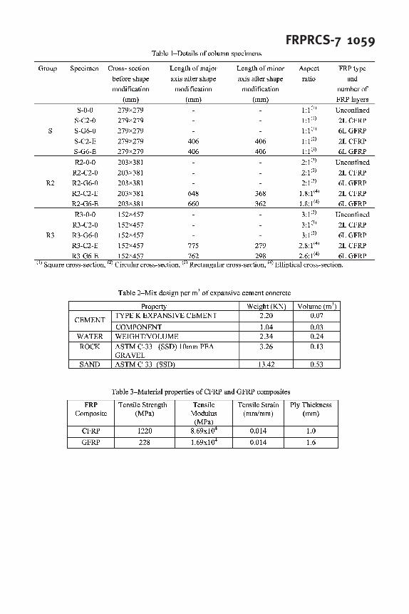
1050 Yan et al.EXPERIMENTAL PROGRAM
Specimens
The experimental program involved three groups of specimens: S, R2 and R3;
“S” denotes a series of square specimens; “R2” and “R3” denote a series of rectangular
specimens with cross-sectional aspect ratio of 2:1 and 3:1, respectively. All specimens
were 914 mm high; no steel reinforcement was used inside the concrete. Each group
included an unconfined (baseline) specimen, two specimens with the original cross-
section confined by CFRP or GFRP composites, and two shape-modified specimens by
using prefabricated CFRP or GFRP shells and expansive cement concrete. Table 1 lists
the details of all specimens; the identification of the specimens, as shown in Table 1, uses
a three-code base. The first part of the code is the shape of the column (Square or
Rectangular), and the aspect ratio of the rectangular cross-section (2:1 or 3:1). The
second part of the code indicates the type of FRP composite (CFRP or GFRP) and the
number of layers (2 or 6). The third part denotes the type of material used to achieve
shape modification (E denotes Expansive cement concrete and 0 denotes no shape
modification, i.e. the specimen has the original square or rectangular geometry). The
modified cross-section of the original square specimen was circular and the modified
cross-section of the original rectangular specimen was elliptical; the cross-sectional
aspect ratio was close to the original prior to shape modification.
Material properties
Two types of concrete were used in this study: regular concrete and expansive
cement concrete. Regular concrete was used to cast the original specimens; expansive
cement concrete was used to perform the shape modification. The concrete compressive
strength for the original specimens was 15 MPa. The expansive cement used in this
research was Type-K and Komponent. The two principal constituents of Komponent are
calcium sulfoaluminate and gypsum or calcium sulfate. The formation of ettringite
crystals, which result from hydration of the two ingredients, is what causes the expansion.
When expansion is restrained, for example by a pre-fabricated FRP composite shell,
expansive cement concrete induces tensile stresses in the FRP composite shell that cause
chemical “post-tensioning”. The mix design for the expansive cement concrete is listed
in Table 2. The compressive strength of the expansive cement concrete after 28 days was
10 MPa.
Two FRP composite materials were used to confine the concrete columns. One
was SikaWrap Hex 103C which is a high strength, unidirectional carbon fiber fabric with
epoxy resin. The other was Aquawrap G-06, which is a unidirectional pre-impregnated
glass fiber fabric with urethane resin. Both FRP composite materials were cured at
ambient temperature conditions. The material properties determined from tensile coupon
tests, per ASTM Standard D3039, are shown in Table 3.
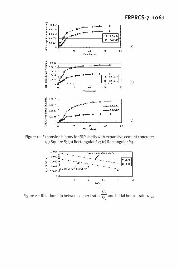
For shape-modified specimens, prefabricated FRP composite shells were made
prior to casting of expansive cement concrete. Strain gauges were installed on the FRP
composite at midheight of the specimens and a data acquisition system was used to
measure the hoop expansion of the FRP composite shells during the curing period of the
expansive cement concrete. Figure 1 shows the measured FRP hoop strain versus time
FRPRCS-7 1051starting at casting of the expansive cement concrete. The FRP hoop strain approached a
constant value after 60 days and this asymptotic value is defined as the initial hoop strain
inij ,ε , which refers to the state before axial load is applied. The initial hoop strain
inij ,ε
depends on the aspect ratio Bj /D
j of the prefabricated FRP shells, which is defined as the
length of the major axis, j
B , to the length of the minor axis, j
D , of the elliptical cross-
section. In general, circular jackets achieved the highest expansion while the elliptical
shell with the highest aspect ratio had the smallest expansion. Also, GFRP shells
achieved a higher expansion compared to CFRP shells. These observations can be
visualized from Fig. 2 for the relationship between inij ,
ε and the aspect ratio. From Fig.
2, the proposed relationship between inij ,
ε and Bj /D
j for FRP shells with 2 CFRP layers
is:
−=
j
j
inij
D
B
00041.00020.0,
ε (1)
and for FRP shells with 6 GFRP layers is:
−=
j
j
inij
D
B
00041.00025.0,
ε (2)
Loading and instrumentation
All specimens were subjected to a monotonic uniaxial load until failure under
displacement control with a constant loading rate of 1.3 mm per minute. The tests were
performed using a 9 MN actuator with a stroke of 0.6 m. Two Linear Variable
Differential Transducers (LVDTs) were installed to measure axial compressive strains;
strain gauges were used to measure the transverse strains over the circumference of the
cross-section.
EXPERIMENTAL RESULTS AND DISCUSSION
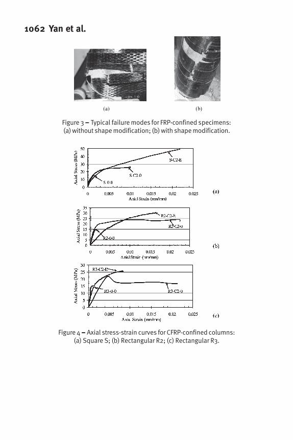
Failure modes
For FRP-confined square/rectangular specimens without shape modification,
failure typically starts with concrete crushing followed by fracture of the FRP composite
jacket. In rectangular and square sections, FRP breakage appeared at one of the corners,
in a small area near the column midheight; a concrete cone was seen after peeling the
broken FRP composite jacket. The failure was brittle due to the presence of the corner
and flat side effects, which eliminate membrane action of the FRP jacket and result in
weaker confinement. Figure 3(a) shows the typical failure mode for the FRP-confined
specimen with the bonded FRP jacket.
In contrast to specimens with bonded FRP jackets, the failure of shape-modified
specimens with non-bonded FRP shells and expansive cement concrete was fracture of
the FRP jackets first, followed by cracking of the expansive cement concrete and
concrete core. FRP breakage extended over the entire height of the column, showing the
extensive participation of the FRP jacket in confinement. At the end of the test, most
1052 Yan et al.specimens remained in one piece, and shear and compression cracks were seen in the
expansive cement concrete. Figure 3(b) shows the typical failure mode for a shape-
modified specimen with non-bonded FRP shells and expansive cement concrete.
Specimens with non-bonded FRP shells and expansive cement concrete had a higher
strain ductility compared to specimens with bonded FRP jackets, demonstrating the
higher effectiveness of the post-tensioned FRP shells. The degree of damage of shape-
modified specimens with non-bonded FRP shells and expansive cement concrete varied
with aspect ratio. Specimens with a smaller aspect ratio reached a higher capacity and a
higher degree of damage.
Axial stress-strain response
Figure 4 presents the axial stress versus axial strain response for each group,
including the baseline specimens and the specimens confined with CFRP composite
jackets. The axial displacements were measured using the average of two LVDTs, and
the axial stress was computed by dividing the axial compression load by the cross-
sectional area. It is seen that CFRP-confined square specimen S-C2-0 showed a limited
hardening behavior and both CFRP-confined rectangular specimens R2-C2-0 and R3-C2-
0 demonstrated a softening behavior; a drop of axial stress was observed after the initial
axial strength was reached, and the degree of softening increased as the aspect ratio
increased. For shape-modified specimens, the stress-strain curves show ascending
branches without softening behavior. In some cases, the initial slope of the stress-strain
curve for shape-modified specimens is less than that of specimens without shape
modification. This is because the unconfined compressive strength of expansive cement
concrete was smaller than that of regular concrete, and the membrane effect from the
FRP composite shell was not significant in the initial phase of axial loading. Similar
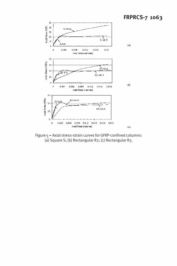
observations were made for GFRP-confined specimens, as shown in Fig. 5. It is also
noted from Fig. 5(c) that very limited increases as well as the limited hardening behavior
were obtained for shape-modified specimen R3-G6-E compared to the specimen confined
with the bonded FRP jacket, R3-G6-0, showing that the GFRP composite is more
sensitive to the cross-sectional aspect ratio.
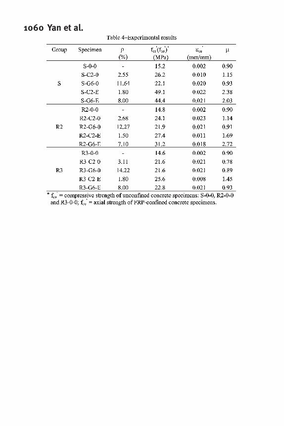
To characterize the stress-strain behavior of FRP-confined concrete columns,
three important parameters are identified: axial strength, ultimate axial strain, and
ductility ratio µ , as shown in Table 4. The ductility ratio is used to evaluate the ductility
performance of FRP-confined concrete and is calculated as the ratio of the total area
under the stress-strain curve to the area bounded by a slope of the initial elastic stiffness
and the plastic plateau (Rochette and Labossière 2000); for specimens with hardening
behavior the plastic plateau passes through the unconfined concrete strength
'
co
f ; for
specimens with softening behavior the plastic plateau passes through the peak axial
strength
'
cc
f . In Table 4, the volumetric ratio of the FRP composite jacket for each
specimen FRP
ρ is also presented; FRP
ρ is the ratio of the area of the FRP composite
jacket to the cross-sectional area of the concrete specimen.
FRPRCS-7 1053It can be seen from Figs. 4, 5 and Table 4 that the shape-modified specimens
showed significant increases in axial strength, ultimate axial strain, and ductility.
However, the level of improvement of the compressive behavior depends on the aspect
ratio. As seen from Figs. 4 and 5, the improvement is significant for shape-modified
square specimens S-C2-E and S-G6-E since their modified shape was circular; the
improvement was less significant for shape-modified rectangular specimens R3-C2-E and
R3-G6-E with the higher aspect ratio; this means that the effect of shape modification is
reduced as the section becomes a flatter ellipse. Therefore, to improve the confinement
effectiveness, a lower aspect ratio after shape modification is preferred, in the form of an
oval shape. However, the practical use of a prefabricated FRP shell with a low aspect
ratio such as an oval shape always increases the modified cross-sectional area by a large
amount of concrete, and possible foundation issues resulting in cost increases.
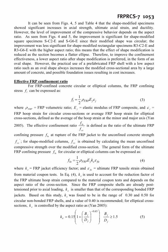
Effective FRP confinement ratio
For FRP-confined concrete circular or elliptical columns, the FRP confining
stress l
f can be expressed as:
jjFRPlEf ερ
2
1
= (3)
where FRP
ρ = FRP volumetric ratio; j
E = elastic modulus of FRP composite, and j
ε =
FRP hoop strain for circular cross-sections or average FRP hoop strain for elliptical
cross-sections, defined as the average of the hoop strain at the minor and major axis (Yan
2005). The effective confinement ratio '
co
lu
f
f
is defined as the ratio of the ultimate FRP
confining pressure lu
f at rupture of the FRP jacket to the unconfined concrete strength
'
co
f ; for shape-modified columns, '
co
f is obtained by calculating the mean unconfined
compressive strength over the modified cross-section. The general form of the ultimate
FRP confining pressure lu
f for circular or elliptical columns can be expressed as:
fujFRPlukEf ερε
2
1
= (4)
where ε
k = FRP jacket efficiency factor; and fu
ε = ultimate FRP tensile strain obtained
from material coupon tests. In Eq. (4), ε
k is used to account for the reduction factor of
the FRP ultimate hoop strain compared to the material coupon tests and depends on the
aspect ratio of the cross-section. Since the FRP composite shells are already post-
tensioned prior to axial loading, ε
k is smaller than that of the corresponding bonded FRP
jackets. Based on this study, ε
k was found to be in the range of 0.30 and 0.50 for
circular non-bonded FRP shells, and a value of 0.40 is recommended; for elliptical cross-
sections, ε
k is controlled by the aspect ratio as (Yan 2005):
5.1115.0
65.0
≥
+=
−
j
j
j
j
D
B
D
B
kε
(5)
1054 Yan et al.
The effective confinement ratio '
co
lu
f
f
is also an indication of the trend of the stress-strain
behavior; the authors suggest that the FRP-confined column shows a strain hardening
behavior when '
co
lu
f
f
is larger than 0.2 and a strain softening behavior when '
co
lu
f
f
is
smaller than 0.2 (Yan 2005).
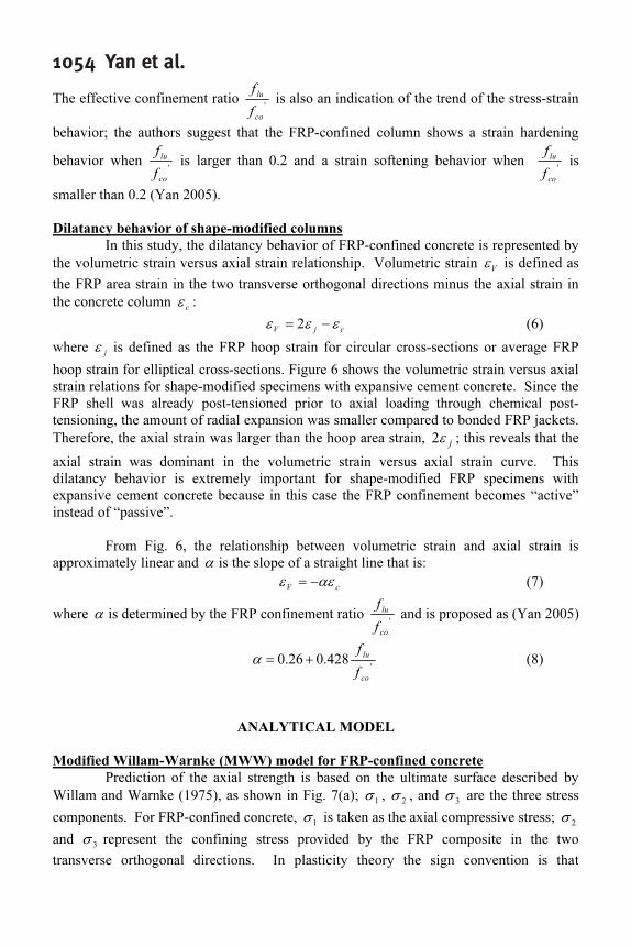
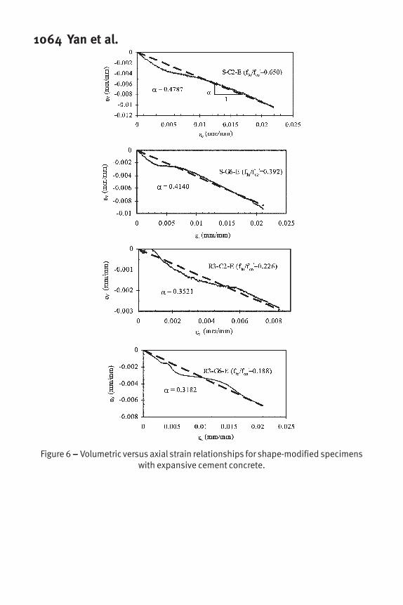
Dilatancy behavior of shape-modified columns
In this study, the dilatancy behavior of FRP-confined concrete is represented by
the volumetric strain versus axial strain relationship. Volumetric strain V
ε is defined as
the FRP area strain in the two transverse orthogonal directions minus the axial strain in
the concrete column c
ε :
cjVεεε −= 2 (6)
where j
ε is defined as the FRP hoop strain for circular cross-sections or average FRP
hoop strain for elliptical cross-sections. Figure 6 shows the volumetric strain versus axial
strain relations for shape-modified specimens with expansive cement concrete. Since the
FRP shell was already post-tensioned prior to axial loading through chemical post-
tensioning, the amount of radial expansion was smaller compared to bonded FRP jackets.
Therefore, the axial strain was larger than the hoop area strain, j
ε2 ; this reveals that the
axial strain was dominant in the volumetric strain versus axial strain curve. This
dilatancy behavior is extremely important for shape-modified FRP specimens with
expansive cement concrete because in this case the FRP confinement becomes “active”
instead of “passive”.
From Fig. 6, the relationship between volumetric strain and axial strain is
approximately linear and α is the slope of a straight line that is:
cV
αεε −= (7)
where α is determined by the FRP confinement ratio '
co
lu
f
f
and is proposed as (Yan 2005)
'
428.026.0
co
lu
f
f
+=α (8)
ANALYTICAL MODEL
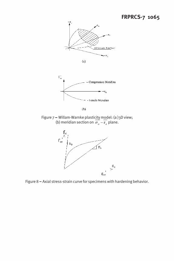
Modified Willam-Warnke (MWW) model for FRP-confined concrete
Prediction of the axial strength is based on the ultimate surface described by
Willam and Warnke (1975), as shown in Fig. 7(a); 1
σ , 2
σ , and 3
σ are the three stress
components. For FRP-confined concrete, 1
σ is taken as the axial compressive stress; 2
σ
and 3
σ represent the confining stress provided by the FRP composite in the two
transverse orthogonal directions. In plasticity theory the sign convention is that
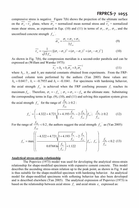
FRPRCS-7 1055compressive stress is negative. Figure 7(b) shows the projection of the ultimate surface
on the aa
τσ − plane, where a
σ = normalized mean normal stress and a
τ = normalized
mean shear stress, as expressed in Eqs. (10) and (11) in terms of 1
σ , 2
σ , 3
σ , and the
unconfined concrete strength '
co
f .
'
321
3co
a
f
σσσ
σ
++
= (9)
])()()[(
15
12
13
2
32
2
21'
σσσσσστ −+−+−=
co
a
f
(10)
As shown in Fig. 7(b), the compression meridian is a second-order parabola and can be
expressed as (Willam and Warnke 1975):
2
210 aaa
bbb σστ ++= (11)
where 0
b , 1
b , and 2
b are material constants obtained from experiments. From the FRP-
confined column tests performed by the authors (Yan 2005) these values are:
0417.00
=b , 7955.01
−=b and 1041.02
−=b . For specimens with hardening behavior,
the axial strength '
cc
f is achieved when the FRP confining pressure l
f reaches its
maximumlu
f . Therefore, '
1 cc
f−=σ ; lu
f−==
32
σσ at the ultimate state. Substituting
the corresponding terms in Eqs. (9), (10), and (11) and solving this equation system gives
the axial strength '
cc
f for the range of 2.0'
≥
co
lu
f
f
:
2.0;2193.41721.4322.4'
'
''
'
≥
−++−=
co
lu
co
co
lu
co
lu
cc
f
f
f
f
f
f
f
f (12)
For the range of 2.0
'
<
co
lu
f
f
, the authors suggest the axial strength '
cc
f as (Yan 2005):
2.0;,
122.1ln0768.0
2193.41721.4322.4
max'
''
'
''
'
<
+
−++−
=
co
lu
coco
co
lu
co
lu
co
lu
cc
f
f
ff
f
f
f
f
f
f
f (13)
Analytical stress-strain relationship
The Popovics (1973) model was used for developing the analytical stress-strain
relationship for shape-modified specimens with expansive cement concrete. This model
describes the ascending stress-strain relation up to the peak point, as shown in Fig. 8 and
is thus suitable for the shape-modified specimen with hardening behavior. An analytical
model for shape-modified specimens with softening behavior has also been developed
and is described elsewhere (Yan 2005). The analytical expression of Popovics (1973) is
based on the relationship between axial stress c
f and axial strain c
ε expressed as:
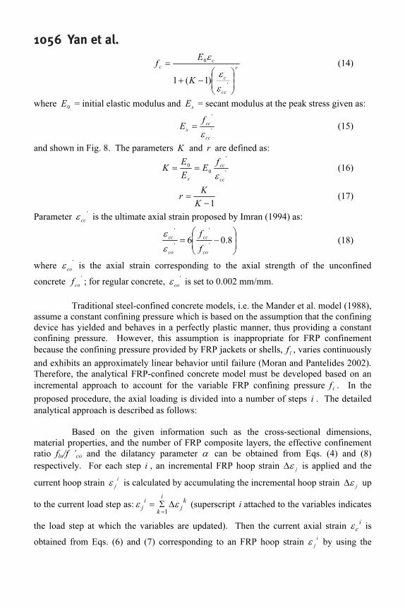
1056 Yan et al.
r
cc
c
c
c
K
E
f
−+
=
'
0
)1(1
ε
ε
ε
(14)
where 0
E = initial elastic modulus and s
E = secant modulus at the peak stress given as:
'
'
cc
cc
s
f
E
ε
= (15)
and shown in Fig. 8. The parameters K and r are defined as:
'
'
0
0
cc
cc
s
f
E
E
E
K
ε
== (16)
1−
=
K
K
r (17)
Parameter '
cc
ε is the ultimate axial strain proposed by Imran (1994) as:
−= 8.06'
'
'
'
co
cc
co
cc
f
f
ε
ε
(18)
where '
co
ε is the axial strain corresponding to the axial strength of the unconfined
concrete '
co
f ; for regular concrete, '
co
ε is set to 0.002 mm/mm.
Traditional steel-confined concrete models, i.e. the Mander et al. model (1988),
assume a constant confining pressure which is based on the assumption that the confining
device has yielded and behaves in a perfectly plastic manner, thus providing a constant
confining pressure. However, this assumption is inappropriate for FRP confinement
because the confining pressure provided by FRP jackets or shells,l
f , varies continuously
and exhibits an approximately linear behavior until failure (Moran and Pantelides 2002).
Therefore, the analytical FRP-confined concrete model must be developed based on an
incremental approach to account for the variable FRP confining pressurel
f . In the
proposed procedure, the axial loading is divided into a number of steps i . The detailed
analytical approach is described as follows:
Based on the given information such as the cross-sectional dimensions,
material properties, and the number of FRP composite layers, the effective confinement
ratio flu
/f ’co
and the dilatancy parameter α can be obtained from Eqs. (4) and (8)
respectively. For each step i , an incremental FRP hoop strain j
ε∆ is applied and the
current hoop strain i
jε is calculated by accumulating the incremental hoop strain
jε∆ up
to the current load step as:k
j
k
i
i
jεε ∆Σ=
=1
(superscript i attached to the variables indicates
the load step at which the variables are updated). Then the current axial strain i
cε is
obtained from Eqs. (6) and (7) corresponding to an FRP hoop strain i
jε by using the
FRPRCS-7 1057dilatancy parameter α . The confining pressure
i
l
f can be obtained from Eq. (3)
corresponding to an FRP hoop strain i
jε . Therefore, by setting
i
lluff = the maximum
axial stress, i
cc
f at i
jε can be calculated from the model of Eq. (12) for 2.0
'
≥
co
lu
f
f
or Eq
(13) for 2.0
'
<
co
lu
f
f
. The relationship between the current axial strain i
c
ε and axial stress
i
c
f , which corresponds to the current hoop straini
jε can be obtained by using the
Popovics model of Eqs. (14) - (18). The incremental steps are repeated until the hoop
strain i
jε reaches its ultimate state
juε =
fuk εε
, as shown in Eq. (4). For circular FRP
composite shells ε
k is set equal to 0.4; for elliptical shells, Eq. (5) should be used for
calculating ε
k .
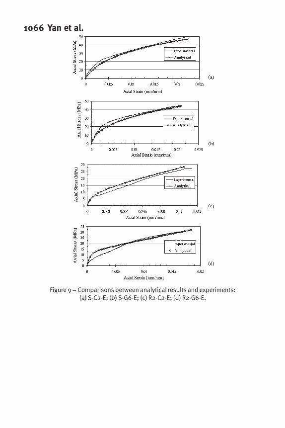
The incremental approach is easily implemented using a spreadsheet or any
computer program. Figure 9 shows comparisons between the analytical model and
experimental results; it can be seen that the analytical results agree well with the
experiments.
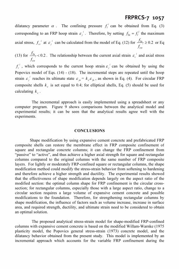
CONCLUSIONS
Shape modification by using expansive cement concrete and prefabricated FRP
composite shells can restore the membrane effect in FRP composite confinement of
square and rectangular concrete columns; it can change the FRP confinement from
“passive” to “active”, and thus achieve a higher axial strength for square and rectangular
columns compared to the original columns with the same number of FRP composite
layers. For lightly or moderately FRP-confined square or rectangular columns, the shape
modification method could modify the stress-strain behavior from softening to hardening
and therefore achieve a higher strength and ductility. The experimental results showed
that the effectiveness of shape modification depends largely on the aspect ratio of the
modified section: the optimal column shape for FRP confinement is the circular cross-
section; for rectangular columns, especially those with a large aspect ratio, change to a
circular section requires a large volume of expansive cement concrete and possible
modifications to the foundation. Therefore, for strengthening rectangular columns by
shape modification, the influence of factors such as volume increase, increase in surface
area, and required strength, ductility, and ultimate strain need to be considered to obtain
an optimal solution.
The proposed analytical stress-strain model for shape-modified FRP-confined
columns with expansive cement concrete is based on the modified Willam-Warnke (1975
plasticity model, the Popovics general stress-strain (1973) concrete model, and the
dilatancy behavior obtained from the present study. This model is implemented by an
incremental approach which accounts for the variable FRP confinement during the
1058 Yan et al.loading process. The analytical results show satisfactory agreement with the experiments
ACKNOWLEDGMENTS
The authors would like to acknowledge the contributions of FRP composite materials by
Sika and Air Logistics and the contribution of Type K cement and Komponent from CTS
Company. The financial support provided by the Utah Department of Transportation is
also acknowledged.
REFERENCES
Benuska, K. L., Bertero, V. V., and Polivka, M. (1971). “Self-Stressed Concrete for
Precast Building Units.” PCI Journal, March-April 1971, 72-84.
Imran, I. (1994). “Application of Non-Associated Plasticity in Modeling the Mechanical
Response of Concrete.” Ph.D. Dissertation, University of Toronto, 1994.
Klein, A., Karby, T., and Polivka, M. (1961). “Properties of An Expansive Cement for
Chemical post-tensioning.” ACI Journal, Proceedings, Vol. 58, No. 1, July 1961, 59-82.
Moran, D. A., and Pantelides, C. P. (2002). “Variable Strain Ductility Ratio for Fiber
Reinforced Polymer-Confined Concrete.” Journal of Composites for Construction,
ASCE, 2002, 6(4), 224-232.
Pessiki, S., Harries, K. A., Kestner, J. T., Sause, R., and Ricles, J. M. (2001). "Axial
Behavior of Reinforced Concrete Columns Confined with FRP Jackets." Journal of
Composites for Construction, ASCE, 2001, 5(4), 237-245.
Popovics, S. (1973). "Numerical Approach to the Complete Stress-Strain Relation for
Concrete." Cement Concrete, 1973, 3(5), 583-99.
Rochette, P., and Labossière, P. (2000). "Axial Testing of Rectangular Column Models
Confined with Composites." Journal of Composites for Construction, ASCE, 2000, 4(3),
129-136.
Willam, K. J., and Warnke, E. P. (1975). “Constitutive Model for the Triaxial Behavior
of Concrete.” Proceedings, International Association for Bridge and Structural
Engineering, Vol. 19, 1-30.
Yan, Z. (2005). “Shape Modification of Rectangular Columns Confined with FRP
Composites.” Ph.D. Dissertation, Department of Civil and Environmental Engineering,
University of Utah, Salt Lake City, Utah, May 2005.
FRPRCS-7 1059
1060 Yan et al.
FRPRCS-7 1061
Figure 1 – – – – – Expansion history for FRP shells with expansive cement concrete:(a) Square S; (b) Rectangular R2; (c) Rectangular R3.
Figure 2 – – – – – Relationship between aspect ratio j
j
D
B
and initial hoop strain inij ,ε .
1062 Yan et al.
Figure 3 – – – – – Typical failure modes for FRP-confined specimens:(a) without shape modification; (b) with shape modification.
Figure 4 – – – – – Axial stress-strain curves for CFRP-confined columns:(a) Square S; (b) Rectangular R2; (c) Rectangular R3.
FRPRCS-7 1063
Figure 5 – – – – – Axial stress-strain curves for GFRP-confined columns:(a) Square S; (b) Rectangular R2; (c) Rectangular R3.
1064 Yan et al.
Figure 6 – – – – – Volumetric versus axial strain relationships for shape-modified specimenswith expansive cement concrete.
FRPRCS-7 1065
Figure 7 – – – – – Willam-Warnke plasticity model: (a )3D view;(b) meridian section on
aaτσ − plane.
Figure 8 – – – – – Axial stress-strain curve for specimens with hardening behavior.
1066 Yan et al.
Figure 9 – – – – – Comparisons between analytical results and experiments:(a) S-C2-E; (b) S-G6-E; (c) R2-C2-E; (d) R2-G6-E.