Embed Size (px)
Citation preview
DEPARTMENT OF COMMERCEBUREAU OF STANDARDSCeorge K. Burgess, Director
TECHNOLOGIC PAPERS OF THE BUREAU OF STANDARDS, No. 258
[Part of Vol. 18]
STRENGTH OF STEEL TUBING UNDER
COMBINED COLUMN AND TRANSVERSE
LOADING, INCLUDING TESTS OF
COLUMNS AND BEAMS
BY
TOM W. GREENE, Assistant Engineer Physicist
Bureau of Standards
May 23, 192.4
PRICE, 15 CENTS
$1.25 PER VOLUME ON SUBSCRIPTION
Sold only by the Superintendent of Documents, Government Printing Office
Washington, D. C.
WASHINGTONGOVERNMENT PRINTING OFFICE
1924
STRENGTH OF STEEL TUBING UNDER COMBINEDCOLUMN AND TRANSVERSE LOADING, INCLUDINGTESTS OF COLUMNS AND BEAMS.
By Tom W. Greene.
ABSTRACT.
This investigation was made for the purpose of determining whether experimental
data confirmed the theory of struts subjected to combined column and transverse
loading. A number of tests were made on steel-tubing struts ranging from that of a
column with no transverse load to that of a beam with no column load.
A study was made of the conditions contributing to the strength of a strut and a
method devised for measuring eccentricity. It was found that the eccentricity due
to variation in wall thickness and to deviation from straightness is an important
factor and should be taken into account. The results show that the commonly used
formulas, which neglect the effect of eccentricity of loading, do not represent actual
strut condition and are liable to give dangerously high results.
A modified rational formula based upon consideration of the effect of eccentricity
was found to fit experimental results very closely and is the preferable one for design.
Failure of a strut will occur when the maximum compressive stress computed by this
modified formula is approximately equal to the yield point. The modified rational
formula also applies to columns as it reduces to the "secant" column formula whenthe transverse load is equated to zero. Failure of a column will occur when the
extreme fiber stress computed by the'
' secant'
' formula is equal to the yield point of
the material.
A reasonably accurate computation of the stress for a strut under transverse load
can be made by summing the bending stress due to the transverse load and the column
stress obtained by the "secant" formula if for the latter the effective eccentricity is
taken as the sum of the original eccentricity, due to tube irregularities, and the deflec-
tion of the strut at the center resulting from the transverse load.
CONTENTS.Page.
I. Introduction 244
1
.
Purpose of the investigation 244
2
.
Acknowledgments 244
II. Test procedure 244
1. Physical properties of the material 244
2
.
Beam tests 248
3
.
Column tests 249
4. Combined column and transverse tests 249
III. Results of strut tests , 2 50
IV. Theory and application of formulas 256
1. Application of formulas for combined loading 256
2. Modified rational formula for combined loading 260
3. Eccentricities 262
43
244 Technologic Papers of the Bureau of Standards [Vol. is
IV. Theory and application of formulas—Continued.
3. Eccentricities—Continued.
(a) Causes of eccentricity 262
(b) Determination of eccentricity 262
1. Eccentricity due to variation in wall thickness 262
2. Eccentricity due to deviation from straightness . .
.
264
(c) Discussion 265
(d) Accuracy of method of determining eccentricity 268
4. Application of modified rational formula 269
5. Application of "secant' ' column formula 271
(a) To columns 271
(b) To struts with transverse loading 272
V. Conclusions 275
VI. Recommendations 276
I. INTRODUCTION.
1. PURPOSE OF THE INVESTIGATION.
In airplane construction there are many members, such as
struts, which are subjected to a lateral or transverse loading in
addition to an axial or column loading. This investigation was
made at the request of the Bureau of Aeronautics, Navy Depart-
ment, for the purpose of determining whether experimental data
confirmed the approximate theory of struts subjected to com-
bined axial and transverse forces or whether it would be necessary
to devise new formulas.
A large number of tests were made on steel-tubing struts of
different lengths with various intensities of transverse loading.
The tests included different ratios of direct compression to trans-
verse loading, ranging from that of a column with no transverse
load to that of a beam with no column load.
2. ACKNOWLEDGMENTS.
The funds and material for this investigation were furnished bythe Bureau of Aeronautics, Navy Department. Acknowledg-
ments are also due Lieut. C. J. McCarthy, Bureau of Aeronautics,
for his assistance, cooperation, and suggestions.
II. TEST PROCEDURE.
1. PHYSICAL PROPERTIES OF THE MATERIAL.
Steel tubing made in England of i^-inch diameter, 20 gauge,
and 1 ]/2 -inch diameter, 16 gauge, was used for all struts and beamsin this investigation. The physical properties of the material
were accurately determined by tensile and compression tests of
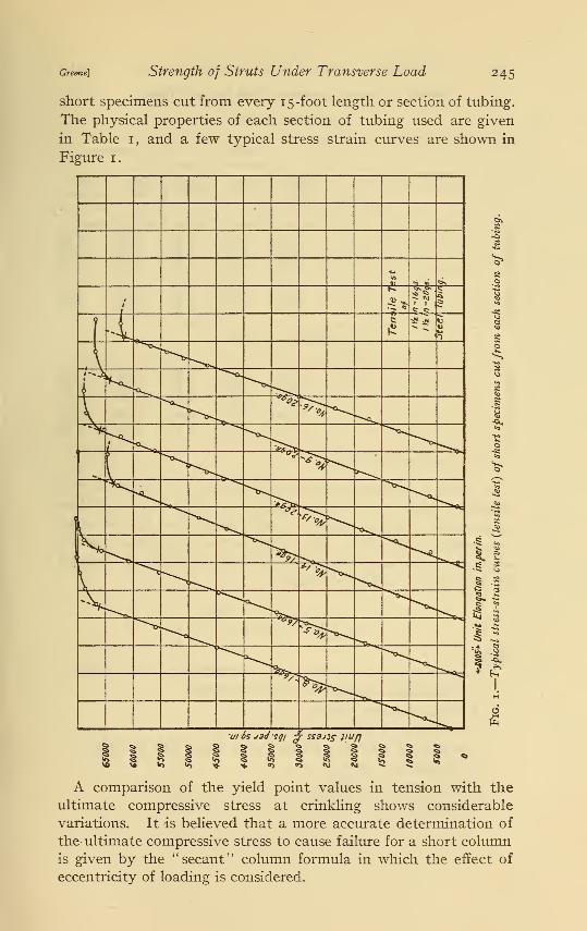
Greene] Strength of Struts Under Transverse Load 245
short specimens cut from every 15 -foot length or section of tubing.
The physical properties of each section of tubing used are given
in Table 1 , and a few typical stress strain curves are shown in
Figure 1.
^ <s <i <a *i S % I 3 §§ 5 1 § ? 5
A comparison of the yield point values in tension with the
ultimate compressive stress at crinkling shows considerable
variations. It is believed that a more accurate determination of
the- ultimate compressive stress to cause failure for a short column
is given by the "secant" column formula in which the effect of
eccentricity of loading is considered.
246 Technologic Papers of the Bureau of Standards
TABLE 1.—Physical Properties of Each Section of Tubing.
[Vol. 18
VA INCHES, 20 GAUGE.
Tension. Compression.!
Section number.Propor-tionallimit.
Yieldpoint.
Ultimatestrength.
Propor-tionallimit.
Ultimatestress
(crinkling).
7
Lbs./in.*66,00064, 000
66, 00067, 50066,000
64,00054, 00059, 00061,500
Lbs./in.»
72, 100
69, 90068, 90069, 00067, 400
66, 80063, 40061,20062, 200
Lbs./in. 2
78, 90076, 40074, 90074,00073, 400
73, 40070,80069, 60068, 700
Lbs./in.*58,50054,00056,50058,00056,000
56,00053,00053, 50052,600
Lbs./in.*67 700
15 65 80013 65,00011.... 64,80017 68,400
64,8009
4 65,2001 59,00016 66,200
VA INCHES, 16 GAUGE.
3 67,00066, 00066,00065,000
62,00063,50059,000
71,30070, 200
70, 00069,100
67,50064,60061,300
75, 30074, 60073, 800
73,400
71,40069, 60067, 100
59,00054, 00055, 00055, 000
54,00051,00051,000
75,5008 71,8005 67,8009 69,500
7 67,40014 65,30010 65,800
1 L/r= 10 for short compression specimens.
In Table 2 are given the eccentricities due to variation in wall
thickness, which will be explained later, and the effect of these
eccentricities on the ultimate compressive stress for the short
compression specimens. The values in the last column are the
ultimate or maximum compressive stresses at failure Sc obtained
by the "secant" column formula,
-5(,
ec1 + -5 sec
VSr/)where
e = eccentricity in inches due to variation in wall thickness,
P =maximum compressive load in pounds,
A = area in square inches,
r = radius of gyration in inches,
c = distance from neutral axis to extreme fiber in inches,
L — length in inches,
/ = moment of inertia,
E = modulus of elasticity (29,000,000 lbs./in.2).
Greene) Strength of Struts Under Transverse Load 247
TABLE 2.—Ultimate or Maximum Compressive Stresses for Short CompressionSpecimens.
VA INCHES, 20 GAUGE.
Section number.Variation inthickness of
wall.
Eccen-tricity.
c
Ultimatecompres-sive stressat failure.
5c 1
15...
Inches.0. 0325-0. 035
. 033 - . 037
. 0325- . 035.035
. 0345- . 0355.035
. 034 - . 040.036
Inches.0. 0153.022.014.000
.0083
.000
.032
.000
Lbs./in.268,800
13 69,30011 67,600172. 68,400
9 66,40042 65,200
64,70016 2 66,200
VA INCHES, 16 GAUGE.
3 0. 059 -0. 066. 0595- . 064. 059 - . 066. 060 - . 063. 061 - . 067
0. 0215.014.0215.0095.018
80, 400
8 74,8005 71,6007 69,30014 68,800
P / ec I PL2 \1Se=-j ( iH—2 sec-\/
~~Wj ) where e is eccentricity due to variation in wall thickness and P is the maxi-
mum compressive load (crinkling).2 Short compressive specimens crinkled near end.
It will be seen that for tubes with eccentricity of loading the
values for the ultimate stress in compression are raised and
approximate very closely the yield point of the material in ten-
sion. Although the "secant" column formula is not exact above
the proportional limit, it is believed that for the material used,
in which the proportional limit and yield point are nearly the
same, the ultimate compressive stress value Sc in the table is
probably the yield point in compression and represents very
closely the stress to cause failure in compression for any strut cut
from these sections.
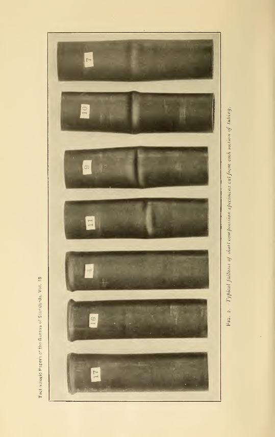
The effect of eccentricity is also indicated in the type of failure
for the short columns. In specimens Nos. 17, 4, and 16, where
the eccentricities were zero, the specimens failed by crinkling
near the ends. In the other short columns the crinkling occurred
on the thin side at the center where the maximum compressive
stress occurs from bending due to the eccentricities. Figure 2
shows a few of the typical failures.
248 Technologic Papers of the Bureau of Standards
2. BEAM TESTS.
[Vol. 18
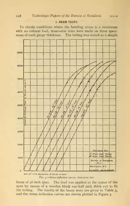
To obtain conditions where the bending stress is a maximumwith no column load, transverse tests were made on three speci-
mens of each gauge thickness. The tubing was tested as a simple
30060
90000
70000
40000
50000
4 0000
30000
eoooo
10000
*— 0.1 '
' » Deflect ien at center 0/ span
Fig. 3.
—
Stress-deflection curves, transverse test.
beam of 36-inch span. The load was applied at the center of the
span by means of a wooden block one-half inch thick cut to fit
the tubing. The results of the beam tests are given in Table 3,
and the stress deflection curves are shown plotted in Figure 3.
"t3
5
oq
Greene) Strength of Struts Under Transverse Load
TABLE 3.—Beam Test (Span 36 Inches).
249
13^ INCHES, 20 GAUGE.
Specimennumber.
Variation inthickness 0!
wall.Area.
Momentof inertia.
/
Sectionalmodulus.
Je
Propor-tional
limit.
Modulusof rupture.
Modulus of
elasticity.
15-BInches.
0. 032-0. 035.033- .035.035- .037
Sq. inch.0. 1566.1566.1656
In.<
0.0421.0421.0444
In.3
0. 0562.0562.0592
Lbs./in.»
64,00070,00065,000
Lbs./in.*
88,08085,67082,080
Lbs./in.«
28, 400, 000
29, 020, 00011-B16-B 29, 140, 000
1J4 INCHES, 16 GAUGE.
8-B..5-B..10-B.
0.061-0.063 C. 2803 0. 0725 0. 0966 61,000 92,600.061- .065 .2846 .0735 .0980 68,000 91,800.062- .064 .2846 .0735 .0980 62,000 83,560
28,080,00027, 500, 00028, 080, 000
3. COLUMN TESTS.
Some of the tubes were tested as round end columns without
transverse loading. Free end conditions were insured by special
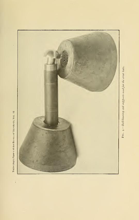
ball-bearing end supports. Figure 4 shows the ball-bearing endsupports used for all the compression tests. The small balls
minimized the frictional resistance developed during the loading
of the struts and permitted the struts to deflect freely in anydirection, thus approaching ideal "free end" conditions.
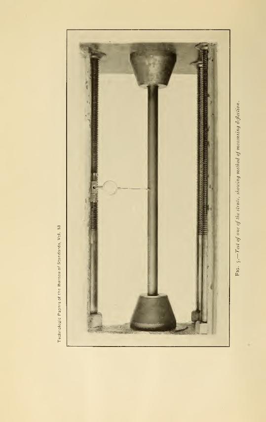
4. COMBINED COLUMN AND TRANSVERSE TESTS.
The tube was mounted as in the column test for the combinedbeam and column tests. These tests were made in a horizontal
position in an Emery hydraulic testing machine. Extreme care
and precaution was exercised in the application of the side load.
A small initial end load was first applied to the strut. The trans-
verse load was then applied. For uniform transverse loads of 1,
5, io, tand 20 pounds per linear inch weights of 1, 5, 10, and 20
pounds, respectively, were suspended 1 inch apart throughout
the length of the struts. For loads of 1.25, 3, and 6.05 poundsper linear inch weights were suspended in bags attached to the
tubing. Thus, a very uniform distribution of lateral loading wasobtained in all the tests.
Measurements of the original straightness of the tubes and of
the vertical deflection under load at the mid length of the test
piece were taken for all the tests by means of a micrometer dial
reading directly to 0.00 1 inch. Figure 5 shows the test of one of
the struts and the method of measurements.
90893°—24 2
250 Technologic Papers of the Bureau of Standards
III. RESULTS OF STRUT TESTS.
[Vol. 18
The number assigned to the struts tested in this investigation,
together with the length, Ljr ratio, kind of test, the transverse
load, and properties, are given in Table 4. The dimensions of
each strut tested were determined from a large number of microme-
ter measurements of wall thickness made at each end. Measure-
ments of the end sections showed that while the wall thickness
was quite variable (see Table 4) it was practically the same for
corresponding points at the two ends of a tube, so that the endmeasurements fairly represent the wall thickness throughout the
length of a strut.
The ultimate loads of the columns and of the struts with trans-
verse loading are given in Table 5 . The table also includes the effect
of the transverse loading ; that is, the bending stress, the computedand measured deflection at the center of the strut produced by
the transverse load alone.
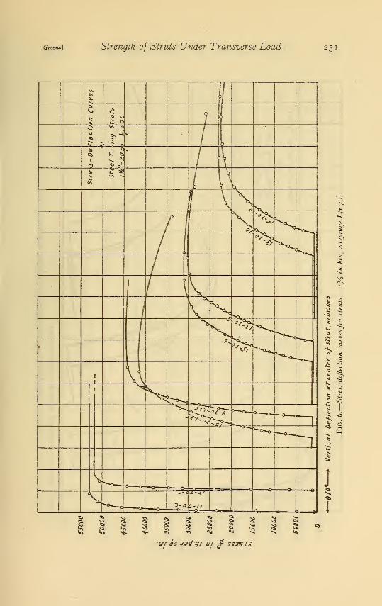
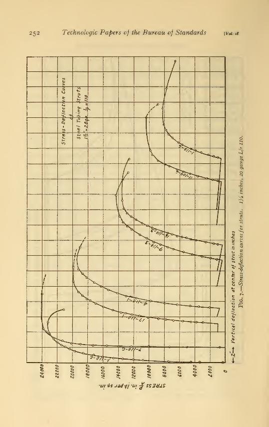
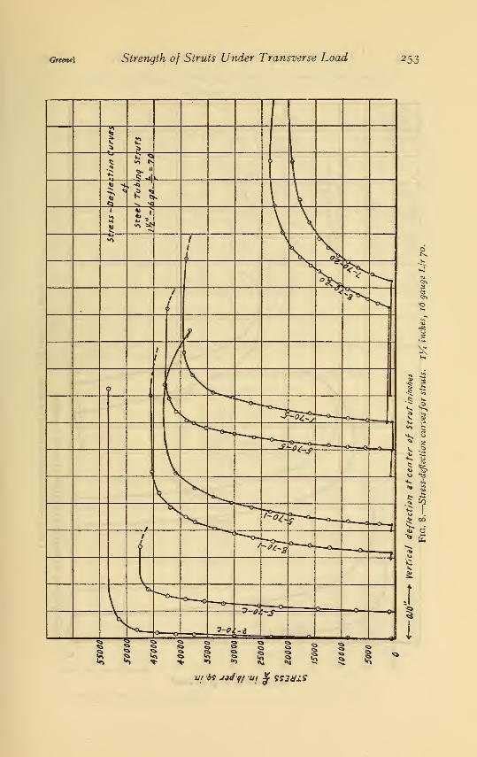
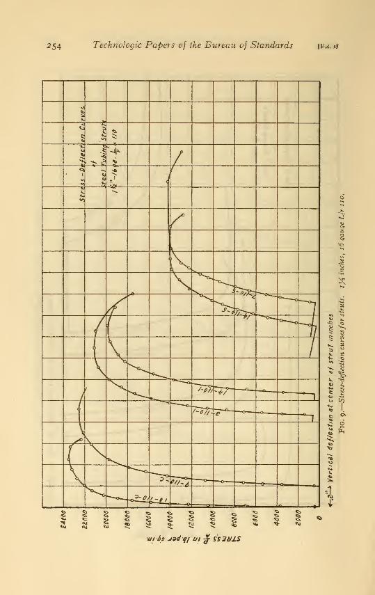
The stress-deflection curves for the struts are shown in Figures
6 to 9, inclusive. The effect of increasing the transverse loading
in decreasing the column strength and increasing the rate of
deflection are shown in these curves.
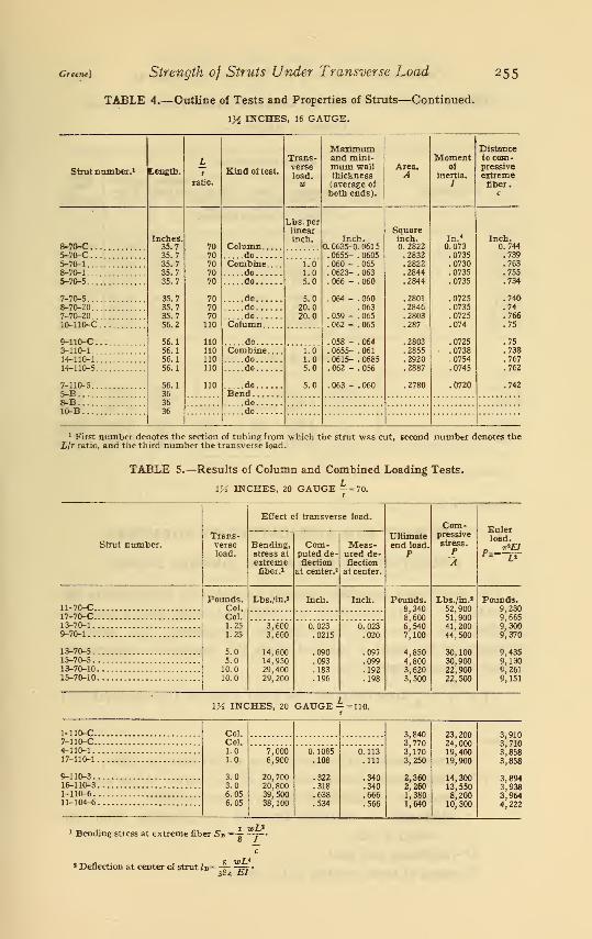
TABLE 4.—Outline of Tests and Properties of Struts.
1H INCHES. 20 GAUGE.
Strut number. 1 Length.Lt
ratio.
Kind at test.
Trans-verseload.
w
Maximumand mini-mum wallthickness(average of
both ends).
Area.A
Momentof
Inertia.
/
Distanceto com-pressiveextremefiber.
c
11-70-CInches.
36.336.336.236.236.3
36.336.236.25757
5757575757
53.8363636
7070707070
707070110110
110110110110110
104
Column
Lbs. perlinearinch. Inch.
0. 035 -0. 0335. 0365- . 0355. 034 - . 036. 034 - . 035. 033 - . 037
. 0325- . 035
. 033 - . 036
. 034 - . 0337
. 034 - . 038
. 032 - . 036
. 035 - . 036
. 036 - . 035
. 0355- . 036
. 035 - . 0375
. 0393- . 0337
.0345
Squareinch.0. 1577.1656.1588.1597.1611
.1552
.1579
.1556
.1656
.1566
.1633
.1633
.1647
.1667
.1678
.1588
In.*0.0424.0444.0427.0429.0432
.0418
.0424
.0419
.0444
.0421
.0438
.0438
.0442
.0447
.0450
.0427
Inch.0.743
17_70_C doCombine
dodo
dododo
Column
'
"i.'251.255.0
5.010.010.0
.745
13-70-1 .759-70-1 .75513-70-5 .770
15-70-5 .76413-70-10 .76315-70-10 .749
1-110-C .757-110-C .do .75
4-110-1 Combinedodododo
doBend
1.01.03.03.06.05
6.05
.75517-110-1 .7459-110-3 .75216-110-3 .7631-110-6 .723
11-104-6 .7515-B11-B do16-B do...
1 First number denotes the section of tubing from which the strut was cut, second number denotes theLjr ratio, and the third number the transverse load.
Greene] Strength of Struts Under Transverse Load 251
ft
•Uf6sJ9d-q/ ft/ £ SS3VAZ
252 Technologic Papers of the Bureau o) Standards [Vd. 18
'Ut b$ j*dyj to £ SSJ&JLS
Greene] Strength of Struts Under Transverse Load 253
ui bi J3<Jff ui £ g?j#x$"
254 Technologic Papers of the Bureau of Standards [Vol. is
tit Si U9dqf ui £ SS3V1S
Greene] Strength of Struts Under Transverse Load 255
TABLE 4.—Outline of Tests and Properties of Stmts—Continued.
1}4 INCHES, 16 GAUGE.
Strut number. 1 Length.Ir
ratio.
Kind of test.
Trans-verseload.w
Maximumand mini-mum wallthickness(average of
both ends).
Area.A
Momentof
inertia./
Distanceto com-pressiveextremefiber.
c
8-70-CInches.
35.735.735.735.735.7
35.735.735.756.2
56.156.156.156.1
56.1363636
7070707070
707070110
110110110110
110
Column
Lbs. perlinearinch. Inch.
0.0635-0. 061
5
. 0655- . 0605
. 060 - . 065
. 0623- . 063
. 066 - . 060
. 064 - . 060.063
. 059 - . 065
. 062 - . 065
. 058 - . 064
. 0655- . 061
. 0615- . 0685
. 062 - . 056
. 063 - . 060
Squareinch.0. 2822.2832.2822.2844.2844
.2801
.2846
.2803
.287
.2803
.2855
.2920
.2887
.2780
In. 4
0.073.0735.0730.0735.0735
.0725
.0735
.0725
.074
.0725
. 0738
.0754
.0745
.0720
Inch.0.744
5-70-C doCombine
dodo
dododo
Column
""i'.o1.05.0
5.020.020.0
.7395-70-1 .7638-70-1 .7555-70-5 .734
7-70-5 .7408-70-20.
. .
.
.747-70-20 .76610-110-C .75
9-110-C doCombine
dodo
doBend
""i.'o"1.05.0
5.0
.753-110-1 .73814-110-1 .76714-110-5 .762
7-110-5 .7425-B...8-B .. ..do10-B do ..
1 First number denotes the section of tubing from which the strut was cut, second number denotes the£/r ratio, and the third number the transverse load.
TABLE 5.—Results of Column and Combined Loading Tests.
VA INCHES, 20 GAUGE —-70.
Trans-verseload.
Effect of transverse load.
Ultimateend load.
P
Com-pressivestress.
PA
Strut number. Bending,stress at
extremefiber.i
Com-puted de-flection
at center.2
Meas-ured de-flection
at center.
load.TfiEl
Pk jy
11-70-CPounds.
Col.Col.1.251.25
5.05.010.010.0
Lbs./in.» Inch. Inch. Pounds.8,3408,6006,5407,100
4,8504,8003,6203,500
Lbs./in.»
52,90051,90041,20044,500
30,10030,90022,90022,500
Pounds.9,230
17-70-C 9,6659,3009 370
13-70-1 3,6003, 600
14,60014,95029,40029, 200
0.023.0215
.090
.093
.183
.196
0.023.020
.097
.099
.192
.198
9-70-1
13-70-5 9,4359,1309 261
15-70-513-70-1015-70-10 9,151
INCHES, 20 GAUGE =110.
1-110-C.7-110-C.4-110-1
.
17-110-1
9-110-3.16-110-31-110-6.11-104-6
Col.CoL1.01.0
3.03.06.056.05
7,0006,900
20,70020,80039, 50038,100
0. 1085
.322
.318
.638
.534
0.113.111
.340
.340
.666
.566
3,8403,7703,1703,250
2,3602,2601,3801,640
23,20024,00019,40019,900
14,30013,5508,20010,300
3,9103,7103,8583,858
3,8943,9383,9644,222
1 Bending stress at extreme fiber S-b ==-jt—j~-
* Deflection at center of strut JB=~— •
384 h.1
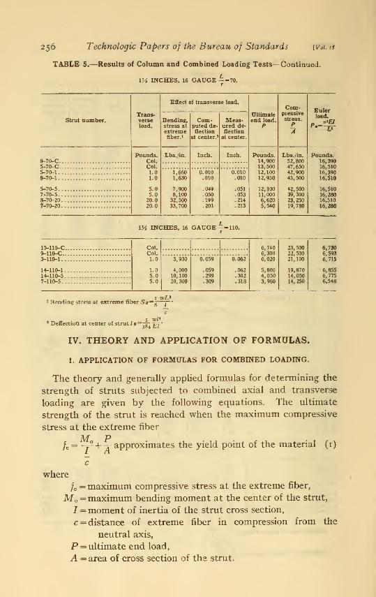
256 Technologic Papers of the Bureau of Standards ivoi. 18
TABLE 5.—Results of Column and Combined Loading Tests—Continued.
VA INCHES, 16 GAUGE --70.
Trans-verseload.
Effect of transverse load.
Ultimateend load.
P
Com-pressivestress.
PA
Strut number. Bending,stress at
extremefiber.i
Com-puted de-flection
at center. 2
Meas-ured de-flection
at center.
load.
8-70-CPounds.
Col.Col.1.01.0
5.05.020.020.0
Lbs./in. Inch. Inch. Pounds.14,90013,50012,10012,950
12,10011,0006,6205,540
Lbs./in.
52, 80047,65042,90045,500
42,50039,30023,25019,780
Pounds.16,39016,51016,39016,510
16,51016,28016,510
5-70-C5-70-1 1,660
1,630
7,9008,10032,50033,700
0.010.010
.049
.050
.199
.201
o.oio.010
.051
.053
.214
.213
8-70-1
5-70-57-70-58-70-207-70-20 16,280
iy3 INCHES, 16 GAUGE 110.
10-110-C.9-110-C..3-110-1..
14-110-1.14-110-5.7-110-5.
Col.Col.1.0
1.05.05.0
6,7406,3006,020
5,8004,0503,960
23,50022,50021,100
19,87014,05014,250
3,930
4,00010,10020,300
0.059
.059
.299
.309
6.062
.062
.302
.318
6,7306,5936,715
6,8556,7756,548
i wL*Bending stress at extreme fiber Sb=^—j~
'
5 wl*1 Deflection at center of strut * »= I^: /FT
'
IV. THEORY AND APPLICATION OF FORMULAS.
1. APPLICATION OF FORMULAS FOR COMBINED LOADING.
The theory and generally applied formulas for determining the
strength of struts subjected to combined axial and transverse
loading are given by the following equations. The ultimate
strength of the strut is reached when the maximum compressive
stress at the extreme fiber
fc= -j2- + -j approximates the yield point of the material (i)
where
/c = maximum compressive stress at the extreme fiber,
M =maximum bending moment at the center of the strut,
J = moment of inertia of the strut cross section,
c = distance of extreme fiber in compression from the
neutral axis,
P = ultimate end load,
A = area of cross section of the strut.
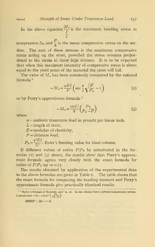
Greene) Strength of Struts Under Transverse Load 257
In the above equation -y2 is the maximum bending stress in
c
pcompression 5b, and -x- is the mean compressive stress on the sec-
tion. The sum of these stresses is the maximum compressive
stress acting on the strut, provided the stress remains propor-
tional to the strain at these high stresses. It is to be expected
that when this maximum intensity of compressive stress is about
equal to the yield point of the material the strut will fail.
The value of M Q has been commonly computed by the rational
formula '
.. WEI / 7T [P \ , .-M =--p~ (KC^p- -I)
(2)
or by Perry's approximate formula *
iwL2
M„ = pfb) «8
where
w = uniform transverse load in pounds per linear inch,
L = length of strut,
E = modulus of elasticity,
P = ultimate load,
7T2EI
Pe =j 2
> Euler's limiting value for ideal column.
If different values of ratios P/Pe be substituted in the for-
mulas (2) and (3) above, the results show that Perry's approxi-
mate formula agrees very closely with the exact formula for
ratios of P/PE up to 0.75.
The results obtained by application of the experimental data
to the above formulas are given in Table 6. The table shows that
the exact formula for computing the bending moment and Perry's
approximate formula give practically identical results.
1 "Morley's Strength of Materials, 1916," p. 282. In this edition Perry's formula is incorrectly written.
Itshouldread,-Mo=i/8wL2 (p^p)90893°—24 3
258 Technologic Papers of the Bureau of Standards \Voi. 18
TABLE 6.—Results by Commonly Used Formulas for Combined Loading.
IV2 INCHES, 20 GAUGE -=70.
Trans-verseload.
Exact formula. Perry's formula.
Ratio.5B/o
Strut number.
Maximum
—
Yieldpoint of
Bendingstress. 1
5B
Com-pressivestress. 3
Bendingstress. 3
5B
Com-pressivestress. 3
/c
material(tension).
13-70-1Pounds.
1.251.255.05.0
10.010.0
Lbs./in.3
12,35015,10030, 45032,00048,70048,300
Lbs./in.3
53, 55059,60060, 55062,90071,60070, 800
Lbs./in.3
12,10014,90030, 05031,50048,30047, 400
Lbs./in.3
53, 300
59, 40060,15062,40071,20069, 900
0.227.25.50.505.68.68
Lbs./in. 3
68,90066,80068,90069,90068,900
9-70-113-70-515_70_513-70-1015-70-10 69,900
INCHES, 20 GAUGE
4-110-1 1.01.03.03.06.056.05
39, 60044,87053, 30049, 57061,16063,200
59,10064,77067,60063,00069,36073, 500
39, 300
43, 80052,70048,80060,60062,900
58,70063,70067,00062,35068,80073.200
0.67.68.78.78.88.86
63,40067,40066,80062,20061,200
17-110-19-110-316-110-31-110-611-104-6 69,000
Wi INCHES, 16 GAUGE -=70.
5-70-1.8-70-1.5-70-5.7-70-5.8-70-207-70-20
1.0 6,500 49,400 6,400 49, 300 0.131.0 7,740 53,200 7,600 53,100 .145.0 30, 300 72,800 29, 500 72, 000 .415.0 25, 600 64,900 25,030 64,350 .39
20.0 54,400 77 650 54,200 77,450 .7020.0 51,900 71,670 51,000 70,800 .72
70,00070,20070,00067, 50070,20067,500
Wi INCHES, 16 GAUGE : 110.
3-110-1 - ..' 1.0
1.05.05.0
38, 30026,55050,94052,290
59, 40046,42065,00066, 540
38,00025,95050.10051,300
59, 10045, 80064,15065,600
0.64.57.78.78
71,300
14-110-1. . 64,600
14-110-5. . 64,600
7-110-5 67,500
. _ Moc wEc ( * f~P \
fc~7 +Ac
A comparison of the maximum compressive stress values at
failure, obtained by the commonly used formulas for struts with
transverse loading with the yield point of the material, shows
extreme inconsistency and wide variation. This variation is
shown graphically in the left half of Figure 10. In this figure the
maximum compressive stresses at failure computed by either of
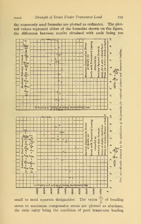
Greene] Strength of Struts Under Transverse Load 259
the commonly used formulas are plotted as ordinates. The plot-
ted values represent either of the formulas shown on the figure,
the difference between results obtained with each being too
-co -ere as:— **\*> I
2
£>s * 2 5 s -£
11-ft.
s $ * 1
I* 1 1 .? U
N D
Al
1^
^ +
*kn
8°
&1
5
s
63
Vi os J90 f/lu 1 1/0/ IPJ IP±Sr*
JK 3/ fSi SJC UJO0*ew
"S
a
Wii/F "S
<tfjs*
-03]-e-t*eey
%
B "> .$»"5
Si - 1 5 -
i* * i 5 ^5s *s s 5 5
n
—
4
s + +
| « »
« II
cc00
c
c )
c
°c
G5
s
3
Ivy/ is-. 30
h
7 u K sjnnej p SSi 995 31 J f?=u4 WJ 'XB[ V
S }
small to need separate designation. The ratios ~ of bendingh
stress to maximum compressive stress are plotted as abscissas,
the ratio unity being the condition of pure transverse loading
260 Technologic Papers of the Bureau of Standards \voi. 18
(modulus of rupture) and the axis of coordinate values o.o repre-
senting pure compression on short lengths. The maximum com-pressive stress (ordinate values) for the latter are practically the
yield-point values obtained by tensile tests of the material.
This figure shows that the commonly used formulas do not
accurately determine the load which will cause failure. For a
large number of the tests, especially for short struts and for struts
with small transverse load, these formulas give dangerously high
values and should not be used for design.
The wide variation of the results and the possible danger in
applying these formulas lead to a very detailed study of the con-
ditions contributing to the strength of struts. A modified rational
formula was found that will more accurately and safely represent
stress conditions of struts subjected to combined axial and trans-
verse loading.
2. MODIFIED RATIONAL FORMULA FOR COMBINED LOADING.
Let L be the length of a round or free end column carrying a
transverse load of w pounds per unit length. The end load Phas an eccentricity e relative to the centroidal axis of the column.
Assume the ©rigin O midway between the ends, the line joining
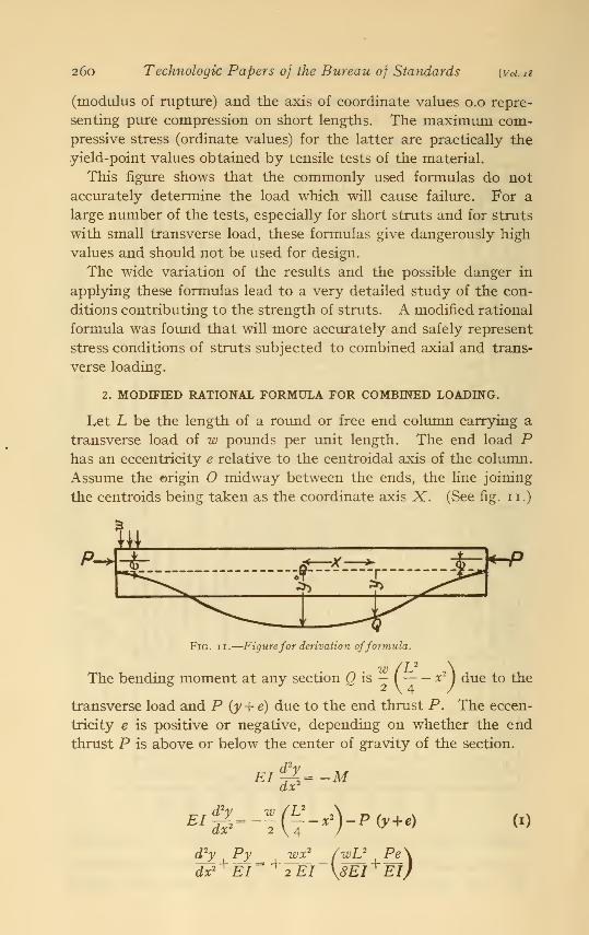
the centroids being taken as the coordinate axis X. (See fig. II.)
kzs
Fig. ii.—Figurefor derivation offormula.
W (U \The bending moment at any section Q is - ( x 2
Jdue to the
transverse load and P (y + e) due to the end thrust P. The eccen-
tricity e is positive or negative, depending on whether the end
thrust P is above or below the center of gravity of the section.
3--" (?-*)-**« ">EI .
4
<Py ,Py__ t^*2
dx*+ EI~"*"2EI
(wV Pe\\8ErEl)
Greene) Strength of Struts Under Transverse Load 261
The solution of this differential equation is
wx2 wL2 wEI .. / P _ . / Py-^P~w~-p2
-- e+Acos ^m x+Bsm \Ei x '
The condition ~- = O for x = and y = for x = — gives B =0ax 2
. (wEI \ L [~P
hence,
wx* wU wEI r/wEI \ L fP [P~ 1
y-^p-w—w -' +[v-p^
+v 9ec2 yiEi^vm*]
and at the origin or point of maximum moment where * =
tvU (WEI \( L fPX .»
The maximum moment at is
-M.-P(y. + e)+iwL' (3)
-M„ =Pc-[^ + Pe
][1 -sec \ ^]
'
-1 T /P" TOE// 7T /P \-M =Pe sec - y^ + -p~ (sec - y/p-^l)
IT2EI
where Pe = —ft~> Euler's limiting value for ideal column.
(4)
Therefore, to cause failure of a strut subjected to combined
column and transverse loading, the maximum compressive stress
at the extreme fiber is
UI_+ A
c
approximates the yield point of the material, or
' P Pec it IP wEc / it fP \h-j + -Y sec -
% yp£+^ (sec - fa-i) (5)
•See Church's Mechanics of Engineering, p. 382; 1908.
262 Technologic Papers of the Bureau of Standards [Vol. is
An examination of formula (4) for the bending moment shows
that the first term takes account of the bending moment due to
the eccentricity of the end load, and that the second term is the
expression for a column with a transverse load combined with an
axial end load. The formula also explains why the two commonlyused formulas are undesirable for short struts and struts with
small side loads. For short struts the end load P is very large, so
7T l~Pthat for a given eccentricity the factor Pe sec - •% / p- becomes a very
large and important factor in computing the bending moment and
consequently the bending stress. Also, when w is small this factor
is relatively large and important. On the other hand, when the
struts are long P is very small, making the factor Pe relatively
less important. Likewise, when the transverse load w is large, the
second factor of the formula is large, and the eccentric factor has
a relatively less influence on the strength of a strut.
3. ECCENTRICITIES.
(a) CAUSES OF ECCENTRICITY.
The modified rational formula indicates the importance of
eccentricities. Such eccentricities are chiefly caused by the fol-
lowing conditions found in commercial tubing: (1) Deviation of
the shape of the tubing from a circular section, (2) variation in
wall thickness, and (3) deviation from straightness.
Measurements made of the external diameters of tubing used
in the investigation indicated that the first condition—deviation
from circular shape—is comparatively small, and this cause, con-
sequently, was not considered. The other two conditions—varia-
tion in wall thickness and deviation from straightness—are per-
ceptible to the eye, and the eccentricities resulting from these
conditions proved to be important factors in determining the
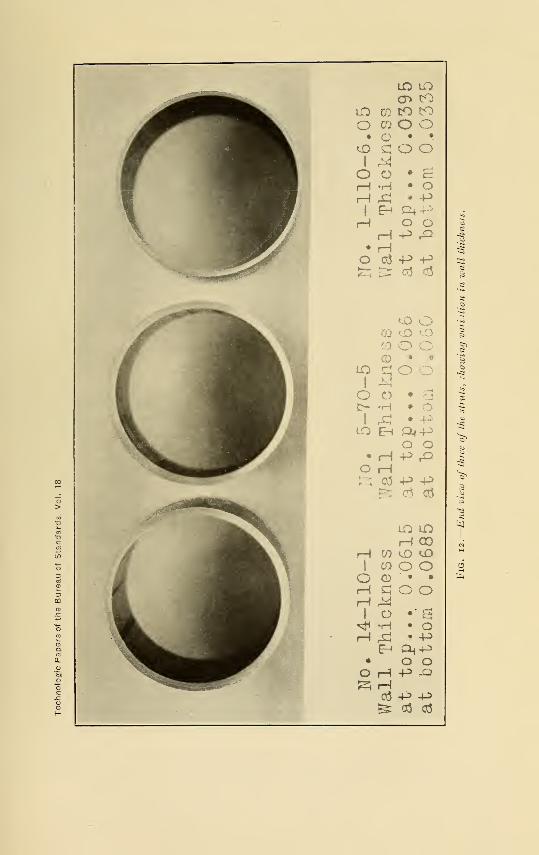
strength of struts. Figure 12 shows the variation in wall thick-
ness of three of the struts tested.
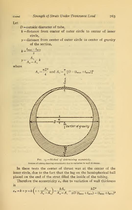
(*) DETERMINATION OF ECCENTRICITY.
1. Eccentricity Due to Variation in Wall Thickness.—Consider a cross section of the tube in which the wall thickness
varies from an average minimum thickness of tmin to an average
maximum thickness of *ma2 . (See fig. 13.)
LO lOcr> co
to m to toO CO o o
• o • •
^o qoo1 Mo o • &
rH *H • OH ^ • -P
j Eh Qlj -Pt-5H O O 3
HPrQ• H •^
O OJP-P 3£z; ^ . oj a5 ?3
•§
<£> o /i
CO kO |5
m o ^d> » • '§
1
Q
1 r—i -
o o • g-1
J> -H •<o
i ^ •
LO EH P^-P ^o o OW
• H P r^><a
o H s^.
-q CO -P -P O"
^ cd o3
"3
LO LO1
rH COr-4 CO <£> <i3
H
1 CO O O 6
O o • • £rH a O OH jy
i o ••g^t* -H • OH & • -P
E-« 0<-P• o oOH-P-QS3 rH
ct5 -p -p^ a5 o5
Greene)
Let
Strength of Struts Under Transverse Load 263
D = outside diameter of tube,
k = distance from center of outer circle to center of inner
circle,
y = distance from center of outer circle to center of gravity
of the section,
y=-^'kA Q—A 1
where
^0 =7tD 2
IT
and Ax=- [D - (tm&* + tmin)Y
4 4
Fig. 13.
—
Method of determining eccentricity.
Section of tubing showing eccentricity due to variation in wall thickness.
In these tests the center of thrust was at the center of the
inner circle, due to the fact that the lug on the hemispherical ball
placed on the end of the strut filled the inside of the tubing.
Therefore the eccentricity ew due to variation of wall thickness
is
= fc+ =kfi 1
Al \= kA ° —\ ^o~^i/ ^o~^l 2-D (tmgLX +tmin) ~ (*max + £min)
2
264 Technologic Papers of the Bureau of Standards woi.is
Should the minimum thickness be at a point other than at the
top or bottom of the tube, the eccentricity about the horizontal
axis is
ew = {k + y) sin a = A —V sin a
where a is the angle that the diameter connecting the points of
minimum and maximum wall thickness makes with the horizontal
axis. In this investigation practically all of the specimens hadthe minimum thickness either at the top or bottom when tested.
In the few cases where this condition did not exist the value of
sin a was considered as unity and the average thickness at the top
and bottom used for 2min and tmax in the formula to determine the
eccentricity about the horizontal axis.
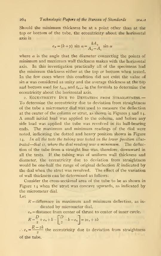
2. Eccentricity Due to Deviation from Straightness.—To determine the eccentricity due to deviation from straightness
of the tube a micrometer dial was used to measure the deflection
at the center of the column or strut, as shown in Figures 5 and 14.
A small initial load was applied to the column, and before any
side load was applied the tube was revolved in its ball-bearing
ends. The maximum and minimum readings of the dial were
noted, indicating the dotted and heavy position shown in Figure
14. In all the tests the tubing was tested in the lower position illus-
trated—that is, where the dial reading was a minimum. The deflec-
tion of the tube from a straight line was, therefore, downward in
all the tests. If the tubing was of uniform wall thickness and
diameter, the eccentricity due to deviation from straightness
would be one-half the range of original deflection R indicated bythe dial when the strut was revolved. The effect of the variation
of wall thickness can be determined as follows
:
Consider the cross-sectional area of the tube to be as shown in
Figure 14 when the strut was concave upwards, as indicated by
the micrometer dial.
Let
R = difference in maximum and minimum deflection, as in-
dicated by micrometer dial,
ex = distance from center of thrust to center of inner circle.
d . vdR =-+ex + k2 ] 2£ x + 2&
2
2
of the tube
2kthe eccentricity due to deviation from straightness
Greene] Strength of Struts Under Transverse Load 265
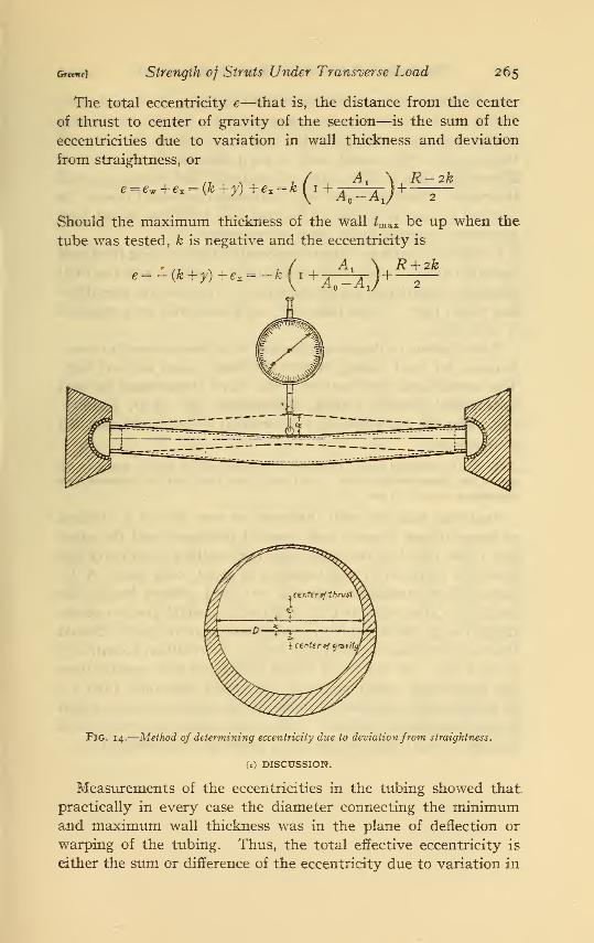
The total eccentricity e—that is, the distance from the center
of thrust to center of gravity of the section—is the sum of the
eccentricities due to variation in wall thickness and deviation
from straightness, or
,* 7 / A* \ R-2ke=ew +e* = {k+y) +ex = k I i+A _A J
+—-
—
Should the maximum thickness of the wall Zmax be up when the
tube was tested, k is negative and the eccentricity is
R + 2ke = — (k + y) + e z
(l +A^Aj+
Fig. 14.
—
Method of determining eccentricity due to deviationfrom straightness.
(c) DISCUSSION.
Measurements of the eccentricities in the tubing showed that
practically in every case the diameter connecting the minimumand maximum wall thickness was in the plane of deflection or
warping of the tubing. Thus, the total effective eccentricity is
either the sum or difference of the eccentricity due to variation in
266 Technologic Papers of the Bureau of Standards \Voi. 18
wall thickness and eccentricity due to variation in straightness.
This is to be expected, because any condition during the drawing
of the tube that would cause the wall to be thin on one side and
thick on the other would tend to warp the tube in the plane of
symmetry; that is, the plane of minimum and maximum wall
thickness. Moreover, any heat treatment that would relieve the
unequal stresses in a tube of varying wall thickness would tend
to produce warping in the plane of symmetry.
In Tables 7 and 8 are given the eccentricities resulting from wall
variation and deviation from straightness, together with the total
effective eccentricities for all the struts. The effective eccentrici-
ties varied from —0.008 inch to +0.039 inch, with an average of
+ 0.021 inch.
A comparison of these eccentricities with those allowed in speci-
fications for steel tubing shows that these values are not high.
The aeronautical specifications of the Navy Department for mild
carbon-steel seamless tubing, Specification No. 58-B, January,
1920, specifies the following for variation in wall thickness and
straightness
:
Par. 8. The variation in wall thickness of the tubes may be plus or minus 10 per
cent of the dimensions specified. In no part of any tube shall the departure from
straightness exceed i in 600.
Assuming that the wall thickness on one side of a i^-inch
16-gauge tubing is 0.065 mcn (normal thickness) and the other
side 10 per cent less, or 0.0585 inch, the resulting eccentricity due
from this variation in wall thickness is about 0.018 inch. A de-
parture from straightness of 1 in 600 for a 36-inch length, the
length of a strut with and L/r ratio of 70, would give an eccen-
tricity due to deviation from straightness of 0.060 inch. Should
these eccentricities be additive in a strut, the resultant eccentricity
is 0.078 inch. In any lot of tubing complying with specifications
the eccentricity would probably vary fairly uniformly from 0.0
to the extreme case above, so that the average eccentricity would
be approximately 0.039 inch. This value is about twice the general
average of 0.021 inch for the struts tested in this investigation.
Greene) Strength of Struts Under Transverse Load 267
TABLE 7.—Eccentricities.
1H INCHES, 20 GAUGE —=70.
Strut number.
Average wallthickness.
* l y*
Eccen-tricity
fromwall
variation.
Dialdeflec-tion.
R
Eccen-tricity
due to
crooked-ness.
Totaleccen-
Topside.
Bottomside.
tricity.
e=ew+e»
ll-70<-CInch.0.035.0365.0347.034
.033
.0325
.033
.0339
Inch.0.0335.0355.0347.0347
.037
.035
.0355
.0337
Inch.-0. 0007-.0006
.000+ .0004
+ .0020+ .0013+.0012-.0001
Inch.-0.007-.006
.000+ .0041
+ .020+ .0135+ .012-.001
Inch.-0. 0077-.0066.000
+ .0045
+ .022+ .0148+.0132-.0011
Inch.0.025.029.070.031
.033
.030
.010
.026
Inch.0.0132.015.035.015
.0145
.0137
.0035
.013
Inch.0.0055
17-70-C .00813-70-1 .0359-70-1 .019
13-70-5 .03615_70_5 .028513-70-10 .01615_70_i0 .012
Average + .0050 .0154 .0290
1J4 INCHES, 20 GAUGE— =110.
4-110-1 0.035.036.0355.035
.0393
.0345
0.036.035.036.0375
.0337
.0345
+0.0005-.0005+ .0002+ .0013
-.0028.000
+0.005-.005+ .002
+ .0125
-.0267.000
+0.0055-.0055+ .0022
+ .0138
-.0295.000
0.044.031.068.034
.050
.017
0.0215.016.034.0157
.0275
.008
0.02717-110-1 .9119-110-3 .03616-110-3 .0295
1-110-6 — .00211-104-6 .008
-.0022 .0205 .0182
\y% INCHES, 16 GAUGE -= 70.
8-70-C 0.0635.065.060.0623
.066
.064
.063
.059
0.0615.0605.065.0630
.060
.060
.063
.065
-0.001-.0022+ .0025+ .0003
-.003-.002
.000+ .003
-0. 0052-.011+ .0131
+ .0015
-.0156-.0106
.000+ .0150
-0.0062-.013+ .0156+ .0018
-.0186-.0126
.000+ .0180
0.028.054.045.052
.015
.022
.025
.023
0.015.0295.020.0255
.0105
.013
.0125
.0085
0.0095-70-C ,. .0175-70-1 .03568-70-1 .027
5-70-5 — .0085-70-5 .00048-70-20 .01257-70-20 .026
-.0019 .01«68 .0149
W2 INCHES, 16 GAUGE -=110.
3-110-1 0.0655.0615.062.063
0.0610.0685.066.060
-0. 0023+ .0036+ .002-.0015
-0.0121+ .0182+ .0105-.008
-0.0145+ .022
+ .0125-.0095
0.088.040.043.048
0.046.0166.0195.0255
0.03114-110-1 .03914-110-5 .0367-110-5 .016
+ .0026 .0269 .0305
i---Anii
R-2k
268 Technologic Papers of the Bureau of Standards
(«/) ACCURACY OF METHOD OF DETERMINING ECCENTRICITY.
[Vol. 18
From the elastic theory one may express the relation between
the lateral deflection at the middle of a column ym and the initial
eccentricity e for round end columns, as follows:
(secV^ _i
)
It can be shown that when the load P is 4/9 PE—that is, 4/9 of
Euler's maximum load—the deflection at the center of the column
is equal to the initial eccentricity, provided P does not stress the
material beyond the proportional limit. In Table 8 are given the
eccentricities and the deflection at a load of 4/9 Euler's load for
the eight columns tested. There is practically exact agreement
in all except column 9-110-C, indicating that the method of
determining the eccentricities was very accurate.
TABLE 8.—Eccentricities of Columns.
V/2 INCHES, 20 GAUGE i:«110.
Average wallthickness.
k y
Eccen-tricity
fromwallvaria-
tion.
Dial de-flection.
R
Eccen-tricity
due to
crooked-ness.
Totaleccen-tricity.
e=ew+«x
Deflec-tion of
Strut number.•
Topside.
Bottomside.
at load.
1-110-CInch.0.039.035
Inch.0.036.035
Inch.-0.0015
Inch.-0.0144
Inch.-0.0159
.00
Inch.0.104.016
Inch.0.0535.008
Inch.0.038.008
Inch.0.040
7-110-C .00 .00 .009
1
VA INCHES, 16 GAU(JE A= H0.r
10-110-C9-110-C
0.0637.060
0.064 +0.0004.064 +.0020
+ 0.002+ .010
+0.0024 0.037+.012 .100
0.018.048
0.020.060
0.019.051
iy2 INCHES, 20 GAU(JE i:=70.T
11-70-C 0.035.0365
0. 0335.0355
-0.0007 -0.007-.0006 -.006
-0.0077-.0066
0.025.029
0.0132.015
0. 0055.008
0.00417-70-C .006
iy2 INCHES, 16 GAU(IE 1=70.r
8-70-C 0.0635.065
0.0615.0605
-0.001-.0022
-0. 0052-.011
-0. 0062-.013
0.028.054
0.015.0295
0.009.017
0.0035-70-C .017
Greene) Strength of Struts Under Transverse Load 269
4. APPLICATION OF MODIFIED RATIONAL FORMULA.
The results obtained by applying the eccentricities caused by
tube irregularities to the modified rational formula
. P Pec wt° =A +-T seC
2
[P wEc/ T [P \
are given in Table 9. The maximum compressive stress /c to
cause failure of the struts subjected to combined column and
transverse loading are in very close agreement with the yield
point of the material. The small discrepancies that exist are on
the side of safety. In the next to last column in the table are
given the ultimate compressive stress SCy approximately the yield
point in compression for the material, determined from the com-
pression test of short specimen (see Table 2) . The maximumcompressive stress at failure fc for the struts are in extremely close
agreement with these values. The general average of the maxi-
mum compressive stress at failure for the struts is 70,600 lbs. /in.2
and the average ultimate compressive stress for short column, or
approximate yield point in compression for the material, is 69,700,
an error of about 1 per cent, which is remarkably close for experi-
mental data involving so many variables.
TABLE 9.—Results Obtained by Use of Modified Rational Formula for CombinedLoading.
iy2 INCHES, 20 GAUGE -=70.
Strut number.Trans-verseload.
Maxi-mum
bendingstress. 1
5B
Com-pressivestress
PA
Maxi-mum
compres-sive
stress at
failure. 2
h
Yieldpoint of
material(tension).
Ratio.
/o
YP
Ultimatecompres-
sivestress(short
column).S
Ratio.
USo
13-70-1Pounds.
1.251.255.05.010.010.0
Lbs. /in. 2
26, 55026, 80037, 70038,00050, 70049, 700
Lbs./in.2
41,20044,40030,10030, 90022,90022,500
Lbs./in.2
67, 75071, 20067,80068, 90073,60072, 200
Lbs./in.2
68, 90066, 80068, 90069,90068,90069, 900
Per cent.981069899107103
Lbs./in.2
69,30066,40069, 30068,80069,30068,800
Per cent.98
9-70-1 10713-70-5 9815-70-5 10013-70-10 10615-70-10 105
Average 70, 200 69,000 102 68,600 102
1H INCHES, 20 GAUGE —=110.
4-110-1 1.01.03.03.06.056.05
50, 10049,60057,50052,56061,09063,600
19,40019,90014,30013, 5508,200
10, 300
69, 50069, 50071, 80066,11069, 30073, 900
63, 40067, 40066,80062, 200
61, 20069,000
109103107106113107
65, 20068, 40066,40066, 20064,70067,500
10617-110-1 1019-110-3 108
10016-110-31-110-6 10711-110-6 109
Average 70,000 65,000 107 66, 400 105
See footnotes on p. 270.
270 Technologic Papers of the Bureau of Standards \y i. 18
TABLE 9.—Results Obtained by Use of Modified Rational Formula for CombinedLoading—Continued
.
1H INCHES, 16 GAUGE -= 70.
Strut number.Trans-verseload.
Maxi-mum
bendingstress, i
5B
Com-pressivestress.
PA
Maxi-mum
compres-sive
stress at
failure.?
/c
Yieldpoint of
material(tension).
Ratio.
hYP
Ultimatecompres-
sivestress(short
column).So
Ratio.
So
5-70-1Pounds.
1.01.05.05.020.020.0
Lbs./in.2
27,04027, 70025, 96025, 78056, 00054, 240
Lbs./in.2
42, 90045, 50042, 50039,30023, 25019, 780
Lbs./in.2
69, 94073,20068, 46065, 08079, 25074,000
Lbs. /in.*
70, 00070, 20070, 00067,50070,20067, 500
Per cent.
1001049896113109
Lbs./in.J
71,60074,80071,60069, 30074, 80069, 300
Per cent.
988-70-1 985-70-5 967-70-5 948-70-20 1067-70-20 107
Average 71,650 69,200 103 71,900 100
\y2 INCHES, 16 GAUGE -=110.
3-110-1 1.01.05.05.0
60,20044,77054, 74053, 810
21, 100
19, 87014, 05014, 250
81,30064,70068,80068, 060
71,30064,60064,60067, 500
114100106100
80, 40068, 80068,800£9,300
10114-110-1 9414-110-5 1007-110-5 98
Average 70, 700 67,000 105 71, 800 98
„ Mo Pec tv f~P , wEc / it I P \Sb=—=— sec 7 -y/p-^-p- \
sec t -\pir x
)
Mo
The accuracy and safety with which this modified rational
formula determines the stress and strength of struts subjected to
transverse loading is graphically shown in the right half of Figure
io. In this figure the same values for abscissas are used as in
the left half of the figure. The ordinate values fc , the maximumcompressive stresses at failure, were computed by the modified
formula. It will be seen that the small variations which exist are
less than the variations in the short compression tests. The two
high values are for tubing Nos. 3 and 8, which had a high yield
point in compression.
The relation between the maximum compressive stress at
failure determined by the formula and the yield point of the
material is shown in Figure 15. The numbers assigned to the
different sections of tubing used in these tests are plotted as
abscissas and the maximum compressive stress at failure for the
struts cut from these sections as ordinates. The heavy line con-
nects the value of ultimate or maximum compressive stress,
approximate yield point in compression obtained from short
Greene] Strength of Struts Under Transverse Load 271
compression tests of each section of tubing. This figure also
shows the variation in per cent of maximum compressive stress
from the yield point of the material. It will be noted that the
failing stress of struts computed by the formula agrees very closely
with the failing stress of the short compression pieces.
Theoretically, the modified formula is not exact above the pro-
portional limit, as the formula involves the modulus of elasticity
E. In this investigation the material used had very nearly the
same proportional limit and yield point values. The assumption
of strict proportionality between stress and strain up to failure,
although not theoretically exact, gives results that agree within a
very small percentage error with actual conditions, and for all
practical purposes can be used in design.
60000
70000
60000
£ S00QO
1 44000
£ 30000
r 10000
>
ss>
! s.>*
1
Ull im a
1
te >orr pre *»>isV
to a It.?
I b c 1 >- Jl \I ^jjul£Timi res SJ0J.iJ^s
HOX< 1
C 1 < 1>
\ k33 . >
<i
\ 1
c
Pe6
ltd 1? J 1
am 'Sff/i 9f Fa 1 (in Q$rrr \\ n Kf'p d ffin t -/0%/-"
lot IPdof
nst n
Yie 4 ,°onir 1
W'i t
n Cam fA siion
Alax murn < 'on pri'.55 ve St, ess at Fai bn
fc- £ i km£ t P ?c MCffi I* "j tt UCmh )
4 ft r
$tru! 5 H ith in AS er ;e I.oa dm 91
16
Section No. of Tubinq13 11 5 II 15
7If 3 f I
esuqe A/o.
20 20 lb 20 20 a "20 20 20
16
20
Fig. 15. Comparison of the maximum compressive stress at failure by modified rational
formula with the yield point of the material.
5. APPLICATION OF "SECANT" COLUMN FORMULA.
(a) TO COLUMNS.
The modified rational formula may be readily applied to col-
umns to determine the maximum compressive stress to cause
failure. By this formula the maximum intensity of compressive
stress is
, P Pec UP wEc(l\p\^)
272 Technologic Papers of the Bureau of Standards [vu. 18
For columns the transverse load w is zero, so that the above
formula becomes
I P PeC 7T
^=A + -r sec2
or
'-Uec L
1+ -2 sec -r2
2
which is the well-known "secant" formula for columns with
eccentric loading.
The results of the column tests are given in Table 10. Theeccentricities about the horizontal axis have been used to deter-
mine the maximum compressive stress for the shorter columns.
The long columns with an Ljr ratio of no failed at Euler's maxi-
mum load. The results indicate that there is fairly close agree-
ment between the maximum compressive stress at failure computed
by the " secant" column formula and the yield point of the mate-
rial with the exception of column 5-70- C. This column failed bydeflecting sideways, indicating that the eccentricity was greater
than the value taken about the horizontal axis.
TABLE 10.—Results of Column Tests.
m INCHES, 20 GAUGE.
Strut number.L
r
ratio.
Columnunit
stress.
PA
Euler
P 7r2£
7rW-
Eccen-tricity e
abouthori-zontalaxis.
Maxi-mumcom-
pressivestress. 1
/«
Ultimatecom-
pressivestress 5.(short
column).
11-70-C 7070
110110
Lbs./in.a
52,90051, 93023,20024,000
Lbs./in.*
58, 500
58,40023,60023,700
Inch.0.0055.008
Lbs./in.<>
71, 40072,400
Lbs./in.*
67,60017-70-C 68,4001-110-C7-110-C
1V2 INCHES, 16 GAUGE.
8-70-C 7070110110
52, 80047, 65023,50022,500
58,10058, 300
23, 50023,500
0.009.0017
72,30063,600
74,8005-70-C 71,60010-110-C9-110-C
(I+
r^SeC lVfc)'
( b ) TO STRUTS WITH TRANSVERSE LOADING.
The "secant" column formula can be applied to struts sub-
jected to transverse loading with safety and a reasonable degree
of accuracy if certain modifications in the determination of the
effective eccentricity are made. Consider, first, a strut to be
Greene) Strength of Struts Under Transverse Load 273
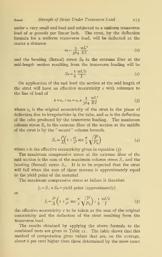
under a very small end load and subjected to a uniform transverse
load of w pounds per linear inch. The strut, by the deflection
formula for a uniform transverse load, will be deflected at the
center a distance
384 EI }
and the bending (flexual) stress Sb in the extreme fiber at the
mid-length section resulting from the transverse loading will be
c 1 wUcSb =s~T (2)
On application of the end load the section at the mid length of
the strut will have an effective eccentricity e with reference to
the line of load of
e = e°+ e* = e
°+^E7 (3)
where e is the original eccentricity of the strut in the plane of
deflection due to irregularities in the tube, and e# is the deflection
of the tube produced by the transverse loading. The maximumcolumn stress Su in the extreme fiber of the section at the middle
of the strut is by the " secant" column formula
S.-^i+Jsec^g) (4)
where e is the effective eccentricity given in equation (3)
.
The maximum compressive stress at the extreme fiber of the
mid section is the sum of the maximum column stress 5 U and the
bending (flexual) stress SB . It is to be expected that the strut
will fail when the sum of these stresses is approximately equal
to the yield point of the material.
The maximum compressive stress at failure is therefore
}c=S u +Sb = yield point (approximately)
or
tA{ec wJ+^^^fel'Q -7- (5)
the effective eccentricity e to be taken as the sum of the original
eccentricity and the deflection of the strut resulting from the
transverse load.
The results obtained by applying the above formula to the
combined tests are given in Table 1 1 . The table shows that this
method of computation gives values that are, on the average,
about 6 per cent higher than those determined by the more exact
274 Technologic Papers of the Bureau of Standards [Voi.18
formula. The error, however, is on the side of safety. Whereextreme accuracy is not required, this formula can be safely used
and is more reliable for designing than Perry's formula, whichneglects the effect of eccentricities.
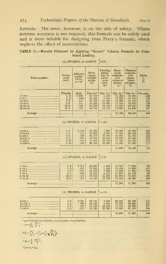
TABLE 11.—Results Obtained by Applying "Secant" Column Formula for Com-bined Loading.
\y2 INCHES, 20 GAUGE -=70.
Bending Maxi- Ultimate
Trans-Effectiveeccen-tricity.
Maxi-mum
stressdue to
mumcompres-
compres-sive Ratio.
Strut number. verse column trans- sive stress /oload. stress. verse stress at (short SoW load. failure. column).
Sb S /.< S„
Pounds. Inch. Lbs./in.2 Lbs. in. 2 Lbs./in.2 Lbs./in.* Per cent.13-70-1 1.25 0.058 67, 700 3,600 71, 300 69, 300 1039 70-1 . . 1.25 .0405 69, 300 3,600 72, 900
70, 00071,100
66, 40069 300
11013_70_5 5.0 .126 55, 400 14, 600 10115-70-5 5.0 .121 56, 200 14, 900 68, 800 10313_70_10 10.0 .198 46, 100 29,400
29, 20075, 500 69, 300
68, 800109
15-70-10 10.0 .199 44,700 73, 900 107
72,400 68,600 105
\y2 INCHES, 20 GAUGE — -110.
4-110-1 1.01.03.03.06.056.05
0.135.119.358.347.644.542
69, 40070, 80056, 200
49, 50031,90038, 200
7,0006,900
20, 70020, 80039, 500
38, 000
76, 40077, 70076, 90070, 30071,40076, 200
65, 200
68, 40066, 400
66, 200
64, 70067, 600
11717-110-1 1139-110-3 11616-110-3 1061 HO-6 11011 104-6- - 113
74, 800 66, 400 112I r
1H INCHES, 16 GAUGE
5 70-1 . . 1.01.05.05.020.020.0
0.045.037.042.050.212.225
68, 90073, 80065, 00059, 65049, 40041,400
1,6601,6307,9008,13032,50033, 700
70, 56075, 40072, 90067, 80081,90075, 100
71,60074, 80071,60069, 30074, 80069, 300
988 70-1 1015_70_5 . . 1027-70-5 . . 988-70-20 1097_70_20 108
72, 300 71,900 102
\y2 INCHES, 16 GAUGE - = 110.
3-110-1. . . 1.01.05.05.0
0.091.099.337.327
85, 700
66, 20054, 100
53, 300
3,9004,000
20, 10020, 300
89, 60070, 200
74, 10073, 600
80, 40068, 80068, 80069, 300
111
14-110-1 10214-110-5 1077-110-5 106
76, 800 71,800 106
e = original eccentricity due to tube irregularities.
=_5_ WL*384 E I
Su-K i+^secfV£)'1 wL*c
s Sb=
'/c=5u+5b.
Greene) Strength of Struts Under Transverse Load 275
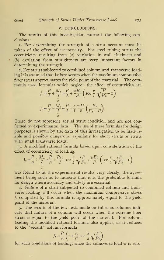
V. CONCLUSIONS.
The results of this investigation warrant the following con-
clusions :
1. For determining the strength of a strut account must be
taken of the effect of eccentricity. For steel tubing struts the
eccentricity resulting from (a) variation in wall thickness and
.(b) deviation from straightness are very important factors in
determining the strength.
2. For struts subjected to combined column and transverse load-
ing it is assumed that failure occurs when the maximum compressive
fiber stress approximates the yield point of the material. The com-monly used formulas which neglect the effect of eccentricity are
P M P wEc ( ir l~P \
c
h A +I A + /8 \Pv-P/c
These do not represent actual strut condition and are not con-
firmed by experimental data. The use of these formulas for design
purposes is shown by the data of this investigation to be inadvis-
able and possibly dangerous, especially for short struts or struts
with small transverse loads.
3. A modified rational formula based upon consideration of the
effect of eccentricity of loading,
, P M P Pec it IP wEc / t [P \/c = A + T~
=A +^ seC
2 V^ + "^VSeC 2VPE"Vc
was found to fit the experimental results very closely, the agree-
ment being such as to indicate that it is the preferable formula
for design where accuracy and safety are essential.
4. Failure of a strut subjected to combined column and trans-
verse loading will occur when the maximum compressive stress
/c computed by this formula is approximately equal to the yield
point of the material.
5. The results of the few tests made on tubes as columns indi-
cate that failure of a column will occur when the extreme fiber
stress is equal to the yield point of the material. For columnloading the modified rational formula also applies, as it reduces
to the "secant" column formula
. P ( ec it l~P\/c=z ^i+
r,sec-yF-J
for such conditions of loading, since the transverse load w is zero.
276 Technologic Papers of the Bureau of Standards \V0i.18
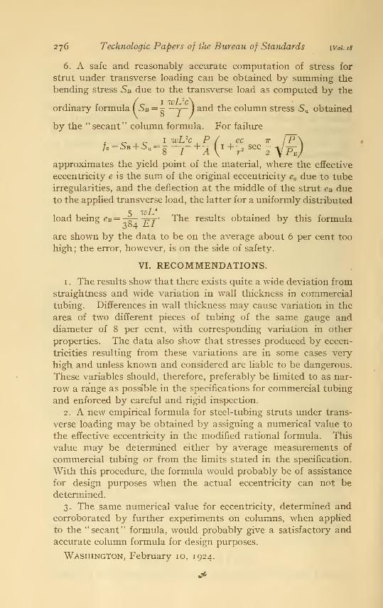
6. A safe and reasonably accurate computation of stress for
strut under transverse loading can be obtained by summing the
bending stress 5b due to the transverse load as computed by the
(1 ivTJ*c\Sb = ~ —j— ) and the column stress 5U obtained
by the "secant" column formula. For failure
1 wUc P ( ec tt
/c =SB + 5u = g—r + -
?(^i+-
2 sec-
approximates the yield point of the material, where the effective
eccentricity e is the sum of the original eccentricity ec due to tube
irregularities, and the deflection at the middle of the strut eB dueto the applied transverse load, the latter for a uniformly distributed
load being eB = -^- -^y The results obtained by this formula
are shown by the data to be on the average about 6 per cent too
high ; the error, however, is on the side of safety.
VI. RECOMMENDATIONS.
1
.
The results show that there exists quite a wide deviation from
straightness and wide variation in wall thickness in commercial
tubing. Differences in wall thickness may cause variation in the
area of two different pieces of tubing of the same gauge and
diameter of 8 per cent, with corresponding variation in other
properties. The data also show that stresses produced by eccen-
tricities resulting from these variations are in some cases very
high and unless known and considered are liable to be dangerous.
These variables should, therefore, preferably be limited to as nar-
row a range as possible in the specifications for commercial tubing
and enforced by careful and rigid inspection.
2. A new empirical formula for steel-tubing struts under trans-
verse loading may be obtained by assigning a numerical value to
the effective eccentricity in the modified rational formula. This
value may be determined either by average measurements of
commercial tubing or from the limits stated in the specification.
With this procedure, the formula would probably be of assistance
for design purposes when the actual eccentricity can not be
determined.
3. The same numerical value for eccentricity, determined andcorroborated by further experiments on columns, when applied
to the " secant" formula, would probably give a satisfactory andaccurate column formula for design purposes.
Washington, February 10, 1924.