Embed Size (px)
Citation preview
Strauss Wind Energy Project TAB G: Project Description
March 15, 2018 Sapphos Environmental, Inc.
Page G-I
STRAUSS WIND ENERGY PROJECT
CONDITIONAL USE APPLICATION
TAB G: PROJECT DESCRIPTION
This project description for the Strauss Wind Energy Project (Project) includes its location and
setting, components, construction, and operational practices; quality assurance (QA), quality
control (QC), and environmental and health and safety compliance practices; and environmental
protection measures. Also included is a discussion of local, state, and federal permits and
approvals that could be required prior to implementation of the Project.
Strauss Wind Energy Project TAB G: Project Description
March 15, 2018 Sapphos Environmental, Inc.
Page G-II
TABLE OF CONTENTS
SECTIONS PAGE
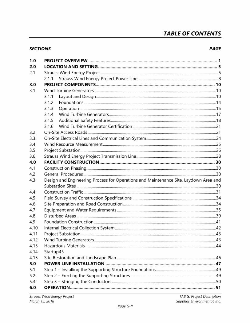
1.0 PROJECT OVERVIEW ......................................................................................................... 1
2.0 LOCATION AND SETTING ................................................................................................. 5
2.1 Strauss Wind Energy Project ........................................................................................................................ 5
2.1.1 Strauss Wind Energy Project Power Line ................................................................................. 8
3.0 PROJECT COMPONENTS................................................................................................. 10
3.1 Wind Turbine Generators ............................................................................................................................ 10
3.1.1 Layout and Design .......................................................................................................................... 10
3.1.2 Foundations ...................................................................................................................................... 14
3.1.3 Operation ........................................................................................................................................... 15
3.1.4 Wind Turbine Generators ............................................................................................................. 17
3.1.5 Additional Safety Features ........................................................................................................... 18
3.1.6 Wind Turbine Generator Certification ..................................................................................... 21
3.2 On-Site Access Roads ................................................................................................................................... 21
3.3 On-Site Electrical Lines and Communication System ....................................................................... 24
3.4 Wind Resource Measurement ................................................................................................................... 25
3.5 Project Substation .......................................................................................................................................... 26
3.6 Strauss Wind Energy Project Transmission Line ................................................................................. 28
4.0 FACILITY CONSTRUCTION .............................................................................................. 30
4.1 Construction Phasing .................................................................................................................................... 30
4.2 General Procedures ....................................................................................................................................... 30
4.3 Design and Engineering Process for Operations and Maintenance Site, Laydown Area and
Substation Sites .............................................................................................................................................. 30
4.4 Construction Traffic ....................................................................................................................................... 31
4.5 Field Survey and Construction Specifications ..................................................................................... 34
4.6 Site Preparation and Road Construction ............................................................................................... 34
4.7 Equipment and Water Requirements ..................................................................................................... 35
4.8 Disturbed Areas .............................................................................................................................................. 39
4.9 Foundation Construction ............................................................................................................................ 41
4.10 Internal Electrical Collection System ....................................................................................................... 42
4.11 Project Substation .......................................................................................................................................... 43
4.12 Wind Turbine Generators ............................................................................................................................ 43
4.13 Hazardous Materials ..................................................................................................................................... 44
4.14 Startup 45
4.15 Site Restoration and Landscape Plan ..................................................................................................... 46
5.0 POWER LINE INSTALLATION ......................................................................................... 47
5.1 Step 1 – Installing the Supporting Structure Foundations ............................................................. 49
5.2 Step 2 – Erecting the Supporting Structures ....................................................................................... 49
5.3 Step 3 – Stringing the Conductors .......................................................................................................... 50
6.0 OPERATION ...................................................................................................................... 51
Strauss Wind Energy Project TAB G: Project Description
March 15, 2018 Sapphos Environmental, Inc.
Page G-III
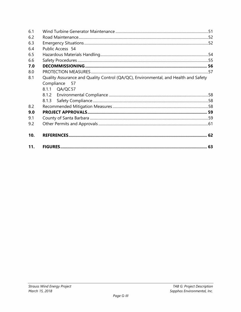
6.1 Wind Turbine Generator Maintenance .................................................................................................. 51
6.2 Road Maintenance ......................................................................................................................................... 52
6.3 Emergency Situations ................................................................................................................................... 52
6.4 Public Access 54
6.5 Hazardous Materials Handling .................................................................................................................. 54
6.6 Safety Procedures .......................................................................................................................................... 55
7.0 DECOMMISSIONING ....................................................................................................... 56
8.0 PROTECTION MEASURES ............................................................................................................................ 57
8.1 Quality Assurance and Quality Control (QA/QC), Environmental, and Health and Safety
Compliance 57
8.1.1 QA/QC 57
8.1.2 Environmental Compliance ......................................................................................................... 58
8.1.3 Safety Compliance .......................................................................................................................... 58
8.2 Recommended Mitigation Measures ..................................................................................................... 58
9.0 PROJECT APPROVALS ..................................................................................................... 59
9.1 County of Santa Barbara ............................................................................................................................. 59
9.2 Other Permits and Approvals .................................................................................................................... 61
10. REFERENCES ..................................................................................................................... 62
11. FIGURES ............................................................................................................................ 63
Strauss Wind Energy Project TAB G: Project Description
March 15, 2018 Sapphos Environmental, Inc.
Page G-1
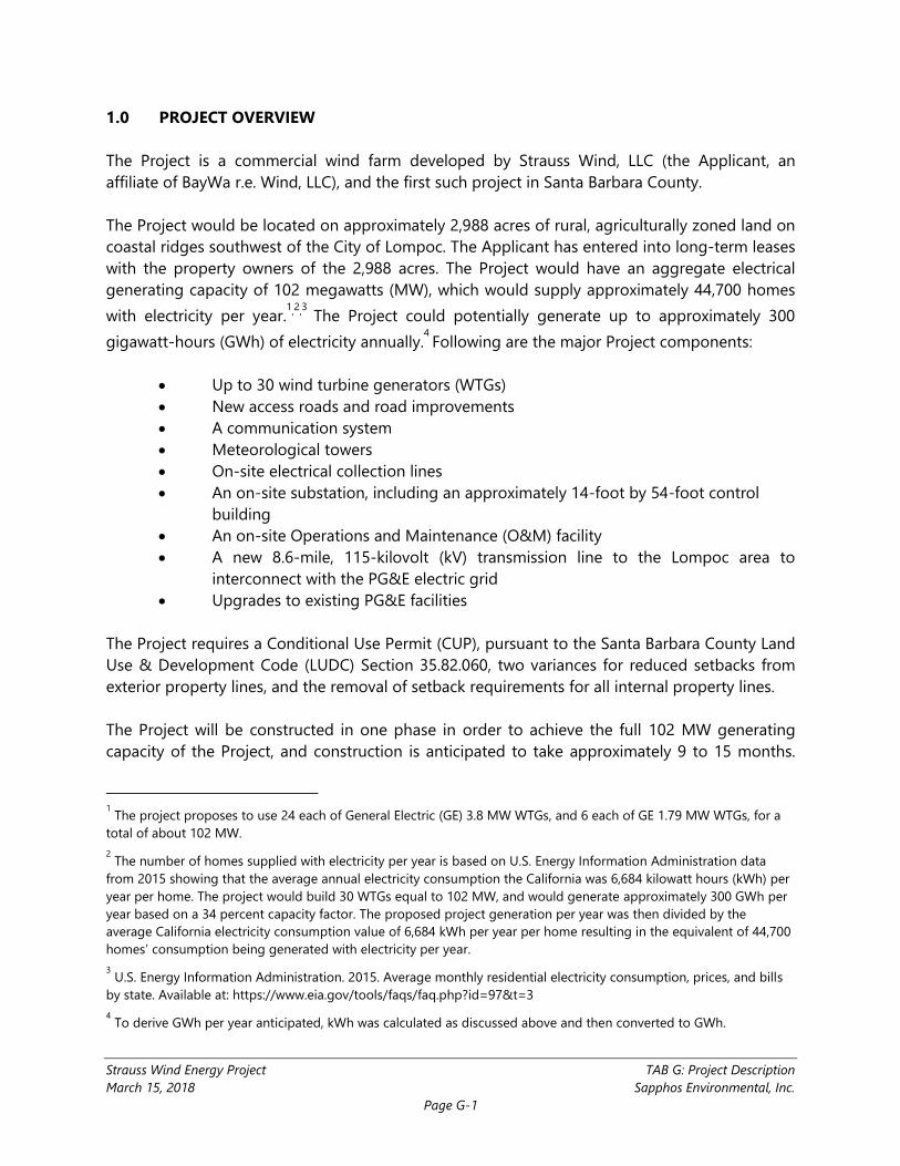
1.0 PROJECT OVERVIEW
The Project is a commercial wind farm developed by Strauss Wind, LLC (the Applicant, an
affiliate of BayWa r.e. Wind, LLC), and the first such project in Santa Barbara County.
The Project would be located on approximately 2,988 acres of rural, agriculturally zoned land on
coastal ridges southwest of the City of Lompoc. The Applicant has entered into long-term leases
with the property owners of the 2,988 acres. The Project would have an aggregate electrical
generating capacity of 102 megawatts (MW), which would supply approximately 44,700 homes
with electricity per year.1,2,3 The Project could potentially generate up to approximately 300
gigawatt-hours (GWh) of electricity annually.4 Following are the major Project components:
Up to 30 wind turbine generators (WTGs)
New access roads and road improvements
A communication system
Meteorological towers
On-site electrical collection lines
An on-site substation, including an approximately 14-foot by 54-foot control
building
An on-site Operations and Maintenance (O&M) facility
A new 8.6-mile, 115-kilovolt (kV) transmission line to the Lompoc area to
interconnect with the PG&E electric grid
Upgrades to existing PG&E facilities
The Project requires a Conditional Use Permit (CUP), pursuant to the Santa Barbara County Land
Use & Development Code (LUDC) Section 35.82.060, two variances for reduced setbacks from
exterior property lines, and the removal of setback requirements for all internal property lines.
The Project will be constructed in one phase in order to achieve the full 102 MW generating
capacity of the Project, and construction is anticipated to take approximately 9 to 15 months.
1 The project proposes to use 24 each of General Electric (GE) 3.8 MW WTGs, and 6 each of GE 1.79 MW WTGs, for a
total of about 102 MW.
2 The number of homes supplied with electricity per year is based on U.S. Energy Information Administration data
from 2015 showing that the average annual electricity consumption the California was 6,684 kilowatt hours (kWh) per
year per home. The project would build 30 WTGs equal to 102 MW, and would generate approximately 300 GWh per
year based on a 34 percent capacity factor. The proposed project generation per year was then divided by the
average California electricity consumption value of 6,684 kWh per year per home resulting in the equivalent of 44,700
homes’ consumption being generated with electricity per year.
3 U.S. Energy Information Administration. 2015. Average monthly residential electricity consumption, prices, and bills
by state. Available at: https://www.eia.gov/tools/faqs/faq.php?id=97&t=3
4 To derive GWh per year anticipated, kWh was calculated as discussed above and then converted to GWh.

Strauss Wind Energy Project TAB G: Project Description
March 15, 2018 Sapphos Environmental, Inc.
Page G-2
The analysis presented herein assumes an approximate 10-month construction period. The
Project is expected to have an operational life of approximately 30 years. Future scenarios could
include lease renewals and possible repowering of the wind farm with advanced WTGs or
decommissioning the Project and restoring the land.
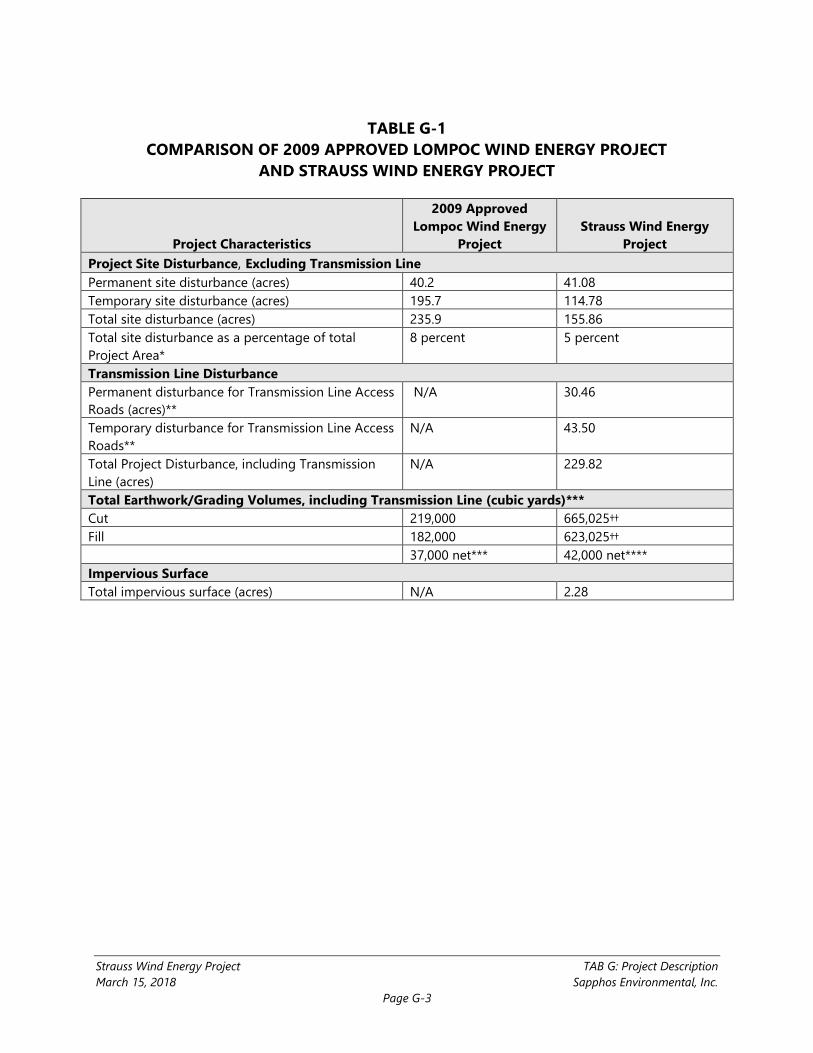
The Applicant has designed the Project to use more efficient WTGs, thus allowing cut and fill to
be balanced on site (Table G-1, Comparison of 2009 Approved Lompoc Wind Energy Project and
Strauss Wind Energy Project). The proposed revised grading plan and WTGs reduces the net area
of grading from 235.9 acres in the Lompoc Wind Energy Project (LWEP), approved by the County
for this property in 2009, to 155.86 acres for the Project Area and a total of 73.96 acres for the
transmission corridor which was not analyzed or included in the 2009 version of the LWEP. The
net area of grading including the transmission line access roads is 229.82 acres and shown in
(Table G-1).5 The area of land disturbance has been calculated based on the Preliminary
Grading Plan (in the Maps tab), using GIS analysis. The evaluation of temporary and permanent
impacts includes turbine pads, access roads, internal collection, substation, staging area, O&M
facility, external transmission line, and access roads to the pole locations of the external
transmission line. In addition, a 10-foot buffer has been added to the preliminary grading
disturbance area to account for a potential disturbance outside of the grading design. It is not
anticipated that any disturbance would occur outside of this additional 10-foot buffer area.
The total area of permanent and temporary impacts includes some existing developed areas,
such as dirt ranch roads. Table G-1 shows existing dirt roads that will be improved for access to
WTGs and transmission line construction. Wherever possible, proposed roads were aligned with
existing roads and areas of disturbance within the Project area. However, in some areas, new
roads were required to be constructed to gain access to the best available wind resources.
Similarly, some of the existing roads could not be utilized due to excessive grades or insufficient
turning radii to accommodate the transport of turbine components and construction
equipment. All grading and temporary and permanent removal of vegetation have been
calculated within the assessment of temporary and permanent impacts, inclusive of the 10-foot
buffer area.
5 County of Santa Barbara Planning and Development Department, Energy Division. August 2008. Certified 10
February 2009. Final Environmental Impact Report: Lompoc Wind Energy Project. County EIR No. 06EIR-00000-00004.
State Clearinghouse No. 2006071008. Prepared by Aspen Environmental Group, Agoura Hills, CA.
Strauss Wind Energy Project TAB G: Project Description
March 15, 2018 Sapphos Environmental, Inc.
Page G-3
TABLE G-1
COMPARISON OF 2009 APPROVED LOMPOC WIND ENERGY PROJECT
AND STRAUSS WIND ENERGY PROJECT
Project Characteristics
2009 Approved
Lompoc Wind Energy
Project
Strauss Wind Energy
Project
Project Site Disturbance, Excluding Transmission Line
Permanent site disturbance (acres) 40.2 41.08
Temporary site disturbance (acres) 195.7 114.78
Total site disturbance (acres) 235.9 155.86
Total site disturbance as a percentage of total
Project Area*
8 percent 5 percent
Transmission Line Disturbance
Permanent disturbance for Transmission Line Access
Roads (acres)**
N/A 30.46
Temporary disturbance for Transmission Line Access
Roads**
N/A 43.50
Total Project Disturbance, including Transmission
Line (acres)
N/A 229.82
Total Earthwork/Grading Volumes, including Transmission Line (cubic yards)***
Cut 219,000 665,025††
Fill 182,000 623,025††
37,000 net*** 42,000 net****
Impervious Surface
Total impervious surface (acres) N/A 2.28

Strauss Wind Energy Project TAB G: Project Description
March 15, 2018 Sapphos Environmental, Inc.
Page G-4
TABLE G-1
COMPARISON OF 2009 APPROVED LOMPOC WIND ENERGY PROJECT
AND STRAUSS WIND ENERGY PROJECT
Project Characteristics
2009 Approved
Lompoc Wind Energy
Project
Strauss Wind Energy
Project
Road Improvements, including Transmission Line
Improvements to existing roads to access turbines
(miles)
N/A 2.6†
New roads to access turbines (miles) 5.5 9.9
Improvements to existing roads for transmission
line construction (miles)
N/A 13.5
New roads for transmission line construction (miles) N/A 4.4
Wind Turbine Generators (WTGs)
Total number of proposed WTGs 651 30
WTG details 1.5 MW WTG Model 11 GE 1.79 MW WTG Model
and GE 3.8 MW WTG
Model
Number of WTGs by model 65 ea. 1.5 MW1 6 ea. GE 1.79 MW, 24 ea.
GE 3.8 MW
Total height of WTG 389 or 397 feet (119 or
121 meters) from
foundation to blade
tip2
GE 3.8 MW WTG: 492 feet
(150 meters) from
foundation to blade tip.
GE 1.79 MW WTG: 427 feet
(130 meters) from
foundation to blade tip,
Construction Truck Trips
Total Truck Trips 12,270***** 16,189******
NOTES:
* Total Project Area = 2,988 acres excluding transmission line which was not calculated for the previous LWEP.
**Permanent and temporary disturbance calculations for the transmission line access roads include both
improvements to existing roads and construction of new roads.
*** LWEP total cut and fill volumes were estimated for roadwork only (401,000 cubic yards [cy]). As a result, actual
volumes were likely much greater when considering all Project components.
**** Earthwork for the Project is expected to be balanced on site as a result of shrinkage and settling.
***** Based on a 6-month construction schedule.
****** Based on a 10-month construction schedule.
† Includes improvement of non-County, onsite ranch roads only.
†† Includes existing and new roads for transmission line construction. 1 Section 3.2, Aesthetics/Visual Resources Impacts, of the 2009 FEIR developed the visual simulations for the WTGs
using an 80 unit worst-case scenario as the basis for the analysis because the precise locations of the WTGs were not
known at the time of the aesthetics evaluation. 2 Section 3.2, Aesthetics/Visual Resources Impacts, of the 2009 FEIR assumed a worst-case scenario total WTG height of
397 feet for visual impact analysis purposes, except for Figure 3.2.18B, which was prepared assuming that six of the
WTGs would be 436 feet in height and the other four WTGs would be 389 feet.
SOURCE: County of Santa Barbara Planning and Development Department, Energy Division. August 2008. Certified 10
February 2009. Final Environmental Impact Report: Lompoc Wind Energy Project. County EIR No. 06EIR-00000-00004.
Strauss Wind Energy Project TAB G: Project Description
March 15, 2018 Sapphos Environmental, Inc.
Page G-5
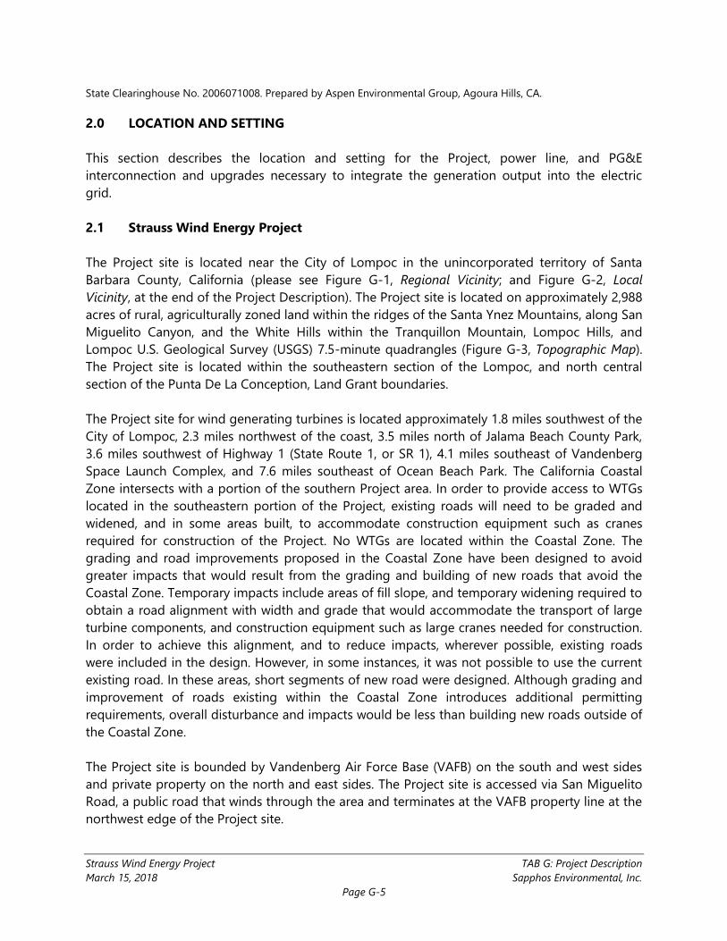
State Clearinghouse No. 2006071008. Prepared by Aspen Environmental Group, Agoura Hills, CA.
2.0 LOCATION AND SETTING
This section describes the location and setting for the Project, power line, and PG&E
interconnection and upgrades necessary to integrate the generation output into the electric
grid.
2.1 Strauss Wind Energy Project
The Project site is located near the City of Lompoc in the unincorporated territory of Santa
Barbara County, California (please see Figure G-1, Regional Vicinity; and Figure G-2, Local
Vicinity, at the end of the Project Description). The Project site is located on approximately 2,988
acres of rural, agriculturally zoned land within the ridges of the Santa Ynez Mountains, along San
Miguelito Canyon, and the White Hills within the Tranquillon Mountain, Lompoc Hills, and
Lompoc U.S. Geological Survey (USGS) 7.5-minute quadrangles (Figure G-3, Topographic Map).
The Project site is located within the southeastern section of the Lompoc, and north central
section of the Punta De La Conception, Land Grant boundaries.
The Project site for wind generating turbines is located approximately 1.8 miles southwest of the
City of Lompoc, 2.3 miles northwest of the coast, 3.5 miles north of Jalama Beach County Park,
3.6 miles southwest of Highway 1 (State Route 1, or SR 1), 4.1 miles southeast of Vandenberg
Space Launch Complex, and 7.6 miles southeast of Ocean Beach Park. The California Coastal
Zone intersects with a portion of the southern Project area. In order to provide access to WTGs
located in the southeastern portion of the Project, existing roads will need to be graded and
widened, and in some areas built, to accommodate construction equipment such as cranes
required for construction of the Project. No WTGs are located within the Coastal Zone. The
grading and road improvements proposed in the Coastal Zone have been designed to avoid
greater impacts that would result from the grading and building of new roads that avoid the
Coastal Zone. Temporary impacts include areas of fill slope, and temporary widening required to
obtain a road alignment with width and grade that would accommodate the transport of large
turbine components, and construction equipment such as large cranes needed for construction.
In order to achieve this alignment, and to reduce impacts, wherever possible, existing roads
were included in the design. However, in some instances, it was not possible to use the current
existing road. In these areas, short segments of new road were designed. Although grading and
improvement of roads existing within the Coastal Zone introduces additional permitting
requirements, overall disturbance and impacts would be less than building new roads outside of
the Coastal Zone.
The Project site is bounded by Vandenberg Air Force Base (VAFB) on the south and west sides
and private property on the north and east sides. The Project site is accessed via San Miguelito
Road, a public road that winds through the area and terminates at the VAFB property line at the
northwest edge of the Project site.

Strauss Wind Energy Project TAB G: Project Description
March 15, 2018 Sapphos Environmental, Inc.
Page G-6
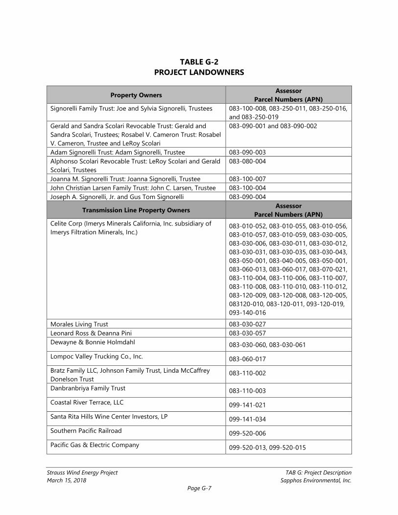
The Project site comprises 11 privately owned parcels covering approximately 2,988 acres (4.6
square miles—see Site Plan in the Maps tab). There are two small parcels owned by the federal
government that are located within the Project area: APN: 083-100-006, 0.05 acres; and APN:
083-250-009, 0.61 acres). These parcels are not part of the Project, and no development would
occur within or near these parcels. The landowners and assessor parcel numbers for properties
are shown in Table G-2 (Project Landowners). The properties are zoned for agriculture (AG-100),
and all are under Williamson Act agricultural preserve contracts. Historically, some rock
quarrying occurred in the area. The principal use of the land is cattle grazing. Single-family
residences or mobile homes and agricultural accessory structures are located on seven of the 11
parcels. The adjacent private properties are also agriculturally zoned.
Strauss Wind Energy Project TAB G: Project Description
March 15, 2018 Sapphos Environmental, Inc.
Page G-7
TABLE G-2
PROJECT LANDOWNERS
Property Owners Assessor
Parcel Numbers (APN)
Signorelli Family Trust: Joe and Sylvia Signorelli, Trustees 083-100-008, 083-250-011, 083-250-016,
and 083-250-019
Gerald and Sandra Scolari Revocable Trust: Gerald and
Sandra Scolari, Trustees; Rosabel V. Cameron Trust: Rosabel
V. Cameron, Trustee and LeRoy Scolari
083-090-001 and 083-090-002
Adam Signorelli Trust: Adam Signorelli, Trustee 083-090-003
Alphonso Scolari Revocable Trust: LeRoy Scolari and Gerald
Scolari, Trustees
083-080-004
Joanna M. Signorelli Trust: Joanna Signorelli, Trustee 083-100-007
John Christian Larsen Family Trust: John C. Larsen, Trustee 083-100-004
Joseph A. Signorelli, Jr. and Gus Tom Signorelli 083-090-004
Transmission Line Property Owners Assessor
Parcel Numbers (APN)
Celite Corp (Imerys Minerals California, Inc. subsidiary of
Imerys Filtration Minerals, Inc.) 083-010-052, 083-010-055, 083-010-056,
083-010-057, 083-010-059, 083-030-005,
083-030-006, 083-030-011, 083-030-012,
083-030-031, 083-030-035, 083-030-043,
083-050-001, 083-040-005, 083-050-001,
083-060-013, 083-060-017, 083-070-021,
083-110-004, 083-110-006, 083-110-007,
083-110-008, 083-110-010, 083-110-012,
083-120-009, 083-120-008, 083-120-005,
083120-010, 083-120-011, 093-120-019,
093-140-016
Morales Living Trust 083-030-027
Leonard Ross & Deanna Pini 083-030-057
Dewayne & Bonnie Holmdahl 083-030-060, 083-030-061
Lompoc Valley Trucking Co., Inc. 083-060-017
Bratz Family LLC, Johnson Family Trust, Linda McCaffrey
Donelson Trust 083-110-002
Danbranbriya Family Trust 083-110-003
Coastal River Terrace, LLC 099-141-021
Santa Rita Hills Wine Center Investors, LP 099-141-034
Southern Pacific Railroad 099-520-006
Pacific Gas & Electric Company 099-520-013, 099-520-015

Strauss Wind Energy Project TAB G: Project Description
March 15, 2018 Sapphos Environmental, Inc.
Page G-8
The nearest private residence on non-Project properties is located approximately 875 feet from
the Project area boundary and approximately 1,950 feet from the closest WTG. Other structures
and uses in the Project vicinity include VAFB’s Sudden Peak Tracking Station near the southern
perimeter and Frick Springs, a City of Lompoc water facility on San Miguelito Road, adjacent to
the west side of the Larsen property.
The Project area terrain includes rolling hills and rugged, steep slopes. The site’s southern
boundary with VAFB follows the ridgeline for much of its length. Prevailing winds from the
northwest regularly flow over the ridges. Some of the prime wind sites in the southern Project
area are near the VAFB property line. Figure G-4 (Average Annual Wind Resource) presents the
prevailing wind speeds within Santa Barbara County, including the Project area. The Applicant
has been working with VAFB to ensure that the Project meets all the standards set forth by the
Airforce and will continue to work with the Airforce to ensure compliance with military
requirements. In addition to establishing an iterative process with VAFB to ensure that the
Project is sited to minimize interference with telemetry equipment, the Applicant has executed
an agreement with the Airforce that outlines the responsibilities of the applicant for siting the
Project in close proximity to VAFB property. Agreement No. USAF-AFSPC-XUMU-15-1-0142 (the
“Agreement”), establishes policies for evacuation and termination of transmissions of Specified
Turbine during launch or pre-launch activities upon notice to do so by the VAFB.
2.1.1 Strauss Wind Energy Project Power Line
A new, approximately 8.6-mile-long, 115-kV power line will be constructed to interconnect the
Project with the PG&E transmission grid (Figure G-5, Transmission Line Route). The majority of
the land area along the proposed route is within the industrial area of the existing Celite mine.
The proposed route would start at the Project Substation, located west of San Miguelito Road at
the upper (southern) end of Miguelito Canyon and end at the PG&E Cabrillo substation in
Lompoc. Transmission Line Route (in the Maps tab) shows global positioning system (GPS)
angle points (sequential numbers 1 through 36) along the route. These points are expected
angle points along the power line route. The Transmission Line Route (in the Maps tab) also
shows access roads required to access the pole locations, and pull sites that will be needed for
transmission line construction.
Strauss Wind Energy Project TAB G: Project Description
March 15, 2018 Sapphos Environmental, Inc.
Page G-9
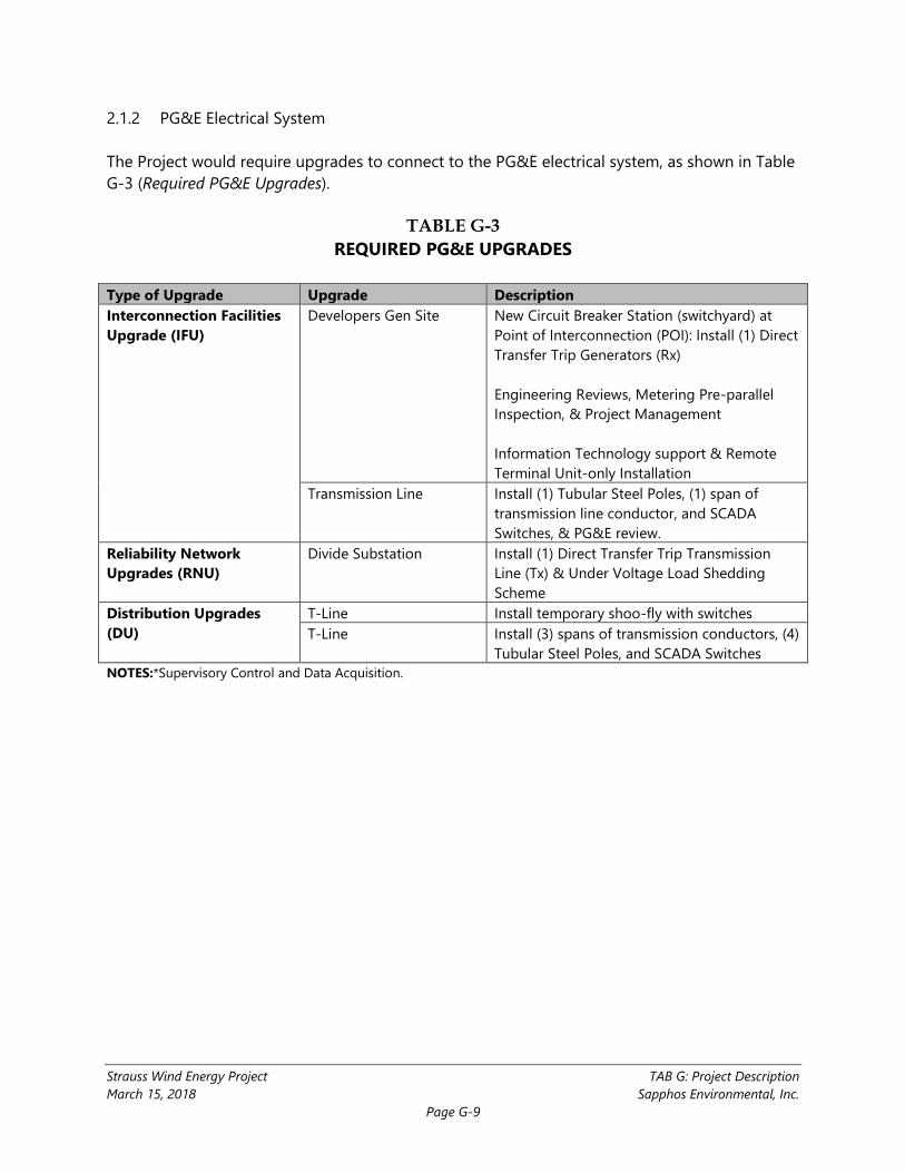
2.1.2 PG&E Electrical System
The Project would require upgrades to connect to the PG&E electrical system, as shown in Table
G-3 (Required PG&E Upgrades).
TABLE G-3
REQUIRED PG&E UPGRADES
Type of Upgrade Upgrade Description
Interconnection Facilities
Upgrade (IFU)
Developers Gen Site New Circuit Breaker Station (switchyard) at
Point of Interconnection (POI): Install (1) Direct
Transfer Trip Generators (Rx)
Engineering Reviews, Metering Pre-parallel
Inspection, & Project Management
Information Technology support & Remote
Terminal Unit-only Installation
Transmission Line Install (1) Tubular Steel Poles, (1) span of
transmission line conductor, and SCADA
Switches, & PG&E review.
Reliability Network
Upgrades (RNU)
Divide Substation Install (1) Direct Transfer Trip Transmission
Line (Tx) & Under Voltage Load Shedding
Scheme
Distribution Upgrades
(DU)
T-Line Install temporary shoo-fly with switches
T-Line Install (3) spans of transmission conductors, (4)
Tubular Steel Poles, and SCADA Switches
NOTES:*Supervisory Control and Data Acquisition.
Strauss Wind Energy Project TAB G: Project Description
March 15, 2018 Sapphos Environmental, Inc.
Page G-10
3.0 PROJECT COMPONENTS
3.1 Wind Turbine Generators
3.1.1 Layout and Design
The Project proposes up to 30 WTGs as shown on Site Plan (in the Maps tab), each with a
nameplate capacity of 1.79 or 3.8 MW. The WTGs would consist of 6 each GE 1.79 MW WTGs,
and 24 each GE 3.8 MW WTGs. The 1.79-MW WTGs would be 427 feet (130 meters) in total
height from foundation to blade tip, and the 3.8-MW WTGs would be 492 feet (150 meters)
from foundation to blade tip. The six 1.79-MW WTGs are generally proposed in the southeastern
portion of the Project area. The remaining twenty-four 3.8-MW WTGs are proposed throughout
the site generally on prominent ridgelines. Photographs of these WTGs are shown on Figure G-6
(GE 3.8 MW Wind Turbine) and Figure G-7 (GE 1.79 MW Wind Turbine). Table G-4 (Wind Turbine
Generator Model Component Specifications) provides detailed information relating to tower and
blade dimensions and total system height. Additionally, Appendix M (Wind Turbine
Specifications) contains detailed information relating to tower and blade dimensions and total
system height; dimensions and weight of components for transport; colors; noise characteristics,
including maximum noise levels; materials and construction; energy generation capacity; any
equipment outside the nacelle (e.g., transformers); rotational speed and speed at blade tips
(typical, min., and max.); and operational safety record. Locations for WTGs were determined
based on the optimum wind resource on the Project site, and avoidance of environmental
resources such as the State Coastal Zone; archaeological sites; critical habitat for the California
red legged frog and Gaviota tar plant; federally designated wetlands and blue-line streams; and
sensitive plant communities such as Coast Live Oak Woodland, Tanoak Forrest, and Central
Coast Arroyo Willow Riparian Forest. In order to avoid potential impacts to sensitive receptors
from potential noise impacts, Turbine No. 20 was moved approximately 218 feet to the
northwest to avoid a nonparticipating single-family residence located approximately 1,700 feet
east of the Project boundary. The original Lompoc Wind Energy Project proposed 65 1.5-MW
WTGs. The Project reduces the total number of turbines proposed to 30, which is a 54 percent
reduction in the number of turbines.
Strauss Wind Energy Project TAB G: Project Description
March 15, 2018 Sapphos Environmental, Inc.
Page G-11
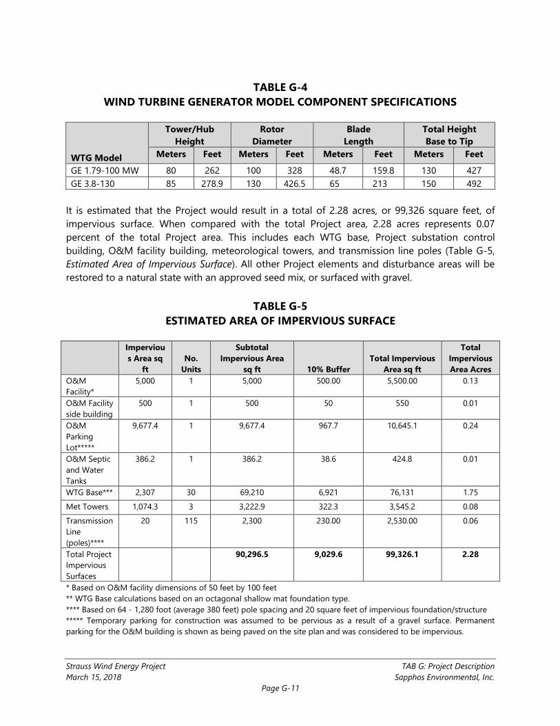
TABLE G-4
WIND TURBINE GENERATOR MODEL COMPONENT SPECIFICATIONS
WTG Model
Tower/Hub
Height
Rotor
Diameter
Blade
Length
Total Height
Base to Tip
Meters Feet Meters Feet Meters Feet Meters Feet
GE 1.79-100 MW 80 262 100 328 48.7 159.8 130 427
GE 3.8-130 85 278.9 130 426.5 65 213 150 492
It is estimated that the Project would result in a total of 2.28 acres, or 99,326 square feet, of
impervious surface. When compared with the total Project area, 2.28 acres represents 0.07
percent of the total Project area. This includes each WTG base, Project substation control
building, O&M facility building, meteorological towers, and transmission line poles (Table G-5,
Estimated Area of Impervious Surface). All other Project elements and disturbance areas will be
restored to a natural state with an approved seed mix, or surfaced with gravel.
TABLE G-5
ESTIMATED AREA OF IMPERVIOUS SURFACE
Imperviou
s Area sq
ft
No.
Units
Subtotal
Impervious Area
sq ft 10% Buffer
Total Impervious
Area sq ft
Total
Impervious
Area Acres
O&M
Facility*
5,000 1 5,000 500.00 5,500.00 0.13
O&M Facility
side building
500 1 500 50 550 0.01
O&M
Parking
Lot*****
9,677.4 1 9,677.4 967.7 10,645.1 0.24
O&M Septic
and Water
Tanks
386.2 1 386.2 38.6 424.8 0.01
WTG Base*** 2,307 30 69,210 6,921 76,131 1.75
Met Towers 1,074.3 3 3,222.9 322.3 3,545.2 0.08
Transmission
Line
(poles)****
20 115 2,300 230.00 2,530.00 0.06
Total Project
Impervious
Surfaces
90,296.5 9,029.6 99,326.1 2.28
* Based on O&M facility dimensions of 50 feet by 100 feet
** WTG Base calculations based on an octagonal shallow mat foundation type.
**** Based on 64 - 1,280 foot (average 380 feet) pole spacing and 20 square feet of impervious foundation/structure
***** Temporary parking for construction was assumed to be pervious as a result of a gravel surface. Permanent
parking for the O&M building is shown as being paved on the site plan and was considered to be impervious.
Strauss Wind Energy Project TAB G: Project Description
March 15, 2018 Sapphos Environmental, Inc.
Page G-12
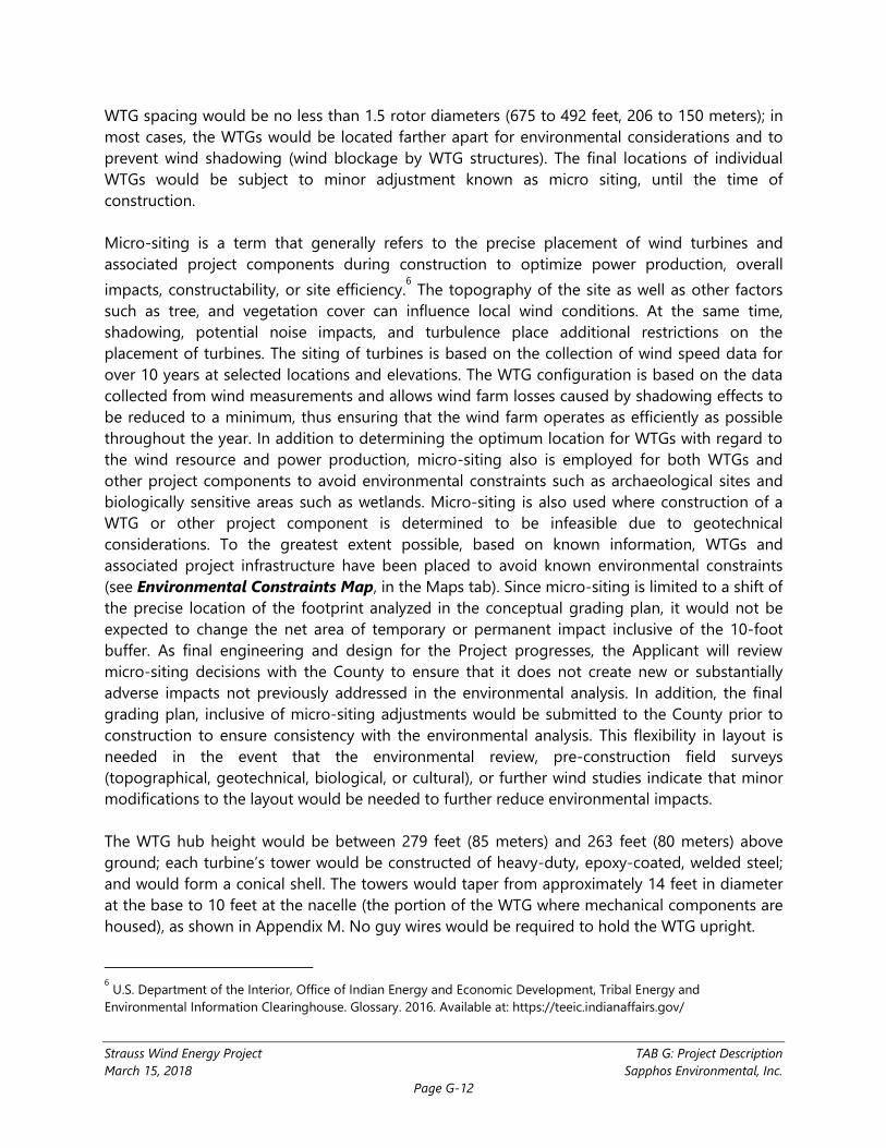
WTG spacing would be no less than 1.5 rotor diameters (675 to 492 feet, 206 to 150 meters); in
most cases, the WTGs would be located farther apart for environmental considerations and to
prevent wind shadowing (wind blockage by WTG structures). The final locations of individual
WTGs would be subject to minor adjustment known as micro siting, until the time of
construction.
Micro-siting is a term that generally refers to the precise placement of wind turbines and
associated project components during construction to optimize power production, overall
impacts, constructability, or site efficiency.6 The topography of the site as well as other factors
such as tree, and vegetation cover can influence local wind conditions. At the same time,
shadowing, potential noise impacts, and turbulence place additional restrictions on the
placement of turbines. The siting of turbines is based on the collection of wind speed data for
over 10 years at selected locations and elevations. The WTG configuration is based on the data
collected from wind measurements and allows wind farm losses caused by shadowing effects to
be reduced to a minimum, thus ensuring that the wind farm operates as efficiently as possible
throughout the year. In addition to determining the optimum location for WTGs with regard to
the wind resource and power production, micro-siting also is employed for both WTGs and
other project components to avoid environmental constraints such as archaeological sites and
biologically sensitive areas such as wetlands. Micro-siting is also used where construction of a
WTG or other project component is determined to be infeasible due to geotechnical
considerations. To the greatest extent possible, based on known information, WTGs and
associated project infrastructure have been placed to avoid known environmental constraints
(see Environmental Constraints Map, in the Maps tab). Since micro-siting is limited to a shift of
the precise location of the footprint analyzed in the conceptual grading plan, it would not be
expected to change the net area of temporary or permanent impact inclusive of the 10-foot
buffer. As final engineering and design for the Project progresses, the Applicant will review
micro-siting decisions with the County to ensure that it does not create new or substantially
adverse impacts not previously addressed in the environmental analysis. In addition, the final
grading plan, inclusive of micro-siting adjustments would be submitted to the County prior to
construction to ensure consistency with the environmental analysis. This flexibility in layout is
needed in the event that the environmental review, pre-construction field surveys
(topographical, geotechnical, biological, or cultural), or further wind studies indicate that minor
modifications to the layout would be needed to further reduce environmental impacts.
The WTG hub height would be between 279 feet (85 meters) and 263 feet (80 meters) above
ground; each turbine’s tower would be constructed of heavy-duty, epoxy-coated, welded steel;
and would form a conical shell. The towers would taper from approximately 14 feet in diameter
at the base to 10 feet at the nacelle (the portion of the WTG where mechanical components are
housed), as shown in Appendix M. No guy wires would be required to hold the WTG upright.
6 U.S. Department of the Interior, Office of Indian Energy and Economic Development, Tribal Energy and
Environmental Information Clearinghouse. Glossary. 2016. Available at: https://teeic.indianaffairs.gov/
Strauss Wind Energy Project TAB G: Project Description
March 15, 2018 Sapphos Environmental, Inc.
Page G-13
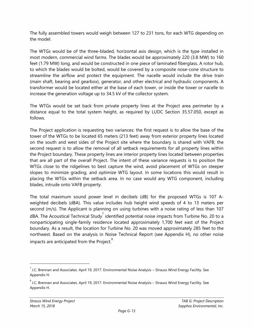
The fully assembled towers would weigh between 127 to 231 tons, for each WTG depending on
the model.
The WTGs would be of the three-bladed, horizontal axis design, which is the type installed in
most modern, commercial wind farms. The blades would be approximately 220 (3.8 MW) to 160
feet (1.79 MW) long, and would be constructed in one piece of laminated fiberglass. A rotor hub,
to which the blades would be bolted, would be covered by a composite nose-cone structure to
streamline the airflow and protect the equipment. The nacelle would include the drive train
(main shaft, bearing and gearbox), generator, and other electrical and hydraulic components. A
transformer would be located either at the base of each tower, or inside the tower or nacelle to
increase the generation voltage up to 34.5 kV of the collector system.
The WTGs would be set back from private property lines at the Project area perimeter by a
distance equal to the total system height, as required by LUDC Section 35.57.050, except as
follows.
The Project application is requesting two variances: the first request is to allow the base of the
tower of the WTGs to be located 65 meters (213 feet) away from exterior property lines located
on the south and west sides of the Project site where the boundary is shared with VAFB; the
second request is to allow the removal of all setback requirements for all property lines within
the Project boundary. These property lines are interior property lines located between properties
that are all part of the overall Project. The intent of these variance requests is to position the
WTGs close to the ridgelines to best capture the wind, avoid placement of WTGs on steeper
slopes to minimize grading, and optimize WTG layout. In some locations this would result in
placing the WTGs within the setback area. In no case would any WTG component, including
blades, intrude onto VAFB property.
The total maximum sound power level in decibels (dB) for the proposed WTGs is 107 A-
weighted decibels (dBA). This value includes hub height wind speeds of 4 to 13 meters per
second (m/s). The Applicant is planning on using turbines with a noise rating of less than 107
dBA. The Acoustical Technical Study7 identified potential noise impacts from Turbine No. 20 to a
nonparticipating single-family residence located approximately 1,700 feet east of the Project
boundary. As a result, the location for Turbine No. 20 was moved approximately 285 feet to the
northwest. Based on the analysis in Noise Technical Report (see Appendix H), no other noise
impacts are anticipated from the Project.8
7 J.C. Brennan and Associates. April 19, 2017. Environmental Noise Analysis – Strauss Wind Energy Facility. See
Appendix H.
8 J.C. Brennan and Associates. April 19, 2017. Environmental Noise Analysis – Strauss Wind Energy Facility. See
Appendix H.
Strauss Wind Energy Project TAB G: Project Description
March 15, 2018 Sapphos Environmental, Inc.
Page G-14
After Federal Aviation Administration (FAA) Determination of No Hazard (DNH) certification has
been issued for a specific turbine location, micro-siting of more than1 arc second, approximately
100 feet requires reapplication.
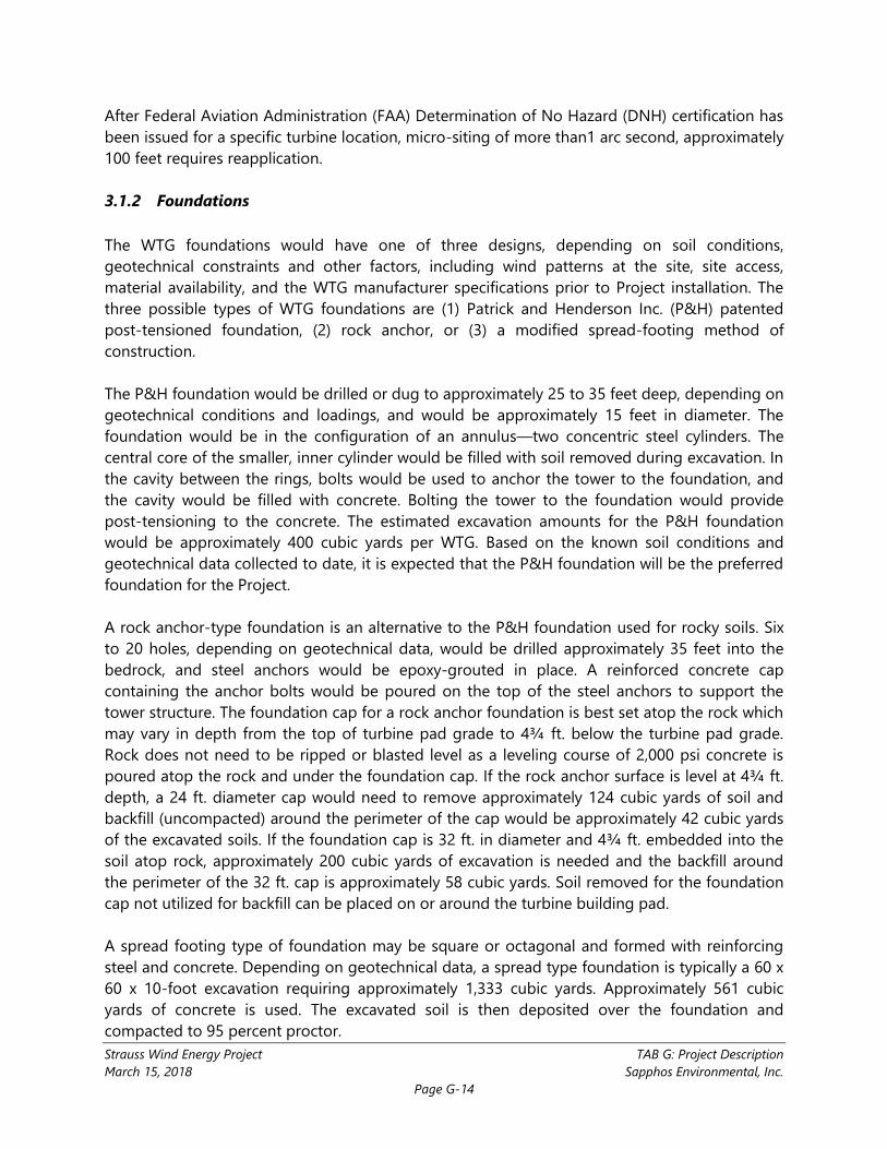
3.1.2 Foundations
The WTG foundations would have one of three designs, depending on soil conditions,
geotechnical constraints and other factors, including wind patterns at the site, site access,
material availability, and the WTG manufacturer specifications prior to Project installation. The
three possible types of WTG foundations are (1) Patrick and Henderson Inc. (P&H) patented
post-tensioned foundation, (2) rock anchor, or (3) a modified spread-footing method of
construction.
The P&H foundation would be drilled or dug to approximately 25 to 35 feet deep, depending on
geotechnical conditions and loadings, and would be approximately 15 feet in diameter. The
foundation would be in the configuration of an annulus—two concentric steel cylinders. The
central core of the smaller, inner cylinder would be filled with soil removed during excavation. In
the cavity between the rings, bolts would be used to anchor the tower to the foundation, and
the cavity would be filled with concrete. Bolting the tower to the foundation would provide
post-tensioning to the concrete. The estimated excavation amounts for the P&H foundation
would be approximately 400 cubic yards per WTG. Based on the known soil conditions and
geotechnical data collected to date, it is expected that the P&H foundation will be the preferred
foundation for the Project.
A rock anchor-type foundation is an alternative to the P&H foundation used for rocky soils. Six
to 20 holes, depending on geotechnical data, would be drilled approximately 35 feet into the
bedrock, and steel anchors would be epoxy-grouted in place. A reinforced concrete cap
containing the anchor bolts would be poured on the top of the steel anchors to support the
tower structure. The foundation cap for a rock anchor foundation is best set atop the rock which
may vary in depth from the top of turbine pad grade to 4¾ ft. below the turbine pad grade.
Rock does not need to be ripped or blasted level as a leveling course of 2,000 psi concrete is
poured atop the rock and under the foundation cap. If the rock anchor surface is level at 4¾ ft.
depth, a 24 ft. diameter cap would need to remove approximately 124 cubic yards of soil and
backfill (uncompacted) around the perimeter of the cap would be approximately 42 cubic yards
of the excavated soils. If the foundation cap is 32 ft. in diameter and 4¾ ft. embedded into the
soil atop rock, approximately 200 cubic yards of excavation is needed and the backfill around
the perimeter of the 32 ft. cap is approximately 58 cubic yards. Soil removed for the foundation
cap not utilized for backfill can be placed on or around the turbine building pad.
A spread footing type of foundation may be square or octagonal and formed with reinforcing
steel and concrete. Depending on geotechnical data, a spread type foundation is typically a 60 x
60 x 10-foot excavation requiring approximately 1,333 cubic yards. Approximately 561 cubic
yards of concrete is used. The excavated soil is then deposited over the foundation and
compacted to 95 percent proctor.
Strauss Wind Energy Project TAB G: Project Description
March 15, 2018 Sapphos Environmental, Inc.
Page G-15
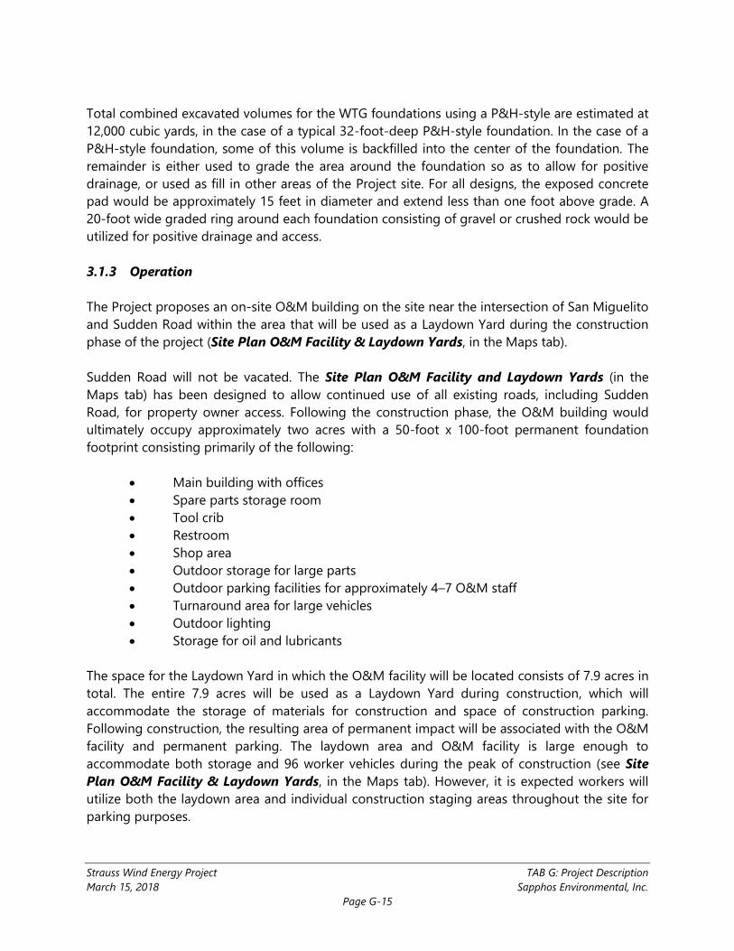
Total combined excavated volumes for the WTG foundations using a P&H-style are estimated at
12,000 cubic yards, in the case of a typical 32-foot-deep P&H-style foundation. In the case of a
P&H-style foundation, some of this volume is backfilled into the center of the foundation. The
remainder is either used to grade the area around the foundation so as to allow for positive
drainage, or used as fill in other areas of the Project site. For all designs, the exposed concrete
pad would be approximately 15 feet in diameter and extend less than one foot above grade. A
20-foot wide graded ring around each foundation consisting of gravel or crushed rock would be
utilized for positive drainage and access.
3.1.3 Operation
The Project proposes an on-site O&M building on the site near the intersection of San Miguelito
and Sudden Road within the area that will be used as a Laydown Yard during the construction
phase of the project (Site Plan O&M Facility & Laydown Yards, in the Maps tab).
Sudden Road will not be vacated. The Site Plan O&M Facility and Laydown Yards (in the
Maps tab) has been designed to allow continued use of all existing roads, including Sudden
Road, for property owner access. Following the construction phase, the O&M building would
ultimately occupy approximately two acres with a 50-foot x 100-foot permanent foundation
footprint consisting primarily of the following:
Main building with offices
Spare parts storage room
Tool crib
Restroom
Shop area
Outdoor storage for large parts
Outdoor parking facilities for approximately 4–7 O&M staff
Turnaround area for large vehicles
Outdoor lighting
Storage for oil and lubricants
The space for the Laydown Yard in which the O&M facility will be located consists of 7.9 acres in
total. The entire 7.9 acres will be used as a Laydown Yard during construction, which will
accommodate the storage of materials for construction and space of construction parking.
Following construction, the resulting area of permanent impact will be associated with the O&M
facility and permanent parking. The laydown area and O&M facility is large enough to
accommodate both storage and 96 worker vehicles during the peak of construction (see Site
Plan O&M Facility & Laydown Yards, in the Maps tab). However, it is expected workers will
utilize both the laydown area and individual construction staging areas throughout the site for
parking purposes.
Strauss Wind Energy Project TAB G: Project Description
March 15, 2018 Sapphos Environmental, Inc.
Page G-16
The O&M facility will have gated access with partial or full perimeter fencing. An O&M facility
within the Project boundary will minimize response time and related down time to power
delivery related operations. The O&M facility would be made of a pre-engineered metal of a
neutral color. During construction, the O&M facility area would be leveled, graded and
compacted. Water to service the O&M facility would be provided via a new well. A 5,000-gallon
water storage tank would be installed to supply water for firefighting. The fire water tank would
only be used for fire water storage. Less than 250 gallons per day of potable water would be
needed to serve the O&M facility. This water would be provided through an onsite well
described below. Water usage at the O&M facility will be used predominantly for sanitation
purposes for the O&M staff. Water may be used to clean the blades as needed during
operations, but in no case more than once yearly.
Potable water for the O&M facility will be provided by an onsite well located approximately
4,000 feet northeast of the O&M facility along San Miguelito Road. A feasibility analysis has
determined that this well is adequate to serve the O&M facility (Appendix O, Assessment of
Groundwater Well Feasibility). Depth to water in a well at this location would likely be less than
200 feet. Production capacity from a well at this location could be up to 20 gallons per minute
(Appendix O, Assessment of Groundwater Well Feasibility).
Effluent from the office drains would be disposed of through a proposed leach line septic
system. A Percolation Test Study has been submitted for the proposed site (Appendix K,
Percolation Study). Any new or used oils would be stored on a concrete slab with a containment
curb to contain any spills. The O&M facility site vicinity is characterized by native soils with low
permeability, as well as a high ground water table. An in-ground septic disposal system requires
soil with adequate permeability to absorb leachates after solids are deposited in the septic tank.
Additionally, a desired clearance of around 10 feet is needed from the leach lines to the ground
water table. At the O&M facility site, ground water was encountered at 19 to 20 feet below the
surface, which rose to within 8 feet of the surface in soil borings (Appendix O).
Sewage flow generated by the O&M facility has been estimated at 250 gallons per day, which is
conservative since the various plumbing codes typically estimate roughly 20 gallons per person
per day, for a typical office and five to seven employees are expected to occupy the O&M
facility.
Given the existing conditions at the O&M site, a “Mounding” soil absorption system is a logical
choice for sewage disposal. A mounding system is a soil absorption system that is elevated
above the natural ground surface. Imported, highly permeable soils are used to replace native
materials to provide a sufficient leaching medium, and adequate clearance from ground water.
As shown on Site Plan O&M Facility & Laydown Yards (in the Maps tab), the system is similar
to conventional in ground septic disposal, and includes a septic tank to remove solids and
grease, and a 4-inch pipeline at 3 percent slope to a distribution box, and leach lines. The leach
lines are location in the east “panhandle” of the O&M facility, which is an area that will receive as
much as 10 feet of fill as a result of grading. The septic tank will likely be 1,000 gallons or
greater. The system may require roughly 150 feet of leaching lines, but this will be dependent on

Strauss Wind Energy Project TAB G: Project Description
March 15, 2018 Sapphos Environmental, Inc.
Page G-17
the quality of the imported soil and final engineering calculations.
As discussed above, the domestic water demand has been estimated to be 250 gallons per day
or less. Again, this is considered a conservative estimate since only five to seven employees will
occupy the facility. Again, typical plumbing code values for offices usually do not exceed 20
gallons per day per employee.
The proposed source of domestic and fire water supply is Site #2, as described in the Cleath-
Harris Geologists, Inc. (CHG) groundwater feasibility study. This source is estimated to yield up
to 20 gallons per minute of potentially potable water. The CHG indicates some treatment may
be required. This source is approximately 4,000 feet northeast of the O&M site. From the well
site, ground water will be pumped into an in-ground line, and sufficiently pressurized to reach
the O&M facility. At the O&M facility, water would be deposited into an on-site storage tank of
sufficient capacity to provide the domestic demand and the needed fire flow. A dedicated pump
would pressurize a fire water line, fire hydrant, and a building sprinkler system. The O&M site
plan shows a fire hydrant fronting the facility, as well as the storage tank and pumps. Another
dedicated pump would pressurize the domestic system. Final sizing of all components will be
determined during final engineering
3.1.4 Wind Turbine Generators
The WTGs would be equipped with sensors and yaw and pitch controls to adapt to different
wind speeds and directions to maximize power output. The yaw drive ensures that the WTG is
producing the maximum amount of electrical energy at all times by keeping the turbine blade
facing into the wind as the wind direction changes. The pitch is the angle of the turbine blade.
The WTGs would be microprocessor controlled and operating data would be transmitted to the
on-site O&M facility and an offsite remote operation center for system monitoring and control.
The remote operation center is a data collection center that could be anywhere, including the
Applicant’s headquarters. Communications between the WTGs and the remote operations
center are completed via digital communication protocols. This control system would measure
and automatically control operations, including the following functions:
Power regulation over a wide range of wind speeds, including startup, shutdown,
and generator-grid connection.
Yaw control, including protection against damage due to abnormal operating
conditions or extreme environmental conditions.
Safety monitoring, enabling automatic shutdown of the WTGs independent of all
other controls, thereby protecting them from unsafe conditions.
Monitoring sensor data for rotor speed, generator current, electrical load, nacelle
vibration, yaw error, pitch control, system-hydraulic pressure, temperature, and
more.

Strauss Wind Energy Project TAB G: Project Description
March 15, 2018 Sapphos Environmental, Inc.
Page G-18
The controller would adjust the blade pitch periodically using a hydraulic or electric actuator.
The actuator would regulate blade pitch to achieve smooth and consistent power curves as wind
speed and air density changes. The actuator would adjust the blades’ angle-of-attack with the
prevailing wind and air density to optimize performance. The rotor would normally be stopped
by either yawing the blades out of the wind or by rotating the blades to increase their
aerodynamic drag. A fail-safe hydraulic brake would also be installed on the high-speed shaft,
which would be used primarily to prevent rotation during maintenance.
If a critical control parameter deviated from its normal operating range, the controller would
automatically shut down the WTG and notify the operating technician(s) of the fault. In many
situations, the controller would analyze the data and restart the WTG if the fault were corrected
or the operating conditions returned to normal. If the fault reoccurred, the controller might
require a manual start, for which a technician would have to be present to restart the WTG.
Each WTG controller would communicate via fiber-optic cables to the Project O&M facility. This
configuration would enable the facility to be controlled to maximize output, minimize
maintenance costs and downtime, produce operations reports, and ensure compliance under
the Project’s performance warranties.
In accordance with good utility practice, routine inspections would be performed on all electrical
connections periodically, and any faulty cables or damaged insulators would be replaced as
needed for the underground/overhead collection system within the Project area.
A possibility exists that severe storms might result in occasional downed power lines or poles. In
this case, procedures outlined in the emergency response plan and the standard operating
procedures developed for the Project would address problems such as power outages, lightning
storms, excessive rains, landslides or mudslides, ice storms, and other weather-related incidents.
3.1.5 Additional Safety Features
Each WTG blade is an independent fail safe system, and can stop the rotor from going in
overspeed. As a result, the rotor can be brought to a halt under all foreseeable conditions. Brake
pads on the disc brake system would be spring-loaded against the disc, and power would be
required to keep the pads away from the disc. If power were lost, the brakes would immediately
be mechanically activated. The aerodynamic braking system would also be configured so that if
power were lost, it would be immediately activated. If an emergency stop were executed, remote
restarting would not be possible. The WTG would need to be inspected in person and the stop-
fault reset manually before automatic reactivation. Each WTG also would be equipped with a
brake that generally would be used to keep the rotor from moving while maintenance routines
or inspections that require a stationary rotor are performed.
If the Supervisory Control and Data Acquisition (SCADA) system malfunctioned or failed, or if
transmissions/communication were interrupted, the wind turbines are designed to safely self-
operate without the requirement of a SCADA or other external monitoring system. Each turbine
Strauss Wind Energy Project TAB G: Project Description
March 15, 2018 Sapphos Environmental, Inc.
Page G-19
has installed its own controller system which monitors and controls all components and
elements, and in case of an error or abnormality, disconnects from the grid and stops the
turbine. Modern wind farms are equipped with SCADA systems to facilitate remote monitoring,
analysis and control to improve performance and quality of the energy generated. In the rare
event of a communication loss of a turbine with the SCADA central computer or of the SCADA
central computer with the operation centers a wind turbine will continue to operate as long as it
is error free. A service technician is then dispatched to manually operate turbines when needed
and restore communication as quickly as possible.
The safety systems of all WTGs would comply with the codes set forth by the Occupational
Health and Safety Administration (OSHA), the American National Standards Institute (ANSI), and
European Union (EU) OSHA standards.
Each WTG also would be equipped with vibration, temperature, and fire detection systems in the
nacelle and tower. The fire detection system would be connected to the main controller and the
central SCADA system. In the event of a fire fault or excess vibration or temperature, the WTG
would be halted immediately, and an alarm condition would be activated in the control system
that could send a page or message to a cell phone of the on-call operators or the local fire
district (first responders), as required.
The nacelle would be accessed using a ladder located inside the tower. Internal ladders and
maintenance areas inside the tower and nacelle would be equipped with safety provisions for
securing lifelines and safety belts and conform to or exceed ANSI 14.3-1974 (Safety
Requirements for Ladders).
The WTGs would be equipped with a lightning protection system that connects the blades,
nacelle, and tower to the earthing (grounding) system at the base of the tower. Because the
rotor blades would be nonmetallic, they normally would not act as a discharge path for
lightning; however, as the highest point of the WTG, the blades sometimes would provide the
path of least resistance for a lightning strike. To protect the blades, they would be constructed
with an internal copper conductor extending from the blade tip down to the rotor hub, which
would be connected to the main shaft and establish a path through the gearbox and nacelle bed
frame to the tower base, down to the grounding system embedded underground. An additional
lightning rod would extend above the wind vane and anemometer at the rear of the nacelle.
Both the rear lightning rod and blades would have conductive paths to the nacelle bed frame,
which connects to the tower. The tower base would be connected to the earthing system at
diametrically opposed points. The earthing system would consist of a copper ring conductor
connected to earthing rods driven into the ground at diametrically opposed points outside of
the foundation. The earthing system, with an acceptable resistance (less than 2 ohms), would
provide a firm-grounding path to divert harmful stray surge voltages away from the WTG. The
controllers and communication interfaces to the Project central control system would use fiber-
optic cables and optical signal conversion systems, to protect these systems from stray surges.
Strauss Wind Energy Project TAB G: Project Description
March 15, 2018 Sapphos Environmental, Inc.
Page G-20
This analysis assumes that the Federal Aviation Administration (FAA) will require a synchronized,
flashing, red light would be mounted on the top of the nacelle of the WTG located at the end of
each WTG string; additional WTGs within the string would also have such a light so that the
maximum distance between lit WTGs would be no greater than 2,640 feet. These lights would be
placed in compliance with FAA guidelines.
The Project site is located entirely within the County’s High Fire Hazard Area. Some firefighting
equipment would be located at the Project Substation site, maintenance yard, and in vehicles.
Fire features and best management practices within the project site would include service and
access roads, which could serve as firebreaks, and regular clearing of vegetation from areas
around transformers and riser poles. Firefighting equipment would be stored at the onsite
substation and in the O&M Building. A 20 pound CO2 fire extinguisher for small fires would be
stored at the substation and at the O&M Building for small fires. In addition, trucks would be
equipped with one 5-pound standard fire extinguisher. The design of the substation would take
into account local permitting and may be adjusted accordingly. Furthermore, a safety and
emergency response plan will be developed in conjunction with the local Fire Marshall.
The substation surface would be covered with a layer of rock. This rock layer would act as a fire
barrier. In addition, spatial separation of transformers and other equipment would be provided
for in the design to prevent fire propagation. The substation would meet or exceed Institute of
Electrical and Electronics Engineers (IEEE)-979 Substation Fire Protection. Detection and
extinguishing equipment shall be installed in accordance with all applicable national and local
codes.
Safety signage would be posted where necessary around WTGs, transformers, and other high-
voltage facilities, and along roads, in conformance with applicable State and Federal regulations.
A safety policy plan shall be developed and will be included as part of the mitigation
requirements.
For safety and protection, wind farms have multiple layers of security to prevent compromising
the wind farm and the connected Bulk Electric System. The physical security is provided by
installing locked gates at the entrance to all access roads. In addition, all turbines are locked as
well as are the Project substation and control house, which are additionally fenced by an 8-foot
barbed wire reinforced fence. Electronic access to any SCADA access point is protected by at
least two layers of security using high industry standard VPN technology and secure passwords
and 24/7 remote monitoring. In addition, the use of surveillance cameras provides round-the-
clock eyes on the wind farm and its SCADA system, reporting any and all suspected intrusions or
abnormalities to field personnel and the Asset Management Department. Remote Monitoring
Operations Rooms and turbine manufacturer’s Remote Operation Centers require keycard
access to prevent unauthorized access.

Strauss Wind Energy Project TAB G: Project Description
March 15, 2018 Sapphos Environmental, Inc.
Page G-21
3.1.6 Wind Turbine Generator Certification
The Project would use only WTGs that have achieved design certification by a reputable and
experienced third-party verification institute, such as DNV GL, TÜV, or other comparable
certification bodies for wind turbines, and demonstrate a design life of at least 20 years. The
factors involved in certifying WTG design include safety and control system concepts,
addressing rotating and still turbine states, and load bearing confirmation. When approved,
specific components, such as blades, hub, drive train, generator, safety system, tower, yaw
system, and electrical installations, would be reviewed and approved according to minimum
standards established by third-party verification institutes. In addition the Applicant will employ
a reputable Independent Engineering firm (IE) review construction supervision procedures,
including materials testing, compliance with the design certificate, quality assurance reports and
procedures, corrosion protection, and others. The IE also reviews standards and documentation
for supervision during the transportation, erection, and commissioning of the WTGs.
Operational testing of turbine models performed by the laboratories includes measurement of
power curves, noise emissions, and loads and stresses, including wind loads imposed on the
tower, foundation, drive train, blades, nacelle frame, and power quality. Test data are evaluated
for plausibility, and compared with the original calculations and mathematical models used for
the design.
3.2 On-Site Access Roads
Numerous dirt roads are present throughout the Project area and maintained by the property
owners for agricultural operations. To provide access during construction and operations, 2.6
miles of the existing roads would be improved and widened from their existing widths of 10 to
14 feet, to 22 feet. Some road sections would need to be 16 feet wide with 10-foot compacted
shoulders on each side to allow crane travel between WTG locations. These shoulders would be
reclaimed at the end of the Project. The width of construction access roads will vary between 22
to 40 feet to accommodate roadway cut and fill, and necessary equipment turning radii and
turn-outs. The roadways would be restored to a 16-foot width upon completion of WTG
installation.
In addition, approximately 9.9 miles of new roads would be constructed. Short sections of
roadway would also be built in other parts of the Project area. The road work would include
trenching and installing underground electrical distribution lines and communication cables.
Strauss Wind Energy Project TAB G: Project Description
March 15, 2018 Sapphos Environmental, Inc.
Page G-22
Crossings of minor drainage channels would be accomplished with culverts or at-grade
crossings. According to the preliminary grading plan, cut volumes for the entire Project are
estimated to be 665,025 cubic yards (cy), and fill volumes are estimated at 623,025 cy, leaving a
net differential value of 42,000 cy for all the required Project earthwork. As a result of shrinkage
and settling, all earthwork is expected to be balanced on site. All grading would be subject to a
final, approved grading and erosion control plan to minimize erosion and ensure adequate
slope stabilization. Areas of temporary disturbance would be revegetated following the
roadwork.
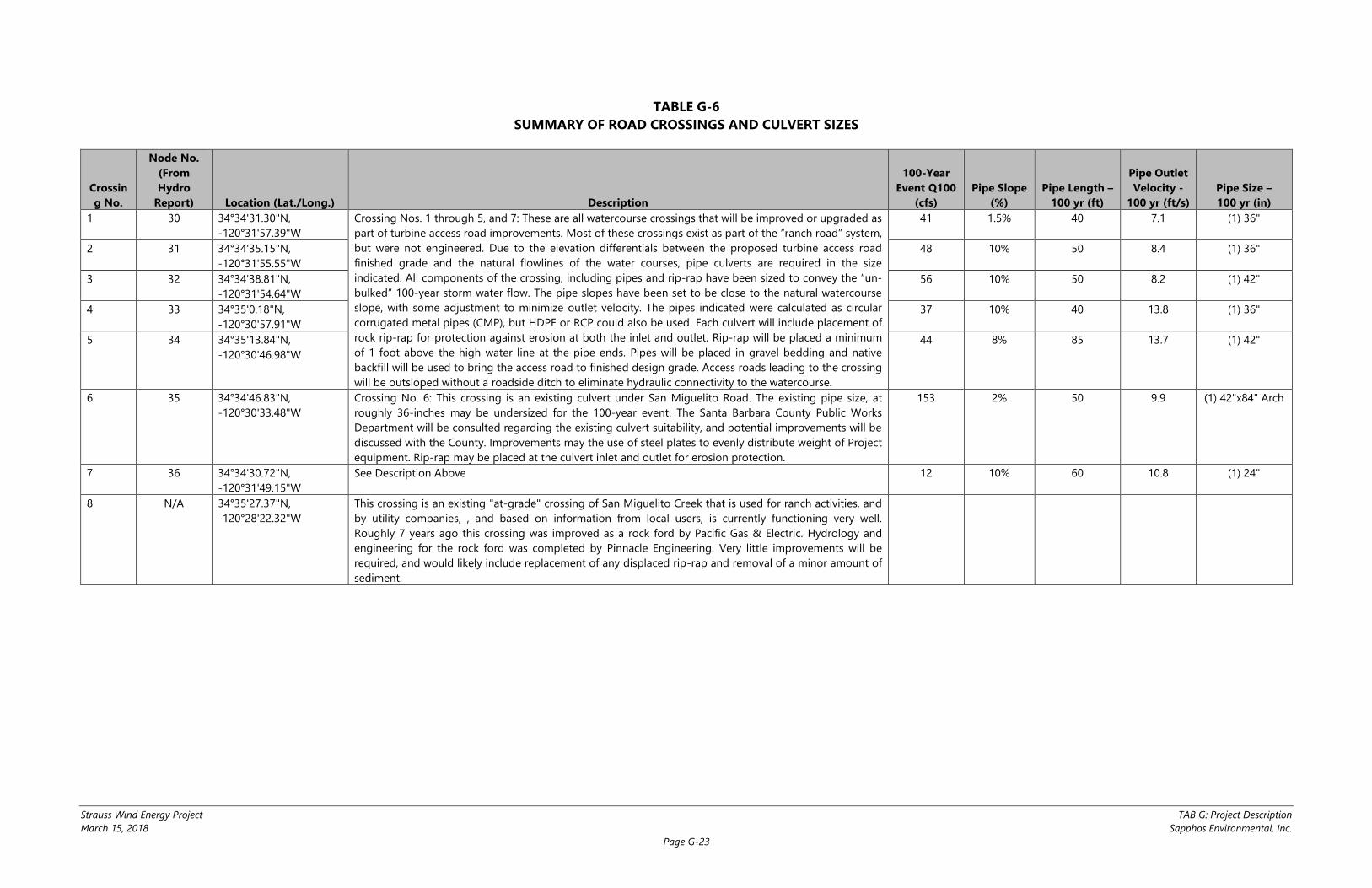
Table G-6 (Summary of Road Crossings and Culvert Sizes) provides a summary of road crossings
and associated culvert sizes required for the construction of Project road improvements. These
crossings are identified in Appendix G (Strauss Wind Farm Hydrologic Analysis).
Strauss Wind Energy Project TAB G: Project Description
March 15, 2018 Sapphos Environmental, Inc.
Page G-23
TABLE G-6
SUMMARY OF ROAD CROSSINGS AND CULVERT SIZES
Crossin
g No.
Node No.
(From
Hydro
Report) Location (Lat./Long.) Description
100-Year
Event Q100
(cfs)
Pipe Slope
(%)
Pipe Length –
100 yr (ft)
Pipe Outlet
Velocity -
100 yr (ft/s)
Pipe Size –
100 yr (in)
1 30 34°34'31.30"N,
-120°31'57.39"W
Crossing Nos. 1 through 5, and 7: These are all watercourse crossings that will be improved or upgraded as
part of turbine access road improvements. Most of these crossings exist as part of the “ranch road” system,
but were not engineered. Due to the elevation differentials between the proposed turbine access road
finished grade and the natural flowlines of the water courses, pipe culverts are required in the size
indicated. All components of the crossing, including pipes and rip-rap have been sized to convey the “un-
bulked” 100-year storm water flow. The pipe slopes have been set to be close to the natural watercourse
slope, with some adjustment to minimize outlet velocity. The pipes indicated were calculated as circular
corrugated metal pipes (CMP), but HDPE or RCP could also be used. Each culvert will include placement of
rock rip-rap for protection against erosion at both the inlet and outlet. Rip-rap will be placed a minimum
of 1 foot above the high water line at the pipe ends. Pipes will be placed in gravel bedding and native
backfill will be used to bring the access road to finished design grade. Access roads leading to the crossing
will be outsloped without a roadside ditch to eliminate hydraulic connectivity to the watercourse.
41 1.5% 40 7.1 (1) 36"
2 31 34°34'35.15"N,
-120°31'55.55"W
48 10% 50 8.4 (1) 36"
3 32 34°34'38.81"N,
-120°31'54.64"W
56 10% 50 8.2 (1) 42"
4 33 34°35'0.18"N,
-120°30'57.91"W
37 10% 40 13.8 (1) 36"
5 34 34°35'13.84"N,
-120°30'46.98"W
44 8% 85 13.7 (1) 42"
6 35 34°34'46.83"N,
-120°30'33.48"W
Crossing No. 6: This crossing is an existing culvert under San Miguelito Road. The existing pipe size, at
roughly 36-inches may be undersized for the 100-year event. The Santa Barbara County Public Works
Department will be consulted regarding the existing culvert suitability, and potential improvements will be
discussed with the County. Improvements may the use of steel plates to evenly distribute weight of Project
equipment. Rip-rap may be placed at the culvert inlet and outlet for erosion protection.
153 2% 50 9.9 (1) 42"x84" Arch
7 36 34°34'30.72"N,
-120°31'49.15"W
See Description Above 12 10% 60 10.8 (1) 24"
8 N/A 34°35'27.37"N,
-120°28'22.32"W
This crossing is an existing "at-grade" crossing of San Miguelito Creek that is used for ranch activities, and
by utility companies, , and based on information from local users, is currently functioning very well.
Roughly 7 years ago this crossing was improved as a rock ford by Pacific Gas & Electric. Hydrology and
engineering for the rock ford was completed by Pinnacle Engineering. Very little improvements will be
required, and would likely include replacement of any displaced rip-rap and removal of a minor amount of
sediment.
Strauss Wind Energy Project TAB G: Project Description
March 15, 2018 Sapphos Environmental, Inc.
Page G-24
During construction and O&M, Project-related traffic would be routed to existing roads (subject
to improvement) and new roads developed for the Project. Project personnel and contractors
would adhere to speed limits commensurate with road types, traffic volumes, vehicle types, and
site-specific conditions, to ensure safe and efficient traffic flow. Signs would be placed along
public roads as directed by the County to identify speed limits, travel restrictions, and other
standard traffic control information. In addition, signs would be placed within the Project site in
accordance with the Project Safety Plan and EIR requirements. Project access roads will be
constructed with cattle guards where necessary to the standards of the both the landowners and
the Santa Barbara County Fire Department.
Station Road, which is an existing private road owned by a participating project landowner,
provides access to both private lands and the Sudden Peak Tracking Station located on the
summit of Sudden Peak. An approximately 900-foot segment of Station Road crosses into and
out of Vandenberg Air Force Base property. Use of this segment of road will provide access to
eight WTGs located in the southeastern portion of the Project (WTGs 21 through 28). The
Applicant has permission to access the entirety of this road, including the 900-foot segment of
road through VAFB through an easement (Appendix T, Station Road Easement Access
Documentation; Appendix L, VAFB Evacuation Agreement and Coordination Documentation).
Additionally, no grading or road improvement will take place on VAFB property.
During construction, access to adjacent properties would be maintained; however, some traffic
interruptions are anticipated. Local roadways have constraints that limit their potential to be
used by large trucks. In particular, San Miguelito Road has overhanging trees that may be lower
than the vertical clearances of the trucks, and its horizontal curves south of Miguelito County
Park have relatively small radii that would require improvement. In order to make these
improvements, traffic may need to be temporarily stopped using flaggers or traffic control
devices.
Informational signs would be used to inform public of temporary traffic hazards. Flaggers and
traffic cones would be utilized where any temporary changes to lane configuration are made
while making the necessary improvements. Deliveries of the turbine equipment would comply
with all permit requirements. Any routing plans, road restriction information, pilot vehicle
requirements, and other permit conditions required by the permits would be observed. If during
construction road widths are insufficient to accommodate traffic flow in both directions
simultaneously, then traffic may need to be temporarily stopped using flaggers or traffic control
devices.
3.3 On-Site Electrical Lines and Communication System
Each string of WTGs would be interconnected via 34.5-kV electrically insulated cables. These
cables would typically run underground. The power collection lines would transmit the power
from each string of WTGs to the Project Substation. The underground collector cables would
follow roads, where feasible. For the purposes of determining ground disturbance, small
sections of aboveground collection lines would be supported by single poles or H-frame

Strauss Wind Energy Project TAB G: Project Description
March 15, 2018 Sapphos Environmental, Inc.
Page G-25
structures. The overhead collection system would be constructed in conformance with good
utility practice, the National Electric Safety Code (NESC), ANSI, and the Avian Power Line
Interaction Committee (APLIC). At the Project Substation, the voltage would be increased from
34.5 kV to 115 kV to match the voltage of the PG&E grid at the Point of Interconnection.
Operation of the Project would be controlled by an integrated, automatic control system,
SCADA, which would be capable of monitoring all operational parameters and starting and
stopping each WTG. The SCADA system would transmit operating parameters and other data
from each WTG to the central computer. The system would allow remote control and
monitoring of individual WTGs and the entire project site locally and remotely. Communication
cables would be buried in the same trenches used for the electrical collector lines. Overhead
communications lines would be installed on the structures used for overhead lines. Either
overhead or underground communications lines would be routed to the control room and from
there to the closest access point of the preferred internet service provider.
3.4 Wind Resource Measurement
Prior to start of construction of the Project, meteorological data would be collected using
mobile sonic detection and ranging units (SODAR) and a temporary meteorological towers that
would record weather data necessary to determine the most efficient operational strategy for
the WTGs. The data collected would include wind speed and direction, temperature, humidity,
barometric pressure, and rainfall. The data collected would be used to supplement over five
years of wind data collected from meteorological towers that were once present at the Project
site. As a result of their small footprint and mobility, and no permanent ground disturbance,
SODAR units and temporary met towers can be transported easily with a pickup truck and small
utility trailer (Figure G-8, SODAR Unit). As the SODAR unit remains on the trailer, it can be easily
parked in a specified location with minimal disturbance. A temporary 60 meter met tower would
be supported with 3 guy wires attached to ground anchors, resulting in no permanent ground
disturbance.
Up to three permanent meteorological towers would be installed during construction to
measure the performance of the WTGs post installation. The towers are proposed to be guy-
wired lattice structures, up to 295 feet (90 meters) in height. Tensioned cables (guy-wires) in
three directions would be required for these towers to provide required stability. Meteorological
towers that are supported with guy wires would result in less impacts than free standing towers
as they would not require excavation, concrete, and construction using a crane. Table G-7
(Meteorological Tower Guyed and Un-Guyed Construction Comparison) provides a comparison of
the potential impacts for each type of meteorological tower.
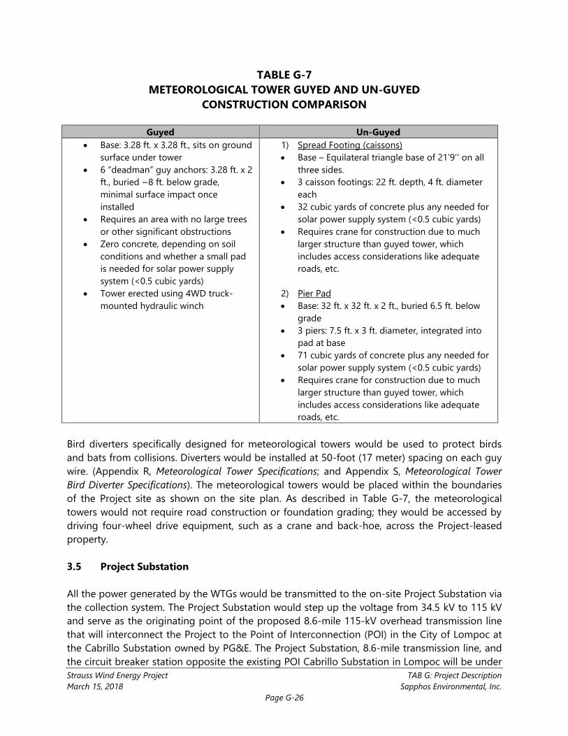
Strauss Wind Energy Project TAB G: Project Description
March 15, 2018 Sapphos Environmental, Inc.
Page G-26
TABLE G-7
METEOROLOGICAL TOWER GUYED AND UN-GUYED
CONSTRUCTION COMPARISON
Guyed Un-Guyed
Base: 3.28 ft. x 3.28 ft., sits on ground
surface under tower
6 “deadman” guy anchors: 3.28 ft. x 2
ft., buried ~8 ft. below grade,
minimal surface impact once
installed
Requires an area with no large trees
or other significant obstructions
Zero concrete, depending on soil
conditions and whether a small pad
is needed for solar power supply
system (<0.5 cubic yards)
Tower erected using 4WD truck-
mounted hydraulic winch
1) Spread Footing (caissons)
Base – Equilateral triangle base of 21’9’’ on all
three sides.
3 caisson footings: 22 ft. depth, 4 ft. diameter
each
32 cubic yards of concrete plus any needed for
solar power supply system (<0.5 cubic yards)
Requires crane for construction due to much
larger structure than guyed tower, which
includes access considerations like adequate
roads, etc.
2) Pier Pad
Base: 32 ft. x 32 ft. x 2 ft., buried 6.5 ft. below
grade
3 piers: 7.5 ft. x 3 ft. diameter, integrated into
pad at base
71 cubic yards of concrete plus any needed for
solar power supply system (<0.5 cubic yards)
Requires crane for construction due to much
larger structure than guyed tower, which
includes access considerations like adequate
roads, etc.
Bird diverters specifically designed for meteorological towers would be used to protect birds
and bats from collisions. Diverters would be installed at 50-foot (17 meter) spacing on each guy
wire. (Appendix R, Meteorological Tower Specifications; and Appendix S, Meteorological Tower
Bird Diverter Specifications). The meteorological towers would be placed within the boundaries
of the Project site as shown on the site plan. As described in Table G-7, the meteorological
towers would not require road construction or foundation grading; they would be accessed by
driving four-wheel drive equipment, such as a crane and back-hoe, across the Project-leased
property.
3.5 Project Substation
All the power generated by the WTGs would be transmitted to the on-site Project Substation via
the collection system. The Project Substation would step up the voltage from 34.5 kV to 115 kV
and serve as the originating point of the proposed 8.6-mile 115-kV overhead transmission line
that will interconnect the Project to the Point of Interconnection (POI) in the City of Lompoc at
the Cabrillo Substation owned by PG&E. The Project Substation, 8.6-mile transmission line, and
the circuit breaker station opposite the existing POI Cabrillo Substation in Lompoc will be under
Strauss Wind Energy Project TAB G: Project Description
March 15, 2018 Sapphos Environmental, Inc.
Page G-27
the ownership of the Applicant. The Project has obtained an interconnection agreement with
PG&E that was executed on July 27, 2017, to connect to their facilities located at the Cabrillo
Substation (Appendix P, PG&E Interconnection Agreement).9 The application was filed on March
31, 2016, and the Queue Number for the Applicant is 1320-WD. The Project has complied with
Federal Energy Regulatory Commission (FERC) Generator Interconnection Procedures. The
Applicant will operate as a wholesale power producer with 100 percent of the output to be
exported to the PG&E distribution system. The Point of Change of Ownership (PCO) will occur
on the Customer side of a PG&E T-Line disconnect switch at the POI1 location.
The Project will install and own one span of overhead line or approximately 200 ft of overhead
cable from the POI into an Applicant-owned circuit breaker station with metering equipment.
The Project will supply PG&E-approved high-voltage metering equipment and a metering
cabinet in the control building. PG&E will install and own only a meter in the Applicant-provided
cabinet. The height and bulk of required structures will not exceed those already within the
Cabrillo Substation (Figure G-9, Single Line Diagram of Point of Interconnection, Cabrillo
Substation; Figure G-10, Conceptual Site Plan Elevation).
The on-site Project Substation will be located entirely on the privately held land of a
participating Project landowner within the Project boundary. The Project Substation footprint
would disturb roughly 2.02 acres of land and be approximately 200 feet by 300 feet in
dimension. The footprint would be cleared and graded, and would include structural and
electrical equipment. Equipment will be installed on top of structural concrete forms, which will
be roughly 18 inches above rough grade. The substation perimeter would be entirely secured by
an 8-foot chain link fence topped with three-strand barbed wire, raked outward at a 45-degree
angle. A locked, double-swing gate would be installed in the fencing to provide access to the
Project Substation post-construction. No shrubbery, hedging, or landscaping around the
perimeter of the substation is contemplated. The entire footprint of the substation would be
finished with a graveled layer of clean, washed rock free of sands or organic material. This
rocked layer would act as a fire barrier and as step protection. In addition, spatial separation of
transformers and other design considerations would be incorporated in the design to prevent
the risk of fire. The substation will be meet or exceed IEEE-979 Substation Fire Protection
standards. Detection and extinguishing equipment would be installed in accordance with all
applicable code requirements. Project Substation signage as required by the NESC, OSHA, and
other applicable organizations would be provided. The substation will include standard low-
illumination, motion-triggered lighting (see Preliminary Site Plan Substation Site, in the Maps
tab). The highest structure of the substation would be the dead-end structure, which is a fully
self-supporting structure where the conductors of the transmission line mechanically terminates
to the substation. The Project Substation would be fitted with static poles that will create a
9 Pacific Gas and Electric. Understand PG&E distribution qualifications, Connect your project to our wholesale
distribution system. September 2017. Available at: https://www.pge.com/en_US/for-our-business-
partners/interconnection-renewables/energy-transmission-and-storage/wholesale-generator-
interconnection/wholesale-distribution-fast-track-interconnection-process.page

Strauss Wind Energy Project TAB G: Project Description
March 15, 2018 Sapphos Environmental, Inc.
Page G-28
shield to protect all of the equipment inside the Project Substation from lightning.
Static poles may or may not have overhead shield wires attached to enhance lightning
protection. The static poles would be approximately 60 feet above the substation grade. A
control building would be housed entirely within the Project Substation. The control building
contains switchboard panels, batteries, battery chargers, supervisory control, meters, and relays,
and provides all weather protection and security for the control equipment. It is estimated that
the control building would be 14 feet by 54 feet in dimension, pending release of the
conceptual site plan by the Applicant. The control building would be adequately ventilated to
prevent the accumulation of hydrogen gases from battery operation.
Project Substation lighting shall be designed so exterior light fixtures are hooded, with lights
directed downward or toward the area to be illuminated, and so that backscatter to the
nighttime sky is minimized.
The entire Project Substation would be enclosed with a chain link security fence. Following
construction, an inspection and commissioning test plan would be executed prior to the Project
Substation being energized.
3.6 Strauss Wind Energy Project Transmission Line
The transmission line would be constructed by the Applicant and permitted as part of the
Project through the Santa Barbara County CUP entitlement process as a result of its direct
connection to and interdependency with the Project.
Minor upgrades to PG&E’s Cabrillo Substation undertaken by PG&E are included in the
environmental analysis for the Project, but are expected to occur within the existing Cabrillo
Substation. It is expected that PG&E will provide the California Public Utilities Commission
(CPUC) with Notice of Intent to Construct through an advice letter filing, pursuant to General
Order (GO) 131-D, Section XI, Subsection B.4 of the Construction of Facilities that are exempt
from a Permit to Construct.
The applicant will be constructing the transmission line consistent with accepted industry
standards, protective measures, and established industry guidelines. These include the
recommended practices and procedures of the IEEE, standards for overhead line construction
consistent with CPUC General Order 95 (GO95), avian protection measures consistent with the
2012 Avian Power Line Interaction Committee Guidelines, electric magnetic field design
guidelines accepted for transmission design in California, and other applicable rules and
standards. Where feasible and consistent with CPUC GO 95, power lines will follow existing
distribution lines and/or will be consolidated with existing facilities.
All work on public streets and highways would be performed in a manner that interferes as little
as possible with the operations of other utilities and the convenience of the public, and causes
no unusually dangerous conditions to workmen, pedestrians, or others at any time.
Strauss Wind Energy Project TAB G: Project Description
March 15, 2018 Sapphos Environmental, Inc.
Page G-29
O&M activities for the power line would include frequent inspections to ensure that the system
is in good condition and would not create hazards.
Ongoing fire management and safety would include maintaining a 10-foot radial clearance of
flammable fuels (vegetation) around the base of each wood pole structure during fire season.
Under Public Resources Code, Section 4292, a minimum 15-foot clearance between vegetation
and conductors is required for safety and to minimize tree-related outages. Fast-growing trees
may be removed or vegetation trimmed back farther than the minimum required to achieve at
least 3 to 4 years of clearance before the next trim. In addition, the maintenance program would
also include removing dead, rotten, or diseased trees or vegetation that hang over or lean
toward the system, creating a falling hazard.
The transmission line would be constructed mostly of single wooden poles and a few double
wooden poles. Single steel poles would be needed at a few engineered angle points; the
number of steel poles would be determined as part of final transmission line design. The poles
would be up to approximately 75 feet in height and would be placed from 64 to 1,280 feet (380
feet average) apart based on the terrain and alignment. Assuming as a worst-case scenario that
poles were placed every 250 feet, as many as 115 poles would be required. In some locations,
engineered structures with concrete foundations might be used to support the conductors. The
exact number of poles and their sizes, types, and spacing would be determined as part of final
design engineering. The Applicant anticipates acquiring easements ranging from 50 to 100 feet
wide, depending on design, span length, and terrain.
The transmission line route is described in Section 2.1.1. In order to ensure reliability, the Project
transmission line would use new poles, and would run parallel to existing power lines. It is
assumed that no currently existing power poles would be used.
Strauss Wind Energy Project TAB G: Project Description
March 15, 2018 Sapphos Environmental, Inc.
Page G-30
4.0 FACILITY CONSTRUCTION
4.1 Construction Phasing
The Project would be constructed in one phase in order to achieve the full 102 MW generating
capacity of the Project. Construction would begin as soon as the required Project approvals,
including the conditional use permit, grading, building, and other permits are obtained from the
County and other responsible agencies (see Section 9 of this Project Description). Construction
would be anticipated to start by the first quarter of 2019 and continue for approximately 10
months ending by the fourth quarter of 2019. The commercial operation date is estimated to be
the fourth quarter of 2019. Construction work to interconnect the Project would occur during
the specified time frame assuming no significant environmental issues are identified.
4.2 General Procedures
Normally, construction would occur during daylight hours, Monday through Saturday; however,
some activities could require extended hours because of scheduling constraints or other time-
sensitive matters, or to maintain structural integrity of concrete placement. Construction would
typically proceed according to the following flow of work:
Grading of field construction office, laydown area, and Project Substation
Construction of site roads, turnaround areas, and crane pads at each WTG
location
Construction of the WTG tower foundations, transformer pads, and
meteorological towers
Installation of the electrical collection system (underground and overhead lines)
Assembly and erection of the WTGs
Construction and installation of the Project Substation and O&M building
Commissioning and energizing the Project
4.3 Design and Engineering Process for Operations and Maintenance Site, Laydown
Area and Substation Sites
Initially, a topographical survey will be performed for all sites, which include data collection for
all utilities, existing conditions, and water courses. Record data for any existing improvements,
including underground utilities will be researched and reflected on the base map.
Strauss Wind Energy Project TAB G: Project Description
March 15, 2018 Sapphos Environmental, Inc.
Page G-31
Although each site is not shown to be within a designated flood plain, there are ephemeral
watercourses nearby. Hydrology to determine storm water flows within these watercourses will
be performed, in addition to hydraulic analysis to determine the maximum water surface
elevation. Building pad elevations for habitable structures and mechanical equipment will be set
with at least one foot of freeboard above the maximum water surface for the 100-year storm
event. Similarly, pad elevation for any areas that could store potentially hazardous materials, will
be elevated with the same freeboard.
The grading and site design will also mitigate storm water flows, both from offsite, and that
which is generated onsite. Offsite storm water flows must be received and discharged with as
little change as possible to the character of said flow. This includes avoiding concentrating,
increasing or polluting storm water flow. Storm water flows generated on-site will be discharged
devoid of pollutants and without an increase to the historical runoff. Consideration should be
given to implementing bio-retention areas.
Site engineering will also include soil borings to evaluate soils and groundwater conditions. This
data is used to specify preparation of earthwork under building foundations, pavement
structural section design, management of sub-surface water, and design of the septic system for
sewage disposal. Septic systems will be designed to avoid contact with ground water and
watercourses.
Historical information will be used to design and develop a well for potable use. Domestic and
Fire Protection needs will be the basis of engineering design of the water system, and water
storage requirements.
Site engineering must meet all federal, state and local codes, including setbacks, driveway
ingress and egress, sight distances onto public streets, landscaping, parking, lighting, and the
Americans with Disabilities Act.
Other site improvements will include security fencing and gates, security systems, lighting, dry
utility connections, asphalt or Portland cement concrete for parking areas.
4.4 Construction Traffic
All Project materials would be brought to the site via Highway 101 to Highway 246 from the
north or via Highway 101 to SR-1 from the south.
Strauss Wind Energy Project TAB G: Project Description
March 15, 2018 Sapphos Environmental, Inc.
Page G-32
The Applicant evaluated San Miguelito Road in February 2016, March 2017, and again in
October 2017 with the Project’s wind turbine manufacturer, transportation company, and project
engineers to confirm the feasibility of transportation of project components to the site. 10
While
some road widening and temporary improvements would be necessary along the route (see
Appendix I, Transportation Study, for additional details on improvements to San Miguelito Road),
San Miguelito Road provides a feasible transportation route for the project.
The Project would employ 50 to 100 workers at the site during the peak of construction. It is
anticipated that a minimum of 80 percent of the workers would live or stay in the Lompoc area.
Assuming 100 workers and 1.1 persons per vehicle, approximately 91 worker vehicles, or 182
one-way vehicle trips, would be required per day (standard carpool factor). The most significant
construction activities are expected to occur over a 6-month period, with a few months expected
for construction mobilization and demobilization, for an estimated 10-month total construction
schedule. The estimated numbers and types of construction equipment that would be used
during each phase of construction are summarized in Table G-8 (Construction Equipment Count).
All equipment would be operated with diesel fuel.
10
ATS Projects Wind Energy Services. February 24, 2017. Strauss Wind Project Review.

Strauss Wind Energy Project TAB G: Project Description
March 15, 2018 Sapphos Environmental, Inc.
Page G-33
TABLE G-8
CONSTRUCTION EQUIPMENT COUNT
Constructio
n Phase Excavato
r
D-9
Bu
lld
ozer
D-6
Bu
lld
ozer
Du
mp
Tru
ck
Co
mp
acto
r
Back
ho
e
14
-H G
rad
er
Gra
dall
Wate
r T
ruck
Fro
nt
En
d L
oa
der
Scra
per
Art
icu
late
d D
um
p T
ruck
Ro
ck
Cru
sher
Co
ncre
te T
ruck
s
CM
P R
oll
er
Tele
han
dle
r
Tre
nch
er
Pad
din
g M
ach
ine
Lin
e T
ruck
12
0-T
Cra
ne
90
-T C
ran
e
Pri
me M
ove
r
Cra
wle
r C
ran
e
Pic
ku
p T
ruck
Du
mp
Tru
ck
Gen
era
tor
To
tal
Access Roads 1 1 3 1 1 1 1 1 10
Site Roads 1 2 1 3 2 1 1 1 7 1 2 2 1 25
Foundations 1 1 6 1 1 10
Collection
System
1 1 1 1 1 5
WTG Deliveries 1 1 2 1 5
WTG Erection 1 1 2 1 5
Substation 1 1 1 1 1 1 1 1 8
T-Line 3 3
Testing &
Commissioning
6 6
Reclamation 1 1 1 3
Office Area 1 1
Total 4 2 4 7 3 5 3 2 8 2 2 2 1 7 1 4 1 1 5 2 5 1 1 6 1 1 81
Note: * Estimated construction equipment includes O&M building and meteorological tower construction.
Strauss Wind Energy Project TAB G: Project Description
March 15, 2018 Sapphos Environmental, Inc.
Page G-34
4.5 Field Survey and Construction Specifications
A civil engineering site survey has been performed to stake out the planned location of the
WTGs, site roads, and electrical lines. Using data acquired from the geotechnical evaluation
prepared by Ninyo & Moore in 2011 and updated in 2017,11
the Applicant will establish a set of
site-specific construction specifications for each WTG and other components of the Project (see
Appendix E, Geology and Soils Technical Report). In order to avoid impacts to sensitive species
and cultural resources, any geotechnical drilling within 100 feet of all surface-disturbing
activities would require biological and cultural resources monitoring by qualified biologists and
archaeologists.
Biological monitoring would be based on protocols established by the USFWS, California
Department of Fish and Wildlife (CDFW), and the California Native Plant Society (CNPS).
Biological monitors would provide a daily monitoring report to be included in a Daily Field
Report. To adhere to regulatory standards, on-site surveys by qualified archaeologists are
necessary where surveys have not been conducted previously. Archaeologists would complete
daily survey logs and reports, and update Project information as appropriate. When
geotechnical drilling has been completed, the site would be restored to original grade and
seeded with an approved native seed mix.
4.6 Site Preparation and Road Construction
Site activities would begin with construction of site access entryways from San Miguelito Road,
rough grading of access roads, leveling of the construction laydown and site office parking area,
and installation of six to eight temporary site office trailers with temporary power at the
intersection of San Miguelito Road and Sudden Road. All grading would be done in accordance
with a formal Stormwater Pollution Prevention Plan (SWPPP) for the Project.
Access roads would be gravel surfaced unless extremely steep slopes necessitate paving. When
rough grade is achieved, base rock would be trucked in, spread, and compacted to create a road
base. Capping rock would then be spread over the road base and roll-compacted to finished
grade. The width of construction access roads will vary between 22 to 40 feet to accommodate
roadway cut and fill, and necessary equipment turning radii and turn-outs. At completion of
heavy construction, the road would be regraded to a width of 16 feet for service as a
maintenance road. A final pass would be made with the grading equipment to level the road
surfaces, and more capping rock would be spread and compacted in areas where needed. In
some very steep areas, the road might be paved. Water bars, similar to speed bumps, would be
cut into the roads in areas where needed, to allow for natural drainage of water over the road
surface and to prevent road washout.
11
Ninyo & Moore. (2011) April 27, 2017. Geotechnical Evaluation, Strauss Wind Energy Project, Santa Barbara County,
CA. See Appendix E.
Strauss Wind Energy Project TAB G: Project Description
March 15, 2018 Sapphos Environmental, Inc.
Page G-35
V ditches and culverts would be installed, where necessary, to handle excess drainage water. All
road work would be performed under final approved grading, erosion control, and stormwater
quality management plans.
Excess excavated soil and rock would be disposed of onsite at approved disposal areas, such as
eroded gullies and ravines. Larger excavated rocks also would be disposed of at approved sites
or crushed and re-used onsite as backfill or roadway material. Project road construction would
involve the use of several pieces of heavy machinery, including bulldozers, track-hoe excavators,
front-end loaders, dump trucks, motor graders, water trucks, and rollers for compaction.
Stormwater measures, such as hay bales and diversion ditches, would control stormwater runoff
during construction. Access points from public roads would have locked gates, as agreed upon
with the landowners
4.7 Equipment and Water Requirements
Heavy equipment would be needed to clear the sites, build roads and WTG foundations, haul
and lift materials, and pull the power line. After roads are opened and foundations built, cranes
and trucks would move in to haul and lift the WTG parts into position for assembly. An average
of 222 truck trips per month would occur during Months 5 through 7 of the construction period,
as shown in Table G-9 (Estimated Construction Truck Trips). These trucks would haul WTG parts
to the Project site. Each truck would have a gross weight ranging between 30,000 and 180,000
pounds. The trucks would have many axles to spread the load on streets and roads and be in
compliance with the transportation permits issued by the State of California. The trucks would
enter the area from Lompoc using established truck routes and proceed to designated areas for
unloading. Road material and water would be hauled from local sources.
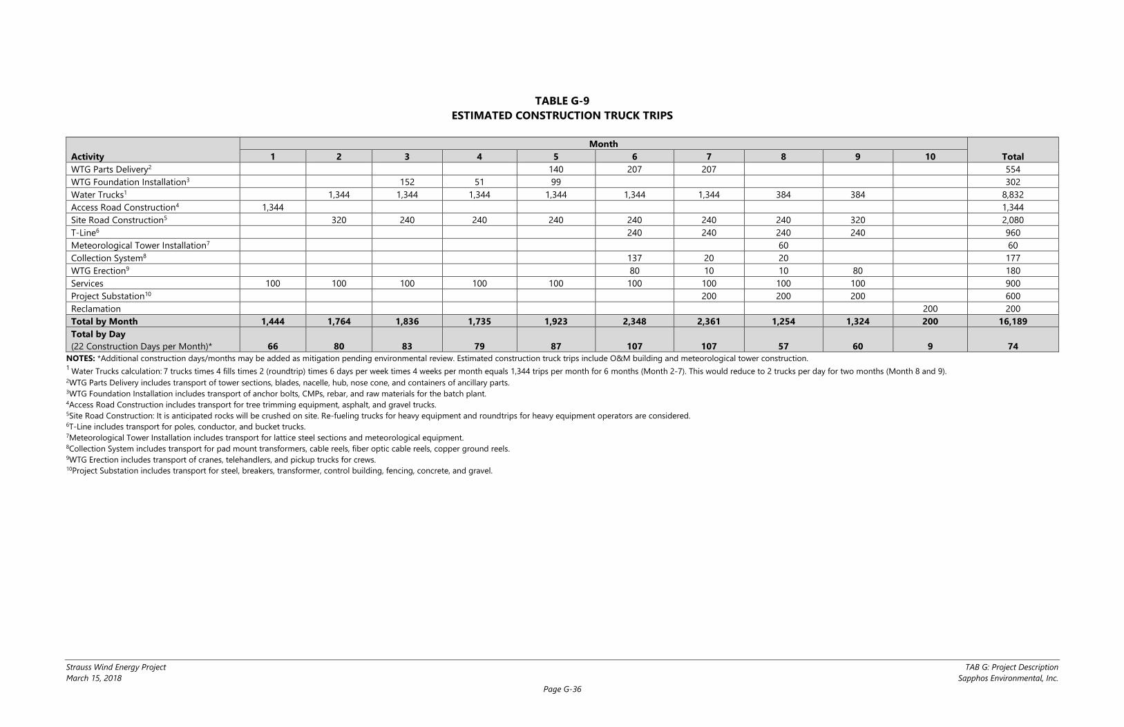
Strauss Wind Energy Project TAB G: Project Description
March 15, 2018 Sapphos Environmental, Inc.
Page G-36
TABLE G-9
ESTIMATED CONSTRUCTION TRUCK TRIPS
Activity
Month
Total 1 2 3 4 5 6 7 8 9 10
WTG Parts Delivery2
140 207 207
554
WTG Foundation Installation3
152 51 99
302
Water Trucks1
1,344 1,344 1,344 1,344 1,344 1,344 384 384
8,832
Access Road Construction4 1,344
1,344
Site Road Construction5
320 240 240 240 240 240 240 320
2,080
T-Line6
240 240 240 240
960
Meteorological Tower Installation7
60
60
Collection System8
137 20 20
177
WTG Erection9
80 10 10 80
180
Services 100 100 100 100 100 100 100 100 100
900
Project Substation10
200 200 200
600
Reclamation
200 200
Total by Month 1,444 1,764 1,836 1,735 1,923 2,348 2,361 1,254 1,324 200 16,189
Total by Day
(22 Construction Days per Month)* 66 80 83 79 87 107 107 57 60 9 74
NOTES: *Additional construction days/months may be added as mitigation pending environmental review. Estimated construction truck trips include O&M building and meteorological tower construction. 1
Water Trucks calculation: 7 trucks times 4 fills times 2 (roundtrip) times 6 days per week times 4 weeks per month equals 1,344 trips per month for 6 months (Month 2-7). This would reduce to 2 trucks per day for two months (Month 8 and 9). 2WTG Parts Delivery includes transport of tower sections, blades, nacelle, hub, nose cone, and containers of ancillary parts. 3WTG Foundation Installation includes transport of anchor bolts, CMPs, rebar, and raw materials for the batch plant. 4Access Road Construction includes transport for tree trimming equipment, asphalt, and gravel trucks. 5Site Road Construction: It is anticipated rocks will be crushed on site. Re-fueling trucks for heavy equipment and roundtrips for heavy equipment operators are considered. 6T-Line includes transport for poles, conductor, and bucket trucks. 7Meteorological Tower Installation includes transport for lattice steel sections and meteorological equipment. 8Collection System includes transport for pad mount transformers, cable reels, fiber optic cable reels, copper ground reels. 9WTG Erection includes transport of cranes, telehandlers, and pickup trucks for crews. 10Project Substation includes transport for steel, breakers, transformer, control building, fencing, concrete, and gravel.
Strauss Wind Energy Project TAB G: Project Description
March 15, 2018 Sapphos Environmental, Inc.
Page G-37
A portable “wet mix” concrete batch plant would be set up to meet construction needs at the
staging area located north of the intersection of San Miguelito and Sudden Road. The portable
batch plant would consist of equipment that combines various ingredients to form concrete,
including water, air, admixtures, sand, aggregate, and cement (Figure G-11, Portable Concrete
Batch Plant). Foundations for each WTG would require up to several hundred yards of concrete.
The batch plant would be mobilized using approximately five trucks. In addition, the batch plant
would require approximately seven truckloads of material per foundation to operate the batch
plant. Foundations for each WTG would require several hundred yards of concrete and slurry,
which must generally be placed within 45 minutes of being made or “batched.” The onsite batch
plant would reduce the travel time for the mixer trucks and the number of trips over public
roads. Water would be trucked in for the concrete batch plant and would be obtained from the
Lompoc Regional Wastewater Reclamation Plant (LRWRP) at 1801 W. Central Ave. Lompoc, CA
93436. Water use associated with the batch plant is approximately 13,500 gallons per day. The
Applicant has received a “Can and Will Serve” Letter from the City of Lompoc for up to 62,000
gallons per day of recycled water for the Project (Appendix U, City of Lompoc Can and Will Serve
Letter). The batch plant would only be operated during working hours on days that foundation
pours are scheduled. Approximately seven concrete trucks would travel between the batch plant
and the foundation location using site roads for most of the time. Upon completion of the
foundation pours, the batch plant would be disassembled and trucked offsite, along with any
remaining material that was stored to batch the concrete. After concrete is poured, the chutes of
ready mixed concrete trucks and hoppers of concrete pump trucks must be washed out to
remove the remaining concrete before it hardens. All concrete washouts would occur using
washout pits or containers. All hardened concrete contained in the pits and/or containers would
be hauled offsite and disposed of accordingly.
Reclaimed water from the LRWRP would also be trucked in as needed for dust control during
construction. As many as 9,000 gallons of water (5 to 6 truck trips) could be required on dry,
dusty days. The amount of water available through the Can and Will Serve Letter far exceeds the
total water usage needs on the Project.
Heavy equipment would be needed to clear the sites, build roads and WTG foundations, haul
and lift materials, and pull power line. After roads were opened and foundations built, cranes
and trucks would move in to haul and lift the WTG parts into position for assembly. An average
of 1,619 truck trips per month during the approximately 10-month construction period as shown
in Table G-9 and Table G-10 (Project Construction Schedule) would haul WTG parts to the Project
site, each with a gross weight ranging between 30,000 and 180,000 pounds. The trucks would
have many axles to spread the load on streets and roads. The trucks would enter the area from
Lompoc using established truck routes and proceed to designated areas for unloading. Road
material, concrete, and water would be hauled from local sources.

Strauss Wind Energy Project TAB G: Project Description
March 15, 2018 Sapphos Environmental, Inc.
Page G-38
TABLE G-10
PROJECT CONSTRUCTION SCHEDULE
Project Construction Element
Month
1 2 3 4 5 6 7 8 9 10
Access Roads
Site Roads
Foundations
Collection System
Meteorological Towers
WTG Deliveries
WTG Erection
Substation
O&M Building
T-Line
Testing & Commissioning
Reclamation
NOTE: Construction during the rainy season will be conducted in accordance with SWPPP and erosion control
measures. In some cases conditions may necessity a delay in activities at specific locations due to impassible terrain,
potential erosion, or other environmental constraints.
The estimated 8,832 water truck trips in Table G-9 are based on 7 water trucks operating daily,
each cycling 4 times per day. After road construction has been completed, 2 daily water trucks
will be required. Truck trips totaling 1,344 per month six month 7 (trucks)*4 (fills)*2 (round
trips)*6 (days per week)*4 (weeks per month), then reducing down to 2 trucks per day for 2
months. During road construction, water would be used for dust control and compaction. Once
road construction has been completed, it is assumed that 2 of the trucks will continue with dust
control operations to spray down roads in areas of active construction. It is assumed water
trucks would be operating 6 days per week.
A batch plant would be used at the site to supply concrete for the WTG foundations. The
running of the concrete from the batch plant to the WTG foundations is not considered in the
calculation in Table G-9, since the batch plant will be located within the Project boundary. The
batch plant will be mobilized using 3 semi-trucks. Each WTG foundation uses about 3,300
gallons of water. Water may be hauled in using a 10,000-gallon trailer. This would add 10 more
truck loads times 2 (roundtrip) to Table G-9.
The batch plant will be mobilized and demobilized using 3 truckloads times 2 (roundtrip) for a
total of 6 truckloads. Raw materials including Portland cement, aggregate, admixtures, etc.
would need to be delivered to “feed” the batch plant. It is assumed that 4 truckloads of raw
material per foundation would be needed, at a rate of 3 installed foundations per week times 4
weeks per month times 2 (roundtrip), for a total of 96 truckloads. Furthermore, anchor bolts,
corrugated metal pipes (CMP) and reinforcing steel would also need to be delivered for each
wind turbine foundation. Multiple sets can be delivered on a truckload. Typically, anchor bolts
for 1.5-foundations-worth can be delivered on a single truckload. For 30 foundations, the anchor

Strauss Wind Energy Project TAB G: Project Description
March 15, 2018 Sapphos Environmental, Inc.
Page G-39
bolts would require 20 trucks times 2 (roundtrip) for a total of 40 truckloads. Similarly, CMP
material for 6 foundations can be delivered on a single truckload so for 30 foundations, there
would need to be 5 trucks times 2 (roundtrip) for a total of 10 truckloads. In total, the batch
plant would require 152 truckloads.
Each WTG foundation uses about 3,300 gallons of water. Water may be hauled in using a
10,000-gallon trailer. This would add 10 more truck loads times 2 (Roundtrip) to Table G-9. The
Applicant has received a can and will serve letter from the City of Lompoc for up to 62,000
gallons per day of recycled water for trucked uses for the Project (Appendix U, City of Lompoc
Can and Will Serve Letter).
4.8 Disturbed Areas
The area of temporary and permanent land disturbance was calculated based on the conceptual
grading plan at 229.82 acres for the Project Area and the Transmission Line Access Roads (Table
G-11, Estimated Temporary and Permanent Land Disturbance). Based on the evaluation of the
conceptual grading plan, it is anticipated that the cut and fill will be balanced onsite (Table G-12,
Estimated Earthwork). The area of land disturbance is the same as the area shown in the
Preliminary Grading Plan (in the Maps tab). These areas include turbine pads, access roads,
internal collection, substation, staging area, O&M facility, external transmission line, and access
roads to the pole locations of the external transmission line. A 10-foot buffer has been added to
the preliminary grading disturbance area to account for the potential disturbance outside of the
grading design. It is anticipated that all temporary and permanent impacts to soil and
vegetation would be limited to the areas delineated in the conceptual grading plan and the 10-
foot buffer area.
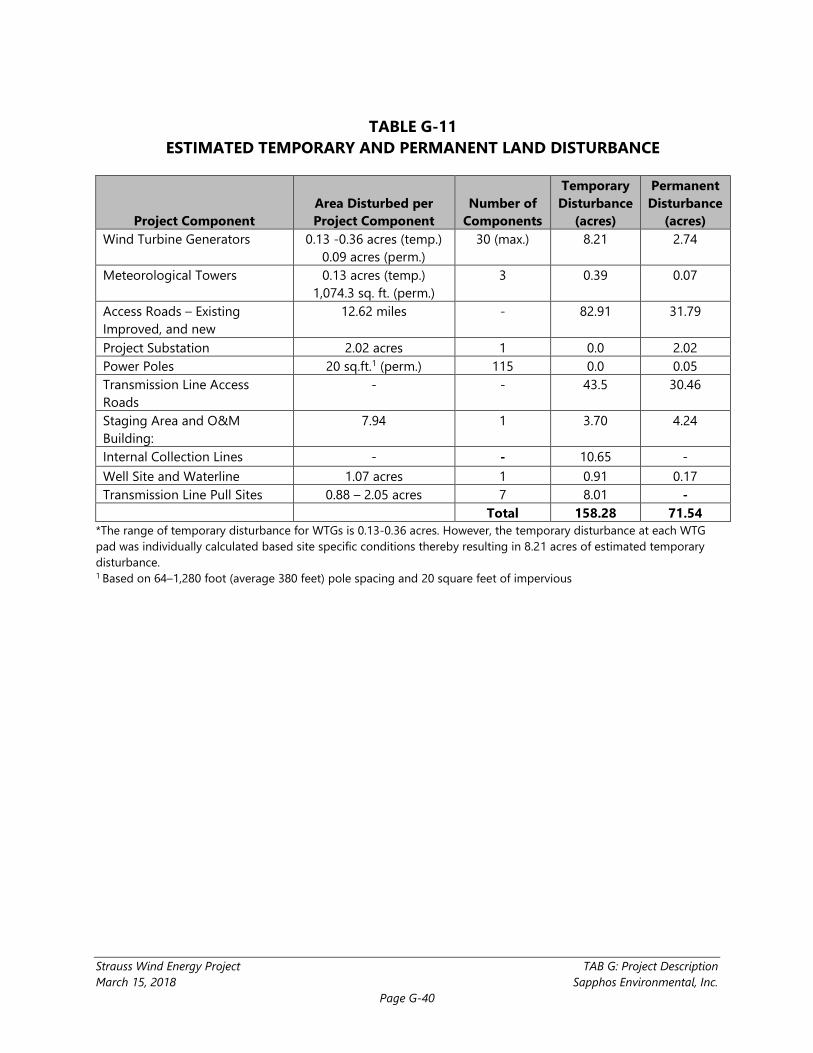
Strauss Wind Energy Project TAB G: Project Description
March 15, 2018 Sapphos Environmental, Inc.
Page G-40
TABLE G-11
ESTIMATED TEMPORARY AND PERMANENT LAND DISTURBANCE
Project Component
Area Disturbed per
Project Component
Number of
Components
Temporary
Disturbance
(acres)
Permanent
Disturbance
(acres)
Wind Turbine Generators 0.13 -0.36 acres (temp.)
0.09 acres (perm.)
30 (max.) 8.21
2.74
Meteorological Towers 0.13 acres (temp.)
1,074.3 sq. ft. (perm.)
3 0.39 0.07
Access Roads – Existing
Improved, and new
12.62 miles - 82.91 31.79
Project Substation 2.02 acres 1 0.0 2.02
Power Poles 20 sq.ft.1 (perm.) 115 0.0 0.05
Transmission Line Access
Roads
- - 43.5 30.46
Staging Area and O&M
Building:
7.94 1 3.70 4.24
Internal Collection Lines - - 10.65 -
Well Site and Waterline 1.07 acres 1 0.91 0.17
Transmission Line Pull Sites 0.88 – 2.05 acres 7 8.01 -
Total 158.28 71.54
*The range of temporary disturbance for WTGs is 0.13-0.36 acres. However, the temporary disturbance at each WTG
pad was individually calculated based site specific conditions thereby resulting in 8.21 acres of estimated temporary
disturbance. 1 Based on 64–1,280 foot (average 380 feet) pole spacing and 20 square feet of impervious
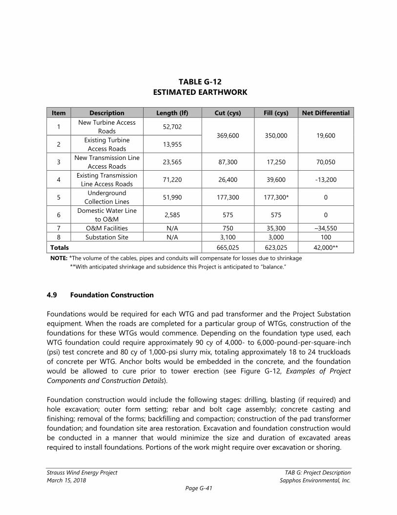
Strauss Wind Energy Project TAB G: Project Description
March 15, 2018 Sapphos Environmental, Inc.
Page G-41
TABLE G-12
ESTIMATED EARTHWORK
Item Description Length (lf) Cut (cys) Fill (cys) Net Differential
1 New Turbine Access
Roads 52,702
369,600 350,000 19,600
2 Existing Turbine
Access Roads 13,955
3 New Transmission Line
Access Roads 23,565 87,300 17,250 70,050
4 Existing Transmission
Line Access Roads 71,220 26,400 39,600 -13,200
5 Underground
Collection Lines 51,990 177,300 177,300* 0
6 Domestic Water Line
to O&M 2,585 575 575 0
7 O&M Facilities N/A 750 35,300 –34,550
8 Substation Site N/A 3,100 3,000 100
Totals 665,025 623,025 42,000**
NOTE: *The volume of the cables, pipes and conduits will compensate for losses due to shrinkage **With anticipated shrinkage and subsidence this Project is anticipated to “balance.”
4.9 Foundation Construction
Foundations would be required for each WTG and pad transformer and the Project Substation
equipment. When the roads are completed for a particular group of WTGs, construction of the
foundations for these WTGs would commence. Depending on the foundation type used, each
WTG foundation could require approximately 90 cy of 4,000- to 6,000-pound-per-square-inch
(psi) test concrete and 80 cy of 1,000-psi slurry mix, totaling approximately 18 to 24 truckloads
of concrete per WTG. Anchor bolts would be embedded in the concrete, and the foundation
would be allowed to cure prior to tower erection (see Figure G-12, Examples of Project
Components and Construction Details).
Foundation construction would include the following stages: drilling, blasting (if required) and
hole excavation; outer form setting; rebar and bolt cage assembly; concrete casting and
finishing; removal of the forms; backfilling and compaction; construction of the pad transformer
foundation; and foundation site area restoration. Excavation and foundation construction would
be conducted in a manner that would minimize the size and duration of excavated areas
required to install foundations. Portions of the work might require over excavation or shoring.
Strauss Wind Energy Project TAB G: Project Description
March 15, 2018 Sapphos Environmental, Inc.
Page G-42
Backfilling would be completed immediately after approval by the engineer’s field inspectors.
Onsite excavated materials would be used for backfill where possible. An estimated 125 cy of
excavated soil would remain from each WTG. The excess soil not used as backfill for the
foundations would be used to level out low spots on the crane pads and roads to make them
consistent with the surrounding grade, and exposed soil would be reseeded with a designated
mix of grasses around the edges of the disturbed areas. Larger rocks would be disposed of
offsite, or crushed into smaller rocks for use as backfill or road material. Excess soil not used
around the WTG sites would be disposed of in eroded areas onsite.
4.10 Internal Electrical Collection System
Although the majority of the collection system will be placed underground within the proposed
roads, Approximately 2.21 miles of underground collection lines will be outside of the proposed
road improvements, and approximately 1.0 mile of overhead collection lines is proposed
between the substation site and WTG 23, and between WTG 22 and 24. The overhead line
between WTG 22 and WTG 24 avoids an underground alternative that would result in significant
additional grading in the Coastal Zone. This overhead span across the existing steep terrain
would be approximately 1,280 feet and would require two poles placed within the disturbance
footprint of WTG 22 and WTG 24, respectively. Access to these pole locations would occur on
the access roads designed for WTG 22 and WTG 24. No additional roads would be required at
this location. The overhead line between the substation site and WTG 23 would be co-located
on a portion of the project transmission line that ultimately exits the site to the POI at the
Cabrillo Substation in Lompoc. This section of collector line would not result in any additional
impacts above those assumed for the transmission line in this location. The overhead collector
system will be designed to avoid avian electrocution and collision mortality using the APLIC
guidelines.12
Wherever feasible and practical, the layout of the internal electrical collection system has been
aligned with roads; however, in some instances it is more efficient to provide more direct
connections between turbines via underground and overhead facilities (see Site Plan, in the
Maps tab). The total area of disturbance for the Internal Electrical Collection System, located
outside the roads, would be 10.62 acres, with cut and fill of 177,300 cubic yards of grading to be
balanced on-site (Tables G-11 and G-12). After the roads, WTG foundations, and transformer
pads are completed for a particular row of WTGs, underground cables would be installed along
that road section. Trenches would be cut to the required depth. Cables would be laid in the
trenches, surrounded with a cushion of clean fill, inspected, and the trenches backfilled.
Shallower trenches might be required where solid rock is encountered. The 34.5-kV cables
would be connected to the WTG pad mounted transformers, and low-voltage wiring between
the transformers and the bus cabinet inside the WTG towers would be completed, inspected,
12
Edison Electric Institute and USFWS. Avian Protection Plan Guidelines. April 2005. Available at:
http://www.aplic.org/uploads/files/2634/APPguidelines_final-draft_Aprl2005.pdf
Strauss Wind Energy Project TAB G: Project Description
March 15, 2018 Sapphos Environmental, Inc.
Page G-43
and tested.
To construct the overhead collector system, holes would be drilled and the poles erected with a
small crane or boom truck. The poles would be set in place using concrete or compacted clean
fill, according to the engineer’s specifications. The overhead lines would be connected to the
underground cables at each end through a fused disconnect switch, which would ensure
personnel safety by breaking the electrical connection in the event of a power surge.
4.11 Project Substation
The Project Substation and interconnection facilities construction would involve several stages
of work, including grading of the Project Substation area; installation of a grounding mat;
construction of several foundations for the transformers, power circuit breakers, and structures;
erection and placement of the steel work and all outdoor equipment; and electrical work for all
of the required terminations. The entire Project Substation would be enclosed with a chain link
security fence. The highest structure of the substation would be the dead-end structure, which is
a fully self-supporting structure where the conductors of the transmission line mechanically
terminates to the substation. The Project Substation would be fitted with static poles that create
a shield to protect all of the equipment inside the Project Substation from lightning. Static poles
may or may not have overhead shield wires attached to enhance lightning protection. The static
poles would be approximately 60 feet above the substation grade. A control building would be
housed entirely within the Project Substation. The control building contains switchboard panels,
batteries, battery chargers, supervisory control, meters, and relays, and provides all weather
protection and security for the control equipment. It is estimated that the control building would
be 14 feet by 54 feet in dimension, pending release of the conceptual site plan by the Applicant.
The control building would be adequately ventilated to prevent the accumulation of hydrogen
gases from battery operation. Following construction, an inspection and commissioning test
plan would be executed prior to the Project Substation being energized.
4.12 Wind Turbine Generators
The WTG components would be delivered to the site via transport trucks in multiple sections;
the main components would be off-loaded at the individual WTG sites or possibly staged at the
site before transport to the final location. After setting the WTG electrical bus cabinet and
ground control panels on the foundation, the tower would be erected by crane in sections.
Tower construction would be followed by hoisting and installation of the nacelle; assembly,
hoisting, and installation of the rotor; connection and termination of internal cables; and
inspection and testing of the electrical system.
Strauss Wind Energy Project TAB G: Project Description
March 15, 2018 Sapphos Environmental, Inc.
Page G-44
The rotors for the GE 1.79-100 MW WTGs will be constructed on the ground at the WTG
location, connecting the three blades to a hub. The hub rests on a stand, which is removed prior
to erection of the assembled rotor. Each blade will be attached to the hub utilizing the main
erection crane, which can lift each blade with a spreader bar attachment thereby avoiding the
need for a tandem pick of the blade. The assembled rotor will sit approximately 4 ft above the
ground on the hub stand, allowing the blades to remain suspended above the ground within the
construction staging area, and in any areas immediately surrounding the staging area. Therefore,
there is no grubbing or grading required beyond the designated limits of the construction
stating area designated for the assembly of the WTG. In cases where the blades overhang, either
down-slope or upslope areas, the assembled rotor orientation can change to accommodate the
contours. For example, blade number 1 can move from the 12 o’clock position to another
position to accommodate the contours. As a result, grubbing and grading would be limited to
the designated areas of permanent and temporary disturbance for each WTG.
The rotors for the GE 3.8-130 MW WTGs will be constructed with a single blade lift while
suspended from the crane. When the rotor is ready to be attached to the nacelle, the main crane
attaches to the hub while a support crane (typically a rough-terrain “RT” style hydraulic crane)
attaches to one of the blades. The RT tailing crane does not require a crane pad to be built, and
is mobilized within the disturbed area where the other turbine equipment (towers, blades, etc.)
had been staged around the foundation prior to erection. The two cranes work in tandem until
the rotor is rotated 90-degrees. The tailing crane then detaches and the main crane completes
the installation of the rotor to the nacelle main shaft, again, from its location on the crane pad.
(Appendix V, WTG Construction Sequence). All grading or grubbing would occur within
designated areas of permanent and temporary disturbance for each WTG.
4.13 Hazardous Materials
Potential hazardous materials expected to be used or produced during implementation of the
Project include fuels (gasoline and diesel), lubricants and motor oil, and combustion emissions.
Toxic Air Contaminants (TACS) such as benzene would be emitted at trace levels as byproducts
of the combustion of diesel and gasoline.
Gearboxes would contain oil that would not be routinely renewed. Yaw system bearings and
control gears would be greased, and the hydraulic oil checked and renewed approximately every
5 years. The cooling system would contain water and ethylene glycol that would be tested
annually. All testing or replacement would be performed up tower; therefore, all fluids, including
those from accidental spills, would be contained within the nacelle and the tower structures.
Additionally, the WTG models that would be installed for the Project would be equipped with
leak-proof gaskets.
Strauss Wind Energy Project TAB G: Project Description
March 15, 2018 Sapphos Environmental, Inc.
Page G-45
However, these chemicals would need to be transported to the Project site. To minimize the
potential for harmful effects to people or the environment, stored chemicals would be held in
onsite tanks or drums equipped with secondary containment areas to prevent runoff. No
extremely hazardous materials are currently anticipated to be produced, used, stored,
transported, or disposed of as a result of the Project.
If cleaning chemicals or detergents were used, they would generally be biodegradable and
stored off-site in sealed containers. Oils that might be needed for normal maintenance would be
stored in drums or smaller sealed containers off-site and transported to the WTG when needed.
Construction equipment and trucks would be properly maintained to minimize leaks of motor
oils, hydraulic fluids, and fuels. Major vehicle maintenance would be performed offsite at an
appropriate facility. Gasoline- and diesel-powered vehicles and equipment would be refueled
onsite at designated locations by a mobile fuel service truck.
A supply of chemicals would be stored at a facility in close proximity to the site to allow and
facilitate maintenance and repair. Chemicals would be stored in tanks or drums located within
secondary containment areas at the designated storage facility. Use of extremely hazardous
materials is not anticipated. Storage and use of hazardous materials would be subject to a
Hazardous Materials Management Plan and a Spill Prevention Control and Countermeasures
Plan (SPCC) approved by the SBCFD, which would include safe handling practices from the
Material Safety Data Sheets (MSDS).
4.14 Startup
Each completed WTG would be inspected and checked for mechanical, electrical, and control
functions in accordance with the manufacturer’s specifications before being released for startup
testing. A series of startup procedures would then be performed by the manufacturer’s
technicians; this process would require approximately 8 to 16 hours per WTG. Final testing
would involve mechanical, electrical, control, and communications inspections and tests to
ensure that all systems are working properly.
After the WTGs have been commissioned and are producing power, a period of acceptance
testing would begin to ensure that the WTGs are performing according to the agreed-upon
parameters. During this time, the power produced would be fed into the utility grid. Electrical
tests on the transformers, power lines, and Project Substation would be performed by qualified
engineers, electricians, and test personnel to ensure that electrical equipment is operating within
tolerances and that the equipment has been installed in accordance with design specifications,
standards and requirements by PG&E and CAISO.
Strauss Wind Energy Project TAB G: Project Description
March 15, 2018 Sapphos Environmental, Inc.
Page G-46
4.15 Site Restoration and Landscape Plan
Site restoration and cleanup would include reseeding of specifically identified areas subject to
temporary disturbance during the first suitable weather conditions after the heavy construction
activities have been completed, or as per the Project’s restoration and revegetation plan.
Temporary disturbance areas around WTG sites would be reseeded with native grasses to allow
the current use of the property to continue to the maximum extent practicable while
maintaining adequate access to all WTGs. Temporary disturbance on the shoulder areas of
access roads (new and improved) would also be reseeded. The 2-acre fenced substation area
would be covered with crushed rock; no other landscaping is planned because of this area’s
interior location within the Project site.
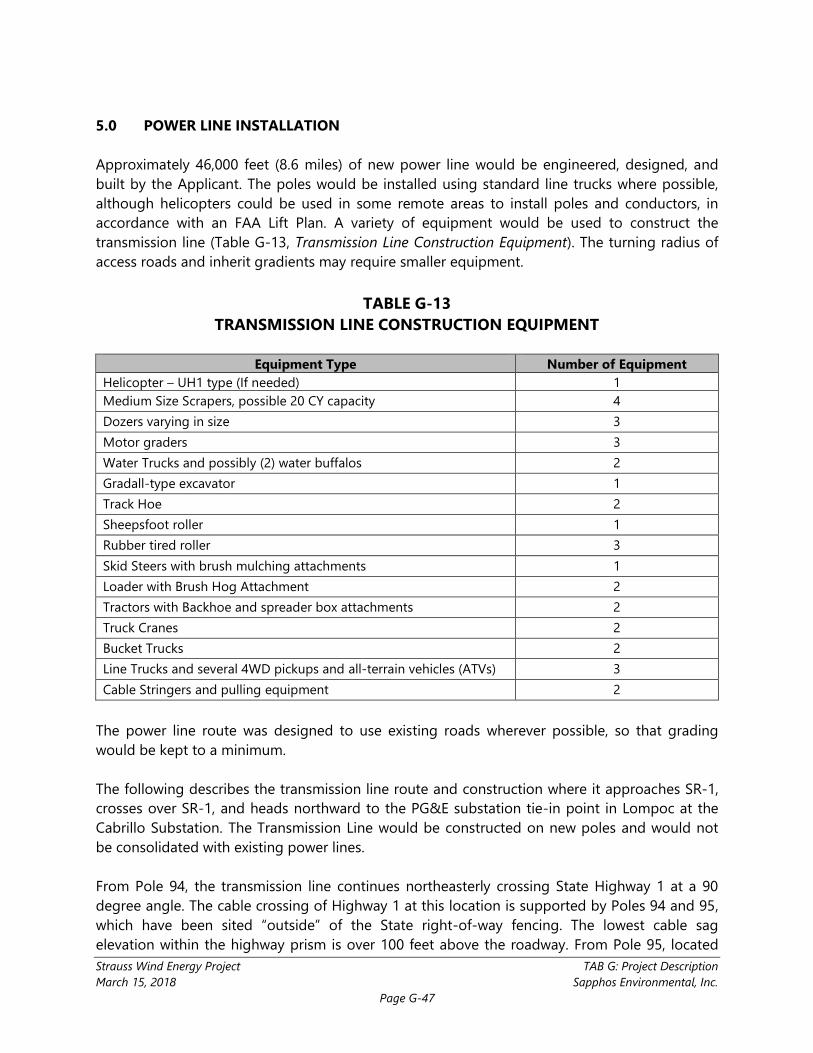
Strauss Wind Energy Project TAB G: Project Description
March 15, 2018 Sapphos Environmental, Inc.
Page G-47
5.0 POWER LINE INSTALLATION
Approximately 46,000 feet (8.6 miles) of new power line would be engineered, designed, and
built by the Applicant. The poles would be installed using standard line trucks where possible,
although helicopters could be used in some remote areas to install poles and conductors, in
accordance with an FAA Lift Plan. A variety of equipment would be used to construct the
transmission line (Table G-13, Transmission Line Construction Equipment). The turning radius of
access roads and inherit gradients may require smaller equipment.
TABLE G-13
TRANSMISSION LINE CONSTRUCTION EQUIPMENT
Equipment Type Number of Equipment
Helicopter – UH1 type (If needed) 1
Medium Size Scrapers, possible 20 CY capacity 4
Dozers varying in size 3
Motor graders 3
Water Trucks and possibly (2) water buffalos 2
Gradall-type excavator 1
Track Hoe 2
Sheepsfoot roller 1
Rubber tired roller 3
Skid Steers with brush mulching attachments 1
Loader with Brush Hog Attachment 2
Tractors with Backhoe and spreader box attachments 2
Truck Cranes 2
Bucket Trucks 2
Line Trucks and several 4WD pickups and all-terrain vehicles (ATVs) 3
Cable Stringers and pulling equipment 2
The power line route was designed to use existing roads wherever possible, so that grading
would be kept to a minimum.
The following describes the transmission line route and construction where it approaches SR-1,
crosses over SR-1, and heads northward to the PG&E substation tie-in point in Lompoc at the
Cabrillo Substation. The Transmission Line would be constructed on new poles and would not
be consolidated with existing power lines.
From Pole 94, the transmission line continues northeasterly crossing State Highway 1 at a 90
degree angle. The cable crossing of Highway 1 at this location is supported by Poles 94 and 95,
which have been sited “outside” of the State right-of-way fencing. The lowest cable sag
elevation within the highway prism is over 100 feet above the roadway. From Pole 95, located

Strauss Wind Energy Project TAB G: Project Description
March 15, 2018 Sapphos Environmental, Inc.
Page G-48
just east of the east right-of-way line of State Highway 1, the transmission line departs
northward running parallel, but “outside” of the east right-of-way fence of Highway 1, for
roughly 1,200 feet to the south right of way of State Highway 246. At this location, the line
crosses State Highway 246 roughly 125 feet east of the centerline intersection with State
Highway 1. This crossing location is a 260 foot span between Poles 103 and 104, and is
sufficiently east of the intersection to avoid conflict with the existing traffic signal. At this point,
two alternatives are proposed for the transmission line.
Alternative A continues to Pole 104, on the north side of State Highway 246, and then departs
westerly to cross over to the west side of North 12th Street to Pole 105. Crossing to the west
side of 12th Street is necessary to avoid conflicts with existing overhead utility lines running
along the east side. From Pole 105, the transmission line departs northerly within the right-of-
way of 12th Street, but “behind” the sidewalk, running roughly 490 feet and crossing to the
north side of Industrial Way. At this location, the transmission line departs northwesterly and
runs 100 feet into the PG&E Lompoc Substation.
Alternative B continues easterly from Pole 104 for approximately 760 feet to a pole location,
then departs north for approximately 400 feet to another pole location. From here, the
Alternative B turns westerly for approximately 960 feet north of East Laurel Avenue to a
switchyard. Construction of Alternative B could be accomplished using existing dirt access roads.
Additionally, all watercourse crossings could be avoided. Construction of both of these
alternatives will require new transmission poles. These poles will not exceed the height of
existing power poles that connect to the Cabrillo Substation (Transmission Line Route, in the
Maps Tab).
It is estimated that to construct the transmission line, approximately 4.4 miles of new access
roads will need to be graded. Approximately 13.5 miles of existing roads will require widening or
other improvements that will include grading. Earthwork amounts for these road improvements
are provided in Table G-12. It is anticipated that the excess fill associated with the transmission
line road improvements will be used in the same general vicinity as the cut locations. For
example, much of the excess cut would be used for fill needed for the roads in the same area. In
addition, many of road improvements for the transmission line will occur within the footprint of
the project site allowing for the convenient use of excess cut associated with these roads to be
used as fill for the project O&M facility or in others local areas on the project site. With
anticipated shrinkage and subsidence the total Project cut and fill is anticipated to “balance.”
Ground disturbance and tree removal will occur during construction of the transmission line.
Existing dirt roads will be used to access pole locations. Vegetation clearing would be kept to a
minimum because the power line route could be shifted within the study corridor to avoid
impacts to sensitive plant communities where feasible. The transmission line route, proposed
new and existing roads needed to access the alignment for construction, and the extent of
vegetation and tree removal are shown on Transmission Line Route (in the Maps tab).
Strauss Wind Energy Project TAB G: Project Description
March 15, 2018 Sapphos Environmental, Inc.
Page G-49
5.1 Step 1 – Installing the Supporting Structure Foundations
To install steel poles, a foundation hole would be excavated; forms, rebar, and anchor bolts
would be installed; concrete poured; forms removed; soil or gravel replaced around the base;
and a pole installed at each of the new pole sites. Installation of wood poles would involve
excavating, installing the pole, and backfilling the excavation; no foundation would be required
for poles placed in straight spans. Wooden poles may be embedded to a depth of
approximately 7 to 12 feet below grade. Material removed during the process would be placed
in a location specified by the landowner and/or disposed of according to applicable laws.
Temporary disturbance around each structure site would typically be limited to approximately a
50-foot radius (100-foot diameter) centered on the pole. Areas of temporary disturbance from
power line construction are listed in Table G-11. Temporary disturbance would consist of soil
compaction from placement of crane outrigger pads and from vehicle tracks, as well as
movement of workers and equipment.
Placement of the pole structures would require the use of a large auger to dig the foundation
hole. The foundation hole would be approximately 5 feet in diameter and from 10 to 20 feet
deep. In some cases, a cage of reinforced steel and with anchor bolts would be installed and
concrete would be placed in the hole. After the concrete curing period of one month, workers
would remove the concrete forms and restore the ground around the foundations. Each pole
would have approximately a 5-foot-diameter foundation (approximately 20 square feet of new
foundation per structure); areas of temporary and permanent disturbance are shown in Table G-
11.
5.2 Step 2 – Erecting the Supporting Structures
The poles would be installed by conventional methods or by helicopter, as needed. The steel
pole shafts may be delivered to the pole site in two or more sections depending on pole design.
For safety and ease of construction, the steel poles would be assembled on the ground in the
pole laydown area. The sections would be pulled together with a winch and the cross arms
bolted to the pole. Insulators would be attached to the cross arms and secured. A crane may be
used to erect the poles and set them in the excavation, or on the anchor bolts embedded in the
concrete foundation for certain steel poles. Finally, the securing nuts on the foundation would
be tightened.
Strauss Wind Energy Project TAB G: Project Description
March 15, 2018 Sapphos Environmental, Inc.
Page G-50
5.3 Step 3 – Stringing the Conductors
Before beginning conductor installation, temporary clearance structures would be installed at
road crossings and other locations where the new conductors could accidentally come into
contact with electrical or communication facilities and or vehicular traffic during installation. The
construction contractor would use a set of temporary clearance structures at all roads, railroad
crossings, and other power line crossings. These temporary clearance structures would be of
wood pole construction that resembles an “H” or “Y,” depending on the design, and placed on
each side of the roadway. These structures would be placed at the edge of the roadway and
would not require grading; they would not interfere with traffic. These structures would prevent
the conductor from being lowered or falling onto the traffic below before tensioning.
The conductor stringing operation would begin with the installation of insulators and sheaves or
stringing blocks. The sheaves are rollers attached to the lower end of the insulators that are, in
turn, attached to the ends of each supporting structure cross arm. The sheaves would allow the
individual conductors to be pulled through each structure until the conductors are ready to be
pulled up to the final tension position.
When the pull and tension equipment are set in place, a sock line (a small cable used to pull the
conductor) would be pulled from pole to pole, either using a helicopter to place the sock line
into the sheaves or using a guide to shoot the sock line from one pole to another. After the sock
line is installed, the conductors would be attached to the sock line and pulled in, or strung using
the tension stringing method. This method would involve pulling the conductor through each
pole under controlled tension to keep the conductors elevated above crossing guard structures,
roads, and other facilities.
After the conductors are pulled into place, wire or conductor sags would be adjusted to a pre-
calculated level. The conductors would then be clamped to the end of each insulator as the
sheaves are removed. The final step of conductor installation would be to install vibration
dampers and other accessories. The temporary crossing guard structures would be removed
after the final step.
Packing crates, spare bolts, and construction debris would be picked up and hauled away for
recycling or disposal during construction. The construction contractor would conduct a final
survey to ensure that cleanup activities have been completed as required.
Strauss Wind Energy Project TAB G: Project Description
March 15, 2018 Sapphos Environmental, Inc.
Page G-51
6.0 OPERATION
During the operational phase of the Project, approximately five to seven staff would be
employed onsite in the O&M facility. Monitoring of WTGs and system operation would occur in
the O&M facility. Staff on-site would perform routine maintenance throughout the site,
troubleshoot malfunctions, and shut down and restart WTGs when necessary. Operations would
be continuously monitored through the SCADA system.
Larger equipment, supplies, and spare parts would be stored in a secured on-site yard, while
normal-sized equipment, supplies, and spare parts would be stored inside the O&M facility’s
shop area. The secured yard would be located adjacent to the O&M facility that would only be
accessible to authorized personnel. Spare parts might include large components, such as a spare
blade set or gearbox. Specialized equipment not needed routinely would be brought onsite as
needed. Maintenance of some components of onsite infrastructure (for example, roads and
electrical lines) may be subcontracted to qualified local firms.
6.1 Wind Turbine Generator Maintenance
After the initial startup period, the WTGs would be serviced at regular intervals, taking them
offline for one or two days, typically one or two WTGs at a time, depending on the maintenance
strategy. Annual overhaul maintenance service would also be performed. The service program is
expected to maintain the WTGs at operational availability 98 percent of the time. Most servicing
would be performed onsite without using a crane. Service access would be from inside the
tower, via a door in the base. The regular routine would consist of inspecting and testing all
safety systems; inspecting wear-and-tear on components, such as seals, bearings, and bushings;
lubricating the mechanical systems; performing electronic diagnostics on the control systems;
pre-tension verification of mechanical fasteners; and inspecting the overall structural
components of the WTGs. Electrical equipment, such as breakers, relays, and transformers, are
frequently visually inspected, which would not affect overall availability, and testing or
calibrations every 1 to 3 years, which might force outages. Blade cleaning can be considered
when the accumulation of debris on the lead edge reduces aerodynamic performance. WTG
tower and blade cleaning is a reactive maintenance activity, not preventative, so there is not a
defined periodicity for this work. In the event excessive dirt, grease, or oil is found on the
external surfaces of the WTG (hub, blades, nacelle, tower) an evaluation would be performed to
determine a safe (personnel, environment or equipment) method of cleaning. In the majority of
the cleaning cases, a lift basket is used to hoist a wind turbine technician who then use a
biodegradable cleaner and cloths to perform the cleaning. Cleaning cloth disposal would be
contracted through a licensed and approved waste management company in the area. In the
event additional cleaning such as pressure washing is required, a third party would be
contracted. The standard for pressure washing is that the vendor would truck water to the site
and use an environmentally friendly biodegradable cleaner. Cranes and other large equipment
would not be used for routine operation and maintenance activities.
Strauss Wind Energy Project TAB G: Project Description
March 15, 2018 Sapphos Environmental, Inc.
Page G-52
If a crane is needed for an unanticipated maintenance or blade replacement in the case of a
blade failure (blade failure is an extremely rare occurrence and is not expected throughout the
life of the project), it would be brought to the site unassembled so that roads would not have to
be re-widened for maintenance, repair activities or blade delivery.
6.2 Road Maintenance
Project access roads would be periodically graded and compacted to maintain the design,
safety, and environmental requirements during the life of the Project. Maintenance of cut-and-
fill slopes, culverts, grade separations, and drainage areas would be performed as necessary to
minimize erosion problems and maintain functional drainage structures. The Applicant would be
responsible for cleaning up all construction debris and maintaining the appearance of all Project
roads and rights-of-way in cooperation with the Project landowners.
6.3 Emergency Situations
In the event that severe storms result in a downed overhead line, procedures outlined in the
emergency response plan would be applied. Tensioning sites would be located within the
overhead distribution line rights-of-way to facilitate line replacements. In the event of a high-
voltage grid outage, the WTGs would have internal protective control mechanisms to safely shut
them down. The WTGs would require the grid to be energized to generate power when the wind
is blowing. A separate low-voltage distribution service feed may be connected to the low-
voltage side of the Project Substation as a backup system to provide auxiliary power to Project
facilities in case of outages. If low voltage service is not available, a back-up generator powered
by Liquid Petroleum Gas will be used to provide back-up power in case of an unscheduled
outage.
The power from the turbines would be transmitted to a pad mount step-up transformer
adjacent to the tower that would step-up the voltage from 690 kV to 34.5 kV. From there, the
power would be transmitted via the collection system. The collection systems would all
terminate at the Project substation. All underground collection circuits would be buried in
trenches 3 to 4 feet deep. The size of the buried cable would vary depending on the type of
cable used and how many turbines are interconnected on the specific circuit. The cables are
shipped on cable reels. Each circuit is to consist of three 34.5-kV, single-conductor cables with
tree retardant polyethylene insulation. The cables would be direct buried in a trefoil
configuration together with the communication fiber cable and the ground wire. Sectionalizing
connections would be made in above-ground, locked junction boxes.
Strauss Wind Energy Project TAB G: Project Description
March 15, 2018 Sapphos Environmental, Inc.
Page G-53
Underground marker balls would be installed at multiple locations to support identification of
the collector system underground path. Overhead markers/stakes would also be installed at
multiple locations. After the collection system is installed, the disturbed area would be reclaimed
using a pre-approved seed mix. Typical installation of the collection system generally involves
the following:
The exact location of the collection system trench is surveyed and staked using a
registered surveyor.
A grader is deployed to make two passes along the trench running line to move
the topsoil away to the side, if topsoil is to be preserved.
Trenching is typically performed using a mechanized trencher or excavator.
The trenching spoil is typically deposited adjacent to the open trench.
The conductor cables, neutral cable and fiber optic cable get installed. Usually a
truck pulls the cable reels adjacent to the trench to lay the cables simultaneously.
In some cases, the cable reels are pulled by the trencher itself and immediately
installed in the trench behind the trencher.
A paddling machine usually follows the trencher to screen the spoil and deposit
clean spoil on the collection system cables.
This screened spoil that was deposited in the trench on top of the cables is then
compacted, usually using a small compactor.
The remaining spoil is then deposited into the trench, and compaction is usually
specified as 95 percent of natural compaction.
The topsoil is then bladed back over the trench using a grader.
During the operation term, the collection system would be energized at all times unless the
facility is taken offline or certain segments are isolated for repair or maintenance. Power
generated by the wind turbines would be transmitted via this collection system. When the
turbines are not producing power (e.g. low winds, curtailment, maintenance, etc.), the collection
system would remain energized under a parasitic load to power the turbines and their control
systems.
Strauss Wind Energy Project TAB G: Project Description
March 15, 2018 Sapphos Environmental, Inc.
Page G-54
Public access to public areas would not be impeded by the Project because the proposed
facilities are located on private property (except the section of the power line that follows San
Miguelito Road). For safety, the Project Substation would be fenced, locked, and properly signed
to prevent access to high-voltage equipment. Safety signage would be posted around WTGs,
transformers, other high-voltage facilities, and along roads, as required. The Project site is within
the County’s High Fire Hazard Area. Vegetation would be cleared and clearance maintained
around the Project Substation, transformers, and riser poles.
6.4 Public Access
During the construction, and possibly during the operational phase of the Project, the Project
operator and landowners using San Miguelito Road and Sudden Road beyond their intersection
may request the County to close these roads to public travel. Only the landowners involved in
the Project and VAFB would use these roads. A turnaround area would be provided at the end of
the public road near the entrance of the Project. This Project component would benefit Project
safety and security.
During construction, access to adjacent properties would be maintained. However, some
interruptions are anticipated. Local roadways have constraints that limit their potential to be
used by large trucks. In particular, San Miguelito Road has overhanging trees that may be lower
than the vertical clearances of the trucks, and its horizontal curves south of Miguelito County
Park have relatively small radii that will require improvement. In order to make these
improvements, traffic may need to be temporarily stopped using flaggers or traffic control
devices.
Informational signs would be used to inform public of temporary traffic hazards. Flaggers and
traffic cones would be utilized where any temporary changes to lane configuration are made
while making the necessary improvements. Deliveries of the turbine equipment would comply
with all permit requirements. Any routing plans, road restriction information, pilot vehicle
requirements, and other permit conditions required by the permits will be observed. If during
construction road widths are insufficient to accommodate traffic flow in both directions
simultaneously, then traffic may need to be temporarily stopped using flaggers or traffic control
devices.
6.5 Hazardous Materials Handling
Hazardous and potentially hazardous chemicals (for example, oil, grease, ethylene glycol) would
be used to lubricate and cool the WTGs and ancillary facilities; a radiator would dissipate heat
and would contain a water and ethylene mixture that would be tested annually. The gearbox
would contain approximately 70 gallons of oil that would not be routinely renewed. The WTGs
would be equipped with leak-proof gaskets. Possible leakage or spillage during WTG operation
and maintenance would be confined within the towers. A supply of chemicals would be stored
at a facility in close proximity to the site to allow and facilitate maintenance and repair.
Chemicals would be stored in tanks or drums located within secondary containment areas at the

Strauss Wind Energy Project TAB G: Project Description
March 15, 2018 Sapphos Environmental, Inc.
Page G-55
designated storage facility. Use of extremely hazardous materials is not anticipated. Storage and
use of hazardous materials would be subject to a Hazardous Materials Management Plan
approved by the SBCFD, which would include safe handling practices from the Material Safety
Data Sheets (MSDS).
6.6 Safety Procedures
Standard operating procedures and employee training relating to safety, potential emergency
situations, and potential malfunctions would address emergency evacuation, emergency
response, safety, electrical equipment failures, fire prevention and control, mechanical
malfunctions, notification procedures, maintenance activities, and schedules.
Standard operating procedures dictate that WTGs would not be operated at high wind speeds
because of the high loads exerted on the equipment. The maximum operating wind speed
would be in the range 25 meters per second or 60 miles per hour, depending on the specific
model chosen. In higher wind speeds, for equipment protection, the blades would feather and
the rotor would free-spin with very low rotational speed.
Physical security of the Project site is provided by the installation of locked gates at the entrance
to all access roads. In addition, all turbines would be locked as well, as would be the Project
substation and control house, which would be fenced by an 8-foot high barbed wire reinforced
fence. Additionally, remote, around the clock monitoring and surveillance cameras would
provide eyes on the wind facilities at all times and report any and all suspected intrusions. If an
intrusion is suspected, security personnel would be deployed to the site.
Strauss Wind Energy Project TAB G: Project Description
March 15, 2018 Sapphos Environmental, Inc.
Page G-56
7.0 DECOMMISSIONING
The anticipated life of the Project is 30 years. At the end of its useful life, the Project could be
“repowered,” renovated or upgraded, or decommissioned. The decision to decommission or
repower would depend on energy economics at the time, technological options, and other
considerations.
If the Project were repowered, full or partial decommissioning would likely be required before
repowering. Depending on the new WTG model selected, some of the Project components
could be reused. At this time, projections of what technology would be used to repower the
facility cannot be determined. As a result, there is no estimate of what components would be
reused or what types of road improvements or modifications would be needed to facilitate
decommissioning.
If or when the Project is decommissioned, all structures and equipment at the site would be
dismantled and removed, and the land surface would be restored to as close to the original
condition as possible. Reclamation would be conducted on all disturbed areas to comply with
County reclamation policy. The short-term goal would be to stabilize disturbed areas as rapidly
as possible, thereby protecting sites and adjacent undisturbed areas from degradation.
The leases with local landowners require the Applicant to prepare a reclamation plan for the
Project. The County would also require a discretionary permit and a decommissioning and
reclamation plan to be developed and implemented. The Applicant proposes that the
decommissioning plan would, at a minimum, (1) identify and discuss the proposed
decommissioning activities and how they would comply with the applicable regulatory
requirements, and (2) describe alternative decommissioning activities.
Decommissioned underground buried cables would remain. The following components
proposed would be removed:
WTGs, including foundations, to a level 4 feet below the existing grade
Overhead poles and electric lines within the Project area
Project Substation
Project roads, unless the Project landowners wish to retain the improved roads
for access throughout their property.
If towers are sold for reuse, they would be dismantled at their bolted joints, removed by crane,
and trucked off the site in the same way they were delivered. This might require the roads to be
widened to the original construction width for crane access. Units sold as scrap would most
likely not require widening of the roads for removal.
Strauss Wind Energy Project TAB G: Project Description
March 15, 2018 Sapphos Environmental, Inc.
Page G-57
8.0 PROTECTION MEASURES
Several types of protection measures would be implemented during Project construction and
operation. These measures include the following:
A Quality Assurance/Quality Control (QA/QC) Program would ensure that
engineering, procurement, construction, and startup are completed.
A mitigation monitoring and reporting plan (MMRP) would be required by the
County as part of the CEQA process and would ensure compliance with County
permit conditions and applicable environmental regulations.
A safety plan would ensure compliance with health and safety regulations.
An Applicant-committed mitigation program discussed in Section 8.4 below, would
implement measures to minimize potential Project impacts to acceptable levels.
8.1 Quality Assurance and Quality Control (QA/QC), Environmental, and Health and
Safety Compliance
8.1.1 QA/QC
A QA/QC Program would be implemented during the construction and operational phase of the
Project to ensure that the engineering, procurement, construction, and startup of the facility are
completed as specified. A Project construction procedures manual will be prepared and
approved prior to any site construction. The manual would describe how the contractors would
implement and maintain QA/QC, environmental compliance programs, and health and safety
compliance programs, and integrate their activities with the other contractors during all phases
of the work. The Engingeering, Procurement, and Construction contractor(s) (EPC) and WTG
supplier would be responsible for enforcing compliance with the construction procedures
program of all of its subcontractors. In the QA/QC Program, the contractor would describe the
activities and responsibilities within its organization and the measures to be taken to ensure
quality work on the Project. Some topics that would be covered are design control,
configuration management, and drawing control. Independent QA/QC personnel would review
all documentation (for example, design, engineering, and procurement) and witness field
activities as a parallel organization to that of the construction contractors to ensure compliance
with the specifications. Field inspectors’ acceptance would be required for installation, alignment
and commissioning of all major equipment.
Strauss Wind Energy Project TAB G: Project Description
March 15, 2018 Sapphos Environmental, Inc.
Page G-58
8.1.2 Environmental Compliance
An MMRP would ensure that construction activities meet the conditions, limits, and
specifications set in environmental standards established in the Project’s CUP and other
applicable environmental regulations. Copies of all applicable construction permits would be
kept onsite. The lead Project construction personnel and construction Project managers would
be required to read, follow, and be responsible for required compliance activities. The
environmental compliance program would cover avoidance of sensitive areas during
construction, waste handling and storage, stormwater management, spill prevention and
control, and other components required by State and County regulations. Upon identification of
an environmental non-compliance issue, the EPC work with the responsible subcontractor to
correct the violation.
To avoid potential damage to underground utilities, such as water lines and facilities (for
example, in the City of Lompoc near the Frick Springs facilities), an Underground Service Alert
survey would be completed before construction activities begin.
8.1.3 Safety Compliance
Each EPC contractor would be responsible for construction-period health and safety issues. Each
EPC contractor would provide a Health and Safety Coordinator, who would ensure that all laws,
ordinances, regulations, and standards concerning health and safety are followed and that any
identified deficiencies are corrected as quickly as possible. The EPC Health and Safety
Coordinator would conduct onsite orientation and safety training for all contract and
subcontract employees and would report back to EPC corporate management. The EPC Health
and Safety Coordinator would have the authority to stop work when health and safety
regulations, including EPC subcontractor safety regulations, are violated and the health or safety
of construction personnel are in danger. For health and safety stop work orders, the action
might affect only the portion of the work that endangers a limited portion of the Project site or
activities. The Project construction procedures would clearly define the stop work procedures,
which would require a written action request with justification on the part of the EPC Health and
Safety Coordinator. Upon identification of a health and safety issue, the EPC Health and Safety
Coordinator would work with the responsible subcontractor or direct hire workers to correct the
violation; if not corrected in a reasonable period of time, a stop work order could be issued. The
stop work authority would also be given to the Project Construction Manager for commercial
actions and health and safety issues.
8.2 Recommended Mitigation Measures
A number of recommended mitigation measures for the Project are included in the individual
technical reports included in the appendices.
Strauss Wind Energy Project TAB G: Project Description
March 15, 2018 Sapphos Environmental, Inc.
Page G-59
9.0 PROJECT APPROVALS
A number of permits and approvals would be required for the Project, as described in this
section.
9.1 County of Santa Barbara
The County of Santa Barbara would need to authorize or approve the following items:
Conditional Use Permit (CUP), pursuant to Santa Barbara County LUDC Section
35.82.060.
Two variances, as specified in LUDC Section 35.57.050:
o Variance No. 1: To allow the base of the tower of the WTG to be setback 65
meters (213 feet) feet from the property line adjoining the VAFB.
o Variance No. 2: To allow the removal of all setback requirements from internal
property lines.
Coastal Development Permit (CDP) - (County & State Approval)
The Project would require a total of 12.1 acres of grading for road
improvements to access WTGs in the south eastern portion of the Project
site. Coastal Development Permit (CDP)
The County Planning Commission will consider each of these actions. Approval would not be
required by the Board of Supervisors unless the CUP or variances are appealed. After approval of
the CUP and variances, and after the necessary permit conditions are satisfied, the County would
issue zoning clearances.
Strauss Wind Energy Project TAB G: Project Description
March 15, 2018 Sapphos Environmental, Inc.
Page G-60
Other permits or approvals may that may be needed from individual County agencies are as
follows:
Planning and Development Department: Approval of all environmental
mitigation plans and future review and approval of the Decommissioning and
Site Restoration Plan
Public Works Department: Stormwater Quality Management Plan incorporating
Best Management Practices (BMPs)
Flood Control District: Plan approval for any road or bridge crossings at creeks
or grading for structures within 50 feet from the top of creek banks.
Environmental Health Services: Water system/Supply permits for the O&M
Building
Air Pollution Control District. None required. The Project would use electric
pumps and would be conditioned to require that all construction equipment use
ultra-low-sulfur diesel fuel. No permanent stationary sources would occur.
However, portable or temporary equipment present onsite for more than 12
months, including concrete batch plants, associated engines, and gasoline
storage tanks of 250 gallons or more, would require permits.
Public Works Department / Roads Division
o Encroachment permits
o Detailed traffic control plan
o Fees for increases in peak hour trips, if required
o Haul permits
o Bonds
o Photo documentation of pre- and post-construction road condition of San
Miguelito Road beyond the Celite mine and payment for resulting road
damage
Santa Barbara County Fire Department (SBCFD)
o Annual permits for the use and storage of hazardous and flammable
materials/wastes
o Hazardous Materials Business Plan
o Fire Protection Plan
Building and Safety Division
o Grading and drainage plan and permit
o Erosion control plan and permit
o Building and electrical permits
Strauss Wind Energy Project TAB G: Project Description
March 15, 2018 Sapphos Environmental, Inc.
Page G-61
9.2 Other Permits and Approvals
Additional permits, approvals, and consultations may be needed from the following entities:
City of Lompoc: Encroachment permits for work within the City’s right-of-way
and approval of the Traffic Control Plan
Coastal Development Permit (CDP) - (County & State Approval)
o The Project would require a total of 12.1 acres of grading for road
improvements to access WTGs in the south eastern portion of the Project site.
Central Coast Regional Water Quality Control Board. Regional Water Quality
Certification (401 permit) , Industrial National Pollutant Discharge Elimination
System (NPDES) permit, and General Construction Stormwater permit
(requirements include preparation of a SWPPP)
California Department of Fish and Wildlife (CDFW)
o Possible Streambed Alteration Agreement (pursuant to Section 1601 of the
California Fish and Game Code)
o Possible Section 2081 permit (for impacts to state-listed endangered species)
California Department of Transportation (Caltrans)
o Encroachment permit (for any portions of the power line that extend into or
across the SR-1 right-of-way)
o Hauling truck and overload permits
o Approve road closures
United States Army Corps of Engineers (USACE): Possible Nationwide Permit or
Section 404 permit
United States Fish and Wildlife Service (USFWS): Consultation for impacts to
federally listed species
Federal Aviation Administration (FAA)
o Review Notice of Proposed Construction or Alteration and make
determination regarding the Project’s impact to air navigation
o Review and approve Lift Plan and WTG Lighting Plan
Strauss Wind Energy Project TAB G: Project Description
March 15, 2018 Sapphos Environmental, Inc.
Page G-62
10. REFERENCES
APLIC. 2006. Suggested Practices for Avian Protection on Power Lines: The State of the Art in 2006.
Available at: http://www.aplic.org/suggested practices2006(LR).pdf
ATS Projects Wind Energy Services. February 24, 2017. Strauss Wind Project Review.
CPUC. 2006. EMF Design Guidelines for Electrical Facilities. Available at:
http://www.cpuc.ca.gov/WorkArea/DownloadAsset.aspx?id=4884
J.C. Brennan and Associates. April 19, 2017. Environmental Noise Analysis – Strauss Wind Energy
Facility. See Appendix H.
Ninyo & Moore. (2011) April 27, 2017. Geotechnical Evaluation, Strauss Wind Energy Project,
Santa Barbara County, CA. See Appendix E.
U.S. Energy Information Administration. 2015. Average monthly residential electricity
consumption, prices, and bills by state. Available at:
https://www.eia.gov/tools/faqs/faq.php?id=97&t=3

Strauss Wind Energy Project TAB G: Project Description
March 15, 2018 Sapphos Environmental, Inc.
Page G-63
11. FIGURES