Embed Size (px)
Citation preview
www.knick.deLatest Product Information:
Stratos®Pro A4... OXYUser Manual
2
Warranty. Disposal. About This Manual.WarrantyDefects occurring within 3 years from delivery date shall be remedied free of charge at our plant (carriage and insurance paid by sender).Sensors, fittings and accessories: 1 year.Subject to change without notice.
Return of products under warrantyPlease contact our Service Team before returning a defective device. Ship the cleaned device to the address you have been given. If the device has been in contact with process fluids, it must be de-contaminated/disinfected before shipment. In that case, please attach a corresponding certificate, for the health and safety of our service personnel.
DisposalPlease observe the applicable local or national regulations concerning the disposal of “waste electrical and electronic equipment”.
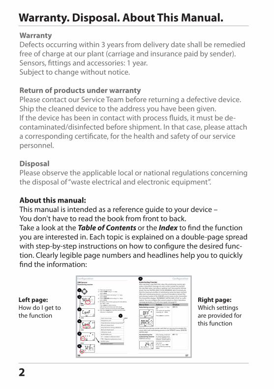
About this manual:This manual is intended as a reference guide to your device – You don't have to read the book from front to back.Take a look at the Table of Contents or the Index to find the function you are interested in. Each topic is explained on a double-page spread with step-by-step instructions on how to configure the desired func-tion. Clearly legible page numbers and headlines help you to quickly find the information:
56 57
ConfigurationISM SensorAutoclaving counter
Select sensor type
Temperature unit
Temp detection during measurement
(Manual temperature)
Temp detection during calibration
(Manual temperature)
Calibration mode
(AuTo: Buffer set)
ACT - Adaptive calibration timer
TTM - Adaptive maintenance timer
CIP/SIP cycles
Autoclaving counter
ConfigurationAutoclaving CounterAfter reaching a specified limit value the autoclaving counter gen-erates a Sensoface message. As soon as the counter has reached the specified value, Sensoface is getting “sad”. Pressing the info key shows the text “AuToCLAVE CYCLES oVERRuN” which reminds you that the maximum number of autoclaving cycles has been reached. After each autoclaving process, you must manually increment the autoclaving counter in the SENSoR service menu on the transmitter. The transmitter displays “INCREMENT AuToCLAVE CYCLE” as confir-mation. You can configure the current outputs so that a Sensoface message generates a 22-mA error signal, see page 63.
Menu item Action ChoicesAutoclaving counter Select using keys:
oN:The cycles are specified manually (0 ... 9999)
Press enter to confirm.
With the autoclaving counter switched on, you must increment the count after each autoclaving process in the SERVICE menu SENSoR/AuToCLAVE : Incrementing the autoclaving counter(SERVICE menu)
After having completed an autoclaving process, open the SERVICE menu SENSoR / AuToCLAVE to increment the autoclav-ing count. To do so, select “YES” and confirm by pressing enter.
1) Press any arrow key.2) Select CONF using keys,
press enter.3) Select parameter set using keys,
press enter.4) Select SENSOR menu using keys,
press enter. 5) All items of this menu group are indicated by
the “SNS:” code. Press enter to select menu, edit using arrow keys (see next page). Confirm (and proceed) by pressing enter.
6) Exit: Press meas key until the [meas] mode indicator is displayed.
Left page:How do I get to the function
Right page:Which settings are provided for this function
3
Documents Supplied
CD-ROMComplete documentation:• User manuals• Safety instructions • Certificates• Short instructions
Safety InformationIn official EU languages and others.• EC Declarations of Conformity
Short InstructionsFirst steps after installation:• Operation• Menu structure• Calibration• Error messages and recommended actionsIn German, English, French, Russian, Spanish, Portuguese, Italian, Swedish and Dutch. More languages on CD-ROM and on our website: www.knick.de
Specific Test Report
Certificates• IECEx• ATEX• FM• CSA• NEPSI• GOST
4
ContentsDocuments Supplied .............................................................................. 3
Introduction ............................................................................................. 7Intended Use ....................................................................................................7
Safety Information ................................................................................ 12Safety Precautions for Installation .........................................................13
Overview of Stratos Pro A4... OXY ...................................................... 14
Assembly ................................................................................................. 15Package Contents .........................................................................................15Mounting Plan, Dimensions .....................................................................16Pipe Mounting, Protective Hood ............................................................17Panel Mounting .............................................................................................18
Installation .............................................................................................. 19Installation Instructions .............................................................................19Rating Plates / Terminal Assignments...................................................20Power Supply, Signal Lines .......................................................................21Sensor Connection ......................................................................................22Wiring Examples ...........................................................................................23Protective Wiring of Relay Contacts ......................................................26
User Interface, Keypad ......................................................................... 28
Display ..................................................................................................... 29Signal colors (display backlighting) .......................................................29
Measuring Mode.................................................................................... 30Selecting the Mode / Entering Values ..................................................31Display in Measuring Mode ......................................................................32
Color-Coded User Interface ................................................................. 33
Operating Modes ................................................................................... 34Menu Structure of Modes and Functions ............................................35HOLD Mode ....................................................................................................37Alarm .................................................................................................................38Alarm and HOLD Messages ......................................................................39
5
ContentsConfiguration ......................................................................................... 40
Parameter Set A/B ........................................................................................42Parameter Sets (Original for Copy) ........................................................50Sensor ...............................................................................................................54Current Output 1 ..........................................................................................66Current Output 2 ..........................................................................................74Correction .......................................................................................................76Parameter set selection via external signal ........................................78Flow measurement ......................................................................................80Alarm Settings ...............................................................................................82Limit Function ................................................................................................86Pulse Length / Pulse Frequency Controller.........................................95Controller .......................................................................................................96WASH Contact ............................................................................................100Time and Date ............................................................................................102Tag Number ................................................................................................102
Digital Sensors .....................................................................................104Memosens Sensors: Calibration and Maintenance in the Lab ..........................................104Memosens Sensors: Configuring the Device .................................105Replacing a Sensor....................................................................................106
Calibration ............................................................................................108Selecting a Calibration Mode ...............................................................109Zero Calibration .........................................................................................110Product Calibration ...................................................................................112Slope Calibration (Medium: Water) .....................................................114Slope Calibration (Medium: Air) ...........................................................115Temp Probe Adjustment .........................................................................116
Measurement .......................................................................................117
Diagnostics ...........................................................................................119
Service ...................................................................................................124
Operating States ..................................................................................129
6
ContentsProduct Line and Accessories ...........................................................131
Specifications .......................................................................................132
Error Handling ......................................................................................141
Error Messages .....................................................................................142
Sensoface ..............................................................................................145
FDA 21 CFR Part 11 .............................................................................148Electronic Signature – Passcodes ........................................................148Audit Trail .....................................................................................................148
Index ......................................................................................................149Trademarks ..................................................................................................163
Passcodes ..............................................................................................164
7
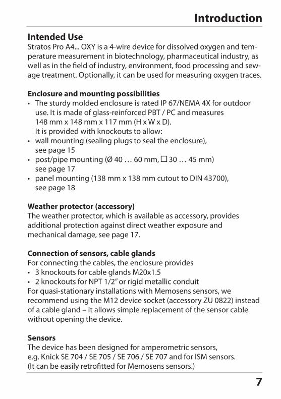
IntroductionIntended UseStratos Pro A4... OXY is a 4-wire device for dissolved oxygen and tem-perature measurement in biotechnology, pharmaceutical industry, as well as in the field of industry, environment, food processing and sew-age treatment. Optionally, it can be used for measuring oxygen traces.
Enclosure and mounting possibilities• The sturdy molded enclosure is rated IP 67/NEMA 4X for outdoor
use. It is made of glass-reinforced PBT / PC and measures 148 mm x 148 mm x 117 mm (H x W x D). It is provided with knockouts to allow:
• wall mounting (sealing plugs to seal the enclosure), see page 15
• post/pipe mounting (Ø 40 … 60 mm, 30 … 45 mm)see page 17
• panel mounting (138 mm x 138 mm cutout to DIN 43700), see page 18
Weather protector (accessory)The weather protector, which is available as accessory, provides additional protection against direct weather exposure and mechanical damage, see page 17.
Connection of sensors, cable glandsFor connecting the cables, the enclosure provides• 3 knockouts for cable glands M20x1.5• 2 knockouts for NPT 1/2” or rigid metallic conduitFor quasi-stationary installations with Memosens sensors, we recommend using the M12 device socket (accessory ZU 0822) instead of a cable gland – it allows simple replacement of the sensor cable without opening the device.
SensorsThe device has been designed for amperometric sensors, e.g. Knick SE 704 / SE 705 / SE 706 / SE 707 and for ISM sensors.(It can be easily retrofitted for Memosens sensors.)
8
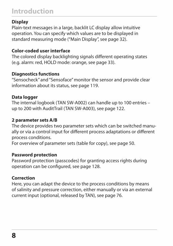
DisplayPlain-text messages in a large, backlit LC display allow intuitive operation. You can specify which values are to be displayed in standard measuring mode (“Main Display”, see page 32).
Color-coded user interfaceThe colored display backlighting signals different operating states (e.g. alarm: red, HOLD mode: orange, see page 33).
Diagnostics functions“Sensocheck” and “Sensoface” monitor the sensor and provide clear information about its status, see page 119.
Data loggerThe internal logbook (TAN SW-A002) can handle up to 100 entries – up to 200 with AuditTrail (TAN SW-A003), see page 122.
2 parameter sets A/BThe device provides two parameter sets which can be switched manu-ally or via a control input for different process adaptations or different process conditions.For overview of parameter sets (table for copy), see page 50.
Password protectionPassword protection (passcodes) for granting access rights during operation can be configured, see page 128.
CorrectionHere, you can adapt the device to the process conditions by means of salinity and pressure correction, either manually or via an external current input (optional, released by TAN), see page 76.
Introduction
9
5
6
13
11
12
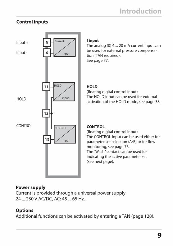
I inputThe analog (0) 4 ... 20 mA current input can be used for external pressure compensa-tion (TAN required).See page 77.
Control inputs
HOLD (floating digital control input)The HOLD input can be used for external activation of the HOLD mode, see page 38.
CONTROL (floating digital control input)The CONTROL input can be used either for parameter set selection (A/B) or for flow monitoring, see page 78. The “Wash” contact can be used for indicating the active parameter set (see next page).
Power supplyCurrent is provided through a universal power supply 24 ... 230 V AC/DC, AC: 45 ... 65 Hz.
OptionsAdditional functions can be activated by entering a TAN (page 128).
Current input
HOLD input
CONTROL input
Introduction
10
Introduction
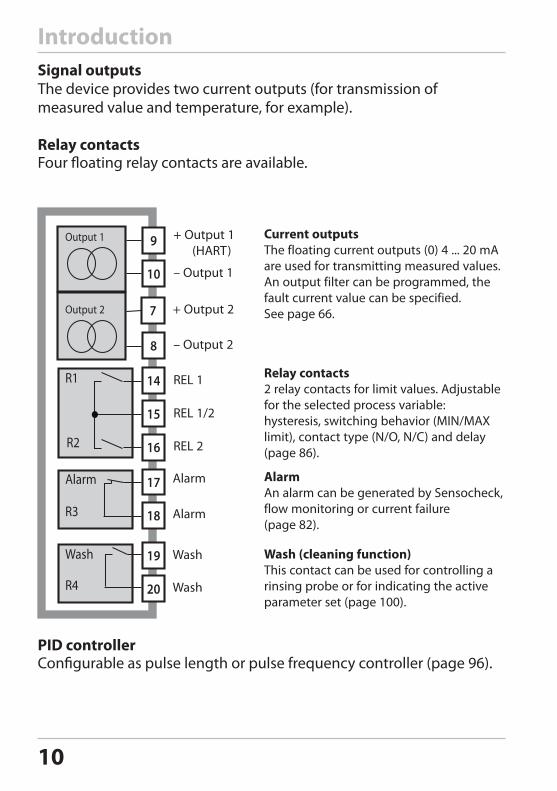
Current outputsThe floating current outputs (0) 4 ... 20 mA are used for transmitting measured values. An output filter can be programmed, the fault current value can be specified. See page 66.
Relay contacts 2 relay contacts for limit values. Adjustable for the selected process variable: hysteresis, switching behavior (MIN/MAX limit), contact type (N/O, N/C) and delay (page 86).
Wash (cleaning function) This contact can be used for controlling a rinsing probe or for indicating the active parameter set (page 100).
Signal outputsThe device provides two current outputs (for transmission of measured value and temperature, for example).
Relay contactsFour floating relay contacts are available.
8
10
9Output 1
Output 2 7
14
15
16
17
18
19
20
R1
R2
Alarm
R3
R4
Wash
Alarm An alarm can be generated by Sensocheck, flow monitoring or current failure (page 82).
PID controllerConfigurable as pulse length or pulse frequency controller (page 96).
11
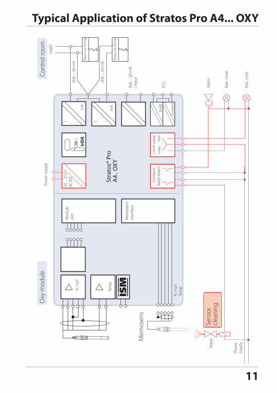
Typical Application of Stratos Pro A4... OXY
Stra
tos®
Pro
A4.
. OXY
12
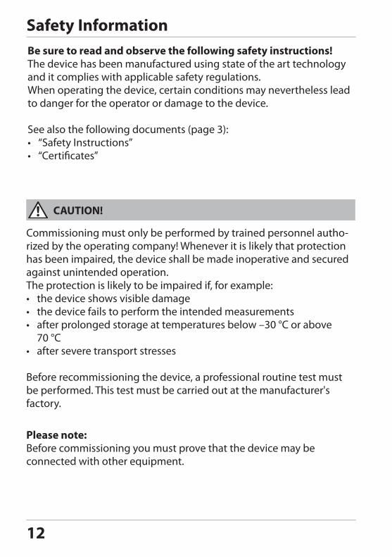
Safety InformationBe sure to read and observe the following safety instructions!The device has been manufactured using state of the art technology and it complies with applicable safety regulations.When operating the device, certain conditions may nevertheless lead to danger for the operator or damage to the device.
See also the following documents (page 3):• “Safety Instructions”• “Certificates”
CAUTION!
Please note:Before commissioning you must prove that the device may be connected with other equipment.
Commissioning must only be performed by trained personnel autho-rized by the operating company! Whenever it is likely that protection has been impaired, the device shall be made inoperative and secured against unintended operation. The protection is likely to be impaired if, for example:• the device shows visible damage• the device fails to perform the intended measurements• after prolonged storage at temperatures below –30 °C or above
70 °C• after severe transport stresses
Before recommissioning the device, a professional routine test must be performed. This test must be carried out at the manufacturer's factory.
13
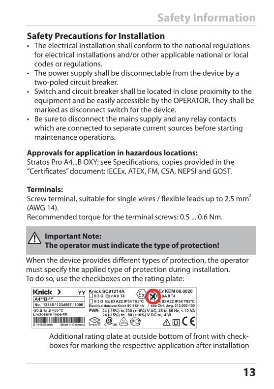
Safety InformationSafety Precautions for Installation• The electrical installation shall conform to the national regulations
for electrical installations and/or other applicable national or local codes or regulations.
• The power supply shall be disconnectable from the device by a two-poled circuit breaker.
• Switch and circuit breaker shall be located in close proximity to the equipment and be easily accessible by the OPERATOR. They shall be marked as disconnect switch for the device.
• Be sure to disconnect the mains supply and any relay contacts which are connected to separate current sources before starting maintenance operations.
Approvals for application in hazardous locations:Stratos Pro A4...B OXY: see Specifications, copies provided in the “Certificates” document: IECEx, ATEX, FM, CSA, NEPSI and GOST.
Terminals:Screw terminal, suitable for single wires / flexible leads up to 2.5 mm2 (AWG 14).Recommended torque for the terminal screws: 0.5 ... 0.6 Nm.
When the device provides different types of protection, the operator must specify the applied type of protection during installation. To do so, use the checkboxes on the rating plate:
Additional rating plate at outside bottom of front with check-boxes for marking the respective application after installation
Important Note: The operator must indicate the type of protection!
14
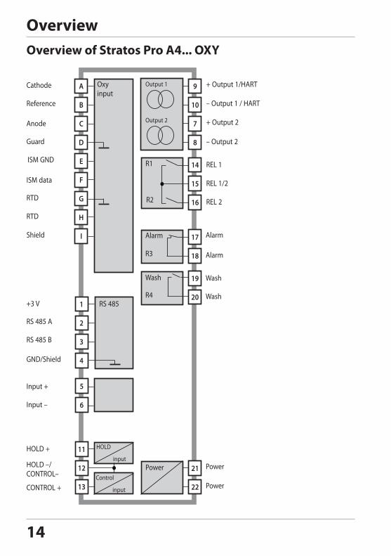
OverviewOverview of Stratos Pro A4... OXY
7
8
14
15
16
1
2
3
4
17
18
19
20
21
22
10
9
C
D
E
F
G
H
I
5
6
11
12
13
B
A Output 1Oxy input
HOLD input
Output 2
R1
R2
Alarm
R3
R4
Wash
Power
RS 485
Control input
15
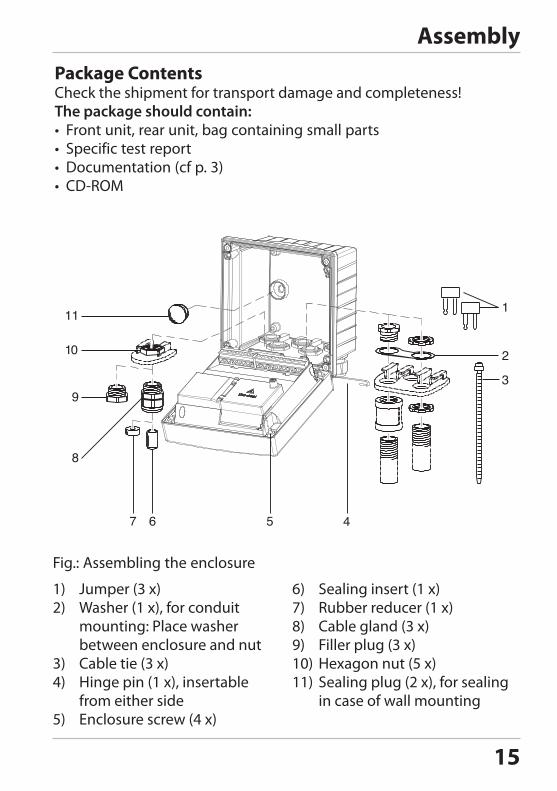
AssemblyPackage ContentsCheck the shipment for transport damage and completeness!The package should contain:• Front unit, rear unit, bag containing small parts• Specific test report• Documentation (cf p. 3)• CD-ROM
11
10
9
8
7 6 5 4
1
2
3
Fig.: Assembling the enclosure
1) Jumper (3 x)2) Washer (1 x), for conduit
mounting: Place washer between enclosure and nut
3) Cable tie (3 x)4) Hinge pin (1 x), insertable
from either side5) Enclosure screw (4 x)
6) Sealing insert (1 x)7) Rubber reducer (1 x)8) Cable gland (3 x)9) Filler plug (3 x)10) Hexagon nut (5 x)11) Sealing plug (2 x), for sealing
in case of wall mounting
16
AssemblyMounting Plan, Dimensions
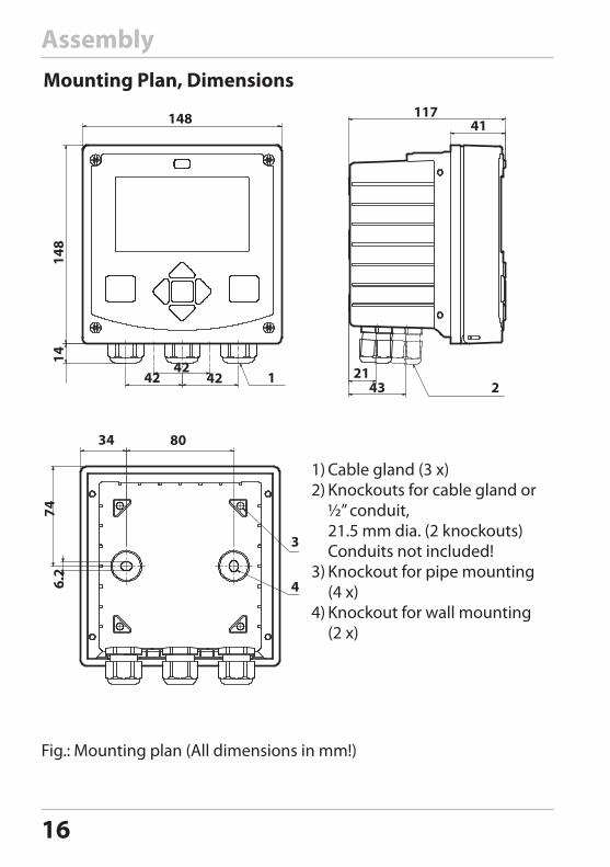
Fig.: Mounting plan (All dimensions in mm!)
1) Cable gland (3 x)2) Knockouts for cable gland or
½” conduit, 21.5 mm dia. (2 knockouts) Conduits not included!
3) Knockout for pipe mounting (4 x)
4) Knockout for wall mounting (2 x)
148
148
42 4242
14
11741
2143
12
34 80
746.
2
4
3
17
AssemblyPipe Mounting, Protective Hood
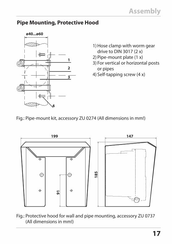
Fig.: Protective hood for wall and pipe mounting, accessory ZU 0737(All dimensions in mm!)
Fig.: Pipe-mount kit, accessory ZU 0274 (All dimensions in mm!)
147199
91
185
1
2
3
4
1) Hose clamp with worm gear drive to DIN 3017 (2 x)
2) Pipe-mount plate (1 x)3) For vertical or horizontal posts
or pipes4) Self-tapping screw (4 x)
ø40...ø60
18
AssemblyPanel Mounting
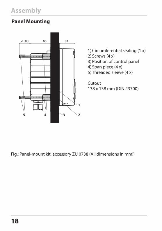
Fig.: Panel-mount kit, accessory ZU 0738 (All dimensions in mm!)
1) Circumferential sealing (1 x)2) Screws (4 x)3) Position of control panel4) Span piece (4 x)5) Threaded sleeve (4 x)
Cutout 138 x 138 mm (DIN 43700)
< 30 76 31
1...221
2345
19
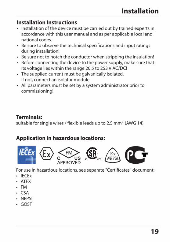
InstallationInstallation Instructions• Installation of the device must be carried out by trained experts in
accordance with this user manual and as per applicable local and national codes.
• Be sure to observe the technical specifications and input ratings during installation!
• Be sure not to notch the conductor when stripping the insulation!• Before connecting the device to the power supply, make sure that
its voltage lies within the range 20.5 to 253 V AC/DC!• The supplied current must be galvanically isolated.
If not, connect an isolator module.• All parameters must be set by a system administrator prior to
commissioning!
Terminals: suitable for single wires / flexible leads up to 2.5 mm2 (AWG 14)
For use in hazardous locations, see separate "Certificates" document:• IECEx• ATEX• FM• CSA• NEPSI• GOST
Application in hazardous locations:
20
InstallationRating Plates / Terminal Assignments
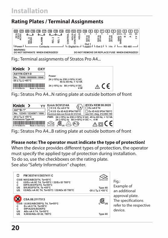
Fig.: Terminal assignments of Stratos Pro A4...
Fig.: Stratos Pro A4...N rating plate at outside bottom of front
Fig.: Stratos Pro A4...B rating plate at outside bottom of front
Please note: The operator must indicate the type of protection!When the device provides different types of protection, the operator must specify the applied type of protection during installation. To do so, use the checkboxes on the rating plate.See also “Safety Information“ chapter.
Fig.: Example of an additional approval plate.The specifications refer to the respective device.
21
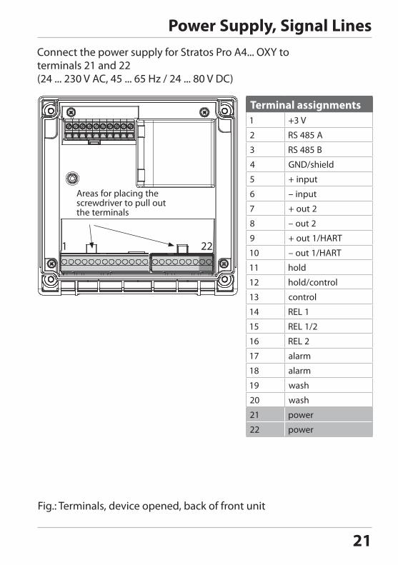
Power Supply, Signal LinesConnect the power supply for Stratos Pro A4... OXY to terminals 21 and 22(24 ... 230 V AC, 45 ... 65 Hz / 24 ... 80 V DC)
Terminal assignments
1 22
Fig.: Terminals, device opened, back of front unit
Areas for placing the screwdriver to pull out the terminals
22
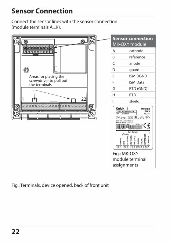
Connect the sensor lines with the sensor connection (module terminals A...K).
Sensor Connection
Areas for placing the screwdriver to pull out the terminals
1 22
Fig.: Terminals, device opened, back of front unit
Sensor connectionMK-OXY module
Fig.: MK-OXY module terminal assignments
23
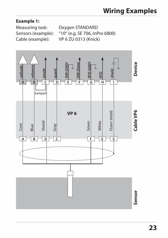
Wiring ExamplesExample 1:Measuring task: Oxygen STANDARDSensors (example): “10“ (e.g. SE 706, InPro 6800)Cable (example):
B C D E F G HA I
cath
ode
refe
ence
anod
e
guar
d
ISM
(GN
D)
ISM
(Dat
a)
RTD
(GN
D)
shie
ld
RTD
B D CA F E S
VP 6
Core
Blue
Shie
ld
Gra
y
Sens
orCa
ble
VP6
Dev
ice
Jumper!G
reen
Whi
te
Out
er s
hiel
d
24
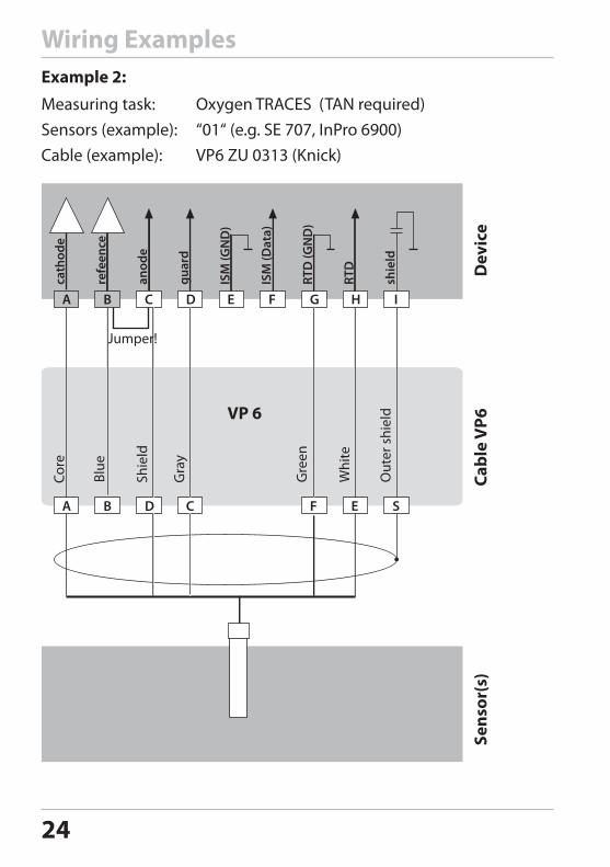
Wiring ExamplesExample 2:
Measuring task: Oxygen TRACES (TAN required)Sensors (example): “01“ (e.g. SE 707, InPro 6900)Cable (example):
B C D E F G HA I
cath
ode
refe
ence
anod
e
guar
d
ISM
(GN
D)
ISM
(Dat
a)
RTD
(GN
D)
shie
ld
RTD
B D CA F E S
VP 6
Gre
en
Whi
teJumper!
Core
Blue
Out
er s
hiel
d
Shie
ld
Gra
y
Sens
or(s
)Ca
ble
VP6
Dev
ice
25
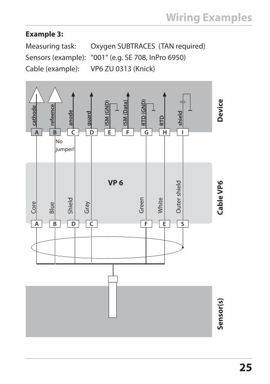
Wiring ExamplesExample 3:
Measuring task: Oxygen SUBTRACES (TAN required)Sensors (example): “001“ (e.g. SE 708, InPro 6950)Cable (example):
B C D E F G HA I
cath
ode
refe
ence
anod
e
guar
d
ISM
(GN
D)
ISM
(Dat
a)
RTD
(GN
D)
shie
ld
RTD
B D CA F E S
VP 6
Gre
en
Whi
te
No jumper!
Core
Blue
Out
er s
hiel
d
Shie
ld
Gra
y
Sens
or(s
)Ca
ble
VP6
Dev
ice
26
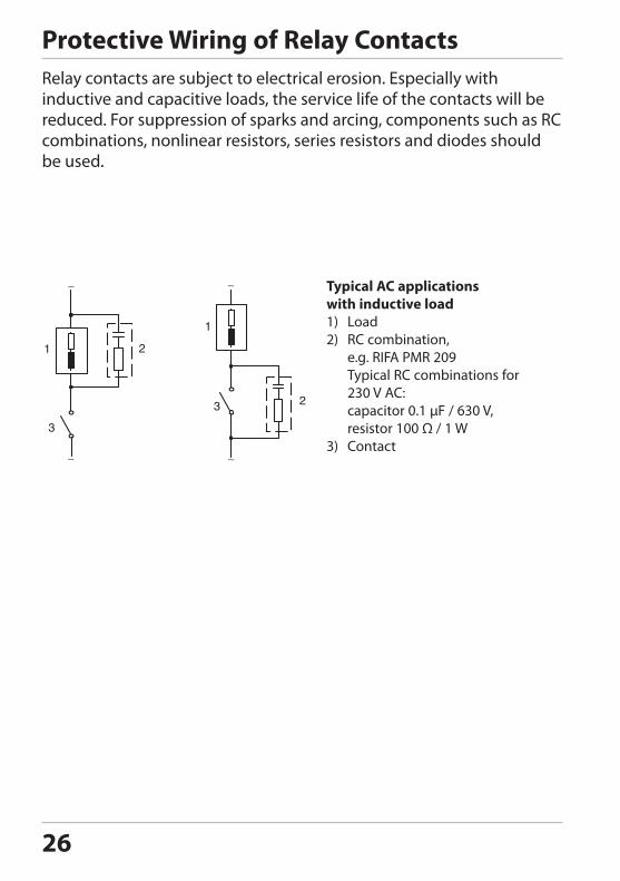
Protective Wiring of Relay ContactsRelay contacts are subject to electrical erosion. Especially with inductive and capacitive loads, the service life of the contacts will be reduced. For suppression of sparks and arcing, components such as RC combinations, nonlinear resistors, series resistors and diodes should be used.
Typical AC applicationswith inductive load1) Load2) RC combination,
e.g. RIFA PMR 209 Typical RC combinations for 230 V AC: capacitor 0.1 µF / 630 V, resistor 100 Ω / 1 W
3) Contact
1
23
1 2
3
27
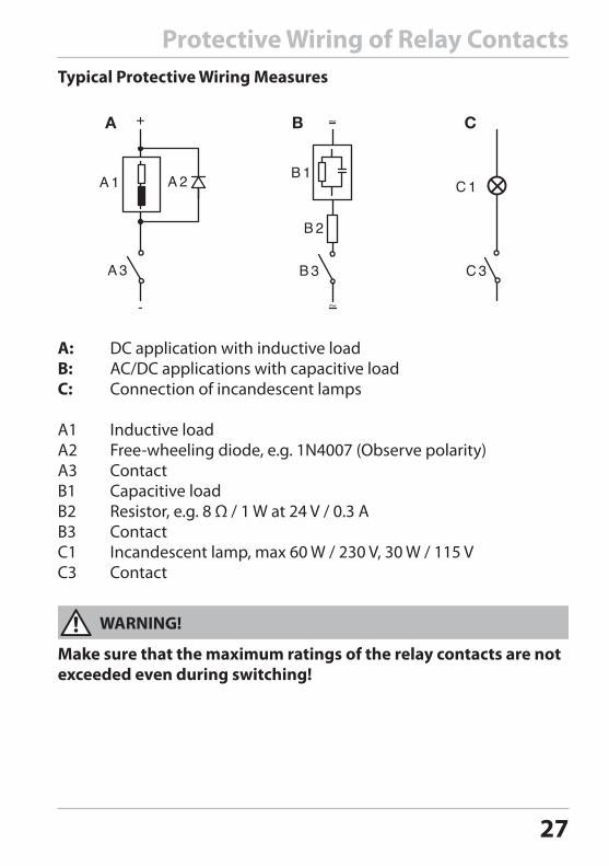
Protective Wiring of Relay Contacts
A: DC application with inductive loadB: AC/DC applications with capacitive loadC: Connection of incandescent lamps
A1 Inductive loadA2 Free-wheeling diode, e.g. 1N4007 (Observe polarity)A3 ContactB1 Capacitive loadB2 Resistor, e.g. 8 Ω / 1 W at 24 V / 0.3 AB3 ContactC1 Incandescent lamp, max 60 W / 230 V, 30 W / 115 VC3 Contact
Make sure that the maximum ratings of the relay contacts are not exceeded even during switching!
Typical Protective Wiring Measures
WARNING!
28
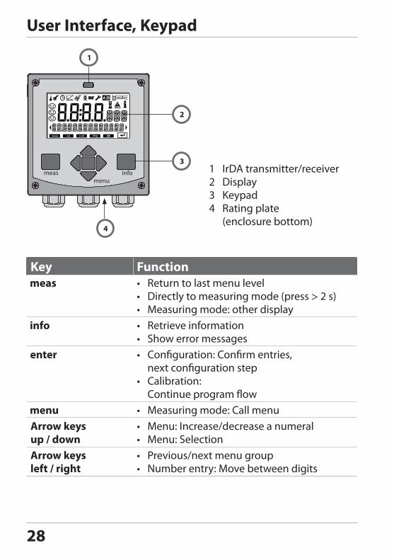
User Interface, Keypad
1 IrDA transmitter/receiver2 Display3 Keypad4 Rating plate (enclosure bottom)
1
3
4
2
MEMO SENS
Key Function• Return to last menu level• Directly to measuring mode (press > 2 s)• Measuring mode: other display• Retrieve information• Show error messages• Configuration: Confirm entries,
next configuration step• Calibration:
Continue program flow• Measuring mode: Call menu
Arrow keysup / down
• Menu: Increase/decrease a numeral• Menu: Selection
Arrow keysleft / right
• Previous/next menu group• Number entry: Move between digits
29
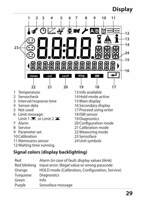
Display
MEMO SENS
1 Temperature2 Sensocheck3 Interval/response time4 Sensor data5 Not used6 Limit message: Limit 1 or Limit 2 7 Alarm8 Service9 Parameter set10 Calibration11 Memosens sensor12 Waiting time running
13 Info available14 Hold mode active15 Main display16 Secondary display17 Proceed using enter18 ISM sensor19 Diagnostics20 Configuration mode21 Calibration mode22 Measuring mode23 Sensoface24 Unit symbols
1 2 3 4 5 6 7 8 9 10 11
171819202122
121314
15
16
2324
Signal colors (display backlighting)
RedRed blinking
Alarm (in case of fault: display values blink)Input error: illegal value or wrong passcode
Orange HOLD mode (Calibration, Configuration, Service)Turquoise DiagnosticsGreen InfoPurple Sensoface message
30
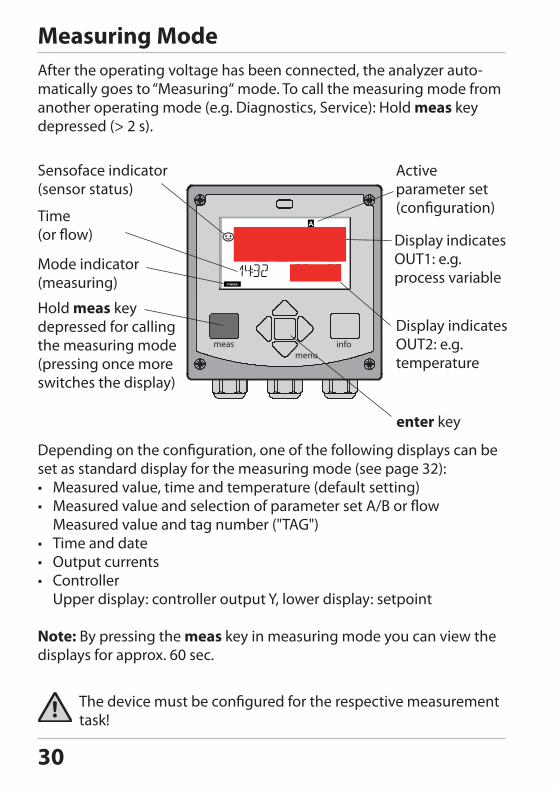
Measuring ModeAfter the operating voltage has been connected, the analyzer auto-matically goes to “Measuring“ mode. To call the measuring mode from another operating mode (e.g. Diagnostics, Service): Hold meas key depressed (> 2 s).
Depending on the configuration, one of the following displays can be set as standard display for the measuring mode (see page 32):• Measured value, time and temperature (default setting)• Measured value and selection of parameter set A/B or flow
Measured value and tag number ("TAG")• Time and date• Output currents• Controller
Upper display: controller output Y, lower display: setpoint
Note: By pressing the meas key in measuring mode you can view the displays for approx. 60 sec.
The device must be configured for the respective measurement task!
Sensoface indicator(sensor status)
Time(or flow)
Mode indicator (measuring)
Hold meas key depressed for calling the measuring mode(pressing once more switches the display)
Active parameter set (configuration)
Display indicates OUT1: e.g. process variable
Display indicates OUT2: e.g. temperature
enter key
31
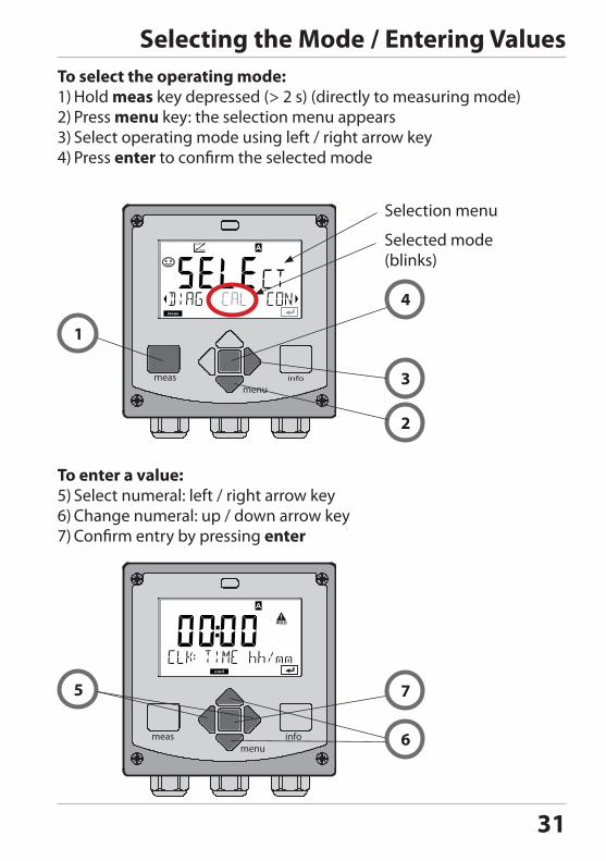
Selecting the Mode / Entering Values
To enter a value:5) Select numeral: left / right arrow key6) Change numeral: up / down arrow key7) Confirm entry by pressing enter
To select the operating mode:1) Hold meas key depressed (> 2 s) (directly to measuring mode)2) Press menu key: the selection menu appears3) Select operating mode using left / right arrow key4) Press enter to confirm the selected mode
Selection menu
Selected mode (blinks)
1
4
3
2
5 7
6
32
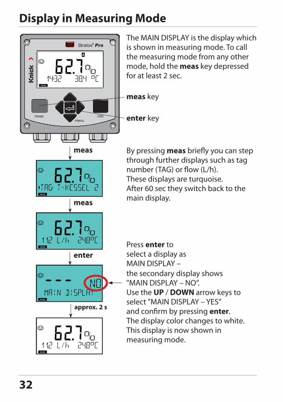
Display in Measuring Mode
enter key
meas key
By pressing meas briefly you can step through further displays such as tag number (TAG) or flow (L/h).These displays are turquoise. After 60 sec they switch back to the main display.
The MAIN DISPLAY is the display which is shown in measuring mode. To call the measuring mode from any other mode, hold the meas key depressed for at least 2 sec.
approx. 2 s
Press enter to select a display as MAIN DISPLAY –the secondary display shows "MAIN DISPLAY – NO“. Use the UP / DOWN arrow keys to select "MAIN DISPLAY – YES“ and confirm by pressing enter.The display color changes to white.This display is now shown in measuring mode.
33
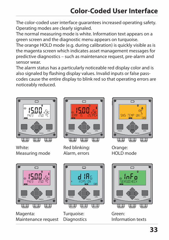
Color-Coded User InterfaceThe color-coded user interface guarantees increased operating safety. Operating modes are clearly signaled.The normal measuring mode is white. Information text appears on a green screen and the diagnostic menu appears on turquoise. The orange HOLD mode (e.g. during calibration) is quickly visible as is the magenta screen which indicates asset management messages for predictive diagnostics – such as maintenance request, pre-alarm and sensor wear.The alarm status has a particularly noticeable red display color and is also signaled by flashing display values. Invalid inputs or false pass-codes cause the entire display to blink red so that operating errors are noticeably reduced.
White:Measuring mode
Orange:HOLD mode
Red blinking:Alarm, errors
Magenta:Maintenance request
Green:Information texts
Turquoise:Diagnostics
34
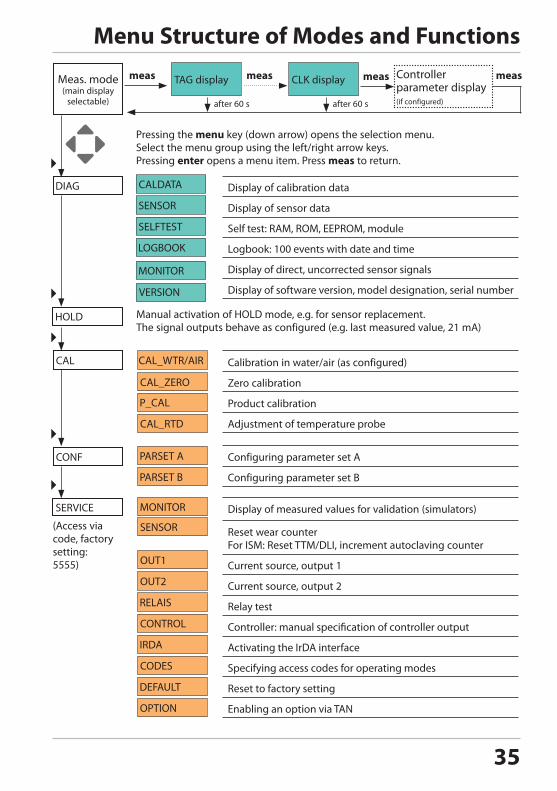
DiagnosticsDisplay of calibration data, display of sensor data, performing a device self-test, viewing the logbook entries, display of hardware/software ver-sions of the individual components. The logbook can store 100 events (00...99). They can be displayed directly on the device. The logbook can be extended to 200 entries using a TAN (Option).
HOLDManual activation of HOLD mode, e.g. for replacing a digital sensor. The signal outputs adopt a defined state.
CalibrationEvery sensor has typical characteristic values, which change in the course of the operating time. Calibration is required to supply a cor-rect measured value. The device checks which value the sensor delivers when measuring in a known solution. When there is a deviation, the device can be “adjusted“. In that case, the device displays the “actual“ value and internally corrects the measurement error of the sensor. Calibration must be repeated at regular intervals. The time between the calibration cycles depends on the load on the sensor. During calibration the device is in HOLD mode. During calibration the device remains in the HOLD mode until it is stopped by the operator.
ConfigurationThe analyzer must be configured for the respective measurement task. In the “Configuration“ mode you select the connected sensor, the measuring range to be transmitted, and the conditions for warning and alarm messages. During configuration the device is in HOLD mode. Configuration mode is automatically exited 20 minutes after the last keystroke. The device returns to measuring mode.
ServiceMaintenance functions (current source, relay test, controller test), IrDA operation, passcode assignment, reset to factory settings, enabling of options (TAN).
Operating Modes
35
Menu Structure of Modes and Functions
Display of calibration data
Display of sensor data
Self test: RAM, ROM, EEPROM, module
Logbook: 100 events with date and time
Display of direct, uncorrected sensor signals
Display of software version, model designation, serial number
Manual activation of HOLD mode, e.g. for sensor replacement.The signal outputs behave as configured (e.g. last measured value, 21 mA)
Calibration in water/air (as configured)
Zero calibration
Product calibration
Adjustment of temperature probe
Configuring parameter set A
Configuring parameter set B
Display of measured values for validation (simulators)
Reset wear counter For ISM: Reset TTM/DLI, increment autoclaving counter
Current source, output 1
Current source, output 2
Relay test
Controller: manual specification of controller output
Activating the IrDA interface
Specifying access codes for operating modes
Reset to factory setting
Enabling an option via TAN
(Access via code, factory setting:5555)
Pressing the menu key (down arrow) opens the selection menu. Select the menu group using the left/right arrow keys. Pressing enter opens a menu item. Press meas to return.
meas Controller parameter display(if configured)
meas meas
after 60 s after 60 s
measTAG display CLK displayMeas. mode(main display
selectable)

36
37
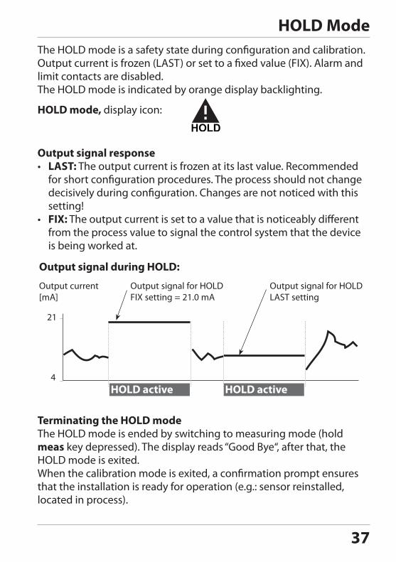
HOLD ModeThe HOLD mode is a safety state during configuration and calibration. Output current is frozen (LAST) or set to a fixed value (FIX). Alarm and limit contacts are disabled. The HOLD mode is indicated by orange display backlighting.
Terminating the HOLD mode The HOLD mode is ended by switching to measuring mode (hold meas key depressed). The display reads “Good Bye“, after that, the HOLD mode is exited. When the calibration mode is exited, a confirmation prompt ensures that the installation is ready for operation (e.g.: sensor reinstalled, located in process).
HOLD mode, display icon:
HOLD active
21
4HOLD active
Output current[mA]
Output signal for HOLDFIX setting = 21.0 mA
Output signal for HOLDLAST setting
Output signal during HOLD:
Output signal response• LAST: The output current is frozen at its last value. Recommended
for short configuration procedures. The process should not change decisively during configuration. Changes are not noticed with this setting!
• FIX: The output current is set to a value that is noticeably different from the process value to signal the control system that the device is being worked at.
38
Alarm
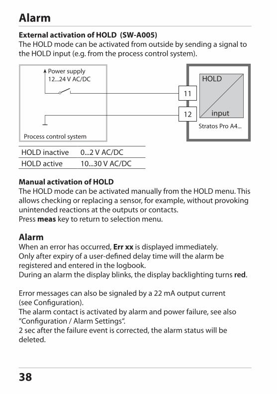
Manual activation of HOLDThe HOLD mode can be activated manually from the HOLD menu. This allows checking or replacing a sensor, for example, without provoking unintended reactions at the outputs or contacts.Press meas key to return to selection menu.
AlarmWhen an error has occurred, Err xx is displayed immediately.Only after expiry of a user-defined delay time will the alarm be registered and entered in the logbook.During an alarm the display blinks, the display backlighting turns red.
Error messages can also be signaled by a 22 mA output current (see Configuration).The alarm contact is activated by alarm and power failure, see also “Configuration / Alarm Settings“.2 sec after the failure event is corrected, the alarm status will be deleted.
External activation of HOLD (SW-A005)The HOLD mode can be activated from outside by sending a signal to the HOLD input (e.g. from the process control system).
HOLD inactive 0...2 V AC/DCHOLD active 10...30 V AC/DC
Process control system
Power supply12...24 V AC/DC
HOLD input
11
12
39
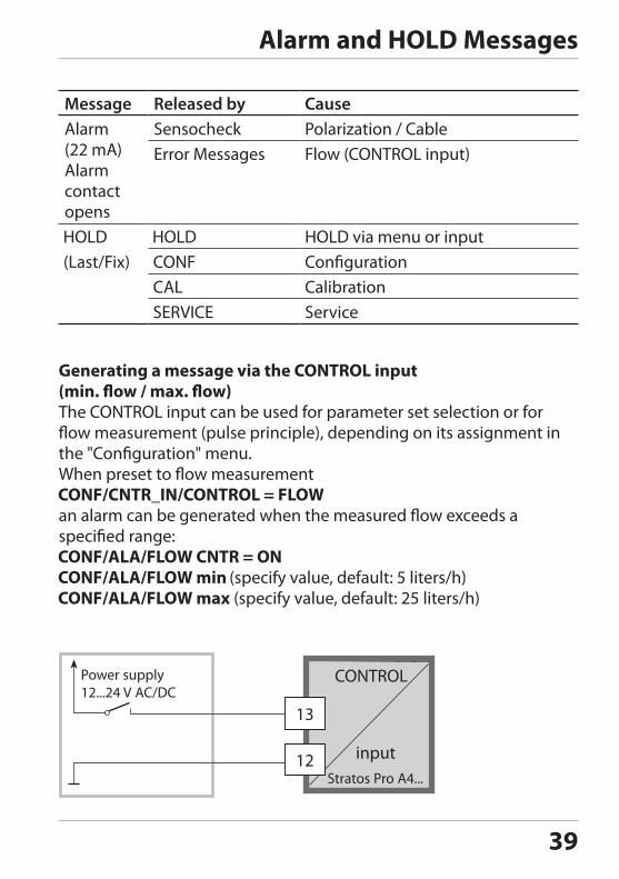
Message Released by CauseAlarm(22 mA)Alarm contact opens
Sensocheck Polarization / CableError Messages Flow (CONTROL input)
HOLD via menu or inputConfigurationCalibrationService
Alarm and HOLD Messages
Power supply12...24 V AC/DC
13
12
Generating a message via the CONTROL input(min. flow / max. flow)The CONTROL input can be used for parameter set selection or for flow measurement (pulse principle), depending on its assignment in the "Configuration" menu. When preset to flow measurement
an alarm can be generated when the measured flow exceeds a specified range:
(specify value, default: 5 liters/h) (specify value, default: 25 liters/h)
CONTROL input
40
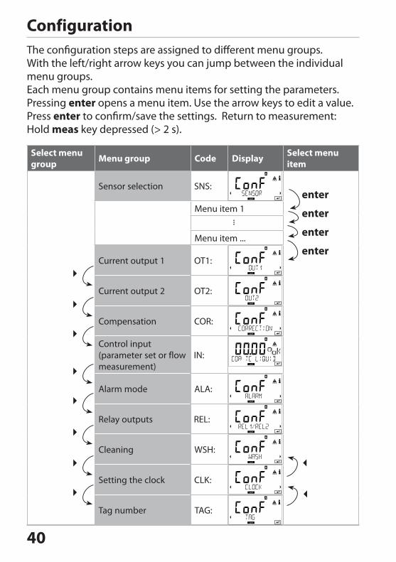
ConfigurationThe configuration steps are assigned to different menu groups.With the left/right arrow keys you can jump between the individual menu groups.Each menu group contains menu items for setting the parameters.Pressing enter opens a menu item. Use the arrow keys to edit a value. Press enter to confirm/save the settings. Return to measurement: Hold meas key depressed (> 2 s).
Select menu group Menu group Code Display Select menu
item
Sensor selection
Menu item 1
...
Menu item ...
Current output 1
Current output 2
Compensation
Control input(parameter set or flow measurement)
Alarm mode
Relay outputs
Cleaning
Setting the clock
Tag number
enter
enter
enter
enter
41
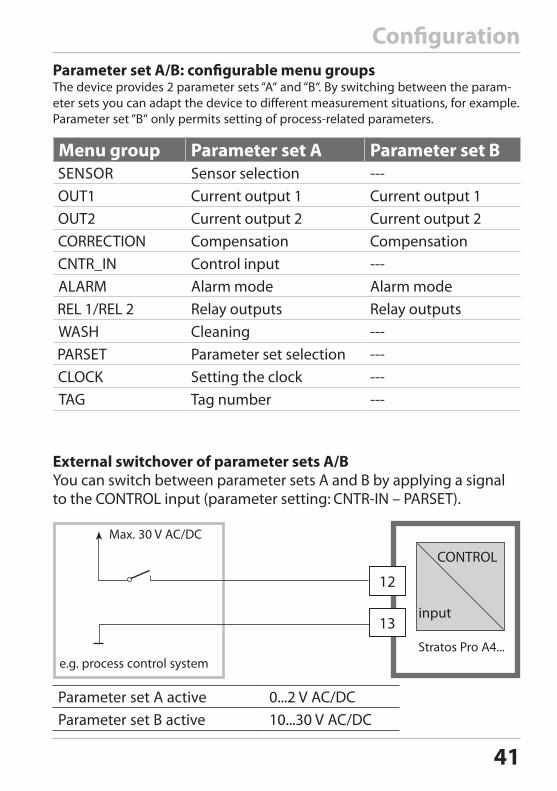
ConfigurationParameter set A/B: configurable menu groupsThe device provides 2 parameter sets “A“ and “B“. By switching between the param-eter sets you can adapt the device to different measurement situations, for example. Parameter set “B“ only permits setting of process-related parameters.
Menu group Parameter set A Parameter set B Sensor selection ---
Current output 1 Current output 1Current output 2 Current output 2Compensation CompensationControl input ---Alarm mode Alarm modeRelay outputs Relay outputsCleaning ---Parameter set selection ---Setting the clock ---Tag number ---
External switchover of parameter sets A/BYou can switch between parameter sets A and B by applying a signal to the CONTROL input (parameter setting: ).
12
13
Max. 30 V AC/DC
Parameter set A active 0...2 V AC/DCParameter set B active 10...30 V AC/DC
CONTROL input
e.g. process control system
42
19
20
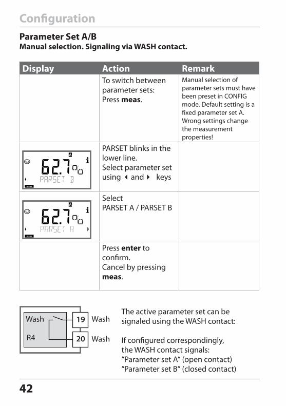
Parameter Set A/BManual selection. Signaling via WASH contact.
Display Action RemarkTo switch between parameter sets:Press meas.
Manual selection of parameter sets must have been preset in CONFIG mode. Default setting is a fixed parameter set A.Wrong settings change the measurement properties!
PARSET blinks in the lower line.Select parameter set using and keys
Select PARSET A / PARSET B
Press enter to confirm. Cancel by pressing meas.
The active parameter set can be signaled using the WASH contact: If configured correspondingly, the WASH contact signals:“Parameter set A“ (open contact)“Parameter set B“ (closed contact)
R4
Wash
Configuration
43
Configuration
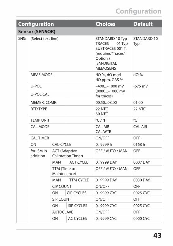
Configuration Choices DefaultSensor (SENSOR)SNS: (Select text line) STANDARD 10 Typ
TRACES 01 TypSUBTRACES 001 T.(requires “Traces“ Option )ISM-DIGITALMEMOSENS
STANDARD 10 Typ
MEAS MODE dO %, dO mg/ldO ppm, GAS %
dO %
U-POL –400...–1000 mV(0000...–1000 mVfor traces)
-675 mV
U-POL CAL
MEMBR. COMP. 00.50...03.00 01.00
RTD TYPE 22 NTC 30 NTC
22 NTC
TEMP UNIT °C / °F °C
CAL MODE CAL AIRCAL WTR
CAL AIR
CAL TIMER ON/OFF OFF
ON CAL-CYCLE 0...9999 h 0168 h
for ISM in addition
ACT (Adaptive Calibration Timer)
OFF / AUTO / MAN OFF
MAN ACT CYCLE 0...9999 DAY 0007 DAY
TTM (Time to Maintenance)
OFF / AUTO / MAN OFF
MAN TTM CYCLE 0...9999 DAY 0030 DAY
CIP COUNT ON/OFF OFF
ON CIP CYCLES 0...9999 CYC 0025 CYC
SIP COUNT ON/OFF OFF
ON SIP CYCLES 0...9999 CYC 0025 CYC
AUTOCLAVE ON/OFF OFF
ON AC CYCLES 0...9999 CYC 0000 CYC
44
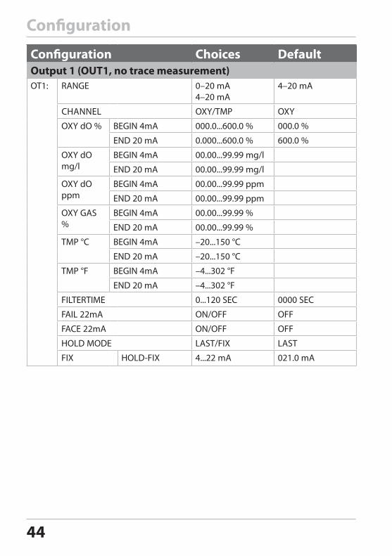
Configuration
Configuration Choices DefaultOutput 1 (OUT1, no trace measurement)OT1: RANGE 0–20 mA
4–20 mA4–20 mA
CHANNEL OXY/TMP OXY
OXY dO % BEGIN 4mA 000.0...600.0 % 000.0 %
END 20 mA 0.000...600.0 % 600.0 %
OXY dO mg/l
BEGIN 4mA 00.00...99.99 mg/l
END 20 mA 00.00...99.99 mg/l
OXY dO ppm
BEGIN 4mA 00.00...99.99 ppm
END 20 mA 00.00...99.99 ppm
OXY GAS %
BEGIN 4mA 00.00...99.99 %
END 20 mA 00.00...99.99 %
TMP °C BEGIN 4mA –20...150 °C
END 20 mA –20...150 °C
TMP °F BEGIN 4mA –4...302 °F
END 20 mA –4...302 °F
FILTERTIME 0...120 SEC 0000 SEC
FAIL 22mA ON/OFF OFF
FACE 22mA ON/OFF OFF
HOLD MODE LAST/FIX LAST
FIX HOLD-FIX 4...22 mA 021.0 mA
45
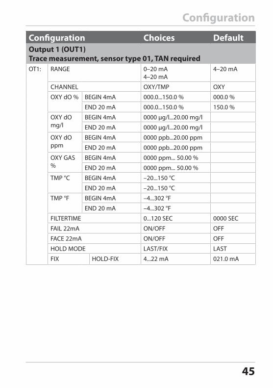
Configuration
Configuration Choices DefaultOutput 1 (OUT1)Trace measurement, sensor type 01, TAN requiredOT1: RANGE 0–20 mA
4–20 mA4–20 mA
CHANNEL OXY/TMP OXY
OXY dO % BEGIN 4mA 000.0...150.0 % 000.0 %
END 20 mA 000.0...150.0 % 150.0 %
OXY dO mg/l
BEGIN 4mA 0000 µg/l...20.00 mg/l
END 20 mA 0000 µg/l...20.00 mg/l
OXY dO ppm
BEGIN 4mA 0000 ppb...20.00 ppm
END 20 mA 0000 ppb...20.00 ppm
OXY GAS %
BEGIN 4mA 0000 ppm... 50.00 %
END 20 mA 0000 ppm... 50.00 %
TMP °C BEGIN 4mA –20...150 °C
END 20 mA –20...150 °C
TMP °F BEGIN 4mA –4...302 °F
END 20 mA –4...302 °F
FILTERTIME 0...120 SEC 0000 SEC
FAIL 22mA ON/OFF OFF
FACE 22mA ON/OFF OFF
HOLD MODE LAST/FIX LAST
FIX HOLD-FIX 4...22 mA 021.0 mA
46
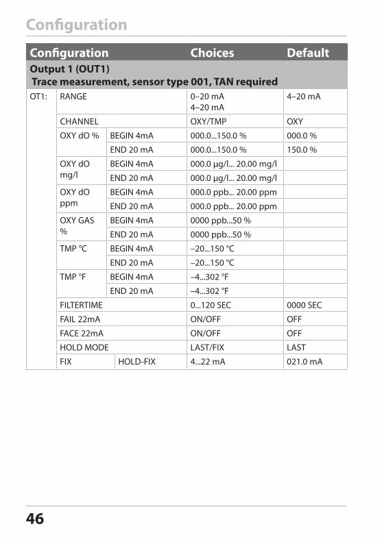
Configuration
Configuration Choices DefaultOutput 1 (OUT1) Trace measurement, sensor type 001, TAN requiredOT1: RANGE 0–20 mA
4–20 mA4–20 mA
CHANNEL OXY/TMP OXY
OXY dO % BEGIN 4mA 000.0...150.0 % 000.0 %
END 20 mA 000.0...150.0 % 150.0 %
OXY dO mg/l
BEGIN 4mA 000.0 μg/l... 20.00 mg/l
END 20 mA 000.0 μg/l... 20.00 mg/l
OXY dO ppm
BEGIN 4mA 000.0 ppb... 20.00 ppm
END 20 mA 000.0 ppb... 20.00 ppm
OXY GAS %
BEGIN 4mA 0000 ppb...50 %
END 20 mA 0000 ppb...50 %
TMP °C BEGIN 4mA –20...150 °C
END 20 mA –20...150 °C
TMP °F BEGIN 4mA –4...302 °F
END 20 mA –4...302 °F
FILTERTIME 0...120 SEC 0000 SEC
FAIL 22mA ON/OFF OFF
FACE 22mA ON/OFF OFF
HOLD MODE LAST/FIX LAST
FIX HOLD-FIX 4...22 mA 021.0 mA
47
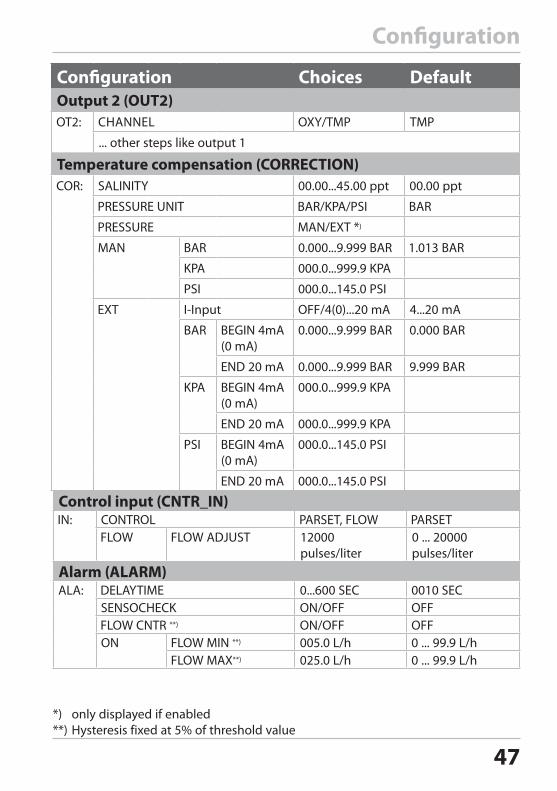
Configuration
Configuration Choices DefaultOutput 2 (OUT2)
... other steps like output 1
Temperature compensation (CORRECTION)
Control input (CNTR_IN)
12000 pulses/liter
0 ... 20000 pulses/liter
Alarm (ALARM)
*) only displayed if enabled**) Hysteresis fixed at 5% of threshold value
48
Configuration
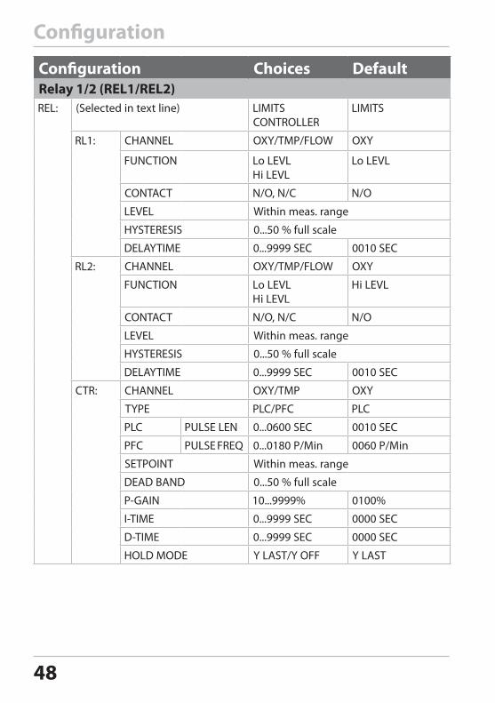
Configuration Choices DefaultRelay 1/2 (REL1/REL2)
(Selected in text line)
Within meas. range
0...50 % full scale
Within meas. range
0...50 % full scale
Within meas. range
0...50 % full scale
49
Configuration
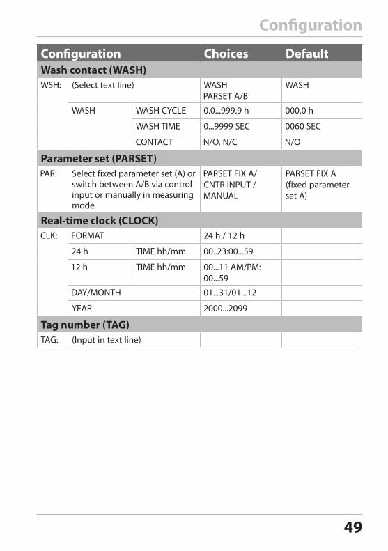
Configuration Choices DefaultWash contact (WASH)
(Select text line)
Parameter set (PARSET)Select fixed parameter set (A) or switch between A/B via control input or manually in measuring mode
PARSET FIX A(fixed parameter set A)
Real-time clock (CLOCK)
Tag number (TAG)(Input in text line)
50
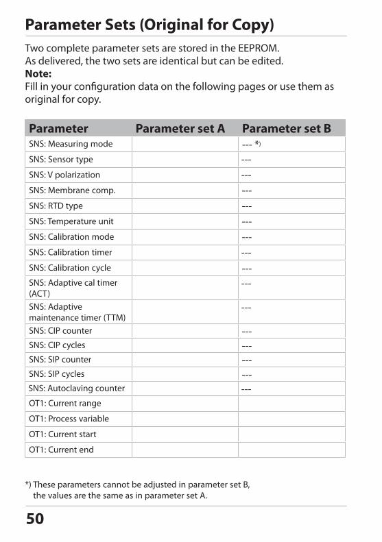
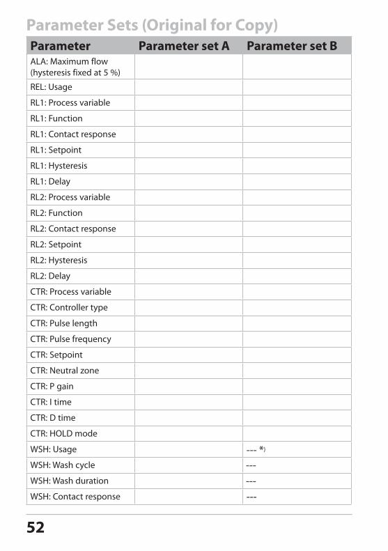
Parameter Sets (Original for Copy)Two complete parameter sets are stored in the EEPROM. As delivered, the two sets are identical but can be edited.Note:Fill in your configuration data on the following pages or use them as original for copy.
Parameter Parameter set A Parameter set BSNS: Measuring mode --- *)
SNS: Sensor type
SNS: V polarization
SNS: Membrane comp.
SNS: RTD type
SNS: Temperature unit
SNS: Calibration mode
SNS: Calibration timer
SNS: Calibration cycle
SNS: Adaptive cal timer (ACT)SNS: Adaptive maintenance timer (TTM)SNS: CIP counter
SNS: CIP cycles
SNS: SIP counter
SNS: SIP cycles
SNS: Autoclaving counter
OT1: Current range
OT1: Process variable
OT1: Current start
OT1: Current end
*) These parameters cannot be adjusted in parameter set B, the values are the same as in parameter set A.
51
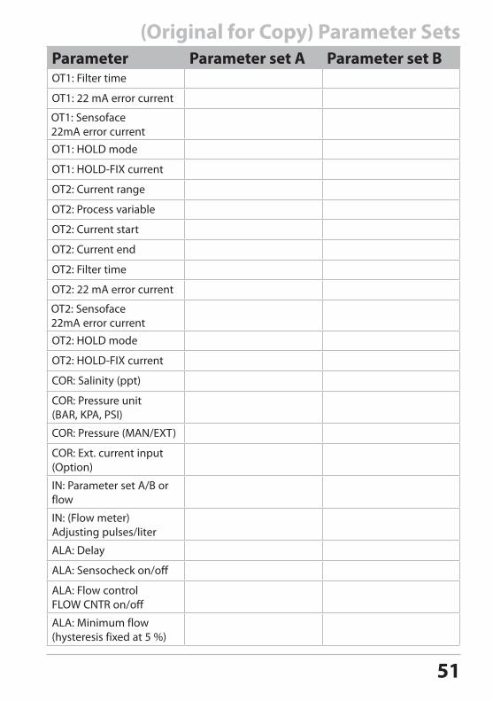
(Original for Copy) Parameter SetsParameter Parameter set A Parameter set BOT1: Filter time
OT1: 22 mA error current
OT1: Sensoface 22mA error currentOT1: HOLD mode
OT1: HOLD-FIX current
OT2: Current range
OT2: Process variable
OT2: Current start
OT2: Current end
OT2: Filter time
OT2: 22 mA error current
OT2: Sensoface 22mA error currentOT2: HOLD mode
OT2: HOLD-FIX current
COR: Salinity (ppt)
COR: Pressure unit (BAR, KPA, PSI)
COR: Pressure (MAN/EXT)
COR: Ext. current input(Option)
IN: Parameter set A/B or flow
IN: (Flow meter) Adjusting pulses/liter
ALA: Delay
ALA: Sensocheck on/off
ALA: Flow control FLOW CNTR on/off
ALA: Minimum flow (hysteresis fixed at 5 %)
52
Parameter Sets (Original for Copy)Parameter Parameter set A Parameter set BALA: Maximum flow (hysteresis fixed at 5 %)
REL: Usage
RL1: Process variable
RL1: Function
RL1: Contact response
RL1: Setpoint
RL1: Hysteresis
RL1: Delay
RL2: Process variable
RL2: Function
RL2: Contact response
RL2: Setpoint
RL2: Hysteresis
RL2: Delay
CTR: Process variable
CTR: Controller type
CTR: Pulse length
CTR: Pulse frequency
CTR: Setpoint
CTR: Neutral zone
CTR: P gain
CTR: I time
CTR: D time
CTR: HOLD mode
WSH: Usage
WSH: Wash cycle
WSH: Wash duration
WSH: Contact response
53
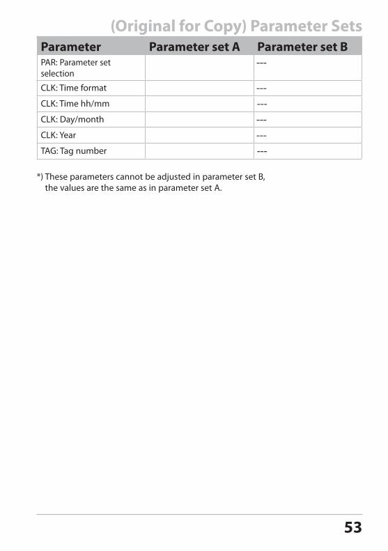
Parameter Parameter set A Parameter set BPAR: Parameter set selection
CLK: Time format
CLK: Time hh/mm
CLK: Day/month
CLK: Year
TAG: Tag number
*) These parameters cannot be adjusted in parameter set B, the values are the same as in parameter set A.
(Original for Copy) Parameter Sets
54
1
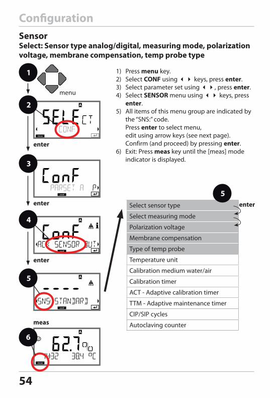
ConfigurationSensorSelect: Sensor type analog/digital, measuring mode, polarization voltage, membrane compensation, temp probe type
1) Press menu key.2) Select CONF using keys, press enter.3) Select parameter set using , press enter.4) Select SENSOR menu using keys, press
enter. 5) All items of this menu group are indicated by
the “SNS:” code. Press enter to select menu, edit using arrow keys (see next page). Confirm (and proceed) by pressing enter.
6) Exit: Press meas key until the [meas] mode indicator is displayed.
2
3
4
Select sensor type
Select measuring mode
Polarization voltage
Membrane compensation
Type of temp probe
Temperature unit
Calibration medium water/air
Calibration timer
ACT - Adaptive calibration timer
TTM - Adaptive maintenance timer
CIP/SIP cycles
Autoclaving counter
5enter
enter
6
enter
5
enter
meas
55
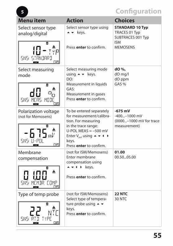
ConfigurationMenu item Action ChoicesSelect sensor typeanalog/digital
Select sensor type using keys.
Press enter to confirm.
Select measuring mode
Select measuring mode using keys.DO: Measurement in liquidsGAS:Measurement in gasesPress enter to confirm.
Polarization voltage (not for Memosens)
To be entered separately for measurement/calibra-tion. For measuring in the trace range: U-POL MEAS = –500 mVEnter Vpol using keys.Press enter to confirm.
-675 mV-400...–1000 mV(0000...–1000 mV for trace measurement)
Membrane compensation
(not for ISM/Memosens)Enter membrane compensation using keys.
Press enter to confirm.
Type of temp probe (not for ISM/Memosens)Select type of tempera-ture probe using keys.Press enter to confirm.
5
56
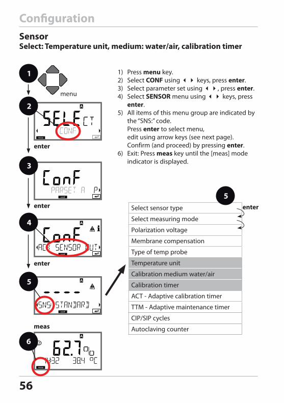
ConfigurationSensorSelect: Temperature unit, medium: water/air, calibration timer
1 1) Press menu key.2) Select CONF using keys, press enter.3) Select parameter set using , press enter.4) Select SENSOR menu using keys, press
enter. 5) All items of this menu group are indicated by
the “SNS:” code. Press enter to select menu, edit using arrow keys (see next page). Confirm (and proceed) by pressing enter.
6) Exit: Press meas key until the [meas] mode indicator is displayed.
2
3
4
Select sensor type
Select measuring mode
Polarization voltage
Membrane compensation
Type of temp probe
Temperature unit
Calibration medium water/air
Calibration timer
ACT - Adaptive calibration timer
TTM - Adaptive maintenance timer
CIP/SIP cycles
Autoclaving counter
5enter
enter
6
enter
5
enter
meas
57
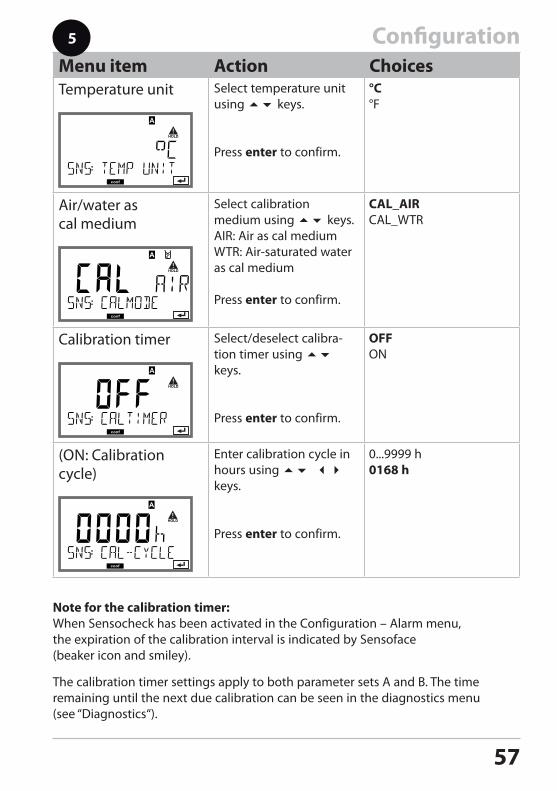
ConfigurationMenu item Action ChoicesTemperature unit Select temperature unit
using keys.
Press enter to confirm.
Air/water as cal medium
Select calibration medium using keys.AIR: Air as cal mediumWTR: Air-saturated water as cal medium
Press enter to confirm.
Calibration timer Select/deselect calibra-tion timer using keys.
Press enter to confirm.
(ON: Calibration cycle)
Enter calibration cycle in hours using keys.
Press enter to confirm.
5
Note for the calibration timer:When Sensocheck has been activated in the Configuration – Alarm menu, the expiration of the calibration interval is indicated by Sensoface (beaker icon and smiley).
The calibration timer settings apply to both parameter sets A and B. The time remaining until the next due calibration can be seen in the diagnostics menu (see “Diagnostics“).
58
1
2
4
enter
6
enter
5
enter
meas
3
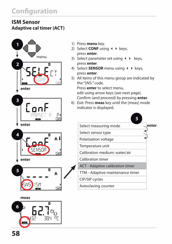
ConfigurationISM SensorAdaptive cal timer (ACT)
1) Press menu key.2) Select CONF using keys,
press enter.3) Select parameter set using keys,
press enter.4) Select SENSOR menu using keys,
press enter. 5) All items of this menu group are indicated by
the “SNS:” code. Press enter to select menu, edit using arrow keys (see next page). Confirm (and proceed) by pressing enter.
6) Exit: Press meas key until the [meas] mode indicator is displayed.
Select measuring mode
Select sensor type
Polarization voltage
Temperature unit
Calibration medium: water/air
Calibration timer
ACT - Adaptive calibration timer
TTM - Adaptive maintenance timer
CIP/SIP cycles
Autoclaving counter
5enter
59
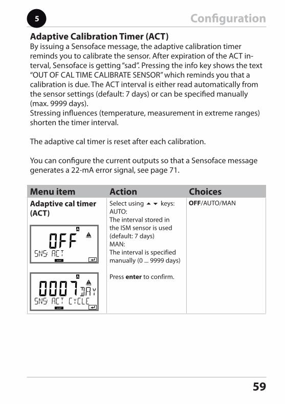
ConfigurationAdaptive Calibration Timer (ACT)By issuing a Sensoface message, the adaptive calibration timer reminds you to calibrate the sensor. After expiration of the ACT in-terval, Sensoface is getting “sad”. Pressing the info key shows the text “OUT OF CAL TIME CALIBRATE SENSOR” which reminds you that a calibration is due. The ACT interval is either read automatically from the sensor settings (default: 7 days) or can be specified manually (max. 9999 days).Stressing influences (temperature, measurement in extreme ranges) shorten the timer interval.
The adaptive cal timer is reset after each calibration.
You can configure the current outputs so that a Sensoface message generates a 22-mA error signal, see page 71.
Menu item Action ChoicesAdaptive cal timer (ACT)
Select using keys: AUTO:The interval stored in the ISM sensor is used (default: 7 days)MAN:The interval is specified manually (0 ... 9999 days)
Press enter to confirm.
60
1
2
4
enter
6
enter
5
enter
meas
3
1) Press menu key.2) Select CONF using keys,
press enter.3) Select parameter set using keys,
press enter.4) Select SENSOR menu using keys,
press enter. 5) All items of this menu group are indicated by
the “SNS:” code. Press enter to select menu, edit using arrow keys (see next page). Confirm (and proceed) by pressing enter.
6) Exit: Press meas key until the [meas] mode indicator is displayed.
Select measuring mode
Select sensor type
Polarization voltage
Temperature unit
Calibration medium: water/air
Calibration timer
ACT - Adaptive calibration timer
TTM - Adaptive maintenance timer
CIP/SIP cycles
Autoclaving counter
5enter
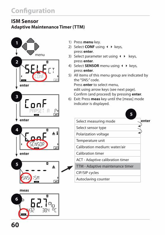
ConfigurationISM SensorAdaptive Maintenance Timer (TTM)
61
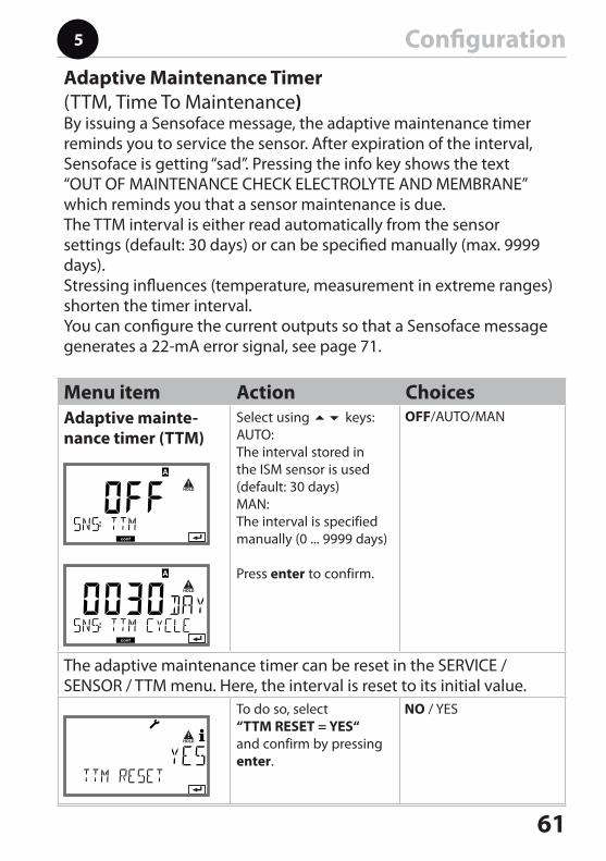
ConfigurationAdaptive Maintenance Timer (TTM, Time To Maintenance)By issuing a Sensoface message, the adaptive maintenance timer reminds you to service the sensor. After expiration of the interval, Sensoface is getting “sad”. Pressing the info key shows the text “OUT OF MAINTENANCE CHECK ELECTROLYTE AND MEMBRANE” which reminds you that a sensor maintenance is due. The TTM interval is either read automatically from the sensor settings (default: 30 days) or can be specified manually (max. 9999 days).Stressing influences (temperature, measurement in extreme ranges) shorten the timer interval.You can configure the current outputs so that a Sensoface message generates a 22-mA error signal, see page 71.
Menu item Action ChoicesAdaptive mainte-nance timer (TTM)
Select using keys: AUTO:The interval stored in the ISM sensor is used (default: 30 days)MAN:The interval is specified manually (0 ... 9999 days)
Press enter to confirm.
The adaptive maintenance timer can be reset in the SERVICE / SENSOR / TTM menu. Here, the interval is reset to its initial value.
To do so, select “TTM RESET = YES“ and confirm by pressing enter.
62
Configuration
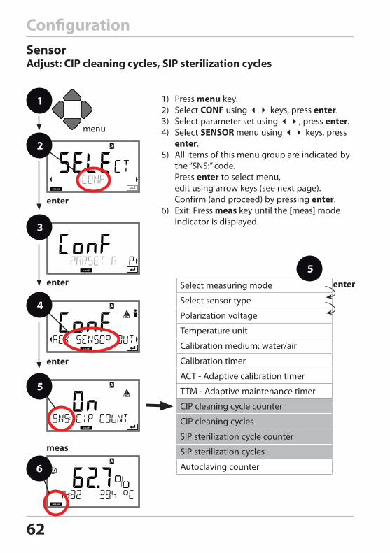
1 1) Press menu key.2) Select CONF using keys, press enter.3) Select parameter set using , press enter.4) Select SENSOR menu using keys, press
enter. 5) All items of this menu group are indicated by
the “SNS:” code. Press enter to select menu, edit using arrow keys (see next page). Confirm (and proceed) by pressing enter.
6) Exit: Press meas key until the [meas] mode indicator is displayed.
2
3
4
enter
6
enter
5
enter
meas
SensorAdjust: CIP cleaning cycles, SIP sterilization cycles
Select measuring mode
Select sensor type
Polarization voltage
Temperature unit
Calibration medium: water/air
Calibration timer
ACT - Adaptive calibration timer
TTM - Adaptive maintenance timer
CIP cleaning cycle counter
CIP cleaning cycles
SIP sterilization cycle counter
SIP sterilization cycles
Autoclaving counter
5enter
63
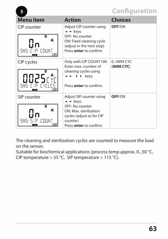
ConfigurationMenu item Action ChoicesCIP counter Adjust CIP counter using
keys:OFF: No counterON: Fixed cleaning cycle (adjust in the next step)Press enter to confirm.
OFF/ON
CIP cycles Only with CIP COUNT ON:Enter max. number of cleaning cycles using keys.
Press enter to confirm.
0...9999 CYC(0000 CYC)
SIP counter Adjust SIP counter using keys:OFF: No counterON: Max. sterilization cycles (adjust as for CIP counter)Press enter to confirm.
OFF/ON
5
The cleaning and sterilization cycles are counted to measure the load on the sensor. Suitable for biochemical applications (process temp approx. 0...50 °C, CIP temperature > 55 °C, SIP temperature > 115 °C).
64
1
2
4
enter
6
enter
5
enter
meas
3
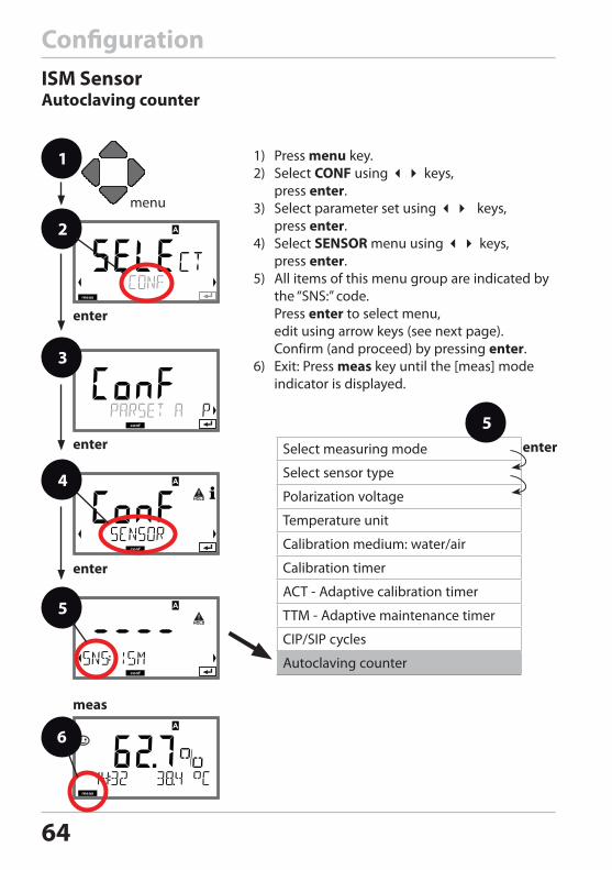
ConfigurationISM SensorAutoclaving counter
1) Press menu key.2) Select CONF using keys,
press enter.3) Select parameter set using keys,
press enter.4) Select SENSOR menu using keys,
press enter. 5) All items of this menu group are indicated by
the “SNS:” code. Press enter to select menu, edit using arrow keys (see next page). Confirm (and proceed) by pressing enter.
6) Exit: Press meas key until the [meas] mode indicator is displayed.
Select measuring mode
Select sensor type
Polarization voltage
Temperature unit
Calibration medium: water/air
Calibration timer
ACT - Adaptive calibration timer
TTM - Adaptive maintenance timer
CIP/SIP cycles
Autoclaving counter
5enter
65
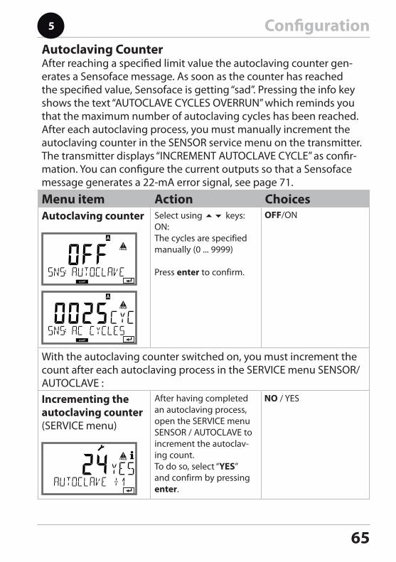
ConfigurationAutoclaving CounterAfter reaching a specified limit value the autoclaving counter gen-erates a Sensoface message. As soon as the counter has reached the specified value, Sensoface is getting “sad”. Pressing the info key shows the text “AUTOCLAVE CYCLES OVERRUN” which reminds you that the maximum number of autoclaving cycles has been reached. After each autoclaving process, you must manually increment the autoclaving counter in the SENSOR service menu on the transmitter. The transmitter displays “INCREMENT AUTOCLAVE CYCLE” as confir-mation. You can configure the current outputs so that a Sensoface message generates a 22-mA error signal, see page 71.
Menu item Action ChoicesAutoclaving counter Select using keys:
ON:The cycles are specified manually (0 ... 9999)
Press enter to confirm.
With the autoclaving counter switched on, you must increment the count after each autoclaving process in the SERVICE menu SENSOR/AUTOCLAVE : Incrementing the autoclaving counter(SERVICE menu)
After having completed an autoclaving process, open the SERVICE menu SENSOR / AUTOCLAVE to increment the autoclav-ing count. To do so, select “YES” and confirm by pressing enter.
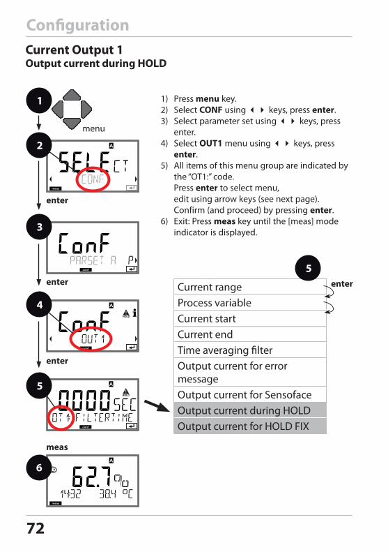
66
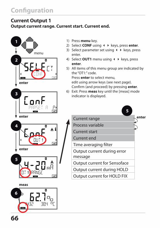
Current rangeProcess variableCurrent startCurrent endTime averaging filterOutput current during error messageOutput current for SensofaceOutput current during HOLDOutput current for HOLD FIX
ConfigurationCurrent Output 1Output current range. Current start. Current end.
1 1) Press menu key.2) Select CONF using keys, press enter.3) Select parameter set using keys, press
enter.4) Select OUT1 menu using keys, press
enter. 5) All items of this menu group are indicated by
the “OT1:” code. Press enter to select menu, edit using arrow keys (see next page). Confirm (and proceed) by pressing enter.
6) Exit: Press meas key until the [meas] mode indicator is displayed.
2
3
4
5enter
enter
6
enter
5
enter
meas
67
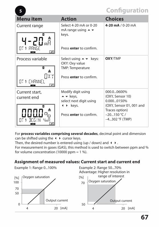
ConfigurationMenu item Action ChoicesCurrent range Select 4-20 mA or 0-20
mA range using keys.
Press enter to confirm.
Process variable Select using keys:OXY: Oxy valueTMP: Temperature
Press enter to confirm.
Current start, current end
Modify digit using keys, select next digit using keys.
Press enter to confirm.
000.0...0600% (OXY, Sensor 10)0.000...0150% (OXY, Sensor 01, 001 and Traces option) –20...150 °C / –4...302 °F (TMP)
For process variables comprising several decades, decimal point and dimension can be shifted using the cursor keys. Then, the desired number is entered using (up / down) and . For measurement in gases (GAS), this method is used to switch between ppm and % for volume concentration (10000 ppm = 1 %).
5
Example 2: Range 50...70% Advantage: Higher resolution in
range of interest
Assignment of measured values: Current start and current end
Output current
[%]
20 4
100
0
[%]
20 4
70
50[mA]
Example 1: Range 0...100%
[mA]
Output current
5070
Oxygen saturationOxygen saturation
68
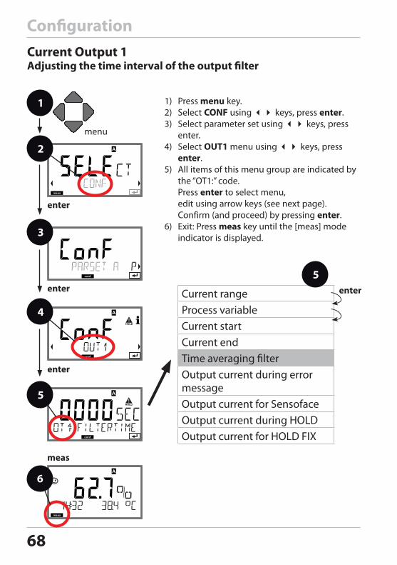
ConfigurationCurrent Output 1Adjusting the time interval of the output filter
Current rangeProcess variableCurrent startCurrent endTime averaging filterOutput current during error messageOutput current for SensofaceOutput current during HOLDOutput current for HOLD FIX
1 1) Press menu key.2) Select CONF using keys, press enter.3) Select parameter set using keys, press
enter.4) Select OUT1 menu using keys, press
enter. 5) All items of this menu group are indicated by
the “OT1:” code. Press enter to select menu, edit using arrow keys (see next page). Confirm (and proceed) by pressing enter.
6) Exit: Press meas key until the [meas] mode indicator is displayed.
2
3
4
5enter
enter
6
enter
5
enter
meas
69
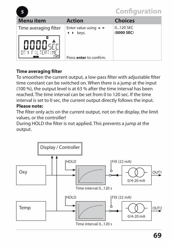
ConfigurationMenu item Action ChoicesTime averaging filter Enter value using
keys.
Press enter to confirm.
5
Time averaging filterTo smoothen the current output, a low-pass filter with adjustable filter time constant can be switched on. When there is a jump at the input (100 %), the output level is at 63 % after the time interval has been reached. The time interval can be set from 0 to 120 sec. If the time interval is set to 0 sec, the current output directly follows the input.Please note: The filter only acts on the current output, not on the display, the limit values, or the controller!During HOLD the filter is not applied. This prevents a jump at the output.
Time interval 0...120 s
Oxy
Time interval 0...120 s
Temp
Display / Controller
70
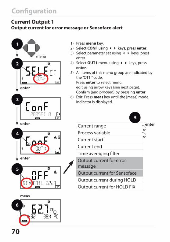
Current rangeProcess variableCurrent startCurrent endTime averaging filterOutput current for error messageOutput current for SensofaceOutput current during HOLDOutput current for HOLD FIX
1 1) Press menu key.2) Select CONF using keys, press enter.3) Select parameter set using keys, press
enter.4) Select OUT1 menu using keys, press
enter. 5) All items of this menu group are indicated by
the “OT1:” code. Press enter to select menu, edit using arrow keys (see next page). Confirm (and proceed) by pressing enter.
6) Exit: Press meas key until the [meas] mode indicator is displayed.
2
3
4
5enter
enter
6
enter
enter
meas
ConfigurationCurrent Output 1Output current for error message or Sensoface alert
5
71
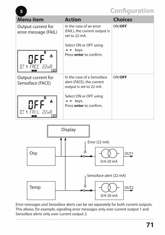
ConfigurationMenu item Action ChoicesOutput current for error message (FAIL)
In the case of an error (FAIL), the current output is set to 22 mA.
Select ON or OFF using keys.Press enter to confirm.
Output current for Sensoface (FACE)
In the case of a Sensoface alert (FACE), the current output is set to 22 mA.
Select ON or OFF using keys.Press enter to confirm.
Oxy
Temp
Display
Error (22 mA)
Sensoface alert (22 mA)
Error messages and Sensoface alerts can be set separately for both current outputs. This allows, for example, signaling error messages only over current output 1 and Sensoface alerts only over current output 2.
72
Configuration
1 1) Press menu key.2) Select CONF using keys, press enter.3) Select parameter set using keys, press
enter.4) Select OUT1 menu using keys, press
enter. 5) All items of this menu group are indicated by
the “OT1:” code. Press enter to select menu, edit using arrow keys (see next page). Confirm (and proceed) by pressing enter.
6) Exit: Press meas key until the [meas] mode indicator is displayed.
2
3
4
enter
6
enter
5
enter
meas
Current rangeProcess variableCurrent startCurrent endTime averaging filterOutput current for error messageOutput current for SensofaceOutput current during HOLDOutput current for HOLD FIX
Current Output 1Output current during HOLD
73
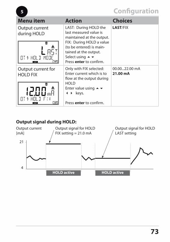
ConfigurationMenu item Action ChoicesOutput current during HOLD
LAST: During HOLD the last measured value is maintained at the output.FIX: During HOLD a value (to be entered) is main-tained at the output.Select using Press enter to confirm.
Output current for HOLD FIX
Only with FIX selected:Enter current which is to flow at the output during HOLDEnter value using keys.
Press enter to confirm.
HOLD active
21
4HOLD active
Output current[mA]
Output signal for HOLDFIX setting = 21.0 mA
Output signal for HOLDLAST setting
Output signal during HOLD:
5
74
Configuration
Current rangeProcess variableCurrent startCurrent endTime averaging filterOutput current during error messageOutput current for SensofaceOutput current during HOLDOutput current for HOLD FIX
1 1) Press menu key.2) Select CONF using keys, press enter.3) Select parameter set using keys, press
enter.4) Select OUT2 menu using keys, press
enter. 5) All items of this menu group are indicated by
the “OT2:” code. Press enter to select menu, edit using arrow keys (see next page). Confirm (and proceed) by pressing enter.
6) Exit: Press meas key until the [meas] mode indicator is displayed.
2
3
4
5enter
enter
6
enter
5
enter
meas
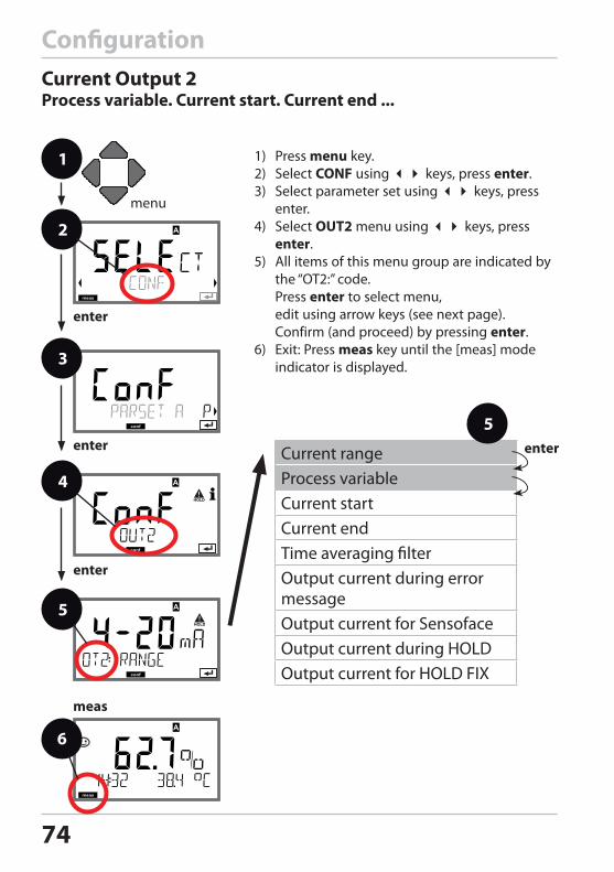
Current Output 2Process variable. Current start. Current end ...
75
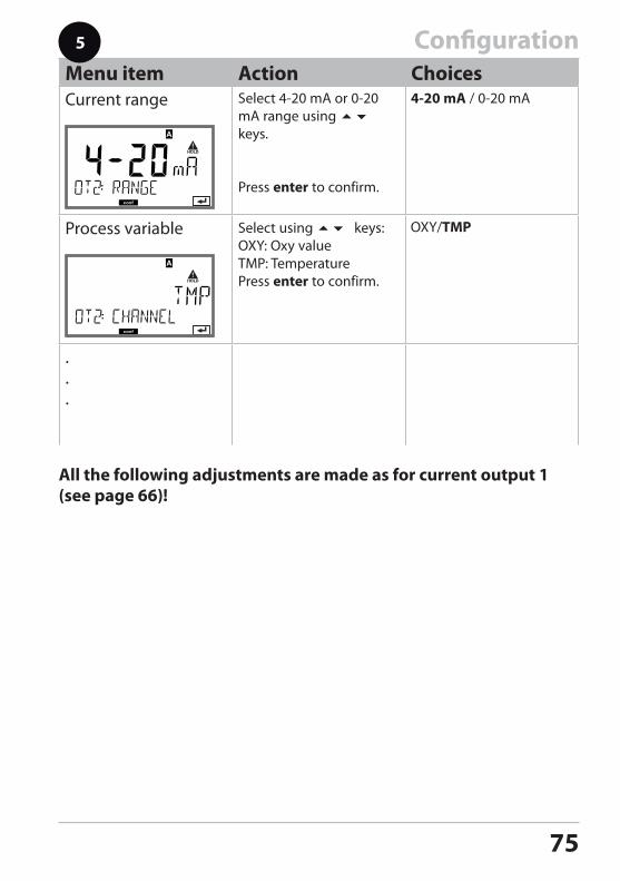
ConfigurationMenu item Action ChoicesCurrent range Select 4-20 mA or 0-20
mA range using keys.
Press enter to confirm.
Process variable Select using keys:OXY: Oxy valueTMP: TemperaturePress enter to confirm.
.
.
.
All the following adjustments are made as for current output 1 (see page 66)!
5
76
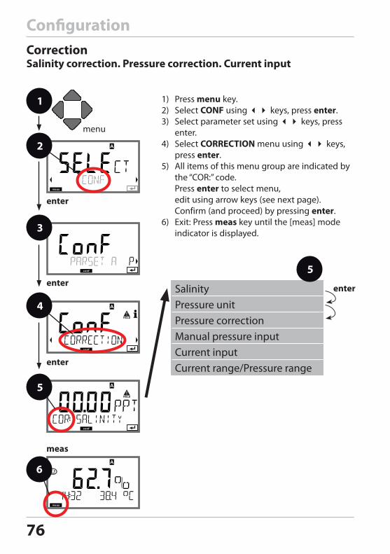
ConfigurationCorrectionSalinity correction. Pressure correction. Current input
1 1) Press menu key.2) Select CONF using keys, press enter.3) Select parameter set using keys, press
enter.4) Select CORRECTION menu using keys,
press enter. 5) All items of this menu group are indicated by
the “COR:” code. Press enter to select menu, edit using arrow keys (see next page). Confirm (and proceed) by pressing enter.
6) Exit: Press meas key until the [meas] mode indicator is displayed.
2
3
4
enter
6
enter
5
enter
meas
enterSalinityPressure unitPressure correctionManual pressure inputCurrent inputCurrent range/Pressure range
5
77
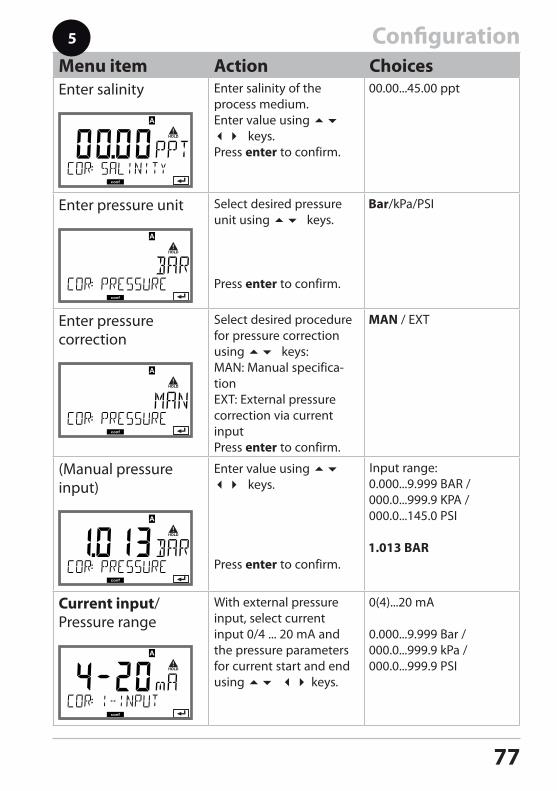
ConfigurationMenu item Action ChoicesEnter salinity Enter salinity of the
process medium.Enter value using keys.Press enter to confirm.
Enter pressure unit Select desired pressure unit using keys.
Press enter to confirm.
Enter pressure correction
Select desired procedure for pressure correction using keys:MAN: Manual specifica-tionEXT: External pressure correction via current inputPress enter to confirm.
(Manual pressure input)
Enter value using keys.
Press enter to confirm.
Input range:
Current input/Pressure range
With external pressure input, select current input 0/4 ... 20 mA and the pressure parameters for current start and end using keys.
5
78
1
2
3
6
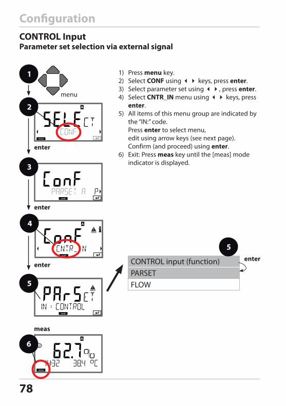
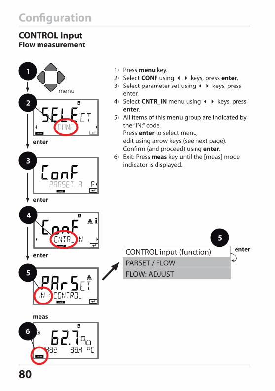
ConfigurationCONTROL InputParameter set selection via external signal
1) Press menu key.2) Select CONF using keys, press enter.3) Select parameter set using , press enter.4) Select CNTR_IN menu using keys, press
enter. 5) All items of this menu group are indicated by
the “IN:” code. Press enter to select menu, edit using arrow keys (see next page). Confirm (and proceed) using enter.
6) Exit: Press meas key until the [meas] mode indicator is displayed.
CONTROL input (function)PARSETFLOW
79
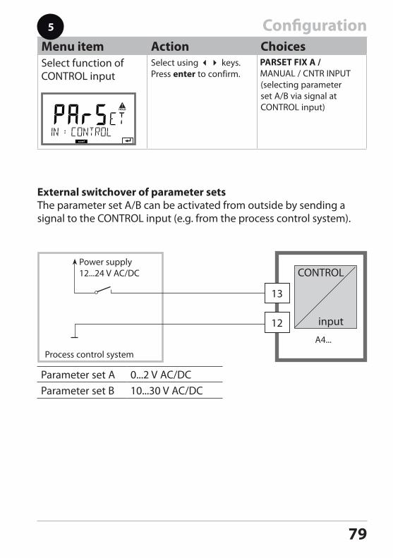
Menu item Action ChoicesSelect function of CONTROL input
Select using keys. Press enter to confirm.
(selecting parameter set A/B via signal at CONTROL input)
Parameter set A 0...2 V AC/DCParameter set B 10...30 V AC/DC
Process control system
Power supply12...24 V AC/DC
A4...
CONTROL input
External switchover of parameter setsThe parameter set A/B can be activated from outside by sending a signal to the CONTROL input (e.g. from the process control system).
Configuration5
80
Configuration
1 1) Press menu key.2) Select CONF using keys, press enter.3) Select parameter set using keys, press
enter.4) Select CNTR_IN menu using keys, press
enter. 5) All items of this menu group are indicated by
the “IN:” code. Press enter to select menu, edit using arrow keys (see next page). Confirm (and proceed) using enter.
6) Exit: Press meas key until the [meas] mode indicator is displayed.
2
enter
enter
5
4
3
enter
CONTROL input (function)PARSET / FLOWFLOW: ADJUST
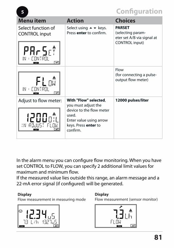
CONTROL InputFlow measurement
81
In the alarm menu you can configure flow monitoring. When you have set CONTROL to FLOW, you can specify 2 additional limit values for maximum and minimum flow. If the measured value lies outside this range, an alarm message and a 22-mA error signal (if configured) will be generated.
ConfigurationMenu item Action ChoicesSelect function of CONTROL input
Select using keys. Press enter to confirm.
PARSET(selecting param-eter set A/B via signal at CONTROL input)
Flow (for connecting a pulse-output flow meter)
Adjust to flow meter: With "Flow" selected, you must adjust the device to the flow meter used. Enter value using arrow keys. Press enter to confirm.
12000 pulses/liter
5
Display Flow measurement in measuring mode
Display Flow measurement (sensor monitor)
82
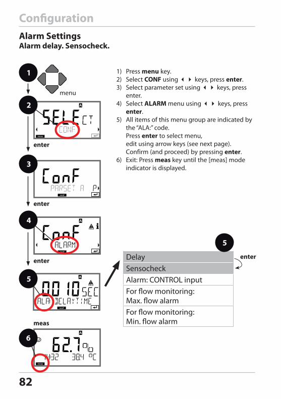
ConfigurationAlarm SettingsAlarm delay. Sensocheck.
1 1) Press menu key.2) Select CONF using keys, press enter.3) Select parameter set using keys, press
enter.4) Select ALARM menu using keys, press
enter. 5) All items of this menu group are indicated by
the “ALA:” code. Press enter to select menu, edit using arrow keys (see next page). Confirm (and proceed) by pressing enter.
6) Exit: Press meas key until the [meas] mode indicator is displayed.
2
3
4
enter
6
enter
enter
meas
5
enterDelaySensocheckAlarm: CONTROL inputFor flow monitoring: Max. flow alarmFor flow monitoring: Min. flow alarm
5
83
17
18
Alarm
R3
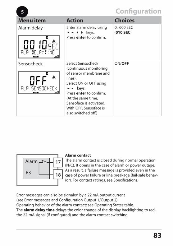
ConfigurationMenu item Action ChoicesAlarm delay Enter alarm delay using
keys.Press enter to confirm.
Sensocheck Select Sensocheck (continuous monitoring of sensor membrane and lines).Select ON or OFF using keys.Press enter to confirm.(At the same time, Sensoface is activated. With OFF, Sensoface is also switched off.)
5
Alarm contactThe alarm contact is closed during normal operation (N/C). It opens in the case of alarm or power outage. As a result, a failure message is provided even in the case of power failure or line breakage (fail-safe behav-ior). For contact ratings, see Specifications.
Error messages can also be signaled by a 22 mA output current (see Error messages and Configuration Output 1/Output 2).Operating behavior of the alarm contact: see Operating States table.The alarm delay time delays the color change of the display backlighting to red, the 22-mA signal (if configured) and the alarm contact switching.
84
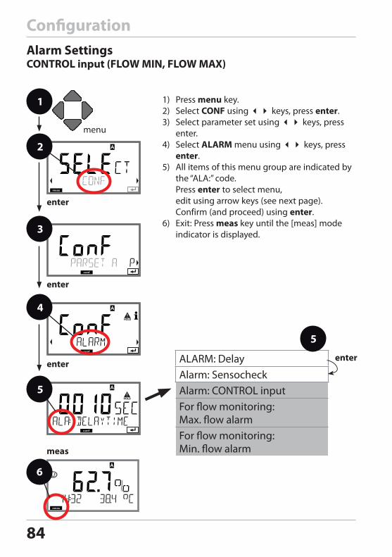
ConfigurationAlarm SettingsCONTROL input (FLOW MIN, FLOW MAX)
1 1) Press menu key.2) Select CONF using keys, press enter.3) Select parameter set using keys, press
enter.4) Select ALARM menu using keys, press
enter. 5) All items of this menu group are indicated by
the “ALA:” code. Press enter to select menu, edit using arrow keys (see next page). Confirm (and proceed) using enter.
6) Exit: Press meas key until the [meas] mode indicator is displayed.
2
4
enter
6
enter
5
enter
meas
3
ALARM: DelayAlarm: SensocheckAlarm: CONTROL inputFor flow monitoring: Max. flow alarmFor flow monitoring: Min. flow alarm
enter
5
85
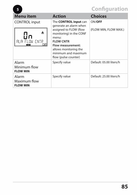
ConfigurationMenu item Action ChoicesCONTROL input The CONTROL input can
generate an alarm when assigned to FLOW (flow monitoring) in the CONF menu: FLOW CNTR Flow measurement: allows monitoring the minimum and maximum flow (pulse counter)
AlarmMinimum flowFLOW MIN
Specify value Default: 05.00 liters/h
AlarmMaximum flowFLOW MIN
Specify value Default: 25.00 liters/h
5
86
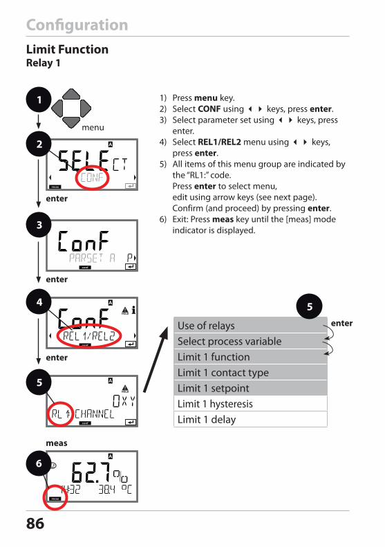
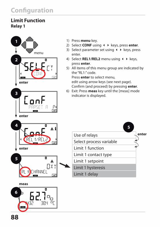
ConfigurationLimit FunctionRelay 1
1 1) Press menu key.2) Select CONF using keys, press enter.3) Select parameter set using keys, press
enter.4) Select REL1/REL2 menu using keys,
press enter. 5) All items of this menu group are indicated by
the “RL1:” code. Press enter to select menu, edit using arrow keys (see next page). Confirm (and proceed) by pressing enter.
6) Exit: Press meas key until the [meas] mode indicator is displayed.
2
3
4
enter
6
enter
5
enter
meas
Use of relaysSelect process variableLimit 1 functionLimit 1 contact type Limit 1 setpointLimit 1 hysteresisLimit 1 delay
enter
5
87
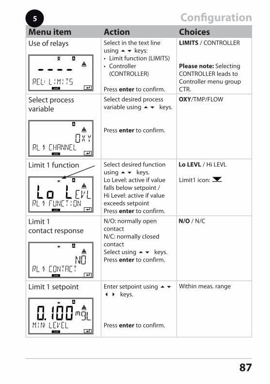
ConfigurationMenu item Action ChoicesUse of relays Select in the text line
using keys:• Limit function (LIMITS)• Controller
(CONTROLLER)
Press enter to confirm.
LIMITS / CONTROLLER
Please note: Selecting CONTROLLER leads to Controller menu group CTR.
Select process variable
Select desired process variable using keys.
Press enter to confirm.
Limit 1 function Select desired function using keys.Lo Level: active if value falls below setpoint / Hi Level: active if value exceeds setpointPress enter to confirm.
Limit1 icon:
Limit 1 contact response
N/O: normally open contactN/C: normally closed contactSelect using keys.Press enter to confirm.
Limit 1 setpoint Enter setpoint using keys.
Press enter to confirm.
Within meas. range
5
88
Configuration
1 1) Press menu key.2) Select CONF using keys, press enter.3) Select parameter set using keys, press
enter.4) Select REL1/REL2 menu using keys,
press enter. 5) All items of this menu group are indicated by
the “RL1:” code. Press enter to select menu, edit using arrow keys (see next page). Confirm (and proceed) by pressing enter.
6) Exit: Press meas key until the [meas] mode indicator is displayed.
2
3
4
enter
6
enter
5
enter
meas
Use of relaysSelect process variableLimit 1 functionLimit 1 contact type Limit 1 setpointLimit 1 hysteresisLimit 1 delay
enter
5
Limit FunctionRelay 1
89
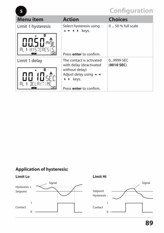
ConfigurationMenu item Action ChoicesLimit 1 hysteresis Select hysteresis using
keys.
Press enter to confirm.
0 ... 50 % full scale
Limit 1 delay The contact is activated with delay (deactivated without delay)Adjust delay using keys.
Press enter to confirm.
Limit Lo
Hysteresis +Setpoint
Contact0
1
Signal
Limit Hi
Hysteresis -
Signal
Setpoint
Contact0
1
5
Application of hysteresis:
90
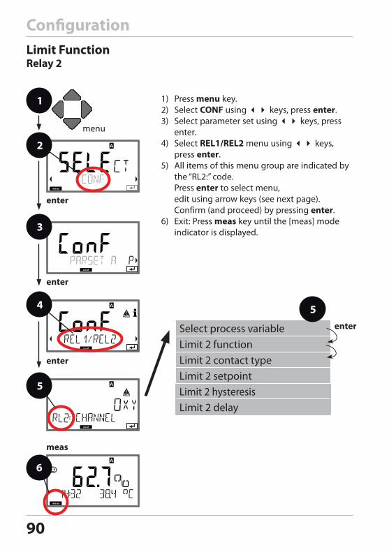
Limit FunctionRelay 2
Configuration
1 1) Press menu key.2) Select CONF using keys, press enter.3) Select parameter set using keys, press
enter.4) Select REL1/REL2 menu using keys,
press enter. 5) All items of this menu group are indicated by
the “RL2:” code. Press enter to select menu, edit using arrow keys (see next page). Confirm (and proceed) by pressing enter.
6) Exit: Press meas key until the [meas] mode indicator is displayed.
2
3
4
enter
6
enter
5
enter
meas
Select process variableLimit 2 functionLimit 2 contact typeLimit 2 setpointLimit 2 hysteresisLimit 2 delay
enter
5
91
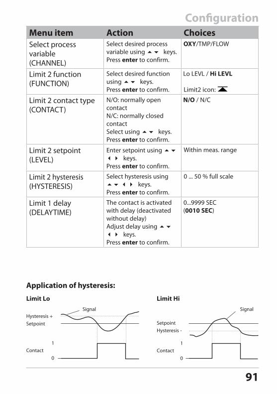
ConfigurationMenu item Action ChoicesSelect process variable(CHANNEL)
Select desired process variable using keys.Press enter to confirm.
Limit 2 function(FUNCTION)
Select desired function using keys.Press enter to confirm. Limit2 icon:
Limit 2 contact type (CONTACT)
N/O: normally open contactN/C: normally closed contactSelect using keys.Press enter to confirm.
Limit 2 setpoint (LEVEL)
Enter setpoint using keys.Press enter to confirm.
Within meas. range
Limit 2 hysteresis(HYSTERESIS)
Select hysteresis using keys.Press enter to confirm.
0 ... 50 % full scale
Limit 1 delay(DELAYTIME)
The contact is activated with delay (deactivated without delay)Adjust delay using keys.Press enter to confirm.
Limit Lo
Hysteresis +Setpoint
Contact0
1
Signal
Limit Hi
Hysteresis -
Signal
Setpoint
Contact0
1
Application of hysteresis:

92
93
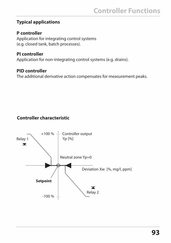
Controller Functions
Setpoint
Controller output Yp [%]
+100 %
-100 %
Deviation Xw [%, mg/l, ppm]
Neutral zone Yp=0
Relay 1
Relay 2
Typical applications
P controller Application for integrating control systems (e.g. closed tank, batch processes).
PI controllerApplication for non-integrating control systems (e.g. drains).
PID controller The additional derivative action compensates for measurement peaks.
Controller characteristic
94
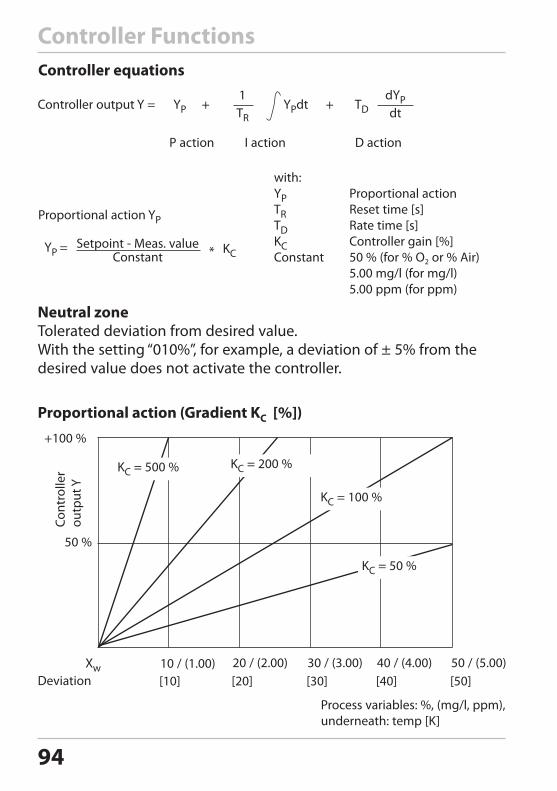
Controller Functions
Proportional action YP
Setpoint - Meas. valueConstant
YP = *
with:YP Proportional actionTR Reset time [s]TD Rate time [s]KC Controller gain [%]Constant 50 % (for % O2 or % Air) 5.00 mg/l (for mg/l) 5.00 ppm (for ppm)
Controller equations
KC
Neutral zoneTolerated deviation from desired value. With the setting “010%”, for example, a deviation of ± 5% from the desired value does not activate the controller.
+100 %
50 %
Cont
rolle
r ou
tput
Y
KC = 500 % KC = 200 %
KC = 100 %
KC = 50 %
Proportional action (Gradient KC [%])
Xw
Process variables: %, (mg/l, ppm),underneath: temp [K]
Deviation [10] [20] [30] [40] [50]10 / (1.00) 20 / (2.00) 30 / (3.00) 40 / (4.00) 50 / (5.00)
Controller output Y =
I action D action
dYPdt
1TR
P action
YP + YPdt + TD
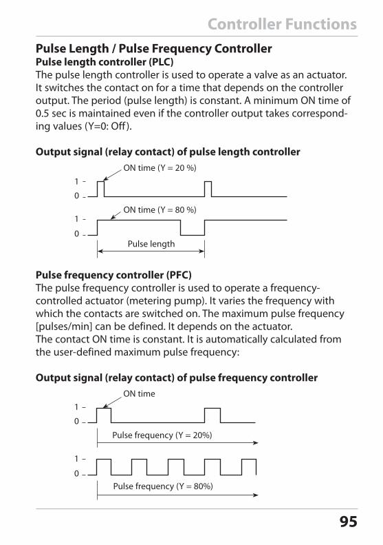
95
Controller FunctionsPulse Length / Pulse Frequency ControllerPulse length controller (PLC)The pulse length controller is used to operate a valve as an actuator. It switches the contact on for a time that depends on the controller output. The period (pulse length) is constant. A minimum ON time of 0.5 sec is maintained even if the controller output takes correspond-ing values (Y=0: Off ).
Output signal (relay contact) of pulse length controller
ON time (Y = 80 %)
ON time (Y = 20 %)
Pulse length
1
0
1
0
Pulse frequency controller (PFC)The pulse frequency controller is used to operate a frequency- controlled actuator (metering pump). It varies the frequency with which the contacts are switched on. The maximum pulse frequency [pulses/min] can be defined. It depends on the actuator.The contact ON time is constant. It is automatically calculated from the user-defined maximum pulse frequency:
Output signal (relay contact) of pulse frequency controllerON time
Pulse frequency (Y = 20%)
Pulse frequency (Y = 80%)
1
0
1
0
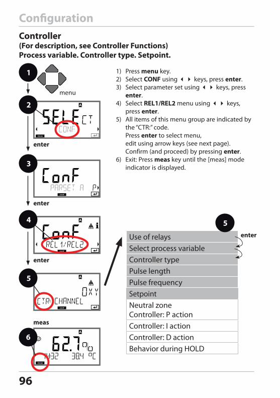
96
ConfigurationController (For description, see Controller Functions)Process variable. Controller type. Setpoint.
1 1) Press menu key.2) Select CONF using keys, press enter.3) Select parameter set using keys, press
enter.4) Select REL1/REL2 menu using keys,
press enter. 5) All items of this menu group are indicated by
the “CTR:” code. Press enter to select menu, edit using arrow keys (see next page). Confirm (and proceed) by pressing enter.
6) Exit: Press meas key until the [meas] mode indicator is displayed.
2
3
4
enter
6
enter
5
enter
meas
Use of relaysSelect process variableController typePulse length Pulse frequencySetpointNeutral zone Controller: P actionController: I actionController: D actionBehavior during HOLD
enter
5
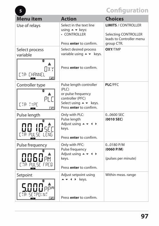
97
ConfigurationMenu item Action ChoicesUse of relays Select in the text line
using keys:• CONTROLLER
Press enter to confirm.
LIMITS / CONTROLLER
Selecting CONTROLLER leads to Controller menu group CTR.
Select process variable
Select desired process variable using keys.
Press enter to confirm.
Controller type Pulse length controller (PLC)or pulse frequency controller (PFC)Select using keys.Press enter to confirm.
Pulse length Only with PLC: Pulse lengthAdjust using keys.
Press enter to confirm.
Pulse frequency Only with PFC: Pulse frequencyAdjust using keys.
Press enter to confirm.
(pulses per minute)
Setpoint Adjust setpoint using keys.
Press enter to confirm.
Within meas. range
5
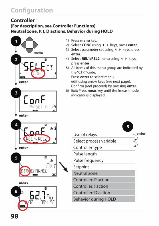
98
Controller (For description, see Controller Functions)Neutral zone. P, I, D actions. Behavior during HOLD
1 1) Press menu key.2) Select CONF using keys, press enter.3) Select parameter set using keys, press
enter.4) Select REL1/REL2 menu using keys,
press enter. 5) All items of this menu group are indicated by
the “CTR:” code. Press enter to select menu, edit using arrow keys (see next page). Confirm (and proceed) by pressing enter.
6) Exit: Press meas key until the [meas] mode indicator is displayed.
2
3
4
enter
6
enter
5
enter
meas
Configuration
Use of relaysSelect process variableController typePulse length Pulse frequencySetpointNeutral zone Controller: P actionController: I actionController: D actionBehavior during HOLD
5
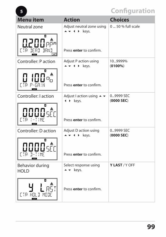
99
ConfigurationMenu item Action ChoicesNeutral zone Adjust neutral zone using
keys.
Press enter to confirm.
0 ... 50 % full scale
Controller: P action Adjust P action using keys.
Press enter to confirm.
Controller: I action Adjust I action using keys.
Press enter to confirm.
Controller: D action Adjust D action using keys.
Press enter to confirm.
Behavior during HOLD
Select response using keys.
Press enter to confirm.
5
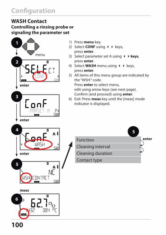
100
ConfigurationWASH ContactControlling a rinsing probe or signaling the parameter set
1) Press menu key.2) Select CONF using keys,
press enter. 3) Select parameter set A using keys,
press enter.4) Select WASH menu using keys,
press enter. 5) All items of this menu group are indicated by
the “WSH:” code. Press enter to select menu, edit using arrow keys (see next page). Confirm (and proceed) using enter.
6) Exit: Press meas key until the [meas] mode indicator is displayed.
FunctionCleaning intervalCleaning durationContact type
enter
5
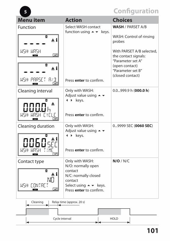
101
ConfigurationMenu item Action ChoicesFunction Select WASH contact
function using keys.
Press enter to confirm.
WASH / PARSET A/B
WASH: Control of rinsing probes
With PARSET A/B selected, the contact signals:“Parameter set A“ (open contact)“Parameter set B“ (closed contact)
Cleaning interval Only with WASH:Adjust value using keys.
Press enter to confirm.
0.0...999.9 h (000.0 h)
Cleaning duration Only with WASH:Adjust value using keys.
Press enter to confirm.
0...9999 SEC (0060 SEC)
Contact type Only with WASH:N/O: normally open contactN/C: normally closed contactSelect using keys.Press enter to confirm.
N/O / N/C
5
Cycle interval
Cleaning Relax time (approx. 20 s)
HOLD
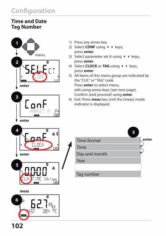
102
ConfigurationTime and DateTag Number
1) Press any arrow key.2) Select CONF using keys,
press enter.3) Select parameter set A using keys,
press enter.4) Select CLOCK or TAG using keys,
press enter. 5) All items of this menu group are indicated by
the “CLK:” or “TAG” code. Press enter to select menu, edit using arrow keys (see next page). Confirm (and proceed) using enter.
6) Exit: Press meas key until the [meas] mode indicator is displayed.
Time formatTimeDay and monthYear
Tag number
enter
5
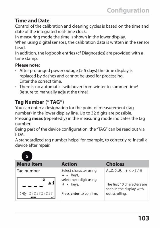
103
Time and DateControl of the calibration and cleaning cycles is based on the time and date of the integrated real-time clock. In measuring mode the time is shown in the lower display. When using digital sensors, the calibration data is written in the sensor head.In addition, the logbook entries (cf Diagnostics) are provided with a time stamp.Please note:• After prolonged power outage (> 5 days) the time display is
replaced by dashes and cannot be used for processing. Enter the correct time.
• There is no automatic switchover from winter to summer time! Be sure to manually adjust the time!
Configuration
Menu item Action ChoicesTag number Select character using
keys,select next digit using keys.
Press enter to confirm.
A...Z, 0...9, – + < > ? / @
The first 10 characters are seen in the display with-out scrolling.
Tag Number (“ TAG“)You can enter a designation for the point of measurement (tag number) in the lower display line. Up to 32 digits are possible.Pressing meas (repeatedly) in the measuring mode indicates the tag number.Being part of the device configuration, the “TAG“ can be read out via IrDA.A standardized tag number helps, for example, to correctly re-install a device after repair.
5
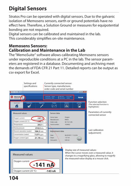
104
Digital SensorsStratos Pro can be operated with digital sensors. Due to the galvanic isolation of Memosens sensors, earth or ground potentials have no effect here. Therefore, a Solution Ground or measures for equipotential bonding are not required. Digital sensors can be calibrated and maintained in the lab. This considerably simplifies on-site maintenance.
Memosens Sensors: Calibration and Maintenance in the LabThe “MemoSuite“ software allows calibrating Memosens sensors under reproducible conditions at a PC in the lab. The sensor param-eters are registered in a database. Documenting and archiving meet the demands of FDA CFR 21 Part 11. Detailed reports can be output as csv export for Excel.
Currently connected sensor: Sensor type, manufacturer, order code and serial number
Settings and specifications
Function selection(The selected function is highlighted.)
Display size of measured values:When the cursor moves over a measured value, it changes to a magnifying glass, allowing to magnify the measured-value display at a mouse click.
Parameters of currently connected sensor
Last calibration (adjustment)
Measured values
Oxygen current
Oxygen current (25 °C)
Temperature
-141 nA
-143 nA
24.5 °C
Sensor data
Sensor type:
Manufacturer:
Order code:
Serial number:
Oxygen
KNICK
SE 715/1-MS
1029852
Adjustment data
Date:
Slope:
06/29/2011 11:22:56
-137 nA
StartCenter Calibration Table View History Statistics pH Buffer
Sensor type:
Manufacturer:
Oxygen
KNICK
Order code:
Serial number:
SE 715/1-MS
1029852
Partial pressure 214.3 hPa
Zero point: 0.00 nA
Percent saturation (water)
Concentration (water)
104.3 %Air
7.571 ppm
Oxygen content (gas) 21.19%Vol
Measured values
Oxygen current
Oxygen current (25 °C)
-141 nA-143 nA
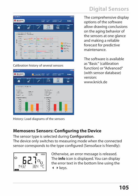
105
The sensor type is selected during Configuration. The device only switches to measuring mode when the connected sensor corresponds to the type configured (Sensoface is friendly):
Digital Sensors
Otherwise, an error message is released. The info icon is displayed. You can display the error text in the bottom line using the keys.
The comprehensive display options of the software allow drawing conclusions on the aging behavior of the sensors at one glance and making a reliable forecast for predictive maintenance.
The software is available as “Basic“ (calibration function) or “Advanced“ (with sensor database) version: www.knick.de
Calibration history of several sensors
History: Load diagrams of the sensors
Memosens Sensors: Configuring the Device
MEMO SENS
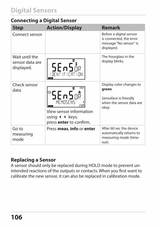
106
Digital SensorsConnecting a Digital SensorStep Action/Display RemarkConnect sensor Before a digital sensor
is connected, the error message “No sensor“ is displayed.
Wait until the sensor data are displayed.
The hourglass in the display blinks.
Check sensor data
MEMO SENS
View sensor information using keys, press enter to confirm.
Display color changes to green.
Sensoface is friendly when the sensor data are okay.
Go to measuring mode
Press meas, info or enter After 60 sec the device automatically returns to measuring mode (time-out).
Replacing a SensorA sensor should only be replaced during HOLD mode to prevent un-intended reactions of the outputs or contacts. When you first want to calibrate the new sensor, it can also be replaced in calibration mode.
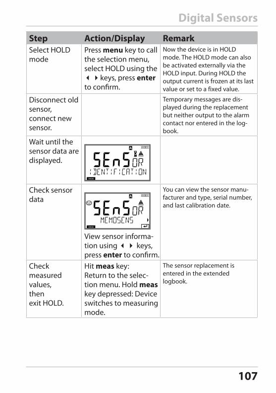
107
Step Action/Display RemarkSelect HOLD mode
Press menu key to call the selection menu, select HOLD using the keys, press enter to confirm.
Now the device is in HOLD mode. The HOLD mode can also be activated externally via the HOLD input. During HOLD the output current is frozen at its last value or set to a fixed value.
Disconnect old sensor,connect new sensor.
Temporary messages are dis-played during the replacement but neither output to the alarm contact nor entered in the log-book.
Wait until the sensor data are displayed.
MEMO SENS
Check sensor data
MEMO SENS
View sensor informa-tion using keys, press enter to confirm.
You can view the sensor manu-facturer and type, serial number, and last calibration date.
Check measured values, then exit HOLD.
Hit meas key: Return to the selec-tion menu. Hold meas key depressed: Device switches to measuring mode.
The sensor replacement is entered in the extended logbook.
Digital Sensors
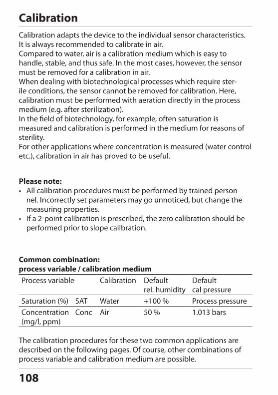
108
CalibrationCalibration adapts the device to the individual sensor characteristics. It is always recommended to calibrate in air. Compared to water, air is a calibration medium which is easy to handle, stable, and thus safe. In the most cases, however, the sensor must be removed for a calibration in air.When dealing with biotechnological processes which require ster-ile conditions, the sensor cannot be removed for calibration. Here, calibration must be performed with aeration directly in the process medium (e.g. after sterilization).In the field of biotechnology, for example, often saturation is measured and calibration is performed in the medium for reasons of sterility. For other applications where concentration is measured (water control etc.), calibration in air has proved to be useful.
Please note:• All calibration procedures must be performed by trained person-
nel. Incorrectly set parameters may go unnoticed, but change the measuring properties.
• If a 2-point calibration is prescribed, the zero calibration should be performed prior to slope calibration.
Common combination: process variable / calibration mediumProcess variable Calibration Default
rel. humidityDefault cal pressure
Saturation (%) SAT Water +100 % Process pressureConcentration (mg/l, ppm)
Conc Air 50 % 1.013 bars
The calibration procedures for these two common applications are described on the following pages. Of course, other combinations of process variable and calibration medium are possible.
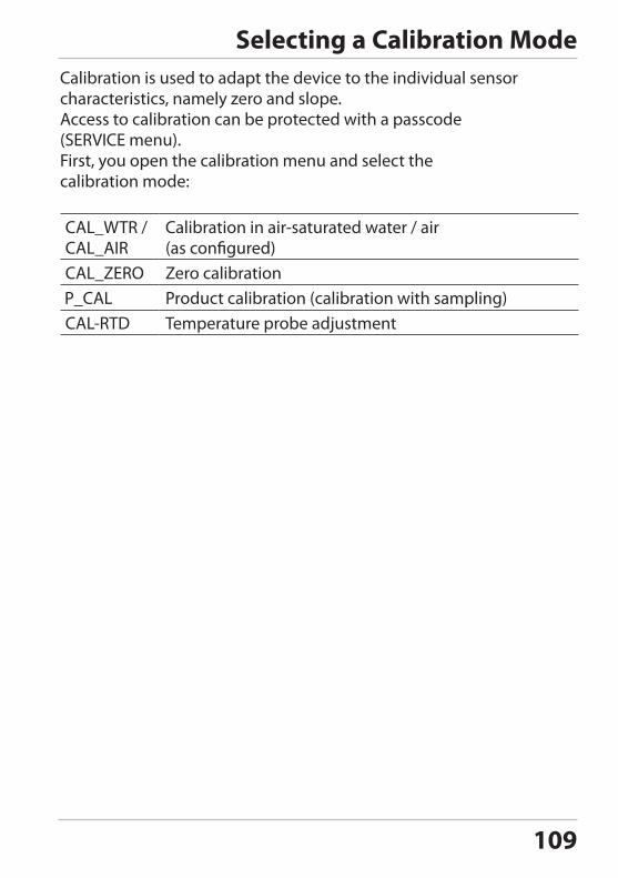
109
Selecting a Calibration ModeCalibration is used to adapt the device to the individual sensor characteristics, namely zero and slope. Access to calibration can be protected with a passcode (SERVICE menu).First, you open the calibration menu and select the calibration mode:
Calibration in air-saturated water / air (as configured)Zero calibrationProduct calibration (calibration with sampling)Temperature probe adjustment
110
Zero CalibrationThe sensor models SE 704, SE 705, SE 706, SE 707 and InPro6000 have very low zero currents. Therefore, a zero calibration is only recom-mended for measurement of oxygen traces. When a zero calibration is performed, the sensor should remain for at least 10 to 30 minutes in the calibration medium in order to obtain stable, non-drifting values. During zero calibration, a drift check is not performed. Zero current of a properly functioning sensor is notably less than 0.5 % of air current. The display (bottom: measured value, top: entered value) does not change until an input current is entered for the zero point. When measuring in an oxygen-free medium, the displayed current can be taken directly.
Zero calibration
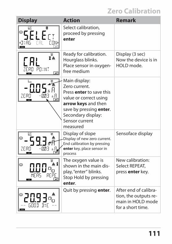
111
Zero CalibrationDisplay Action Remark
Select calibration, proceed by pressing enter
Ready for calibration. Hourglass blinks.Place sensor in oxygen-free medium
Display (3 sec)Now the device is in HOLD mode.
Main display:Zero current. Press enter to save this value or correct using arrow keys and then save by pressing enter.Secondary display: Sensor current measuredDisplay of slopeDisplay of new zero current. End calibration by pressing enter key, place sensor in process
Sensoface display
The oxygen value is shown in the main dis-play, “enter“ blinks. Stop Hold by pressing enter.
New calibration: Select REPEAT,press enter key.
Quit by pressing enter. After end of calibra-tion, the outputs re-main in HOLD mode for a short time.
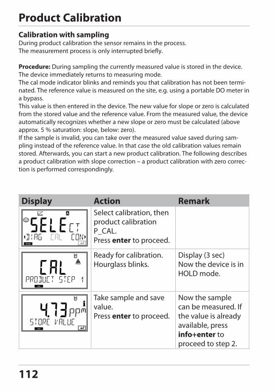
112
Product CalibrationCalibration with samplingDuring product calibration the sensor remains in the process. The measurement process is only interrupted briefly.
Procedure: During sampling the currently measured value is stored in the device. The device immediately returns to measuring mode.The cal mode indicator blinks and reminds you that calibration has not been termi-nated. The reference value is measured on the site, e.g. using a portable DO meter in a bypass.This value is then entered in the device. The new value for slope or zero is calculated from the stored value and the reference value. From the measured value, the device automatically recognizes whether a new slope or zero must be calculated (above approx. 5 % saturation: slope, below: zero).If the sample is invalid, you can take over the measured value saved during sam-pling instead of the reference value. In that case the old calibration values remain stored. Afterwards, you can start a new product calibration. The following describes a product calibration with slope correction – a product calibration with zero correc-tion is performed correspondingly.
Display Action RemarkSelect calibration, then product calibration P_CAL. Press enter to proceed.
Ready for calibration. Hourglass blinks.
Display (3 sec)Now the device is in HOLD mode.
Take sample and save value. Press enter to proceed.
Now the sample can be measured. If the value is already available, press info+enter to proceed to step 2.
Product calibration
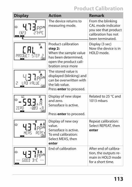
113
Display Action RemarkThe device returns to measuring mode.
From the blinking CAL mode indicator you see that product calibration has not been terminated.
Product calibration step 2:When the sample value has been determined, open the product cali-bration once more
Display (3 sec)Now the device is in HOLD mode.
The stored value is displayed (blinking) and can be overwritten with the lab value.Press enter to proceed.
Display of new slope and zero.Sensoface is active.
Press enter to proceed.
Related to 25 °C and 1013 mbars
Display of new oxy value.Sensoface is active.To end calibration:Select MEAS, then enter
Repeat calibration: Select REPEAT, then enter
End of calibration After end of calibra-tion, the outputs re-main in HOLD mode for a short time.
Product Calibration
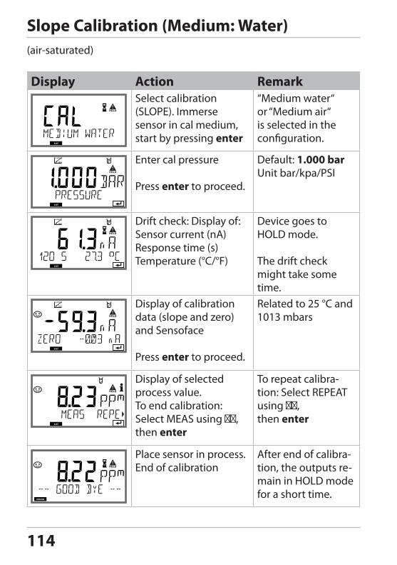
114
Display Action RemarkSelect calibration (SLOPE). Immerse sensor in cal medium, start by pressing enter
“Medium water“ or “Medium air“ is selected in the configuration.
Enter cal pressure
Press enter to proceed.
Default: 1.000 barUnit bar/kpa/PSI
Drift check: Display of:Sensor current (nA)Response time (s)Temperature (°C/°F)
Device goes to HOLD mode.
The drift check might take some time.
Display of calibration data (slope and zero) and Sensoface
Press enter to proceed.
Related to 25 °C and 1013 mbars
Display of selected process value.To end calibration:Select MEAS using , then enter
To repeat calibra-tion: Select REPEAT using , then enter
Place sensor in process.End of calibration
After end of calibra-tion, the outputs re-main in HOLD mode for a short time.
Slope Calibration (Medium: Water)(air-saturated)
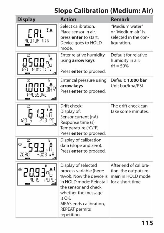
115
Display Action RemarkSelect calibration. Place sensor in air, press enter to start.Device goes to HOLD mode.
“Medium water“ or “Medium air“ is selected in the con-figuration.
Enter relative humidity using arrow keys
Press enter to proceed.
Default for relative humidity in air: rH = 50%
Enter cal pressure using arrow keysPress enter to proceed.
Default: 1.000 barUnit bar/kpa/PSI
Drift check:Display of:Sensor current (nA)Response time (s)Temperature (°C/°F)Press enter to proceed.
The drift check can take some minutes.
Display of calibration data (slope and zero). Press enter to proceed.
Display of selected process variable (here: %vol). Now the device is in HOLD mode: Reinstall the sensor and check whether the message is OK.MEAS ends calibration, REPEAT permits repetition.
After end of calibra-tion, the outputs re-main in HOLD mode for a short time.
Slope Calibration (Medium: Air)
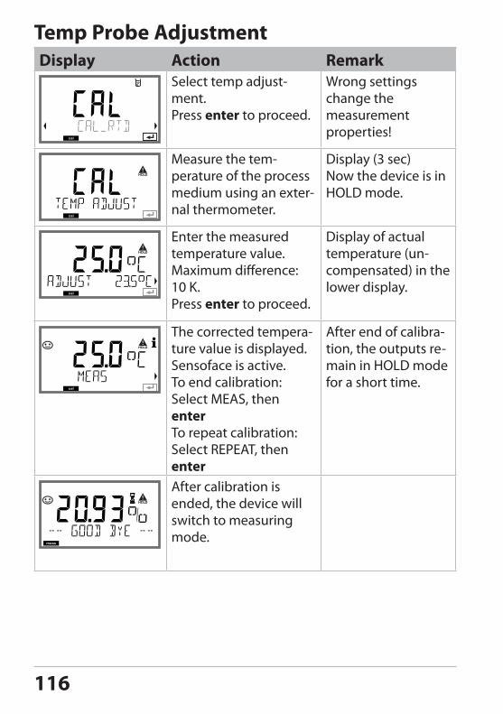
116
Temp Probe AdjustmentDisplay Action Remark
Select temp adjust-ment. Press enter to proceed.
Wrong settings change the measurement properties!
Measure the tem-perature of the process medium using an exter-nal thermometer.
Display (3 sec)Now the device is in HOLD mode.
Enter the measured temperature value.Maximum difference: 10 K.Press enter to proceed.
Display of actual temperature (un-compensated) in the lower display.
The corrected tempera-ture value is displayed.Sensoface is active.To end calibration: Select MEAS, then enterTo repeat calibration: Select REPEAT, then enter
After end of calibra-tion, the outputs re-main in HOLD mode for a short time.
After calibration is ended, the device will switch to measuring mode.
Temp probe adjustment
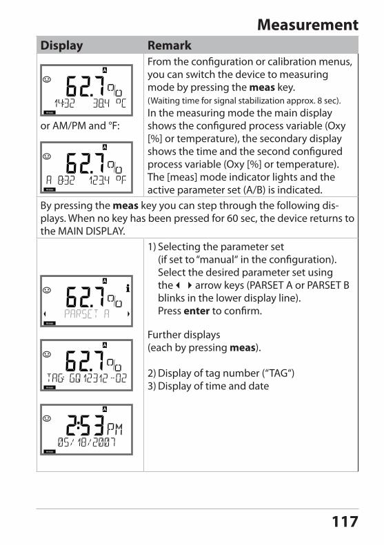
117
MeasurementDisplay Remark
or AM/PM and °F:
From the configuration or calibration menus, you can switch the device to measuring mode by pressing the meas key.(Waiting time for signal stabilization approx. 8 sec). In the measuring mode the main display shows the configured process variable (Oxy [%] or temperature), the secondary display shows the time and the second configured process variable (Oxy [%] or temperature). The [meas] mode indicator lights and the active parameter set (A/B) is indicated.
By pressing the meas key you can step through the following dis-plays. When no key has been pressed for 60 sec, the device returns to the MAIN DISPLAY.
1) Selecting the parameter set (if set to “manual“ in the configuration). Select the desired parameter set using thearrow keys (PARSET A or PARSET B blinks in the lower display line). Press enter to confirm.
Further displays (each by pressing meas).
2) Display of tag number (“TAG“)3) Display of time and date
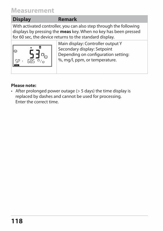
118
MeasurementDisplay RemarkWith activated controller, you can also step through the following displays by pressing the meas key. When no key has been pressed for 60 sec, the device returns to the standard display.
Main display: Controller output YSecondary display: SetpointDepending on configuration setting:%, mg/l, ppm, or temperature.
Please note:• After prolonged power outage (> 5 days) the time display is
replaced by dashes and cannot be used for processing. Enter the correct time.
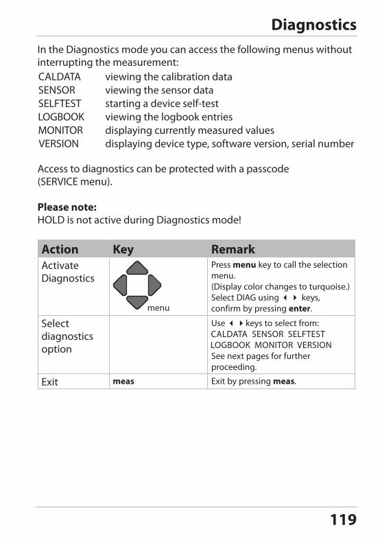
119
DiagnosticsIn the Diagnostics mode you can access the following menus without interrupting the measurement:
viewing the calibration data viewing the sensor data
starting a device self-test viewing the logbook entries displaying currently measured values
displaying device type, software version, serial number
Access to diagnostics can be protected with a passcode (SERVICE menu).
Please note:HOLD is not active during Diagnostics mode!
Action Key RemarkActivate Diagnostics
Press menu key to call the selection menu.(Display color changes to turquoise.)Select DIAG using keys, confirm by pressing enter.
Select diagnostics option
Use keys to select from:
See next pages for further proceeding.
Exit meas Exit by pressing meas.
Diagnostics (DIAG)
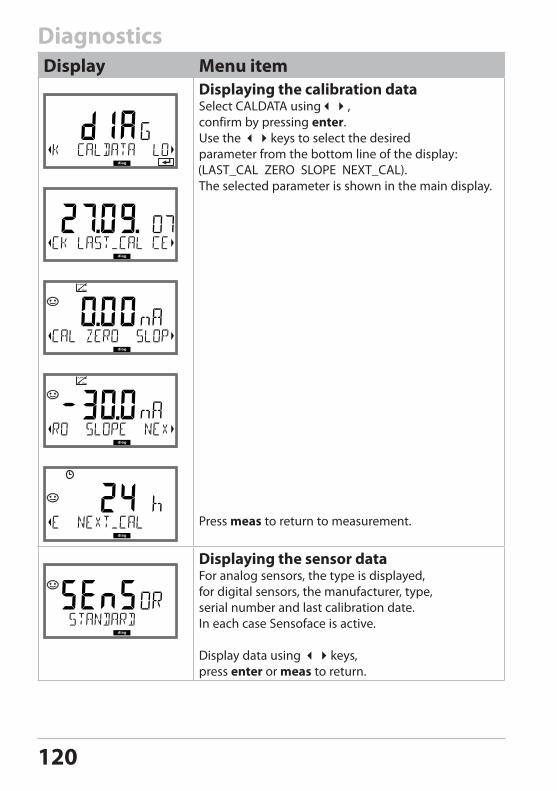
120
DiagnosticsDisplay Menu item
Displaying the calibration dataSelect CALDATA using, confirm by pressing enter.Use the keys to select the desired parameter from the bottom line of the display:
The selected parameter is shown in the main display.
Press meas to return to measurement.
Displaying the sensor dataFor analog sensors, the type is displayed, for digital sensors, the manufacturer, type, serial number and last calibration date.In each case Sensoface is active.
Display data using keys,press enter or meas to return.
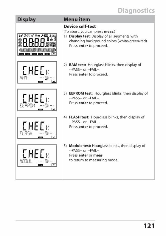
121
DiagnosticsDisplay Menu item
Device self-test(To abort, you can press meas.)1) Display test: Display of all segments with
changing background colors (white/green/red). Press enter to proceed.
2) RAM test: Hourglass blinks, then display of --PASS-- or --FAIL-- Press enter to proceed.
3) EEPROM test: Hourglass blinks, then display of --PASS-- or --FAIL-- Press enter to proceed.
4) FLASH test: Hourglass blinks, then display of --PASS-- or --FAIL-- Press enter to proceed.
5) Module test: Hourglass blinks, then display of --PASS-- or --FAIL-- Press enter or meas to return to measuring mode.
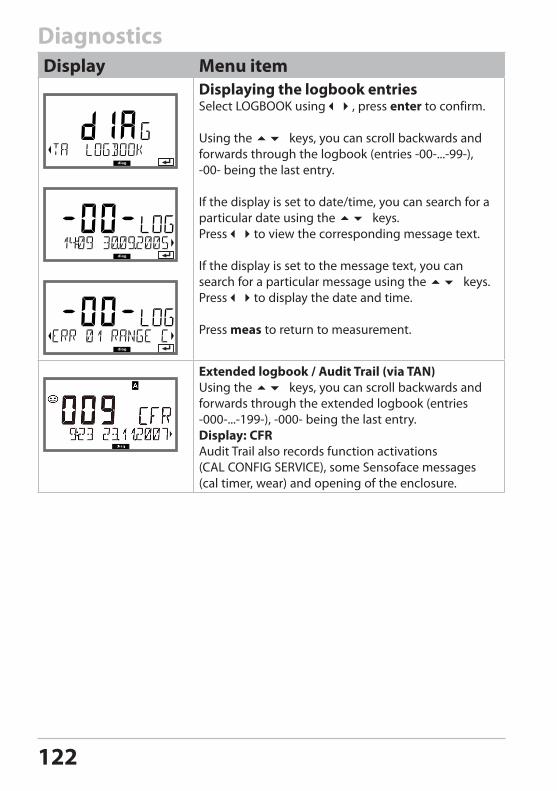
122
DiagnosticsDisplay Menu item
Displaying the logbook entriesSelect LOGBOOK using, press enter to confirm.
Using the keys, you can scroll backwards and forwards through the logbook (entries -00-...-99-), -00- being the last entry.
If the display is set to date/time, you can search for a particular date using the keys.Pressto view the corresponding message text.
If the display is set to the message text, you can search for a particular message using the keys.Pressto display the date and time.
Press meas to return to measurement.
Extended logbook / Audit Trail (via TAN)Using the keys, you can scroll backwards and forwards through the extended logbook (entries -000-...-199-), -000- being the last entry.Display: CFRAudit Trail also records function activations (CAL CONFIG SERVICE), some Sensoface messages (cal timer, wear) and opening of the enclosure.
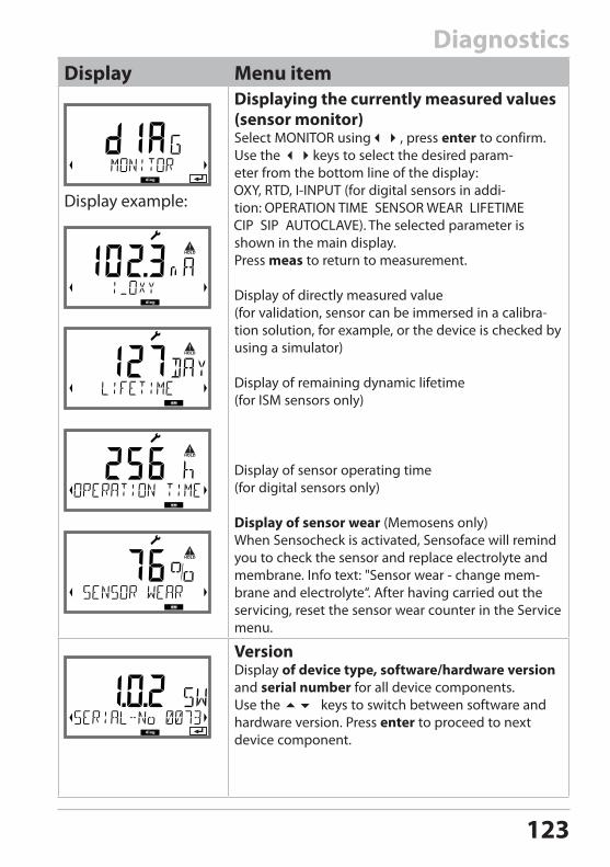
123
DiagnosticsDisplay Menu item
Display example:
Displaying the currently measured values (sensor monitor)Select MONITOR using, press enter to confirm.Use the keys to select the desired param-eter from the bottom line of the display:
(for digital sensors in addi-tion:
The selected parameter is shown in the main display.Press meas to return to measurement.
Display of directly measured value(for validation, sensor can be immersed in a calibra-tion solution, for example, or the device is checked by using a simulator)
Display of remaining dynamic lifetime(for ISM sensors only)
Display of sensor operating time(for digital sensors only)
Display of sensor wear (Memosens only)When Sensocheck is activated, Sensoface will remind you to check the sensor and replace electrolyte and membrane. Info text: "Sensor wear - change mem-brane and electrolyte“. After having carried out the servicing, reset the sensor wear counter in the Service menu.
VersionDisplay of device type, software/hardware version and serial number for all device components. Use the keys to switch between software and hardware version. Press enter to proceed to next device component.
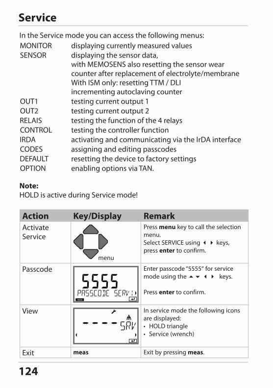
124
ServiceIn the Service mode you can access the following menus:
displaying currently measured valuesdisplaying the sensor data, with MEMOSENS also resetting the sensor wear counter after replacement of electrolyte/membraneWith ISM only: resetting TTM / DLI incrementing autoclaving countertesting current output 1testing current output 2testing the function of the 4 relaystesting the controller functionactivating and communicating via the IrDA interfaceassigning and editing passcodesresetting the device to factory settingsenabling options via TAN.
Note:HOLD is active during Service mode!
Action Key/Display RemarkActivate Service
Press menu key to call the selection menu.Select SERVICE using keys, press enter to confirm.
Passcode Enter passcode “5555“ for service mode using the keys.
Press enter to confirm.
View In service mode the following icons are displayed:• HOLD triangle• Service (wrench)
Exit meas Exit by pressing meas.
Service (SERVICE) A
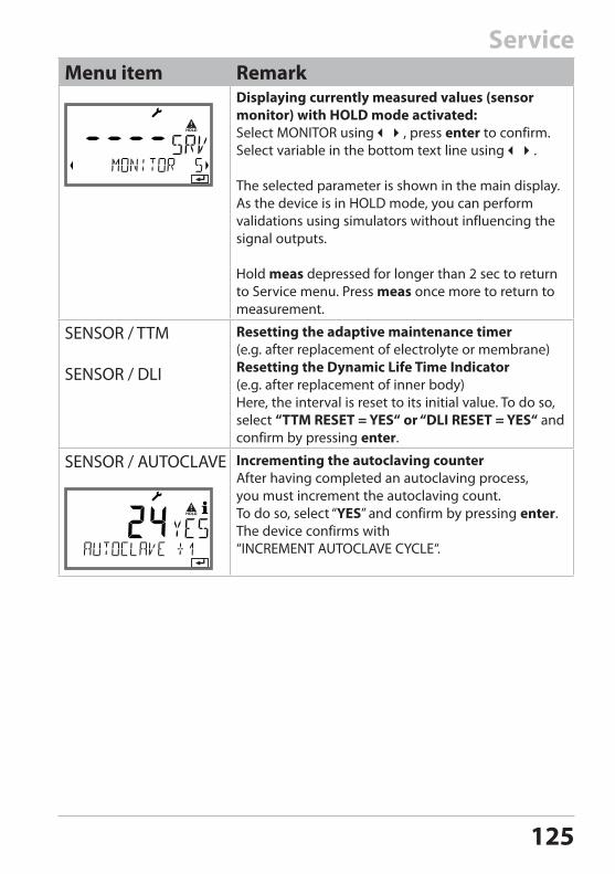
125
ServiceMenu item Remark
Displaying currently measured values (sensor monitor) with HOLD mode activated:Select MONITOR using, press enter to confirm.Select variable in the bottom text line using.
The selected parameter is shown in the main display.As the device is in HOLD mode, you can perform validations using simulators without influencing the signal outputs.
Hold meas depressed for longer than 2 sec to return to Service menu. Press meas once more to return to measurement.
SENSOR / TTM
SENSOR / DLI
Resetting the adaptive maintenance timer (e.g. after replacement of electrolyte or membrane)Resetting the Dynamic Life Time Indicator(e.g. after replacement of inner body) Here, the interval is reset to its initial value. To do so, select “TTM RESET = YES“ or “DLI RESET = YES“ and confirm by pressing enter.
SENSOR / AUTOCLAVE Incrementing the autoclaving counterAfter having completed an autoclaving process, you must increment the autoclaving count.To do so, select “YES” and confirm by pressing enter.The device confirms with “INCREMENT AUTOCLAVE CYCLE“.
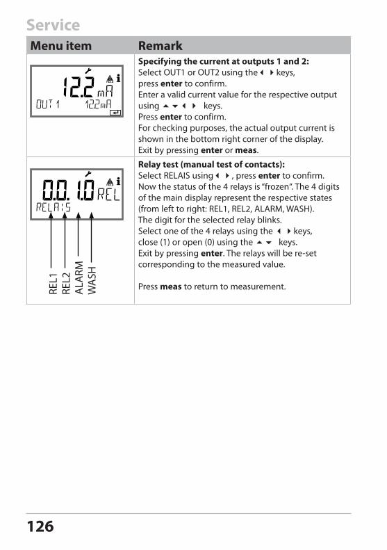
126
ServiceMenu item Remark
Specifying the current at outputs 1 and 2:Select OUT1 or OUT2 using thekeys, press enter to confirm.Enter a valid current value for the respective output using keys.Press enter to confirm.For checking purposes, the actual output current is shown in the bottom right corner of the display.Exit by pressing enter or meas.
Relay test (manual test of contacts):Select RELAIS using, press enter to confirm.Now the status of the 4 relays is “frozen“. The 4 digits of the main display represent the respective states (from left to right: REL1, REL2, ALARM, WASH). The digit for the selected relay blinks. Select one of the 4 relays using the keys, close (1) or open (0) using the keys. Exit by pressing enter. The relays will be re-set corresponding to the measured value.
Press meas to return to measurement.REL1
REL2
ALA
RMW
ASH
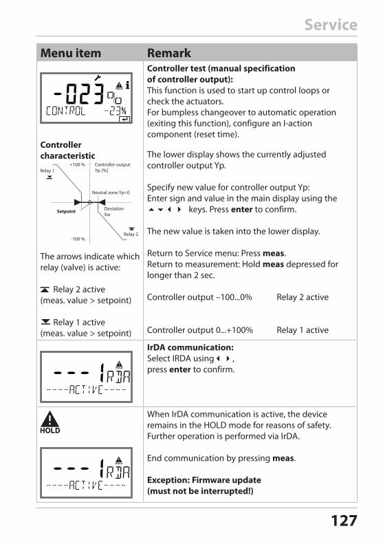
127
Menu item Remark
Controller characteristic
The arrows indicate which relay (valve) is active:
Relay 2 active (meas. value > setpoint)
Relay 1 active (meas. value > setpoint)
Controller test (manual specification of controller output):This function is used to start up control loops or check the actuators.For bumpless changeover to automatic operation (exiting this function), configure an I-action component (reset time).
The lower display shows the currently adjusted controller output Yp.
Specify new value for controller output Yp:Enter sign and value in the main display using the keys. Press enter to confirm.
The new value is taken into the lower display.
Return to Service menu: Press meas.Return to measurement: Hold meas depressed for longer than 2 sec.
Controller output –100...0% Relay 2 active
Controller output 0...+100% Relay 1 active
IrDA communication:Select IRDA using, press enter to confirm.
When IrDA communication is active, the device remains in the HOLD mode for reasons of safety. Further operation is performed via IrDA.
End communication by pressing meas.
Exception: Firmware update (must not be interrupted!)
Setpoint
Controller output Yp [%]
+100 %
-100 %
Deviation Xw
Neutral zone Yp=0
Relay 1
Relay 2
Service
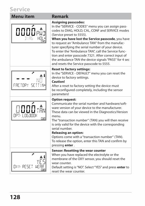
128
ServiceMenu item Remark
Assigning passcodes:In the “SERVICE - CODES“ menu you can assign pass-codes to DIAG, HOLD, CAL, CONF and SERVICE modes (Service preset to 5555).When you have lost the Service passcode, you have to request an “Ambulance TAN“ from the manufac-turer specifying the serial number of your device. To enter the “Ambulance TAN“, call the Service func-tion and enter passcode 7321. After correct input of the ambulance TAN the device signals “PASS“ for 4 sec and resets the Service passcode to 5555.
Reset to factory settings:In the “SERVICE - DEFAULT“ menu you can reset the device to factory settings.Caution!After a reset to factory setting the device must be reconfigured completely, including the sensor parameters!
Option request:Communicate the serial number and hardware/soft-ware version of your device to the manufacturer. These data can be viewed in the Diagnostics/Version menu.The “transaction number“ (TAN) you will then receive is only valid for the device with the corresponding serial number.Releasing an option:Options come with a “transaction number“ (TAN). To release the option, enter this TAN and confirm by pressing enter .
Sensor: Resetting the wear counterWhen you have replaced the electrolyte or the membrane of the OXY sensor, you should reset the wear counter.Default setting is “NO”. Select “YES” and press enter to reset the wear counter.
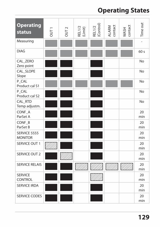
129
Operating status
OU
T 1
OU
T 2
REL1
/2
(Lim
it)
REL1
/2
(Con
trol
)
ALA
RM
cont
act
WA
SH
cont
act
Tim
e ou
t
Measuring -
DIAG 60 s
CAL_ZEROZero point
No
CAL_SLOPE Slope
No
P_CAL Product cal S1
No
P_CAL Product cal S2
No
CAL_RTD Temp adjustm.
No
CONF_A ParSet A
20 min
CONF_B ParSet B
20 min
SERVICE 5555 MONITOR
20 min
SERVICE OUT 1 20 min
SERVICE OUT 2 20 min
SERVICE RELAIS 20 min
SERVICE CONTROL
20 min
SERVICE IRDA 20 min
SERVICE CODES 20 min
Operating StatesOperating states A
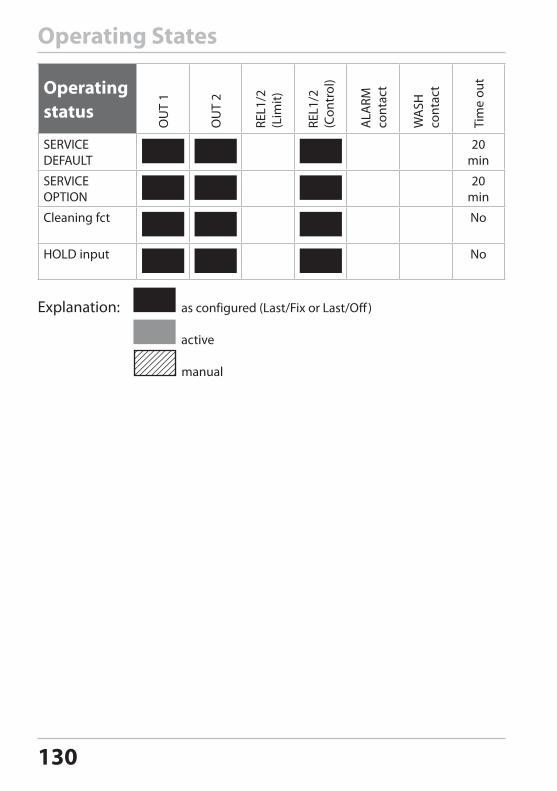
130
Operating status
OU
T 1
OU
T 2
REL1
/2
(Lim
it)
REL1
/2
(Con
trol
)
ALA
RM
cont
act
WA
SH
cont
act
Tim
e ou
t
SERVICE DEFAULT
20 min
SERVICE OPTION
20 min
Cleaning fct No
HOLD input No
Explanation: as configured (Last/Fix or Last/Off )
active
manual
Operating States
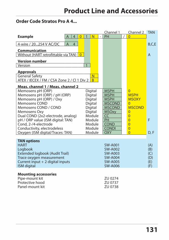
131
Product Line and AccessoriesOrder Code Stratos Pro A 4...
Channel 1 Channel 2 TANExample A 4 0 1 N - PH / 0
4-wire / 20...254 V AC/DC A 4 B,C,E
CommunicationWithout (HART retrofittable via TAN) 0 A
Version numberVersion 1
ApprovalsGeneral Safety NATEX / IECEX / FM / CSA Zone 2 / Cl 1 Div 2 B
Meas. channel 1 / Meas. channel 2Memosens pH (ORP) Digital MSPH 0Memosens pH (ORP) / pH (ORP) Digital MSPH MSPHMemosens pH (ORP) / Oxy Digital MSPH MSOXYMemosens COND Digital MSCOND 0Memosens COND / COND Digital MSCOND MSCONDMemosens Oxy Digital MSOxy 0Dual COND (2x2-electrode, analog) Module CC 0pH / ORP value (ISM digital: TAN) Module PH 0 FCond, 2-/4-electrode Module COND 0Conductivity, electrodeless Module CONDI 0Oxygen (ISM digital/Traces: TAN) Module OXY 0 D, F
TAN optionsHART SW-A001 (A)Logbook SW-A002 (B)Extended logbook (Audit Trail) SW-A003 (C)Trace oxygen measurement SW-A004 (D)Current input + 2 digital inputs SW-A005 (E)ISM digital SW-A006 (F)
Mounting accessoriesPipe-mount kit ZU 0274Protective hood ZU 0737Panel-mount kit ZU 0738
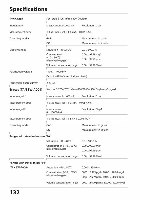
132
SpecificationsStandard Sensors: SE 706, InPro 6800, Oxyferm
Input range Meas. current 0 ... 600 nA Resolution 10 pA
Measurement error < 0.5% meas. val. + 0.05 nA + 0.005 nA/K
Operating modes GAS Measurement in gases
DO Measurement in liquids
Display ranges Saturation (–10 ... 80°C) 0.0 ... 600.0 %
Concentration (–10 ... 80°C)(dissolved oxygen)
0.00 ... 99.99 mg/l
0.00 ... 99.99 ppm
Volume concentration in gas 0.00 ... 99.99 %vol
Polarization voltage –400 ... –1000 mV
Default –675 mV (resolution < 5 mV)
Permissible guard current ≤ 20 µA
Traces (TAN SW-A004) Sensors: SE 706/707; InPro 6800/6900/6950; Oxyferm/Oxygold
Input range I 1) Meas. current 0 ... 600 nA Resolution 10 pA
Measurement error < 0.5% meas. val. + 0.05 nA + 0.005 nA/K
Input range II 1) Meas. current 0 ... 100000 nA
Resolution 166 pA
Measurement error < 0.5% meas. val. + 0.8 nA + 0.008 nA/K
Operating modes GAS Measurement in gases
DO Measurement in liquids
Ranges with standard sensors “10“
Saturation (–10 ... 80°C) 0.0 ... 600.0 %
Concentration (–10 ... 80°C)(dissolved oxygen)
0.00 ... 99.99 mg/l
0.00 ... 99.99 ppm
Volume concentration in gas 0.00 ... 99.99 %vol
Ranges with trace sensors “01“
(TAN SW-A004) Saturation (–10 ... 80°C) 0.000 ... 150.0 %
Concentration (–10 ... 80°C)(dissolved oxygen)
0000 ... 9999 µg/l / 10.00 ... 20.00 mg/l
0000 ... 9999 ppb / 10.00 ... 20.00 ppm
Volume concentration in gas 0000 ... 9999 ppm / 1.000 ... 50.00 %vol
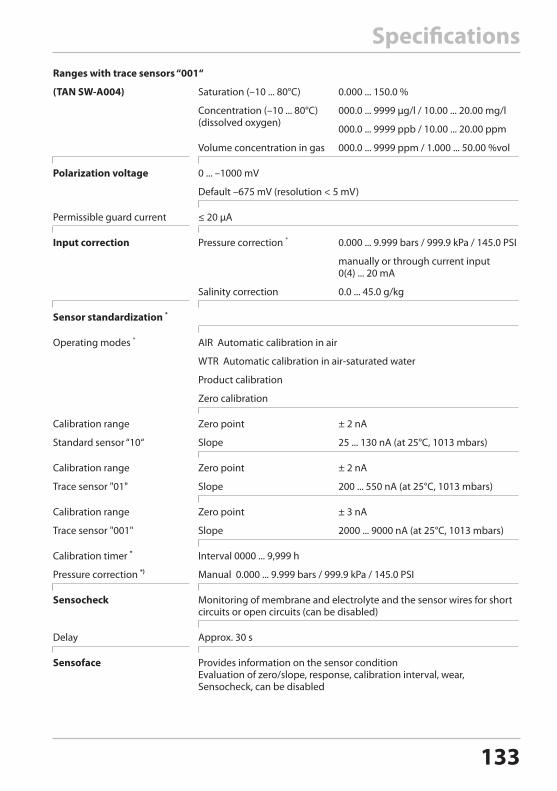
133
SpecificationsRanges with trace sensors “001“
(TAN SW-A004) Saturation (–10 ... 80°C) 0.000 ... 150.0 %
Concentration (–10 ... 80°C)(dissolved oxygen)
000.0 ... 9999 µg/l / 10.00 ... 20.00 mg/l
000.0 ... 9999 ppb / 10.00 ... 20.00 ppm
Volume concentration in gas 000.0 ... 9999 ppm / 1.000 ... 50.00 %vol
Polarization voltage 0 ... –1000 mV
Default –675 mV (resolution < 5 mV)
Permissible guard current ≤ 20 µA
Input correction Pressure correction * 0.000 ... 9.999 bars / 999.9 kPa / 145.0 PSI
manually or through current input 0(4) ... 20 mA
Salinity correction 0.0 ... 45.0 g/kg
Sensor standardization *
Operating modes * AIR Automatic calibration in air
WTR Automatic calibration in air-saturated water
Product calibration
Zero calibration
Calibration range Zero point ± 2 nA
Standard sensor “10“ Slope 25 ... 130 nA (at 25°C, 1013 mbars)
Calibration range Zero point ± 2 nA
Trace sensor "01" Slope 200 ... 550 nA (at 25°C, 1013 mbars)
Calibration range Zero point ± 3 nA
Trace sensor "001" Slope 2000 ... 9000 nA (at 25°C, 1013 mbars)
Calibration timer * Interval 0000 ... 9,999 h
Pressure correction *) Manual 0.000 ... 9.999 bars / 999.9 kPa / 145.0 PSI
Sensocheck Monitoring of membrane and electrolyte and the sensor wires for short circuits or open circuits (can be disabled)
Delay Approx. 30 s
Sensoface Provides information on the sensor conditionEvaluation of zero/slope, response, calibration interval, wear, Sensocheck, can be disabled
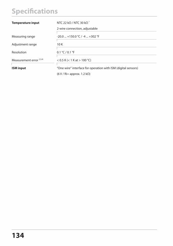
134
SpecificationsTemperature input NTC 22 kΩ / NTC 30 kΩ *
2-wire connection, adjustable
Measuring range -20.0 ... +150.0 °C / -4 ... +302 °F
Adjustment range 10 K
Resolution 0.1 °C / 0.1 °F
Measurement error 2,3,4) < 0.5 K (< 1 K at > 100 °C)
ISM input “One wire“ interface for operation with ISM (digital sensors)
(6 V / Ri= approx. 1.2 kΩ)
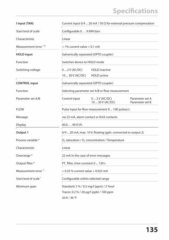
135
SpecificationsI input (TAN) Current input 0/4 ... 20 mA / 50 Ω for external pressure compensation
Start/end of scale Configurable 0 … 9.999 bars
Characteristic Linear
Measurement error 1.3) < 1% current value + 0.1 mA
HOLD input Galvanically separated (OPTO coupler)
Function Switches device to HOLD mode
Switching voltage 0 ... 2 V (AC/DC) HOLD inactive
10 ... 30 V (AC/DC) HOLD active
CONTROL input Galvanically separated (OPTO coupler)
Function Selecting parameter set A/B or flow measurement
Parameter set A/B Control input
0 ... 2 V (AC/DC) 10 ... 30 V (AC/DC)
Parameter set A Parameter set B
FLOW Pulse input for flow measurement 0 ... 100 pulses/s
Message via 22 mA, alarm contact or limit contacts
Display 00.0 … 99.9 l/h
Output 1 0/4 ... 20 mA, max. 10 V, floating (galv. connected to output 2)
Process variable * O2 saturation / O2 concentration / Temperature
Characteristic Linear
Overrange * 22 mA in the case of error messages
Output filter * PT1 filter, time constant 0 ... 120 s
Measurement error 1) < 0.25 % current value + 0.025 mA
Start/end of scale * Configurable within selected range
Minimum span Standard: 5 % / 0.5 mg/l (ppm) / 2 %vol
Traces: 0.2 % / 20 μg/l (ppb) / 100 ppm
20 K / 36 °F
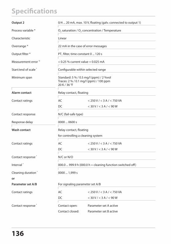
136
SpecificationsOutput 2 0/4 ... 20 mA, max. 10 V, floating (galv. connected to output 1)
Process variable * O2 saturation / O2 concentration / Temperature
Characteristic Linear
Overrange * 22 mA in the case of error messages
Output filter * PT1 filter, time constant 0 ... 120 s
Measurement error 1) < 0.25 % current value + 0.025 mA
Start/end of scale * Configurable within selected range
Minimum span Standard: 5 % / 0.5 mg/l (ppm) / 2 %vol Traces: 2 % / 0.1 mg/l (ppm) / 100 ppm 20 K / 36 °F
Alarm contact Relay contact, floating
Contact ratings AC < 250 V / < 3 A / < 750 VA
DC < 30 V / < 3 A / < 90 W
Contact response N/C (fail-safe type)
Response delay 0000 ... 0600 s
Wash contact Relay contact, floating
for controlling a cleaning system
Contact ratings AC < 250 V / < 3 A / < 750 VA
DC < 30 V / < 3 A / < 90 W
Contact response * N/C or N/O
Interval * 000.0 ... 999.9 h (000.0 h = cleaning function switched off)
Cleaning duration * 0000 ... 1,999 s
or
Parameter set A/B For signaling parameter set A/B
Contact ratings AC < 250 V / < 3 A / < 750 VA
DC < 30 V / < 3 A / < 90 W
Contact response * Contact open: Parameter set A active
Contact closed: Parameter set B active
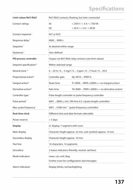
137
SpecificationsLimit values Rel1/Rel2 Rel1/Rel2 contacts, floating, but inter-connected
Contact ratings AC < 250 V / < 3 A / < 750 VA
DC < 30 V / < 3 A / < 90 W
Contact response * N/C or N/O
Response delay * 0000 ... 9999 s
Setpoints * As desired within range
Hysteresis * User-defined
PID process controller Output via Rel1/Rel2 relay contacts (see limit values)
Setpoint specification* Within selected range
Neutral zone * 0 ... 50 % / 0 ... 5 mg/l / 0 ... 5 ppm / 0 ... 5 %vol / 0 ... 50 K
Proportional action* Controller gain Kp: 0010 ... 9999 %
Integral action* Reset time Tr: 0000 ... 9999 s (0000 s = no integral action)
Derivative action* Rate time Td: 0000 ... 9999 s (0000 s = no derivative action)
Controller type * Pulse length controller or pulse frequency controller
Pulse period * 0001 ... 0600 s, min. ON time 0.5 s (pulse length controller)
Max. pulse frequency* 0001 ... 0180 min–1 (pulse frequency controller)
Real-time clock Different time and date formats selectable
Power reserve > 5 days
Display LC display, 7-segment with icons
Main display Character height approx. 22 mm, unit symbols approx. 14 mm
Secondary display Character height approx. 10 mm
Text line 14 characters, 14 segments
Sensoface 3 status indicators (friendly, neutral, sad face)
Mode Indicators meas, cal, conf, diag
Further icons for configuration and messages
Alarm indication Display blinks, red backlighting
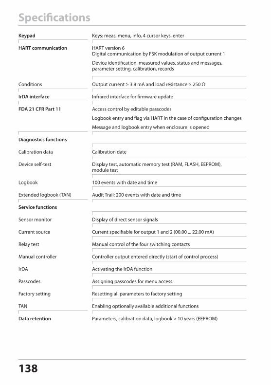
138
SpecificationsKeypad Keys: meas, menu, info, 4 cursor keys, enter
HART communication HART version 6 Digital communication by FSK modulation of output current 1
Device identification, measured values, status and messages, parameter setting, calibration, records
Conditions Output current ≥ 3.8 mA and load resistance ≥ 250 Ω
IrDA interface Infrared interface for firmware update
FDA 21 CFR Part 11 Access control by editable passcodes
Logbook entry and flag via HART in the case of configuration changes
Message and logbook entry when enclosure is opened
Diagnostics functions
Calibration data Calibration date
Device self-test Display test, automatic memory test (RAM, FLASH, EEPROM), module test
Logbook 100 events with date and time
Extended logbook (TAN) Audit Trail: 200 events with date and time
Service functions
Sensor monitor Display of direct sensor signals
Current source Current specifiable for output 1 and 2 (00.00 ... 22.00 mA)
Relay test Manual control of the four switching contacts
Manual controller Controller output entered directly (start of control process)
IrDA Activating the IrDA function
Passcodes Assigning passcodes for menu access
Factory setting Resetting all parameters to factory setting
TAN Enabling optionally available additional functions
Data retention Parameters, calibration data, logbook > 10 years (EEPROM)
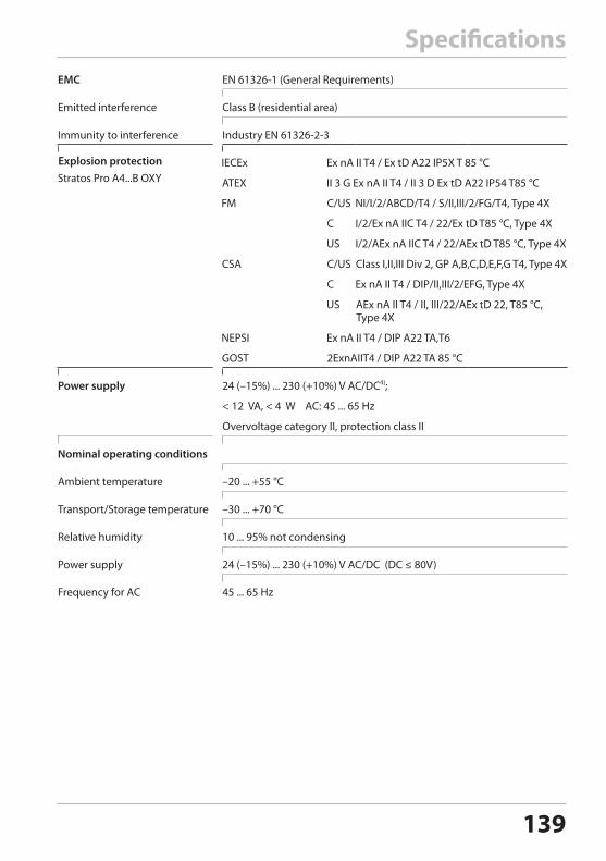
139
SpecificationsEMC EN 61326-1 (General Requirements)
Emitted interference Class B (residential area)
Immunity to interference Industry EN 61326-2-3
Explosion protection
Power supply 24 (–15%) ... 230 (+10%) V AC/DC4);
< 12 VA, < 4 W AC: 45 ... 65 Hz
Overvoltage category II, protection class II
Nominal operating conditions
Ambient temperature –20 ... +55 °C
Transport/Storage temperature –30 ... +70 °C
Relative humidity 10 ... 95% not condensing
Power supply 24 (–15%) ... 230 (+10%) V AC/DC (DC ≤ 80V)
Frequency for AC 45 ... 65 Hz
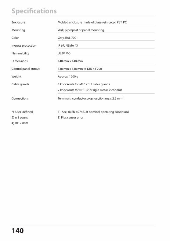
140
Enclosure Molded enclosure made of glass-reinforced PBT, PC
Mounting Wall, pipe/post or panel mounting
Color Gray, RAL 7001
Ingress protection IP 67, NEMA 4X
Flammability UL 94 V-0
Dimensions 148 mm x 148 mm
Control panel cutout 138 mm x 138 mm to DIN 43 700
Weight Approx. 1200 g
Cable glands 3 knockouts for M20 x 1.5 cable glands
2 knockouts for NPT ½” or rigid metallic conduit
Connections Terminals, conductor cross-section max. 2.5 mm2
*) User-defined 1) Acc. to EN 60746, at nominal operating conditions
2) ± 1 count 3) Plus sensor error
4) DC ≤ 80 V
Specifications
141
Error HandlingAlarm condition:• The display backlighting turns red• The alarm icon is displayed• The complete measured-value display blinks• “ERR xxx“ is displayed in the lower menu linePress the [info] key to view a short error text:• The error text appears in the lower menu line• The main display reads “InFo“.
Parameter errors:Configuration data such as current range, limit values, etc are checked during the input.If they are out of range,• “ERR xxx“ is displayed for 3 sec,• the display backlighting flashes red,• the respective maximum or minimum value is shown,• input must be repeated.
If a faulty parameter arrives through the interface (IrDA, HART),• an error message will be displayed: “ERR 100...199“• the faulty parameter can be localized by pressing the [info] key
Calibration errors:If errors occur during calibration,• an error message will be displayed
Sensoface:If the Sensoface becomes sad,• the display backlighting will turn purple• the cause can be seen by pressing the info key• the calibration data can be seen in the Diagnostics menu
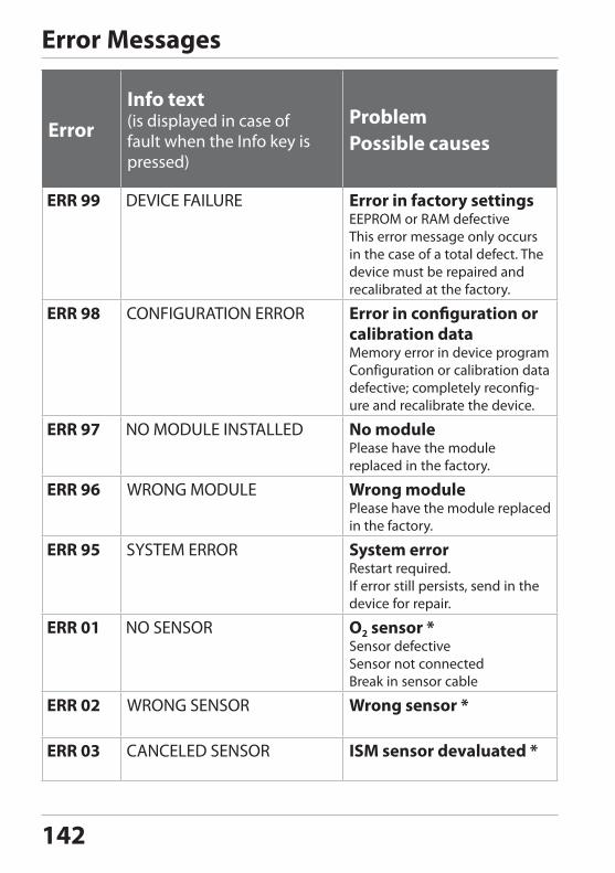
142
Error Messages
ErrorInfo text(is displayed in case of fault when the Info key is pressed)
Problem Possible causes
Error in factory settingsEEPROM or RAM defectiveThis error message only occurs in the case of a total defect. The device must be repaired and recalibrated at the factory.
Error in configuration or calibration dataMemory error in device programConfiguration or calibration data defective; completely reconfig-ure and recalibrate the device.
No modulePlease have the module replaced in the factory.
Wrong modulePlease have the module replaced in the factory.
System errorRestart required. If error still persists, send in the device for repair.
O2 sensor *Sensor defectiveSensor not connectedBreak in sensor cable
Wrong sensor *
ISM sensor devaluated *
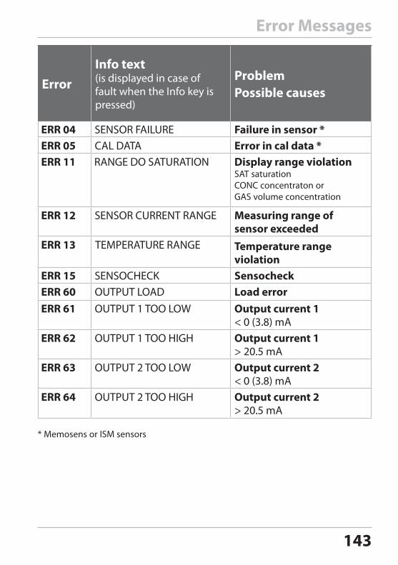
143
Error Messages
ErrorInfo text(is displayed in case of fault when the Info key is pressed)
Problem Possible causes
Failure in sensor * Error in cal data * Display range violation
SAT saturationCONC concentraton orGAS volume concentration
Measuring range of sensor exceeded
Temperature range violation
Sensocheck Load error
Output current 1 < 0 (3.8) mA
Output current 1 > 20.5 mA
Output current 2 < 0 (3.8) mA
Output current 2 > 20.5 mA
* Memosens or ISM sensors
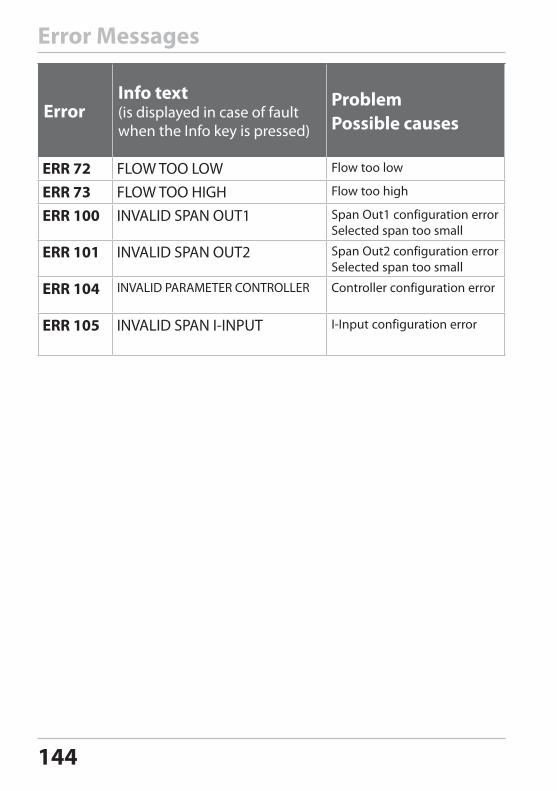
144
Error Messages
ErrorInfo text(is displayed in case of fault when the Info key is pressed)
Problem Possible causes
Flow too low
Flow too high
Span Out1 configuration error Selected span too small
Span Out2 configuration errorSelected span too small
Controller configuration error
I-Input configuration error
145
Sensoface(Sensocheck must have been activated during configuration.)
The smiley in the display (Sensoface) alerts to sensor problems (defective sensor, sensor wear, defective cable, maintenance request). The permitted calibration ranges and the conditions for a friendly, neutral, or sad Sensoface are summarized in the following table. Additional icons refer to the error cause.
SensocheckContinuously monitors the sensor and its wiring. Critical values make the Sensoface “sad” and the corresponding icon blinks:
The Sensocheck message is also output as error message Err 15. The alarm contact (A4... only) is active, the display backlighting turns red, output current 1 is set to 22 mA (when configured correspondingly). Sensocheck can be switched off during configuration (then Sensoface is also disabled). Exception: After a calibration a smiley is always displayed for confirmation.
Please note:The worsening of a Sensoface criterion leads to the devaluation of the Sensoface indicator (Smiley becomes “sad”). An improvement of the Sensoface indicator can only take place after calibration or removal of the sensor defect.
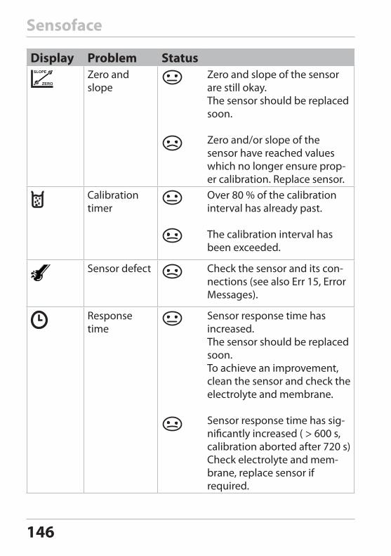
146
Sensoface
Display Problem StatusZero and slope
Zero and slope of the sensor are still okay.The sensor should be replaced soon.
Zero and/or slope of the sensor have reached values which no longer ensure prop-er calibration. Replace sensor.
Calibration timer
Over 80 % of the calibration interval has already past.
The calibration interval has been exceeded.
Sensor defect Check the sensor and its con-nections (see also Err 15, Error Messages).
Response time
Sensor response time has increased.The sensor should be replaced soon.To achieve an improvement, clean the sensor and check the electrolyte and membrane.
Sensor response time has sig-nificantly increased ( > 600 s, calibration aborted after 720 s)Check electrolyte and mem-brane, replace sensor if required.
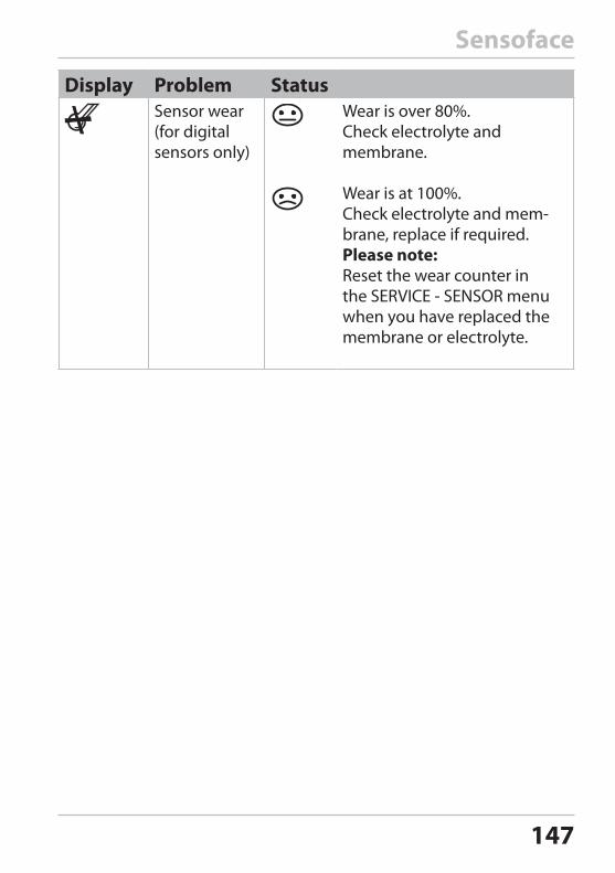
147
Sensoface
Display Problem StatusSensor wear (for digital sensors only)
Wear is over 80%. Check electrolyte and membrane.
Wear is at 100%.Check electrolyte and mem-brane, replace if required.Please note: Reset the wear counter in the SERVICE - SENSOR menu when you have replaced the membrane or electrolyte.
148
FDA 21 CFR Part 11Conformity with FDA 21 CFR Part 11In their directive “Title 21 Code of Federal Regulations, 21 CFR Part 11, Electronic Records; Electronic Signatures“ the US American health agency FDA (Food and Drug Administration) regulates the production and processing of electronic documents for pharmaceutical devel-opment and production. This results in requirements for measuring devices used for corresponding applications. The following features ensure that the measuring devices of this Series meet the demands of FDA 21 CFR Part 11:
Electronic Signature – PasscodesAccess to the device functions is regulated and limited by individually adjustable codes – “Passcodes“ (see SERVICE). This prevents unauthor-ized modification of device settings or manipulation of the measure-ment results. Appropriate use of these passcodes makes them suitable as electronic signature.
Audit TrailEvery (manual) change of device settings can be automatically docu-mented. Each change is tagged with a “Configuration Change Flag“, which can be interrogated and documented using HART communica-tion. Altered device settings or parameters can also be retrieved and documented using HART communication.
Extended logbookAudit Trail also records function activations (CAL, CONFIG, SERVICE), some Sensoface messages (cal timer, wear), and opening of the enclosure.
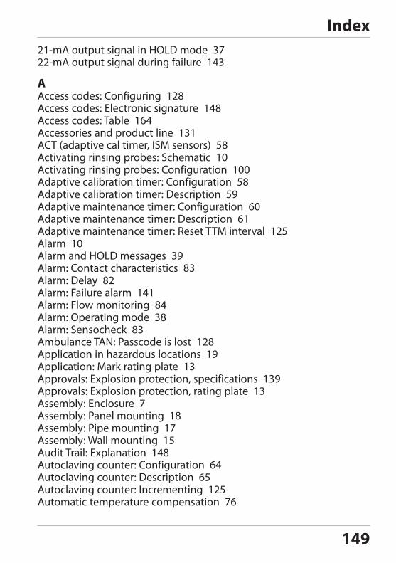
149
21-mA output signal in HOLD mode 3722-mA output signal during failure 143
AAccess codes: Configuring 128Access codes: Electronic signature 148Access codes: Table 164Accessories and product line 131ACT (adaptive cal timer, ISM sensors) 58Activating rinsing probes: Schematic 10Activating rinsing probes: Configuration 100Adaptive calibration timer: Configuration 58Adaptive calibration timer: Description 59Adaptive maintenance timer: Configuration 60Adaptive maintenance timer: Description 61Adaptive maintenance timer: Reset TTM interval 125Alarm 10Alarm and HOLD messages 39Alarm: Contact characteristics 83Alarm: Delay 82Alarm: Failure alarm 141Alarm: Flow monitoring 84Alarm: Operating mode 38Alarm: Sensocheck 83Ambulance TAN: Passcode is lost 128Application in hazardous locations 19Application: Mark rating plate 13Approvals: Explosion protection, specifications 139Approvals: Explosion protection, rating plate 13Assembly: Enclosure 7Assembly: Panel mounting 18Assembly: Pipe mounting 17Assembly: Wall mounting 15Audit Trail: Explanation 148Autoclaving counter: Configuration 64Autoclaving counter: Description 65Autoclaving counter: Incrementing 125Automatic temperature compensation 76
Index
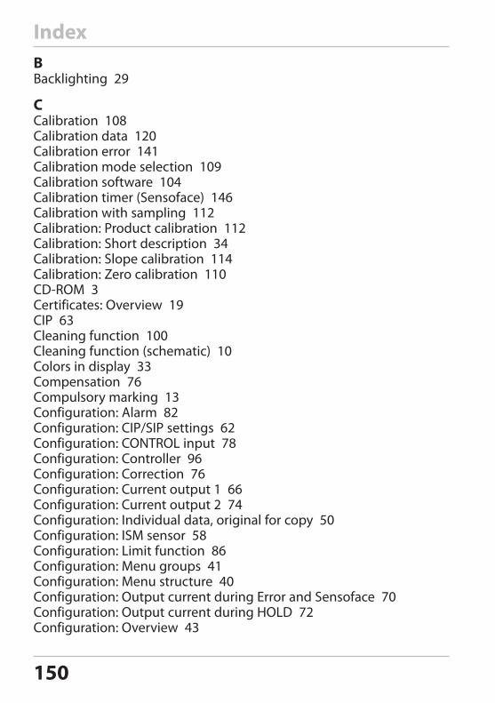
150
BBacklighting 29
CCalibration 108Calibration data 120Calibration error 141Calibration mode selection 109Calibration software 104Calibration timer (Sensoface) 146Calibration with sampling 112Calibration: Product calibration 112Calibration: Short description 34Calibration: Slope calibration 114Calibration: Zero calibration 110CD-ROM 3Certificates: Overview 19CIP 63Cleaning function 100Cleaning function (schematic) 10Colors in display 33Compensation 76Compulsory marking 13Configuration: Alarm 82Configuration: CIP/SIP settings 62Configuration: CONTROL input 78Configuration: Controller 96Configuration: Correction 76Configuration: Current output 1 66Configuration: Current output 2 74Configuration: Individual data, original for copy 50Configuration: ISM sensor 58Configuration: Limit function 86Configuration: Menu groups 41Configuration: Menu structure 40Configuration: Output current during Error and Sensoface 70Configuration: Output current during HOLD 72Configuration: Overview 43
Index
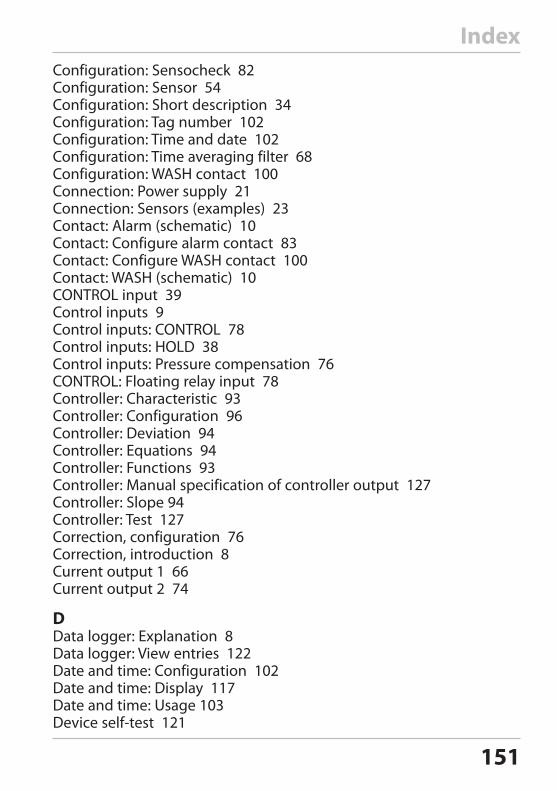
151
IndexConfiguration: Sensocheck 82Configuration: Sensor 54Configuration: Short description 34Configuration: Tag number 102Configuration: Time and date 102Configuration: Time averaging filter 68Configuration: WASH contact 100Connection: Power supply 21Connection: Sensors (examples) 23Contact: Alarm (schematic) 10Contact: Configure alarm contact 83Contact: Configure WASH contact 100Contact: WASH (schematic) 10CONTROL input 39Control inputs 9Control inputs: CONTROL 78Control inputs: HOLD 38Control inputs: Pressure compensation 76CONTROL: Floating relay input 78Controller: Characteristic 93Controller: Configuration 96Controller: Deviation 94Controller: Equations 94Controller: Functions 93Controller: Manual specification of controller output 127Controller: Slope 94Controller: Test 127Correction, configuration 76Correction, introduction 8Current output 1 66Current output 2 74
DData logger: Explanation 8Data logger: View entries 122Date and time: Configuration 102Date and time: Display 117Date and time: Usage 103Device self-test 121
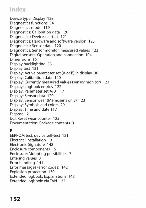
152
IndexDevice type: Display 123Diagnostics functions 34Diagnostics mode 119Diagnostics: Calibration data 120Diagnostics: Device self-test 121Diagnostics: Hardware and software version 123Diagnostics: Sensor data 120Diagnostics: Sensor monitor, measured values 123Digital sensors: Operation and connection 104Dimensions 16Display backlighting 33Display test 121Display: Active parameter set (A or B) in display 30Display: Calibration data 120Display: Currently measured values (sensor monitor) 123Display: Logbook entries 122Display: Parameter set A/B 117Display: Sensor data 120Display: Sensor wear (Memosens only) 123Display: Symbols and colors 29Display: Time and date 117Disposal 2DLI: Reset wear counter 125Documentation: Package contents 3
EEEPROM test, device self-test 121Electrical installation 13Electronic Signature 148Enclosure components 15Enclosure: Mounting possibilities 7Entering values 31Error handling 141Error messages (error codes) 142Explosion protection 139Extended logbook: Explanations 148Extended logbook: Via TAN 122
153
FFACE message, Sensoface, 22-mA output current 71Factory settings 128FAIL message, 22-mA output current 71Fault current 72FDA 21 CFR Part 11: Requirements 148FIX: Output signal in HOLD mode 37FLASH test 121FLOW 81Flow measurement 80Flow monitoring 84
HHOLD mode 37HOLD: Configure output signal 73HOLD: Controller behavior 98HOLD: Exit 37HOLD: External activation 38HOLD: Manual activation 38HOLD: Operating mode 37HOLD: Output signal response 37HOLD: Response of output signal 37HOLD: Short description 34Hysteresis: Application 89
IIncorrect use 12Inductive load 26Info text 142Installation: Memosens 7Installation: Safety information 13Installation: Terminal assignments 19Intended use 7IrDA: Possible errors 141IrDA: Schematic diagram 11IrDA: Selecting 127IrDA: Specifications 138IrDA: Transceiver 28ISM sensors: CIP/SIP settings 62
Index
154
ISM sensors: Configure adaptive cal timer 58ISM sensors: Configure adaptive maintenance timer 60ISM sensors: Configure autoclaving counter 64
KKeypad 28
LLAST, output signal in HOLD mode 37Limit function 1, relay 86Limit function 2, relay 90Logbook 122
MMains voltage 9Manual pressure input 76meas key for function activation (see Measurement) 30Measured values: Display 123Measurement: Operating mode 30Measuring mode selection 54Measuring mode: Changing the display 117Measuring range and output current 67Measuring task: Oxygen, standard 23Measuring task: Oxygen, subtraces (Option) 25Measuring task: Oxygen, traces (Option) 24Membrane compensation 54Memosens sensors: Calibration and maintenance in the lab 104Memosens sensors: Configure device 105Memosens: Connection 106Memosens: Installation 7MemoSuite: Software for calibrating Memosens sensors 104Menu groups 40Menu structure 35Message via CONTROL input 39Module test 121Mounting plan 16Mounting plan, device assembly and dimensions 16
Index
155
IndexNNeutral zone, controller 94
OOperating mode selection 31Operating modes 34Operating states 129Options: Enabling 128Options: Overview of TAN options 131Order code 131Output current 1 (configuration) 66Output current 2 (configuration) 74Output current for error message (FAIL) 71Output current for Sensoface (FACE) 71Output filter: Configuration 68Output signal during HOLD 37Output signal during HOLD (configuration) 73Overview 7Overview of parameter sets 50Overview: Application example 11Overview: Terminal assignments 14Oxygen, STANDARD 23Oxygen, SUBTRACES (TAN required) 25Oxygen, TRACES (TAN required) 24
PPackage contents: Complete 15Package contents: Documentation 3Panel mounting 18Parameter errors 141Parameter set A/B: Configure external switching 78Parameter set A/B: Display 117Parameter set A/B: Display via WASH Contact 42Parameter set A/B: External switchover 41Parameter set A/B: Individual configuration data 50Parameter set A/B: Introduction 8Parameter set A/B: Manual switchover 42Passcode lost 128Passcode, configuring 128
156
IndexPasscodes, electronic signature 148Passcodes, table 164PFC, pulse frequency controller 95PID controller: Configuration 96PID controller: Description 93Pipe mounting 17PLC, pulse length controller 95Point of measurement (TAG) 103Polarization voltage 54Power supply: Connection 21Power supply: Ratings 9Predictive maintenance (Memosens) 105Pressure correction 76Pressure unit, selecting 76Product calibration: Calibration with sampling 112Product line 131Protective hood 17Protective resistors 26Protective wiring of relay contacts 26Pulse frequency controller (PFC) 95Pulse frequency controller (PFC), configuration 97Pulse length controller (PLC) 95Pulse length controller (PLC), configuration 97
RRAM test 121Rating plates 20Registered trademarks 163Relay 1 86Relay 2 90Relay contacts (schematic) 10Relay test 126Release of options 128Remaining lifetime (DLI), resetting 125Reset to factory settings 128Response time 146Return of products 2Rinsing probes: Configure activation 100
157
SSafety information 12Safety instructions, separate booklet 3Salinity, entering 76Sampling (calibration) 112Selection menu 31Sensocheck 82Sensocheck: Activating 83Sensocheck: Meaning of icons 145Sensoface alerts 71Sensoface: Cause for error message 141Sensoface: Meaning of icons 145Sensor configuration 54Sensor connection 22Sensor data: Display 120Sensor defect 146Sensor monitor: Display measured values 123Sensor monitor: With HOLD mode active 125Sensor type, analog/digital 54Sensor wear counter, resetting (Memosens) 128Sensor wear, display (Memosens) 123Sensor wear: Sensoface indication 147Serial number: Display 123Service life of contacts 26Service mode 124Service passcode lost 128Service: Controller test 127Service: Display measured values (sensor monitor) 125Service: Enable TAN option 128Service: Factory settings 128Service: Increment autoclaving counter 125Service: IrDA communication 127Service: Passcodes 128Service: Relay test 126Service: Reset DLI counter 125Service: Reset TTM interval 125Service: Sensor monitor 125Service: Specify current outputs 126
Index
158
Signal colors 33Signal lines 21Signal outputs 10SIP 63Slope and zero point: Sensoface 146Slope calibration: Air as cal medium 115Slope calibration: Select calibration medium 57Slope calibration: Water as cal medium 114Software version: Display 123Specifications 107Specify output current value (Service mode) 126Standard display, configuring 32Start-up 12
TTAG 103TAN options: Enabling 128TAN options: Required codes 131Temp probe adjustment 116Temperature detector: Adjustment 116Temperature detector: Select type 54Terminal assignments 20Terminals: Properties 13Terminals: Terminal assignments 20Time and date: Configuration 102Time averaging filter 69Time: Display 117TRACES: Oxygen trace measurement 24Trademarks 163Transceiver (IrDA): Activating 127Transceiver (IrDA): Location 28Transceiver (IrDA): Specifications 138TTM (Time To Maintenance, ISM sensors) 60TTM, configure adaptive maintenance timer 60
UUser interface 28
Index
159
IndexWWarranty 2WASH contact 42WASH contact: Configuration 100WASH contact: Indicate parameter set 42Weather protector 17Wiring 21Wiring examples: Sensor connection 23Wiring: Sensor connection (examples) 23
ZZero and slope 146Zero calibration 110

160
Index

161
Index

162
163
TrademarksThe following names are registered trademarks. For practical reasons they are shown without trademark symbol in this manual.Stratos®Sensocheck®Sensoface®Calimatic®GainCheck®InPro® is a registered trademark of Mettler-Toledo AG.ISM® is a registered trademark of Mettler-Toledo AG.Memosens® is a registered trademark of Endress+Hauser Conducta GmbH and Knick Elektronische Messgeräte GmbH & Co. KG.HART® is a registered trademark of the HART Communication Foundation.
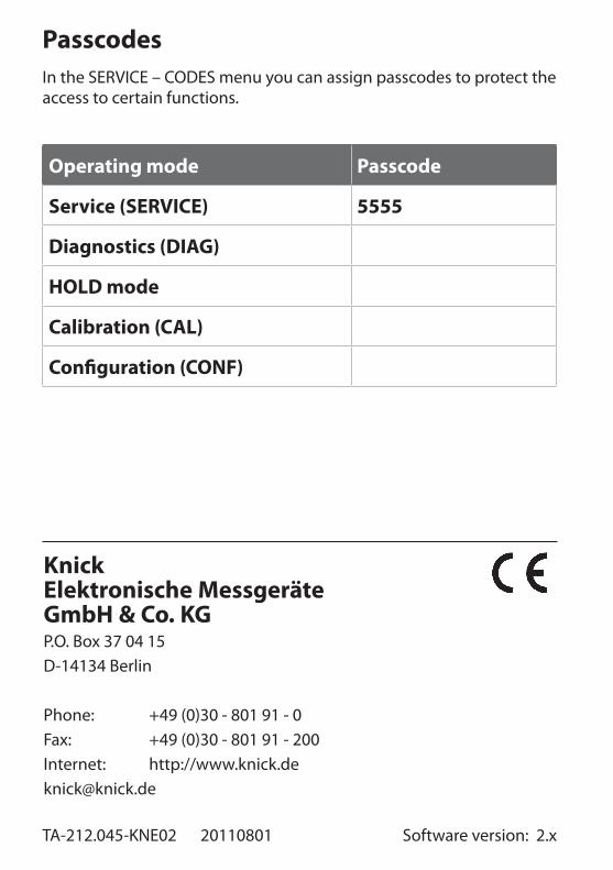
TA-212.045-KNE02 20110801 Software version: 2.x
KnickElektronische Messgeräte GmbH & Co. KGP.O. Box 37 04 15D-14134 Berlin
Phone: +49 (0)30 - 801 91 - 0Fax: +49 (0)30 - 801 91 - 200Internet: http://[email protected]
PasscodesIn the SERVICE – CODES menu you can assign passcodes to protect the access to certain functions.
Operating mode Passcode
Service (SERVICE) 5555
Diagnostics (DIAG)
HOLD mode
Calibration (CAL)
Configuration (CONF)