Embed Size (px)
Citation preview

Stratos
PROFIBUS
2221
X
Oxy
Instruction Manual

Warranty
Defects occurring within 3 years from delivery date shall be remedied
free of charge at our plant (carriage and insurance paid by sender).
Accessories: 1 year
Software release: 2.xDate of issue: 20070810

Contents
Engl
ish
Deu
tsch
1 Information on this instruction manual . . . . . . . . . . . . . . . .3
Markings. . . . . . . . . . . . . . . . . . . . . . . . . . . . . . . . . . . . . . .3
2 Safety information . . . . . . . . . . . . . . . . . . . . . . . . . . . . . . . . .4
Be sure to read and observe the following instructions!. . .4
3 PROFIBUS technology . . . . . . . . . . . . . . . . . . . . . . . . . . . . .5
General . . . . . . . . . . . . . . . . . . . . . . . . . . . . . . . . . . . . . . .5
Variants and basic characteristics . . . . . . . . . . . . . . . . . . .5
Definitions for PROFIBUS-PA . . . . . . . . . . . . . . . . . . . . . .6
PROFIBUS-PA with Stratos . . . . . . . . . . . . . . . . . . . . . . . .6
4 Description . . . . . . . . . . . . . . . . . . . . . . . . . . . . . . . . . . . . . . .7
Proper use . . . . . . . . . . . . . . . . . . . . . . . . . . . . . . . . . . . . .7
Technical features . . . . . . . . . . . . . . . . . . . . . . . . . . . . . . .7
Communication model . . . . . . . . . . . . . . . . . . . . . . . . . . . .8
Profile for process control devices (extract) . . . . . . . . . . . .9
5 Assembly . . . . . . . . . . . . . . . . . . . . . . . . . . . . . . . . . . . . . . .11
Package contents and unpacking . . . . . . . . . . . . . . . . . .11
Mounting plan. . . . . . . . . . . . . . . . . . . . . . . . . . . . . . . . . .12
6 Installation and connection . . . . . . . . . . . . . . . . . . . . . . . .15
Information on installation . . . . . . . . . . . . . . . . . . . . . . . .15
Terminal assignments . . . . . . . . . . . . . . . . . . . . . . . . . . .17
Overview of the Stratos . . . . . . . . . . . . . . . . . . . . . . . . . .17
Dissolved oxygen measurement . . . . . . . . . . . . . . . . . . .18
7 Commissioning . . . . . . . . . . . . . . . . . . . . . . . . . . . . . . . . . 20
Checklist . . . . . . . . . . . . . . . . . . . . . . . . . . . . . . . . . . . . . 20
8 Operation . . . . . . . . . . . . . . . . . . . . . . . . . . . . . . . . . . . . . . 21
Operation possibilities. . . . . . . . . . . . . . . . . . . . . . . . . . . 21
Operation using keypad on the device . . . . . . . . . . . . . . 22
Mode code . . . . . . . . . . . . . . . . . . . . . . . . . . . . . . . . . . . 24
Safety functions . . . . . . . . . . . . . . . . . . . . . . . . . . . . . . . 24
Mode indicators. . . . . . . . . . . . . . . . . . . . . . . . . . . . . . . . 25
Configuration . . . . . . . . . . . . . . . . . . . . . . . . . . . . . . . . E-26
Calibration. . . . . . . . . . . . . . . . . . . . . . . . . . . . . . . . . . . . 29
Operating tool . . . . . . . . . . . . . . . . . . . . . . . . . . . . . . . E-35
Measurement . . . . . . . . . . . . . . . . . . . . . . . . . . . . . . . . . 35
9 Diagnostics . . . . . . . . . . . . . . . . . . . . . . . . . . . . . . . . . . . . . 36
Sensocheck, Sensoface . . . . . . . . . . . . . . . . . . . . . . . . . 36
PROFIBUS-PA limit monitoring . . . . . . . . . . . . . . . . . . . 37
Error messages . . . . . . . . . . . . . . . . . . . . . . . . . . . . . . E-38
Display messages and PROFIBUS communication . . . . 40
Diagnostics functions . . . . . . . . . . . . . . . . . . . . . . . . . . E-43
10 Maintenance and cleaning . . . . . . . . . . . . . . . . . . . . . . . . 45
Maintenance . . . . . . . . . . . . . . . . . . . . . . . . . . . . . . . . . . 45
Cleaning . . . . . . . . . . . . . . . . . . . . . . . . . . . . . . . . . . . . . 45
11 Appendix . . . . . . . . . . . . . . . . . . . . . . . . . . . . . . . . . . . . . . . 46
Product line . . . . . . . . . . . . . . . . . . . . . . . . . . . . . . . . . . . 46
Contents E-1

Specifications . . . . . . . . . . . . . . . . . . . . . . . . . . . . . . . . . 46
ATEX EC-Type-Examination Certificate . . . . . . . . . . . . . 51
Declaration of Conformity . . . . . . . . . . . . . . . . . . . . . . . . 54
FM Control Drawing . . . . . . . . . . . . . . . . . . . . . . . . . . . . 55
12 Index . . . . . . . . . . . . . . . . . . . . . . . . . . . . . . . . . . . . . . . . . . 57
Contents E-2

Information on this instruction manual
E-
3
Engl
ish
1
Information on this instruction manual
1.1
Markings
Operating instructions
•
Each operating instruction is preceded by a dot.
Enumerations
-
Each enumeration is preceded by a dash.
Model designation
For practical purposes, the Stratos
PROFIBUS 2221 X Oxy is simply referred to as Stratos in this instruction manual.
Trademarks
The following names are registered trademarks. For practical reasons
they are shown without trademark symbol in this manual.
- Registered trademarks
- Stratos
®
-
Sensocheck
®
-
Sensoface
®
-
Calimatic
®
-
GainCheck
®
-
InPro
®
InPro
®
is a registered trademark of Mettler Toledo.
The warning symbol means that the
instructions given must always be fol-lowed for your own safety.Failure to follow these instructions may result in injuries
Notes provide important information that
should be strictly followed when using the device.
When a key is shown, its function is explained.
When a display is shown, the corresponding information or operating instructions are pro-vided.

E-
4
Safety information
2
Safety information
2.1
Be sure to read and observe the following instructions!
The device has been designed in accordance with the state of the art
and complying with the applicable safety regulations.
When operating the device, certain conditions may nevertheless lead to danger for the operator or damage to the device.
The protection is likely to be impaired if, for example:
- the device shows visible damage
- the device fails to perform the intended measurements
- after prolonged storage at temperatures above 70 ˚C
- after severe transport stress
Before recommissioning the device, a professional routine test in accordance with EN 61010-1 must be performed. This test should be carried out by the manufacturer.
The Stratos
PROFIBUS 2221 X Oxy may be operated in accordance with the FISCO model.
Whenever it is likely that protection has
been impaired, the device shall be made inoperative and secured against unin-tended operation.
Stratos
PROFIBUS 2221 X Oxy is approved for installation in ATEX, FM Zone 1 with measurement in Zone 0, and FM Class I Div 1. Before commissioning it must be proved that the intrinsic safety is maintained when connecting the device to other equipment, such as segment coupler and cable.
For hazardous-area applications, the
Stratos PROFIBUS 2221 X Oxy may only be connected to explosion-proof segment couplers, power supplies ....
The stipulations of EN 60079-10: 1996 and
the following must be observed for the installation.
In hazardous locations the Stratos may
only be cleaned with a damp cloth to pre-vent electrostatic discharge.

Engl
ish
3 PROFIBUS technology
3.1 General
PROFIBUS is a digital communication system that connects different field devices over a common cable and integrates them into a control system. In the long term, PROFIBUS will replace the 4-20 mA tech-nology, which only supplies pure measured values.
Advantages of the PROFIBUS technology are:
- easy and cost-saving cabling
- convenient operation over a central control station
- transmission, evaluation and control of high amounts of data from field device to control station.
- devices installed in hazardous locations are configured and main-tained from the control station
PROFIBUS is the leading open fieldbus system in Europe. Its applica-tion range covers manufacturing, process and building automation. As open fieldbus standard to EN 50170, PROFIBUS ensures communi-cation of different devices over one bus.
The PROFIBUS User Organization (PNO) provides for further devel-opment and maintenance of the PROFIBUS technology. It combines the interests of users and manufacturers.
3.2 Variants and basic characteristics
PROFIBUS determines the technical and functional characteristics of a serial bus system.
There are three PROFIBUS variants:
- PROFIBUS-FMS (FMS protocol)
- is particularly suited for exchanging large amounts of data between control devices. It operates according to the RS 485 standard with transmission rates up to 12 MBits/sec.
- PROFIBUS-DP (decentralized peripherals)
- is tailored for communication of automation systems and dis-tributed peripherals. It operates according to the RS 485 stan-dard with transmission rates up to 12 MBits/sec.
- PROFIBUS-PA (process automation)
- is dedicated to the process industry. It permits connection of sensors and actuators to a common bus even in hazardous locations. PROFIBUS-PA has a transmission rate of 31.25 kBits/sec.
PROFIBUS distinguishes between two types of devices:
- Masters
- control the data traffic on the bus. They send messages without external request.
- Slaves
- are peripheral devices such as valves, drives, transmitters and analyzers. They can react acyclically to servicing, configuration and diagnostic tasks of the master. The central controller cycli-cally reads the measurement data with status.
PROFIBUS technology E-5

3.3 Definitions for PROFIBUS-PA
The bus protocol defines type and speed of the data exchange between master and slave devices and determines the transmission protocol of the respective PROFIBUS system.
PROFIBUS-PA permits cyclic and acyclic services.
- Cyclic services are used for transmission of measurement data and actuating commands with status information.
- Acyclic services are used for device configuration, maintenance and diagnostics during operation.
The device profile defines the device class and typical functionalities with parameters, ranges and limit values.
The FISCO model developed by the German PTB for hazardous loca-tions permits connection of several devices to one common bus and defines permissible limits for device and cable parameters.
3.4 PROFIBUS-PA with Stratos
Fig. 3.1 Typical configuration of a PROFIBUS system with Stratos
Bus termination
lSlave n
Cyclicservices
Service/Configuration
Acyclicservices
Process control
Segmentcoupler
PROFIBUS-DP
PROFIBUS-PA
lSlave 1 lSlave 2
Stratos
cal conf enter
man
053491
confmeas cal
A P P R O V E D
PTB No.Ex-97.D.XXXXCSA No.XXXXXXXXXloop powered 4 to 20 mA No. 0534911234567
2201 X pH
FM
IS, Class I, Div 1, Group A, B, C, D T4/T6Operating temperature -20 to +55 °C
EEx ib [ia] IIC T4/T6Made in Germany
Stratos
cal conf enter
man
053491
confmeas cal
A P P R O V E D
PTB No.Ex-97.D.XXXXCSA No.XXXXXXXXXloop powered 4 to 20 mA No. 0534911234567
2201 X pH
FM
IS, Class I, Div 1, Group A, B, C, D T4/T6Operating temperature -20 to +55 °C
EEx ib [ia] IIC T4/T6Made in Germany
Stratos
cal conf enter
man
053491
confmeas cal
A P P R O V E D
PTB No.Ex-97.D.XXXXCSA No.XXXXXXXXXloop powered 4 to 20 mA No. 0534911234567
2201 X pH
FM
IS, Class I, Div 1, Group A, B, C, D T4/T6Operating temperature -20 to +55 °C
EEx ib [ia] IIC T4/T6Made in Germany
MasterClass 2
MasterClass 1
E-6 PROFIBUS technology

Engl
ish
4 Description
4.1 Proper use
Stratos is a PROFIBUS-PA analyzer. The Stratos is used for dissolved oxygen and temperature measurement in biotechnology, pharmaceu-tical industry, as well as in the field of environment, food processing and sewage treatment.
The rugged molded enclosure can be wall mounted or fixed into a control panel. It can also be mounted at a post or pipe.
The protective hood provides additional protection against direct weather exposure and mechanical damage.
The unit can be easily replaced since the terminals are of a plug-in design.
The Stratos has been designed for application with amperometric sensors.
4.2 Technical features
Communication between measuring point and control room is via PROFIBUS-PA. The data exchange (cyclic and acyclic) is performed
in accordance with the PROFIBUS-DP/V1 protocol.
Fig. 4.1 System functions (hardware)
Description E-7

4.3 Communication model
The device performance is described by function blocks according to the PNO profile for Process Control Devices.
The respective blocks contain different parameters and functions.
Fig. 4.2 Communication model Stratos PROFIBUS 2221 X Oxy according to the Profile for Process Control Devices (PNO)
Stratos PROFIBUS 2221 X Oxy
E-8 Description

Engl
ish
4.4 Profile for process control devices (extract)
Type of block Block contents (general)
Block contents (detailed)
Physical Block (PB)
Device description Measurement procedure, device configuration
Serial number, manufacturer name
Operating state (run, maintenance, ...)
Global status, diagnostics information
Transducer Block (TB)
Measurement proce-dure with interpreta-tion
Process variable (plain text and unit)
Number of measurement ranges (MR), start and end value of MR, active MR
Sampling rate of measured values
Uncorrected measured value with status
Control Transducer Block
Control of device functions
Status of function execution of respective Transducer Blocks
Calibration data
Transfer Trans-ducer Block
Pre-processing of a measured value
Measured value pre-processing
Temperature compensation
Selection of processing function
Transducer Limit Block
Limit monitoring Block (TB) for limit setting
Threshold, effective direction, hysteresis
On-delay, off-delay
Reset behavior, reset confirmation
Limit status (active, not active)
Description E-9

Tab. 4.1: Profile for Process Control Devices (function contents)
Analog Input (AI)
Function Block
Measured value Currently measured value with status and scale
Rise time, hysteresis of AI limits
Upper/lower alarm limit
Upper/lower warning limit
Switchover manual/automatic operation, measured value simulation
Fail-safe behavior
Discrete Input (DI)
Function Block
Digital input Switchover manual/automatic operation
Limit value message/status
Signal inversion
Fail-safe behavior
Transducer Alarm Block
Signaling of states and events
Required maintenance, function check, errors, limit values incl. summing
Logbook Func-tion Block
Registration of states and events
Power on, power off, reset
State of execution
Navigation through entries
Type of block Block contents (general)
Block contents (detailed)
E-10 Description

Engl
ish
5 Assembly
5.1 Package contents and unpacking
Unpack the device carefully. Check the shipment for transport damage and completeness.
The package should contain:
- Front unit of Stratos
- Lower case
- This instruction manual
- Short instruction sheet
- Floppy disk with GSD file KNIC7533.GSD
- Bag containing small parts:
Fig. 5.1 Assembling the enclosure
1 Jumper (2 piece)
2 Washer (1 piece): for conduit mount-ing: Place washer between enclosure and nut
3 Cable ties (3 pieces)
4 Hinge pin (1 piece): insertable from either side
5 Enclosure screws (4 pieces)
6 Sealing inserts (3 pieces)
7 Rubber reducer (1 piece)
8 Cable glands (3 pieces)
9 Filler plugs (3 pieces)
10 Gaskets (3 pieces)
11 Hexagon nuts (3 pieces)
12 Sealing plugs (2 pieces): for sealing in case of wall mounting
Assembly E-11

5.2 Mounting plan
Fig. 5.2 Mounting plan
1 Cable gland (3 pieces)
2 Breakthroughs for cable gland or conduit 1/2“, ø = 21.5 mm (2 breakthroughs)
Cable glands and conduits not included!
3 Breakthroughs for pipe mounting (4 breakthroughs)
4 Breakthroughs for wall mounting (2 breakthroughs)
E-12 Assembly

Engl
ish
Fig. 5.3 ZU 0275 panel-mount kit, panel cutout 138 x 138 mm (DIN 43700)
Fig. 5.4 ZU 0274 pipe-mount kit
1 Screws (4 pieces)
2 Gasket (1 piece)
3 Panel
4 Span pieces (4 pieces)
5 Threaded sleeves (4 pieces)
1 ZU 0276 protective hood (if required)
2 Hose clamps with worm gear drive to DIN 3017 (2 pieces)
3 Pipe-mount plate (1 piece)
4 For vertical or horizontal posts or pipes
5 Self-tapping screws (4 pieces)
Assembly E-13
Fig. 5.5 ZU 0276 protective hood for wall and pipe mounting
1 Protective hood
E-14 Assembly

Engl
ish
6 Installation and connection
6.1 Information on installation
For easier installation, the terminal strips are of a plug-in design. The terminals are suitable for single wires and flexible leads up to 2.5 mm2 (AWG 14).
A special twisted and shielded two-wire cable (e.g. Siemens) is used as bus cable.
Division 2 wiring
The connections to the Transmitter must be installed in accordance with the National Electric Code (ANSI-NFPA 70) Division 2 hazardous (classified) location non-incendive wiring techniques.
Installation may only be carried out by trained experts in accordance with this instruction manual and as per applicable local and national codes.
Be sure to observe the technical specifica -tions and input ratings during installation.
According to the PTB FISCO model, the limits of the permissible parameter range must be observed for connection in a haz-ardous location.See PROFIBUS Technical Guidelines PNO Order No.: 2.091
Be sure not to notch the conductor when stripping the insulation.
Installation and connection E-15

Fig. 6.1 Information on installation
1 Connection leads PROFIBUS-PA
2 Area for placing the screwdriver to pull out the terminals
3 Cover for DO sensor and tempera-ture probe terminals
4 Pulling out the terminal blocks using a screwdriver
5 Recommended stripping lengths for multi-core cables
6 Recommended stripping lengths for coaxial cables
7 Cable laying in the device
E-16 Installation and connection

Engl
ish
6.2 Terminal assignments
Fig. 6.2 Terminal assignments of Stratos
6.3 Overview of the Stratos
Fig. 6.3 Inputs and outputs
1 Inputs for 2 different DO sensors
2 Input for temperature probe
3 PROFIBUS-PA, protected against polarity reversal
2
3
Installation and connection E-17

6.4 Dissolved oxygen measurement
Fig. 6.4 Typical wiring of SE 704/705 or InPro 6000 sensors
A DO sensor
B Temperature probe
bk bk rd wt
E-18 Installation and connection

Engl
ish
Fig. 6.5 Typical wiring of sensors with VP cable
A DO sensor
B Temperature probe
Installation and connection E-19
E-20 Commissioning
7 Commissioning
7.1 Checklist
Commissioning may only be carried out by trained experts.
Before commissioning the Stratos PROFIBUS 2221 X Oxy, the following requirements must be met:
- The device must not show any damage.
- When recommissioning the device after a repair, a professional routine test in accor-dance with EN 61010-1 must be performed.
- It must be proved that the intrinsic safety is maintained when connecting the device to other equipment.
- It must be ensured that the device is config-ured in accordance with the connected peripherals.
- All connected voltage and current sources must correspond to the technical data of the device.
- The device must only be connected to explosion-proof segment couplers, power supplies, ...
Engl
ish
8 Operation
8.1 Operation possibilities
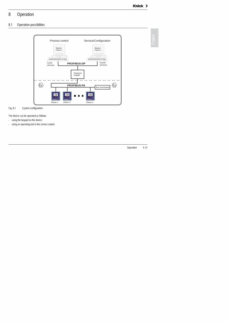
Fig. 8.1 System configuration
The device can be operated as follows:
- using the keypad on the device
- using an operating tool in the service station
Bus termination
lSlave n
Cyclicservices
Service/Configuration
Acyclicservices
Process control
Segmentcoupler
PROFIBUS-DP
PROFIBUS-PA
lSlave 1 lSlave 2
Stratos
cal conf enter
man
053491
confmeas cal
A P P R O V E D
PTB No.Ex-97.D.XXXXCSA No.XXXXXXXXXloop powered 4 to 20 mA No. 0534911234567
2201 X pH
FM
IS, Class I, Div 1, Group A, B, C, D T4/T6Operating temperature -20 to +55 °C
EEx ib [ia] IIC T4/T6Made in Germany
Stratos
cal conf enter
man
053491
confmeas cal
A P P R O V E D
PTB No.Ex-97.D.XXXXCSA No.XXXXXXXXXloop powered 4 to 20 mA No. 0534911234567
2201 X pH
FM
IS, Class I, Div 1, Group A, B, C, D T4/T6Operating temperature -20 to +55 °C
EEx ib [ia] IIC T4/T6Made in Germany
Stratos
cal conf enter
man
053491
confmeas cal
A P P R O V E D
PTB No.Ex-97.D.XXXXCSA No.XXXXXXXXXloop powered 4 to 20 mA No. 0534911234567
2201 X pH
FM
IS, Class I, Div 1, Group A, B, C, D T4/T6Operating temperature -20 to +55 °C
EEx ib [ia] IIC T4/T6Made in Germany
MasterClass 2
MasterClass 1
Operation E-21

8.2 Operation using keypad on the device
Fig. 8.2 Front view of Stratos
1 Display
2 Mode indicators (no keys)
- Measuring mode
- Calibration mode
- Alarm
- PROFIBUS-PA communication
- Configuration mode
3 Keypad
4 Coding
5 Rating plate
6 Model designation
E-22 Operation

Engl
ish
Display
Fig. 8.3 Stratos display
Keypad functions
1 Mode code entry 11 Measurement symbols
2 Display of measured vari-able
12 Proceed with enter
3 Temperature 13 Bar for device status
4 Not connected 14 Lower display
5 Limit values 15 Manual temp indicator
6 Alarm 16 Hold state active
7 Sensocheck 17 Wait
8 Calibration 18 Sensor data
9 Interval/ response time
19 Main display
10 Not connected 20 Sensoface
1 2 3 4 5 6 7 8 9 10
11
12
13
1617
20
18
19
15 14
Measurement
Calibration
Configuration
Select digit positionSelected position flashes
Change digit
Prompt in display: Continue in program sequenceConfiguration: Confirm entries, next configuration step
Further key combinations are explained in the respective function descriptions.
Operation E-23

8.3 Mode code
After pressing meas and/or cal you can enter one of the following mode codes to access the designated mode:
8.4 Safety functions
Sensocheck, Sensoface sensor monitoring
Sensocheck monitors the sensor and lines for short circuits or open connections.
Sensocheck can be switched off.
GainCheck manual device self-test
A display test is carried out, the software version is displayed and the memory and measured value transfer are checked.
Automatic device self-test
The automatic device self-test checks the memory and measured-
value transfer. It runs automatically in the background at fixed inter-vals.
conf, 0000conf, 1200cal, 1001cal, 1105
Error InfoConfiguration modeZero point calibrationProduct calibration
cal, 0000cal, 1015cal, 1100cal, 2222
Cal InfoAdjusting temp probeCalibration modeDisplay sensor current (uncom-pensated)/ temperature
Sensoface provides information on the sensor condition.The zero point, slope and response time dur-ing calibration are evaluated.The three Sensoface indicators provide the user with information about wear and required maintenance of the sensor.
Start GainCheck manual device self-test
E-24 Operation

Engl
ish
Hold state
The Hold state is a safety state that is activated in the case of interven-tions such as configuration and calibration. The Stratos freezes the last valid measured value and sends a status message to the control system.
The Hold state is activated by the following mode codes:
- Calibration
- Mode code 1015 = Temp probe adjustment- Mode code 1100 = Calibration mode- Mode code 2222 = Display of sensor potential
- Configuration
- Mode code 1200 = Configuration modeThe measured value and Hold are displayed alternately
After 20 sec (for measured value stabilization) the device returns to measuring mode.
8.5 Mode indicators
Measuring mode
Calibration mode
Alarm
The alarm response time is permanently set to 10 sec.
PROFIBUS-PA communication
Configuration mode
This symbol indicates that the device is in the “Hold” state.
• Check whether the measured value is plausible
• End the Hold state
The Stratos is in measuring mode.
Calibration mode is active.
During an error message the red alarm LED beneath the display flashes.
The Stratos communicates via PROFIBUS-PA and can be configured from the service station. Measured values, messages and device identification can be downloaded at any time. This allows integration in fully auto-matic process cycles.
The Stratos is in configuration mode.
Operation E-25

8.6 Configuration
In the configuration mode the device parameters are set.
The following steps must be executed:
For configurable parameters, see ”Configuration parameters” Page 27.
• Activate configuration
• Enter mode code “1200”
• Confirm
Welcome text 3 sec
During configuration the Stratos remains in the Hold state for reasons of safety.
• Select or edit parameter
• Confirm entries
The configuration parameters are checked during the input.
In the case of an incorrect input “Err” is dis-played for 3 sec. The incorrect parameters cannot be stored. Input must be repeated.
• End configuration
The measured value and Hold are displayed alternately.
• End the Hold state / accept configuration or
• Repeat configuration
E-26 Operation

Engl
ish
Configuration parameters
Display Action Choices Factory setting
Activate configuration (simultaneously press meas and cal)
Enter mode code “1200” (Press arrow key to select position, enter number using key, confirm with enter)
Device is in Hold state.
• Select sensor (type A / B) Proceed with enter
• Switch over: arrow keys
• Proceed: enter key
Sensor Type A (general sensor)
Sensor Type B (Mettler InPro6900)
Low Level
High Level
Type A
Hi-Level
Selection of variable to be displayed
• Switch over: arrow keys
• Proceed: enter key
With Low Level selected: µg/l • ppb • mg/l • ppm • %
With High Level selected: mg/l • ppm • %
%
Selection of process temp
• Switch over: arrow keys
• Proceed: enter key
man °C / man °F
auto °C / auto °F
BUS °C / BUS °F:
-20 to +150 °C or -4 to +302 °F
Auto °C
Selection of temp probe (NTC)
• Switch over: arrow keys
• Proceed: enter key
Only with Auto selected:
22 kΩ
30 kΩ
22 NTC
Operation E-27
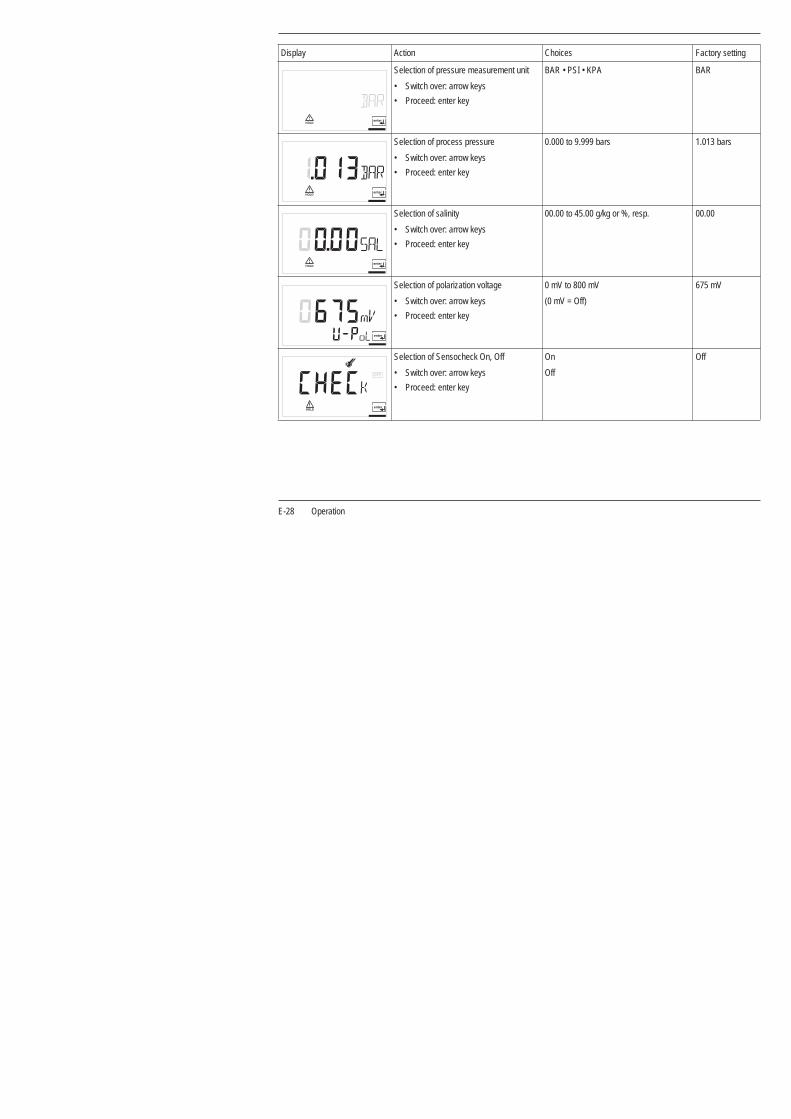
Selection of pressure measurement unit
• Switch over: arrow keys
• Proceed: enter key
BAR • PSI • KPA BAR
Selection of process pressure
• Switch over: arrow keys
• Proceed: enter key
0.000 to 9.999 bars 1.013 bars
Selection of salinity
• Switch over: arrow keys
• Proceed: enter key
00.00 to 45.00 g/kg or %, resp. 00.00
Selection of polarization voltage
• Switch over: arrow keys
• Proceed: enter key
0 mV to 800 mV
(0 mV = Off)
675 mV
Selection of Sensocheck On, Off
• Switch over: arrow keys
• Proceed: enter key
On
Off
Off
Display Action Choices Factory setting
E-28 Operation

Engl
ish
Tab. 8.1: Configuration parameters
Configuration is circular. To stop, press meas key.
8.7 Calibration
Calibration is used to adapt the device to the DO sensor. Depending on the configuration, the device can be calibrated with regard to satu-ration or concentration. For each calibration mode, the Stratos suggests useful calibration parameters. Of course, they can be edited as required.
Note:
When a 2-point calibration is required, the zero point calibration should be performed prior to saturation or concentration calibration, resp.
If calibration is exited, the Stratos remains in the Hold state for reasons of safety. The measured value and Hold are displayed alternately. Now you can check whether the measured value is plausible and
Selection of calibration mode
• Switch over: arrow keys
• Proceed: enter key
- Saturation (Sat)
- Concentration (Conc)
Conc
Selection of cal timer interval 0000 (Off)
Selection of bus address 126
Display Action Choices Factory setting
All calibration procedures must be performed by trained personnel.During calibration, the output current is frozen, limit and alarm contacts are inactive.
Incorrectly set parameters may go unnoticed, but change the measuring properties.
Operation E-29

specifically end the Hold state with enter or press cal to repeat calibra-tion.
If you end the Hold state, the Stratos will return to measuring mode after 20 sec (for the sensor to adjust).
Zero point calibration
A zero point calibration is not required for most of the biotechnological processes. For these processes, we recommend to set the input current for the zero point to 0.0 nA and then perform a one-point cali-bration (saturation). If a zero point calibration is performed, the DO
sensor should remain for at least 10 to 30 minutes in the calibration medium in order to obtain accurate values. A drift check is not performed.
Zero point current should be < 0.5 % of air current. The display (secondary: measured value, main: entered value) does not change until an input current is entered for the zero point.
When measuring in an oxygen-free medium, the displayed current can be taken directly.
When the zero point has changed, the slope is automatically adjusted so that the 100% point remains valid.
Saturation calibration
Display Zero point calibration – Action Selection / Remarks
• Activate calibration (press cal key)
1001 • Enter mode code “1001” (Press arrow key to select position, enter number using key, confirm with enter)
• Place sensor in oxygen-free medium
Lower display: actually measured current
Main display: value for zero point.
• Confirm with enter or correct using arrow keys and then confirm with enter
Display of slope
Display of new zero point
• Place sensor in process
• End calibration with enter
After end of calibration, the Stratos remains in Hold state for approx. 20 sec.
The oxygen value is displayed.
E-30 Operation

Engl
ish
Display Action Selection / Remarks
Select calibration, enter mode code “1100” cal key, arrow keys
• Enter relative humidity Default for aqueous media rH = 100 %
Proceed with enter
• Enter calibration pressure, proceed with enter Default: configured process pressure
• If temperature display follows, temperature can be entered manually, see remarks
• Proceed with enter
If "man" or "BUS" has been selected dur-ing configuration, the configured process temperature will be displayed. The internal temperature probe is not used.
• Automatic drift check: Measurement Display of input current (temperature-compensated) and of measuring temp
Drift check can be stopped after > 10 sec by pressing cal (accuracy reduced).
• Change default value if required Default: last value entered
• Display of new slope and zero point related to 25°C at 1013 mbars
• End calibration with enter
After end of calibration, the oxygen value is displayed for approx. 20 sec. Then the Stratos will return to measuring mode.
Operation E-31

Concentration calibration
Display Action Selection / Remarks
Select calibration, enter mode code “1100” cal key, arrow keys
Place DO sensor in air for calibration
• Enter relative humidity
• Proceed with enter
Default for aqueous media rH = 50 %
• Enter calibration pressure, proceed with enter
• If temperature display follows, temperature can be entered manually, see remarks
• Proceed with enter
Default: normal pressure 1013 mbars. If "man" or "BUS" has been selected during configuration, "25 °C" will be displayed. The internal temperature probe is not used.
• Measurement Display of input current (temperature-compensated) and of measuring temp
Drift check can be stopped after > 10 sec by pressing cal (accuracy reduced).
• Default value calculated from rel. humidity, cal pressure and cal temp (theoretical concentration for saturation)
Edit default value if required.
Display of new slope and zero point related to 25°C at 1013 mbars
• End calibration with enter
After end of calibration, the oxygen value is displayed for approx. 20 sec. Then the Stratos will return to measuring mode.
E-32 Operation

Engl
ish
Product calibration
Display Action Selection / Remarks
Select calibration, enter mode code “1105” cal key, arrow keys
Product calibration 1st step Display (approx. 3 sec)
• Take sample and store value
• Proceed with enter
Now the sample can be measured in the lab. The Stratos is in measuring mode.
• Measuring mode While the sample value is determined, the device is in measur-ing mode. From the flashing CAL mode indicator you see that sample calibration has not been terminated.
• When the sample value has been determined, call up the prod-uct calibration once more (CAL key, mode code 1105). Product calibration 2nd step
Display (approx. 3 sec)
Enter lab value. The new slope is calculated. Then zero point and slope are displayed as for ordinary calibration.
Arrow keys
Operation E-33

Adjusting temp probe
The following steps must be executed:
Wrong settings change the measurement properties!
• Activate calibration
• Enter mode code “1015” and confirm
• Measure the temperature of the process medium using an external thermometer
A welcome text ("CAL TMP") is displayed for 3 sec.
• Then enter the determined temperature value in the main display (arrow keys)
If the value of the main display is set to the value of the secondary display, a correction is not made.
• Confirm with enter
HOLD will be deactivated after 20 sec.
E-34 Operation

Engl
ish
8.8 Operating tool
For parameter setting, commissioning and diagnostics of the Stratos via PROFIBUS, we recommend operating tools such as SIMATIC-PDM Version 5 or higher.
The current device description is included.
8.9 Measurement
Measuring mode
In the measuring mode the main display shows the configured process variable and the lower display the temperature.
Cal Info
“Cal Info” shows the slope and zero point current.
“Cal Info” shows the current calibration data for approx. 20 sec.
Error Info
“Error Info” shows the most recent error message.
The error message is displayed for approx. 20 sec. After that the message will be deleted.
The Stratos returns to measuring mode, also from configuration or calibration mode (after a relax time for measured-value stabilization, if required).
• Activate “Cal Info” function
• Mode code
• Confirm
• End “Cal Info”
• Activate “Error Info” function
• Mode code
• Confirm
• End “Error Info”
Operation E-35

9 Diagnostics
9.1 Sensocheck, Sensoface
Three Smileys provide information on wear and required maintenance. This does not affect the measurement process.
Sensoface displays
Sensoface provides information on the status of the sensor.The zero point, slope and response time dur-ing calibration are evaluated.A Smiley can only be displayed when Sen-socheck has been activated.
The basis for accurate Sensoface indication is proper calibration.
The worsening of a Sensoface criterion leads to the devaluation of the Sensoface indicator (average/poor).
An improvement of the Sensoface indicator can only take place after calibration or removal of a sensor defect.
The Sensoface status does not influence the measured value display.
Display Problem Status
Sensor response time The sensor adjusts slowly to the measured value. Maybe it has not been polarized sufficiently. You should consider replacing the membrane module and electrolyte.
The sensor adjusts very slowly to the measured value. Correct measurement is no longer ensured. If this occurs in spite of sufficient polarization, you should replace the membrane module and electrolyte.
Slope Sensor slope is still okay. However, membrane module and electrolyte should be replaced soon.
Sensor slope has reached a value which no longer ensures proper measurement. You should replace membrane module and electrolyte.
E-36 Diagnostics

Engl
ish
Tab. 9.1: Sensoface display
9.2 PROFIBUS-PA limit monitoring
Stratos is equipped with two limit blocks that can be separately config-ured for temperature and/or the process variable.
Configuration is only performed via the bus.
The limit conditions are transmitted cyclically.
Hysteresis, effective direction, on and off delay can be configured.
Calibration timer Over 80 % of the calibration interval has already past.
The calibration interval has been exceeded.
Sensor defect Check membrane module and electrolyte and the sensor connections.
Display Problem Status
Limit value setting and output of limit mes-sages is via the PROFIBUS-PA.
When this symbol is displayed, limit block 1 is active.
When this symbol is displayed, limit block 2 is active.
Diagnostics E-37

9.3 Error messages
When one of the following error messages is displayed, the device can no longer determine the measured variable correctly.
The alarm response time is permanently set to 10 sec.
Tab. 9.2: Error messages
During an error message the red alarm LED beneath the display flashes.
The error messages in the display are sorted according to their priority. A higher-priority message overlays a lower-priority message.
Error No. Display (flashing) Problem Possible causes
Err 01 DO sensor - Sensor defect
- Incorrect sensor connected
- Measurement range (%) exceeded Current range (mA) exceeded
Err 02 DO sensor - Sensor defect
- Measured concentration value lower than 0 mg/l (ppm) or higher than 50 mg/l (ppm)
Err 03 Temperature probe - Open or short circuit in temperature probe
- Measured temperature below -10 °C or above +150 °C
Err 33 DO sensor - Membrane defective
Err 98 System error - Configuration or calibration data defective; completely reconfigure and recalibrate the device
- Memory error in device program (PROM defective)
Err 99 Factory settings - EEPROM or RAM defective
This error message only occurs in the case of a complete defect. The Stratos must be repaired and recalibrated at the factory.
E-38 Diagnostics

Engl
ish
Calibration error messages
Tab. 9.3: Calibration error messages
Calibration error messages only occur during calibration.
Display (flashing) Problem Possible causes
Sensor slope out of range - Wrong calibration values specified (relative humidity, pressure, saturation, concentra-tion)
Calibration was canceled after approx. 12 minutes, because the sensor drift was too large.
- Sensor defective or dirty
- No electrolyte in the sensor
- Sensor cable insufficiently shielded or defective
- Strong electric fields influence the measurement
- Temperature fluctuation of calibration solution
Diagnostics E-39
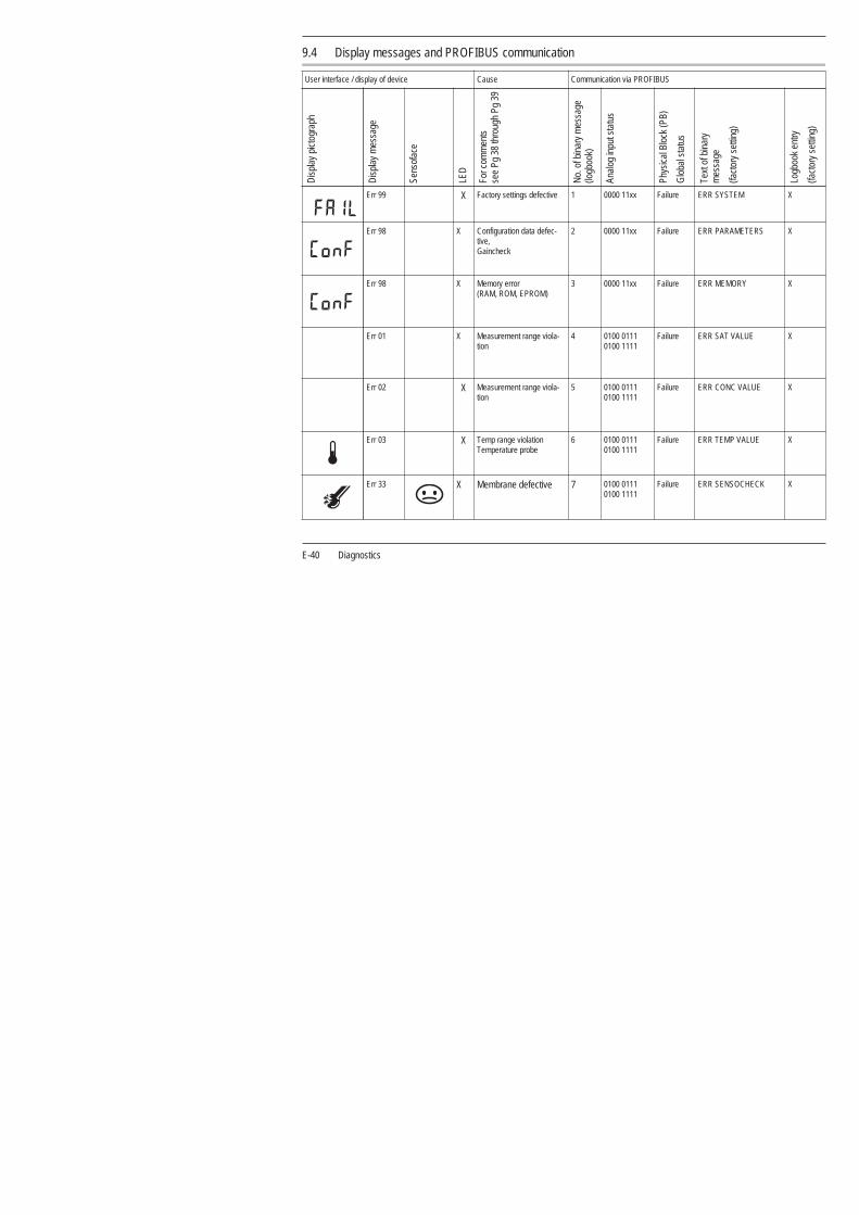
9.4 Display messages and PROFIBUS communication
User interface / display of device Cause Communication via PROFIBUS
Dis
play
pic
togr
aph
Dis
play
mes
sage
Sens
ofac
e
LED
For c
omm
ents
see
Pg 3
8 th
roug
h Pg
39
No.
of b
inar
y m
essa
ge
(logb
ook)
Anal
og in
put s
tatu
s
Phys
ical
Blo
ck (P
B)
Glo
bal s
tatu
s
Text
of b
inar
y
mes
sage
(fact
ory
setti
ng)
Logb
ook
entry
(fact
ory
setti
ng)
Err 99 X Factory settings defective 1 0000 11xx Failure ERR SYSTEM X
Err 98 X Configuration data defec-tive, Gaincheck
2 0000 11xx Failure ERR PARAMETERS X
Err 98 X Memory error (RAM, ROM, EPROM)
3 0000 11xx Failure ERR MEMORY X
Err 01 X Measurement range viola-tion
4 0100 0111 0100 1111
Failure ERR SAT VALUE X
Err 02 X Measurement range viola-tion
5 0100 0111 0100 1111
Failure ERR CONC VALUE X
Err 03 X Temp range violation Temperature probe
6 0100 0111 0100 1111
Failure ERR TEMP VALUE X
Err 33 X Membrane defective 7 0100 0111 0100 1111
Failure ERR SENSOCHECK X
E-40 Diagnostics

Engl
ish
Zero point/ Slope
8 0101 00xx Mainte-nance required
CHK ZERO/SLOPE X
Sensor response time 9 0101 00xx Mainte-nance required
CHK EL. RESPONSE X
Calibration timer Cal prompt
10 0101 00xx Mainte-nance required
CAL REQUIRED X
Calibration 11 0100 0111 0100 1111
Function check
CAL RUNNING X
Configuration 12 0100 0111 0100 1111
Function check
CONF RUNNING X
HOLD (Device state = Mainte-nance)
13 0100 0111 0100 1111
Function check
HOLD X
HI_HI_LIM FB analysis
14 1000 1110 Limit 1 Bit 1
HI_HI_LIMIT OXY
HI_LIM FB analysis
15 1000 1010 Limit 1 Bit 2
HI_LIMIT OXY
LO_LIM FB analysis
16 1000 1001 Limit 1 Bit 3
LO_LIMIT OXY
User interface / display of device Cause Communication via PROFIBUS
Dis
play
pic
togr
aph
Dis
play
mes
sage
Sens
ofac
e
LED
For c
omm
ents
see
Pg 3
8 th
roug
h Pg
39
No.
of b
inar
y m
essa
ge
(logb
ook)
Anal
og in
put s
tatu
s
Phys
ical
Blo
ck (P
B)
Glo
bal s
tatu
s
Text
of b
inar
y
mes
sage
(fact
ory
setti
ng)
Logb
ook
entry
(fact
ory
setti
ng)
Diagnostics E-41

Tab. 9.4: Display messages and PROFIBUS communication
LO_LO_LIM FB analysis
17 1000 1101 Limit 1 Bit 4
LO_LO_LIMIT OXY
HI_HI_LIM FB temperature
18 1000 1110 Limit 2 Bit 1
HI_HI_LIMIT TEMP
HI_LIM FB temperature
19 1000 1010 Limit 2 Bit 2
HI_LIMIT TEMP
LO_LIM FB temperature
20 1000 1001 Limit 2 Bit 3
LO_LIMIT TEMP
LO_LO_LIM FB temperature
21 1000 1101 Limit 2 Bit 4
LO_LO_LIMIT TEMP
Logbook empty 22 Function check
EMPTY LOGBOOK
User interface / display of device Cause Communication via PROFIBUS
Dis
play
pic
togr
aph
Dis
play
mes
sage
Sens
ofac
e
LED
For c
omm
ents
see
Pg 3
8 th
roug
h Pg
39
No.
of b
inar
y m
essa
ge
(logb
ook)
Anal
og in
put s
tatu
s
Phys
ical
Blo
ck (P
B)
Glo
bal s
tatu
s
Text
of b
inar
y
mes
sage
(fact
ory
setti
ng)
Logb
ook
entry
(fact
ory
setti
ng)
E-42 Diagnostics

Engl
ish
9.5 Diagnostics functions
Cal Info
“Cal Info” shows the slope and zero point current.
The current calibration data are displayed for approx. 20 sec.
Error Info
“Error Info” shows the most recent error message.
The error message is displayed for approx. 20 sec. After that the message will be deleted.
Display of sensor current
During sensor maintenance it is useful to directly indicate the sensor current. This allows, for example, to check sensor response after cleaning.
The sensor current is displayed.
• Activate “Cal Info” function
• Mode code
• Confirm
• End “Cal Info”
• Activate “Error Info” function
• Mode code
• Confirm
• End “Error Info”
This symbol indicates that the temperature will be manually specified.
• Select function
• Enter mode code “2222”
• Confirm
• End display mode
During sensor current display the Stratos is in the Hold state.
Diagnostics E-43

GainCheck manual device self-test
A display test is carried out, the software version is displayed and the memory and measured value transfer are checked.
Automatic device self-test
The automatic device self-test checks the memory and measured-value transfer. It runs automatically in the background at fixed inter-vals.
• Start GainCheck manual device self-test
E-44 Diagnostics

Maintenance and cleaning E-45
Engl
ish
10 Maintenance and cleaning
10.1 Maintenance
The Stratos contains no user repairable components.
10.2 Cleaning
To remove dust, dirt and spots, the external surfaces of the Stratos may be wiped with a soft cloth moistened with water.
A mild household cleaner may also be used if necessary.

11 Appendix
11.1 Product line
Devices Mounting accessories
11.2 Specifications
General specifications
Applications
Model designation Ref. No.
Stratos PROFIBUS 2221 X Oxy for hazard-ous- and safe-area applications
2221 X Oxy
Accessories Ref. No.
Pipe-mount kit ZU 0274
Panel-mount kit ZU 0275
Protective hood ZU 0276
Manufacturer / ID Knick Elektronische Meßgeräte GmbH / KNIC
Model designation / ID
Stratos PROFIBUS 2221 X Oxy / 2533
Measurement of dissolved oxygen and temperature
E-46 Appendix

Engl
ish
DO input Input for SE704/SE705, Inpro6000 dissolved oxygen sensors
Range 1
(low level)
Measuring current -2 to +600 nA, resolution 10 pA
Saturation (-10 °C to +80 °C) 0.0 to 120.0 %
Meas. error1,2,3 0.5 % meas. value + 0.1 % saturation
Concentration (-10 °C to +80 °C)
0000 to 9999 µg/l
0000 to 9999 ppb
0000 to 9999 ppm
0000 to 9999 mg/l
Meas. error1,2,3 0.5 % meas. value + 5 µg/l or 5 ppb, resp.
Range 2
(high level)
Measuring current -2 to +1800 nA, resolution 30 pA
Saturation (-10 °C to +80 °C) 0 to 500 %
Meas. error1,2,3 0.5 % meas. value + 0.5 % saturation
Concentration (-10 °C to +80 °C)
0.0 to 50.00 mg/l
0.0 to 50.00 ppm
Meas. error1,2,3 0.5 % meas. value + 50 µg/l or 50 ppb, resp.
Polarization voltage 0 to 1000 mV
Process pressure 0.000 to 9.999 bars
999.9 kPa
145.0 psi
Salt correction 0.00 to 45.00 g/kg
Sensocheck Monitoring for short circuits or open circuits (can be disabled)
Appendix E-47

*) Configurable1) To IEC 746 Part 1, at nominal operating conditions
2) ± 1 count3) Plus sensor error
Sensor standardization (cal) Zero point calibration Calibration with entry of oxygen saturation Calibration with entry of oxygen concentration at saturation Product calibration
Calibration range Zero ± 2 nA
Slope Sensor Type A: 25 to 130 nA Sensor Type B: 200 to 550 nA (Mettler-Toledo InPro6900)
Cal timer* 0 to 9999 h
Pressure correction Calibration pressure to be entered manually or via PROFIBUS
Temperature input NTC 22kΩ or NTC 30 kΩ, 2-wire connection, ± 5 K adjustable
Range -20.0 to +150.0 °C / -4 to +302 °F
Resolution 0.1 °C / 1 °F
Meas. error1,2,3 < 0.5 K (< 1 K bei > 100 °C)
Temperature compensation Automatic with NTC or manual temperature
Logbook Recording of error messages
Storage capacity 40 entries, can be read out via Profibus (see profile description)
Limit values Cyclical discrete signal (DI) via Profibus (see profile description) User-defined via Profibus for: Oxygen saturation Oxygen concentration Temperature
Alarms and messages Binary messages to PNO profile 3.0 Signalling via PROFIBUS and logbook entry
E-48 Appendix

Engl
ish
Conditions for use
Construction
Temperature Operation -20 to +55 °C
Transport and storage -20 to +70 °C
Electromagnetic compatibility Emitted interference EN 61 326 Class B
Immunity to interference EN 61 326, EN 61 326/A1
Ingress protection Enclosure IP 65
Explosion protection PROFIBUS-PA according to FISCO model of PTB
II 2(1) G EEx ia IIC T4, FISCO
FM IS, Class I Div1, Group A, B, C, D T4 FISCO I / 1[0] / AEx ib [ia] / IIC / T4 FISCO NI, Class I Div2, Group A, B, C, D T4 NIFW
Data retention Parameters and calibration data > 10 years EEPROM
Dimensions Height 144 mm
Width 144 mm
Depth 105 mm
Weight Approx. 1 kg
Material PBT (polybutylene terephtalate)
Color Bluish gray RAL 7031
Assembly Wall mounting
Post/pipe mounting on pipe with 40 to 60 mm diameter, on square post with 30 to 45 mm edge length
Panel mounting Cutout to DIN 43 700
Sealed against panel
Electrical connection Cable glands 3 breakthroughs for included cable glands
2 breakthroughs for NPT 1/2” or Rigid Metallic Conduit or cable glands
Appendix E-49

Display and user interface
Interface
Display LC display, 7-segment Measured value display µg/l, mg/l, ppb, ppm, %, temperature
3 Sensoface states Good / average / poor
5 mode indicators meas / cal / alarm / online / conf
Alarm LED Error message
Operation 5 keys meas / cal / up / right / enter
Operating tool Device description (DD) implemented in SIMATIC PDM
PROFIBUS-PA com-munication
Digital communication by current modulation of supply current Reading of device identification, measured values, status and message Reading and writing of parameter and configuration data
Protocol PROFIBUS-PA (DPV1)
Connection Via segment coupler to SPC, PC, PCS
Profile PNO directive: PROFIBUS-PA, Profile for Process Control Devices, Version 3.0
Physical interface
To IEC 1158-2
Address range 1 to 126, default: 126
Supply voltage FISCO bus supply: 9 to 17.5 V Linear barrier: 9 to 24 V
Current consumption < 13.2 mA
Max. current in case of fault (FDE)
< 17.6 mA
E-50 Appendix

Engl
ish
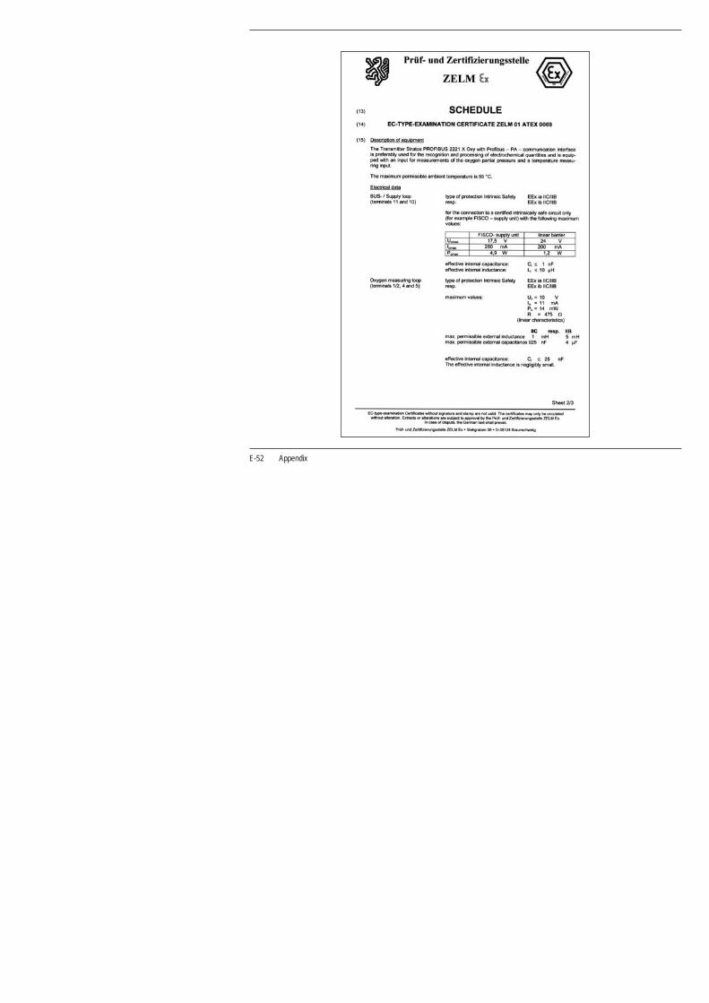
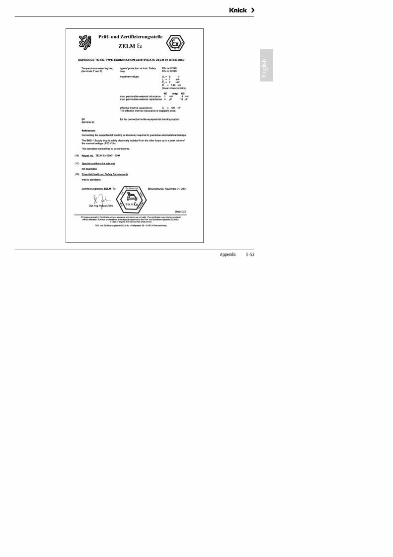
11.3 ATEX EC-Type-Examination Certificate
Appendix E-51
E-52 Appendix
Engl
ish
Appendix E-53

11.4 Provided documentation:
• Instruction manual
• Short instructions
• Safety instructions / • EC Declarations of Conformity
• EC-Type Examination Certificate
70084
XXXX (X)Bedienungsanleitung
Stratos®
XXXX X
Safety precautions . . . . . . . . . . . . . . 3Sicherheitshinweise . . . . . . . . . . . . . 5Consignes de sécurité . . . . . . . . . . . 7Norme di Sicurezza . . . . . . . . . . . . . . 9Avisos de seguridad . . . . . . . . . . . . 11Turvallisuusohjeet . . . . . . . . . . . . . . 13Säkerhetsanvisningar . . . . . . . . . . . 15Sikkerhetsinstrukser. . . . . . . . . . . . 17Veiligheidsvoorschriften. . . . . . . . . 19Sikkerhedshenvisninger. . . . . . . . . 21Indicações de segurança . . . . . . . . 23Sigurnosne upute . . . . . . . . . . . . . . 25Saugumo nurodymai. . . . . . . . . . . . 27Wskazówki dotyczącebezpieczeństwa 29Указания по безопасности . . . . . . 31Bezpečnostní pokyny . . . . . . . . . . . 33Biztonsági tudnivalók . . . . . . . . . . . 35
Stratos®
CAL CA. Sol(BUF)
1100 1100
CAL CA. Sol(MAN)
Meß-Modus / Measuring mode / Mode mesure
Kalibrierung / Calibration / Calibrage
AutomatischAutomaticAutomatique
ManuellManualManuel
Cal-InfoKalibrierungProduktkalibrierungVerschiebung Nullpkt.Temp. AbgleichLetzter FehlerKonfigurierungSensormonitorStromgeber 1Stromgeber 2RelaistestRegler manuellParametersatz 1/2Paßzahl-Editor *
FehlermeldungenSteilheit /Asymmetriepotential
Drift der Meßkette
Pufferlösung
Meßbereich pH
Meßbereich mV
Temperatur
Ausgangsstrom 1zu kleinzu großSpanneAusgangstrom 2zu kleinzu großSpanneSensocheckGlaselektrodeBezugselektrodeSpülsondeKommunikationCal-Fehler
Cal / Conf-Daten
Systemausfall
*2-L
eite
r-G
erät
kon
figur
ierb
ar /
2-w
ire d
evic
e co
nfig
urab
le /
app
arei
l 2-f
ils c
onfig
urab
legr
au/g
ray/
gris
: nu
r 4-
Leite
r-G
erät
/ 4
-wire
dev
ice
only
/ a
ppar
eil 4
-fils
seu
lem
ent
Cal InfoCalibrationProduct calibrationZero point adjustm.Temp probe adjustm.Last errorConfigurationSensor monitorCurrent source 1Current source 2Relay testManual controllerParameter set 1/2Passcode editor *
Error messagesSlope /Asymmetry potential
Electrode drift
Buffer solution
pH range
mV range
Temperature
Output current 1too lowtoo highSpanOutput current 2too lowtoo highSpanSensocheckGlass electrodeReference electrodeRinsing probeCommunicationCal error
Cal / Conf data
System failure
Cal-InfoCalibrageCalibrage du produitRéglage du point zéroRéglage sonde temp. Dernière erreurConfigurationContrôle capteurGénérateur courant 1Générateur courant 2Test des relaisRégulateur man.Jeu de paramètres 1/2Editeur code d´accès *
Messages d‘erreurPente / Potentiel asymétrique
Dérive électrode
Solution tampon
Gamme de mesure pH
Gamme de mesure mV
Température
Courant sortie 1trop bastrop hautPlageCourant sortie 2trop bastrop hautPlageSensocheckElectrode de verreEl. de référenceSonde rincageCommunicationErreur cal.
Données Cal / Conf
Défaillance système
0000 *1100 *1105 *1001 *1015 *0000 *1200 *2222 *5555 *55565557555976541989 *
Err 01:
Err 02:
Err 03:
Err 11:Err 12:Err 13:
Err 21:Err 22:Err 23:
Err 33:Err 34:
Err 41:Err 42:
Err 98:
Err 99:
pHKurzanleitung Short instructions Instructions courtes
TE-194.100-XXX01
Devices only:
E-54 Appendix

Engl
ish
11.5 FM Control Drawing
!" #$ ! # !% # $ $ & !' $" $" #$ ! $ $ # !% # ! # $ ! # !( # ! # & )*+,- $ $ !' $" $" # *." /."0 & $ $ 1 )+,0 & 2( 342*)*)+51 (42+.*-51
426+/++5147458+)45$ 4745845$ ( 29+( 12*1( 2* 0 1 237:+*++7+//, 1 $ $ $ $
; 0 2' " " " $ % % 8 ( ( ( 8 ( (53 !(53 ( 53 # ( 53 !( 53 ( 53 # ; 2' " " " $ $ % % < = & 0 0 /)+ " " 050 3%*/+>+* ! ) #? -@ !# ( A B !05%0 C+# )+. )+) 0 ; 0 0 0 4 & %0$ 0 *$ D +$ 0 EF 0 0 0 %0$ *$ D *$ *$ D /$ *$ D + *$< *$ -@ !# ( ; 0 0 *) "$ +* 0 /) G
I
*
/
9.
)
>
C
6
:*+
Appendix E-55

! "# # $ ! "# " # " % " " $ &'()* # # ! " +,! +-&!. $ # # / &(). 0 $ 1% 231+&+&(4/ %31(,+*4/
315('((4/36347(&34# 3634734# % 18(% /1+/% 1+ . / 1269(+((6('')0 / # # # #
: . 1! ! # 7 % % % 7 % %42 %42 % 42 " % 42 % 42 % 42 " : 1! !; $ . . '&( ! ! < = .04>. -(" 0 &(+ . :. . . 3 $ : .
I
+
'
8,
&
?
-
5
E-56 Appendix
Engl
ish
12 Index
AAnalog Input (AI) Function Block, E-10
Applications, E-46
Assembly
Enclosure, E-11
Panel-mount kit (ZU 0275), E-13
Pipe-mount kit (ZU 0274), E-13
Protective hood (ZU 0276), E-14
Stratos, E-12
CCal Info, E-35, E-43
Calibration, E-29
Sensoface, E-36
Calibration error message, E-39
Certificate of Conformity, E-51
Cleaning
Stratos, E-45
Commissioning, E-20
Conditions for use, E-48
Configuration, E-26
Connection, E-15
Examples, E-18
Lines, E-16
Construction, E-49
Control Transducer Block, E-9
DDeclaration of Conformity, E-54
Device description, E-7
Device self-test
Automatic, E-24, E-44
Manual, E-24, E-44
Diagnostics functions, E-43
Discrete Input (DI) Function Block, E-10
Display, E-23
Display messages and PROFIBUS communication, E-40
Display sensor current, E-43
Dissolved oxygen measurement, E-18
Division 2 wiring, E-15
EError Info, E-35, E-43
Error message, E-38
Calibration, E-39
Explosion protection, E-4
FFM Control Drawing, E-55
GGainCheck, E-24, E-44
HHold state, E-25
Index E-57

IInformation
Installation, E-15
Instruction manual, E-3
Installation, E-15
KKeypad functions, E-23
LLimit monitoring
PROFIBUS-PA, E-37
Logbook, E-10
Logbook Function Block, E-10
MMaintenance
Stratos, E-45
Measurement, E-35
Mode code, E-24, E-61
Mode indicators, E-25
Mounting plan, E-12
OOperation possibilities, E-21
PPackage contents, E-11
Panel-mount kit (ZU 0275), E-13
Physical Block (PB), E-9
Pipe-mount kit (ZU 0274), E-13
Process variable
Configuring, E-27
Product line
Devices, E-46
Mounting accessories, E-46
PROFIBUS
Variations, E-5
PROFIBUS technology, E-5
PROFIBUS-PA
Definitions, E-6
Limit monitoring, E-37
Proper use, E-7
Protective hood (ZU 0276), E-14
SSafety functions, E-24
Safety information, E-4
Sensocheck, E-24, E-36
Sensoface, E-24, E-36
Calibration, E-36
Sensor monitoring, E-24
Specifications, E-46
Stratos
Overview, E-17
Stripping lengths, E-16
TTechnical features, E-7
Temperature specification
Manual, E-43
E-58 Index

Engl
ish
Terminal assignments, E-17
Transducer Alarm Block, E-10
Transducer Block (TB), E-9
Transducer Limit Block, E-9
Transfer Transducer Block, E-9
Type Examination Certificate, E-51, E-53
UUnpacking, E-11
User interface, E-22
Index E-59

E-60 Index

Engl
ish
Mode code
conf, 0000conf, 1200
Error InfoConfiguration mode
cal, 0000cal, 1001cal, 1015cal, 1100cal, 1105cal, 2222
Cal InfoZero point calibrationAdjusting temp probeCalibration modeProduct calibrationDisplay sensor current (uncom-pensated)/ temperature

Knic kElektr onisc he Meßgeräte GmbH & Co.P. O. Box 37 04 15D-14134 BerlinGermany
Tel: +49 (0)30 - 801 91 - 0Fax: +49 (0)30 - 801 91 - [email protected]
TA-194.470-KNX02