Embed Size (px)
Citation preview

Strathprints Institutional Repository
Edrah, Mohamed Faraj and Lo, Kwok and Anaya-Lara, Olimpo (2015)
Impacts of high penetration of DFIG wind turbines on rotor angle
stability of power systems. IEEE Transactions on Sustainable Energy, 6
(3). 759 - 766. ISSN 1949-3029 ,
http://dx.doi.org/10.1109/TSTE.2015.2412176
This version is available at http://strathprints.strath.ac.uk/55843/
Strathprints is designed to allow users to access the research output of the University of
Strathclyde. Unless otherwise explicitly stated on the manuscript, Copyright © and Moral Rights
for the papers on this site are retained by the individual authors and/or other copyright owners.
Please check the manuscript for details of any other licences that may have been applied. You
may not engage in further distribution of the material for any profitmaking activities or any
commercial gain. You may freely distribute both the url (http://strathprints.strath.ac.uk/) and the
content of this paper for research or private study, educational, or not-for-profit purposes without
prior permission or charge.
Any correspondence concerning this service should be sent to Strathprints administrator:
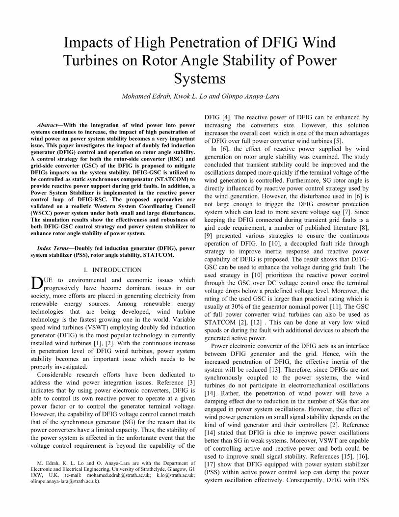
Abstract�With the integration of wind power into power
systems continues to increase, the impact of high penetration of
wind power on power system stability becomes a very important
issue. This paper investigates the impact of doubly fed induction
generator (DFIG) control and operation on rotor angle stability.
A control strategy for both the rotor-side converter (RSC) and
grid-side converter (GSC) of the DFIG is proposed to mitigate
DFIGs impacts on the system stability. DFIG-GSC is utilized to
be controlled as static synchronous compensator (STATCOM) to
provide reactive power support during grid faults. In addition, a
Power System Stabilizer is implemented in the reactive power
control loop of DFIG-RSC. The proposed approaches are
validated on a realistic Western System Coordinating Council
(WSCC) power system under both small and large disturbances.
The simulation results show the effectiveness and robustness of
both DFIG-GSC control strategy and power system stabilizer to
enhance rotor angle stability of power system.
Index Terms�Doubly fed induction generator (DFIG), power
system stabilizer (PSS), rotor angle stability, STATCOM.
I. INTRODUCTION
UE to environmental and economic issues which
progressively have become dominant issues in our
society, more efforts are placed in generating electricity from
renewable energy sources. Among renewable energy
technologies that are being developed, wind turbine
technology is the fastest growing one in the world. Variable
speed wind turbines (VSWT) employing doubly fed induction
generator (DFIG) is the most popular technology in currently
installed wind turbines [1], [2]. With the continuous increase
in penetration level of DFIG wind turbines, power system
stability becomes an important issue which needs to be
properly investigated.
Considerable research efforts have been dedicated to
address the wind power integration issues. Reference [3]
indicates that by using power electronic converters, DFIG is
able to control its own reactive power to operate at a given
power factor or to control the generator terminal voltage.
However, the capability of DFIG voltage control cannot match
that of the synchronous generator (SG) for the reason that its
power converters have a limited capacity. Thus, the stability of
the power system is affected in the unfortunate event that the
voltage control requirement is beyond the capability of the
M. Edrah, K. L. Lo and O. Anaya-Lara are with the Department of
Electronic and Electrical Engineering, University of Strathclyde, Glasgow, G1
1XW, U.K. (e-mail: [email protected]; [email protected];
DFIG [4]. The reactive power of DFIG can be enhanced by
increasing the converters size. However, this solution
increases the overall cost which is one of the main advantages
of DFIG over full power converter wind turbines [5].
In [6], the effect of reactive power supplied by wind
generation on rotor angle stability was examined. The study
concluded that transient stability could be improved and the
oscillations damped more quickly if the terminal voltage of the
wind generation is controlled. Furthermore, SG rotor angle is
directly influenced by reactive power control strategy used by
the wind generation. However, the disturbance used in [6] is
not large enough to trigger the DFIG crowbar protection
system which can lead to more severe voltage sag [7]. Since
keeping the DFIG connected during transient grid faults is a
gird code requirement, a number of published literature [8],
[9] presented various strategies to ensure the continuous
operation of DFIG. In [10], a decoupled fault ride through
strategy to improve inertia response and reactive power
capability of DFIG is proposed. The result shows that DFIG-
GSC can be used to enhance the voltage during grid fault. The
used strategy in [10] prioritizes the reactive power control
through the GSC over DC voltage control once the terminal
voltage drops below a predefined voltage level. Moreover, the
rating of the used GSC is larger than practical rating which is
usually at 30% of the generator nominal power [11]. The GSC
of full power converter wind turbines can also be used as
STATCOM [2], [12] . This can be done at very low wind
speeds or during the fault with additional devices to absorb the
generated active power.
Power electronic converter of the DFIG acts as an interface
between DFIG generator and the grid. Hence, with the
increased penetration of DFIG, the effective inertia of the
system will be reduced [13]. Therefore, since DFIGs are not
synchronously coupled to the power systems, the wind
turbines do not participate in electromechanical oscillations
[14]. Rather, the penetration of wind power will have a
damping effect due to reduction in the number of SGs that are
engaged in power system oscillations. However, the effect of
wind power generators on small signal stability depends on the
kind of wind generator and their controllers [2]. Reference
[14] stated that DFIG is able to improve power oscillations
better than SG in weak systems. Moreover, VSWT are capable
of controlling active and reactive power and both could be
used to improve small signal stability. References [15], [16],
[17] show that DFIG equipped with power system stabilizer
(PSS) within active power control loop can damp the power
system oscillation effectively. Consequently, DFIG with PSS
Impacts of High Penetration of DFIG Wind
Turbines on Rotor Angle Stability of Power
Systems Mohamed Edrah, Kwok L. Lo and Olimpo Anaya-Lara
D

can contribute to the oscillation damping much more
effectively than the SG with PSS control. The control schemes
used in [15], [17] are based on flux magnitude and angle
control (FMAC) whilst the common control schemes for the
commercial DFIG are based on standard decoupled d-q vector
control mechanism [18]. The use of active power modulation
can decrease the damping of the DFIG shaft mode [19]. This
increases the stress on the DFIG rotor shaft and decreases the
lifespan of the mechanical system. Moreover, reference [20]
reported that PSS with active power modulation is adversely
influenced by the torque variations due to tower shadow.
Additionally, the effectiveness of the PSS with active power
modulation can be reduced if the DFIG reactive power is used
to control the grid voltage [21]. Only a small number of papers
have been published concerning the use of DFIG reactive
power for oscillation damping [19], [22], [23]. Also none of
them take into account the influence of the crowbar system
when the control of active and reactive power is lost and a
large amount of reactive power is absorbed.
In this paper, a detailed analysis is carried out to study the
impacts of replacing conventional SGs with equivalent DFIG
wind farms on rotor angle stability of power systems. The
available DFIG reactive power is utilized by two control
strategies to lessen the impacts of DFIG on the rotor angle
stability of the existing synchronous generators. A cost
effective solution is to operate the existing DFIG-GSC as
reactive power source during grid faults. Moreover, to
overcome the effects of PSS power modulation, a PSS with
reactive power modulation taking into account the influence of
the crowbar system is designed in this paper. It is shown that
the proposed technique is an efficient and effective way to
improve the rotor angle stability by utilizing the available
DFIG reactive power. The benefits of such control scheme
could become more important as the levels of wind
penetration are increased.
The paper is structured as follows: Section II describes
the methodology used in this paper. Modelling and control of
DFIG is described in Section III. Section IV describes the test
system. The results and discussion of a number of scenarios
are outlined in Section V. Finally, the paper conclusions are
summarised in Section VI.
II. METHODOLOGY
In this section a methodology will be developed to study the
impact of DFIG on power system rotor angle stability and its
improvement.
To investigate the effect of grid connected DFIG on rotor
angle stability, one of the SGs is replaced by a wind farm
equipped with DFIG in the WSCC test power system. The
wind farm output rating is equivalent to the replaced SG, and
produces the same amount of power that is generated by the
replaced SG. The topology and operating conditions of the test
system with wind farm are the same prior to the SG
replacement. Moreover, to evaluate the system transient
response with high penetration of DFIG, the same fault is
applied to the test system as in synchronous generator case.
A. Small Signal Stability Analysis
The small signal stability problem usually occurs as a result
of inadequate damping of one of the system rotor oscillations.
The small signal stability analysis can detect system modes,
which are produced by electromechanical interactions between
power system SGs. Since, DFIG wind turbines are not
synchronously coupled to the power systems, the wind
turbines do not participate in electromechanical oscillations.
However, DFIG power electronics converters have the
potential to change electromechanical damping performance
[10]. The methodology of small signal stability is described in
the following steps:
1) Run small signal stability analysis in the frequency range
of 0.1 to 2 Hz.
2) Identify the main mode that has the lowest damping factor.
3) Determine the dominant machine with its main state
variables and their participation factor in the main mode.
4) Analyse the mode shape corresponding to the rotor speed
state to identify generators oscillating against each other.
5) Repeat the previous steps for different scenarios.
B. Transient Stability Analysis
To conduct a transient stability analysis, the system has to
be exposed to a large disturbance such as a three-phase short
circuit fault. The location of the disturbance has to be chosen
carefully for transient stability study. It may be selected
according to the result of small signal stability study. Modes
with low damping factor can be aggravated by a large
disturbance. Therefore, the fault has to be near the machine
that has the highest participation factor in the specified mode.
When the SGs electrical torque falls below mechanical
torque during fault, the rotor will accelerate leading to a higher
rotor angle position. However, for DFIG, the torque angle
characteristic does not exist due to its asynchronous operation.
Hence, the dynamic response of a DFIG to system
disturbances is different from that of a SG [24].
The rotor angle of the interconnected SGs will be used to
assess the stability of power system. Transient stability can be
measured by transient stability index (TSI) which is defined as
follows [25]:
max
max
360100 100 100
360
o
oWhere
ρη η
ρ−
−= × < <
+ (1)
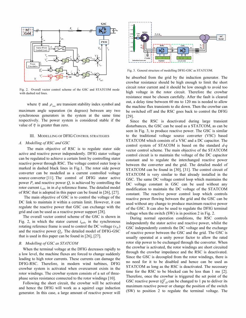
Fig. 1. Overall vector control scheme of the DFIG-RSC with voltage control
(dashed black lines) and power system stabiliser (dashed red lines).
where η and max
ρ are transient stability index symbol and
maximum angle separation (in degrees) between any two
synchronous generators in the system at the same time
respectively. The power system is considered stable if the
value of η is greater than zero.
III. MODELLING OF DFIG CONTROL STRATEGIES
A. Modelling of RSC and GSC
The main objective of RSC is to regulate stator side
active and reactive power independently. DFIG stator voltage
can be regulated to achieve a certain limit by controlling stator
reactive power through RSC. The voltage control outer loop is
marked in dashed black lines in Fig.1. The rotor side power
converter can be modelled as a current controlled voltage
source converter [11]. The control of DFIG stator active
power Ps and reactive power Qs is achieved by controlling the
rotor current irabc in in d-q reference frame. The detailed model
of RSC that is adopted in this paper can be found in [26], [27].
The main objective of GSC is to control the voltage of the
DC link to maintain it within a certain limit. However, it can
regulate the reactive power that GSC can exchange with the
grid and can be used as a reactive power support [28].
The overall vector control scheme of the GSC is shown in
Fig. 2, in which the stator current igabc in the synchronous
rotating reference frame is used to control the DC voltage (vdc)
and the reactive power Qg. The detailed model of DFIG-GSC
that is used in this paper can be found in [26], [27].
B. Modelling of GSC as STATCOM
When the terminal voltage at the DFIG decreases rapidly to
a low level, the machine fluxes are forced to change suddenly
leading to high rotor currents. These currents can damage the
DFIG-RSC. Therefore, in modern wind turbines, DFIG
crowbar system is activated when overcurrent exists in the
rotor windings. The crowbar system consists of a set of three-
phase series resistance connected to the rotor windings [10].
Following the short circuit, the crowbar will be activated
and hence the DFIG will work as a squirrel cage induction
generator. In this case, a large amount of reactive power will
be absorbed from the grid by the induction generator. The
crowbar resistance should be high enough to limit the short
circuit rotor current and it should be low enough to avoid too
high voltage in the rotor circuit. Therefore the crowbar
resistance must be chosen carefully. After the fault is cleared
out, a delay time between 60 ms to 120 ms is needed to allow
the machine flux transients to die down. Then the crowbar can
be switched off and the RSC goes back to control the DFIG
[29].
Since the RSC is deactivated during large transient
disturbances, the GSC can be used as a STATCOM, as can be
seen in Fig. 3, to produce reactive power. The GSC is similar
to the traditional voltage source converter (VSC) based
STATCOM which consists of a VSC and a DC capacitor. The
control system of STACOM is based on the standard d-q
vector control scheme. The main objective of the STATCOM
control circuit is to maintain the voltage of the DC capacitor
constant and to regulate the interchanged reactive power
between the converter and the grid. The detailed model of
STATCOM can be found in [30], [31]. The control circuit of
STATCOM is very similar to that already installed in the
GSC. The same DC voltage control loop which maintains the
DC voltage constant in GSC can be used without any
modification to maintain the DC voltage of the STATCOM
constant. The reactive power control loop which controls
reactive power flowing between the grid and the GSC can be
used without any change to produce maximum reactive power
of the GSC. It can also be used to regulate the DFIG terminal
voltage when the switch (SW) is in position 2 in Fig. 2.
During normal operation conditions, the RSC controls
independently the stator active and reactive power, whilst the
GSC independently controls the DC voltage and the exchange
of reactive power between the GSC and the grid. The GSC is
usually operated at a unity power factor to allow the rated
rotor slip power to be exchanged through the converter. When
the crowbar is activated, the rotor windings are short circuited
through the crowbar impedance and the RSC is deactivated.
Since the GSC is decoupled from the rotor windings, there is
no need for it to be disabled and hence can be used as
STATCOM as long as the RSC is deactivated. The necessary
time for the RSC to be blocked can be less than 1 ms [2].
Therefore, once the crowbar is triggered the set point of the
GSC reactive power (Q*g) can be changed to 1 pu to deliver its
maximum reactive power or change the position of the switch
(SW) to position 2 to regulate the terminal voltage. The
Fig. 2. Overall vector control scheme of the GSC and STATCOM mode
with dashed red lines.
Fig. 3. General structure of modelling DFIG-GSC as STATCOM.
reactive power that can be delivered from STATCOM mode is
limited by the rating of GSC which is about 30% of DFIG
rating. The synchronization of the RSC can be established
after the fault and during the crowbar active time. When the
crowbar is deactivated, the RSC is activated and the set point
of the GSC reactive power is set back to zero or change the
switch position back to 1 for normal operation condition.
C. Modelling of power system stabilizer
The aim of this section is to model a PSS for DFIG based
wind farm to enhance the test system stability and to damp
rotor angle oscillations. Designing a PSS for DFIG has to take
into account that the DFIG does not introduce any new
oscillation modes to the system. The main function of PSS is
to damp low frequency oscillations in the range of 0.1 to 2 Hz,
which are known as inter area or local modes. The input signal
of PSS can be any signal affected by the oscillation such as
machine speed, grid frequency, terminal voltage and
oscillating power. In this study, a local signal is carefully
chosen as PSS input signal to avoid the use of wide area
communications.
The location of the measurement point is very important for
the controller. The point of common coupling (PCC) of the
wind farm is a favourable selection point to avoid filtering
effect of transformers between the grid and the wind farm. The
best input signals reported in [32] are voltage and frequency.
Conversely other signals are less sensitive to system
oscillations and hence cannot provide adequate information
about oscillatory modes to be damped by the PSS. The
conventional PSS with lead-lag controllers is represented by
equation (2) [33].
31
2 4
1 1
1 1
1pss in
w
w
pss
ST STST
ST ST STKu u
++
+ + +=
(2)
where, uin and upss are control input and output signals
respectively, Kpss is the controller gain, Tw is a washout time
constant (s) and T1 to T4 are lead-lag time constants (s).
Since the DFIG is partly decoupled from the grid by the
partially rated converters, the power and rotational speed
signals are less sensitive to grid oscillations. Moreover, these
signals are influenced by torque variations due to tower
shadow. Therefore, the available local signals such as local
bus voltage and frequency are examined using residue
analysis. The residue of a particular mode can provide clear
measures of the mode�s sensitivity to the selected PSS input
signal. Based on the residue analysis, network frequency is
selected as best local signal for successfully damping
oscillations. The PSS output signal is added to the reference
voltage signal in the RSC as can be seen with the red dashed
lines in Fig. 1. The amount of damping is determined by the
PSS gain (Kpss). Washout block is a high pass filter that allows
a selected input frequency range and expected to act only
during transient period. The dynamic phase compensator can
provide a lead or lag phase in order to reduce rotor angle
oscillations. Limiter is used to prevent output signal from
exceeding control limits. The PSS output limit is set to ±0.1 pu
in this study. Parameters of the PSS are given in the following
equation.
5 1 0.06308 1 0.06308
1 5 1 0.26497 1 0.26497170
pss in
S S S
S S Su u
+ +=
+ + +
(3)
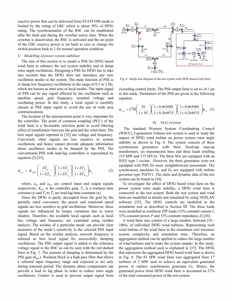
IV. TEST SYSTEM
The standard Western System Coordinating Council
(WSCC) 3-generators 9-buses test system is used to study the
impact of DFIG wind turbine on power system rotor angle
stability as shown in Fig. 4. The system consists of three
synchronous generators with three fixed-tap step-up
transformers, six transmission lines and three loads totalling
315 MW and 115 MVAr. The three SGs are equipped with an
IEEE type 1 exciter. However, the three generators were not
equipped with PSS for more straightforward assessment. The
synchronous machines G1 and G2 are equipped with turbine
governor type TGOV1. The static and dynamic data of the test
system can be found in [34].
To investigate the effect of DFIG based wind farm on the
power system rotor angle stability, a DFIG wind farm is
connected to the test system. Both the test system and wind
farm are modelled in details and simulated by using NEPLAN
software [35]. The DFIG controls are modelled in the
simulation tool as described in Section III. The three loads
were modelled as nonlinear ZIP loads (33% constant current I,
33% constant power P and 33% constant impedance Z) ]36[ .
A wind farm may consist of a large number, between (10 -
100s), of individual DFIG wind turbines. Representing each
wind turbine of the wind farm in the simulation tool increases
system complexity and simulation time. Therefore, an
aggregation method can be applied to reduce the large number
of wind turbines and to make the system simpler. In this study,
the aggregation method used is explained in [37]. The DFIG
that represents the aggregated DFIG based wind farm is shown
in Fig. 4. The 85 MW wind farm was aggregated from 17
turbines of 5 MW each to achieve an equivalent generated
power to replace synchronous generator G3. Hence, the
generated power from DFIG wind farm is accounted as 27%
of the total consumed power of the test system.
Fig. 4. Single line diagram of the test system with DFIG based wind farm.
V. RESULTS AND DISCUSSION
The simulation studies carried out in this section are based
on the methodology described in Section II. In this paper, five
different scenarios are analysed by small signal and transient
stability to show the impact of DFIG on power systems rotor
angle stability and how the disturbance can be mitigated by
the proposed control strategies. The description of each case is
as following:
• Scenario A: synchronous generator (SG) scenario. It is a
base case scenario in which the three generators are
conventional synchronous generators.
• Scenario B: fixed unity power factor (PF) control mode (no
reactive power injected to the system from DFIG). In this
scenario G3 is replaced by DFIG based wind farm with a PF
control mode.
• Scenario C: voltage control (VC) mode. The wind farm
operates to maintain its terminal voltage at 1pu. In this
scenario G3 is replaced by DFIG based wind farm with a
voltage control mode.
• Scenario D: STATCOM control mode. The proposed use of
DFIG-GSC as STATCOM control strategy will be
investigated in this scenario.
• Scenario E: DFIG power system stabilizer. The DFIG will
be equipped with the proposed PSS.
Scenarios A-C
A detailed small signal stability study on the test system
was conducted for the first three scenarios. The rotor angle
oscillations in the frequency range of 0.1 to 2 Hz are
monitored. The dominant electromechanical mode for each
scenario can be seen in Table I. The test system is stable and
the main modes of three scenarios are dominated by rotor
angle ȡ and speed Ȧ of generator G2. The frequency of each
mode is relatively similar in the three scenarios. The damping
factor of the main mode is improved from 3.5% (scenario A)
to 3.9% (scenario C). Moreover, contribution of G2 to the
oscillatory modes in DFIG scenarios is higher than the first
scenario.
For more detailed analysis, mode shape that corresponding
to the rotor speed state variable for the three scenarios is
examined. In first scenario, the results indicate that the three
synchronous generators of the test system are participating in
the mode, where G1 is oscillating against the other two. But
when G3 is replaced by DFIG, the wind farm does not
contribute to the mode. The mode gets the contribution from
G1 and G2 which are oscillating against each other.
The result of small signal stability study shows G2 has the
highest participation factor. Therefore, according to the
methodology described in Section II, the location of the
disturbance has to be near G2. A disturbance lasting 9-sycle
(150 ms) of a 3-phase to ground fault at 60 Hz was imposed
near Bus 7 on line 5-7. The fault was cleared by opening both
sides of the faulted line simultaneously.
In order to assess the effect of DFIG based wind farm on
transit stability of the test system, rotor angle of each
generator is observed, from which the transient stability index
is calculated. Active and reactive power output of each
generator is monitored. Moreover, terminal voltage of the
replaced synchronous generator (Bus 3) is monitored. The
angle of the largest synchronous generator G1, which is the
slack generator, was taken as a reference angle.
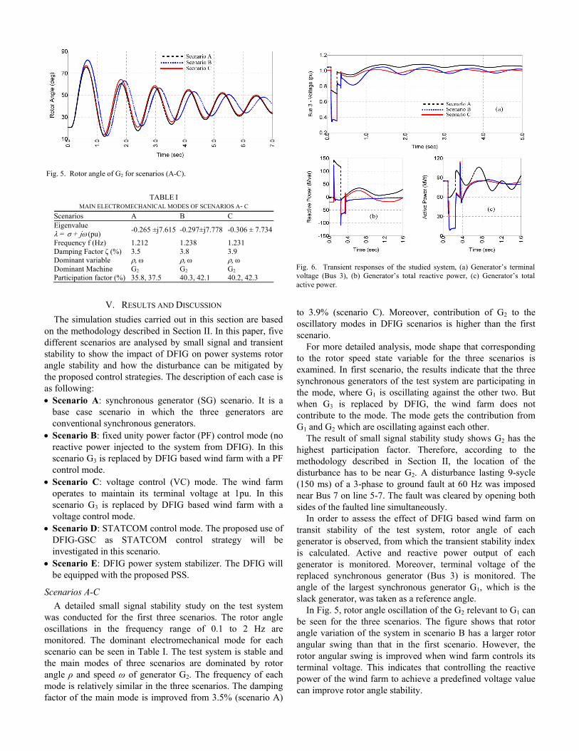
In Fig. 5, rotor angle oscillation of the G2 relevant to G1 can
be seen for the three scenarios. The figure shows that rotor
angle variation of the system in scenario B has a larger rotor
angular swing than that in the first scenario. However, the
rotor angular swing is improved when wind farm controls its
terminal voltage. This indicates that controlling the reactive
power of the wind farm to achieve a predefined voltage value
can improve rotor angle stability.
Fig. 6. Transient responses of the studied system, (a) Generator�s terminal
voltage (Bus 3), (b) Generator�s total reactive power, (c) Generator�s total
active power.
Fig. 5. Rotor angle of G2 for scenarios (A-C).
TABLE I
MAIN ELECTROMECHANICAL MODES OF SCENARIOS A- C
Scenarios A B C
Eigenvalue
そ = j + jの (pu) -0.265 ±j7.615 -0.297±j7.778 -0.306 ± 7.734
Frequency f (Hz) 1.212 1.238 1.231
Damping Factor こ (%) 3.5 3.8 3.9
Dominant variable と, の と, の と, の
Dominant Machine G2 G2 G2
Participation factor (%) 35.8, 37.5 40.3, 42.1 40.2, 42.3

Fig. 7. Reactive power of DFIG-GSC during normal operation (dotted green
line) and STATCOM modes (red line).
Fig. 8. (a) DFIG terminal voltage and (b) DFIG reactive power with and
without STATCOM mode.
Fig. 9. Rotor angle of G2 for scenario D.
Table II shows that the stability of the test system is reduced
after synchronous generator G3 is replaced by a wind farm
operating at a unity power factor. However, DFIG with
voltage control mode improves G2 rotor angle.
Terminal voltage of G3 falls to about 0.7 pu during the fault
period and then recovered quickly to its normal value after the
fault is cleared as indicated in Fig. 6(a). However, in the case
of wind farm, the terminal voltage falls to 0.4 pu during the
fault period and then recovers to about 0.8 pu after fault
clearance when the crowbar is still active. During the active
crowbar time the induction generator absorbs a large amount
of reactive power as can be seen in Fig. 6(b). In comparison to
the scenario B, the terminal voltage of wind farm in scenario
C recovers more quickly to its predefined value after the
crowbar is deactivated. This is due to the reactive power that
is injected into the grid to maintain the terminal voltage of the
wind farm at its nominal value. Moreover, there is more
reactive power injected into the grid in the SG case than that is
injected by the wind farm. This is due to the ability of the SG
to inject reactive power over the whole fault period.
Active power of G3 and DFIG based wind farm for each
scenario can be seen in Fig. 6(c). The active power produced
by DFIG in voltage control scenario is similar to the unity
power factor scenario. However, the active power of wind
farm scenarios and SG scenario are different during and after
the fault is cleared. Synchronous generator G3 is providing the
grid with about 60 MW of active power during the fault period
compared to just 12 MW injected from the wind farm. The
active power of G3 after the fault oscillates because of its rotor
inertia response. But in the case of wind farm, the active
power output after the fault is relatively smooth.
The analysis and simulation results of previous scenarios
clearly show that replacing synchronous generator with DFIG
based wind farm has no negative impacts on small signal
stability of power systems. However, the impacts on transient
stability of the system would depend on the control strategy
used within the DFIG-RSC. The results of completed analysis
demonstrate that although DFIG with voltage control can
produce reactive power after crowbar deactivation time, both
of control modes (PF and VC) cannot provide any reactive
power during crowbar active time. On the contrary, DFIG
absorbs a large amount of reactive power leading to a severe
voltage drop. In the next scenario, STATCOM control mode
will be used within the DFIG-GSC to supply some of the
reactive power absorbed by the induction generator during
disturbances and hence improves wind farm terminal voltage.
Scenario D: STATCOM control mode
Fig. 7 shows the amount of reactive power that can be
delivered from DFIG-GSC during normal operation and
STATCOM mode. In the case of normal operation, GSC
cannot provide any reactive power support during fault. In this
case the GSC has no contribution towards transient stability
improvement. However, in the case of STATCOM mode,
GSC provides reactive power support during and after the
fault when the DFIG crowbar is still active. The same 3-phase
short-circuit fault as stated in previous scenarios is applied at
(t1 = 0.1 s). The DFIG crowbar is triggered at (t2 = 0.12 s) to
initiate the STATCOM mode after few milliseconds. During
the fault period, the DFIG-GSC provides about 20 MVAr
which helps to improve the terminal voltage of DFIG wind
farm. The wind farm terminal voltage is improved from 0.37
pu to 0.42 pu with STATCOM mode during the fault as shown
in Fig. 8(a). Although, the fault is cleared at (t3 = 0.25 s), the
STATCOM mode is deactivated at (t4 = 0.35 s) when the
DFIG crowbar system is also deactivated. After the fault,
DFIG-GSC provides its full rated reactive power to support
the terminal voltage of wind farm. The terminal voltage of the
wind farm recovers from 0.81 pu to 0.88 pu with STATCOM
mode. Fig. 8(b) clearly shows that with STATCOM mode less
reactive power is absorbed from the grid.
TABLE II
TRANSIENT STABILITY INDEX OF SCENARIOS A-C
TSI Scenario A Scenario B Scenario C
65.3 62.87 64.77
TABLE III
TRANSIENT STABILITY INDEX OF SCENARIO D
TSI PF VC
63.55 65.38

Fig. 9 presents the rotor angle of G2 when STATCOM
mode is used. The magnitude of the rotor angles in scenarios
B&C is slightly lower when it is compared to those in Fig. 5.
A smaller rotor angle deviation of G2 has been gained in the
case of STATCOM mode. The rotor angle magnitude and
oscillation in the case of DFIG voltage control mode with
STATCOM mode performs as good as if not better when
compared to synchronous generator scenario. Therefore,
replacing a SG by DFIG based wind farm controlling its
terminal voltage and equipped with STATCOM mode has no
negative impacts on the transient stability of the power
system. Moreover, this result is also reinforced by the transient
stability index as shown in Table III. Once again, the stability
index of scenarios B&C is improved from 62.87 and 64.77
(Table II) to 63.55 and 65.38 (Table III) respectively. It should
be noticed that the VC mode with STATCOM mode has better
stability index (65.38) than the SG case (65.3).
The results of this scenario indicate that transient stability of
the system is improved by using DFIG-GSC as STATCOM.
The reactive power provided by STATCOM mode improves
the terminal voltage of wind farm during the disturbance and
hence resulting in better system stability. Since the terminal
voltage of DFIG based wind farm can be controlled by the
voltage control strategy of RSC during normal operation
conditions, the STATCOM mode can provide a voltage
support during transient periods when the crowbar is active.
Scenario E: DFIG power system stabilizer
In this scenario, the proposed model of power system
stabilizer in Section III is examined. The PSS is attached to a
DFIG based wind farm with both voltage control strategy and
STATCOM mode. As can be seen in Table IV, once again, the
main modes of three scenarios are dominated by rotor angle と and speed の of generator G2. However, the system is much
more stable in this scenario than all previous scenarios. Rotor
angle stability of the system is improved due to the
effectiveness of the proposed PSS. The damping factor of the
main mode is increased significantly from 3.9% (without PSS)
to 12% (with PSS).
Dynamic response of rotor angle of G2 with and without
PSS is shown in Fig. 10. The time domain simulation clearly
shows the oscillation damps quickly and the rotor angle steady
state value is reached in a time of less than 4 s. Therefore, it is
clear that DFIG based wind farm has the capability to improve
rotor angle oscillations.
Since PSS output signal is connected to the reactive power
loop, the difference between the two cases (with and without
PSS) is only in the reactive power output as can be seen in
Fig. 11. This is apparent only after the fault is cleared and
when the PSS is activated to damp the rotor angle oscillations.
After the fault is cleared the terminal voltage of the wind farm
with PSS is more variable, as shown in Fig. 11(a), due to the
reactive power variation. However, this variation is limited
and is effectively damped in 4 s.
DFIG based wind farms equipped with PSS can use
STATCOM mode to improve system transient stability. In a
similar way to scenario D, the GSC can be used as a reactive
power support during the time when DFIG crowbar is active.
Fig. 11(c) shows the reactive power output of the STATCOM
mode when the wind farm is equipped with PSS. The GSC
provides a reactive power support during the time when DFIG
crowbar is active. Conversely, the PSS starts to control the
DFIG stator reactive power after the crowbar is deactivated.
Based on the results of this scenario, DFIG based wind
farms can damp rotor angle oscillation effectively by using a
PSS attached to the DFIG-RSC reactive power control loop.
Moreover, the transient stability results indicate that the
DFIG-GSC control strategy can be used on the same DFIG
based wind farm that is fitted with PSS to improve transient
stability of the power system.
Fig. 11. (a) DFIG terminal voltage, (b) DFIG active power, (c) DFIG stator
and GSC reactive power.
Fig. 10. Rotor angle of G2 for scenario (E).
TABLE IV
MAIN ELECTROMECHANICAL MODE OF SCENARIO E
Scenarios E
Eigenvalue
そ = j + jの (pu) -0.967 ± 7.964
Frequency f (Hz) 1.268
Damping Factor こ (%) 12
Dominant variable と, の
Dominant Machine G2
Participation factor (%) 48.3, 50.8
VI. CONCLUSIONS
In this paper, the impact of high penetration of DFIG
based wind farm on rotor angle stability has been investigated.
From the results of this study, it is clear that replacing
conventional SGs with equivalent DFIG wind farms have
negative impacts on rotor angle stability of power systems.
However, theses impacts can be mitigated by the proposed
control strategies and hence the penetration of wind power can
be increased without degrading the rotor angle stability. The
use of GSC as STATCOM is a cost effective solution to
support local voltage of wind farms without an external
STATCOM. Moreover, the implementation of the proposed
PSS within the reactive power control loop of the wind farm
can influence the rotor angle of SG and thus damp the power
system oscillations effectively. As the levels of wind
penetration are increased, the benefit of such control scheme is
that the DFIG based wind farms are able to take over the SGs
responsibility to support power system stability.
REFERENCES
[1] F. Blaabjerg and M. Ke, "Future on Power Electronics for Wind Turbine
Systems," Emerging and Selected Topics in Power Electronics, IEEE
Journal of, vol. 1, pp. 139-152, 2013.
[2] T. Ackermann, Wind Power in Power Systems: John Wiley & Sons,
2012.
[3] W. Feng, Z. Xiao-Ping, K. Godfrey, and J. Ping, "Modeling and Control
of Wind Turbine with Doubly Fed Induction Generator," in Power
Systems Conference and Exposition, 2006. PSCE '06. 2006 IEEE PES,
2006, pp. 1404-1409.
[4] M. J. Hossain, H. R. Pota, M. A. Mahmud, and R. A. Ramos,
"Investigation of the Impacts of Large-Scale Wind Power Penetration on
the Angle and Voltage Stability of Power Systems," Systems Journal,
IEEE, vol. 6, pp. 76-84, 2012.
[5] R. Cardenas, R. Pena, S. Alepuz, and G. Asher, "Overview of control
systems for the operation of DFIGs in wind energy applications," IEEE
Transactions on Industrial Electronics, vol. 60, pp. 2776-2798, 2013.
[6] E. Vittal, M. O'Malley, and A. Keane, "Rotor Angle Stability With High
Penetrations of Wind Generation," Power Systems, IEEE Transactions
on, vol. 27, pp. 353-362, 2012.
[7] G. Pannell, D. J. Atkinson, and B. Zahawi, "Minimum-threshold
crowbar for a fault-ride-through grid-code-compliant DFIG wind
turbine," Energy Conversion, IEEE Transactions on, vol. 25, pp. 750-
759, 2010.
[8] A. H. Kasem, E. F. El-Saadany, H. H. El-Tamaly, and M. A. A. Wahab,
"An improved fault ride-through strategy for doubly fed induction
generator-based wind turbines," Renewable Power Generation, IET, vol.
2, pp. 201-214, 2008.
[9] A. D. Hansen and G. Michalke, "Fault ride-through capability of DFIG
wind turbines," Renewable Energy, vol. 32, pp. 1594-1610, 2007.
[10] L. G. Meegahapola, T. Littler, and D. Flynn, "Decoupled-DFIG Fault
Ride-Through Strategy for Enhanced Stability Performance During Grid
Faults," Sustainable Energy, IEEE Transactions on, vol. 1, pp. 152-162,
2010.
[11] R. Pena, J. Clare, and G. Asher, "Doubly fed induction generator using
back-to-back PWM converters and its application to variable-speed
wind-energy generation," IEE Proceedings-Electric Power Applications,
vol. 143, pp. 231-241, 1996.
[12] T. H. Nguyen and D.-C. Lee, "Advanced fault ride-through technique
for PMSG wind turbine systems using line-side converter as
STATCOM," Industrial Electronics, IEEE Transactions on, vol. 60, pp.
2842-2850, 2013.
[13] J. G. Slootweg and W. L. Kling, "The impact of large scale wind power
generation on power system oscillations," Electric Power Systems
Research, vol. 67, pp. 9-20, 2003.
[14] G. Tsourakis, B. M. Nomikos, and C. D. Vournas, "Contribution of
Doubly Fed Wind Generators to Oscillation Damping," Energy
Conversion, IEEE Transactions on, vol. 24, pp. 783-791, 2009.
[15] Y. Mishra, S. Mishra, M. Tripathy, N. Senroy, and Z. Y. Dong,
"Improving Stability of a DFIG-Based Wind Power System With Tuned
Damping Controller," Energy Conversion, IEEE Transactions on, vol.
24, pp. 650-660, 2009.
[16] M. Zhixin, F. Lingling, D. Osborn, and S. Yuvarajan, "Control of DFIG-
Based Wind Generation to Improve Interarea Oscillation Damping,"
Energy Conversion, IEEE Transactions on, vol. 24, pp. 415-422, 2009.
[17] F. M. Hughes, O. Anaya-Lara, N. Jenkins, and G. Strbac, "A power
system stabilizer for DFIG-based wind generation," Power Systems,
IEEE Transactions on, vol. 21, pp. 763-772, 2006.
[18] S. Muller, M. Deicke, and R. W. De Doncker, "Doubly fed induction
generator systems for wind turbines," Industry Applications Magazine,
IEEE, vol. 8, pp. 26-33, 2002.
[19] F. Lingling, Y. Haiping, and M. Zhixin, "On Active/Reactive Power
Modulation of DFIG-Based Wind Generation for Interarea Oscillation
Damping," Energy Conversion, IEEE Transactions on, vol. 26, pp. 513-
521, 2011.
[20] F. M. Hughes, O. Anaya-Lara, G. Ramtharan, N. Jenkins, and G. Strbac,
"Influence of Tower Shadow and Wind Turbulence on the Performance
of Power System Stabilizers for DFIG-Based Wind Farms," Energy
Conversion, IEEE Transactions on, vol. 23, pp. 519-528, 2008.
[21] M. Edrah, K. L. Lo, A. Elansari, and O. Anaya-Lara, "Power oscillation
damping capabilities of doubly fed wind generators," in Power
Engineering Conference (UPEC), 2014 49th International Universities,
2014, pp. 1-6.
[22] Y. Haiping, F. Lingling, and M. Zhixin, "Reactive power modulation for
inter-area oscillation damping of DFIG-based wind generation," in
Power and Energy Society General Meeting, 2010 IEEE, 2010, pp. 1-9.
[23] R. D. Fernandez, R. J. Mantz, and P. E. Battaiotto, "Contribution of
wind farms to the network stability," in Power Engineering Society
General Meeting, 2006. IEEE, 2006, p. 6 pp.
[24] F. M. Hughes, O. Anaya-Lara, N. Jenkins, and G. Strbac, "Control of
DFIG-based wind generation for power network support," Power
Systems, IEEE Transactions on, vol. 20, pp. 1958-1966, 2005.
[25] L. Shi, S. Dai, Y. Ni, L. Yao, and M. Bazargan, "Transient stability of
power systems with high penetration of DFIG based wind farms," in
Power & Energy Society General Meeting, 2009. PES'09. IEEE, 2009,
pp. 1-6.
[26] Q. Wei, G. K. Venayagamoorthy, and R. G. Harley, "Real-Time
Implementation of a STATCOM on a Wind Farm Equipped With
Doubly Fed Induction Generators," Industry Applications, IEEE
Transactions on, vol. 45, pp. 98-107, 2009.
[27] L. Qu and W. Qiao, "Constant power control of DFIG wind turbines
with supercapacitor energy storage," Industry Applications, IEEE
Transactions on, vol. 47, pp. 359-367, 2011.
[28] E. Tremblay, A. Chandra, and P. Lagace, "Grid-side converter control of
DFIG wind turbines to enhance power quality of distribution network,"
in Power Engineering Society General Meeting, 2006. IEEE, 2006, p. 6
pp.
[29] I. Erlich, H. Wrede, and C. Feltes, "Dynamic Behavior of DFIG-Based
Wind Turbines during Grid Faults," in Power Conversion Conference -
Nagoya, 2007. PCC '07, 2007, pp. 1195-1200.
[30] P. Rao, M. L. Crow, and Y. Zhiping, "STATCOM control for power
system voltage control applications," Power Delivery, IEEE
Transactions on, vol. 15, pp. 1311-1317, 2000.
[31] S. Li, L. Xu, and T. A. Haskew, "Control of VSC-based STATCOM
using conventional and direct-current vector control strategies,"
International Journal of Electrical Power & Energy Systems, vol. 45,
pp. 175-186, 2013.
[32] A. Mendonca and J. A. P. Lopes, "Robust tuning of power system
stabilisers to install in wind energy conversion systems," Renewable
Power Generation, IET, vol. 3, pp. 465-475, 2009.
[33] M. A. Abido, "A novel approach to conventional power system
stabilizer design using tabu search," International Journal of Electrical
Power & Energy Systems, vol. 21, pp. 443-454, 1999.
[34] P. M. Anderson and A. A. Fouad, POWER SYSTEM CONTROL AND
STABILITY: Wiley-IEEE Press 2003.
[35] B. Busarello. Cott+ Partner AG,�NEPLAN, power system analysis,�
Available: www. neplan. ch
[36] "Standard load models for power flow and dynamic performance
simulation," Power Systems, IEEE Transactions on, vol. 10, pp. 1302-
1313, 1995.
[37] M. Pろller and S. Achilles, "Aggregated wind park models for analyzing
power system dynamics," 2003.