Embed Size (px)
Citation preview

8/4/2019 Dfig Intro
http://slidepdf.com/reader/full/dfig-intro 1/20
14
Introduction to Doubly-Fed Induction Generator for Wind Power Applications
Dr John Fletcher and Jin YangUniversity of Strathclyde, Glasgow
United Kingdom
1. Introduction
This chapter introduces the operation and control of a Doubly-fed Induction Generator(DFIG) system. The DFIG is currently the system of choice for multi-MW wind turbines.The aerodynamic system must be capable of operating over a wide wind speed range inorder to achieve optimum aerodynamic efficiency by tracking the optimum tip-speed ratio.Therefore, the generator’s rotor must be able to operate at a variable rotational speed. TheDFIG system therefore operates in both sub- and super-synchronous modes with a rotorspeed range around the synchronous speed. The stator circuit is directly connected to thegrid while the rotor winding is connected via slip-rings to a three-phase converter. Forvariable-speed systems where the speed range requirements are small, for example ±30% ofsynchronous speed, the DFIG offers adequate performance and is sufficient for the speed
range required to exploit typical wind resources.An AC-DC-AC converter is included in the induction generator rotor circuit. The powerelectronic converters need only be rated to handle a fraction of the total power – the rotorpower – typically about 30% nominal generator power. Therefore, the losses in the powerelectronic converter can be reduced, compared to a system where the converter has tohandle the entire power, and the system cost is lower due to the partially-rated powerelectronics. This chapter will introduce the basic features and normal operation of DFIGsystems for wind power applications basing the description on the standard inductiongenerator. Different aspects that will be described include their variable-speed feature,power converters and their associated control systems, and application issues.
2. Steady-state operation of the Doubly-Fed Induction Generator (DFIG)
The DFIG is an induction machine with a wound rotor where the rotor and stator are bothconnected to electrical sources, hence the term ‘doubly-fed’. The rotor has three phasewindings which are energised with three-phase currents. These rotor currents establish therotor magnetic field. The rotor magnetic field interacts with the stator magnetic field todevelop torque. The magnitude of the torque depends on the strength of the two fields (thestator field and the rotor field) and the angular displacement between the two fields.Mathematically, the torque is the vector product of the stator and rotor fields. Conceptually,the torque is developed by magnetic attraction between magnet poles of opposite polaritywhere, in this case, each of the rotor and stator magnetic fields establish a pair of magnet
8/4/2019 Dfig Intro
http://slidepdf.com/reader/full/dfig-intro 2/20
Paths to Sustainable Energy260
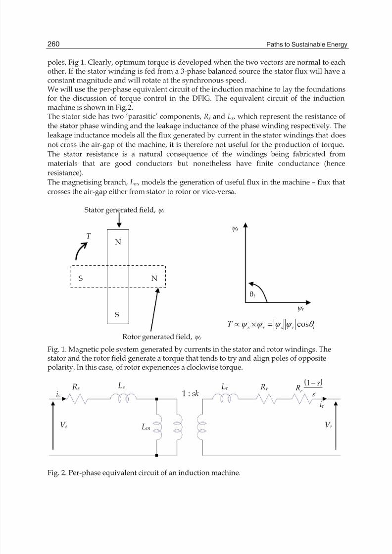
poles, Fig 1. Clearly, optimum torque is developed when the two vectors are normal to eachother. If the stator winding is fed from a 3-phase balanced source the stator flux will have aconstant magnitude and will rotate at the synchronous speed.We will use the per-phase equivalent circuit of the induction machine to lay the foundations
for the discussion of torque control in the DFIG. The equivalent circuit of the inductionmachine is shown in Fig.2.The stator side has two ‘parasitic’ components, Rs and Ls, which represent the resistance of
the stator phase winding and the leakage inductance of the phase winding respectively. The
leakage inductance models all the flux generated by current in the stator windings that does
not cross the air-gap of the machine, it is therefore not useful for the production of torque.
The stator resistance is a natural consequence of the windings being fabricated from
materials that are good conductors but nonetheless have finite conductance (hence
resistance).
The magnetising branch, Lm, models the generation of useful flux in the machine – flux that
crosses the air-gap either from stator to rotor or vice-versa.
N
S
NS
Stator generated field, \ s
Rotor generated field, \ r
\ s
\ r
t r sr sT T \ \ \ \ cosuv
t
T
Fig. 1. Magnetic pole system generated by currents in the stator and rotor windings. Thestator and the rotor field generate a torque that tends to try and align poles of oppositepolarity. In this case, of rotor experiences a clockwise torque.
Rs s
s Rr
1
Rr Ls
Lm
Lr 1 : sk
V s V r
ir
is
Fig. 2. Per-phase equivalent circuit of an induction machine.
8/4/2019 Dfig Intro
http://slidepdf.com/reader/full/dfig-intro 3/20
Introduction to Doubly-Fed Induction Generator for Wind Power Applications 261
Like the stator circuit, the rotor circuit also has two parasitic elements. The rotor leakagereactance, Lr , and the rotor resistance Rr . In addition, the rotor circuit models the generatedmechanical power by including an additional rotor resistance component, Rr (1–s)/s. Notethat the rotor and stator circuits are linked via a transformer whose turns ratio depends on
the actual turns ratio between the stator and rotor (1:k), and also the slip, s, of the machine.In an induction machine the slip is defined as
s r
s
n ns
n
(1)
where ns and nr are the synchronous speed and the mechanical speed of the rotorrespectively. The synchronous speed is given by
60 es
f n
p rpm (2)
where p = number of pole pairs and f e is the electrical frequency of the applied stator voltage.We will first consider the operation of the machine as a standard induction motor. If therotor circuit is left open circuit and the rotor locked (standstill), when stator excitation isapplied, a voltage will be generated at the output terminals of the rotor circuit, V r . Thefrequency of this output will be at the applied stator frequency as slip in this case is 1. If therotor is turned progressively faster and faster in the sub-synchronous mode, the frequencyat the output terminals of the rotor will decrease as the rotor accelerates towards thesynchronous speed. At synchronous speed the rotor frequency will be zero. As the rotoraccelerates beyond synchronous speed (the super-synchronous mode) the frequency of therotor voltage begins to increase again, but has the opposite phase sequence to the sub-
synchronous mode. Hence, the frequency of the rotor voltage is
r e f sf (3)
No rotor currents can flow with the rotor open circuit, hence there is no torque production
as there is no rotor field \ r , Fig 1. If the rotor was short circuited externally, rotor currentscan flow, and they will flow at the frequency given by (3). The rotor currents produce a rotor
magnetic field, \ r , which rotates at the same mechanical speed as the stator field, \ s. Thetwo fields interact to produce torque, Fig. 1.It is important to recognise that the rotor magnetic field and the stator magnetic field bothrotate at the synchronous speed. The rotor may be turning asynchronously, but the rotor
field rotates at the same speed as the stator field.The mechanical torque generated by the machine is found by calculating the powerabsorbed (or generated) by the rotor resistance component Rr (1–s)/s. This is shown to be
2 13mech r r
sP i R
s
§ · ¨ ¸
© ¹(4)
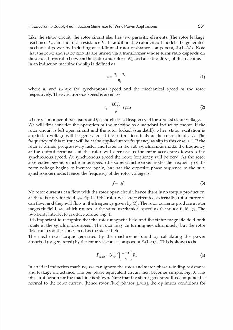
In an ideal induction machine, we can ignore the rotor and stator phase winding resistanceand leakage inductance. The per-phase equivalent circuit then becomes simple, Fig. 3. Thephasor diagram for the machine is shown. Note that the stator generated flux component isnormal to the rotor current (hence rotor flux) phasor giving the optimum conditions for
8/4/2019 Dfig Intro
http://slidepdf.com/reader/full/dfig-intro 4/20
Paths to Sustainable Energy262
Lm
i’r is
s
s R r
1'V s
im
\ m , im
\ r , i r
V s
Fig. 3. Simplified equivalent circuit of the induction machine assuming low values of slipand negligible stator and rotor leakage reactance. Phasor diagram demonstrates optimalorientation of magnetising current and rotor current.torque production (note this is true for low values of slip only). Using this simplified circuitdiagram, the mechanical torque production is then:
'2' 13 r
mech r m
RsT i
s Z
§ · ¨ ¸
© ¹(5)
As 1 m
m
s
p
Z Z
and
' 'r r s
m m ms s
i RV L i
s\
Z Z (6)
Then
' ''2' ' '13 3 3
r r r mech r r m r
m s
i RRsT i p i p i
s s
\
Z Z
§ · ¨ ¸
© ¹
(7)
The key point in this development is to show that the developed torque is controlled by the
combination of the stator generated flux, \ m, and the rotor current magnitude, ir ’, if the twovectors are maintained in quadrature, Fig. 1. In the DFIG system, torque is controlled bycalculating the physical position and magnitude of the stator generated flux (by monitoringthe position and magnitude of the applied stator voltage which in this case is imposed by thegrid voltage magnitude, frequency and phase) and regulating the rotor currents such that theyare normal to the stator flux with a magnitude that will generate the desired torque.The DFIG system therefore has to control the magnitude, frequency and phase of the appliedrotor current. Most DFIG systems utilise closed-loop current control using a voltage-source
inverter (VSI). At this stage, the voltage source inverter can be viewed as a three-phase voltagesource whose magnitude and phase can be altered instantaneously – this will be illustrated inSection 2. Therefore, the VSI can be used to regulate the rotor current. In order to properlyposition the rotor current knowledge of the physical position of the rotor is required using amechanical position sensor, for example. In such a way, the rotor current (hence flux) can beoriented optimally with respect to the stator flux to generate the desired torque.
3. Rotor power converters
This section will detail the AC-DC-AC converter used on the rotor which consists of twovoltage-sourced converters, i.e., rotor-side converter (RSC) and grid-side converter (GSC),
8/4/2019 Dfig Intro
http://slidepdf.com/reader/full/dfig-intro 5/20
Introduction to Doubly-Fed Induction Generator for Wind Power Applications 263
which are connected “back-to-back.” Between the two converters a dc-link capacitor isplaced, as energy storage, in order to keep the voltage variations (or ripple) in the dc-linkvoltage small. With the rotor-side converter it is possible to control the torque or the speedof the DFIG and also the power factor at the stator terminals, while the main objective for
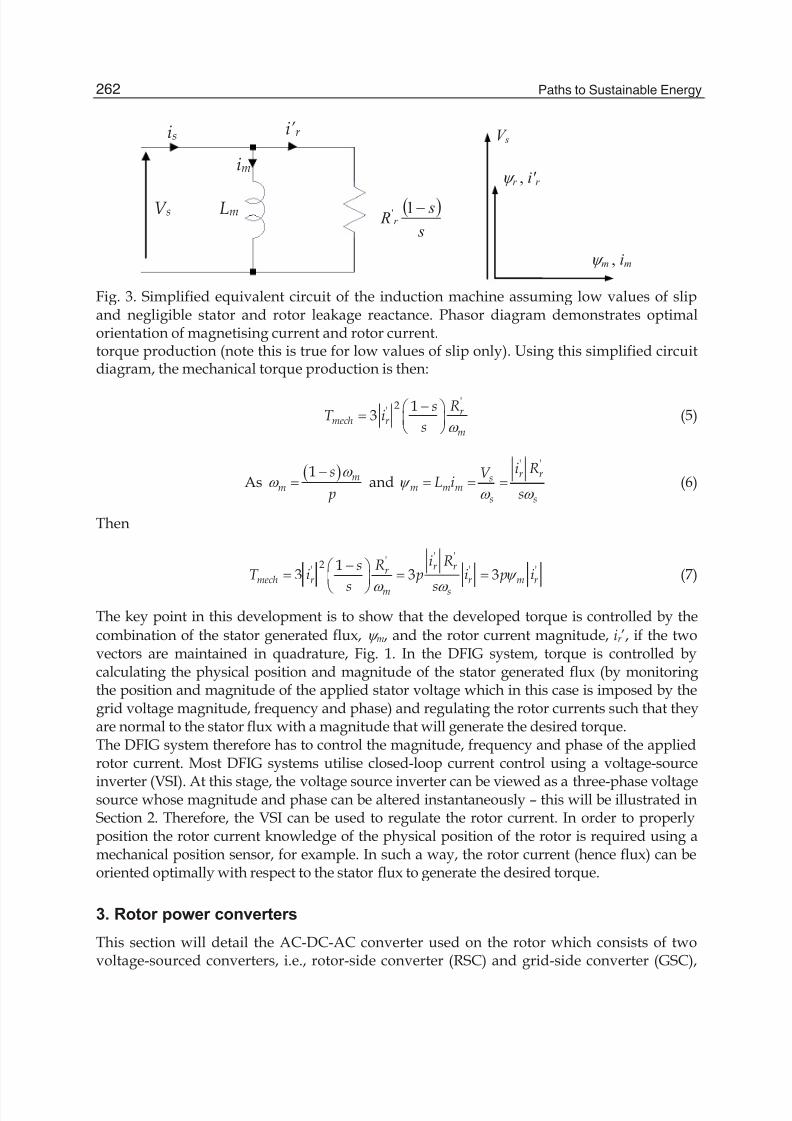
the grid-side converter is to keep the dc-link voltage constant regardless of the magnitudeand direction of the rotor power. The grid-side converter works at the grid frequency(leading or lagging in order to generate or absorb a controllable magnitude of reactivepower). A transformer may be connected between the grid-side inverter or the stator, andthe grid. The rotor-side converter works at different frequencies, depending on the windspeed.The back-to-back arrangement of the converters provides a mechanism of converting thevariable voltage, variable frequency output of the generator (as its speed changes) into afixed frequency, fixed voltage output compliant with the grid. The DC link capacitance is anenergy storage element that provides the energy buffer required between the generator andthe grid.
The back-to-back inverter-converter arrangement
IG
T
GB – GearboxIG – Induction Generator
RSC – Rotor-Side Converter GSC – Grid Side Converter T – Transformer
RSC GSC
GB
Fig. 4. Typical back-to-back arrangement of inverter and converter circuits to control powerflow.
At the current state of development, most DFIG power electronics utilise a two-level six-switch converter, Fig. 4. Two-level refers to the number of voltage levels that can beproduced at the output of each bridge leg of the converter. A two-level converter can
typically output zero volts or V dc, where V dc is the voltage of the dc link. Fig. 4 shows twosuch converters connected in a back-to-back arrangement with a DC link between the twoconverters. The switching elements in higher power converters are likely to be Insulated-gate Bipolar Transistors (IGBTs). The six-switch converter can synthesise a three-phaseoutput voltage which can be of arbitrary magnitude, frequency and phase, within theconstraint that the peak line voltage is less than the DC link voltage. The converter iscapable of changing the output voltage almost instantaneously – the limit is related to theswitching frequency of the pulse-width modulated switching devices, and delaysintroduced by any filtering on the output (typical on the grid-side converter). The converterswitches are switched ON and OFF with a fixed frequency but with a pulse-width that isvaried in order to control the output voltage.
8/4/2019 Dfig Intro
http://slidepdf.com/reader/full/dfig-intro 6/20
Paths to Sustainable Energy264
The voltage source inverter
V ab V bc
V ca
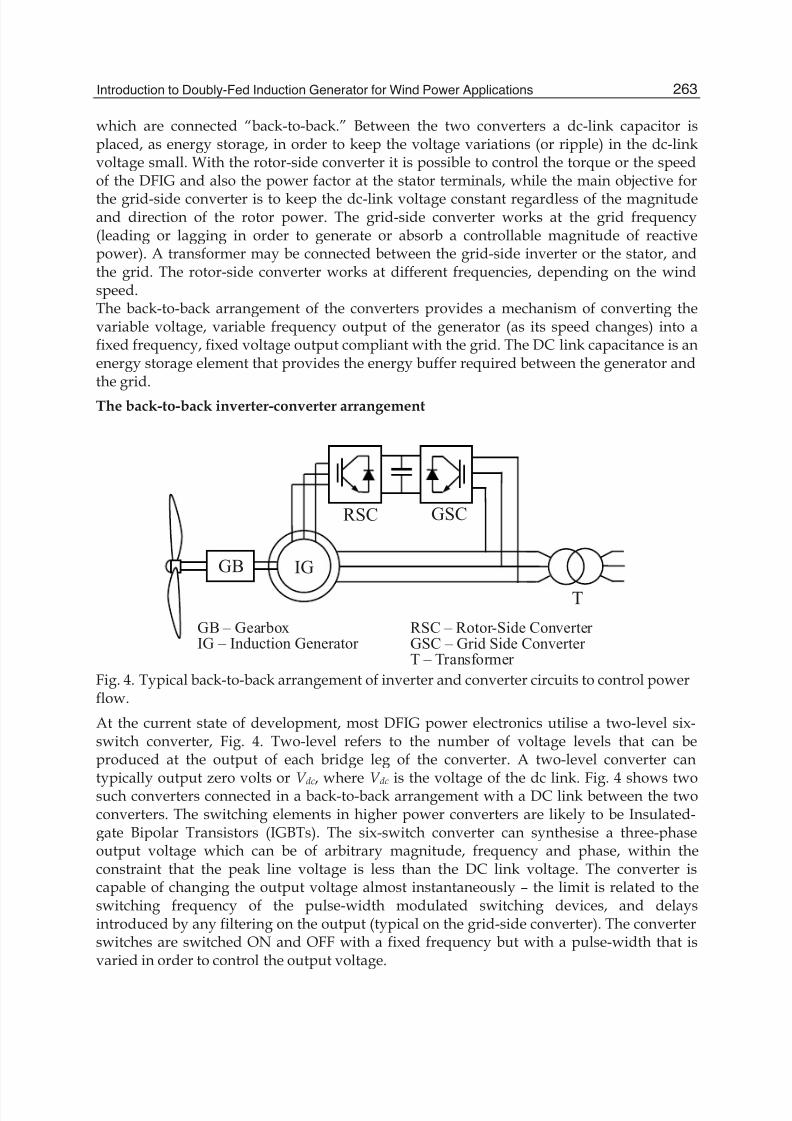
Fig. 5. Six-switch voltage source inverter circuit.
Fig. 6. One bridge leg of a voltage source inverter circuit.
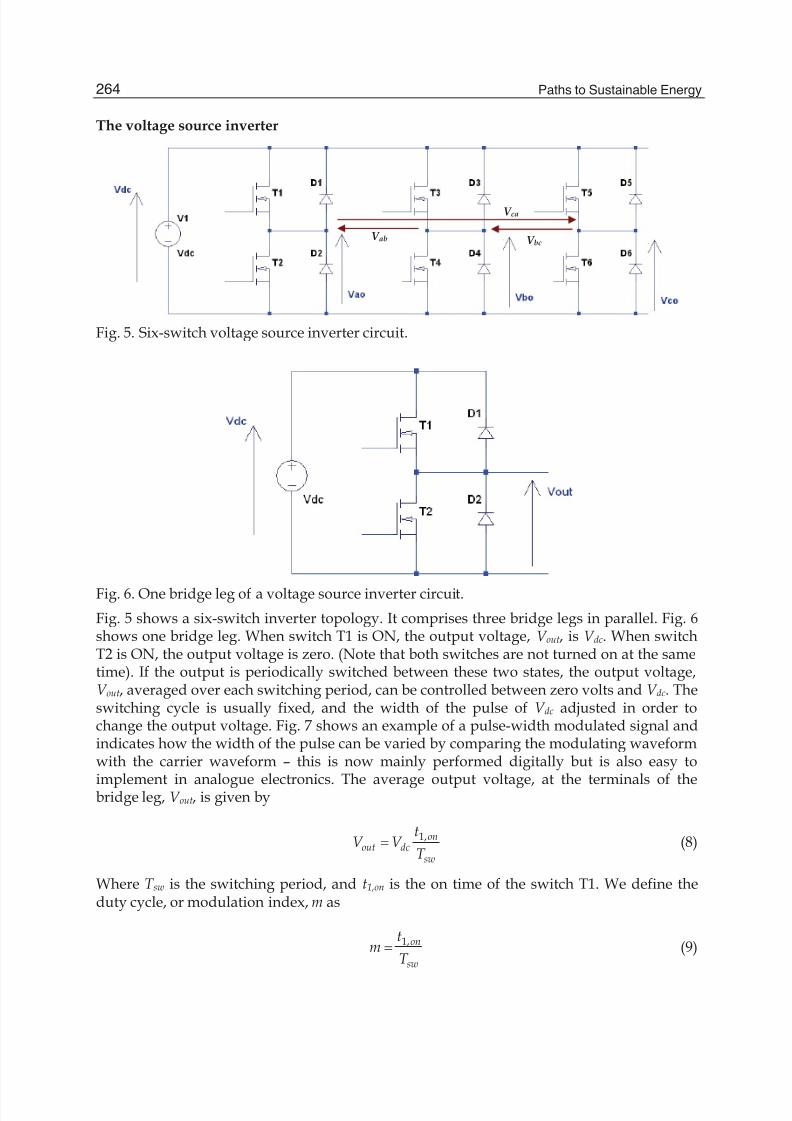
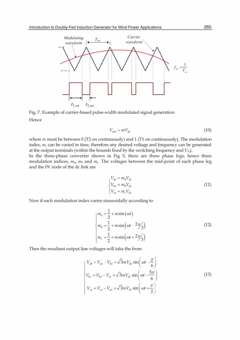
Fig. 5 shows a six-switch inverter topology. It comprises three bridge legs in parallel. Fig. 6shows one bridge leg. When switch T1 is ON, the output voltage, V out, is V dc. When switchT2 is ON, the output voltage is zero. (Note that both switches are not turned on at the sametime). If the output is periodically switched between these two states, the output voltage,V out, averaged over each switching period, can be controlled between zero volts and V dc. Theswitching cycle is usually fixed, and the width of the pulse of V dc adjusted in order tochange the output voltage. Fig. 7 shows an example of a pulse-width modulated signal andindicates how the width of the pulse can be varied by comparing the modulating waveformwith the carrier waveform – this is now mainly performed digitally but is also easy to
implement in analogue electronics. The average output voltage, at the terminals of thebridge leg, V out, is given by
1,onout dc
sw
tV V
T (8)
Where T sw is the switching period, and t1,on is the on time of the switch T1. We define theduty cycle, or modulation index, m as
1,on
sw
tm
T (9)
8/4/2019 Dfig Intro
http://slidepdf.com/reader/full/dfig-intro 7/20
Introduction to Doubly-Fed Induction Generator for Wind Power Applications 265
t sw
t on
Carrier
waveformModulating
waveform
t 1 ,on t 2 ,on
sw
swT
f 1
T sw
Fig. 7. Example of carrier-based pulse-width modulated signal generation.
Hence
out dcV mV (10)
where m must be between 0 (T2 on continuously) and 1 (T1 on continuously). The modulationindex, m, can be varied in time, therefore any desired voltage and frequency can be generatedat the output terminals (within the bounds fixed by the switching frequency and V dc).In the three-phase converter shown in Fig 5, there are three phase legs, hence threemodulation indices, ma, mb and mc. The voltages between the mid-point of each phase legand the 0V node of the dc link are
ao a dc
bo b dc
co c dc
V m V V m V
V m V
°®
° ¯
(11)
Now if each modulation index varies sinusoidally according to
1sin
21 2sin
321
2sin 32
a
b
c
m m t
m m t
m m t
Z
S Z
S Z
°°°
®°°
°̄
(12)
Then the resultant output line voltages will take the from
3 sin6
53 sin
6
3 sin2
ab ao bo dc
bc bo co dc
ca co ao dc
V V V mV t
V V V mV t
V V V mV t
S Z
S Z
S Z
§ · ¨ ¸°
© ¹°° § ·
® ¨ ¸© ¹°
° § · ° ¨ ¸
© ¹¯
(13)
8/4/2019 Dfig Intro
http://slidepdf.com/reader/full/dfig-intro 8/20
Paths to Sustainable Energy266
These are three-phase, balanced output line voltages, whose magnitude is controlled by m and whose output frequency and phase can be regulated by the frequency and phase of themodulating waveform. The modulating waveforms can be manipulated digitally usinghigh-performance microcontrollers or digital signal processors.
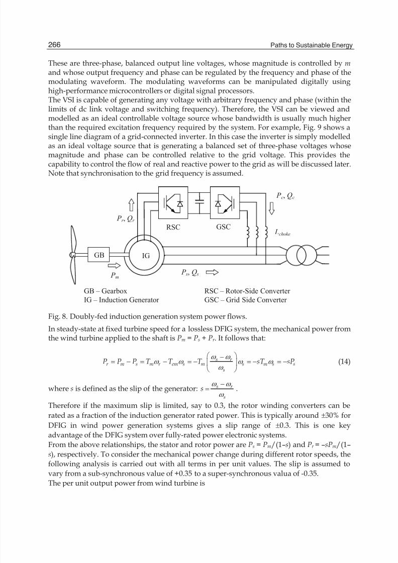
The VSI is capable of generating any voltage with arbitrary frequency and phase (within thelimits of dc link voltage and switching frequency). Therefore, the VSI can be viewed andmodelled as an ideal controllable voltage source whose bandwidth is usually much higherthan the required excitation frequency required by the system. For example, Fig. 9 shows asingle line diagram of a grid-connected inverter. In this case the inverter is simply modelledas an ideal voltage source that is generating a balanced set of three-phase voltages whosemagnitude and phase can be controlled relative to the grid voltage. This provides thecapability to control the flow of real and reactive power to the grid as will be discussed later.Note that synchronisation to the grid frequency is assumed.
IG
GB – Gearbox
IG – Induction Generator
RSC – Rotor-Side Converter
GSC – Grid Side Converter
GB
Lchoke
P s, Q s
RSC GSC P r , Qr
P c, Qc
P m
Fig. 8. Doubly-fed induction generation system power flows.
In steady-state at fixed turbine speed for a lossless DFIG system, the mechanical power fromthe wind turbine applied to the shaft is Pm = Ps + Pr . It follows that:
s r r m s m r em s m s m s s
s
P P P T T T sT sPZ Z
Z Z Z Z Z
§ · ¨ ¸
© ¹(14)
where s is defined as the slip of the generator: s r
s
sZ Z
Z
.
Therefore if the maximum slip is limited, say to 0.3, the rotor winding converters can be
rated as a fraction of the induction generator rated power. This is typically around r30% for
DFIG in wind power generation systems gives a slip range of r0.3. This is one key
advantage of the DFIG system over fully-rated power electronic systems.
From the above relationships, the stator and rotor power are Ps = Pm/(1–s) and Pr = –sPm/(1–
s), respectively. To consider the mechanical power change during different rotor speeds, the
following analysis is carried out with all terms in per unit values. The slip is assumed to
vary from a sub-synchronous value of +0.35 to a super-synchronous valua of -0.35.
The per unit output power from wind turbine is
8/4/2019 Dfig Intro
http://slidepdf.com/reader/full/dfig-intro 9/20
Introduction to Doubly-Fed Induction Generator for Wind Power Applications 267
3 _ _ m p pu wind puP C V (15)
Here we use the example wind turbine model in MATLAB (The Mathworks Inc., 2008):
5
21 3 4 6( , ) i
c
pi
cC c c c e cO O E E O O
§ · ¨ ¸© ¹
,3
1 1 0.0350.08 1iO O E E
, with the coefficients as c1 =
0.5176, c2 = 116, c3 = 0.4, c4 = 5, c5 = 21 and c6 = 0.0068. r
wind
R
V
Z O is the tip-speed ratio.
The maximum value of C p is 0.48 when E = 0 for O = 8.1. These are defined as base values forper unit calculations. Here base wind speed is 12 m/s, gear ratio is 10, rotor radius is 5.16m.When s = –0.2, C p is 0.48 then Pm is 1.0 p.u. ideally. Hence for 2 pole-pair generator,
s r
s
sZ Z
Z
, _ 1r pu sZ , 7
5 5.16(1 ) 6.751(1 ) (1 )
12r
wind
Rs s c s
V
Z S O
u .
Then at the base wind speed, the expression of Pm in terms of slip s is
5
21 4 6 7
1(1 )
0.48 0.48i
c
pm
i
C cP c c e c c sO
O
ª º§ ·« » ¨ ¸« »© ¹¬ ¼
,7
1 10.035
(1 )i c sO
. (16)
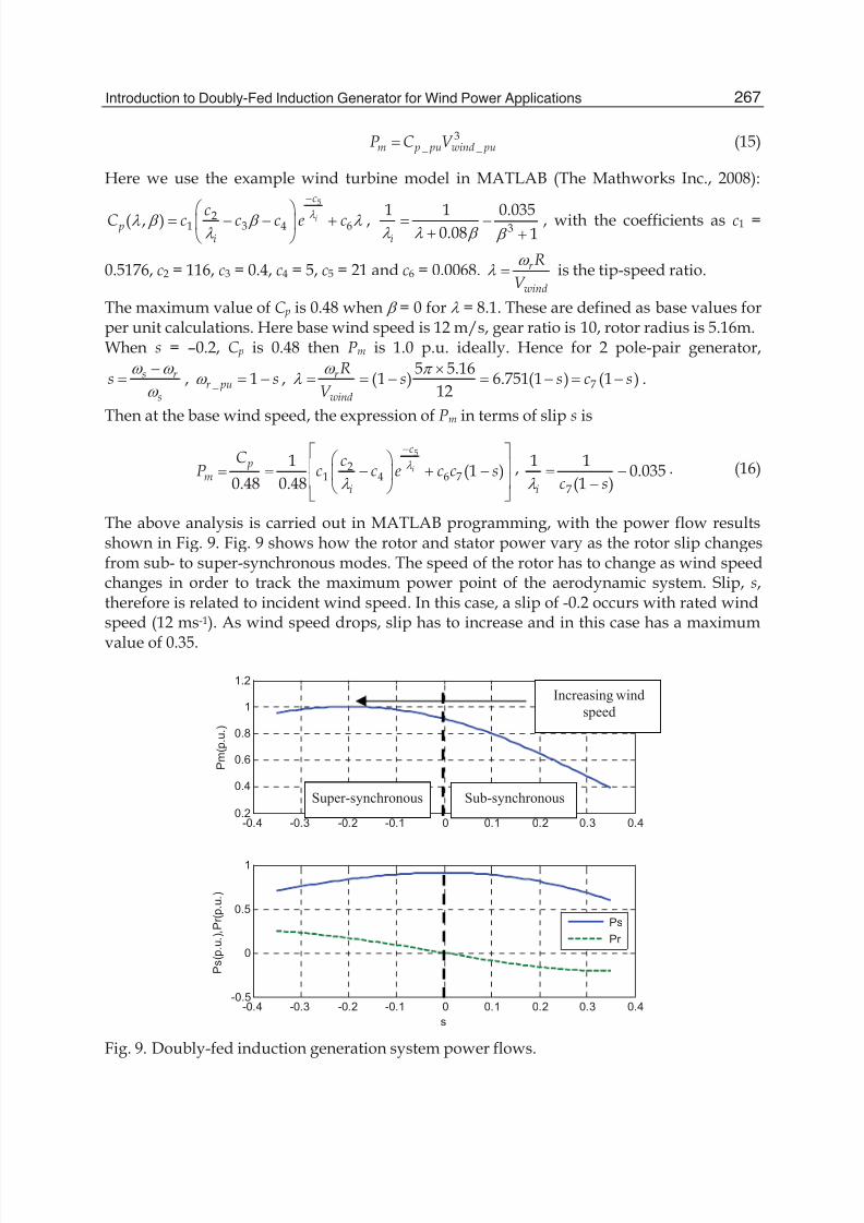
The above analysis is carried out in MATLAB programming, with the power flow resultsshown in Fig. 9. Fig. 9 shows how the rotor and stator power vary as the rotor slip changesfrom sub- to super-synchronous modes. The speed of the rotor has to change as wind speedchanges in order to track the maximum power point of the aerodynamic system. Slip, s,therefore is related to incident wind speed. In this case, a slip of -0.2 occurs with rated windspeed (12 ms-1). As wind speed drops, slip has to increase and in this case has a maximum
value of 0.35.
-0.4 -0.3 -0.2 -0.1 0 0.1 0.2 0.3 0.40.2
0.4
0.6
0.8
1
1.2
P m ( p . u . )
-0.4 -0.3 -0.2 -0.1 0 0.1 0.2 0.3 0.4-0.5
0
0.5
1
P s ( p . u . ) ,
P r ( p . u . )
s
Ps
Pr
Fig. 9. Doubly-fed induction generation system power flows.
Sub-synchronousSuper-synchronous
Increasing wind
speed
8/4/2019 Dfig Intro
http://slidepdf.com/reader/full/dfig-intro 10/20
Paths to Sustainable Energy268
It is clear that the mechanical power, Pm, reaches its peak at super-synchronous speed whens = -0.2. When rotating at the synchronous speed (s = 0), the DFIG supplies all the power viathe stator winding, with no active power flow in the rotor windings and their associatedconverters. Note that at s=0, the stator power is maximum. As the wind speed increases, the
rotational speed must also increase to maintain optimum tip-speed ratios. In suchcircumstances, the machine operates at super-synchronous speeds (s < 0). The mechanicalpower flows to the grid through both the stator windings and the rotor windings and theirconverter. For example, at s=-0.2, Ps is 0.8pu and Pr is 0.2 pu giving a total generated powerof 1pu. At lower wind speeds, the blades rotate at a sub-synchronous speed (s > 0). In suchcircumstances, the rotor converter system will absorb power from the grid connection toprovide excitation for rotor winding. For example, at s=0.2, Ps is 0.8pu but Pr is -0.2 pugiving a total generated power of 0.6pu. With such a control scheme it is possible to controlthe power extracted from the aerodynamic system such that the blade operates at theoptimum aerodynamic efficiency (thereby extracting as much energy is as possible) byadjusting the speed of rotation according to the incident wind speed.
The Rotor-Side Converter (RSC)
The rotor-side converter (RSC) applies the voltage to the rotor windings of the doubly-fedinduction generator. The purpose of the rotor-side converter is to control the rotor currentssuch that the rotor flux position is optimally oriented with respect to the stator flux in orderthat the desired torque is developed at the shaft of the machine.The rotor-side converter uses a torque controller to regulate the wind turbine output powerand the voltage (or reactive power) measured at the machine stator terminals. The power iscontrolled in order to follow a pre-defined turbine power-speed characteristic to track themaximum power point. The actual electrical output power from the generator terminals,added to the total power losses (mechanical and electrical) is compared with the reference
power obtained from the wind turbine characteristic. Usually, a Proportional-Integral (PI)regulator is used at the outer control loop to reduce the power error (or rotor speed error) tozero. The output of this regulator is the reference rotor current irqref that must be injected in therotor winding by rotor-side converter. This q-axis component controls the electromagnetictorque T e. The actual irq component of rotor current is compared with irqref and the error isreduced to zero by a current PI regulator at the inner control loop. The output of this currentcontroller is the voltage vrq generated by the rotor-side converter. With another similarlyregulated ird and vrd component the required 3-phase voltages applied to the rotor winding areobtained. The generic power control loop is illustrated in the next section.
The Grid-Side Converter (GSC)
The grid-side converter aims to regulate the voltage of the dc bus capacitor. Moreover, it isallowed to generate or absorb reactive power for voltage support requirements. Thefunction is realized with two control loops as well: an outer regulation loop consisting of adc voltage regulator. The output of the dc voltage regulator is the reference current icdref forthe current regulator. The inner current regulation loop consists of a current regulatorcontrolling the magnitude and phase of the voltage generated by converter from the icdref produced by the dc voltage regulator and specified q-axis icqref reference.
Converter losses
The losses of the converters can be divided into switching losses and conducting losses. The
switching losses of the transistors are the turn-on and turn-off losses. For the diode the
8/4/2019 Dfig Intro
http://slidepdf.com/reader/full/dfig-intro 11/20
Introduction to Doubly-Fed Induction Generator for Wind Power Applications 269
switching losses mainly consist of turn-off losses, i.e., reverse-recovery energy. The turn-on
and turn-off losses for the transistor and the reverse-recovery energy loss for a diode can befound from data sheets. The conducting losses arise from the current through the transistors
and diodes. The transistor and the diode can be modeled as constant voltage drops, and a
resistance in series. The switching losses of the transistor can be considered to be proportionalto the current, for a given dc-link voltage. For a given dc-link voltage and switching frequency,the switching losses of the IGBT and diode can be modeled as a constant voltage drop that is
independent of the current rating of the valves (Petersson, 2005).
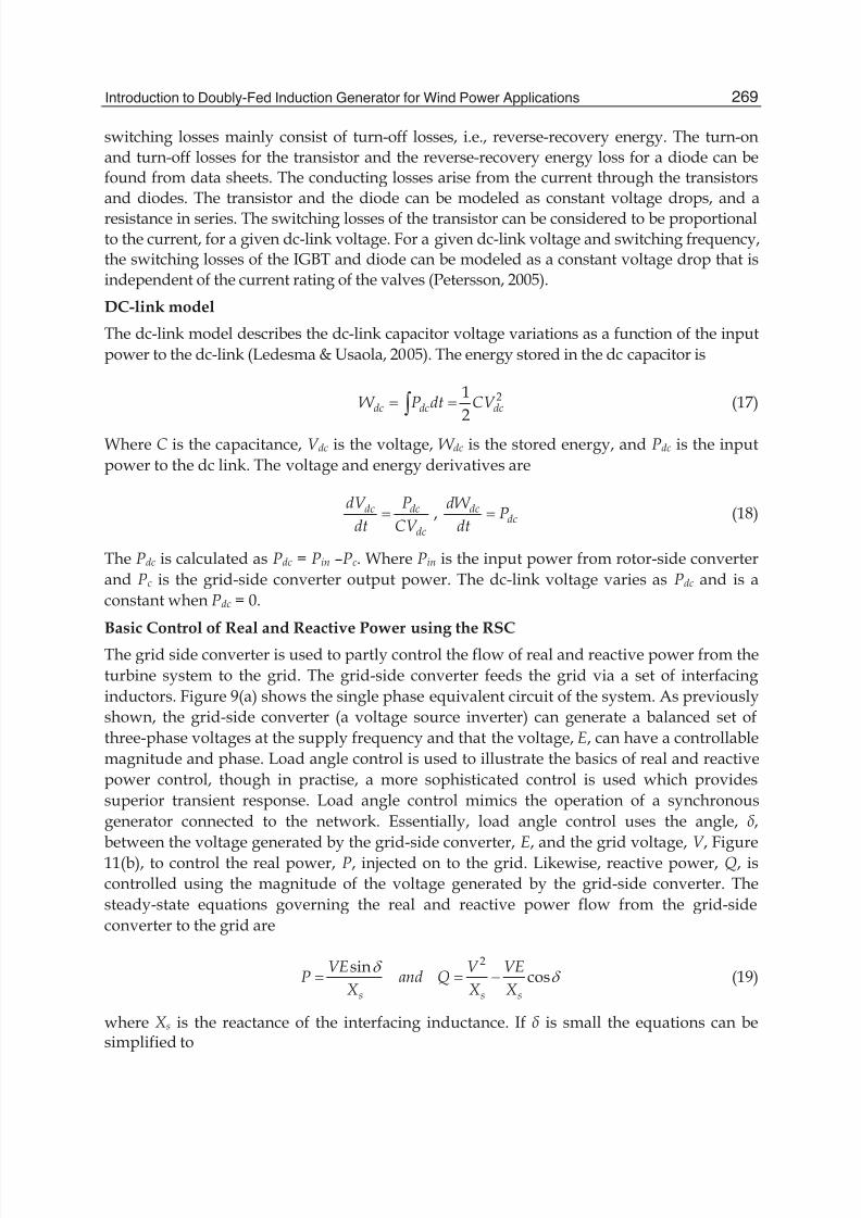
DC-link model
The dc-link model describes the dc-link capacitor voltage variations as a function of the input
power to the dc-link (Ledesma & Usaola, 2005). The energy stored in the dc capacitor is
21
2dc dc dcW P dt CV ³ (17)
Where C is the capacitance, V dc is the voltage, W dc is the stored energy, and Pdc is the input
power to the dc link. The voltage and energy derivatives are
dc dc
dc
dV P
dt CV , dc
dc
dW P
dt (18)
The Pdc is calculated as Pdc = Pin –Pc. Where Pin is the input power from rotor-side converter
and Pc is the grid-side converter output power. The dc-link voltage varies as Pdc and is a
constant when Pdc = 0.
Basic Control of Real and Reactive Power using the RSC
The grid side converter is used to partly control the flow of real and reactive power from the
turbine system to the grid. The grid-side converter feeds the grid via a set of interfacing
inductors. Figure 9(a) shows the single phase equivalent circuit of the system. As previously
shown, the grid-side converter (a voltage source inverter) can generate a balanced set of
three-phase voltages at the supply frequency and that the voltage, E, can have a controllable
magnitude and phase. Load angle control is used to illustrate the basics of real and reactive
power control, though in practise, a more sophisticated control is used which provides
superior transient response. Load angle control mimics the operation of a synchronous
generator connected to the network. Essentially, load angle control uses the angle, ,
between the voltage generated by the grid-side converter, E, and the grid voltage, V , Figure
11(b), to control the real power, P, injected on to the grid. Likewise, reactive power, Q, is
controlled using the magnitude of the voltage generated by the grid-side converter. The
steady-state equations governing the real and reactive power flow from the grid-side
converter to the grid are
2sincos
s s s
VE V VEP and Q
X X X
G G (19)
where X s is the reactance of the interfacing inductance. If is small the equations can besimplified to
8/4/2019 Dfig Intro
http://slidepdf.com/reader/full/dfig-intro 12/20
Paths to Sustainable Energy270
2
s s s
VE V VEP and Q
X X X
G (20)
Showing that P can be controlled using load angle, , and Q can be controlled using the
magnitude of E. Interfacing inductance must be used to couple the output of the grid-sideconverter shown in Figure 8 to the grid. The inductor is sized according to the rating of theconverter. Typically, the system will have a transformer on the turbine side of the point ofcommon coupling (PCC). In addition, at the point of connection there is usually the need fora substation which includes whatever equipment is required by local network codes, forexample, plant to disconnect the turbine under fault conditions.The combination of control and power electronics enables the grid-side converter to producethe necessary voltage magnitude, E, and load angle, , in order to meet a required Pc and Qc demand set by the main system controller. The controller has to be able to synchronise to thegrid frequency and phase, in order to connect and supply power. This is typically carriedout using some form of phase-locked loop.
E/G
jXs
loado
V
=V/0a
Ia
I
I
G IV
IXs
E
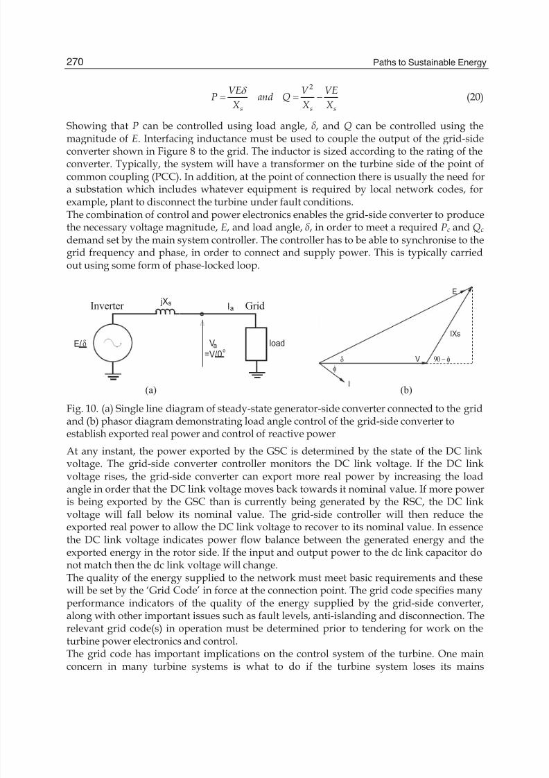
(a) (b)
GridInverter
Fig. 10. (a) Single line diagram of steady-state generator-side converter connected to the gridand (b) phasor diagram demonstrating load angle control of the grid-side converter toestablish exported real power and control of reactive power
At any instant, the power exported by the GSC is determined by the state of the DC linkvoltage. The grid-side converter controller monitors the DC link voltage. If the DC linkvoltage rises, the grid-side converter can export more real power by increasing the loadangle in order that the DC link voltage moves back towards it nominal value. If more poweris being exported by the GSC than is currently being generated by the RSC, the DC linkvoltage will fall below its nominal value. The grid-side controller will then reduce theexported real power to allow the DC link voltage to recover to its nominal value. In essence
the DC link voltage indicates power flow balance between the generated energy and theexported energy in the rotor side. If the input and output power to the dc link capacitor donot match then the dc link voltage will change.The quality of the energy supplied to the network must meet basic requirements and thesewill be set by the ‘Grid Code’ in force at the connection point. The grid code specifies manyperformance indicators of the quality of the energy supplied by the grid-side converter,along with other important issues such as fault levels, anti-islanding and disconnection. Therelevant grid code(s) in operation must be determined prior to tendering for work on theturbine power electronics and control.The grid code has important implications on the control system of the turbine. One mainconcern in many turbine systems is what to do if the turbine system loses its mains
8/4/2019 Dfig Intro
http://slidepdf.com/reader/full/dfig-intro 13/20
Introduction to Doubly-Fed Induction Generator for Wind Power Applications 271
connection, say, for example, because of a network fault. Without a mains connection theturbine is unable to export energy. If the generator-side controller continues to generatepower, the DC link capacitance will be over charged. Therefore, a grid fault will require thegenerator to stop generating energy, which then means that there is no longer a restraining
torque to control the blade speed. In a wind turbine, a loss of supply will cause an over-speed condition, as the blade system will accelerate due to the aerodynamic torqueproduced by the blades. Shorting resistors, or a crowbar circuit, are often switched acrossthe rotor circuit of the generator in order that the energy generated by the blade system canbe absorbed and the over-speed condition controlled to a safe and manageable level. Inaddition, there are often aerodynamic (pitch control) and mechanical braking mechanismsincluded in wind turbines as an additional over-speed safety measure.
4. Control system
Nomenclature
vG
, iG
, \ G
Voltage, current and flux vectors.
Rs, Rr Stator, rotor winding resistances.Ls, Lr , Lls, Llr Stator, rotor winding self- and leakage inductances.Lm Magnetizing inductance.
Z s, Z r , Z slip Synchronous, rotor and slip angular frequencies.P, Q Active and reactive power. s, r Stator and rotor subscripts. g Grid-side value subscripts.c Converter value subscripts.d, q d-axis and q-axis component subscripts.
n Nominal value subscript.ref Reference value superscript.This section will detail the vector-control techniques used for the independent control oftorque and rotor excitation current in the DFIG and decouple control of the active andreactive power supplied to the grid. The vector control for the generator can be embeddedin an optimal power tracking controller for maximum energy capture in a wind powerapplication. By controlling the active power of the converter, it is possible to vary therotational speed of the generator, and thus the speed of the rotor of the wind turbine. Thiscan then be used to track the optimum tip-speed ratio as the incident wind speed changesthereby extracting the maximum power from the incident wind. The grid-side convertercontrol gives potential for optimising the grid integration with respect to steady-state
operation conditions, power quality and voltage stability.
4.1 Rotor-side converter control
The rotor-side converter (RSC) provides the excitation for the induction machine rotor. Withthis PWM converter it is possible to control the torque hence the speed of the DFIG and alsothe power factor at the stator terminals. The rotor-side converter provides a varyingexcitation frequency depending on the wind speed conditions. The induction machine iscontrolled in a synchronously rotating dq-axis frame, with the d-axis oriented along thestator-flux vector position in one common implementation. This is called stator-fluxorientation (SFO) vector control. In this way, a decoupled control between the electrical

8/4/2019 Dfig Intro
http://slidepdf.com/reader/full/dfig-intro 14/20
Paths to Sustainable Energy272
torque and the rotor excitation current is obtained. Consequently, the active power andreactive power are controlled independently from each other.There are other options for directional rotating frames. Orientation frames applied intraditional vector control of induction machines such as rotor-flux orientation and
magnetizing-flux orientation, can also be utilised (Vas, 1990). Additionally, the stator-voltage orientation (SVO) is also commonly-used in DFIG vector controller, as contrast withSFO (Muller et al., 2002).To describe the control scheme, the general Park’s model of an induction machine isintroduced. Using the motor convention in a static stator-oriented reference frame, withoutsaturation, the voltage vector equations are
ss s s
dv R i
dt
\
G
G
G
(21)
r r r r r
dv R i jdt
\
Z\
G
G
G G
(22)
where svG
is the stator voltage imposed by the grid. The rotor voltage r vG
is controlled by the
rotor-side converter and used to perform generator control.The flux vector equations are
s s s m r L i L i\ G G
G
(23)
r m s r r L i L i\ G G
G
(24)
where Ls and Lr are the stator and rotor self-inductances: s m lsL L L , r m lr L L L .
Under stator-flux orientation (SFO), in dq-axis component form, the stator flux equations are:
0sd s sd m rd s m ms
sq
L i L i L i\ \
\
°® °̄
(25)
Defining leakage factor2
1 m
s r
L
L LV and equivalent inductance as
2m
os
LL
L . The rotor
voltage and flux equations are (scaled to be numerically equal to the ac per-phase values):
( )
rdrd r rd r slip r rq
rqrq r rq r slip o ms r rd
di
v R i L L idtdi
v R i L L i L idt
V Z V
V Z V
°°®° °̄
(26)
2m
rd ms r rds
rq r rq
Li L i
L
L i
\ V
\ V
°®° ¯
(27)
where the slip angular speed is slip s r Z Z Z .

8/4/2019 Dfig Intro
http://slidepdf.com/reader/full/dfig-intro 15/20
Introduction to Doubly-Fed Induction Generator for Wind Power Applications 273
The stator flux angle is calculated from
( )
( )
s s s s
s s s s
v R i dt
v R i dt
D D D
E E E
\
\
°®
°̄
³
³
, 1tans
s
s
E
D
\ T
\
§ · ¨ ¸
© ¹
(28)
where T s is the stator-flux vector position.The control scheme of the rotor-side converter is organised in a generic way with two seriesof two PI-controllers. Fig. 11 shows a schematic block diagram for the rotor-side convertercontrol. The reference q-axis rotor current irq* can be obtained either from an outer speed-control loop or from a reference torque imposed on the machine. These two options may betermed a speed-control mode or torque-control mode for the generator, instead of regulatingthe active power directly. For speed-control mode, one outer PI controller is to control thespeed error signal in terms of maximum power point tracking. Furthermore, another PIcontroller is added to produce the reference signal of the d-axis rotor current component to
control the reactive power required from the generator. Assuming that all reactive power tothe machine is supplied by the stator, the reference value ird* may set to zero. The switchingdynamics of the IGBT-switches of the rotor converter are neglected and it is assumed thatthe rotor converter is able to follow demand values at any time.The control system requires the measurement of the stator and rotor currents, stator voltageand the mechanical rotor position. There is no need to know the rotor-induced EMF, as isthe case for the implementation with naturally commutated converters. Since the stator isconnected to the grid, and the influence of the stator resistance is small, the statormagnetising current ims can be considered constant (Pena et al., 1996).Rotor excitation current control is realised by controlling rotor voltage. The ird and irq errorsignals are processed by associated PI controllers to give vrd and vrq, respectively.
PI PI
PI
e j(s-r )
2/3 PWM
2/3
2/3
e-js
1/ Lo
Q s
Q* s
+
i*rd +
i*rq
+
+
+
+
vrd ' +
vrq' v*rq
v*rd v
*r D
v*r E
v*ra,b,c
DC-link
T r
Z slip
ird
irq
i sD , E
ira,b,c
v sa,b,c
ir D , E
PI
Z r
Z *r
+
IG
e-j(s-r )
encoder
i sa,b,c
v sD , E Stator fluxcalc.\ sD , E
T s
+
d/dt
Fluxanglecalc.
d/dtZ s
\ sd ims
Z slip V Lr irq
Z slip ( Lo ims+V Lr ird )
Fig. 11. Vector control structure for rotor-side converter.
8/4/2019 Dfig Intro
http://slidepdf.com/reader/full/dfig-intro 16/20
Paths to Sustainable Energy274
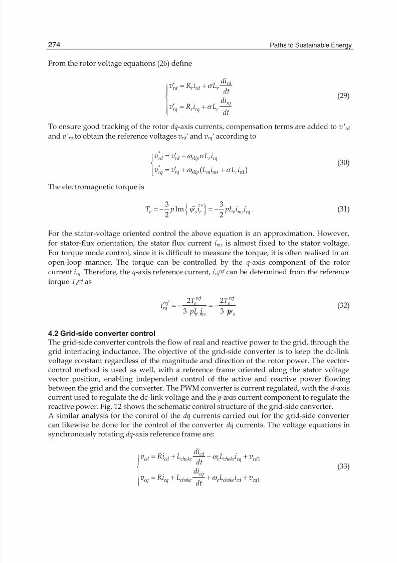
From the rotor voltage equations (26) define
rdrd r rd r
rqrq r rq r
div R i L
dt
div R i L
dt
V
V
c °°
®° c °̄
(29)
To ensure good tracking of the rotor dq-axis currents, compensation terms are added to vrd
and vrq to obtain the reference voltages vrd* and vrq* according to
*
* ( )
rd rd slip r rq
rq rq slip m ms r rd
v v L i
v v L i L i
Z V
Z V
c °®
c °̄(30)
The electromagnetic torque is
^ `*3 3Im
2 2e s r o ms rqT p i pL i i\
G
G
. (31)
For the stator-voltage oriented control the above equation is an approximation. However,
for stator-flux orientation, the stator flux current ims is almost fixed to the stator voltage.
For torque mode control, since it is difficult to measure the torque, it is often realised in an
open-loop manner. The torque can be controlled by the q-axis component of the rotor
current irq. Therefore, the q-axis reference current, irqref can be determined from the reference
torque T eref as
2 2
3 3
ref ref ref e erq
o ms s
T T i
pL i p\ (32)
4.2 Grid-side converter control
The grid-side converter controls the flow of real and reactive power to the grid, through thegrid interfacing inductance. The objective of the grid-side converter is to keep the dc-linkvoltage constant regardless of the magnitude and direction of the rotor power. The vector-control method is used as well, with a reference frame oriented along the stator voltagevector position, enabling independent control of the active and reactive power flowingbetween the grid and the converter. The PWM converter is current regulated, with the d-axis
current used to regulate the dc-link voltage and the q-axis current component to regulate thereactive power. Fig. 12 shows the schematic control structure of the grid-side converter.A similar analysis for the control of the dq currents carried out for the grid-side convertercan likewise be done for the control of the converter dq currents. The voltage equations insynchronously rotating dq-axis reference frame are:
1
1
cdcd cd choke e choke cq cd
cqcq cq choke e choke cd cq
div Ri L L i v
dtdi
v Ri L L i vdt
Z
Z
°°®° °̄
(33)

8/4/2019 Dfig Intro
http://slidepdf.com/reader/full/dfig-intro 17/20
Introduction to Doubly-Fed Induction Generator for Wind Power Applications 275
The angular position of the grid voltage is calculated as 1tanc
e ec
vdt
v
E
D
T Z § · ¨ ¸
© ¹³
PI PI
PI
e je
2/3 PWM
Voltage anglecalculation
2/3e-je
2/3e je
e Lchoke
e Lchoke
V DC
V * DC
+
i*cd +
i*cq +
+
++
vcd '
vcq' v*cq
v*cd v
*cD
v*c E
v*ca,b,c
DC-link
T e
vcd
icd
icq icD , E
vca,b,c
ica,b,c
icD , E
Lchoke
Fig. 12. Vector control structure for grid-side converter.
where vcD and vc E are the converter grid-side voltage stationary frame components.
The d-axis of the reference frame is aligned with the grid voltage angular position T e. Sincethe amplitude of the grid voltage is constant, vcq is zero and vcd is constant. The active andreactive power will be proportional to icd and icq respectively.
Assume the grid-side transformer connection is star, the converter active and reactive powerflow is
3( ) 3
3( ) 3
c cd cd cq cq cd cd
c cd cq cq cd cd cq
P v i v i v i
Q v i v i v i
°®
°̄(34)
Which demonstrates that the real and active powers from the grid-side converter arecontrolled by the icd and icq components of current respectively. To realise decoupled control,similar compensations are introduced likewise in equation (30):
*
*
( )
( )cd cd e choke cq d
cq cq e choke cd
v v L i v
v v L i
Z
Z
c °®
c °̄(35)
The reference voltage vcd* and vcq* are then transformed by inverse-Park transformation to give3-phase voltage vcabc* for the final PWM signal generation for the converter IGBT switching.
5. Application issues
5.1 Industrial applications
The DFIG system costs more than fixed-speed induction generators without converters.
However, the performance and controllability are excellent in comparison with fixed-

8/4/2019 Dfig Intro
http://slidepdf.com/reader/full/dfig-intro 18/20
Paths to Sustainable Energy276
speed induction generator systems; they capture more wind energy, they exhibit a higher
reliability gear system, and high-quality power supplied to the grid. It saves investment
on full-rated power converters, and soft-starter or reactive power compensation devices
(fixed-speed systems). Modern wind farms, with a nominal turbine power up to several
MWs, are a typical case of DFIG application. Besides this, other applications for the DFIG
systems are, for example, flywheel energy storage system, stand-along diesel systems,
pumped storage power plants, or rotating converters feeding a railway grid from a
constant frequency utility grid.
5.2 Braking systems
Braking systems for a wind turbine generation system must be able to reduce the speed of
the aerodynamic rotor during abnormal scenarios, such as over speed, maintenance or
fault conditions. Wind turbine design standards require two independent brakes which
must be capable of reducing the wind turbine to a safe rotational speed in all anticipated
wind speeds and fault conditions (Craig et al., 1998). There are usually combinedconventional mechanical shaft (disk) brakes and aerodynamic brakes (for example,
pitching mechanisms) for wind turbine brake systems. For a rapid response,
electrodynamic braking can be used but only in the event that the electrical systems are
operational. However, it has to be used in combination with a mechanical parking brake
in cases when the rotor cannot be allowed to idle at a low rotational speed. Moreover, it
cannot hold the rotor at standstill.
5.3 Converter protection systems
The prevalent DFIG converter protection scheme is crowbar protection. A crowbar is a
set of resistors that are connected in parallel with the rotor winding on occurrence of aninterruption. The crowbar circuit bypasses the rotor-side converter. The active crowbar
control scheme connects the crowbar resistance when necessary and disables it toresume DFIG control. A braking resistor (DC-chopper) can be connected in parallel with
the DC-link capacitor to limit the overcharge during low grid voltage. This protects the
IGBTs from overvoltage and can dissipate energy, but this has no effect on the rotor
current. It is also used as protection for the DC-link capacitor in full rated convertertopologies, for example, permanent magnet synchronous generators. In a similar way to
the series dynamic braking resistor, which has been used in the stator side ofgenerators, a dynamic resistor is proposed to be put in series with the rotor (series
dynamic resistor) and this limits the rotor over-current (Yang et al., 2010). Being
controlled by a power-electronic switch, in normal operation, the switch is on and theresistor is bypassed; during fault conditions, the switch is off and the resistor is
connected in series to the rotor winding. The rotor equivalent circuit is shown with all
the above protection schemes in Fig. 13.
6. Summary
The DFIG system applied to wind power generation has gained considerable academic
attention and industrial application during the past 10 years. In practical applications,power levels are currently reaching 3-5MW and the DFIG is gradually maturing as a

8/4/2019 Dfig Intro
http://slidepdf.com/reader/full/dfig-intro 19/20
Introduction to Doubly-Fed Induction Generator for Wind Power Applications 277
Rr V Lr
r
rovG
Series Dynamic Resistor
r
r vG
+
Rotor
Series-Resistor
+
Crowbar
Shunt-Resistor
r
r iG
RSC
DC-link
Shunt-Resistor
DC-Chopper
Bypass Switch
Fig. 13. DFIG rotor equivalent circuit with all protection schemes shown.
technology for variable-speed wind energy utilisation. In this chapter, the steady-stateinduction machine operation, back-to-back converter system and basic vector-control
techniques are summarised, with practical application issues briefly summarised. Although
topologies of new systems with improved performance are emerging both in academia and
industry (Chen et al., 2009), DFIG is the most competitive option in terms of balance
between the technical performance and economic costs.
7. References
Chen, Z.; Guerrero, J.M. & Blaabjerg, F. (2009). A review of the state of the art of power
electronics for wind turbines, IEEE Trans. Power Electron., Vol. 24, No. 8, August
2009, 1859-1875, ISSN 0885-8993Craig, L.M.; Saad-Saoud, Z. & Jenkins, N. (1998). Electrodynamic braking of wind
turbines, IEE Proc.-Electr. Power Appl., Vol. 145, No. 2, March 1998, 140-146,
ISSN
Ledesma, P. & Usaola, J. (2005). Doubly fed induction generator model for transient
stability analysis, IEEE Trans. Energy Conver., Vol. 20, No. 2, June 2005, 388-397,
ISSN 0885-8969
Muller, S.; Deicke, M. & De Doncker, R.W. (2002). Doubly fed induction generator
systems for wind turbines, IEEE Ind. Appl. Magazine, Vol., No., May/June 2002,
26-33, ISSN 1077-2618/02
Pena, R.; Clare, J.C. & Asher, G.M. (1996). Doubly fed induction generator usingback-to-back PWM converters and its application to variable-speed
wind-energy generation, IEE Proc.-Electr. Power Appl., Vol. 143, No. 3, May
1996, 231-241, ISSN
Petersson, A. (2005). Analysis, modeling and control of doubly-fed induction generators for
wind turbines, Chalmers University of Technology, Goteborg, Sweden, 2005.
The Mathworks Inc. (2008). MATLAB (R2008a), Product Help.
Vas, P. (1990). Vector Control of AC Machines, Oxford University Press, ISBN 0 19 859370
8, Oxford, UK.

8/4/2019 Dfig Intro
http://slidepdf.com/reader/full/dfig-intro 20/20
Paths to Sustainable Energy278
Yang, J.; Fletcher, J.E. & O’Reilly, J. (2010). A Series-dynamic-resistor-based converter
protection scheme for doubly-fed induction generator during various fault
conditions, IEEE Trans. Energy Conver., Vol. 25, No. 2, June 2010, 422-432, ISSN
0885-8969