Embed Size (px)
Citation preview
International Journal of Solids and Structures 51 (2014) 3549–3556
Contents lists available at ScienceDirect
International Journal of Solids and Structures
journal homepage: www.elsevier .com/locate / i jsols t r
Strain gradient effects in periodic flat punch indenting at small scales
http://dx.doi.org/10.1016/j.ijsolstr.2014.06.0090020-7683/� 2014 Elsevier Ltd. All rights reserved.
⇑ Corresponding author. Tel.: +45 4525 4258; fax: +45 4593 1475.E-mail address: [email protected] (K.L. Nielsen).
K.L. Nielsen a,⇑, C.F. Niordson a, J.W. Hutchinson b
a Department of Mechanical Engineering, Solid Mechanics, Technical University of Denmark, DK-2800 Kgs. Lyngby, Denmarkb School of Engineering and Applied Sciences, Harvard University, 29 Oxford Street, Cambridge, MA 02138, USA
a r t i c l e i n f o a b s t r a c t
Article history:Received 17 January 2014Received in revised form 15 May 2014Available online 14 June 2014
Keywords:Higher order theorySize effectsIndentationImprinting
Experiments on soft polycrystalline aluminum have yielded evidence that, besides the required punchload, both the size and shape of imprinted features are affected by the scale of the set-up, e.g. substantialdetails are lost when the characteristic length is on the order of 10 lm. The objective of this work is toclarify the role played by strain gradients on this issue, and to shed light on the underlying mechanisms.For this, indentation by a periodic array of flat punch indenters is considered, and a gradient enhancedmaterial model that allows for a numerical investigation of the fundamentals are employed. During a lar-gely non-homogeneous deformation, the material is forced up in between the indenters so that an arrayof identical imprinted features is formed once the tool is retreated. It is confirmed that the additionalhardening owing to plastic strain gradients severely affects both the size and shape of these imprintedfeatures. In particular, this is tied to a large increase in the mean contact pressure underneath the punch,which gives rise to significant elastic spring-back effects during unloading.
� 2014 Elsevier Ltd. All rights reserved.
1. Introduction
Flat punch indenting of elastic–plastic solids has earnedrenewed interest in recent years as a way of rapidly mass produc-ing micron surface features. To achieve high throughput, thesurface punching has been evolved into a continuous micro-man-ufacturing process that relies on imprinting/molding by rolling(referred to as roll-molding, (Lu and Meng, 2013)). However, theunderlying mechanisms remains the same. In its simplest form, aflat patterned indentor is pressed into the underlying materialand thereby leaving an imprint in the plastically deformed surfaceonce retreated. This classical problem is well-established in the lit-erature, not the least owing to the slip-line field solutions for anrigid perfectly plastic solid by Hill (1950), which has been verifiedin numerical studies employing conventional plasticity (Nepershin,2002). Their efforts, along with corresponding studies on pyrami-dal (Vickers or Knoop), spherical (Brinell) and wedge indentation,have yielded important in-sight into the underlying mechanics,and indentation has become a widely used standard technique inmaterial testing at all scales. It is, however, recognized that indent-ing at small scales results in increased yield resistance, for materi-als that deform plastically by dislocation movement, whencompared to large scale testing.
When employing indenting (or punching) for manufacturingpurposes, the surface imprint is often aimed to represent a coun-terpart to the indenter as closely as possible. However, a perfectmatch is complicated by effects such as elastic spring-back, straingradient hardening, material inertia, and viscosity. Redesign of thepunch may improve the imprint, but in general perfectly sharpedges cannot be achieved and some surface curvature must beaccepted; this with little noticeable different at large scales. How-ever, deviations from perfectly sharp edges become increasinglyevident when the punching process is down-scaled to do micro-manufacturing. Unfortunately, the goal of attaining sharp edges,and abrupt variations in the deformed geometry, are associatedwith large strain gradients, which lead to the before mentionedincreased hardening at micron scale. The explanation for this isnow generally accepted to lie in the concept of Geometrically Nec-essary Dislocations (GND’s). When large plastic strain gradientsappear GND’s must be stored (Ashby, 1970), and this gives rise tofree energy associated with the local stress field of the GND’s, as-well as increased dissipation when the GND’s move in the lattice.At small scales, GND’s can become a substantial portion of the totaldislocation density which is normally dominated by so-called Sta-tistically Stored Dislocations (SSD’s) at larger scale. Thus, a largeramount of energy is required to deform the material at small scalesin the presence of gradients, and this leads to an apparent increasein yield stress and strain hardening. To accurately predict theshape and size of imprints made during micro-manufacturing the
3550 K.L. Nielsen et al. / International Journal of Solids and Structures 51 (2014) 3549–3556
employed material model must therefore represent stresses overthe full range of length scales involved.
A vast amount of theoretical literature seeking to encapsulatethe experimentally observed gradient effects at micron scale hasbeen put forward, counting both phenomenological models(Aifantis, 1984; Fleck and Hutchinson, 1997, 2001; Gudmundson,2004; Gurtin and Anand, 2005; Lele and Anand, 2008; Fleck andWillis, 2009a,b), and micro-mechanics based models (Gao et al.,1999; Huang et al., 1999; Gurtin, 2002; Qiu et al., 2003). The higherorder theory by Fleck and Willis (2009b) is employed in the currentstudy, and the concept of higher order stresses, work conjugate tothe strain gradients, is thus adopted to widen the range of lengthscales for which the model is valid. The objective is to model anexperiment on soft polycrystalline aluminum at small scale, wherethe impression made by a periodic array of micro-indenters devi-ates substantially from that observed at larger scales. Throughnumerical modeling it is the aim to clarify the influence of plasticstrain gradients. Moreover, by including unloading the elasticspring-back can be quantified when compared to the surface shapeat maximum indentation depth. By choosing a material lengthparameter of LD ¼ 1 lm, it is demonstrated that significant gradi-ent effects should be expected for imprinted features with a char-acteristic length on the order of 10 lm and below. This choice oflength parameter are in line with the estimates for the lengthparameter put forward by Hutchinson (2000) (LD � 0:25� 5 lm,depending on the gradient type being stretch or rotational), andrecently by Danas et al. (2012) (LD � 0:5� 1:5lm).
The paper is structured as follows. The considered boundaryvalue problem is summarized in Section 3, while the materialmodel formulation and numerical procedure are briefly outlinedin Sections 2 and 4. A modeling framework capable of predictingthe rate-independent material response is employed, and theresults are laid out in Section 5. Focus is on shape and size changesto the imprints made onto the plastically deformed surface, as-wellas on changes to the loading history due to strain gradient effects.Some concluding remarks are given in Section 6.
Table 1Mechanical properties.
Parameter Significance Value
ry=E Uniaxial yield strain 0.001m Poisson’s ratio 0.3N Strain hardening exponent 0.05–0.2
2. Strain gradient material models
In spite of indentation being an inherent finite strain problem, asmall strain version of the strain gradient plasticity theory by Fleckand Willis (2009b) (tensorial version) is employed in this study asa first approximation. This is considered sufficient for the smallindentation depths analyzed. A compact summary of the rate-inde-pendent model formulation published by Nielsen and Niordson(2013, 2014) is given below. Throughout, Einstein’s summationrule is utilized in the tensor equations and ðÞ;i denotes partial dif-ferentiation with respect to the spatial coordinate xi.
2.1. Fundamentals of the Fleck–Willis strain gradient theory
A small strain formulation is employed. The total strain rate isdetermined from the gradients of the displacement rates;_eij ¼ ð _ui;j þ _uj;iÞ=2, and decomposed into an elastic part, _ee
ij, and aplastic part, _ep
ij, so that; _eij ¼ _eeij þ _ep
ij. For a higher order gradientdependent material, involving higher order stresses, the principleof virtual work reads (Gudmundson, 2004)Z
Vrijdeij þ ðqij � sijÞdep
ij þ sijkdepij;k
� �dV
¼Z
STidui þ tijdep
ij
� �dS: ð1Þ
Here, rij is the symmetric Cauchy stress tensor, andsij ¼ rij � dijrkk=3 its deviatoric part. In addition to conventionalstresses, the principle of virtual work incorporates the so-called
micro-stress tensor, qij (work-conjugate to the plastic strain, epij),
and the higher order stress tensor, sijk (work-conjugate to plasticstrain gradients, ep
ij;k). The right-hand side of Eq. (1) therebyincludes both conventional tractions, Ti ¼ rijnj, and higher ordertractions, tij ¼ sijknk, with nk denoting the outward normal to thesurface S, which bounds the volume V.
The mechanisms associated with dislocation movement and/orstorage of geometrically necessary dislocations (GND’s) (Ashby,1970; Gurtin, 2002; Ohno and Okumara, 2007) have been incorpo-rated into the current higher order theory by assuming the micro-stress, qij, and higher order stresses, sijk, to have a dissipative partonly, such that; qij ¼ qD
ij , and sijk ¼ sDijk. Thus, assuming the form
of the free energy to be
W ¼ 12ðeij � ep
ijÞLijklðekl � epklÞ ð2Þ
the conventional stresses are derived as; rij ¼ @W=@eeij ¼
Lijklðekl � epklÞ, where Lijkl is the isotropic elastic stiffness tensor. In
this study, all energetic gradient contributions are omitted. The dis-sipative stress quantities in the plastic regions read (Gudmundson,2004; Fleck and Willis, 2009b)
qDij ¼
23
rC
_Ep_ep
ij; and sDijk ¼
rC
_EpðLDÞ2 _ep
ij;k ð3Þ
with rC and _Ep identified as the effective stress and the associatedeffective plastic strain rate, respectively, given by
rC ¼ffiffiffiffiffiffiffiffiffiffiffiffiffiffiffiffiffiffiffiffiffiffiffiffiffiffiffiffiffiffiffiffiffiffiffiffiffiffiffiffiffiffiffiffiffiffi32
qDij q
Dij þ ðLDÞ�2sD
ijksDijk
r; and _Ep ¼
ffiffiffiffiffiffiffiffiffiffiffiffiffiffiffiffiffiffiffiffiffiffiffiffiffiffiffiffiffiffiffiffiffiffiffiffiffiffiffiffiffiffiffi23
_epij_ep
ij þ ðLDÞ2 _epij;k
_epij;k
r:
ð4Þ
Here, _epij;k is the gradient of the plastic strain rates, and LD is the
dissipative length parameter which is included for dimensionalconsistency. The quantities defined in Eqs. (3) and (4) only existsin the plastic regions (in which rC ¼ rF), while qD
ij ¼ qij ¼ sij inthe elastic regions, such that the effective stress reduces to the con-ventional von Mises stress. An isotropic power hardening materialis modeled in the present work, with the current flow stress givenby
rF ½Ep� ¼ ry 1þ Ep
ry=E
� �N
ð5Þ
Here, E is Young’s modulus, N is the strain hardening exponent,and ry is the initial yield stress. The material parameters used inthe simulations are given in Table 1.
To complete the higher order theory, Fleck and Willis (2009b)put forward two minimum principles that delivers the incrementalsolution to the displacement rate field, _ui, and plastic strain ratefield, _ep
ij.Assume that the current stress/strain state is known in terms of
the displacement, ui, and plastic strain, epij, fields. The plastic strain
rate field, in the subsequent load increment, is thereby determinedas; _ep
ij ¼ k _ep�ij , where the plastic trial field, _ep�
ij , follows from the min-imum statement (Minimum Principle I in Fleck and Willis, 2009b)
K.L. Nielsen et al. / International Journal of Solids and Structures 51 (2014) 3549–3556 3551
H ¼ inf_ep�ij
ZV
rF ½Ep� _Ep� � sij _ep�ij
� �dV �
ZS
tij _ep�ij dS ð6Þ
and k is the plastic multiplier associated with the trial field. It isnoticed that a solution to the plastic trial field is obtained inde-pendently of the incremental solution to the displacement fieldassociated with incremental loading. Thus, only the plastic multi-plier, k, links the two, but remains unknown at this stage of thesolution.
To make this link, Fleck and Willis (2009b) formulated thefollowing functional to be minimized (Minimum Principle II)
J½ _ui; k P 0� ¼ 12
ZVLijklð _eij � _ep
ijÞð _ekl � _epklÞ þ h½Ep� _Ep2
� �dV
�Z
S
_Ti _ui þ _tij _epij
� �dS: ð7Þ
The minimum principles deliver the solution for the displace-ment rates and the multiplier associated with the plastic trial field,_ep�
ij . Here, _epij ¼ k _ep�
ij and _Ep ¼ k _Ep� in Eq. (7), whereas, the current
hardening modulus is determined by h½Ep� ¼ drF=dEp.A corresponding rate-dependent model formulation was layed
out by Fleck and Willis (2009b), while its comparison to the cur-rent rate-independent version can be found in Nielsen andNiordson (2013, 2014).
3. Problem formulation
Fig. 1 illustrates the considered model set-up, where flatpunch indentation by a periodic array of equally spaced indentersis parameterized. The set-up is chosen so that it also resembles a2D cross-sectional cut of the mold-rolling process newly studiedby Lu and Meng (2013). Thus, besides the stationary punchindentation problem, it is the aim to bring out first indicationsof size effects for mold-rolling at small scales. Throughout, sym-metry conditions are enforced at x1 ¼W ( _u1 ¼ 0 and _ep
12 ¼ 0), freesliding conditions are applied along x2 ¼ 0 ( _u2 ¼ 0), periodicity isenforced at x1 ¼ 0 ( _u1 ¼ 0 and _e12 ¼ 0), and the loading is appliedby prescribing a controlled displacement at b 6 x1 6W andx2 ¼ H ( _u2 ¼ � _D, rigid indenter). The free sliding (or symmetry)condition at x2 ¼ 0 implies essentially that indentation takesplace from both sides of the plate simultaneously. For flat punchindentation, this approximation deteriorates as the sheet
H
x
F
b
W
x Indenter2
1
Δ
Fig. 1. Schematic of a flat punch indenter pressed into a strain gradient enhancedelastic–plastic material. The setup will be employed to study the response to aperiodic array of indenters (symmetry conditions at x1 ¼ 0 and x1 ¼W).
becomes thin compared to the indenter spacing, but it isexpected to be a good model for the mold-rolling process.
To determine suitable boundary conditions for the interfacebetween the indenter and the surface material a brief investigationof four different cases will be presented.
The four cases are;
Case A: Full sticking ( _u1 ¼ 0) and constraint plastic flow( _ep
ij ¼ 0).Case B: Free sliding (T1 ¼ 0) and constraint plastic flow ( _ep
ij ¼ 0).Case C: Full sticking ( _u1 ¼ 0) and free plastic flow (tij ¼ 0).Case D: Free sliding (T1 ¼ 0) and free plastic flow (tij ¼ 0).
The parameterized model set-up allows a number of dimen-sionless quantities to be identified, and the response for the mate-rial to be governed by
F ¼ fb
W;
HW;rY
E; m;N;
LD
W
� �ð8Þ
where b is the channel width, W is the punch distance, and H is thehalf sheet thickness (see Fig. 1), whereas the materialparameters; ry; E; m;N; and LD has been introduced in the precedingsection.
4. Numerical formulation and solution procedure
The employed numerical solution procedure rests on thegeneral finite element approach presented in Nielsen andNiordson (2014), and has as basis the structure of the formulationpresented by Niordson and Hutchinson (2011). Here, using astandard finite element interpolation of the displacement field,ui, and the plastic strain field, ep
ij, respectively.
ui ¼X8
n¼1
NðnÞi UðnÞ and epij ¼
X4
n¼1
MðnÞij epðnÞ ð9Þ
where NðnÞi are quadratic shape functions, MðnÞij are linear shape func-
tions, while UðnÞ and epðnÞ holds the nodal values of the unknownvariables.
The incremental procedure for this strain gradient model for-mulation consists of two successive steps, in which ‘‘Step 1’’determines the plastic strain rate field from Minimum PrincipleI based on the known stress/strain conditions in the current state(in terms of the displacement field, ui, and the plastic strain field,ep
ij). ‘‘Step 2’’ subsequently determines the corresponding incre-mental displacement solution, as-well as the plastic multipliersfor the rate-independent formulation, from Minimum PrincipleII. Full details on the numerical implementation and solution pro-cedure for the rate-independent formulation can be found inNielsen and Niordson (2013, 2014).
5. Results
The aspect ratio of the periodic domain considered remainsfixed at H=W ¼ 0:5 for all the results presented, unless otherwisespecified. Together with the symmetry conditions at x2 ¼ 0, thismodels periodic punch indentation (or approximates mold-rolling)from both sides onto a sheet of thickness 2H.
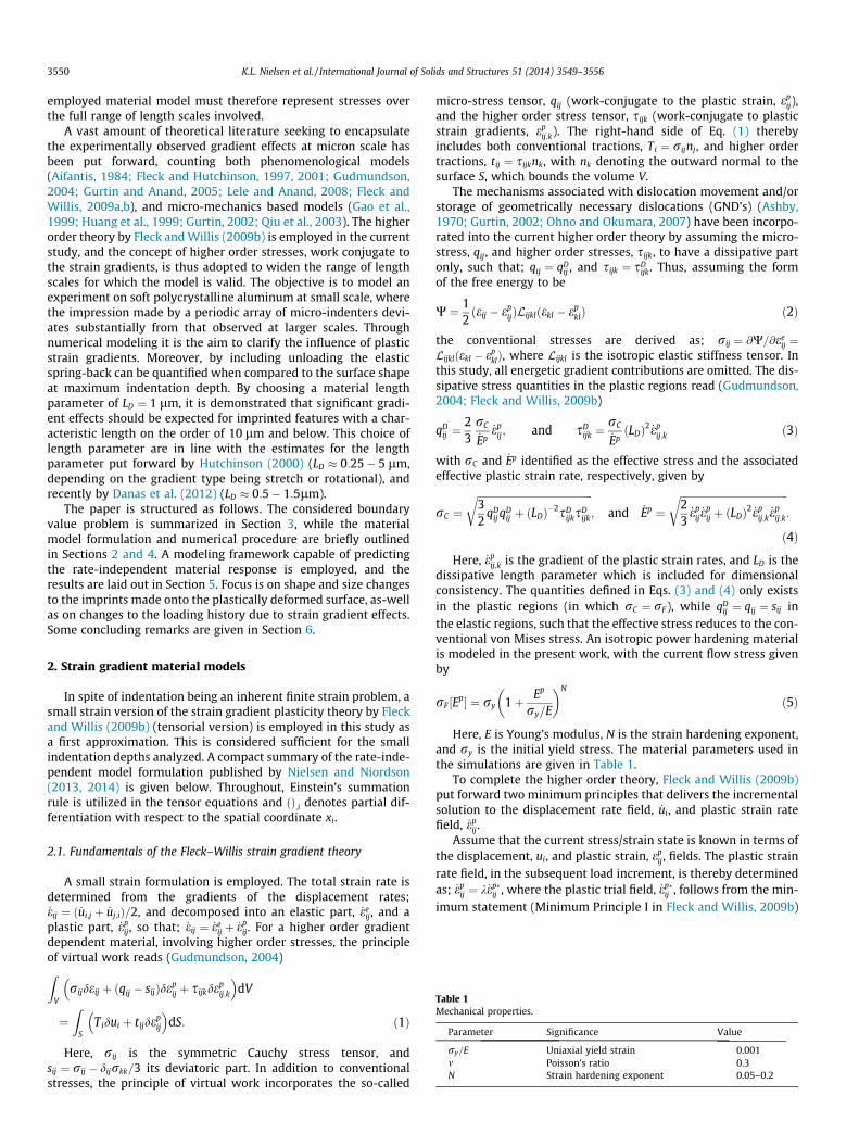
Punch response curves are shown in Fig. 2 in terms of the meancontact pressure under the punch as a function of indentationdepth, D, normalized by the half sheet thickness, H. Results areshown for a fixed ratio of channel width to indenter distance ofb=W ¼ 0:3, and material parameters chosen according to Table 1.An intermediate strain hardening exponent is chosen (N ¼ 0:1)
Fig. 2. Punch response curves displaying both loading and unloading of theindenter. Results are shown for LD=W ¼ ½0:03;0:1;0:3�, for the four boundaryconfigurations at the indenter interface; Case A ( _ep
ij ¼ 0; _u1 ¼ 0), Case B( _ep
ij ¼ 0; T1 ¼ 0), Case C (tij ¼ 0; _u1 ¼ 0), and Case D (tij ¼ 0; T1 ¼ 0). Here,N ¼ 0:1; b=W ¼ 0:3, and H=W ¼ 0:5.
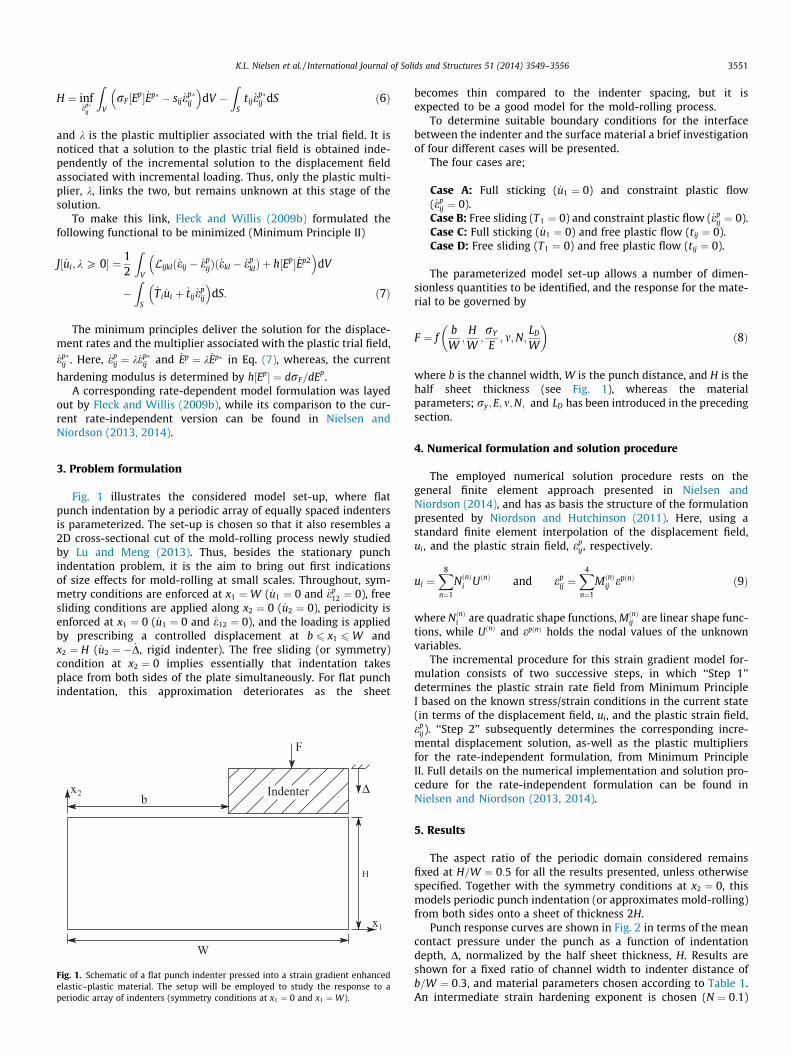
Fig. 3. Punch response curves showing the effect of conventional strain hardeningand hardening owing to plastic strain gradients. Results are shown forLD=W ¼ ½0:03;0:3�;N ¼ ½0:05;0:1;0:2�, and b=W ¼ 0:3 (Case A boundary conditions,and H=W ¼ 0:5).
3552 K.L. Nielsen et al. / International Journal of Solids and Structures 51 (2014) 3549–3556
along with three different material length parameters,LD=W ¼ ½0:03; 0:10;0:30�1, whereof the results for the smallestlength parameter closely resembles those of a conventional material.For each of the material length parameters, the four distinct bound-ary cases presented in Section 3 are considered, and results for allcombinations of full/no friction and full/no constraint on the plasticflow at the punch interfaces are brought out in Fig. 2. It is seen thatwhile the full constraint conditions (Case A) leads to the stiffestresponse, and the no constraint conditions (Case D) leads to the soft-est response, a full constraint on only one of the two fields (either _u1
or _epij) yields a similar response that lie in between the two extremes.
Furthermore, the results show that a significant size effect exists forthe periodic punch problem in agreement with the findings by Guhaet al. (2013a,b).
Throughout this work, all punch response curves are shown forboth loading and unloading of the indenter (thus until the indenterhas been completely retreated). It is clear that, initially unloadingtakes place along the same slope as that found at initial contact.However, as the contact area decreases while the indenter isretreated, the slope decreases; an effect most clearly seen for thelarger values of LD=W . It has been noticed that the indenter firstlooses contact with the deformed surface near the center of thechannel ðx1 ¼WÞ, whereafter this detached region spreads andeventually reaches the corners of the indenter at x1 ¼ b.
In the following studies only Case A (full friction and constraintplastic flow) for the interface condition at the punch is considered,as this gives raise to the highest peak load (though only small dif-ferences are predicted between Cases A–D).
The effect of conventional material hardening is presented inFig. 3, where results for N ¼ ½0:05;0:10;0:20� are shown for twovalues of the material length parameter, LD=W ¼ ½0:03;0:30�. Whileconventional hardening clearly influences the response, it is obvi-ous that gradient hardening dominates, and even the case withlow conventional hardening (N ¼ 0:05) exhibits very strong hard-ening due to strain gradients – in particularly for LD=W ¼ 0:3.
1 Employing the present Fleck–Willis model framework, the numerics becomeunstable for LD ! 0. It was found that LD=W ¼ 0:03 comes fairly close to that limit forthe current set-up.
The channel shape, in terms of the outline of the deformed topsurface, is presented in Figs. 4 and 5 upon complete removal of thepunch after indentation. Results are shown for three differentlength parameters, LD=W ¼ ½0:03;0:1;0:3�, and for two ratio ofchannel width to indenter spacing, b=W ¼ ½0:3;0:8�. For a lengthparameter that yields results close to the conventional limit(LD=W ¼ 0:03), a flat channel is produced with a ridge rising shar-ply where the indenter corners were in contact. This is seen forboth the narrow feature (b=W ¼ 0:3, compare Figs. 4a, c, and e),and the wider feature (b=W ¼ 0:8, compare Figs. 4b, d, and f). How-ever, when the material length parameter increases relative to theother geometric dimensions (or equivalently; if the scale of thegeometric parameters become relative smaller), these distinctdetails are lost as the channel become less flat by the ridge risingless sharply after unloading (see Fig. 4). This size effect on theshape of the channel, and the imprinted feature, is the focus of thisstudy as it complicates the process of making an accurate imprintthat match the indenter counterpart.
To quantify the size effects on the imprinted feature, a parame-terized model of the topology is set-up in Fig. 6. A target surface ofwidth ‘‘b’’ (according to Fig. 1) is here constructed so that itmatches the area underneath the curve that outlines the predictedsurface. Thus, the two surfaces will coincide in case of a perfectmatch (a ¼ b ¼ 1), whereas differences between the imprinted fea-ture and the target surface can be quantified by four key measures;(i) the channel depth, d�, (ii) the maximum width at average height,b, (iii) the deviation from the average height, a, and (iv) the inte-grated mismatch between the two curves, calculated as;Error =
RW0 jydef : � ytargetjdx=ADeformed
2. The evolution of the fourparameters is shown in Figs. 7–10 for fixed length parameters, andvarious values of the ratio of channel width to indenter spacings,b=W , and sheet thicknesses H=W .
For fixed sheet thickness and indenter displacement,(H=W ¼ 0:5 and D0=H ¼ 0:02), the ratio of channel width andindenter spacing, b=W , clearly influences on the shape of theimprinted feature, which in turn is affected by the length
2 Here, ydef : and ytarget are the curve describing the predicted and target imprint,respectively, and ADeformed is the area underneath the curves. An example is shown inFig. 6.
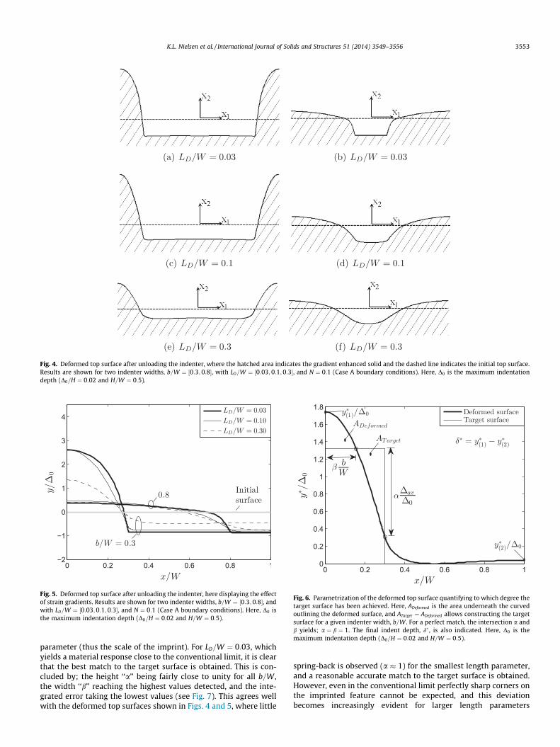
Fig. 4. Deformed top surface after unloading the indenter, where the hatched area indicates the gradient enhanced solid and the dashed line indicates the initial top surface.Results are shown for two indenter widths, b=W ¼ ½0:3;0:8�, with LD=W ¼ ½0:03;0:1;0:3�, and N ¼ 0:1 (Case A boundary conditions). Here, D0 is the maximum indentationdepth (D0=H ¼ 0:02 and H=W ¼ 0:5).
Fig. 5. Deformed top surface after unloading the indenter, here displaying the effectof strain gradients. Results are shown for two indenter widths, b=W ¼ ½0:3;0:8�, andwith LD=W ¼ ½0:03;0:1;0:3�, and N ¼ 0:1 (Case A boundary conditions). Here, D0 isthe maximum indentation depth (D0=H ¼ 0:02 and H=W ¼ 0:5).
Fig. 6. Parametrization of the deformed top surface quantifying to which degree thetarget surface has been achieved. Here, ADeformed is the area underneath the curvedoutlining the deformed surface, and ATarget ¼ ADeformed allows constructing the targetsurface for a given indenter width, b=W . For a perfect match, the intersection a andb yields; a ¼ b ¼ 1. The final indent depth, d� , is also indicated. Here, D0 is themaximum indentation depth (D0=H ¼ 0:02 and H=W ¼ 0:5).
K.L. Nielsen et al. / International Journal of Solids and Structures 51 (2014) 3549–3556 3553
parameter (thus the scale of the imprint). For LD=W ¼ 0:03, whichyields a material response close to the conventional limit, it is clearthat the best match to the target surface is obtained. This is con-cluded by; the height ‘‘a’’ being fairly close to unity for all b=W ,the width ‘‘b’’ reaching the highest values detected, and the inte-grated error taking the lowest values (see Fig. 7). This agrees wellwith the deformed top surfaces shown in Figs. 4 and 5, where little
spring-back is observed (a � 1) for the smallest length parameter,and a reasonable accurate match to the target surface is obtained.However, even in the conventional limit perfectly sharp corners onthe imprinted feature cannot be expected, and this deviationbecomes increasingly evident for larger length parameters
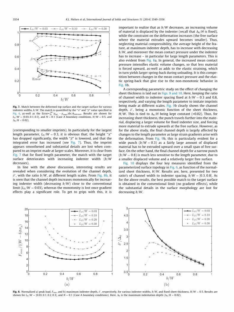
Fig. 7. Match between the deformed top surface and the target surface for variousindenter widths, b=W . The match is quantified by the ‘‘a’’ and ‘‘b’’ value specified inFig. 6, as-well as the Error=
RW0 jydef : � ytarget jdx=ADeformed . Results are shown for
LD=W ¼ ½0:03;0:1;0:3�, and N ¼ 0:1 (Case A boundary conditions, H=W ¼ 0:5, andD0=H ¼ 0:02).
3554 K.L. Nielsen et al. / International Journal of Solids and Structures 51 (2014) 3549–3556
(corresponding to smaller imprints). In particularly for the largestlength parameter, LD=W ¼ 0:3, it is obvious that; the height ‘‘a’’has dropped significantly, the width ‘‘b’’ is lowered, and that theintegrated error has increased (see Fig. 7). Thus, the imprintappears smoothened and substantial details are lost when com-pared to an imprint made at larger scales. Moreover, it is clear fromFig. 7 that for fixed length parameter, the match with the targetsurface deteriorates with increasing indenter width (b=Wdecreases).
In line with the above discussion, interesting results arerevealed when considering the evolution of the channel depth,d�, with the ratio b=W , at different length scales. From Fig. 8b, itis seen that the channel depth increases monotonically for increas-ing indenter width (decreasing b=W) close to the conventionallimit (LD=W ¼ 0:03), whereas the monotonity is lost once gradienteffects play a significant role. To get to grips with this, it is
Fig. 8. Normalized a) peak load, Fmax , and b) maximum indenter depth, d� , respectively,shown for LD=W ¼ ½0:03;0:1;0:2;0:3�, and N ¼ 0:1 (Case A boundary conditions). Here, D
important to realize that as b=W decreases, an increasing volumeof material is displaced by the indenter (recall that D0=H is fixed),while the constraint on the deformation increases (the free surfacewhere the material extrudes upward becomes smaller). Thus,neglecting material compressibility, the average height of the fea-ture, at maximum indenter depth, has to increase with decreasingb=W , and moreover the mean contact pressure under the indenterhas to increase – in particular for large length parameters. This isalso evident from Fig. 8a. In general, the increased mean contactpressure intensifies elastic volume changes, so that less materialis forced upward, as-well as adds to the elastic straining, whichin turn yields larger spring-back during unloading. It is this compe-tition between changes in the mean contact pressure and the elas-tic spring-back that give rise to the non-monotonic behavior inFig. 8b.
A corresponding parametric study on the effect of changing thesheet thickness is laid out in Figs. 9 and 10. Here, keeping the ratioof channel width to indenter spacing fixed at b=W ¼ 0:3 and 0.8,respectively, and varying the length parameter to imitate imprintsbeing made at different scales. Fig. 9b clearly shows the channeldepth, d�, being a monotonic function of the sheet thickness,H=W . This is tied to D0=H being kept constant (=0.02). Thus, forincreasing sheet thickness, the punch travels further into the mate-rial, displacing a larger volume for fixed indenter size, and forcingmore material to extrude upwards at the free surface. However, asfor the above study, the final channel depth is largely affected bychanges to the length parameter as large strain gradients arise withthe deformation. From Fig. 9b, this is particularly evident for awide punch (b=W ¼ 0:3) as a fairly large amount of displacedmaterial has to be extruded upward over a small span of free sur-face. On the other hand, the final channel depth for a narrow punch(b=W ¼ 0:8) is much less sensitive to the length parameter, due toa smaller displaced volume and a relatively larger free surface.
Fig. 10 displays the four key measures identified from theparameterized surface topology in Fig. 6, as function of the normal-ized sheet thickness, H=W . Results are, here, presented for tworatio’s of channel width to indenter spacing, b=W ¼ ½0:3;0:8�. Asfor the above results, the best possible match to the target surfaceis obtained in the conventional limit (no gradient effects), whilethe substantial details in the surface morphology are lost fordecreasing b=W .
for various indenter widths, b=W , and fixed sheet thickness, H=W ¼ 0:5. Results are0 is the maximum indentation depth (D0=H ¼ 0:02).
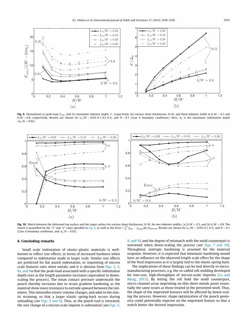
Fig. 9. Normalized (a) peak load, Fmax , and (b) maximum indenter depth, d� , respectively, for various sheet thicknesses, H=W , and fixed indenter width at b=W ¼ 0:3 andb=W ¼ 0:8, respectively. Results are shown for LD=W ¼ ½0:03;0:1;0:2;0:3�, and N ¼ 0:1 (Case A boundary conditions). Here, D0 is the maximum indentation depth(D0=H ¼ 0:02).
Fig. 10. Match between the deformed top surface and the target surface for various sheet thicknesses, H=W , for two indenter widths; (a) b=W ¼ 0:3, and (b) b=W ¼ 0:8. Thematch is quantified by the ‘‘a’’ and ‘‘b’’ value specified in Fig. 6, as-well as the Error =
RW0 jydef : � ytarget jdx=ADeformed . Results are shown for LD=W ¼ ½0:03;0:1;0:3�, and N ¼ 0:1
(Case A boundary conditions, and D0=H ¼ 0:02).
K.L. Nielsen et al. / International Journal of Solids and Structures 51 (2014) 3549–3556 3555
6. Concluding remarks
Small scale indentation of elastic–plastic materials is well-known to reflect size effects, in terms of increased hardness whencompared to indentation made at larger scale. Similar size effectsare predicted for flat punch indentation, or imprinting of micronscale features onto sheet metals, and it is obvious from Figs. 2, 3,8a, and 9a that the peak-load associated with a specific indentationdepth rises as the length parameter increases (equivalent to down-scaling the process). The mean contact pressure underneath thepunch thereby increases due to strain gradient hardening as thematerial show more resistance to extrude upward between the ind-enters. This intensifies elastic volume changes, and adds to the elas-tic straining, so that a larger elastic spring-back occurs duringunloading (see Figs. 5 and 6). Thus, as the punch tool is retreated,the size change of a micron scale imprint is substantial (see Figs. 5,
8, and 9), and the degree of mismatch with the mold counterpart isworsened when down-scaling the process (see Figs. 7 and 10).Throughout, isotropic hardening is assumed for the materialresponse. However, it is expected that kinematic hardening wouldhave an influence on the observed length scale effect for the shapeof the final impression as it is largely tied to the elastic spring back.
The implications of these findings can be tied directly to micro-manufacturing processes, e.g. the so-called roll-molding developedfor low-cost, high-throughput of micron-scale imprints (Lu andMeng, 2013). By letting the roll hold the mold counterpart,micro-channel array imprinting on thin sheet metals poses essen-tially the same issues as those treated in the presented work. Thus,the shape of the imprinted features will be affected by down-scal-ing the process. However, shape optimization of the punch geom-etry could potentially improve on the imprinted feature so that amatch better the desired impression.

3556 K.L. Nielsen et al. / International Journal of Solids and Structures 51 (2014) 3549–3556
Acknowledgements
K.L. Nielsen and C.F. Niordson are financially supported by TheDanish Council for Independent Research under the research careerprogramme Sapere Aude in the project ‘‘Higher Order Theories inSolid Mechanics’’.
References
Aifantis, E., 1984. On the microstructural origin of certain inelastic models. J. Eng.Mater. Technol. 106, 326–330.
Ashby, M., 1970. The deformation of plastically non-homogeneous alloys. Philos.Mag. 21, 399–424.
Danas, K., Deshpande, V., Fleck, N., 2012. Size effects in the conical indentation of anelasto-plastic solid. J. Mech. Phys. Solids 60, 1605–1625.
Fleck, N., Hutchinson, J., 1997. Strain gradient plasticity. Adv. Appl. Mech. 33,295–361.
Fleck, N., Hutchinson, J., 2001. A reformulation of strain gradient plasticity. J. Mech.Phys. Solids 49, 2245–2271.
Fleck, N., Willis, J., 2009a. A mathematical basis for strain-gradient plasticity theory.Part I: scalar plastic multiplier. J. Mech. Phys. Solids 57, 161–177.
Fleck, N., Willis, J., 2009b. A mathematical basis for strain-gradient plasticity theory.Part II: tensorial plastic multiplier. J. Mech. Phys. Solids 57, 1045–1057.
Gao, H., Huang, Y., Nix, W., Hutchinson, J., 1999. Mechanism-based strain gradientplasticity I: analysis. J. Mech. Phys. Solids 47, 1239–1263.
Gudmundson, P., 2004. A unified treatment of strain gradient plasticity. J. Mech.Phys. Solids 52, 1379–1506.
Guha, S., Sangal, S., Basu, S., 2013a. Finite element studies on indentation size effectusing a higher order strain gradient theory. Int. J. Solids Struct. 50, 863–875.
Guha, S., Sangal, S., Basu, S., 2013b. Numerical investigations of flat punch moldingusing a higher order strain gradient plasticity theory. Int. J. Mater. Forum.
Gurtin, M., 2002. A gradient theory of single-crystal viscoplasticity that accounts forgeometrically necessary dislocations. J. Mech. Phys. Solids 50, 5–32.
Gurtin, M., Anand, L., 2005. A theory of strain-gradient plasticity for isotropic,plastically irrotational materials. Part I: small deformations. J. Mech. Phys.Solids 53, 1624–1649.
Hill, R., 1950. The Mathematical Theory of Plasticity. Oxford University Press, GreatCladeron Street, Oxford, New York.
Huang, Y., Gao, H., Nix, W., Hutchinson, J., 1999. Mechanism-based strain gradientplasticity II: analysis. J. Mech. Phys. Solids 48, 99–128.
Hutchinson, J., 2000. Plasticity at the micron scale. Int. J. Solids Struct. 37, 225–238.Lele, S., Anand, L., 2008. A small-deformation strain-gradient theory for isotropic
viscoplastic materials. Philos. Mag. 88, 3655–3689.Lu, B., Meng, W., 2013. Roll molding of microchannel arrays on Al and Cu sheet
metals: a method for high-throughput manufacturing. J. Micro Nano Manuf.Nepershin, R., 2002. Indentation of a flat punch into a rigid-plastic half space.
J. Appl. Math. Mech. 66, 135–140.Nielsen, K., Niordson, C., 2013. A 2D finite element implementation of the Fleck–
Willis strain-gradient flow theory. Eur. J. Mech. A/Solids 41, 134–142.Nielsen, K., Niordson, C., 2014. A numerical basis for strain-gradient plasticity
theory: rate-independent and rate-dependent formulations. J. Mech. Phys.Solids 63, 113–127.
Niordson, C., Hutchinson, J., 2011. Basic strain gradient plasticity theories withapplication to constrained film deformation. J. Mech. Mater. Struct. 6, 395–416.
Ohno, N., Okumara, D., 2007. Higher-order stress and grain size effects due toself-energy of geometrically necessary dislocations. J. Mech. Phys. Solids 55,1879–1898.
Qiu, X., Huang, Y., Wei, Y., Gao, H., Hwang, K., 2003. The flow theory of mechanism-based strain gradient plasticity. Mech. Mater. 35, 245–258.


![UNCLASSI]I ED A D 402! 2I 2 - dtic.milI ED A D 402! 2I 2 ... IN CONTINUUM MECHANICS by M. E. Gurtin SiA APR? TIv 25 ... M. E. Gurtin Brown riUniversity 1. Introduction](https://img.pdfslide.us/doc/110x75/5af062f87f8b9ac57a8e871b/unclassii-ed-a-d-402-2i-2-dtic-i-ed-a-d-402-2i-2-in-continuum-mechanics.jpg)

![An Introduction to Continuum Mechanics[M. E. Gurtin][Ed-1981]](https://img.pdfslide.us/doc/110x75/55cf9802550346d03394fb35/an-introduction-to-continuum-mechanicsm-e-gurtined-1981.jpg)