Embed Size (px)
Citation preview

CITY OF ELIZABETHTON
STORMWATER GUIDANCE MANUAL
MAY 2012
MAY 2012
CITY OF ELIZABETHTON STORMWATER GUIDANCE MANUAL
TABLE OF CONTENTS SECTION PAGE CHAPTER 1 - PURPOSE AND GUIDANCE OVERVIEW 1.1 GENERAL OVERVIEW………………………………………………….………1 CHAPTER 2 - HYDROLOGIC/HYDRAULIC STUDIES 2.1 GENERAL OVERVIEW…………………………………………………….……1 2.2 REQUIRED DATA…………………………………………………….….………1 2.3 HYDROLOGY……………………………………………………………….……3 2.4 APPROVED METHODOLOGY…………………………………………….……3 2.5 SCS TR-55, TR-20 METHOD……………………………………………….……4 2.6 RATIONAL METHOD………………………………………………………..…. 5 CHAPTER 3 - DESIGN STANDARDS 3.1 GENERAL OVERVIEW……………………………………………………….….1 3.2 STORMWATER DETENTION FACILITIES……………………………….……2 3.3 STORM SEWER PIPES……………………………………………………….…..3 3.4 OPEN CHANNELS…………………………………………………………….….5 CHAPTER 4 - STORMWATER REPORT CONTENTS 4.1 GENERAL OVERVIEW……………………………………………………….…..1 4.2 STORMWATER ANALYSIS REPORT……………………………………….…..1 4.3 FINAL PLANS………………………………………………………………….…..2

CHAPTER 1 PURPOSE AND GUIDANCE OVERVIEW
1.1 General Overview The purpose of this Stormwater Guidance Manual is to outline the general guidelines and policies of the City of the Elizabethton with respect to stormwater management for new and redevelopment projects within the limits of the City of Elizabethton. This manual provides guidance for the design of storm sewer piping systems, open channels and stormwater detention facilities. This manual provides standards to assure quality in the design and construction of stormwater infrastructure and facilities and provides standard criteria for design assumptions and general methods of design. This manual also summarizes the calculations and design details required for the City’s review and approval as a part of the site plan submittals. This manual includes requirements for the hydrologic/hydraulic studies that are typically required for a project design, however more comprehensive methods of analysis and design may be required for unusual conditions not specifically covered in this manual or where otherwise appropriate from an engineering standpoint to assure public safety and quality in infrastructure design and construction. The designer is encouraged to meet with the City during the initial design of the project to discuss the proposed method of stormwater management and site specific issues. The City’s Stormwater Coordinator can be contacted at (423) 547-6240. This manual serves as a supplement to the City’s Permanent Water Quality Ordinance, Erosion and Sediment Control Ordinance and Illicit Discharge Ordinance. These ordinances are described in detail on the City’s website at http://www.elizabethton.org/government/stormwater/
1

CHAPTER 2 HYDROLOGIC/HYDRAULIC STUDIES
2.1 General Overview The definition of hydrologic and hydraulic studies as used in this manual is the compilation and analysis of all pertinent information on which the design was based. This includes maps, field survey information, source references, photographs, engineering calculations and analysis, and any other pertinent data, such as documented drainage problems or flooding issues. As a part of the site design process, hydrologic and/or hydraulic studies shall be conducted to:
determine the effects of the proposed development on the adjoining upstream and downstream drainage systems,
establish the existing and post-development peak discharge rates for
the required rainfall events,
ensure that structures will be protected from flooding during the 100-year rainfall event,
preserve the boundaries of existing watersheds, and
design a stormwater management plan for the proposed development.
2.2 Required Data The computation of the stormwater flows must take into account the land use, soil types, project area, rainfall intensity, and land slopes. Therefore it is essential that the study be based on accurate information. The following data shall be obtained to support the hydrologic and/or hydraulic studies:
An existing site survey which includes contours on 2’ increments (except in exceptionally flat areas which require 1’ contour increments).
1
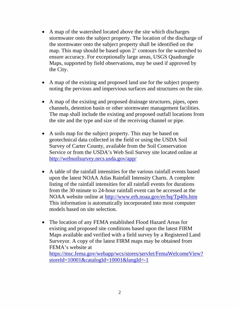
A map of the watershed located above the site which discharges stormwater onto the subject property. The location of the discharge of the stormwater onto the subject property shall be identified on the map. This map should be based upon 2’ contours for the watershed to ensure accuracy. For exceptionally large areas, USGS Quadrangle Maps, supported by field observations, may be used if approved by the City.
A map of the existing and proposed land use for the subject property
noting the pervious and impervious surfaces and structures on the site.
A map of the existing and proposed drainage structures, pipes, open channels, detention basin or other stormwater management facilities. The map shall include the existing and proposed outfall locations from the site and the type and size of the receiving channel or pipe.
A soils map for the subject property. This may be based on
geotechnical data collected in the field or using the USDA Soil Survey of Carter County, available from the Soil Conservation Service or from the USDA’s Web Soil Survey site located online at http://websoilsurvey.nrcs.usda.gov/app/
A table of the rainfall intensities for the various rainfall events based
upon the latest NOAA Atlas Rainfall Intensity Charts. A complete listing of the rainfall intensities for all rainfall events for durations from the 30 minute to 24-hour rainfall event can be accessed at the NOAA website online at http://www.erh.noaa.gov/er/hq/Tp40s.htm This information is automatically incorporated into most computer models based on site selection.
The location of any FEMA established Flood Hazard Areas for
existing and proposed site conditions based upon the latest FIRM Maps available and verified with a field survey by a Registered Land Surveyor. A copy of the latest FIRM maps may be obtained from FEMA’s website at https://msc.fema.gov/webapp/wcs/stores/servlet/FemaWelcomeView?storeId=10001&catalogId=10001&langId=-1
2
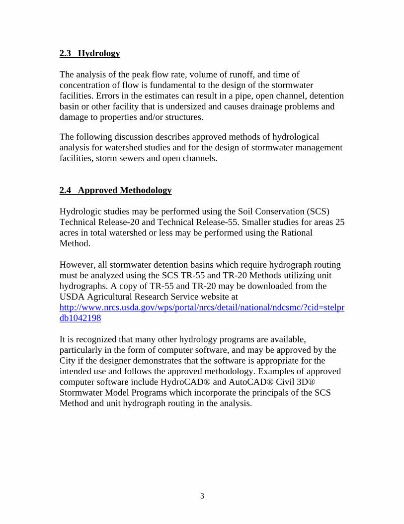
2.3 Hydrology The analysis of the peak flow rate, volume of runoff, and time of concentration of flow is fundamental to the design of the stormwater facilities. Errors in the estimates can result in a pipe, open channel, detention basin or other facility that is undersized and causes drainage problems and damage to properties and/or structures. The following discussion describes approved methods of hydrological analysis for watershed studies and for the design of stormwater management facilities, storm sewers and open channels. 2.4 Approved Methodology Hydrologic studies may be performed using the Soil Conservation (SCS) Technical Release-20 and Technical Release-55. Smaller studies for areas 25 acres in total watershed or less may be performed using the Rational Method. However, all stormwater detention basins which require hydrograph routing must be analyzed using the SCS TR-55 and TR-20 Methods utilizing unit hydrographs. A copy of TR-55 and TR-20 may be downloaded from the USDA Agricultural Research Service website at http://www.nrcs.usda.gov/wps/portal/nrcs/detail/national/ndcsmc/?cid=stelprdb1042198 It is recognized that many other hydrology programs are available, particularly in the form of computer software, and may be approved by the City if the designer demonstrates that the software is appropriate for the intended use and follows the approved methodology. Examples of approved computer software include HydroCAD® and AutoCAD® Civil 3D® Stormwater Model Programs which incorporate the principals of the SCS Method and unit hydrograph routing in the analysis.
3
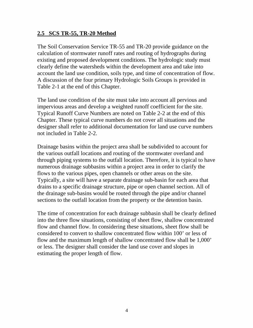
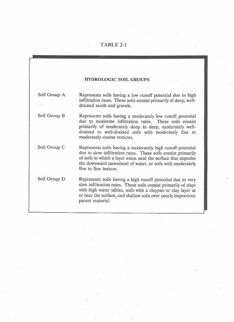
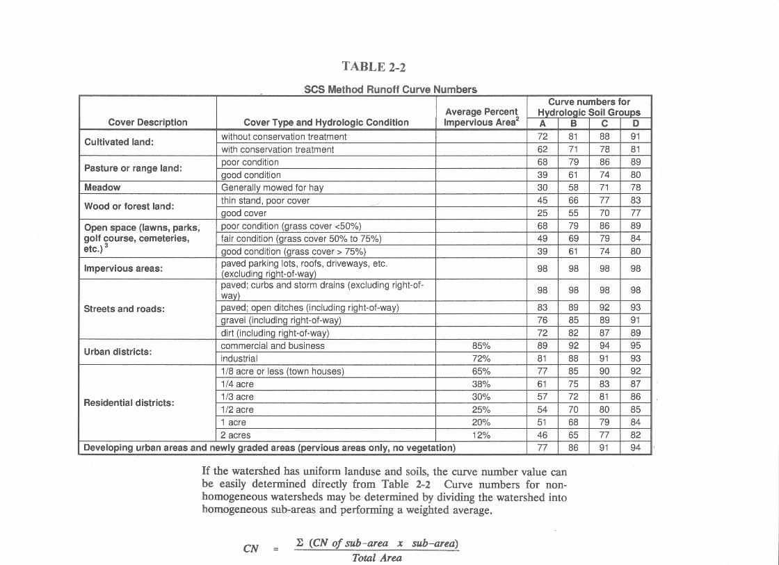
2.5 SCS TR-55, TR-20 Method The Soil Conservation Service TR-55 and TR-20 provide guidance on the calculation of stormwater runoff rates and routing of hydrographs during existing and proposed development conditions. The hydrologic study must clearly define the watersheds within the development area and take into account the land use condition, soils type, and time of concentration of flow. A discussion of the four primary Hydrologic Soils Groups is provided in Table 2-1 at the end of this Chapter. The land use condition of the site must take into account all pervious and impervious areas and develop a weighted runoff coefficient for the site. Typical Runoff Curve Numbers are noted on Table 2-2 at the end of this Chapter. These typical curve numbers do not cover all situations and the designer shall refer to additional documentation for land use curve numbers not included in Table 2-2. Drainage basins within the project area shall be subdivided to account for the various outfall locations and routing of the stormwater overland and through piping systems to the outfall location. Therefore, it is typical to have numerous drainage subbasins within a project area in order to clarify the flows to the various pipes, open channels or other areas on the site. Typically, a site will have a separate drainage sub-basin for each area that drains to a specific drainage structure, pipe or open channel section. All of the drainage sub-basins would be routed through the pipe and/or channel sections to the outfall location from the property or the detention basin. The time of concentration for each drainage subbasin shall be clearly defined into the three flow situations, consisting of sheet flow, shallow concentrated flow and channel flow. In considering these situations, sheet flow shall be considered to convert to shallow concentrated flow within 100’ or less of flow and the maximum length of shallow concentrated flow shall be 1,000’ or less. The designer shall consider the land use cover and slopes in estimating the proper length of flow.
4
5
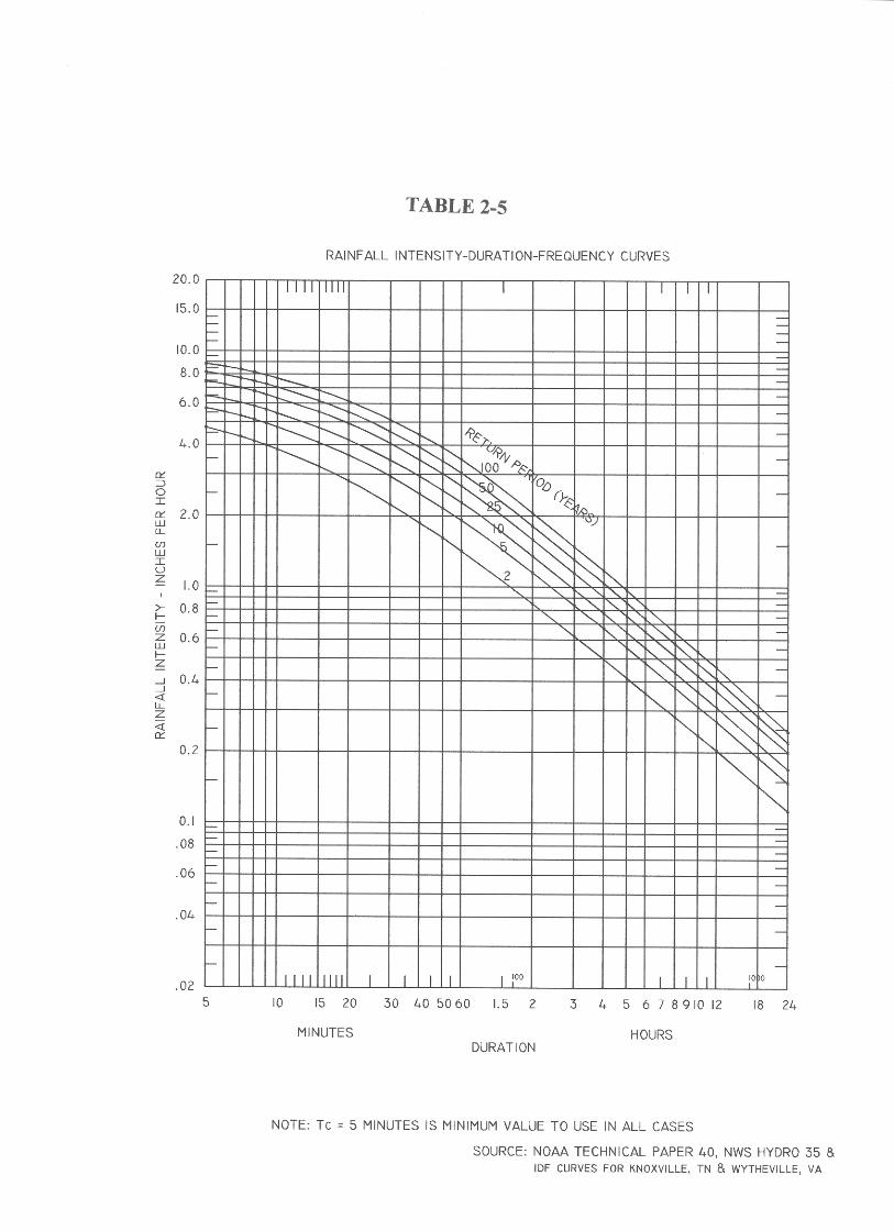
2.6 Rational Method The Rational Method equation may be used for drainage areas less than or equal to 25 acres to determine the sizing of storm sewers or open channels. The Rational Method equation shall not be used for the sizing of any stormwater detention facilities. Q = CIA where: Q = peak flow in cubic feet per second C = 0.95 for impervious areas 0.20 for pervious areas A = drainage area I = rainfall intensity The runoff coefficient, C, shall be based upon the land use of the entire site. Typical values of the runoff coefficient for the Rational Method are noted on Tables 2-3 and 2-4 at the end of this Chapter. A weighted C factor shall be determined for sites that have multiple land use covers. The time of concentration shall be determined using the method described in SCS TR #55. The minimum recommended time of concentration is 5 minutes. The rainfall intensity shall be determined using the time of concentration and the I-D-F curve for Carter County, TN. A copy of this I-D-F curve is shown on Table 2-5 at the end of this Chapter.


CHAPTER 3 DESIGN STANDARDS
3.1 General Overview The following minimum requirements shall pertain to all new and redevelopment projects:
Post-development peak discharge rates for the 2 through 10-year, 24-hour rainfall events shall not exceed the peak discharge rates for existing site conditions. In the event that there are inadequate receiving facilities downgradient of the property or existing drainage problems, the post-development peak discharge rate shall be controlled for the 2 through 100-year, 24-hour rainfall events. The designer shall contact the City to assist in identifying locations that may require additional detention.
The site shall accommodate the flow of stormwater onto the subject
property from upland areas and control the stormwater during the 100-year, 24-hour rainfall event.
The site shall discharge stormwater to an appropriate receiving
channel in a similar manner to existing conditions. The design velocity at the discharge location shall be controlled to protect downstream channels and properties from erosion. Designers are encouraged to discharge stormwater a minimum of 15’ from the property line when discharging to a sheet flow condition or open channel and to use rip-rap or level spreaders as needed to convert concentrated flow to sheet flow and control velocities.
The site design shall elevate all proposed structures a minimum of 1’
above the stormwater elevations resulting from the 100-year, 24-hour rainfall event.
Storm sewer pipes serving the proposed development shall be
designed to flow under gravity (no pressure) during the 10-year, 24-hour rainfall event and to not surcharge out of any drainage structure during the 25-year, 24-hour rainfall event. Storm sewer pipes installed
1
2
to collect and route off-site drainage through the subject property shall be designed to accommodate the flows generated during the 100-year, 24-hour rainfall event without increasing backup onto the adjoining property. The minimum pipe size allowed is 15” in diameter unless the pipe is serving a roof downdrain.
Open channels shall be designed with the capacity to accommodate
the flows generated by the 10-year rainfall event using the Manning Equation. The lining of the open channels shall be designed to prevent erosion for the flows generated by the 2-year rainfall event.
3.2 Stormwater Detention Facilites Stormwater detention facilities may be above-ground or underground systems as determined by the designer. All detention systems must provide adequate control and discharge of the peak discharge rates generated by the 2 through 10-year, 24-hour rainfall events to existing levels or below. As discussed earlier, additional stormwater detention up to the 100-year event may be required by the City. Above-ground detention basins shall be graded to provide positive drainage to the outlet structure. In no case shall the bottom of the detention basin have less than a 1% slope. The sides of the detention basin shall not exceed 2:1 and shall provide for maintenance access to the basin standpipe. Above-ground detention basins shall be no higher than 9’ in height and shall have a top of berm width of at least 5’. The detention basin side slopes and berm shall be compacted to 98% standard proctor. The detention basin shall drain via a reinforced concrete standpipe or concrete outlet structure with orifices provided to control the discharge. The bottom opening on the standpipe or outlet structure shall be protected from clogging by use of a debris rack or other approved device. A reinforced concrete pipe shall be used for the discharge pipe serving the basin. The outlet pipe shall discharge onto a rip-rap pad or concrete matting to control stormwater velocities. An anti-seep collar(s) shall be constructed on the outlet pipe in the center of the basin berm to discourage “piping” of the stormwater along the outer surface of the outlet pipe. Additional anti-seep collars may be required based upon the length of the outlet pipe and site

specific situations. These shall be addressed by the designer in the calculations and design. An overflow spillway shall be provided in the top of the basin berm. The overflow spillway shall have a minimum depth of 1’ and shall be stabilized according to the frequency of flow and expected stormwater velocities. The sides of a grassed spillway shall be no steeper than 2:1. The spillway shall direct any overflow from the basin to a natural outfall location. The basin shall be designed to accommodate the safe passage of stormwater over the spillway during the 100-year, 24-hour rainfall event. The basin standpipe shall have an anti-votex top to allow flows from larger rainfall events to flow into the standpipe. The top of the standpipe shall be located a minimum of 1’ below the overflow spillway. Underground detention facilities shall be provided in either concrete or HDPE watertight facilities and shall not allow for infiltration into the subsurface. The underground facility should allow for maintenance access at each end of the system or more often as appropriate and approved by the City. The underground detention facility shall control the discharge from the required rainfall events and make accommodation for bypass of the larger rainfall events, up to the 100-year rainfall event without surcharging out of the underground detention facility. Stormwater detention facilities shall incorporate water quality features, as applicable, and shall provide the Channel Protection discharge as described the City’s Permanent Water Quality Ordinance. All detention facilities shall have a plan of inspection and maintenance provided with the submitted plans and a note regarding the ownership of the facility and responsibility for maintenance.
3.3 Storm Sewer Pipes The sizing of a storm pipe may be performed using the Manning Formula. Storm sewer pipes serving the proposed development shall be designed to flow under gravity (no pressure) during the 10-year, 24-hour rainfall event
3

and to not surcharge out of any drainage structure during the 25-year, 24-hour rainfall event. Storm sewer pipes serving the roof downdrains of structures shall be sized to accommodate the peak discharge rate generated by the 100-year, 24-hour rainfall event. The minimum size of a pipe shall be 15” in diameter for maintenance purposes. Storm sewer pipes shall be reinforced concrete or HDPE and shall have rubber gaskets for watertightness. Pipes shall be connected to manholes or other drainage structures utilizing flexible rubber gaskets for watertightness. Access to the piping system shall be provided every 400’ or less via manholes or other approved structures. The minimum cover over a storm pipe is 3’ from finished grade to the top of the pipe, unless severally limited by site specific circumstances. If less than 3’ of cover will be provided over the pipe, the designer must justify the structural support of the pipe. Piping systems used to collect off-site drainage flowing onto the property shall be provided within a 20’ wide recorded easement so that upgradient drainage is not blocked in the future and access to the storm piping system is available to the City. The piping system carrying the flow from the off-site areas shall be designed to not increase backup onto the adjoining property during the 100-year, 24-hour rainfall event.
Storm pipe calculations shall be provided for each section of storm pipe and shall include a drainage area map and the supporting hydrologic considerations. If the storm pipe system cannot route the 100-year flow to the detention basin or outfall location, then open channels or grading of the site must be designed to accomplish this without causing damage to any properties or structures. Stabilized outfall pads, such as rip-rap or concrete matting must be designed at the discharge ends of the storm pipes to minimize erosion to adjoining properties. Pipe bedding shall be in accordance with the manufacturer’s recommendations and industry standards. It is recommended that pipe bedding for any pipes located under existing or proposed paved areas be backfilled with compacted stone to subgrade elevations.
4

Pipe bedding for reinforced concrete pipe shall be compacted stone under the haunches of the pipe to the middle of the pipe. Pipe bedding for HDPE shall be compacted stone under the haunches of the pipe to a minimum of 1’ above the pipe, or as recommended by the manufacturer based on the pipe size and structural support requirement.
3.4 Open Channels Open channels include roadside channels and stormwater drainage channels with regular geometric cross-sections and lining of natural or synthetic materials to protect against erosion. Safety of the general public shall be an important consideration in the selection of cross-sectional geometry of constructed channels. The design of channels shall consider the frequency and type of maintenance expected and make allowances for access of maintenance equipment. In general, open channels shall be designed with the capacity to accommodate the flows generated by the 10-year rainfall event, 24-hour rainfall event. The calculations shall also note the depth of flow in the open channel during the 100-year, 24-hour rainfall event and discuss how this flow will be routed through the site if it exceeds the capacity of the open channel. The open channels may be designed using the Manning Equation, as shown below: Q = (1.49/n)AR2/3 S1/2 Where: Q = discharge, cfs n = Manning’s roughness coefficient A = cross-sectional area of flow, ft2 R = hydraulic radius = A/P, ft P = wetted perimeter, ft S = channel slope, ft/ft Select Manning’s n from Table 3-1 on the following page or from other verified sources
5

6
TABLE 3-1
MANNING’S n FOR CONSTRUCTED CHANNELS Lining Type Manning’s n Concrete……………………………………… 0.011 Stone Masonry……………………………….. 0.032 Rock Cut……………………………………... 0.035 6-inch D50 Riprap…………………………… 0.050 12-inch D50 Riprap………………………….. 0.060 Grass…………………………………………. 0.022 The lining of the open channels shall be designed to prevent erosion for the flows generated by the 2-year rainfall event. It is preferable that swales be designed to have non-erosive grassed linings, however, if velocities exceed that permissible for grass linings, then rip-rap, concrete or other stabilization measures must be provided and justified in the stormwater analysis report. A table noting the permissible velocities for a grassed line channel under various slope and grass type conditions is shown in Table 3-2 below:
TABLE 3-2
PERMISSIBLE VELOCITIES FOR GRASS-LINED CHANNELS Channel Slope Lining Permissible Velocity 0-5% Fescue or Kentucky Bluegrass 5 ft/sec 5-10% Fescue or Kentucky Bluegrass 4 ft/sec Greater than 10% Fescue or Kentucky Bluegrass 3 ft/sec Channel capacity and stabilization calculations shall be provided for each unique section of the open channel and shall include a drainage area map noting each of the drainage sub-basins and the supporting hydrologic considerations.

CHAPTER 4 STORMWATER REPORT CONTENTS
4.1 General Overview
The designer shall provide the City a complete analysis documentation of the on-site and off-site stormwater flows associated with the specific project and the method in which stormwater management will be addressed and the justification thereof. The primary purpose of providing good documentation is to define the design procedure that was used and decisions that were made to arrive at the final design. Documentation should be viewed as the record of reasonable and prudent design analysis based on the best available technology. 4.2 Stormwater Analysis Report The stormwater analysis report provided to the City shall provide a written narrative which summarizes:
the proposed project construction,
existing site conditions (including discussion of off-site drainage flowing onto the site and how stormwater currently discharges from the site),
proposed flow rates generated by the proposed development and the
method of collection and sizing of piping and/or swales and stormwater management facilities,
discussion and analysis of downgradient drainage systems receiving
the stormwater runoff from the subject property,
summary table(s) showing existing and post-development flows for the 2, 10, and 100-year, 24-hour rainfall events (using Unit Hydrographs routed through the detention system as applicable) for the site at each discharge location from the property.
1
Inspection and maintenance procedures for the stormwater facilities and any fencing or landscaping recommendations,
In addition, appendices shall be provided in the stormwater analysis report with the supporting hydrologic/hydraulic calculations:
a map of the various individual drainage sub-basins used in the stormwater analysis report with each sub-basin identified consistent with the analysis,
a printout of the design assumptions used and calculations for
each drainage sub-basin for the 2, 10 and 100-year, 24-hour rainfall events,
a printout of the pipe capacity calculations for each section of pipe
for the 10 and 25-year, 24-hour rainfall events,
a printout of the open channel calculations for each unique section of open channel for the 2, 10 and 100-year, 24-hour rainfall events, and
a copy of the outlet pad calculations for each storm pipe discharge
location.
4.3 Final Plans
Final design drawings shall be 24” x 36” in size. Plan view drawings shall be at a maximum scale of 1”=50’ with 2’ contours. The final design drawings shall include the following information:
a map of the existing site conditions noting the existing land use, cover conditions, and any storm pipe or open channel sections,
the location of all proposed construction including pervious and
impervious areas and structures with the proposed elevations indicated,
2

3
the location of all proposed drainage inlets and manholes, with the top and invert elevations of each structure and the details associated with the construction of the structures,
the location, size, type and slope of all proposed storm sewer
pipes including details for the bedding of the pipe,
the location and grading of all open channels and a typical section of each unique section of open channel indicating the channel geometry and stabilization measures,
the location and grading of any detention basins and details of the
detention basin standpipe or outlet structure, basin outlet pipe and anti-seep collar, basin anti-vortex top, overflow spillway, compaction requirements and any anti-clogging devices used on the lower orifices of the standpipe,
the location and type of any water quality facility and associated
easements as required by the City’s Permanent Water Quality Ordinance.