Embed Size (px)
Citation preview

Twin-Walled Corrugated Polypropylene Pipe and Fittings for Non-Pressure Applications
LIGHT WEIGHT
MATERIAL EFFICIENT
EASY TO HANDLE
COST EFFECTIVE TO INSTALL
CORROSION RESISTANT
ABRASION RESISTANT
CHEMICAL RESISTANT
LONG LIFE PRODUCT
SUPERIOR JOINT PERFORMANCE
stormprO™ & sewerprO™

stormprO™ & sewerprO™
intrODuCtiOn 1
BeneFits 2
installer 2
user 2
environment 2
prODuCt list 3
pipe 3
Fittings 4
prODuCt DAtA 7
manufacture 7
material properties 7
Chemical resistance 8
temperature 8
Weathering resistance 8
standards 8
pipe Dimensions 9
pipe lengths 10
Joint Details 10
DesiGn 11
Hydraulic Design 11
Choice of roughness Coefficients 12
structural Design 18
instAllAtiOn 19
General 19
Handling and storage 19
trench preparation 20
Jointing 21
Cutting of pipes 21
selection of embedment material 22
pipe laying 22
Connection to structures 22
leakage testing 23
Cut-ins AnD repAirs 24
Cut-ins 24
repairs 24
limitation of liability
This product catalogue has been compiled by Vinidex Pty Limited (“the Company”) to promote better understanding of the technical aspects of the Company’s products to assist users in obtaining from them the best possible performance. The product catalogue is supplied subject to acknowledgement of the following conditions:
1 The product catalogue is protected by copyright and may not be copied or reproduced in any form or by any means in whole or in part without prior consent in writing by the Company. 2 Product specifications, usage data and advisory information may change from time to time with advances in research and field experience. The Company reserves the right to make such changes at any time without further notice. 3 Correct usage of the Company’s products involves engineering judgements, which can not be properly made without full knowledge of all the conditions pertaining to each specific installation. The Company expressly disclaims all and any liability to any person whether supplied with this publication or not in respect of anything and all of the consequences of anything done or omitted to be done by any such person in reliance whether whole or part of the contents of this publication. 4 No offer to trade, nor any conditions of trading, are expressed or implied by the issue of content of this product catalogue. Nothing herein shall override the Company’s Condition of Sale, which may be obtained from the Registered Office or any Sales Office of the Company. 5 This product catalogue is and shall remain the property of the Company, and shall be surrendered on demand to the Company. 6 Information supplied in this product catalogue does not override a job specification, where such conflict arises; consult the authority supervising the job. © Copyright vinidex pty limited.

1
intrODuCtiOn
Vinidex StormPRO™ and SewerPRO™ pipes are twin-wall, corrugated polypropylene pipes for non-pressure applications, manufactured in accordance with AS/NZS 5065.
Utilising modern co-extrusion techniques, StormPRO™ and SewerPRO™ are manufactured with a smooth bore for optimum hydraulic performance and a corrugated outside wall for high stiffness to weight ratio.
By combining the strength and toughness of advanced polypropylene materials with the structured wall design, StormPRO™ and SewerPRO™ pipes provide an environmentally sensitive, cost-effective piping system for a multitude of sewerage and drainage applications in sizes ranging from 150mm to 900mm.
stormprO™ & sewerprO™

stormprO™ & sewerprO™
2
BeneFits
installer
• Light weight• Long lengths• Ease of handling• Less heavy equipment required• Hydraulic capacity• Structural integrity• Safety – less chance of injury• No chamfer required • Speed of installation• Ease of jointing• Less maintenance • Impact resistance – site handling• Cost savings in installation • No damage due to transport• Easy to cut • Ring cannot be dislodged
user
• Cost effective installation• Corrosion resistance• Abrasion resistance • Joint performance – leak tightness
and tree root resistance• Benefits of a flexible pipe
– structural integrity• Long life
environment
• Material efficient• Long life product• Joint performance • No exfiltration – no pollution• No infiltration – savings on
treatment costs due to lower volumes
• Recyclable at end of life

stormprO™ & sewerprO™
3
prODuCt list
There are two distinct product ranges which are readily identified by their colour.
The SN8 StormPRO™ pipes are intended for stormwater and general drainage applications and have a black coloured outside surface and a light grey inside surface.
pipe
stormprO™ polypropylene pipe – 6m length (sp – so)
nominal Diameter product Code product Description
150 29411 150mm SN8 StormPRO PP
225 29412 225mm SN8 StormPRO PP
300 29413 300mm SN8 StormPRO PP
375 29414 375mm SN8 StormPRO PP
450 29415 450mm SN8 StormPRO PP
525 29416 525mm SN8 StormPRO PP
600 29417 600mm SN8 StormPRO PP
750 29418 750mm SN8 StormPRO PP
900 29419 900mm SN8 StormPRO PP
sewerprO™ polypropylene pipe – 3m length (sp – so)
nominal Diameter product Code product Description
150 29420 150mm SN10 SewerPRO PP
225 29421 225mm SN10 SewerPRO PP
300 29422 300mm SN10 SewerPRO PP
375 29423 375mm SN10 SewerPRO PP
450 29424 450mm SN10 SewerPRO PP
525 29425 525mm SN10 SewerPRO PP
600 29426 600mm SN10 SewerPRO PP
750 29427 750mm SN10 SewerPRO PP
900 29428 900mm SN10 SewerPRO PP
SewerPRO™ pipes are designed for sewerage applications, are classified as SN10 and have a dark grey coloured outside surface and a light grey interior.
A full range of polypropylene fittings are available in all sizes.

stormprO™ & sewerprO™
4
prODuCt list
Fittings
Couplings pp
size product Code
150 30450
225 30451
300 30452
375 30453
450 30454
525 30455
600 30456
750 30457
900 30458
Adaptor Couplings pp – ultra rib
size product Code
150 30579
225 30580
300 30581
375 30582
Adaptor Couplings pp – vC
size product Code
450 30559
Adaptor Couplings pp – pvC sWJ
size product Code
150 30583
225 30584
300 30585
375 30586
Adaptor Couplings pp – pvC rrJ
size product Code
150 30446
225 30447
300 30448
375 30449

stormprO™ & sewerprO™
5
prODuCt list
Fittings
Junctions pp – 45D
size product Code
150 x 100 PVC Branch 30488
150 x 150 PVC Branch 30489
150 30490
225 x 100 PVC Branch 30491
225 x 150 PVC Branch 30492
225 x 150 30493
225 30494
300 x 100 PVC Branch 30495
300 x 150 PVC Branch 30496
300 x 150 30497
300 x 225 30498
375 x 100 PVC Branch 30499
375 x 150 PVC Branch 30500
375 x 150 30501
375 x 225 30502
375 x 300 30503
450 x 100 PVC Branch 30504
450 x 150 PVC Branch 30505
450 x 150 30506
450 x 225 30507
450 x 300 30508
450 x 375 30509
525 30510
600 30511
750 30512
900 30513
Junctions pp – 88D
size product Code
150 x 100 PVC Branch 30459
150 x 150 PVC Branch 30460
150 30461
225 x 100 PVC Branch 30462
225 x 150 PVC Branch 30463
225 x 150 30464
225 30465
300 x 100 PVC Branch 30466
300 x 150 PVC Branch 30467
300 x 150 30468
300 x 225 30469
300 30470
375 x 100 PVC Branch 30471
375 x 150 PVC Branch 30472
375 x 150 30473
375 x 225 30474
375 x 300 30475
375 30476
450 x 100 PVC Branch 30477
450 x 150 PVC Branch 30478
450 x 150 30479
450 x 225 30480
450 x 300 30481
450 x 375 30482
450 30483
525 30484
600 30485
750 30486
900 30487

stormprO™ & sewerprO™
6
prODuCt list
Fittings
tees pp
size product Code
150 x 150 30519
225 x 150 30520
225 30521
300 x 150 30522
300 x 225 30523
375 x 150 30524
375 x 225 30525
375 x 300 30526
450 x 150 30527
450 x 225 30528
450 x 300 30529
450 x 375 30530
525 30531
600 30532
750 30533
900 30534
Bends pp – 45D
size product Code
150 30548
225 30549
300 30550
375 30551
450 30552
525 30553
600 30554
750 30555
900 30556
inspection tees pp
size product Code
150 x 150 30514
225 x 150 30515
300 x 150 30516
375 x 150 30517
450 x 150 30518
push On Caps pp
size product Code
150 30557
225 30558
elbows pp – 90D
size product Code
225 30535
300 30536
375 30537
450 30538
Bends pp – 90D
size product Code
150 30539
225 30540
300 30541
375 30542
450 30543
525 30544
600 30545
750 30546
900 30547

stormprO™ & sewerprO™
7
prODuCt DAtA
manufacture
StormPRO™ and SewerPRO™ pipes incorporate the latest manufacturing technology using continuous polypropylene dual extrusion combined with a vacuum controlled corrugating process. The twin-wall structure consists of simultaneously
material properties
tABle 1 – typical material properties of stormprO™ and sewerprO™ pipe
property value standard
polypropylene (pp) pipe compound block copolymer
Density 900 kg/m3 ISO 1183
Flexural modulus 1700 MPa ISO 178
Creep ratio (2 years) 3 ISO 9967
pipe ring bending stiffness stormprO™ 8,000 N/m.m AS/NZS 1462.22
pipe ring bending stiffness sewerprO™ 10,000 N/m.m AS/NZS 1462.22
Coefficient of thermal expansion 15 x 10 -5/°C ISO 11359-2
tensile stress at yield (50mm/min) 31 MPa ISO 527-2
tensile strain at yield (50mm/min) 8% ISO 527-2
poisson’s ratio 0.45 ISO 527-2
Charpy impact strength – notched (+23°C) 50 kJ/m2
ISO 179-1(-20°C) 5 kJ/m2
shore D hardness 60 ISO 868
melt flow rate 0.3 g/10 min ISO 1133
melting point 130-170°C
extruded smooth inner wall and corrugated outer wall. At the valley of each corrugation, where the inner and outer walls meet, the two surfaces are fused together for the full circumference of the pipe.

stormprO™ & sewerprO™
8
prODuCt DAtA
Chemical resistance
StormPRO™ and SewerPRO™ polypropylene pipes are resistant to corrosion by aggressive soils and substances typically found in sewage effluent, including most industrial discharges. Therefore, the question of chemical resistance is likely to arise only if the pipes are used in unusual circumstances.
Chemical resistance is affected by concentration, temperature, period of contact and stress. Polypropylene is resistant to weak inorganic acids, organic acids, alcohols, ammonia and oxidising salts and has limited resistance to aliphatic hydrocarbons, esters, ketones and ethers.
Polypropylene is generally not recommended for aromatic and halogenated hydrocarbons. For more details or to check resistance to specific chemicals, refer to Vinidex Chemical Resistance Guide (VIN067).
temperature
StormPRO™ and SewerPRO™ pipes have high temperature resistance. Continuous service temperatures of up to 60˚C and short term applications of up to 90˚C will not adversely affect the performance of StormPRO™ and SewerPRO™ pipes.
Weathering resistance
StormPRO™ and SewerPRO™ pipes are manufactured from compounds containing additives which ensure their resistance to ultraviolet light and weathering during handling and storage.
standards
StormPRO™ and SewerPRO™ pipes are manufactured in accordance with AS/NZS 5065:2005 “Polyethylene and Polypropylene pipes and fittings for drainage and sewerage applications”, complying with the dimensional requirements of Type B pipes – ID series.
AS/NZS 5065 classifies pipes according to their minimum ring-bending stiffness in short term laboratory tests. This is a measure of the ability of a pipe to resist deformation due to an external load. Stiffness classes are identified by an SN number where a higher number indicates greater resistance to deflection.
StormPRO™ pipes are classified as SN8 with a minimum stiffness of 8000 N/m.m and SewerPRO™ pipes are classified as SN10 with a minimum stiffness of 10,000 N/m.m.

stormprO™ & sewerprO™
9
prODuCt DAtA
pipe Dimensions
A schematic of the wall profile is shown in Figure A and significant dimensions are given in table 2.
FiGure A – Wall profile
tABle 2 – stormprO™ and sewerprO™ Dimensions
nominal Diameter
(mm)
mean pipe Outside
Diameter
(mm)
mean pipe internal
Diameter
(mm)
profile pitch
(mm)
minimum profile
thickness
(mm)
inner Wall thickness
(e)
Approx. pipe mass
(kg/m)
150 169 148 17.5 1.1 1.2 1.4
225 259 226 26.2 1.5 1.6 3.1
300 343 300 34.9 1.85 2.0 5.1
375 428 374 44.9 2.3 2.4 7.9
450 514 448 52.8 2.8 3.1 11.7
525 600 523 66.0 3.2 3.5 15.2
600 682 596 75.4 3.7 3.9 19.6
750 835 731 88.0 4.6 5.0 30.5
900 999 873 105.6 5.2 5.7 41.8
TROUGH OUTER WALL
WELDINNER WALL
VOID
VIN264 StormProp and SewerPRO Sect 1

stormprO™ & sewerprO™
10
prODuCt DAtA
pipe lengths
StormPRO™ pipe is available in standard spigot/socket configuration (Sp/So) in 6m nominal lengths. SewerPRO™ pipe is available in spigot/socket configuration (Sp/So) in 3m nominal lengths.
The effective length of pipes is the overall length minus the insertion depth into the socket. The overall and effective lengths of StormPRO™ and SewerPRO™ pipes are given in table 3.
tABle 3 – stormprO™ and sewerprO™ pipe effective lengths
nominal Diameter
6m nominal length (sp/so) 3m nominal length (sp/so)Overall length
(mm)effective length
(mm)Overall length
(mm)effective length
(mm)
150 6132 6049 3059 2976
225 6127 6028 3054 2955
300 6123 5988 3050 2915
375 6118 5987 3045 2914
450 6160 6010 3063 2913
525 6152 5959 3055 2862
600 6148 5927 3051 2830
750 6147 5920 3050 2823
900 6140 5911 3043 2814
Joint Details
StormPRO™ and SewerPRO™ pipes have a simple and effective rubber ring joint system which is easy to assemble, leaktight and protects against tree root intrusion. The rubber ring is located on the spigot in the last trough between the corrugations.
Figure B shows the joint in cross section. For sizes DN150 to DN600, the pipe can be cut to length as required anywhere along the barrel and the same jointing system used. For pipe sizes DN750 and DN900, couplings are available for cut pipe.
FiGure B – Joint Cross section
PIPE SOCKETRUBBER RING IN LAST
LEADING EDGE OF PIPE SPIGOT
LEAD IN FLARE OFSOCKET MOUTH
WITNESS MARK (WHITE LINE AROUND CIRCUMFERENCE)

stormprO™ & sewerprO™
11
DesiGn
Hydraulic Design
StormPRO™ and SewerPRO™ pipes are normally sized to accommodate maximum design discharge when flowing full. The dis-charge rates in table 4 and 5 for StormPRO™ and SewerPRO™ pipes flowing full are based on the Colebrook-White formula which is
recognised by engineers throughout the world as the most accurate basis for hydraulic design over a wide range of flow conditions.
The Colebrook-White formula expresses velocity as:
Where: v = velocity (m/s)
H/l = pipe Gradient, i.e. fiction head loss/ pipe length (m/m)
Di = internal Diameter (m)
k = Colebrook-White roughness coefficient (m)
v = kinematic viscosity of water (m2/s)
1 x 10⁻⁶ m2/s for water at 20°C
g = acceleration due to gravity (9.8m/s2)
And
Q = vA
Where: Q = flow rate (m3/s)
A = internal area (m2)
In addition to friction losses in the pipeline, a pressure drop will occur due to energy loss at any change in the direction of flow or pipeline cross section. In long pipelines, these “form losses” are usually small in com-parison to friction losses. However,
they may be considerable in pipelines with many fittings or in short pipes such as in culvert applications, where entry and exit losses may dominate. For more information on form losses, please refer to Vinidex Flow Charts for PVC Pressure Pipes (VIN015).

stormprO™ & sewerprO™
12
DesiGn
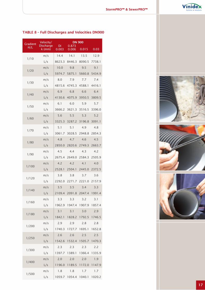
Choice of roughness Coefficients
tables 4 to 8 give the velocities and flow rates for StormPRO™ and SewerPRO™ pipes flowing full for k =0.003, 0.006, 0.015 and 0.03mm. AS 2200 – Design charts for water supply and sewerage – recommends values in the range 0.003 to 0.015mm for clean, concentrically jointed thermoplastics pipes and AS 3500.3 – National plumbing and drainage, Part 3 Stormwater drainage – specifies 0.015mm for design of plastics stormwater pipe drains for normal conditions.
However, it is important to note that factors such as slime growth and accumulation of debris can affect the selection of roughness coefficient in some circumstances. In addition, local utilities may have preferred values for design of their systems. For flow under alternative conditions contact Vinidex or use the Vinidex Fluff program.
For partial flow, consult Figure C for adjustment factors.
FiGure C – proportional Depth, velocity and Discharge for partially Full pipes
DEPTH TODIAMETER
RATIOdD
1.0
0.9
0.8
0.7
0.6
0.5
0.4
0.3
0.2
0.1
DISCHARGE
0.0 0.1 0.2 0.3 0.4 0.5 0.6 0.7 0.8 0.9 1.0 1.31.21.1
VELOCITY
HYDRAULIC RATIOS V PART AND Q PARTV FULL Q FULL
n VARIABLE WITH DEPTH
n CONSTANT

stormprO™ & sewerprO™
13
tABle 4 – Full Discharges and velocities Dn150 – Dn225
Gradient H/L
Velocity/ Discharge
k (mm)
Dn 150 Dn 225Di
0.0030.148 0.006
Di 0.003
0.226 0.0060.015 0.03 0.015 0.03
1/10m/s 4.8 4.7 4.6 4.4 6.2 6.2 5.9 5.7
L/s 82.2 81.0 78.4 75.3 250.7 246.9 238.3 228.6
1/20m/s 3.3 3.2 3.2 3.0 4.3 4.2 4.1 4.0
L/s 56.4 55.8 54.3 52.5 172.4 170.4 165.5 159.6
1/30m/s 2.6 2.6 2.5 2.5 3.5 3.4 3.3 3.2
L/s 45.2 44.8 43.7 42.4 138.4 137.0 133.5 129.2
1/40m/s 2.2 2.2 2.2 2.1 3.0 2.9 2.9 2.8
L/s 38.6 38.3 37.5 36.4 118.4 117.3 114.6 111.1
1/50m/s 2.0 2.0 1.9 1.9 2.6 2.6 2.5 2.5
L/s 34.2 33.9 33.2 32.4 104.8 104.0 101.7 98.8
1/60m/s 1.8 1.8 1.8 1.7 2.4 2.3 2.3 2.2
L/s 30.9 30.7 30.1 29.4 94.9 94.2 92.3 89.7
1/70m/s 1.7 1.6 1.6 1.6 2.2 2.2 2.1 2.1
L/s 28.4 28.2 27.7 27.0 87.2 86.6 84.9 82.7
1/80m/s 1.5 1.5 1.5 1.5 2.0 2.0 2.0 1.9
L/s 26.4 26.2 25.8 25.2 81.1 80.5 79.1 77.1
1/90m/s 1.4 1.4 1.4 1.4 1.9 1.9 1.8 1.8
L/s 24.7 24.6 24.2 23.6 76.0 75.5 74.2 72.4
1/100m/s 1.4 1.3 1.3 1.3 1.8 1.8 1.7 1.7
L/s 23.3 23.2 22.8 22.3 71.8 71.3 70.1 68.4
1/120m/s 1.2 1.2 1.2 1.2 1.6 1.6 1.6 1.5
L/s 21.1 21.0 20.7 20.3 64.9 64.6 63.5 62.1
1/140m/s 1.1 1.1 1.1 1.1 1.5 1.5 1.5 1.4
L/s 19.4 19.3 19.0 18.6 59.7 59.3 58.5 57.2
1/160m/s 1.0 1.0 1.0 1.0 1.4 1.4 1.4 1.3
L/s 18.0 17.9 17.7 17.3 55.5 55.2 54.4 53.3
1/180m/s 1.0 1.0 1.0 0.9 1.3 1.3 1.3 1.2
L/s 16.9 16.8 16.6 16.3 52.0 51.7 51.0 50.0
1/200m/s 0.9 0.9 0.9 0.9 1.2 1.2 1.2 1.2
L/s 15.9 15.8 15.6 15.4 49.1 48.8 48.2 47.3
1/250m/s 0.8 0.8 0.8 0.8 1.1 1.1 1.1 1.0
L/s 14.0 14.0 13.8 13.6 43.4 43.2 42.7 41.9
1/300m/s 0.7 0.7 0.7 0.7 1.0 1.0 1.0 0.9
L/s 12.7 12.6 12.5 12.3 39.2 39.1 38.6 38.0
1/400m/s 0.6 0.6 0.6 0.6 0.8 0.8 0.8 0.8
L/s 10.8 10.8 10.7 10.5 33.5 33.3 33.0 32.5
1/500m/s 0.6 0.6 0.5 0.5 0.7 0.7 0.7 0.7
L/s 9.5 9.5 9.4 9.3 29.6 29.5 29.2 28.8

stormprO™ & sewerprO™
14
Gradient H/L
Velocity/ Discharge
k (mm)
Dn 300 Dn 375Di
0.0030.3
0.006Di
0.0030.374 0.0060.015 0.03 0.015 0.03
1/10m/s 7.5 7.3 7.1 6.8 8.6 8.4 8.1 7.8
L/s 527.7 519.1 500.1 479.4 940.8 924.8 889.8 852.4
1/20m/s 5.1 5.1 4.9 4.7 5.9 5.8 5.6 5.4
L/s 363.6 359.0 348.0 335.2 649.0 640.3 619.9 596.7
1/30m/s 4.1 4.1 4.0 3.8 4.7 4.7 4.6 4.4
L/s 292.1 288.9 281.1 271.6 521.8 515.7 501.1 483.8
1/40m/s 3.5 3.5 3.4 3.3 4.1 4.0 3.9 3.8
L/s 250.0 247.5 241.4 233.8 446.8 442.1 430.6 416.6
1/50m/s 3.1 3.1 3.0 2.9 3.6 3.6 3.5 3.4
L/s 221.5 219.5 214.4 208.0 396.0 392.2 382.7 370.8
1/60m/s 2.8 2.8 2.8 2.7 3.3 3.2 3.2 3.1
L/s 200.6 198.9 194.6 189.0 358.8 355.6 347.4 337.1
1/70m/s 2.6 2.6 2.5 2.5 3.0 3.0 2.9 2.8
L/s 184.5 183.0 179.2 174.3 330.0 327.2 320.1 311.0
1/80m/s 2.4 2.4 2.4 2.3 2.8 2.8 2.7 2.6
L/s 171.5 170.2 166.9 162.5 307.0 304.5 298.1 289.9
1/90m/s 2.3 2.3 2.2 2.2 2.6 2.6 2.5 2.5
L/s 160.9 159.7 156.7 152.7 287.9 285.7 280.0 272.5
1/100m/s 2.1 2.1 2.1 2.0 2.5 2.5 2.4 2.3
L/s 151.9 150.8 148.1 144.4 271.9 269.9 264.7 257.8
1/120m/s 1.9 1.9 1.9 1.9 2.2 2.2 2.2 2.1
L/s 137.5 136.6 134.3 131.1 246.2 244.6 240.1 234.2
1/140m/s 1.8 1.8 1.7 1.7 2.1 2.0 2.0 2.0
L/s 126.4 125.6 123.6 120.8 226.4 225.0 221.1 215.9
1/160m/s 1.7 1.7 1.6 1.6 1.9 1.9 1.9 1.8
L/s 117.5 116.8 115.0 112.5 210.5 209.2 205.8 201.1
1/180m/s 1.6 1.6 1.5 1.5 1.8 1.8 1.8 1.7
L/s 110.2 109.6 107.9 105.7 197.4 196.3 193.2 189.0
1/200m/s 1.5 1.5 1.4 1.4 1.7 1.7 1.7 1.6
L/s 104.0 103.4 102.0 99.9 186.4 185.3 182.5 178.7
1/250m/s 1.3 1.3 1.3 1.3 1.5 1.5 1.5 1.4
L/s 92.0 91.6 90.4 88.7 165.0 164.1 161.9 158.7
1/300m/s 1.2 1.2 1.2 1.1 1.4 1.4 1.3 1.3
L/s 83.2 82.9 81.9 80.4 149.3 148.6 146.7 143.9
1/400m/s 1.0 1.0 1.0 1.0 1.2 1.2 1.1 1.1
L/s 71.1 70.8 70.0 68.9 127.5 127.0 125.5 123.4
1/500m/s 0.9 0.9 0.9 0.9 1.0 1.0 1.0 1.0
L/s 62.8 62.6 62.0 61.1 112.8 112.4 111.2 109.5
tABle 5 – Full Discharges and velocities Dn300 – Dn375

stormprO™ & sewerprO™
15
tABle 6 – Full Discharges and velocities Dn450 – Dn525
Gradient H/L
Velocity/ Discharge
k (mm)
Dn 450 Dn 525Di
0.0030.448 0.006
Di 0.003
0.523 0.0060.015 0.03 0.015 0.03
1/10m/s 9.6 9.4 9.0 8.7 10.5 10.3 9.9 9.5
L/s 1509.7 1482.8 1425.3 1364.8 2263.4 2221.7 2133.7 2042.5
1/20m/s 6.6 6.5 6.3 6.1 7.3 7.2 6.9 6.7
L/s 1042.4 1027.7 994.0 956.2 1564.2 1541.1 1489.3 1431.9
1/30m/s 5.3 5.3 5.1 4.9 5.9 5.8 5.6 5.4
L/s 838.6 828.3 804.0 775.6 1258.8 1242.7 1205.2 1162.0
1/40m/s 4.6 4.5 4.4 4.2 5.0 5.0 4.8 4.7
L/s 718.3 710.4 691.2 668.2 1078.6 1066.2 1036.5 1001.4
1/50m/s 4.0 4.0 3.9 3.8 4.5 4.4 4.3 4.2
L/s 636.8 630.4 614.5 595.0 956.6 946.4 921.7 891.9
1/60m/s 3.7 3.6 3.5 3.4 4.0 4.0 3.9 3.8
L/s 577.1 571.7 558.0 541.1 867.1 858.5 837.3 811.3
1/70m/s 3.4 3.3 3.3 3.2 3.7 3.7 3.6 3.5
L/s 531.0 526.2 514.3 499.2 797.9 790.4 771.8 748.7
1/80m/s 3.1 3.1 3.0 3.0 3.5 3.4 3.3 3.3
L/s 494.0 489.8 479.1 465.5 742.4 735.8 719.2 698.3
1/90m/s 2.9 2.9 2.9 2.8 3.2 3.2 3.1 3.1
L/s 463.4 459.7 450.1 437.7 696.6 690.7 675.7 656.6
1/100m/s 2.8 2.8 2.7 2.6 3.1 3.0 3.0 2.9
L/s 437.7 434.3 425.5 414.1 658.0 652.6 638.9 621.4
1/120m/s 2.5 2.5 2.4 2.4 2.8 2.8 2.7 2.6
L/s 396.5 393.6 386.1 376.3 596.1 591.6 579.9 564.8
1/140m/s 2.3 2.3 2.3 2.2 2.6 2.5 2.5 2.4
L/s 364.6 362.1 355.6 347.0 548.3 544.4 534.2 520.8
1/160m/s 2.2 2.1 2.1 2.1 2.4 2.4 2.3 2.3
L/s 339.1 336.9 331.1 323.3 510.0 506.6 497.5 485.5
1/180m/s 2.0 2.0 2.0 1.9 2.2 2.2 2.2 2.1
L/s 318.0 316.1 310.9 303.8 478.4 475.3 467.2 456.3
1/200m/s 1.9 1.9 1.9 1.8 2.1 2.1 2.1 2.0
L/s 300.3 298.5 293.8 287.3 451.8 449.0 441.6 431.6
1/250m/s 1.7 1.7 1.7 1.6 1.9 1.9 1.8 1.8
L/s 265.9 264.5 260.6 255.3 400.1 397.9 391.8 383.5
1/300m/s 1.5 1.5 1.5 1.5 1.7 1.7 1.7 1.6
L/s 240.7 239.5 236.3 231.7 362.3 360.4 355.3 348.2
1/400m/s 1.3 1.3 1.3 1.3 1.4 1.4 1.4 1.4
L/s 205.7 204.8 202.3 198.7 309.7 308.3 304.3 298.8
1/500m/s 1.2 1.2 1.1 1.1 1.3 1.3 1.3 1.2
L/s 182.0 181.3 179.3 176.3 274.2 273.0 269.8 265.2

stormprO™ & sewerprO™
16
tABle 7 – Full Discharges and velocities Dn600 – Dn750
Gradient H/L
Velocity/ Discharge
k (mm)
Dn 600 Dn 750Di
0.0030.596 0.006
Di 0.003
0.731 0.0060.015 0.03 0.015 0.03
1/10m/s 11.4 11.2 10.7 10.3 12.9 12.7 12.2 11.6
L/s 3184.8 3124.5 2998.6 2869.6 5427.6 5320.2 5100.5 4879.5
1/20m/s 7.9 7.8 7.5 7.2 9.0 8.8 8.5 8.2
L/s 2202.4 2168.9 2094.3 2012.8 3757.2 3697.2 3565.8 3425.1
1/30m/s 6.4 6.3 6.1 5.9 7.2 7.1 6.9 6.6
L/s 1773.2 1749.7 1695.5 1634.0 3026.8 2984.5 2888.6 2781.9
1/40m/s 5.4 5.4 5.2 5.0 6.2 6.1 5.9 5.7
L/s 1519.7 1501.6 1458.6 1408.5 2595.3 2562.5 2486.2 2399.0
1/50m/s 4.8 4.8 4.7 4.5 5.5 5.4 5.3 5.1
L/s 1348.1 1333.2 1297.5 1254.9 2302.9 2276.0 2212.4 2138.0
1/60m/s 4.4 4.3 4.2 4.1 5.0 4.9 4.8 4.6
L/s 1222.1 1209.6 1178.8 1141.6 2088.3 2065.5 2010.7 1945.6
1/70m/s 4.0 4.0 3.9 3.8 4.6 4.5 4.4 4.3
L/s 1124.8 1113.8 1086.9 1053.7 1922.3 1902.5 1854.3 1796.2
1/80m/s 3.8 3.7 3.6 3.5 4.3 4.2 4.1 4.0
L/s 1046.6 1037.0 1012.9 982.9 1789.2 1771.6 1728.5 1676.0
1/90m/s 3.5 3.5 3.4 3.3 4.0 4.0 3.9 3.8
L/s 982.2 973.5 951.7 924.4 1679.3 1663.5 1624.5 1576.4
1/100m/s 3.3 3.3 3.2 3.1 3.8 3.7 3.7 3.6
L/s 927.9 920.0 900.1 874.9 1586.6 1572.4 1536.7 1492.3
1/120m/s 3.0 3.0 2.9 2.9 3.4 3.4 3.3 3.2
L/s 840.8 834.2 817.2 795.3 1438.1 1426.1 1395.6 1357.0
1/140m/s 2.8 2.8 2.7 2.6 3.2 3.1 3.1 3.0
L/s 773.5 767.8 752.9 733.6 1323.3 1312.9 1286.2 1252.0
1/160m/s 2.6 2.6 2.5 2.5 2.9 2.9 2.9 2.8
L/s 719.5 714.5 701.3 683.9 1231.2 1222.0 1198.3 1167.5
1/180m/s 2.4 2.4 2.4 2.3 2.8 2.7 2.7 2.6
L/s 675.0 670.5 658.6 642.8 1155.3 1147.0 1125.6 1097.6
1/200m/s 2.3 2.3 2.2 2.2 2.6 2.6 2.5 2.5
L/s 637.5 633.4 622.6 608.1 1091.3 1083.8 1064.3 1038.5
1/250m/s 2.0 2.0 2.0 1.9 2.3 2.3 2.3 2.2
L/s 564.8 561.5 552.6 540.6 967.1 961.0 945.0 923.5
1/300m/s 1.8 1.8 1.8 1.8 2.1 2.1 2.0 2.0
L/s 511.5 508.7 501.2 490.8 876.0 870.9 857.4 838.9
1/400m/s 1.6 1.6 1.5 1.5 1.8 1.8 1.8 1.7
L/s 437.3 435.2 429.5 421.3 749.4 745.5 735.0 720.5
1/500m/s 1.4 1.4 1.4 1.3 1.6 1.6 1.6 1.5
L/s 387.2 385.5 380.8 374.1 663.7 660.6 652.1 640.1
stormprO™ & sewerprO™
17
Gradient H/L
Velocity/ Discharge
k (mm)
Dn 900Di
0.0030.873 0.006 0.015 0.03
1/10m/s 14.4 14.1 13.5 12.9
L/s 8623.3 8446.3 8090.5 7738.1
1/20m/s 10.0 9.8 9.5 9.1
L/s 5974.7 5875.1 5660.8 5434.9
1/30m/s 8.0 7.9 7.7 7.4
L/s 4815.6 4745.3 4588.1 4416.1
1/40m/s 6.9 6.8 6.6 6.4
L/s 4130.6 4075.9 3950.5 3809.5
1/50m/s 6.1 6.0 5.9 5.7
L/s 3666.2 3621.3 3516.5 3396.0
1/60m/s 5.6 5.5 5.3 5.2
L/s 3325.3 3287.2 3196.8 3091.1
1/70m/s 5.1 5.1 4.9 4.8
L/s 3061.7 3028.5 2948.8 2854.3
1/80m/s 4.8 4.7 4.6 4.5
L/s 2850.0 2820.6 2749.3 2663.7
1/90m/s 4.5 4.4 4.3 4.2
L/s 2675.4 2649.0 2584.3 2505.9
1/100m/s 4.2 4.2 4.1 4.0
L/s 2528.1 2504.1 2445.0 2372.5
1/120m/s 3.8 3.8 3.7 3.6
L/s 2292.0 2271.7 2221.0 2157.9
1/140m/s 3.5 3.5 3.4 3.3
L/s 2109.4 2091.8 2047.4 1991.4
1/160m/s 3.3 3.3 3.2 3.1
L/s 1962.9 1947.4 1907.9 1857.4
1/180m/s 3.1 3.1 3.0 2.9
L/s 1842.1 1828.2 1792.5 1746.5
1/200m/s 2.9 2.9 2.8 2.8
L/s 1740.3 1727.7 1695.1 1652.8
1/250m/s 2.6 2.6 2.5 2.5
L/s 1542.6 1532.4 1505.7 1470.3
1/300m/s 2.3 2.3 2.3 2.2
L/s 1397.7 1389.1 1366.4 1335.9
1/400m/s 2.0 2.0 2.0 1.9
L/s 1196.0 1189.5 1172.0 1147.9
1/500m/s 1.8 1.8 1.7 1.7
L/s 1059.7 1054.4 1040.1 1020.2
tABle 8 – Full Discharges and velocities Dn900

stormprO™ & sewerprO™
18
DesiGn
structural Design
Under general gravity drainage and sewer pipe laying conditions, detailed calculations predicting pipe performance are not necessary. Following an extensive study of installed pipe performance, the European Plastic Pipe and Fitting Association (TEPPFA) concluded that final deflection of pipes was controlled by the settlement of the soil after installation. Where installation was controlled, or self-compacting granular material were used, pipe deflections were consistently low regardless of installation depth and traffic or other loads.
Where StormPRO™ and SewerPRO™ pipes are to be installed in normal conditions at depths up to 6m such that the depth to diameter ratio is at least 2, design calculations
are not required. Simply following the recommended installation procedures will ensure that deflections are controlled. This is particularly true for installations under roadways, where the level of compaction required to prevent subsidence of the pavement also provides a highly supportive structural environment for the pipe.
For unusual conditions, or depths greater than 6 metres, design calculations may be performed in accordance with AS/NZS 2566.1. The structural design aspects of buried flexible pipes to be considered are vertical deflection, ring bending strain and buckling.
The following typical values may be used in pipe design:
property symbol value
Short Term Stiffness – StormPRO™ SDI 8000 N/m
Short Term Stiffness – SewerPRO™ SDI 10000 N/m
Allowable long term deflection 7.5%
Allowable long term ring bending strain 4%
Long Term Stiffness – StormPRO™ SDL2 2500 N/m/m
Long Term Stiffness – SewerPRO™ SDL2 3000 N/m/m

stormprO™ & sewerprO™
19
instAllAtiOn
General
The following section provides general guidance for the installation of Vinidex StormPRO™ and SewerPRO™ pipes. For more detailed information refer to AS/NZS 2566.2 – Buried flexible pipelines: Part 2, Installation.
Handling and storage
Being manufactured from tough polyprop-ylene, StormPRO™ and SewerPRO™ pipes are robust and are suitable for use in all site conditions. The pipes are relatively light weight and can generally be manhandled. However, care should be taken when pipes are loaded, unloaded, stacked or distributed on sites.
When pipes are lifted mechanically, web or rope slings should be used. Pipes should not be allowed to overhang by more than 1 metre. Transport should not have sharp projections which could cause damage to pipes. Pipes should not be dragged along the ground as this can damage the pipe, causing difficulty with jointing and testing.
StormPRO™ and SewerPRO™ pipes should be stacked on flat firm ground, which has been cleared of debris. Pipes should be laid flat on transverse bearers at least 75mm wide at maximum 1.5m centres.
Pipe sockets should be supported so that the ends are free from loading, with sockets in each layer opposite to the previous layer. Different sizes are best stacked separately. If this is not practical, then stack with the largest pipes at the base. Framed crates must be stored timber on timber and may go up three crates but should not exceed 3m in height. If pipes are to be nested for long periods, stacks should not exceed 2m in height.
Rubber rings should be stored away from direct sunlight or weathering. Rubber rings should never be placed on the ends of pipes which are being stored.
tABle 9 – standard pack sizes of stormprO™ and sewerprO™ pipe
Dn number of pipes per Crate
150 30
225 12
300 6
375 6
450 4
525 6
600 3
750 2
900 2

stormprO™ & sewerprO™
20
instAllAtiOn
trench preparation
The trench should not be excavated too far in advance of pipe laying and should be back filled as soon as possible. The trench width should be as narrow as is practicable, but wide enough to allow compaction of the embedment material on either side of the pipe.
The trench should be excavated deep enough to allow for the specified grade, the required depth of embedment material below the bottom of the pipe, and the minimum cover, H. General trench terminology is given in Figure D, and typical minimum covers are given in table 10.
FiGure D: General trench Cross section
tABle 10 – minimum Cover Over pipe
loading Condition minimum Cover H (m)
Not subject to vehicular loading 0.30
Land zoned for agricultural use 0.60
Subject to vehicular loading:
(a) no carriageway(b) sealed carriageways(c) unsealed carriageways
0.450.600.75
Pipelines in embankments or subject to construction equipment loads
0.75
TRENCH FILL
EMBEDMENTMATERIAL
FOUNDATION
TRENCH WALL
FINISHEDSURFACE

stormprO™ & sewerprO™
21
instAllAtiOn
Jointing
The StormPRO™ and SewerPRO™ joint utilises a push-fit compression ring retained between the last two corrugations on the spigot. The joint is formed by a sliding assembly action between the spigot and a lubricated socket. The joint is simple, precise and reliable. The rings do not roll and cannot be displaced.
1. Clean pipe spigots & sockets
All dust, dirt and grit which could prevent an effective seal must be removed from pipe ends and sockets.
2. position sealing rings
The correct position for the sealing ring is between the first and second corrugations from the pipe spigot end. Ensure the sealing ring is correctly sealed and not twisted. The ring will be under slight tension, thus ensuring good underside contact. The ring can be removed for cleaning and securely re-seated.
3. Apply lubricant
Vinidex lubricant should be applied generously to the whole of the inside area of the socket. Make sure the lubricated socket does not become contaminated with dirt.
4. make Joint
Offer up pipe to socket, align pipe and push home to the witness mark. A small depression in the trench bedding immediately underneath the socket will keep the socket clear of material during jointing. Alignment is important to facilitate jointing. Improper alignment will make it difficult to joint.
A good method is to lift the spigot end of the pipe by passing a rope underneath. This makes it easier to align spigot into socket. The pipe may be subsequently deflected to line and gradient. Any such subsequent deflection should be limited to 3̊ . The force required to push the pipe home will vary according to pipe size and ambient temperature.
Whatever method is used to apply the necessary force, care must be taken to ensure that there is no risk of damaging the pipe. The most convenient method is to use a lever ensuring the pipe end is protected.
A common technique is the use of a bar and block to apply the jointing force. Mechanically pulling or pushing methods are unnecessary and may introduce undue force. If circumstances dictate that such methods have to be used, over-insertion should be avoided. Pulling must be with fabric straps and not chains around the pipe.
Cutting of pipes
StormPRO™ and SewerPRO™ pipes may be cut anywhere along their length as required. The cut should be made in the valley between the corrugations at right angles to the axis of the pipe using a suitable saw. A chamfer is not required.

stormprO™ & sewerprO™
22
instAllAtiOn
selection of embedment material
Embedment material for StormPRO™ and SewerPRO™ pipes should preferably be granular, free-flowing material with a maximum particle size of 14mm for DN150 pipe and 20mm for larger pipes.
This type of embedment material requires less compactive effort to provide support for the pipe and minimise soil settlement. Consult AS/NZS 2566.2 for more information.
pipe laying
The bedding material should be placed and graded to invert level, and compacted as required. In conditions where the trench bottom is wet, soft or irregular, it may be necessary to first stabilise, fill and level, and compact the base. In order to ensure uniform support along the pipe barrel, a small indentation should be excavated in the pipe bedding zone to accommodate the pipe sockets.
The pipe side support material should be placed evenly on both sides of the pipeline and compacted such that relative compaction
is consistent with design. Side support material should be worked under the sides of the pipe to minimise voids and provide maximum pipe haunching, taking care to minimise distortion of the pipe and maintain alignment and grade. The pipe overlay material should be levelled and compacted in layers, to a minimum height of l00mm above the crown of the pipe, or as specified.
Backfill should be placed on the pipe overlay and compacted as specified but generally not in layers in excess of 300mm. Complete the backfilling operation to finished surface levels.
Connection to structures
StormPRO™ and SewerPRO™ pipes may be connected to rigid structures without the use of short rocker pipes. StormPRO™ and SewerPRO™ pipes have sufficient flexi-bility and strain tolerance to accommodate differential settlement at the interface. Figure e shows a typical entry or exit to a concrete structure.
FiGure e – typical entry or exit to a Concrete structure
150 TYP
HYDROPHILIC SEAL
SEWERPRO
UNDISTURBED NATIVE SOIL
APPROVED BEDDING MATERIAL
75 TYP
BENCHING
CONCRETE ACCESS CHAMBER

stormprO™ & sewerprO™
23
instAllAtiOn
leakage testing
Leakage testing is carried out to identify installation faults and sources of infiltration and exfiltration in pipelines which are required to be water tight such as sewerage systems. Leakage testing is generally not required for stormwater drains.
AS/NZS 2566.2 specifies detailed procedures for leakage testing using hydrostatic testing, air or vacuum testing or infiltration testing of non pressure pipelines. These methods are summarised as below. Notwithstanding this, leakage testing should be carried out in accordance with local authority requirements.
method 1: Hydrostatic test
Fill the pipeline with water and pressurise to not less than 20kPa at the highest point of the section being tested, but not greater than 60kPa at the lowest point of the test section. Maintain the test pressure for at least two hours by adding measured volumes of water if required. Each joint should be carefully examined visually for leaks, and any defects should be repaired. The pipeline section is deemed satisfactory if the make-up volume is less that 0.5L per hour per metre length per metre diameter. After any repairs, the pipeline should be re-tested.
method 2: Air test
Introduce air slowly by suitable means
until a pressure of 25kPa is obtained. Maintain for a period of at least 3 minutes. If no leaks are observed after 3 minutes, shut off the air supply. If the pressure of air contained in the pipes under test does not fall below 18kPa within the time period specified in Table 11 below, the pipeline shall be considered satisfactory.
If, however, the pressure is not maintained within the specified limits, reintroduce the air and examine the pipeline for leaks by pouring a concentrated solution of soft soap and water over the joints and fittings. Identify and repair any leaks. After any repairs, the pipeline should be re-tested.
method 3: vacuum test
Apply a vacuum until a negative pressure of 25 kPa is obtained. Maintain for a period of at least 3 minutes. If no leaks are observed after 3 minutes, isolate the test section from the vacuum pump. Monitor the pressure for the time specified in table 11. If the vacuum does not drop below 18 kPa within the specified time period, the pipeline shall be considered satisfactory. Where the pipeline section fails the test, re-apply the vacuum and examine the pipeline for leaks. Identify and repair any leaks. After any repairs, the pipeline should be re-tested.
tABle 11 – minimum time intervals for 7kpa pressure Change in Air and vacuum test
test length (metres)Dn 50 100 150 200 250
minimum test Duration (minutes)
150 3 3 3 5 6
225 4 5 8 10 13
300 6 9 14 18 23
375 7 14 22 29 36
450 10 21 31 41 52
525 14 28 42 56 70
600 18 37 55 73 92
750 29 57 86 115 143
900 41 83 124 165 207
method 4: infiltration test
Where there is a free standing water table at a height of at least 1.5m above the test section, an infiltration test can be carried
out. Observe the pipe for 24 hours. Where infiltration is detected, the leak should be identified and repaired.

stormprO™ & sewerprO™
24
Cut-ins AnD repAirs
Cut-ins
To cut into an existing buried StormPRO™ or SewerPRO™ pipeline and install a socketed junction or other socketed fitting, the following procedure should be adopted:
step 1
Expose the existing pipe and cut out a length equal to the effective length of the fitting, plus approximately 600mm.
step 2
Connect 300mm long short pipes to the junction sockets and fit rubber rings to the spigot ends of the short pipes.
step 3
Fit slip couplings to the cut ends of the existing pipe and install junction.
repairs
When selecting the required repair method, it is necessary to differentiate between minor and more extensive damage.
Minor or localised damage should be limited to small holes in the pipe. In these situations, bolt tensioned wrap-around stainless steel repair fittings can be used. It is important to note that this type of fitting has no positive stop and must only be tightened in accordance with the manufacturers’ torque settings.
Damage caused by excavation or other machinery will inevitably affect the structural integrity of the pipe and should be cut out and replaced using slip couplings.


AustrAliAn OperAtiOns
new south Wales
254 Woodpark Rd Smithfield NSW 2164
Tel: (02) 9604 2422 Fax: (02) 9604 1078
101 Byrnes Rd Nth Wagga Wagga NSW 2164
Tel: (02) 9671 9312 Fax: (02) 971 9286
CustOmer serviCe
sales Hotline: 13 11 69 sales Fax: 13 24 43
email: [email protected] Web: www.vinidex.com.au
victoria
Unit 1, 10 Duerdin St Notting Hill VIC 3168
Tel: (03) 9543 2311 Fax: (03) 9543 7420
231-245 St. Albans Rd Sunshine VIC 3020
Tel: (03) 9364 8187 Fax: (03) 9311 6230
south Australia
9–11 Kaurna Ave Edinburgh SA 5111
Tel: (08) 8250 8940 Fax: (08) 8250 1625
tasmania
15 Thistle St Sth Launceston TAS 7249
Tel: (03) 6344 2521 Fax: (03) 6343 1100
Queensland
224 Musgrave Rd Coopers Plains QLD 4108
Tel: (07) 3277 2822 Fax: (07) 3277 9500
49 Enterprise Ave Bohle QLD 4816
Tel: (07) 4759 0999 Fax: (07) 4774 5728
northern territory
3846 Marjorie St Pinelands NT 0829
Tel: (08) 8932 8200 Fax: (08) 8932 8211
Western Australia
Sainsbury Rd O’Connor WA 6163
Tel: (08) 9337 4344 Fax: (08) 9331 3383
COrpOrAte HeAD OFFiCe
vinidex pty limited ABN 42 000 664 942
19–21 Loyalty Road PO Box 4990 North Rocks NSW 2151
Tel: +61 2 8839 9006 Fax: +61 2 8839 9152
vin 264