Embed Size (px)
Citation preview

StormPRO® & SewerPRO®
Twin-Walled Corrugated Polypropylene Pipe and Fittings System for Non-Pressure Applications
LIGHT WEIGHT
EASY TO HANDLE - COST EFFECTIVE TO INSTALL
SIMPLE & EFFECTIVE JOINTS
ADAPTS TO SOIL MOVEMENT
DOMESTIC OR INDUSTRIAL APPLICATIONS
USED IN AGGRESSIVE OR SALINE SOILSQuality ISO 9001Lic 570

StormPRO® & SewerPRO®
1
2
STORMPRO® AND SEWERPRO®
INTRODUCTION 3
PRODUCT RANGE 5
Pipe 5
Fittings 6
PRODUCT DATA 12
Pipe Dimensions 12
Dimensions & Effective Lengths 12
Joint Details 13
Chemical Resistance 14
Temperature 14
Weathering Resistance 14
Manufacture 14
Standards 14
Material Properties 15
DESIGN 16
Structural Design 16
Hydraulic Design 18
Choice of Roughness Coefficients 19
INSTALLATION 25
Flexible Pipes 25
Handling & Storage 26
Trench Excavation 26
Minimum Trench Width 26
Pipes in Parallel 27
Selection of Embedment Material 28
Placing and Compacting Embedment Material 29
Cutting of Pipes 29
Jointing Instructions 30
Angular Deflection 31
Witness Mark 31
Internal Lining 31
Backfilling 31
Allowable Cover 31
Construction Loads 32
Flotation 32
Concrete Encasement 33
Connection to Structures 34
Above-Ground Installation 34
Stormwater Connections 35
Field Testing 37
Water Jet Cleaning 38
Cut-Ins & Repairs 39

3
StormPRO® & SewerPRO®
INTRODUCTION
Vinidex StormPRO® and SewerPRO®
provide the sewer and stormwater markets with a modern pipe and fittings system for non-pressure applications.
StormPRO® and SewerPRO® pipes are twin-wall, corrugated polypropylene pipes for non-pressure applications, manufacturedin accordance with AS/NZS 5065.
Utilising modern co-extrusion techniques, StormPRO® and SewerPRO® are manufacturedwith a smooth bore for optimum hydraulic performance and a corrugated outside wall for high stiffness to weight ratio.
SewerPRO® and StormPRO® pipes combine the strength and toughness of advanced polypropylene materials with a structured wall design.
SewerPRO® provides a cost effective pipe for sewer applications with a full range of fittings to suit different designs and installations. SewerPRO® pipe is a comprehensive solution for sewer needs.
StormPRO® has its own fittings specially designed for stormwater needs, providing a cost-effective system for drainage applications.
Vinidex StormPRO® and SewerPRO® can be installed in trafficable areas including under road pavements and non-trafficable areas. SewerPRO® and StormPRO® are sensitive to the environment, with their material efficient design reducing raw material usage, long life and recyclability at the end of life contributing to reduced environmental needs.
SewerPRO® and StormPRO® are less likely to crack than rigid pipe, resulting in less leakage and consequential environmental issues.

StormPRO® & SewerPRO®
1
4
WHY CHOOSE VINIDEX STORMPRO®
& SEWERPRO® CORRUGATED POLYPROPYLENE PIPE SYSTEM?A full system solution in sizes fromDN150 to DN900.
3 Lower total installed cost• Light weight product, easy to
handle• Less heavy lifting equipment
required• Pipes easy to cut• Ease of jointing
3 Introducing the improved PRO2® joint• Reduced jointing forces• Enhanced joint performance
under adverse soil movement and deflection conditions
• New rubber ring design• The new PRO2 joint is not
compatible with the old joint or rubber rings. Make sure you only use Vinidex fittings labelled PRO2 with Vinidex PRO2 pipes to ensure dimensional compatibility and system performance. Note that systems may not be leak-tight if PRO2 fittings are not used.
• PRO2 sockets should only be joined using PRO2 rubber rings
3 Optimum hydraulic performance• Smooth inner skin for hydraulic
flow• Surface is resistant to build up• Pipes easy to cut• Ease of jointing
3 Can be used in aggressive or saline soils, sensitive to the environment
3 Light internal colour to facilitate video inspection
3 Optimum hydraulic performance• Polypropylene (PP), Polyethylene
(PE) and Polyvinyl Chloride (PVC) materials are used in PRO fittings
• All fittings are SN8 minimum• Vinidex offers a range of
adaptors to connect to non PRO systems
• Special fittings can also be provided, contact Vinidex for more information
Note: Fittings DN450 and larger are generally not stocked. Contact Vinidex for price and availability.
STORMPRO® FITTINGS, ACCESSORIES & TOOLS
Vinidex also offers fittings, accessories and tools specifically designed for StormPRO applications.
The PROgrommet is a quick and easy system to install 100m and 150mm connections to StormPRO pipe.
The PROsaw has been specifically designed to accommodate the PRO rib height and for simple installation of the PROgrommet.

5
StormPRO® & SewerPRO®
PRODUCT RANGE
PipeVinidex SewerPRO® pipes are designed for sewerage applications and StormPRO® used for stormwater applications. SewerPRO® has a dark grey coloured corrugated outside surface and a smooth light grey interior. StormPRO® has a black coloured corrugated outside surface and a smooth light grey interior.
Each length of SewerPRO® and StormPRO® pipe is supplied with the rubber rings required for jointing. SewerPRO® and StormPRO® pipe is available in standard rubber ring jointed spigot/socket configuration (Sp/So). SewerPRO® comes in 3m nominal lengths and StormPRO® comes in 6m nominal lengths. Please see below tables for Product Data.
StormPRO® Polypropylene Pipe – Nominal 6m Length
VinidexCode
Nominal Diameter
(mm)Product Description Comments
29479 150 150 StormPRO2 SN8 PP 6.02m
29456 225 225 StormPRO2 SN8 PP 5.99m
29458 300 300 StormPRO2 SN8 PP 5.94m
29460 375 375 StormPRO2 SN8 PP 5.93m
29471 450 450 StormPRO2 SN8 PP 5.95m
29473 525 525 StormPRO2 SN8 PP 5.89m
29475 600 600 StormPRO2 SN8 PP 5.85m
29418 750 750 StormPRO2 SN8 PP 5.92m Reduced Spigot
29419 900 900 StormPRO2 SN8 PP 5.94m Reduced Spigot
Available in other lengths for projects. Sufficient Lubricant is supplied with pipe. Additional Lubricant may be ordered if required.
StormPRO® Polypropylene Pipe – Nominal 3m Length
VinidexCode
Nominal Diameter
(mm)Product Description Comments
29485 225 225 StormPRO2 SN8 PP 2.92m
29406 300 300 StormPRO2 SN8 PP 2.88m
29407 375 375 StormPRO2 SN8 PP 2.87m
29482 450 450 StormPRO2 SN8 PP 2.86m
29453 525 525 StormPRO2 SN8 PP 2.80m
29484 600 600 StormPRO2 SN8 PP 2.76m
29454 750 750 StormPRO2 SN8 PP 2.82m
29405 900 900 StormPRO2 SN8 PP 2.81m
Available in other lengths for projects. Sufficient Lubricant is supplied with pipe. Additional Lubricant may be ordered if required.
SewerPRO® Polypropylene Pipe – Nominal 3m Length
VinidexCode
Nominal Diameter
(mm)Product Description Comments
29480 150 150 SewerPRO2 SN10 PP 2.95m
29457 225 225 SewerPRO2 SN10 PP 2.92m
29459 300 300 SewerPRO2 SN10 PP 2.87m
29461 375 375 SewerPRO2 SN10 PP 2.86m
29472 450 450 SewerPRO2 SN10 PP 2.86m
29474 525 525 SewerPRO2 SN10 PP 2.80m
29476 600 600 SewerPRO2 SN10 PP 2.76m
29427 750 750 SewerPRO2 SN10 PP 2.82m Reduced Spigot
29428 900 900 SewerPRO2 SN10 PP 2.81m Reduced Spigot
Available in other lengths for projects.
Note: Rubber Rings are normally supplied with all pipes and fittings. Additional rubber rings may be ordered if required.

StormPRO® & SewerPRO®
1
6
Fittings
PRO Shorts
Vinidex Code
Size(mm) Product Description Availability
30344 150 150 PRO MHole SP SN10 600mm PP
30346 225 225 PRO MHole SP SN10 600mm PP
30563 300 300 PRO MHole SP SN10 600mm PP
30565 375 375 PRO MHole SP SN10 600mm PP
30348 450 450 PRO MHole SP SN10 600mm PP
30350 525 525 PRO MHole SP SN10 600mm PP
30352 600 600 PRO MHole SP SN10 600mm PP
30354 750 750 PRO MHole SP SN10 600mm PP
Rubber RingsRubber Rings are normally supplied with all pipes and fittings. Additional rubber rings may be ordered if required.
VinidexCode
Size DN(mm) Product Description Availability
83449 150 150 PRO2 PP Ring EPDM
83401 225 225 PRO2 PP Ring EPDM
83444 300 300 PRO2 PP Ring EPDM
83445 375 375 PRO2 PP Ring EPDM
83446 450 450 PRO2 PP Ring EPDM
83447 525 525 PRO2 PP Ring EPDM
83448 600 600 PRO2 PP Ring EPDM
83426 750 750 PRO2 PP Ring EPDM
83391 900 900 PRO2 PP Ring EPDM
Rubber Rings for use with Slip Couplings
VinidexCode
Size DN(mm) Product Description Availability
83416 750 750 PRO2 PP SlipCoup Ring EPDM
83417 900 900 PRO2 PP SlipCoup Ring EPDM
PRO Couplings
Vinidex Code
Size(mm) Product Description Availability
30568 150 150 PRO Coupling SN8 PVC
30320 225 225 PRO Coupling SN8 PVC
30321 300 300 PRO Coupling SN8 PVC
30322 375 375 PRO Coupling SN8 PVC
30323 450 450 PRO Coupling RMPE Contact Vinidex
30324 525 525 PRO Coupling RMPE Contact Vinidex
30325 600 600 PRO Coupling RMPE Contact Vinidex
PRO Slip Couplings
Vinidex Code
Size(mm) Product Description Availability
30450 150 150 PRO Slip Coupling SN8 PVC
30451 225 225 PRO Slip Coupling SN8 PVC
30452 300 300 PRO Slip Coupling SN8 PVC
30453 375 375 PRO Slip Coupling SN8 PVC
30454 450 450 PRO Slip Coupling RMPE Contact Vinidex
30455 525 525 PRO Slip Coupling RMPE Contact Vinidex
30456 600 600 PRO Slip Coupling RMPE Contact Vinidex
30457 750 750 PRO Slip Coupling PE Contact Vinidex
30458 900 900 PRO Slip Coupling PE Contact Vinidex
PVC and PE
PE
Note: Rubber Rings are normally supplied with all pipes and fittings. Additional rubber rings may be ordered if required.
PP

7
StormPRO® & SewerPRO®
15 Degree PRO Bends
VinidexCode
Size(mm) Product Description Comments
30245 150 150 PRO Bend 15D SN8 FF PVC Contact Vinidex
30238 225 225 PRO Bend 15D SN8 FF PVC Contact Vinidex
30247 300 300 PRO Bend 15D SN8 FF PVC Contact Vinidex
30248 375 375 PRO Bend 15D SN8 FF PVC Contact Vinidex
22.5 Degree PRO Bends
VinidexCode
Size(mm) Product Description Comments
30249 150 150 PRO Bend 22.5D SN8 FF PVC Contact Vinidex
30250 225 225 PRO Bend 22.5D SN8 FF PVC Contact Vinidex
30251 300 300 PRO Bend 22.5D SN8 FF PVC Contact Vinidex
30252 375 375 PRO Bend 22.5D SN8 FF PVC Contact Vinidex
30 Degree PRO Bends
Vinidex Code
Size(mm) Product Description Availability
30253 150 150 PRO Bend 30D SN8 FF PVC Contact Vinidex
30254 225 225 PRO Bend 30D SN8 FF PVC Contact Vinidex
30255 300 300 PRO Bend 30D SN8 FF PVC Contact Vinidex
30256 375 375 PRO Bend 30D SN8 FF PVC Contact Vinidex
30477 450 450 PRO Bend 30D SN10 MF PP Contact Vinidex
30319 600 600 PRO Bend 30D SN10 MF PP Contact Vinidex
45 Degree PRO Bends
Vinidex Code
Size(mm) Product Description Availability
30548 150 150 PRO Bend 45D SN10 FF PP
32571 225 225 PRO Bend 45D SN8 FF PVC
32580 300 300 PRO Bend 45D SN8 FF PVC
32592 375 375 PRO Bend 45D SN8 FF PVC
32416 450 450 PRO Bend 45D SN10 MF PP Contact Vinidex
32418 525 525 PRO Bend 45D SN10 MF PP Contact Vinidex
32420 600 600 PRO Bend 45D SN10 MF PP Contact Vinidex
30555 750 750 PRO Bend 45D SN10 MF PP Contact Vinidex
30556 900 900 PRO Bend 45D SN10 MF PP Contact Vinidex
88 Degree PRO Bends
Vinidex Code
Size(mm) Product Description Availability
30539 150 150 PRO Bend 88D SN10 FF PP
32572 225 225 PRO Bend 88D SN8 FF PVC
32581 300 300 PRO Bend 88D SN8 FF PVC
32593 375 375 PRO Bend 88D SN8 FF PVC
32417 450 450 PRO Bend 88D SN10 MF PP Contact Vinidex
32419 525 525 PRO Bend 88D SN10 MF PP Contact Vinidex
32421 600 600 PRO Bend 88D SN10 MF PP Contact Vinidex
30546 750 750 PRO Bend 88D SN10 MF PP Contact Vinidex
30547 900 900 PRO Bend 88D SN10 MF PP Contact Vinidex
Note: Rubber Rings are normally supplied with all pipes and fittings. Additional rubber rings may be ordered if required.
F&F PP
M&F PPPVC
PVC
PVC
PVC M&F PP
PVC
PP
M&F PP

StormPRO® & SewerPRO®
1
8Note: Rubber Rings are normally supplied with all pipes and fittings. Additional rubber rings may be ordered if required.
45 Degree PRO Junctions
VinidexCode
Size(mm) Product Description Availability
30490 150 150 PRO Jun 45D SN10 FF PP
32574 225 x 150 225x150 PRO Jun 45D SN8 FF PVC
32575 225 225 PRO Jun 45D SN8 FF PVC
32583 300 x 150 300x150 PRO Jun 45D SN8 FF PVC
32584 300 x 225 300x225 PRO Jun 45D SN8 FF PVC Contact Vinidex
32585 300 300 PRO Jun 45D SN8 FF PVC
32595 375 x 150 375x150 PRO Jun 45D SN8 FF PVC
32596 375 x 225 375x225 PRO Jun 45D SN8 FF PVC
32597 375 x 300 375x300 PRO Jun 45D SN8 FF PVC
32598 375 375 PRO Jun 45D SN8 FF PVC
32387 450 450 PRO Jun 45D SN10 MF PP Contact Vinidex
32391 450x375 450x375 PRO Jun 45D SN10 MF PP Contact Vinidex
32392 525 525 PRO Jun 45D SN10 MF PP Contact Vinidex
32393 600 600 PRO Jun 45D SN10 MF PP Contact Vinidex
30512 750 750 PRO Jun 45D SN10 MF PP Contact Vinidex
30513 900 900 PRO Jun 45D SN10 MF PP Contact Vinidex
45 Degree PRO Junction Adaptor to PVC DWV
VinidexCode
Size(mm) Product Description Availability
32607 225 x 100 225x100 PROJun45D SN8 FF PVC SWJ
30364 225 x 100 225×100 PROJun45D SN8 FF PVC RRJ
88 Degree PRO Junctions
Vinidex Code
Size(mm) Product Description Availability
30461 150 150 PRO Jun 88D SN10 FF PP
32576 225 x 150 225x150 PRO Jun 88D SN8 FF PVC
32577 225 225 PRO Jun 88D SN8 FF PVC
32586 300 x 150 300x150 PRO Jun 88D SN8 FF PVC
32587 300 x 225 300x225 PRO Jun 88D SN8 FF PVC
32588 300 300 PRO Jun 88D SN8 FF PVC
32599 375 x 150 375x150 PRO Jun 88D SN8 FF PVC
32600 375 x 225 375x225 PRO Jun 88D SN8 FF PVC
32601 375 x 300 375x300 PRO Jun 88D SN8 FF PVC
32602 375 375 PRO Jun 88D SN8 FF PVC
32406 450x375 450x375 PRO Jun 88D SN10 MF PP Contact Vinidex
32403 450 450 PRO Jun 88D SN10 MF PP Contact Vinidex
32408 525 525 PRO Jun 88D SN10 MF PP Contact Vinidex
32409 600 600 PRO Jun 88D SN10 MF PP Contact Vinidex
30486 750 750 PRO Jun 88D SN10 MF PP Contact Vinidex
30487 900 900 PRO Jun 88D SN10 MF PP Contact Vinidex
PVC
PP
M&F PP
PVC
PP
M&F PP
PVC

9
StormPRO® & SewerPRO®
Note: Rubber Rings are normally supplied with all pipes and fittings. Additional rubber rings may be ordered if required.
PRO Tees
VinidexCode
Size(mm) Product Description Comments
30519 150 150 PRO Tee SN10 FF PP
32578 225 x 150 225x150 PRO Tee SN8 FF PVC
32579 225 225 PRO Tee SN8 FF PVC
32589 300 x 150 300x150 PRO Tee SN8 FF PVC
32590 300 x 225 300x225 PRO Tee SN8 FF PVC
32591 300 300 PRO Tee SN8 FF PVC Contact Vinidex
32603 375 x 150 375x150 PRO Tee SN8 FF PVC Contact Vinidex
32604 375 x 225 375x225 PRO Tee SN8 FF PVC
32605 375 x 300 375x300 PRO Tee SN8 FF PVC
32606 375 375 PRO Tee SN8 FF PVC
32436 450 x 150 450x150 PRO Tee SN10 MF PP Contact Vinidex
32437 450 x 225 450x225 PRO Tee SN10 MF PP Contact Vinidex
32438 450 x 300 450x300 PRO Tee SN10 MF PP Contact Vinidex
32439 450 x 375 450x375 PRO Tee SN10 MF PP Contact Vinidex
32435 450 450 PRO Tee SN10 MF PP Contact Vinidex
32441 525 525 PRO Tee SN10 MF PP Contact Vinidex
32442 600 600 PRO Tee SN10 MF PP Contact Vinidex
30533 750 750 PRO Tee SN10 MF PP Contact Vinidex
30534 900 900 PRO Tee SN10 MF PP Contact Vinidex
45 Degree PRO Junction Adaptor to PVC DWV
VinidexCode
Size(mm) Product Description Availability
30514 150x150 150 PRO InspTee SN10 FF PP
30515 225x150 225x150 PRO InspTee SN8 FF PVC
30516 300x150 300x150 PRO InspTee SN8 FF PVC
30517 375x150 375x150 PRO InspTee SN8 FF PVC
PRO Level Invert Tapers
VinidexCode
Size(mm) Product Description Availability
30342 225 x 150 225x150 PRO LITaper SN8 FF PVC
32608 300 x 150 300x150 PRO LITaper SN8 FF PVC
30152 300 x 225 300x225 PRO LITaper SN8 FF PVC
32611 375 x 225 375x225 PRO LITaper SN8 FF PVC
30153 375 x 300 375×300 PRO LITaper SN8 FF PVC
PRO Push On Caps
VinidexCode
Size(mm) Product Description Availability
30557 150 150 PRO Push on Cap PP
30558 225 225 PRO Push on Cap PP
30593 300 300 PRO Push on Cap PVC
30594 375 375 PRO Push on Cap PVC
30592 450 450 PRO Push on Cap RMPE Contact Vinidex
30337 525 525 PRO Push on Cap RMPE Contact Vinidex
30338 600 600 PRO Push on Cap RMPE Contact Vinidex
M&F PP
PVC
PP
PP PVC
PVC
PP and PE
PVC

StormPRO® & SewerPRO®
1
10Note: Rubber Rings are normally supplied with all pipes and fittings. Additional rubber rings may be ordered if required.
PRO Adaptor Couplings - PRO to PVC DWJ SWJ
VinidexCode
Size(mm) Product Description Availability
30583 150 150 PRO Coupling SN8 PVC SWJ
30584 225 225 PRO Coupling SN8 PVC SWJ
30585 300 300 PRO Coupling SN8 PVC SWJ
30586 375 375 PRO Coupling SN8 PVC SWJ
PRO Adaptor Couplings - PRO to PVC DWJ RRJ
VinidexCode
Size(mm) Product Description Availability
30446 150 150 PRO Coupling SN8 PVC RRJ
30447 225 225 PRO Coupling SN8 PVC RRJ
30448 300 300 PRO Coupling SN8 PVC RRJ
30449 375 375 PRO Coupling SN8 PVC RRJ
PRO Adaptor Couplings - PRO to Ultra Rib
Vinidex Code
Size(mm) Product Description Availability
30579 150 150 PRO Coupling URib SN8 PVC
30580 225 225 PRO Coupling URib SN8 PVC
30581 300 300 PRO Coupling URib SN8 PVC
30582 375 375 PRO Coupling URib SN8 PVC
PRO Adaptor Couplings - PRO Spigot to PVC DWJ SWJ Socket(DWV socket has thread for access cap)
Vinidex Code
Size(mm) Product Description Availability
65090 150 x 100 150x100 PRO LIT M-DWV F no cap
PRO Adaptor Couplings - PRO Spigot to PVC DWJ SWJ Socket
Vinidex Code
Size(mm) Product Description Availability
65112 150 150 PRO Access Coup DWV F +cap
PRO Adaptor Couplings - PRO to PVC DWV Spigot
Vinidex Code
Size(mm) Product Description Availability
30333 150 150 PVC SP-PRO SOC SN8 AdapPVC
30334 225 225 PVC SP-PRO SOC SN8 AdapPVC
30335 300 300 PVC SP-PRO SOC SN8 AdapPVC Contact Vinidex
30336 375 375 PVC SP-PRO SOC SN8 AdapPVC
PVC
PVC
PVC
PVC
PVC
PVC

11
StormPRO® & SewerPRO®
Note: Rubber Rings are normally supplied with all pipes and fittings. Additional rubber rings may be ordered if required.
PRO Tees
VinidexCode
Size(mm) Product Description Comments
32573 225 225 PRO Elbow 90D SN8 FF PVC
32582 300 300 PRO Elbow 90D SN8 FF PVC
32594 375 375 PRO Elbow 90D SN8 FF PVC
45 Degree PRO Junction Adaptor to PVC DWV
VinidexCode
Size(mm) Product Description Availability
32388 450x150 450x150 PRO Jun 45D SN10 MF PP Contact Vinidex
32389 450x225 450x225 PRO Jun 45D SN10 MF PP Contact Vinidex
32390 450x300 450x300 PRO Jun 45D SN10 MF PP Contact Vinidex
PRO Level Invert Tapers
VinidexCode
Size(mm) Product Description Availability
32407 450x150 450x150 PRO Jun 88D SN10 MF PP Contact Vinidex
32404 450x225 450x225 PRO Jun 88D SN10 MF PP Contact Vinidex
32405 450x300 450x300 PRO Jun 88D SN10 MF PP Contact Vinidex
PROgrommet
VinidexCode
Size(mm) Product Description Availability
30185 225/300 225/300 100 PROgrommet
30188 300/375 300/375 150 PROgrommet
30186 375/450/525 375/450/525 100 PROgrommet
30177 375/450/525 375/450/525 150 PROgrommet
30178 600/750/900 600/750/900 150 PROgrommet
PROsaddle
VinidexCode
Size(mm) Product Description Availability
30155 225 x 100 225 100 90D PRO Saddle SN8
30156 300 x 100 300 100 90D PRO Saddle SN8
30157 375 x 100 375 100 90D PRO Saddle SN8
30158 450 x 100 450 100 90D PRO Saddle SN8
30164 225 x 150 225 150 90D PRO Saddle SN8
30166 375 x 150 375 150 90D PRO Saddle SN8
30356 450 x 150 450 150 45D PRO Saddle SN8
PRO Saws
VinidexCode
Size(mm) Product Description Availability
30231 100 100 Diameter - 127 PROsaw
30293* 150-177 150 Diameter - 177 PROsaw
30294* 132-210 Holesaw Arbor
30214* 8 Drillbit
150mm PROsaw for PRO pipe sizes 225mm to 450mm only. *Please note all three of these items are required to make the complete Holesaw.
Stormwater Applications Only
(For use with StormPRO® Only)
PVC
PE
PE
PROsaw 100-127mm
PROsaw 150-177mm
Holesaw Arbor
Drillbit

StormPRO® & SewerPRO®
1
12
PRODUCT DATA
Pipe DimensionsA schematic of the wall profile is shown in Figure A and significant dimensions are given in Table 1.
Figure A: Wall Profile
Dimensions & Effective LengthsStormPRO® and SewerPRO® are available in spigot/socket configuration (Sp/So) in 6m and 3m nominal lengths respectively.
The effective length of pipes is the overall length minus the insertion depth into the socket. The effective lengths of StormPRO® and SewerPRO® are given on the next page in Table 2.
Note: Nominal overall lengths are longer than effective length due to socket length.
Nom. Dia.
Mean Pipe Outside
Dia.
Mean Pipe Internal
Dia.
Profile Pitch
Min. Profile
Thickness
Inner Wall Thickness
Approx. Pipe Mass StormPRO
Approx. Pipe Mass SewerPRO
Number of Pipes per crate
(mm) (mm) (mm) (mm) (mm) (e) (kg/length) (kg/length)
150 169 148 17.5 1.1 1.2 9 5 30
225 259 226 26.2 1.5 1.6 19 10 12
300 343 300 34.9 1.85 2.0 31 16 6
375 428 374 44.9 2.3 2.4 48 25 2 or 3
450 514 448 52.8 2.8 3.1 72 38 2
525 600 523 66.0 3.2 3.5 94 49 2
600 682 596 75.4 3.7 3.9 121 62 3
750 835 731 88.0 4.6 5.0 190 98 2
900 999 873 105.6 5.2 5.7 260 134 2
Table 1: StormPRO® & SewerPRO® pipe dimensions
DN150 to 600
DN750 to 900

13
StormPRO® & SewerPRO®
Joint DetailsStormPRO® and SewerPRO® pipes have a simple and effective rubber ring joint system which is easy to assemble, leak-tight and protects against tree root intrusion.
Vinidex PRO2 is a new jointing system designed for easier installation and leak-tight joint performance. The PRO2 joint design uses a new redesigned rubber ring to match new socket geometry. Ensure that only PRO2 rubber rings are used with PRO2 sockets. PRO2 sockets can be identified by a label on the socket and PRO2 rubber rings can be identified by PRO2 marking on the ring.
Figure B: Joint cross section
For DN150 to DN600 pipes, the rubber ring is located on the spigot in the last valley between the corrugations.
For DN750 and DN900 pipes, two rings are used and are located in the first two valleys. The ring in the first valley is the sealing ring whereas the second ring is a mechanical support ring which has the dual benefit of providing redundant sealing capacity.
The Figure below shows the joint details in cross section.
Nominal Diameter
StormPRO® Length (Sp/So) Effective Length (m)
SewerPRO®Length (Sp/So) Effective Length (m)
150 6.02 2.95
225 5.99 2.92
300 5.94 2.87
375 5.93 2.86
450 5.95 2.86
525 5.89 2.80
600 5.85 2.76
750 5.92 2.82
900 5.91 2.81
Table 2: StormPRO® & SewerPRO® effective length
RUBBER RING IN LAST VALLEY
PIPE SOCKET
LEADING IN FLARE OF SOCKET MOUTH
LEADING EDGE OF PIPE SPIGOT
DN150 to 600
RUBBER RINGS IN LAST TWO VALLEYS
PIPE SOCKET
LEADING IN FLARE OF SOCKET MOUTH
LEADING EDGE OF PIPE SPIGOT
DN750 to 900
SEALING RINGMECHANICAL SUPPORT RING

StormPRO® & SewerPRO®
1
14
Chemical ResistanceStormPRO® and SewerPRO® polypropylene pipes are resistant to corrosion by aggressive soils and substances typically found in sewage effluent, including most industrial discharges. Therefore, the question of chemical resistance is likely to arise only if the pipes are used in unusual circumstances.
Chemical resistance is affected by concentration, temperature, period ofcontact and stress. Polypropylene isresistant to weak inorganic acids, organic acids, alcohols, ammonia and oxidising salts and has limited resistance to aliphatic hydrocarbons, esters, ketones and ethers.
Vinidex PRO fittings are manufactured from PVC, PP or PE, depending on size and configuration. These plastics materials have been proven in sewer applications for over50 years and have excellent resistance to any substances found in normal sewage effluent.
Pollution control measures mean that these plastics materials can be safely used in any sewerage network, including areas accepting industrial discharges. Users should check local authority requirements.
Polypropylene is generally not recommended for aromatic and halogenated hydrocarbons. For more details or to check resistance to specific chemicals, refer to theVinidex Chemical Resistance Guide (VIN067) on our website.
TemperatureStormPRO® and SewerPRO® pipes have high temperature resistance. Continuous service temperatures of up to 60°C and short term applications of up to 90°C will not adversely affect the performance.
Weathering ResistanceStormPRO® and SewerPRO® pipes are manufactured from compounds containing additives which ensure their resistance to ultraviolet light and weathering during handling and storage.
ManufactureStormPRO® and SewerPRO® pipes incorporate the latest manufacturing technology using continuous polypropylene dual extrusion combined with a vacuum controlled corrugating process. The twinwall structure consists of simultaneously extruded smooth inner wall and corrugated outer wall. At the valley of each corrugation, where the inner and outer walls meet, the two surfaces are fused together for the full circumference of the pipe.
StandardsStormPRO® and SewerPRO® pipes are manufactured in accordance with AS/NZS 5065: “Polyethylene and Polypropylene pipes and fittings for drainage and sewerage applications”, complying with the dimensional requirements of Type B pipes - ID series.
AS/NZS 5065 classifies pipes according to their minimum ring-bending stiffness in short term laboratory tests.
This is a measure of the ability of a pipe to resist deformation due to an external load. Stiffness classes are identified by an SN number where a higher number indicates greater resistance to deflection.
SewerPRO® pipes are classified as SN10 with a minimum stiffness of 10,000 N/m.m.
StormPRO® pipes are classified as SN8 with a minimum stiffness of 8000 N/m.m.

15
StormPRO® & SewerPRO®
Material Properties
Property Value Standard
Polypropylene (PP) pipe compound block copolymer
Density 900kg/m³ ISO 1183
Flexural modulus 1700MPa ISO 178
Creep ratio (2 years) 3 ISO 9967
Pipe ring bending stiffness StormPRO® 8,000N/m.m AS/NZS 1462.22
Pipe ring bending stiffness SewerPRO® 10,000N/m.m AS/NZS 1462.22
Coefficient of thermal expansion 15 x 10-5/°C ISO 11359-2
Tensile stress at yield (50mm/min) 31 MPa ISO 527-2
Tensile strain at yield (50mm/min) 8% ISO 527-2
Poisson's ratio 0.45 ISO 527-2
Charpy impact strength - notched (+23) 50kJ/m² ISO 179-1
(-20) 5 kJ/m² ISO 179-1
Shore D hardness 60 ISO 868
Melt flow rate 0.3g/10min ISO 1133
Melting point 130-170°C
Table 3: Typical materials of properties of StormPRO® & SewerPRO®

StormPRO® & SewerPRO®
1
16
The graph shows deflection immediately after installation. Final pipe deflection after soil settlement are expected to be 1% higher for well compacted granular soil, 2% for moderately compacted granular soil and 3-4% where no compaction has taken place.
DESIGN
Structural DesignUnder general gravity drainage and sewer pipe laying conditions, detailed calculations predicting pipe performance are not necessary. Following an extensive study of installed pipe performance, The European Plastic Pipe and Fitting Association (TEPPFA) concluded that final deflection of pipes was controlled by the settlement of the soil after installation. Where installation was controlled, or self-compacting granular material were used, pipe deflections were consistently low regardless of installation depth and traffic or other loads.
In the graph below: • “Well” compacted refers to
bedding material placed and compacted around the pipe to a minimum 94% dry density ratio, in layers of maximum 300 mm thickness, to a minimum depth over the pipe of 150mm; and
• “Moderate compaction refers to bedding material placed and compacted around the pipe to 87% to 94% dry density ratio, in layers of maximum 500mm thickness, to a minimum depth over the pipe of 150mm

17
StormPRO® & SewerPRO®
Where SewerPRO® or StormPRO® pipes are to be installed in normal conditions at depths up to 6m such that the depth to diameter ratio is at least 2, design calculations are not required. Simply following the recommended installation procedures will ensure that deflections are controlled. This is particularly true for installations under roadways, where the level of compaction required to prevent subsidence of the pavement also provides a highly supportive structural environment for the pipe.
For unusual conditions, or depths greater than 6 metres, design calculations may be performed in accordance with AS/NZS 2566.1. The structural design aspects of buried flexible pipes to be considered are vertical deflection, ring bending strain and buckling.
The following typical values in Table 4 may be used in pipe design.
Contact Vinidex to discuss your design criteria.
Property Symbol Value
Short Term Stiffness - StormPRO® SDI 8000 N/m/m
Short Term Stiffness - SewerPRO® SDI 10000 N/m/m
Allowable Long Term Deflection 7.5%
Allowable Long Term Ring Bending Strain ɛball 4%
Long Term Stiffness - StormPRO® SDL2 3900 N/m/m
Long Term Stiffness - SewerPRO® SDL2 4900 N/m/m
Table 4: Typical structural design properties of StormPRO® & SewerPRO®
StormPRO® & SewerPRO®
1
18
Hydraulic DesignStormPRO® and SewerPRO® pipes are normally sized to accommodate maximum design discharge when flowing full. The discharge rates in Tables 5 through 9 on Pages 19 to 23 for StormPRO® and SewerPRO® pipes flowing full are based on the Colebrook-White formula which is recognised by engineers throughout the world as the most accurate basis for hydraulic design over a wide range of flow conditions.
In addition to friction losses in the pipeline, a pressure drop will occur due to energy loss at any change in the direction of flow or pipeline cross section. In long pipelines, these “form losses” are usually small incomparison to friction losses. However, they may be considerable in pipelines with many fittings or in short pipes such as in culvert applications, where entry and exitlosses may dominate. For more information on form losses, consult the Vinidex Flow Charts (VIN015 and VIN039).
The Colebrook-White formula expresses velocity as:
Where:V = Velocity (m/s)H/L = Pipe Gradient, i.e. friction head loss / pipe length (m/m)Di = Internal Diameter (m)k = Colebrook-White roughness coefficient (m)
v = kinematic viscosity of water (m2/s) 1 x 10⁻⁶ m2/s for water at 20oC
g = acceleration due to gravity (9.8m/s2)
AndQ = VAWhere: Q = flow rate (m3/s)
A = Internal area (m2)

19
StormPRO® & SewerPRO®
Choice of Roughness CoefficientsAS2200 - Design charts for watersupply and sewerage - recommends k values in the range 0.003 to 0.015mm for clean, concentrically jointed thermoplastics pipes and AS3500.3 - National plumbing and drainage, Part 3 Stormwater drainage- specifies 0.015mm for design of plastics stormwater pipe drains for normal conditions.
However, it is important to note that factors such as slime growth and accumulation of debris can affect the selection of roughness coefficient in some circumstances.
In addition, local utilities may have preferred values for design of their systems. For flow under alternative conditions contact Vinidex or use the Vinidex Friction Loss in Uniform Fluid Flow (FLUFF) software.
For partial flow, consult Figure C for adjustment factors.
Figure C: Adjustment factors
DEPTH TO DIAMETER
RATIOdD
1.0
0.9
0.8
0.7
0.6
0.5
0.4
0.3
0.2
0.1
DISCHARGE
VELOCITY
0.0 0.1 0.2 0.3 0.4 0.5 0.6 0.7 0.8 0.9 1.0 1.1 1.2 1.3
HYDRAULIC RATIOS V PART AND Q PARTV FULL Q FULL
n VARIABLE DEPTHn CONSTANT

StormPRO® & SewerPRO®
1
20
Table 5: Full discharges and velocities DN150 - DN225
Gradient H/L
Velocity/ Discharge
k (mm)
DN 150 DN 225
Di 0.003
0.148 0.006
Di 0.003
0.226 0.0060.015 0.03 0.015 0.03
1/10m/s 4.8 4.7 4.6 4.4 6.2 6.2 5.9 5.7
L/s 82.2 81.0 78.4 75.3 250.7 246.9 238.3 228.6
1/20m/s 3.3 3.2 3.2 3.0 4.3 4.2 4.1 4.0
L/s 56.4 55.8 54.3 52.5 172.4 170.4 165.5 159.6
1/30m/s 2.6 2.6 2.5 2.5 3.5 3.4 3.3 3.2
L/s 45.2 44.8 43.7 42.4 138.4 137.0 133.5 129.2
1/40m/s 2.2 2.2 2.2 2.1 3.0 2.9 2.9 2.8
L/s 38.6 38.3 37.5 36.4 118.4 117.3 114.6 111.1
1/50m/s 2.0 2.0 1.9 1.9 2.6 2.6 2.5 2.5
L/s 34.2 33.9 33.2 32.4 104.8 104.0 101.7 98.8
1/60m/s 1.8 1.8 1.8 1.7 2.4 2.3 2.3 2.2
L/s 30.9 30.7 30.1 29.4 94.9 94.2 92.3 89.7
1/70m/s 1.7 1.6 1.6 1.6 2.2 2.2 2.1 2.1
L/s 28.4 28.2 27.7 27.0 87.2 86.6 84.9 82.7
1/80m/s 1.5 1.5 1.5 1.5 2.0 2.0 2.0 1.9
L/s 26.4 26.2 25.8 25.2 81.1 80.5 79.1 77.1
1/90m/s 1.4 1.4 1.4 1.4 1.9 1.9 1.8 1.8
L/s 24.7 24.6 24.2 23.6 76.0 75.5 74.2 72.4
1/100m/s 1.4 1.3 1.3 1.3 1.8 1.8 1.7 1.7
L/s 23.3 23.2 22.8 22.3 71.8 71.3 70.1 68.4
1/120m/s 1.2 1.2 1.2 1.2 1.6 1.6 1.6 1.5
L/s 21.1 21.0 20.7 20.3 64.9 64.6 63.5 62.1
1/140m/s 1.1 1.1 1.1 1.1 1.5 1.5 1.5 1.4
L/s 19.4 19.3 19.0 18.6 59.7 59.3 58.5 57.2
1/160m/s 1.0 1.0 1.0 1.0 1.4 1.4 1.4 1.3
L/s 18.0 17.9 17.7 17.3 55.5 55.2 54.4 53.3
1/180m/s 1.0 1.0 1.0 0.9 1.3 1.3 1.3 1.2
L/s 16.9 16.8 16.6 16.3 52.0 51.7 51.0 50.0
1/200m/s 0.9 0.9 0.9 0.9 1.2 1.2 1.2 1.2
L/s 15.9 15.8 15.6 15.4 49.1 48.8 48.2 47.3
1/250m/s 0.8 0.8 0.8 0.8 1.1 1.1 1.1 1.0
L/s 14.0 14.0 13.8 13.6 43.4 43.2 42.7 41.9
1/300m/s 0.7 0.7 0.7 0.7 1.0 1.0 1.0 0.9
L/s 12.7 12.6 12.5 12.3 39.2 39.1 38.6 38.0
1/400m/s 0.6 0.6 0.6 0.6 0.8 0.8 0.8 0.8
L/s 10.8 10.8 10.7 10.5 33.5 33.3 33.0 32.5
1/500m/s 0.6 0.6 0.5 0.5 0.7 0.7 0.7 0.7
L/s 9.5 9.5 9.4 9.3 29.6 29.5 29.2 28.8

21
StormPRO® & SewerPRO®
Table 6: Full discharges and velocities DN300 - DN375
Gradient H/L
Velocity/ Discharge
k (mm)
DN 300 DN 375
Di 0.003
0.3 0.006
Di 0.003
0.374 0.0060.015 0.03 0.015 0.03
1/10m/s 7.5 7.3 7.1 6.8 8.6 8.4 8.1 7.8
L/s 527.7 519.1 500.1 479.4 940.8 924.8 889.8 852.4
1/20m/s 5.1 5.1 4.9 4.7 5.9 5.8 5.6 5.4
L/s 363.6 359.0 348.0 335.2 649.0 640.3 619.9 596.7
1/30m/s 4.1 4.1 4.0 3.8 4.7 4.7 4.6 4.4
L/s 292.1 288.9 281.1 271.6 521.8 515.7 501.1 483.8
1/40m/s 3.5 3.5 3.4 3.3 4.1 4.0 3.9 3.8
L/s 250.0 247.5 241.4 233.8 446.8 442.1 430.6 416.6
1/50m/s 3.1 3.1 3.0 2.9 3.6 3.6 3.5 3.4
L/s 221.5 219.5 214.4 208.0 396.0 392.2 382.7 370.8
1/60m/s 2.8 2.8 2.8 2.7 3.3 3.2 3.2 3.1
L/s 200.6 198.9 194.6 189.0 358.8 355.6 347.4 337.1
1/70m/s 2.6 2.6 2.5 2.5 3.0 3.0 2.9 2.8
L/s 184.5 183.0 179.2 174.3 330.0 327.2 320.1 311.0
1/80m/s 2.4 2.4 2.4 2.3 2.8 2.8 2.7 2.6
L/s 171.5 170.2 166.9 162.5 307.0 304.5 298.1 289.9
1/90m/s 2.3 2.3 2.2 2.2 2.6 2.6 2.5 2.5
L/s 160.9 159.7 156.7 152.7 287.9 285.7 280.0 272.5
1/100m/s 2.1 2.1 2.1 2.0 2.5 2.5 2.4 2.3
L/s 151.9 150.8 148.1 144.4 271.9 269.9 264.7 257.8
1/120m/s 1.9 1.9 1.9 1.9 2.2 2.2 2.2 2.1
L/s 137.5 136.6 134.3 131.1 246.2 244.6 240.1 234.2
1/140m/s 1.8 1.8 1.7 1.7 2.1 2.0 2.0 2.0
L/s 126.4 125.6 123.6 120.8 226.4 225.0 221.1 215.9
1/160m/s 1.7 1.7 1.6 1.6 1.9 1.9 1.9 1.8
L/s 117.5 116.8 115.0 112.5 210.5 209.2 205.8 201.1
1/180m/s 1.6 1.6 1.5 1.5 1.8 1.8 1.8 1.7
L/s 110.2 109.6 107.9 105.7 197.4 196.3 193.2 189.0
1/200m/s 1.5 1.5 1.4 1.4 1.7 1.7 1.7 1.6
L/s 104.0 103.4 102.0 99.9 186.4 185.3 182.5 178.7
1/250m/s 1.3 1.3 1.3 1.3 1.5 1.5 1.5 1.4
L/s 92.0 91.6 90.4 88.7 165.0 164.1 161.9 158.7
1/300m/s 1.2 1.2 1.2 1.1 1.4 1.4 1.3 1.3
L/s 83.2 82.9 81.9 80.4 149.3 148.6 146.7 143.9
1/400m/s 1.0 1.0 1.0 1.0 1.2 1.2 1.1 1.1
L/s 71.1 70.8 70.0 68.9 127.5 127.0 125.5 123.4
1/500m/s 0.9 0.9 0.9 0.9 1.0 1.0 1.0 1.0
L/s 62.8 62.6 62.0 61.1 112.8 112.4 111.2 109.5
StormPRO® & SewerPRO®
1
22
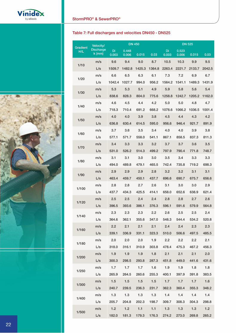
Table 7: Full discharges and velocities DN450 - DN525
Gradient H/L
Velocity/ Discharge
k (mm)
DN 450 DN 525
Di 0.003
0.448 0.006
Di 0.003
0.523 0.0060.015 0.03 0.015 0.03
1/10m/s 9.6 9.4 9.0 8.7 10.5 10.3 9.9 9.5
L/s 1509.7 1482.8 1425.3 1364.8 2263.4 2221.7 2133.7 2042.5
1/20m/s 6.6 6.5 6.3 6.1 7.3 7.2 6.9 6.7
L/s 1042.4 1027.7 994.0 956.2 1564.2 1541.1 1489.3 1431.9
1/30m/s 5.3 5.3 5.1 4.9 5.9 5.8 5.6 5.4
L/s 838.6 828.3 804.0 775.6 1258.8 1242.7 1205.2 1162.0
1/40m/s 4.6 4.5 4.4 4.2 5.0 5.0 4.8 4.7
L/s 718.3 710.4 691.2 668.2 1078.6 1066.2 1036.5 1001.4
1/50m/s 4.0 4.0 3.9 3.8 4.5 4.4 4.3 4.2
L/s 636.8 630.4 614.5 595.0 956.6 946.4 921.7 891.9
1/60m/s 3.7 3.6 3.5 3.4 4.0 4.0 3.9 3.8
L/s 577.1 571.7 558.0 541.1 867.1 858.5 837.3 811.3
1/70m/s 3.4 3.3 3.3 3.2 3.7 3.7 3.6 3.5
L/s 531.0 526.2 514.3 499.2 797.9 790.4 771.8 748.7
1/80m/s 3.1 3.1 3.0 3.0 3.5 3.4 3.3 3.3
L/s 494.0 489.8 479.1 465.5 742.4 735.8 719.2 698.3
1/90m/s 2.9 2.9 2.9 2.8 3.2 3.2 3.1 3.1
L/s 463.4 459.7 450.1 437.7 696.6 690.7 675.7 656.6
1/100m/s 2.8 2.8 2.7 2.6 3.1 3.0 3.0 2.9
L/s 437.7 434.3 425.5 414.1 658.0 652.6 638.9 621.4
1/120m/s 2.5 2.5 2.4 2.4 2.8 2.8 2.7 2.6
L/s 396.5 393.6 386.1 376.3 596.1 591.6 579.9 564.8
1/140m/s 2.3 2.3 2.3 2.2 2.6 2.5 2.5 2.4
L/s 364.6 362.1 355.6 347.0 548.3 544.4 534.2 520.8
1/160m/s 2.2 2.1 2.1 2.1 2.4 2.4 2.3 2.3
L/s 339.1 336.9 331.1 323.3 510.0 506.6 497.5 485.5
1/180m/s 2.0 2.0 2.0 1.9 2.2 2.2 2.2 2.1
L/s 318.0 316.1 310.9 303.8 478.4 475.3 467.2 456.3
1/200m/s 1.9 1.9 1.9 1.8 2.1 2.1 2.1 2.0
L/s 300.3 298.5 293.8 287.3 451.8 449.0 441.6 431.6
1/250m/s 1.7 1.7 1.7 1.6 1.9 1.9 1.8 1.8
L/s 265.9 264.5 260.6 255.3 400.1 397.9 391.8 383.5
1/300m/s 1.5 1.5 1.5 1.5 1.7 1.7 1.7 1.6
L/s 240.7 239.5 236.3 231.7 362.3 360.4 355.3 348.2
1/400m/s 1.3 1.3 1.3 1.3 1.4 1.4 1.4 1.4
L/s 205.7 204.8 202.3 198.7 309.7 308.3 304.3 298.8
1/500m/s 1.2 1.2 1.1 1.1 1.3 1.3 1.3 1.2
L/s 182.0 181.3 179.3 176.3 274.2 273.0 269.8 265.2

23
StormPRO® & SewerPRO®
Table 8: Full discharges and velocities DN600 - DN750
Gradient H/L
Velocity/ Discharge
k (mm)
DN 600 DN 750
Di 0.003
0.596 0.006
Di 0.003
0.731 0.0060.015 0.03 0.015 0.03
1/10m/s 11.4 11.2 10.7 10.3 12.9 12.7 12.2 11.6
L/s 3184.8 3124.5 2998.6 2869.6 5427.6 5320.2 5100.5 4879.5
1/20m/s 7.9 7.8 7.5 7.2 9.0 8.8 8.5 8.2
L/s 2202.4 2168.9 2094.3 2012.8 3757.2 3697.2 3565.8 3425.1
1/30m/s 6.4 6.3 6.1 5.9 7.2 7.1 6.9 6.6
L/s 1773.2 1749.7 1695.5 1634.0 3026.8 2984.5 2888.6 2781.9
1/40m/s 5.4 5.4 5.2 5.0 6.2 6.1 5.9 5.7
L/s 1519.7 1501.6 1458.6 1408.5 2595.3 2562.5 2486.2 2399.0
1/50m/s 4.8 4.8 4.7 4.5 5.5 5.4 5.3 5.1
L/s 1348.1 1333.2 1297.5 1254.9 2302.9 2276.0 2212.4 2138.0
1/60m/s 4.4 4.3 4.2 4.1 5.0 4.9 4.8 4.6
L/s 1222.1 1209.6 1178.8 1141.6 2088.3 2065.5 2010.7 1945.6
1/70m/s 4.0 4.0 3.9 3.8 4.6 4.5 4.4 4.3
L/s 1124.8 1113.8 1086.9 1053.7 1922.3 1902.5 1854.3 1796.2
1/80m/s 3.8 3.7 3.6 3.5 4.3 4.2 4.1 4.0
L/s 1046.6 1037.0 1012.9 982.9 1789.2 1771.6 1728.5 1676.0
1/90m/s 3.5 3.5 3.4 3.3 4.0 4.0 3.9 3.8
L/s 982.2 973.5 951.7 924.4 1679.3 1663.5 1624.5 1576.4
1/100m/s 3.3 3.3 3.2 3.1 3.8 3.7 3.7 3.6
L/s 927.9 920.0 900.1 874.9 1586.6 1572.4 1536.7 1492.3
1/120m/s 3.0 3.0 2.9 2.9 3.4 3.4 3.3 3.2
L/s 840.8 834.2 817.2 795.3 1438.1 1426.1 1395.6 1357.0
1/140m/s 2.8 2.8 2.7 2.6 3.2 3.1 3.1 3.0
L/s 773.5 767.8 752.9 733.6 1323.3 1312.9 1286.2 1252.0
1/160m/s 2.6 2.6 2.5 2.5 2.9 2.9 2.9 2.8
L/s 719.5 714.5 701.3 683.9 1231.2 1222.0 1198.3 1167.5
1/180m/s 2.4 2.4 2.4 2.3 2.8 2.7 2.7 2.6
L/s 675.0 670.5 658.6 642.8 1155.3 1147.0 1125.6 1097.6
1/200m/s 2.3 2.3 2.2 2.2 2.6 2.6 2.5 2.5
L/s 637.5 633.4 622.6 608.1 1091.3 1083.8 1064.3 1038.5
1/250m/s 2.0 2.0 2.0 1.9 2.3 2.3 2.3 2.2
L/s 564.8 561.5 552.6 540.6 967.1 961.0 945.0 923.5
1/300m/s 1.8 1.8 1.8 1.8 2.1 2.1 2.0 2.0
L/s 511.5 508.7 501.2 490.8 876.0 870.9 857.4 838.9
1/400m/s 1.6 1.6 1.5 1.5 1.8 1.8 1.8 1.7
L/s 437.3 435.2 429.5 421.3 749.4 745.5 735.0 720.5
1/500m/s 1.4 1.4 1.4 1.3 1.6 1.6 1.6 1.5
L/s 387.2 385.5 380.8 374.1 663.7 660.6 652.1 640.1

StormPRO® & SewerPRO®
1
24
Table 9: Full discharges and velocities DN450 - DN900
Gradient H/L
Velocity/ Discharge
k (mm)
DN 900
Di 0.003
0.873 0.006 0.015 0.03
1/10m/s 14.4 14.1 13.5 12.9
L/s 8623.3 8446.3 8090.5 7738.1
1/20m/s 10.0 9.8 9.5 9.1
L/s 5974.7 5875.1 5660.8 5434.9
1/30m/s 8.0 7.9 7.7 7.4
L/s 4815.6 4745.3 4588.1 4416.1
1/40m/s 6.9 6.8 6.6 6.4
L/s 4130.6 4075.9 3950.5 3809.5
1/50m/s 6.1 6.0 5.9 5.7
L/s 3666.2 3621.3 3516.5 3396.0
1/60m/s 5.6 5.5 5.3 5.2
L/s 3325.3 3287.2 3196.8 3091.1
1/70m/s 5.1 5.1 4.9 4.8
L/s 3061.7 3028.5 2948.8 2854.3
1/80m/s 4.8 4.7 4.6 4.5
L/s 2850.0 2820.6 2749.3 2663.7
1/90m/s 4.5 4.4 4.3 4.2
L/s 2675.4 2649.0 2584.3 2505.9
1/100m/s 4.2 4.2 4.1 4.0
L/s 2528.1 2504.1 2445.0 2372.5
1/120m/s 3.8 3.8 3.7 3.6
L/s 2292.0 2271.7 2221.0 2157.9
1/140m/s 3.5 3.5 3.4 3.3
L/s 2109.4 2091.8 2047.4 1991.4
1/160m/s 3.3 3.3 3.2 3.1
L/s 1962.9 1947.4 1907.9 1857.4
1/180m/s 3.1 3.1 3.0 2.9
L/s 1842.1 1828.2 1792.5 1746.5
1/200m/s 2.9 2.9 2.8 2.8
L/s 1740.3 1727.7 1695.1 1652.8
1/250m/s 2.6 2.6 2.5 2.5
L/s 1542.6 1532.4 1505.7 1470.3
1/300m/s 2.3 2.3 2.3 2.2
L/s 1397.7 1389.1 1366.4 1335.9
1/400m/s 2.0 2.0 2.0 1.9
L/s 1196.0 1189.5 1172.0 1147.9
1/500m/s 1.8 1.8 1.7 1.7
L/s 1059.7 1054.4 1040.1 1020.2
25
StormPRO® & SewerPRO®
INSTALLATION
Vinidex StormPRO® and SewerPRO® pipes are twin-wall, corrugated polypropylene pipes for non-pressure applications, and can be installed in non-trafficable and trafficable areas, including under road pavements.
This guide is intended to provide general information for the safe installation of Vinidex StormPRO®and SewerPRO® pipes. For more detailed information refer to AS/NZS 2566.2 ‘Buried flexible pipelines: Part 2, Installation’. When designed and installed correctly, Vinidex StormPRO® and SewerPRO® systems will provide continuous service in excess of 100 years.
Flexible PipesVinidex StormPRO®and SewerPRO® are flexible pipes. This means that as vertical loads are applied, the pipe will deflect and take advantage of horizontal soil pressure to provide additional support to the system. The interaction of the pipe and the embedment material means that both play an important role in the structural performance of the pipeline.
Flexible pipes have shown excellent performance in buried applications and have been thoroughly researched in both field installations and laboratory studies.
Well-installed pipes, in which the specified embedment material is placed and compacted to the required level, have characteristically low deflections because the pipe deflection follows the soil settlement.
After initial compaction and settlement, applied vertical loads have very little effect on deflection. The use of flexible pipes in all buried applications including under road pavements is well established in Australia and throughout the world.
Where StormPRO®and SewerPRO® pipes are installed at depths between 0.8m and 6m in normal soils and recommended installation practices are followed there is generally no need for structural design calculations. In these typical installations, deflection can be reliably predicted from a design chart based on the compaction level of the embedment.
For installation conditions at greater depths or in poor soils, a design methodology for flexible pipes is clearly set out in AS/NZS 2566.1 “Buried flexible pipelines. Part 1: Design”. This Standard uses the pipe characteristics and material properties, installation conditions and external loads to predict pipe deflection, strain in the pipe wall and resistance to buckling which are compared against conservative allowable limits.

StormPRO® & SewerPRO®
1
26
Handling & Storage StormPRO®and SewerPRO® pipes are relatively light weight and smaller sizes can be lifted manually. Note that correct PPE and safe lifting practices should always be used. Care should also be taken when pipes are loaded, unloaded, stacked or distributed on sites to avoid damage to the pipe.
When pipes are lifted mechanically, approved and certified web or rope slings should be used. Transport should not have sharp projections which could cause damage to pipes. Pipes should not be dragged along the ground as this can damage the pipe, causing difficulty with jointing and testing.
StormPRO® and SewerPRO® pipes should be stacked on flat firm ground, which has been cleared of debris and hazardous combustible vegetation. Pipes should be laid flat on transverse bearers at least 75mm wide at maximum 1.5m centres.
Pipe sockets should be supported so that the ends are free from loading, with sockets in each layer opposite to the previous layer. Different sizes are best stacked separately. If this is not practical, then stack with the largest pipes at the base. Framed crates
must be stored timber on timber (sizes 150, 225 and 300 only). The height of the pipe stacks should be limited to prevent distortion and excessive ovalisation.
If pipes are to be nested (smaller diameter pipes stored inside larger diameter pipes) for long periods, stacks should not exceed 2m in height.
Trench ExcavationAll trenches are potentially dangerous and proper care should be taken to ensure the stability of the trench wall and the safety of all workers. The trench should not be excavated too far in advance of pipe laying and should be backfilled as soon as possible.
Minimum Trench WidthThe trench width should be as narrow as is practicable, but wide enough to allow adequate compaction of the haunch zone and the making and inspection of joints. AS/NZS 2566.2 sets out the minimum trench dimensions for StormPRO® and SewerPRO® as shown in Table 10.

27
StormPRO® & SewerPRO®
Pipes in ParallelWhere pipes are laid in parallel, the minimum spacings between pipelines are given below.
The trench should be excavated deep enough to allow for the specified grade, the required depth of underlay and the minimum cover.
Nominal Diameter (mm) 150 225 300 375 450 525 600 750 900
Minimum Trench Width
(mm)470 560 745 830 1115 1200 1280 1435 1700
Minimum Depth of Bedding Zone (mm) 100 100 100 100 150 150 150 150 150
Minimum Depth of Overlay Zone (mm) 150 150 150 150 150 150 150 150 200
Table 10: Minimum trench dimensions
Nominal Diameter (mm) 150 225 300 375 450 525 600 750 900
Minimum Spacing
(mm)150 150 200 200 300 300 300 300 350
Table 11: Minimum spacings between parallel pipelines

StormPRO® & SewerPRO®
1
28
Selection of Embedment MaterialEmbedment material for StormPRO® and SewerPRO® pipes should preferably be granular, free-flowing material. This type of embedment material requires less compactive effort to provide support for the pipe and minimises soil settlement.
The table below provides typical gradings for single-size aggregates suitable for use as embedment material for StormPRO® and SewerPRO®.
Where sand is more readily available, a typical sand grading is shown below.
In cases of reduced cover, it may be preferable to use a cement stabilised sand/gravel as the embedment material (including bedding, side support and overlay zones). According to Table L2 of AS/NZS 2566.2, the cement stabilised material should have a cement content of 6-10%, a moisture content of 10%, and have an unconfined compression strength of 1.7MPa, as determined from cylinder specimen at 7 days.
In cases where it is difficult to achieve mechanical compaction of the bedding material, controlled low strength material (CLSM) may be used as an alternative material. CLSM, also known as slurry fill, flowable fill, flowable mortar, soil-cement slurry, unshrinkable fill or controlled density fill, should achieve a compressive strength in the range of 0.6 MPa to 3.0 MPa, depending on cement content.
When placing CLSM, care should be taken to prevent flotation of the pipe by selecting a lift thickness appropriate to the diameter of the pipe, or ballasting the pipe with sandbags. Further details are available in Appendix K of AS/NZS 2566.2.
% PASSING BY MASS
SIEVE SIZE (mm)
Nominal size of single-size
aggregate10mm 7mm 5mm
26.5 - - -
19 - - -
13.2 100 - -
9.5 85-100 100
6.7 - 85-100 100
4.75 0-20 - 85-100
2.36 0-5 0-20 0-40
0.075 0-2 0-2 0-2
Table 12: Typical aggregate grading
SIEVE SIZE (mm) % PASSING BY MASS
4.75 100
2.36 90-100
1.18 85-100
0.6 70-100
0.3 50-100
0.15 0-40
0.075 0-5
Table 13: Typical sand grading

29
StormPRO® & SewerPRO®
Placing and Compacting of Embedment MaterialThe embedment material should be placed and graded to invert level, and compacted to a minimum 95% Modified Maximum Dry Density or 70% Density Index, depending on the selected material. In conditions where the trench bottom is wet, soft or irregular, it may be necessary to first stabilise, fill and level, and compact the base. Place and compact material in the pipe bedding zone to minimum depth of 75mm beneath the pipe.
Side support and overlay material should be placed in a manner to ensure:
a. uniform distribution and compaction of embedment material, especially under the haunches of the pipe;
b. the material relative compaction is consistent with design;
c. pipe distortion is minimized;d. the pipe is not damaged; ande. the specified pipe alignment,
level and grade is maintained
In order to ensure uniform support along the pipe barrel, a small indentation should be excavated in the pipe bedding zone to accommodate the pipe sockets.
The pipe side support material should be placed evenly on both sides of the pipeline and compacted such that relative compaction is consistent with design. Side support material should be worked under the sides of the pipe to minimise voids and provide maximum pipe haunching, taking care to minimise distortion of the pipe and maintain alignment and grade.
The pipe overlay material should be levelled and compacted in layers, to a minimum height of 150mm above the crown of the pipe, or as specified.
Cutting of PipesDN150 to DN600 StormPRO® and SewerPRO® pipes may be cut anywhere along their length as required, always ensuring that safe work practices are followed. The cut should be made in the valley between the corrugations at right angles to the axis of the pipe. No end treatment or chamfer is required.
StormPRO® and SewerPRO® pipes can be safely cut using any saw suitable for cutting timber. This can be a manual or powered saw.
Due to the reduced spigot diameter, cutting of DN750 and DN900 StormPRO® and SewerPRO® pipe is not recommended unless absolutely necessary. Special slip couplings and rubber rings are required to connect cut DN750 and DN900 StormPRO® and SewerPRO® pipe.

StormPRO® & SewerPRO®
1
30
Jointing InstructionsThe following procedure is recommended when jointing StormPRO® and SewerPRO® rubber ring jointed pipes:
1. Clean the pipe socket and spigot end, making sure both are free of any dirt and grit. Any foreign matter trapped in the joint will compromise joint performance and leak-tightness of the system.
2. For DN150 – DN600 - Install the rubber ring by stretching it over the spigot so that it seats between the first and second corrugations from pipe spigot end. For DN750 and DN900 pipes – Install two rubber rings, one in the valley between the first and second corrugations and one in the adjacent valley between the second and third corrugations from the spigot end.
3. Ensure rubber rings are evenly fitted by running fingers around the full circumference of the pipe.
4. Apply a generous quantity of Vinidex jointing lubricant to the inside of the receiving socket. Do not lubricate the rubber ring or the valley under the rubber ring. Avoid getting lubricant under the rubber ring. This will ensure that the ring does not pick up dirt and introduce contaminants to the joint or become displaced during jointing.
HINT: To further minimize the risk of introducing grit from the embedment material into the joint, a small piece of rubber mat, poly tarp or equivalent can be temporarily placed under the socket/spigot during joint assembly.
5. Insert the leading edge of the spigot into the receiving socket. It is essential that pipes are in a straight line before attempting to make the joint. Double check that the ring and spigot is free from any grit or embedment material so as not to compromise the joint.
6. Do not apply jointing force directly to the socket. Insert a short stub of pipe in the opposite socket. The short stub can be an off-cut, 50mm longer than the socket, and can be re-used.
7. Apply even jointing force. Subject to pipe diameter and local conditions, use a crowbar (see Note) to push on a timber block on the end of the short pipe.
8. Push home the pipe until the spigot end comes into contact with the inner wall of the socket.
NOTE: The jointing force required increases with the nominal diameter of the pipe. A leverage tool such as a crowbar is generally sufficient for StormPRO® and SewerPRO® pipes up to 375mm nominal diameter. For larger sizes, mechanical assistance is required. Where applying a jointing force is not practical, consideration should be given to the use of come-along or winch and rope devices.

31
StormPRO® & SewerPRO®
Angular DeflectionThe pipe may be deflected at the joint after jointing has been completed. Any deflection should be limited to a maximum of 1º.
Witness MarkThe rubber ring is held in position by the corrugations as shown in the diagrams below. When the joint is assembled, the inner walls of the pipe butt together so it is not necessary to joint to a witness mark in the same way as it is for pipe joints designed with a laying gap.
Depending on manufacturing tolerances, a witness mark on the crest of the 5th rib for sizes DN150 to DN300 and on the crest of the 4th rib for sizes DN375 to DN900 will be either wholly within the socket, or just visible at the mouth at the completion of jointing.
Internal LiningWhen the StormPRO® and SewerPRO® pipes are pushed fully home during assembly, the spigot end and the internal lining at the back of the socket are generally in contact. However, due to manufacturing tolerances or where there is angular deflection at the joint a small gap may sometimes be observed. This has no effect on the sealing capability of the joint. To reduce this gap when cutting pipe, ensure the cut is clean and even throughout.
BackfillingWhere the finished surface is not to be paved, and surface settlement is not considered critical, ordinary fill material is suitable up to the finished surface. Under pavements where settlement of the fill material is to be controlled, a fill material that can be compacted to the required density should be used.
Trench fill should be placed on the pipe overlay and compacted as specified but generally not in layers in excess of 300mm. Complete the backfilling operation to finished surface level.
Allowable CoverMinimum cover in Table F reflects industry standards for various design load cases.
Table 14: Minimum depth of cover over pipe
Loading Condition Minimum Cover (m)
Not subject to vehicular loading
0.30
Land zoned for agricultural use
0.60
Subject to vehicular loading:(a) no carriageway(b) sealed carriageways(c) unsealed carriageways
0.450.600.75
Pipelines in embankments or subject to construction equipment loads
0.75

StormPRO® & SewerPRO®
1
32
Construction LoadsDuring construction, consideration of loading during placement and compaction of fill around the pipe and any other construction loading is critical. Care must be taken to ensure that any construction loading from trench compaction and road construction equipment does not overload the pipe.
The following minimum depths of compacted fill over the pipe apply for the placement and compaction of fill around of StormPRO® and SewerPRO®.
FlotationThe possibility of pipe flotation exists when StormPRO® and SewerPRO® are installed in areas which will be inundated, such as creek crossings, flood plains and high groundwater areas. To prevent flotation, a minimum cover equivalent to 75% of the nominal diameter is required.
Table 15: Minimum depths of compacted fill over StormPRO® and SewerPRO® for construction loads
Construction Load
Minimum compacted fill over StormPRO® and SewerPRO®
Pedestrian vibrating plate 200mm
Vibratory rammer (up to 75kg) 250mm
Vibratory trench roller (up to 2t) 250mm
Vibratory smooth drum roller (7t) 500mm
Truck and dog trailer 500mm
25 tonne excavator and 580 mm compaction wheel acting separately
1,000mm

33
StormPRO® & SewerPRO®
Concrete EncasementWhere concrete encasement is required, StormPRO® and SewerPRO® pipes should be laid to the correct alignment and grade, supported on hessian bags filled with stabilised sand or on concrete blocks or cradles. The concrete surround should be placed so as to provide uniform and continuous support around the entire circumference of the pipe.
StormPRO® and SewerPRO® joints for concrete encasement should be made with an additional rubber ring. For pipe sizes up to and including DN300, a gap should be left and the extra ring placed in the valley between the third and fourth corrugations from the spigot end. For sizes DN375 and greater, the second ring should be placed adjacent to the first ring in the valley between the second and third corrugations. DN750 and DN900 have rings in the first two valleys as usual. Table 16 outlines placement of additional rings.
The completed joint should also be sealed with tape to prevent concrete entering the socket during encasement.
The pipe shall be restrained and care taken to prevent movement, misalignment, distortion and / or flotation during the encasement process.
Table 16: Placement of additional rubber ring for concrete encasement
DN150 to DN300 DN375 to DN600 DN750 to DN900
PIPE JOINT SEALED WITH TAPE
FOR ALL SIZES

StormPRO® & SewerPRO®
1
34
Connection to StructuresStormPRO® and SewerPRO® pipes may generally be connected to rigid structures such as pits, headwalls and endwalls, both pre-cast and cast in situ. StormPRO® and SewerPRO® pipes have sufficient flexibility and strain tolerance to accommodate differential settlement at the interface. The figure below shows a typical entry or exit to a concrete structure.
Above-Ground InstallationFor above-ground applications, StormPRO® must be adequately supported in order to prevent sagging and excessive distortion.
Clamp, saddle, angle, spring or other standard types of supports and hangers may be used where necessary. Pipe hangers should not be overtightened.
StormPRO® should be supported at regular intervals as detailed in the table below, always with one support located directly behind the socket. These support spacings are based on StormPRO® carrying water at 20°C.
Note that the hydrophilic seal is required only where a waterproof seal is critical. When required, use Hydrotite DSS0220 or equivalent.
Note that where temperatures in excess of 20°C are likely, the support spacing should be reduced.
The supports should provide a bearing surface of 120° under the base of the pipes and should be at least two corrugations wide. The pipes should be protected from damage at the supports with the provision of a membrane of PE, PVC or rubber. Table J refers to the maximum support spacings for above-ground installations.
Nominal Diameter (mm)
150 225 300 375 450 525 600 750 900
Minimum Horizontal Support Spacing (m)
1.25 1.60 1.90 2.15 2.50 2.75 3.00 3.00 3.00
Table 17: Maxiumum support spacings
(Optional for StormPRO)

35
StormPRO® & SewerPRO®
Stormwater ConnectionsThe Vinidex PROgrommet range ofstormwater service connections provide 100mm and 150mm diameter connections to StormPRO® pipe up to 900mm nominal diameter. The following procedure is recommended when installing the PROgrommet:
1. Drill hole in StormPRO® pipe using the PROsaw. Hole centre must be located in the valley between corrugations.
2. Inspect marking on PROgrommet to ensure the correct size for selected StormPRO® pipe.
3. Present PROgrommet to hole with PROgrommet flange to the inside and locating wings to the outside of the StormPRO® pipe.
4. Squash the PROgrommet by hand whereby the two locating wings align in the centre.
5. With the flattened PROgrommet, form a “C” shape and offer it to the prepared hole.
6. Position locating wings in the valley of the StormPRO® pipe profile.
7. Apply Vinidex Lubricant to the inside diameter of the PRO stopper. Insert PRO stopper into PROgrommet
8. Cut lead-in chamfer on pipe which is to be offered to PRO stopper.
9. Mark a line on pipe showing the required insertion depth.
10. Dry, degrease and prime the branch pipe spigot and the PRO stopper socket with a lint-free cloth dampened with Vinidex priming fluid.
11. Apply a thin even coat of Vinidex Type N solvent cement to the internal surface of the PRO stopper socket first, then apply a heavier, even coat of Vinidex Type N solvent cement up to the witness mark on the branch pipe spigot.
12. Insert the branch pipe spigot home to the full depth of the PRO stopper socket
13. Hold the joint against movement and rejection of the spigot for a minimum of 30 seconds, then wipe off excess solvent cement from the outside of the joint.

StormPRO® & SewerPRO®
1
36
The following procedure is recommended when installing PROsaddles:
1. Drill a hole in the StormPRO® pipe at the required location as per PROsaw user instructions – pilot drill must be positioned in the valley between corrugations.
2. Remove the access cap. Inspect the label on the PROsaddle to ensure the correct size for the selected StormPRO® pipe.
3. Apply a thin bead of Butyl Mastic along the raised sealing faces of the gasket and in the holes (top and bottom).
4. Place the gasket and saddle in position.
5. Secure with the four fasteners provided – do not overtighten.
6. Before joining the branch pipe to the saddle, check that the branch pipe has been cut square and all the burrs are removed from the inside and outside edge. Remove all dirt, swarf, and moisture from the branch pipe and the PROsaddle socket.
7. Mark the spigot of the branch pipe with a witness mark at a distance equal to the internal depth of the PROsaddle socket.
8. Dry, degrease and prime the branch pipe spigot and the PROsaddle socket with a lint-free cloth dampened with Vinidex priming fluid.
9. Apply a thin even coat of Vinidex Type N solvent cement to the internal surface of the PROsaddle socket first, then apply a heavier, even coat of Vinidex Type N solvent cement up to the witness mark on the branch pipe spigot.
10. Insert the branch pipe spigot home to the full depth of the PRO saddle socket
11. Hold the joint against movement and rejection of the spigot for a minimum of 30 seconds, then wipe off excess solvent cement from the outside of the joint.
Embedment material should be placed around the branch pipe and saddle, and compacted to a minimum 90% Modified Maximum Dry Density or 60% Density Index, depending on the selected material.The branch pipe support material should be placed evenly around the pipe and compacted such that relative compaction is consistent with design.

37
StormPRO® & SewerPRO®
Field TestingLeakage testing is carried out to identify installation faults and sources of infiltration and exfiltration in pipelines which are required to be water-tight such as sewerage systems. Leakage testing is generally not required for stormwater drains.
It is advisable to begin testing early in the pipeline installation to confirm adequacy of laying procedures and, where appropriate, to increase the length tested progressively as experience is gained.
AS/NZS 2566.2 specifies detailed procedures for leakage testing using hydrostatic testing, air or vacuum testing or infiltration testing of non-pressure pipelines. These methods are summarised below. Notwithstanding this, leakage testing should be carried out in accordance with local authority requirements.
Method 1: Hydrostatic TestFill the pipeline with water and pressurise to not less than 20kPa at the highest point of the section being tested, but not greater than 60kPa at the lowest point of the test section. Maintain the test pressure for at least 2 hours by adding measured volumes of water if required. Each joint should be carefully examined visually for leaks, and any defects should be repaired. The pipeline section is deemed satisfactory if the make-up volume is less that 0.5L per hour per metre length per metre diameter. After any repairs, the pipeline should be re-tested.
Method 2: Air TestIntroduce air slowly by suitable means until a pressure of 25kPa is obtained. Maintain for a period of at least 3 minutes. If no leaks are observed after 3 minutes, shut off the air supply. If the pressure of air contained in the pipes under test does not fall below 18kPa within the time period specified in the table below, the pipeline shall be considered satisfactory.
If, however, the pressure is not maintained within the specified limits, reintroduce the air and examine the pipeline for leaks by pouring a concentrated solution of soft soap and water over the joints and fittings. Identify and repair any leaks. After any repairs, the pipeline should be re-tested.
Method 3: Vacuum TestApply a vacuum until a negative pressure of 25 kPa is obtained. Maintain for a period of at least 3 minutes. If no leaks are observed after 3 minutes, isolate the test section from the vacuum pump. Monitor the pressure for the time specified in the table below. If the vacuum does not drop below 18 kPa within the specified time period, the pipeline shall be considered satisfactory. Where the pipeline section fails the test, re-apply the vacuum and examine the pipeline for leaks. Identify and repair any leaks. After any repairs, the pipeline should be re-tested.

StormPRO® & SewerPRO®
1
38
Method 4: Infiltration TestWhere there is a free standing water table at a height of at least 1.5m above the test section, an infiltration test can be carried out. Observe the pipe for 24 hours. Where infiltration is detected, the leak should be identified and repaired.
Water Jet CleaningHigh-pressure water jet cleaning of internal pipeline surfaces is common, but if not properly managed, water emitted under high-pressure through a jet nozzle has the potential to damage any pipe surface, including those manufactured from plastics, metallic, ceramic and concrete materials.
PIPA Industry Guidelines POP205 provides information based on experience and research, as to the maximum pressures that may be used to avoid damage to StormPRO® and SewerPRO® pipes. The guidelines can be downloaded at http://www.pipa.com.au/documents/water-jet-cleaning-plastics-pipes.
Minimum Test Duration (min)
DN Test Length (m) -50
Test Length (m) -100
Test Length (m) -150
Test Length (m) -200
Test Length (m) -250
150 3 3 3 5 6
225 4 5 8 10 13
300 6 9 14 18 23
375 7 14 22 29 36
450 10 21 31 41 52
525 14 28 42 56 70
600 18 37 55 73 92
750 29 57 86 115 143
900 41 83 124 165 207
Table 18: Minimum time intervals for 7kPa pressure change in air and vacuum test

39
StormPRO® & SewerPRO®
CUT-INS & REPAIRS
Cut-InsTo cut into an existing buried StormPRO® or SewerPRO® pipeline and install a socketed junction or other socketed fitting, the following procedure should be adopted:
1. Expose the existing pipe and cut out a length equal to the effective length of the fitting, plus approximately 600mm.
2. Connect 300mm long short pipes to the junction sockets and fit rubber rings to the spigot ends of the short pipes.
3. Fit slip couplings to the cut ends of the existing pipe and install junction.
RepairsIf StormPRO® or SewerPRO® is damaged, the repair method will depend on the nature and severity of the damage. Table K below provides guidance on the most suitable method relative to the extent of damage.
Contact Vinidex for a range of repair clamps and fittings for StormPRO® and SewerPRO® pipes.
Standard and Slip CouplingsStandard socket/socket couplings and slip couplings are available in all sizes. Refer product catalogue for further information.
Table 19: Suitable methods of pipe repair
EXTENT OF DAMAGE REPAIR METHOD
INTERNAL Minor damage to inner wall (no penetration) No repair required
Penetration of the inner wall Internal repair sleeve requiredEXTERNAL Minor damage to outer wall (no
penetration of the outer corrugated wall)
No repair required
Minor damage to outer wall (penetration of the outer corrugated wall)
External repair sleeve required
Penetration of both inner and outer walls
Cut, remove and replace affected section of pipe

Vinidex Pty LimitedABN 42 000 664 942
HEAD OFFICELevel 4, 26 College Street Darlinghurst NSW 2010 PO Box 747, Darlinghurst NSW 1300
CUSTOMER SERVICEPhone: 13 11 69 Fax: 13 24 43
Email: [email protected] Web: www.vinidex.com.au
VIN264- 20190724
Limitation of LiabilityThis product catalogue has been compiled by Vinidex Pty Limited (“the Company”) to promote better understanding of the technical aspects of the Company’s products to assist users in obtaining from them the best possible performance. The product catalogue is supplied subject to acknowledgement of the following conditions: 1 The product catalogue is protected by copyright and may not be copied or reproduced in any form or by any means in whole or in part without prior consent in writing by the Company. 2 Product specifications, usage data and advisory information may change from time to time with advances in research and field experience. The Company reserves the right to make such changes at any time without further notice. 3 Correct usage of the Company’s products involves engineering judgements, which can not be properly made without full knowledge of all the conditions pertaining to each specific installation. The Company expressly disclaims all and any liability to any person whether supplied with this publication or not in respect of anything and all of the consequences of anything done or omitted to be done by any such person in reliance whether whole or part of the contents of this publication. 4 No offer to trade, nor any conditions of trading, are expressed or implied by the issue of content of this product catalogue. Nothing herein shall override the Company’s Condition of Sale, which may be obtained from the Registered Office or any Sales Office of the Company. 5 This product catalogue is and shall remain the property of the Company, and shall be surrendered on demand to the Company. 6 Information supplied in this product catalogue does not override a job specification, where such conflict arises; consult the authority supervising the job. © Copyright Vinidex Pty Limited.