Embed Size (px)
Citation preview
i
Waste Discharge Identification Number (WDID):
STORM WATER POLLUTION PREVENTION PLAN
for
Angora Trails Restoration
USDA Forest Service, Lake Tahoe Basin Management Unit
Legally Responsible Person (LRP)
Nancy Gibson, Forest Supervisor
Lake Tahoe Basin Management Unit
530-543-2600
Approved Signatory
Jordan Burge, P.E. Lake Tahoe Basin Management Unit
Office: 530-543-2670
Jordan Burge, QSD Date
SWPPP Date: April 2, 2013

ii
iii
Contents I. Introduction and Certifications .................................................................................................................. 1
I.A. SWPPP Objectives ............................................................................................................................... 1
I.B. SWPPP Implementation Schedule ...................................................................................................... 1
I.C. Permit Registration Documents .......................................................................................................... 1
I.D. Certification and Training Requirements ........................................................................................... 3
I.D.1. Qualified SWPPP Developer ........................................................................................................ 3
I.D.2. SWPPP Certification and Approval .............................................................................................. 3
I.D.3. Qualified SWPPP Practitioner ...................................................................................................... 4
I.D.4. Legally Responsible Person .......................................................................................................... 6
I.E. Contractor List ..................................................................................................................................... 7
I.F. Emergency contact person and 24-hour phone number .................................................................... 7
I.G. SWPPP Availability and Public Records Access ................................................................................... 7
I.H. Required Changes ............................................................................................................................... 7
II. Project Information ................................................................................................................................... 9
II.A. Project Description, site address and driving directions ................................................................... 9
II.A.1. Project Description ..................................................................................................................... 9
II.A.2. Site Location ............................................................................................................................. 13
II.B. WDID ................................................................................................................................................ 13
II.C. Construction Schedule ..................................................................................................................... 13
II.D. Potential Construction Site Pollutants of Concern and Sources ..................................................... 14
II.E. Site Location Map(s) ........................................................................................................................ 14
III. Best Management Practices .................................................................................................................. 17
III.A. Site Management Narrative ........................................................................................................... 17
III.B. Sediment and Erosion/Stabilization Control Narrative .................................................................. 19
III.B.1. Erosion Control ........................................................................................................................ 19
III.B.2. Sediment Control ..................................................................................................................... 22
III.C. Non-Storm water and Material Management Narrative ................................................................ 23
III.D. Dewatering and Diversion Plan Narrative ...................................................................................... 25
III.E. Active Treatment System Plan Narrative ........................................................................................ 25
III.F. Post-Construction Storm Water Management Measures Narrative .............................................. 25
III.G. Schedule for BMP Implementation ................................................................................................ 25
iv
III.H. BMP and Disturbed Soil Area maps ................................................................................................ 26
IV. BMP Inspection, maintenance and Rain Event Action Plans ................................................................. 41
IV.A. BMP Inspection and Maintenance Narrative ................................................................................. 41
IV.B. Rain Event Action Plan Narrative .................................................................................................... 41
V. Construction Site Monitoring and Reporting Plan (CSMRP) ................................................................... 43
V.A. Purpose ............................................................................................................................................ 43
V.B. Visual Monitoring ............................................................................................................................ 43
V.C. Water Quality Sampling and Analysis .............................................................................................. 44
V.D. Watershed Monitoring Option ........................................................................................................ 45
V.E. Quality Assurance and Quality Control ............................................................................................ 45
V.F. Reporting Requirements and Records Retention ............................................................................ 45
V.F.1. Record Keeping ......................................................................................................................... 45
V.G. Non-Compliance Reporting ............................................................................................................. 45
V.G.1. 24-Hour Reporting .................................................................................................................... 45
V.G.2. Planned Changes ...................................................................................................................... 46
V.G.3. Anticipated Noncompliance ..................................................................................................... 46
V.H. Annual Report ................................................................................................................................. 46
V.I. Final Report ....................................................................................................................................... 47
Appendices ..................................................................................................................................................... i
Appendix A – SWPPP Amendment Forms ...................................................................................................... i
Appendix B – CASQA BMP Standard Specifications ....................................................................................... i
Appendix C – Engineering Plans and Specifications (EPS) .............................................................................. i
Appendix D - Visual Monitoring/BMP Inspection Form ................................................................................. i
Appendix E - Rain Event Action Plan Template .............................................................................................. i
Appendix F – Permit Documents .................................................................................................................... i
Appendix G – Training Logs ............................................................................................................................ i
Appendix H – Prohibition Exemption Information ......................................................................................... i

v
1
I. Introduction and Certifications
I.A. SWPPP Objectives
This SWPPP has been developed for the Angora Trails Restoration Project to comply with the
requirements to implement BMPs to achieve compliance with effluent limits and receiving
water objectives as directed by the Construction General Permit for the Lake Tahoe Hydrologic
Unit (Board Order R6T-2011-0019, NPDES No. CAG616002). This SWPPP has been developed
and will be amended, when necessary, to meet the following objectives:
1. Identify, construct, implement and maintain BMPs to reduce or eliminate pollutants in
storm water discharges and authorized non-storm water discharges from construction
sites.
2. Identify pollutant sources including sediment sources that may affect the quality of storm
water discharges associated with construction activity.
3. Identify non-storm water discharges.
4. Identify all effluent discharge outfall locations, sampling and analysis strategy and
protocols, and a sampling schedule for discharges from the identified outfalls from the
project area.
I.B. SWPPP Implementation Schedule
Construction on Angora trails will commence as soon as site conditions allow and all permits
are in place. The entire project will last approximately 14 weeks. The most important and
effective BMP that will be utilized will be scheduling. Because trail construction is primarily
linear, permanent BMPs will be installed and constructed daily. The crews will not disturb more
soil than what can be permanently stabilized that day. This will include a compacted, outsloped
trail surface with installed drainage features.
All ground disturbing activities in or near riparian zones will likely occur in August at the
earliest, when groundwater levels are low. These activities will be completed by October 1, and
all winterization and permanent stabilization BMPs will be implemented by October 15. See
Section III.G, Schedule for BMP Implementation, for more information.
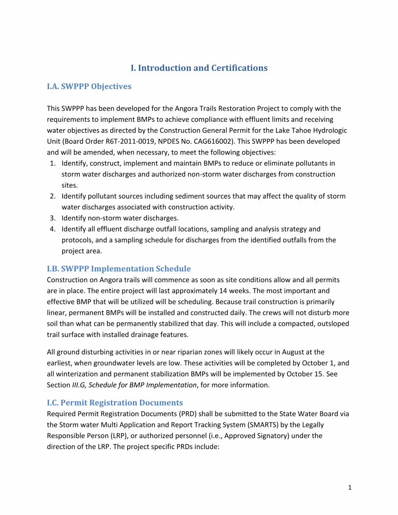
I.C. Permit Registration Documents
Required Permit Registration Documents (PRD) shall be submitted to the State Water Board via
the Storm water Multi Application and Report Tracking System (SMARTS) by the Legally
Responsible Person (LRP), or authorized personnel (i.e., Approved Signatory) under the
direction of the LRP. The project specific PRDs include:

2
Notice of Intent (NOI);
Site Maps;
Annual Fee;
Signed Certification Statement (LRP Certification is provided electronically with SMARTS
PRD submittal); and
SWPPP
Site Maps can be found on Figure 1, Figure 2, and Appendix H. A copy of all other submitted
PRDs shall be kept in Appendix F, along with the Waste Discharge Identification (WDID)
confirmation.
3
I.D. Certification and Training Requirements
The SWPPP must be prepared, signed and certified by a QSD. Additionally, the SWPPP must
identify the QSP.
I.D.1. Qualified SWPPP Developer
The QSD shall certify and amend the SWPPP. Jordan Burge is the QSD and meets the
certification requirement of Section VII.B.1 of the Construction General Permit based on:
Registered Professional Civil Engineer, State of California # 78252
Qualified SWPPP Developer (QSD) Registration # 01217
The QSD has received the following training:
California Construction General Permit Training, June 2011
I.D.2. SWPPP Certification and Approval
Qualified SWPPP Developer
Project Name: Angora Trails Restoration
“This Stormwater Pollution Prevention Plan and Appendices were prepared under my direction
to meet the requirements of the Construction General Permit for Storm Water discharge in the
Lake Tahoe Hydrologic Unit (Board Order No R6T-2001-0019). I certify that I am a Qualified
SWPPP Developer in good standing as of the data signed below.”
_______________________ ____________
QSD Signature Date
4
I.D.3. Qualified SWPPP Practitioner
The QSP shall meet the certification requirement of Section VII.B.3 of the Construction General
Permit. John Hidy will be the project manager and QSP for this project. He is a certified CESSWI
and has passed the required QSP exam. John Hidy’s information:
CASQA QSP Certificate Number: 22519
California Construction General Permit Training, June 2011
The QSP shall have primary responsibility and significant authority for the implementation,
maintenance, and inspection/monitoring of SWPPP requirements. The QSP will be available at
all times throughout the duration of the project.
Duties of the QSP include but are not limited to:
Ensuring full compliance with the SWPPP and the Construction General Permit
Implementing all elements of the SWPPP, including but not limited to:
o Ensuring all BMPs are implemented, inspected and properly maintained;
o Preparing weekly, pre-storm, during storm, and post-storm BMP inspection
reports;
o Performing non-storm water visual observations and inspections;
o Performing non-storm water sampling and analysis, as required;
o Performing routine inspections and observations;
o Implementing non-storm water management, and materials and waste
management activities such as: monitoring discharges; general Site clean-up;
vehicle and equipment cleaning, fueling and maintenance; spill control; ensuring
that no materials other than storm water are discharged in quantities which will
have an adverse effect on receiving waters; etc.;
o Conducting pre-storm inspections for qualifying storm events;
o Conducting daily inspections during qualifying storm events;
o Conducting post-storm inspections for qualifying storm events;
o Monitoring weather forecasts for both likely precipitation events and qualifying
rain events;
o Preparing and implementing Rain Event Action Plans for likely precipitation
events;
o Submitting numeric effluent limitations (NELs) exceedence data, including storm
water effluent limits and receiving water limits and reports to the QSD and
Approved Signatory. Following receipt of QSD’s and/or Approved Signatory’s
approval, QSP shall upload the NEL exceedence data or report to the SWRCB’s
SMARTS;
o Ensuring elimination of all unauthorized discharges;

5
o Mobilizing crews in order to make immediate repairs to the control measures;
o Notifying the LRP or Authorized Signatory immediately of off-site discharges or
other non-compliance events;
o Submitting Notices of Discharge and reports of Illicit Connections or Illegal
Discharges;
o Preparing Annual Report summarizing corrective actions, sampling and analyses,
and any corrective actions not implemented.
The QSP may delegate the inspections and activities to an appropriately trained employee, but
shall ensure adequacy and adequate deployment.
The QSP shall also be responsible for providing training of project personnel on SWPPP
implementation procedures. Before construction operations commence the QSP will conduct
an on-site training with project personnel to review the SWPPP, construction operations and
necessary BMPs. Additionally, trainings will be held as necessary on specific tasks as the project
progresses and tasks change. Training logs (Appendix G) will be filled out for each training and
kept with the SWPPP.
6
I.D.4. Legally Responsible Person
Approval and Certification of the Storm Water Pollution Prevention Plan
Project name: Angora Trails Restoration
“I certify that this document and all Appendices were prepared under my direction in accordance with a
system designed to ensure that qualified personnel properly gather and evaluated the information
submitted. Based on my inquiry of the person or persons who manage the system or those persons
directly responsible for gathering the information, to the best of my knowledge and belief, the
information submitted is true, accurate, and complete. I am aware that there are significant penalties
for submitting false information.”
Nancy Gibson Lake Tahoe Basin Management Unit
Legally Responsible Person Organization
LRP Signature Date
Forest Supervisor 530-543-2600
Title Telephone Number

7
I.E. Contractor List
All construction covered under this SWPPP will be completed by internal Forest Service crews.
I.F. Emergency contact person and 24-hour phone number
Owner: US Forest Service, LTBMU
35 College Drive
South Lake Tahoe, CA 96150
530-543-2600
Project Manager: John Hidy, Trail Project Leader
QSP
Office: 530-543-2650
Cell: 760-920-2774
Alternate: Jordan Burge, P.E.
QSD
Office: 530-543-2670
Hazardous Spill: Genevieve Villemaire
Forest Spill Coordinator, LTBMU
530-543-2783
I.G. SWPPP Availability and Public Records Access
A copy of the SWPPP will be kept on the project site at all times. Additionally, the SWPPP will be
available for view in the SMARTS database.
I.H. Required Changes
The SWPPP shall be maintained such that it reflects the actual site conditions for the duration
of the project. This will require the QSD to amend the SWPPP whenever a qualifying change is
made. The SWPPP shall be revised when:
There is a change in construction, or operations, which may affect the discharge or
pollutants to surface waters or ground waters as determined using the criteria
outlined under section V.G.2. “Planned Changes;”
There is an increase in the disturbed acreage;
BMPs do not meet the objectives of reducing or eliminating pollutants in storm
water discharges;
8
There is a General Permit violation. If the LRWQCB determines that a Permit
violation has occurred, the SWPPP shall be amended and implemented within 72
hours of notification, or as soon as additional materials can be obtained, if needed.
When deemed necessary by the QSD or project engineer.
The following items shall be included in each amendment:
Who requested the amendment;
The location of proposed change;
The reason for change;
The original BMP proposed, if any;
The new BMP proposed
Approved amendments shall be uploaded into the SMARTS database and inserted into the
appropriate section of the SWPPP or Appendix and a SWPPP Amendment Certification shall be
kept with the SWPPP. The SWPPP text shall be revised, replaced, and/or hand-annotated as
necessary to properly convey the amendment. Additionally, LRWQCB staff will be notified by
email of all SWPPP amendments once uploaded into SMARTS.
A blank copy of the SWPPP Amendment Certification and Approval form is in Appendix A. A
SWPPP amendment log will be kept on-site with the SWPPP during construction operations.
The SWPPP amendment log form can be found in Appendix A.
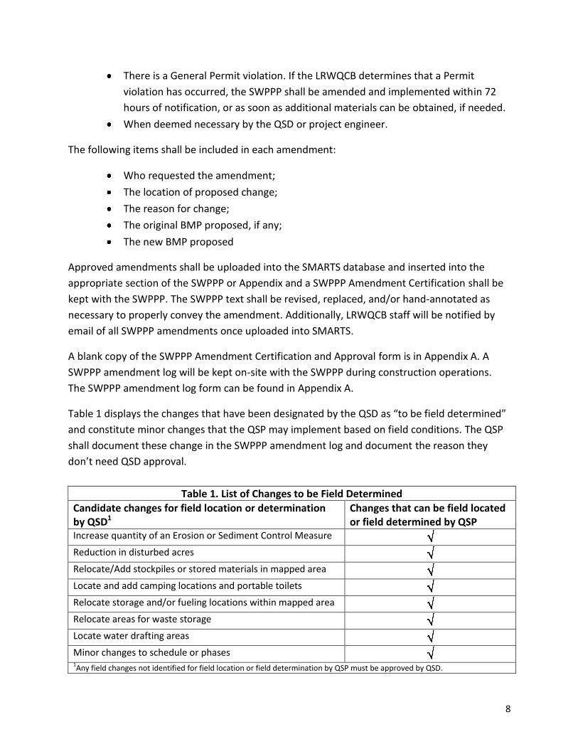
Table 1 displays the changes that have been designated by the QSD as “to be field determined”
and constitute minor changes that the QSP may implement based on field conditions. The QSP
shall document these change in the SWPPP amendment log and document the reason they
don’t need QSD approval.
Table 1. List of Changes to be Field Determined
Candidate changes for field location or determination by QSD1
Changes that can be field located or field determined by QSP
Increase quantity of an Erosion or Sediment Control Measure
Reduction in disturbed acres
Relocate/Add stockpiles or stored materials in mapped area
Locate and add camping locations and portable toilets
Relocate storage and/or fueling locations within mapped area
Relocate areas for waste storage
Locate water drafting areas
Minor changes to schedule or phases 1Any field changes not identified for field location or field determination by QSP must be approved by QSD.
9
II. Project Information
II.A. Project Description, site address and driving directions
II.A.1. Project Description
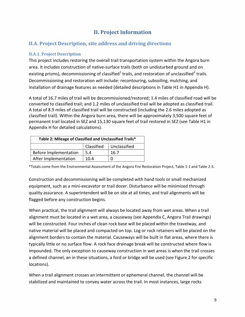
This project includes restoring the overall trail transportation system within the Angora burn
area. It includes construction of native-surface trails (both on undisturbed ground and on
existing prisms), decommissioning of classified1 trails, and restoration of unclassified2 trails.
Decommissioning and restoration will include: recontouring, subsoiling, mulching, and
installation of drainage features as needed (detailed descriptions in Table H1 in Appendix H).
A total of 16.7 miles of trail will be decommissioned/restored; 1.4 miles of classified road will be converted to classified trail; and 1.2 miles of unclassified trail will be adopted as classified trail. A total of 8.9 miles of classified trail will be constructed (including the 2.6 miles adopted as classified trail). Within the Angora burn area, there will be approximately 3,500 square feet of permanent trail located in SEZ and 15,130 square feet of trail restored in SEZ (see Table H1 in Appendix H for detailed calculations).
Table 2: Mileage of Classified and Unclassified Trails*
Classified Unclassified
Before Implementation 5.4 16.7
After Implementation 10.4 0
*Totals come from the Environmental Assessment of the Angora Fire Restoration Project, Table 1-1 and Table 2-3.
Construction and decommissioning will be completed with hand tools or small mechanized
equipment, such as a mini-excavator or trail dozer. Disturbance will be minimized through
quality assurance. A superintendent will be on site at all times, and trail alignments will be
flagged before any construction begins.
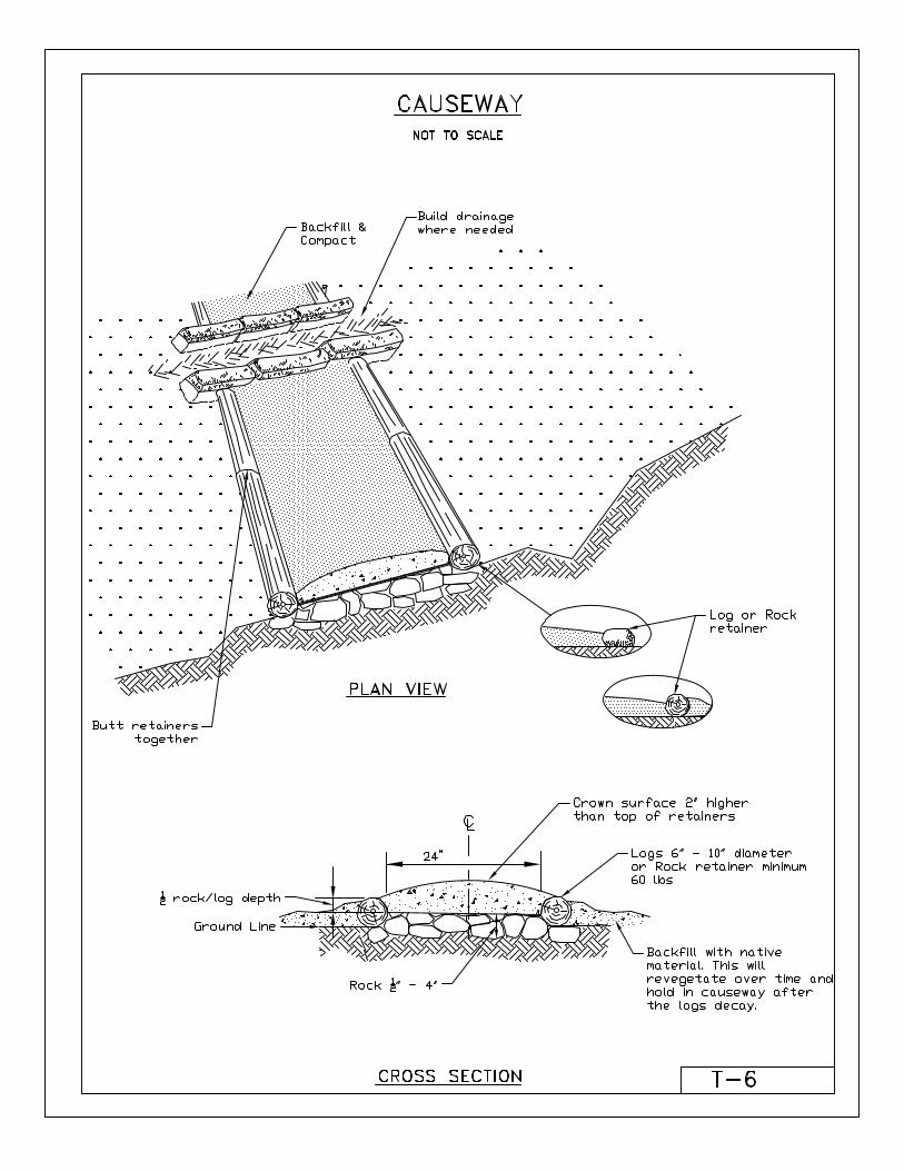
When practical, the trail alignment will always be located away from wet areas. When a trail
alignment must be located in a wet area, a causeway (see Appendix C, Angora Trail drawings)
will be constructed. Four inches of clean rock base will be placed within the travelway, and
native material will be placed and compacted on top. Log or rock retainers will be placed on the
alignment borders to contain the material. Causeways will be built in flat areas, where there is
typically little or no surface flow. A rock face drainage break will be constructed where flow is
impounded. The only exception to causeway construction in wet areas is when the trail crosses
a defined channel, an in these situations, a ford or bridge will be used (see Figure 2 for specific
locations).
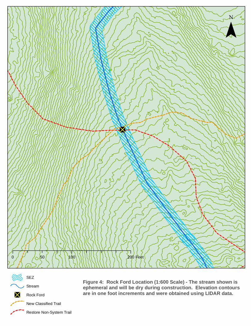
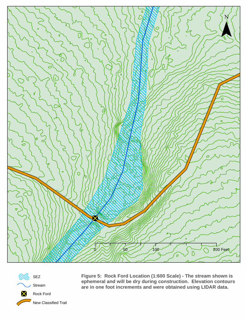
When a trail alignment crosses an intermittent or ephemeral channel, the channel will be
stabilized and maintained to convey water across the trail. In most instances, large rocks

10
embedded into the banks will stabilize the crossing sufficiently. In instances where channel is
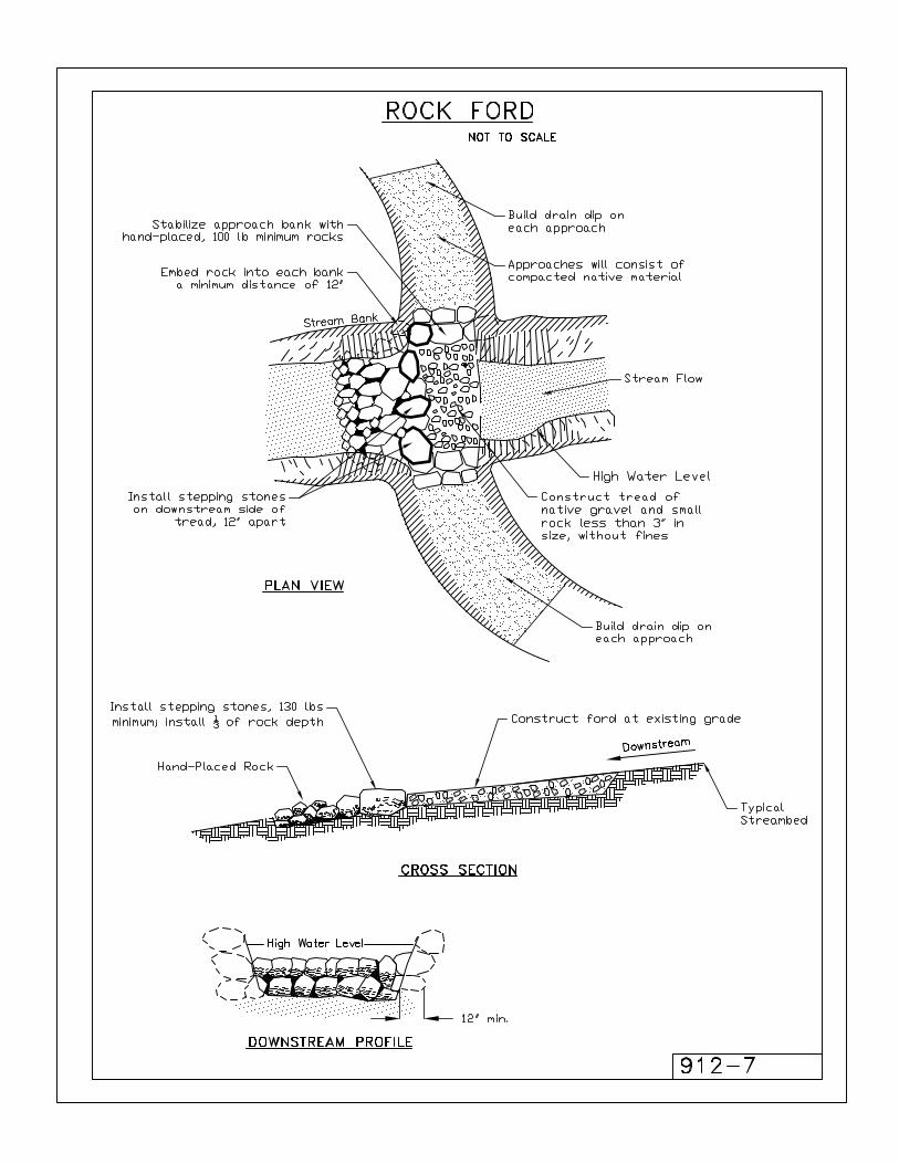
more defined, or the flows are obviously higher, a rock ford will be constructed (see Appendix
C, Angora Trail drawings). Rock ford construction has been identified near Tahoe Mountain
Road and off of Pyramid Circle (see Figures 2, 4, and 5 for specific locations). These specific
locations have well defined channels and have the potential for higher flows and more erosion,
and ford construction will give them more stabilization. Native material will be used for all ford
construction. Fords will be constructed when the channel is dry, and will be built with hand
tools or a mini excavator. If the fords are constructed with a mini excavator, they will access the
construction site from Forest Service Roads and up the constructed approach trail. Trails will
also be obliterated in wet areas. If the trail has started to restore itself (i.e. vegetation has
started to grow and the trail is stabilized) minimal disturbance will be made. Other trails will be
recontoured, stabilized, and camouflaged with natural materials.
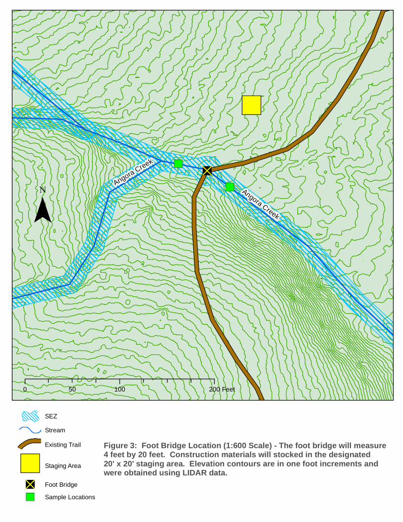
A trail bridge will be constructed across Angora Creek (see Figure 2 and Figure 3 for the specific
location). Currently, there are large logs and debris within the streambed that have created
ponding and modified the original alignment. This organic debris will be removed, and two
large rock abutments will be placed with minimal disturbance to the creek. Approach and
abutment construction will be the only disturbance within the creek, and is only expected to
take 2 days. The bridge superstructure (deck, rail, and finish work) construction will not have
any effect on the creek. There will be no concrete used in the construction of the bridge. All
treated wood materials will follow the treatment requirements found in “Best Management
Practices for the Use of Treated Wood in Aquatic Environments,” published by the Western
Wood Preservers Association. Native material or imported, clean material will be used for the
approaches and stream banks. Stone will be used to build up the banks and allow for 24 inches
of clearance from the creek bed. Native material and stone will be used to backfill and armor
the abutments. The design has considered the floodplain, and the structure will not impact
aquatic species. Construction will take place during low or no flow. The clear water diversion
BMP has been identified (Appendix B, CASQA specifications) and will be utilized if there is flow
during construction. See Section III.D. Dewatering and Diversion Plan Narrative for more
diversion information.
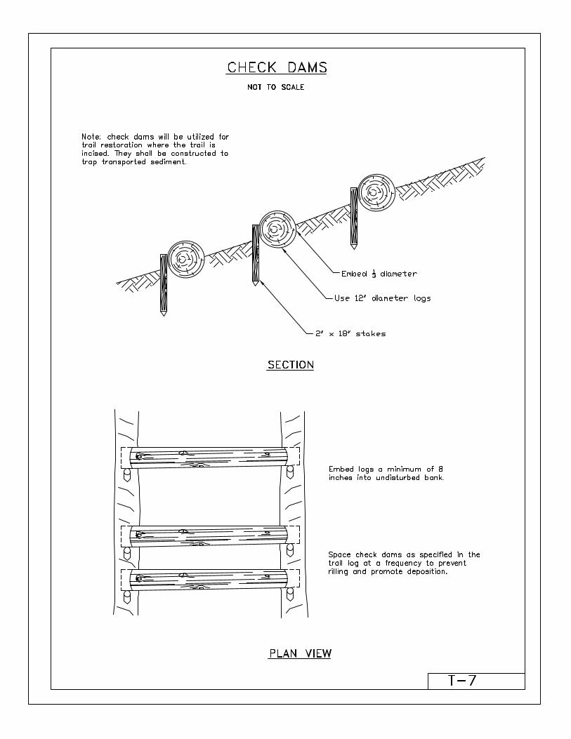
In addition, gullies and headcuts in the Gardner Mountain Meadow associated with legacy user
created trails will be stabilized to restore natural water retention and drainage patterns. This
will primarily be accomplished through the decommissioning of user-created trails and properly
installed drainage on newly constructed trail. However, headcuts will be stabilized with loose
rock check dams, and gullies will be stabilized using a combination of loose rock check dams
and biotechnical structures (willow stakes). These structures will be installed by hand, except
for structures directly adjacent to areas where equipment is being utilized to construct or
decommission trails. Locations on gullies and headcuts are shown on Figure 2A.1.
Mewu
k Dr
Pyram
id Cir
Mule Deer
Cir
Taho
e Mtn
Rd
Seneca Dr
Shoshone St
Panther Ln
Nez Perc
e Dr
89
50
Forest Mtn Rd
0 0.25 0.5 0.75 10.125Miles
StreamSEZ/100 Yr. FloodplainAngora Fire PerimeterHighwaysLocalRoad
¯
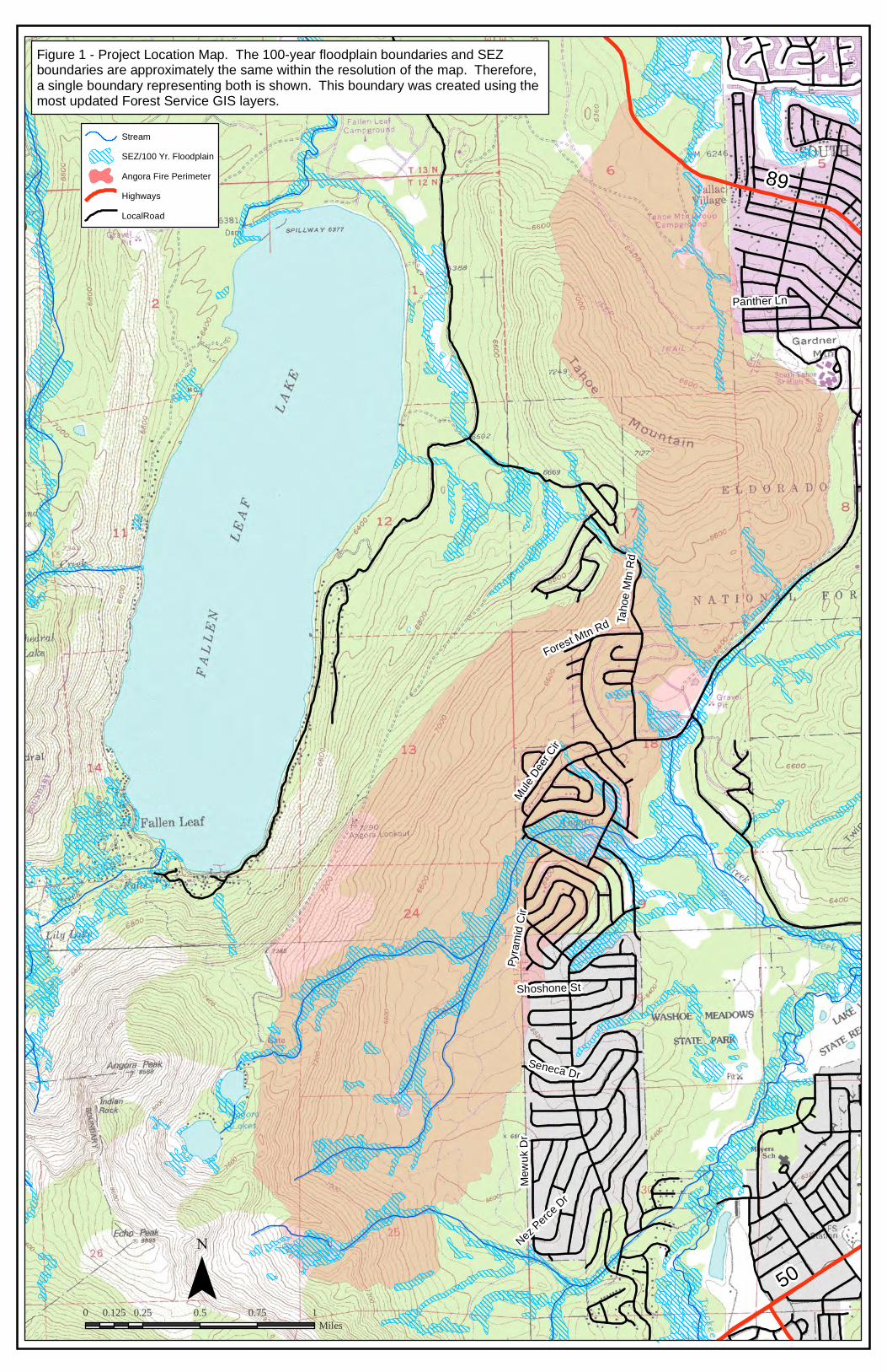
Figure 1 - Project Location Map. The 100-year floodplain boundaries and SEZ boundaries are approximately the same within the resolution of the map. Therefore, a single boundary representing both is shown. This boundary was created using the most updated Forest Service GIS layers.

12

13
II.A.2. Site Location
The Angora burn area is over 2700 acres, and has no single address. Generally, the project can be
accessed from Lake Tahoe Boulevard, southwest of the intersection of Highway 89 and Highway 50 in
South Lake Tahoe, CA. See Figure 1, the Site Location Map, to determine key areas within the project.
II.B. WDID
Once the WDID number is issued to the Forest Service for this project, it will be added as a
SWPPP Amendment as specified in section I.H, Required Changes.
II.C. Construction Schedule
The estimated schedule for planned work is below. This schedule will be updated as needed
throughout the project and used internally by LTBMU staff to plan project resources.
Trail decommissioning and restoration will be conducted as new trails are completed. This will reduce multiple trails being used and additional erosion occurring. Trail construction in SEZs will be scheduled when areas are as dry as possible, and construction/restoration will be completed as swiftly as possible to reduce the risk of additional erosion.
Table 3. Construction Schedule
Zone 1 (North) Tahoe Mountain Road to northern boundary adjacent to Camp Richardson
Zone 2 (Central) Tahoe Mountain Road to Pyramid drive along Angora Creek
Zone 3 (South) Angora Creek to the southern project boundary adjacent Mewuk drive
May 12, 2013 – June 15, 2013
Zone 1
Trail work will begin on Tahoe Mountain. This area is a south facing slope with limited vegetation and is snow free. This will allow lower elevation trails in wet soils to continue to dry out. Trail construction will then move to trails along Hwy 89 and Lake Tahoe Blvd.
June 16, 2013 – July 13, 2013
Zone 3
Project work will be focused at the south end of Mewuk Drive and move north towards Angora Creek. This will allow wet areas near Seneca Pond to be as dry as possible before work takes place in that area.
July 14, 2013 – August 23, 2013
Zone 2
Project work will be focused at the north end Forest Mountain Road and move south towards Angora Creek. This will allow flows in Angora Creek to be as low as possible before work takes place in that area.
14
II.D. Potential Construction Site Pollutants of Concern and Sources
The following is a list of construction materials that will be used and that have the potential to
contribute pollutants, other than sediment, to storm water runoff:
Vehicle fluids, including oil, grease, petroleum and coolants;
BMP materials (sandbags, geotextile fabrics); and
General litter.
The following is a list of construction activities that have the potential to contribute sediment to
storm water discharges:
Clearing and grubbing operations;
Bank stabilization; and
Soil and rock import operations.
II.E. Site Location Map(s)
See Figure 1 for the Site Location Map.
Section IX.H.2 of Construction General Permit requires the following map information
Construction Limit Boundaries – the boundary for this project is the Angora burn
area perimeter (see Figures 1 and 2).
Equipment and material stockpile areas – staging areas are shown on Figure 2, and
will only be located on already disturbed areas (such as timber landings or Forest
Service roads). The only materials that will be stored in staging areas will be
construction material (rock, aggregate base, and fiber rolls) and equipment (mini
excavator or trail dozer). In order to get fuel to this small equipment along the trail,
small fuel containers will be transported (on foot or with an ATV) along Forest
Service system roads and trails. Access for trail construction and restoration will be
limited to these system roads and trails. All equipment will be cleaned before it
reaches the project site. All equipment servicing will occur off the project site.
Existing vegetation to be preserved – Riparian vegetation boundaries can be seen on
Figures 3, 4, and 5. Excessive disturbance of existing vegetation will be controlled
through quality assurance. A superintendent will be on site at all times, and trail
alignments will be flagged prior to construction.
Surface water locations – see Figures 2, 3, 4 and 5. Figure 2, the Disturbed Soil Area
Map, specifically maps all defined waterways and riparian vegetation using the latest
Forest Service GIS data.
15
BMP locations – BMPs are not shown on attached maps because of the nature of
trail construction. Loose soils will be stabilized daily. Permanent BMPs will be built
into the trail tread, and there will be very little disturbance outside of the trail prism.
Temporary BMPs will be specifically used for the construction of the trail bridge
across Angora Creek. If there is enough water in Angora Creek, and dewatering is
required for abutment construction, CASQA specifications NS-2, Dewatering
Operations and NS-5, Clear Water Diversion will be used as construction
specifications. Sandbags with 6mil plastic will be utilized, as well as with straw
wattles between the creek and any stockpiled materials (although any stockpiled
materials will be in place for a maximum of 1 week). If material is stockpiled in
staging areas, they will be stabilized with straw wattles and/or plastic covers.
Disturbed Soil Areas – see Figure 2, Disturbed Soil Area maps. Disturbance will be
limited to the trail alignments shown on the maps. These maps will be kept updated
to reflect site conditions.
Post-construction storm water structures and controls – see Appendix C, Angora Trail
Drawings.
Locations of designated storm water discharge sampling – see Figure 3. See also V.C
Water Quality Sampling and Analysis, for specific sampling requirements.

16
17
III. Best Management Practices
III.A. Site Management Narrative
Construction site management shall consist of controlling potential sources of water pollution
before they come in contact with storm water systems or watercourses. Appropriate site
management measures shall be implemented to control material pollution and manage waste
by implementing effective handling, storage, use and disposal practices. Additionally, many
non-storm water pollution control BMPs (below) are necessary for proper site management.
Waste management and materials pollution control BMPs shall be implemented to minimize
storm water contact with construction materials, wastes and service areas and to prevent
materials and wastes from being discharged off-site. The primary mechanisms for storm water
contact that shall be addressed include:
Direct contact with precipitation
Contact with storm water run-on and runoff
Wind dispersion of loose materials
Direct discharge to the streams and watercourse through spills or dumping
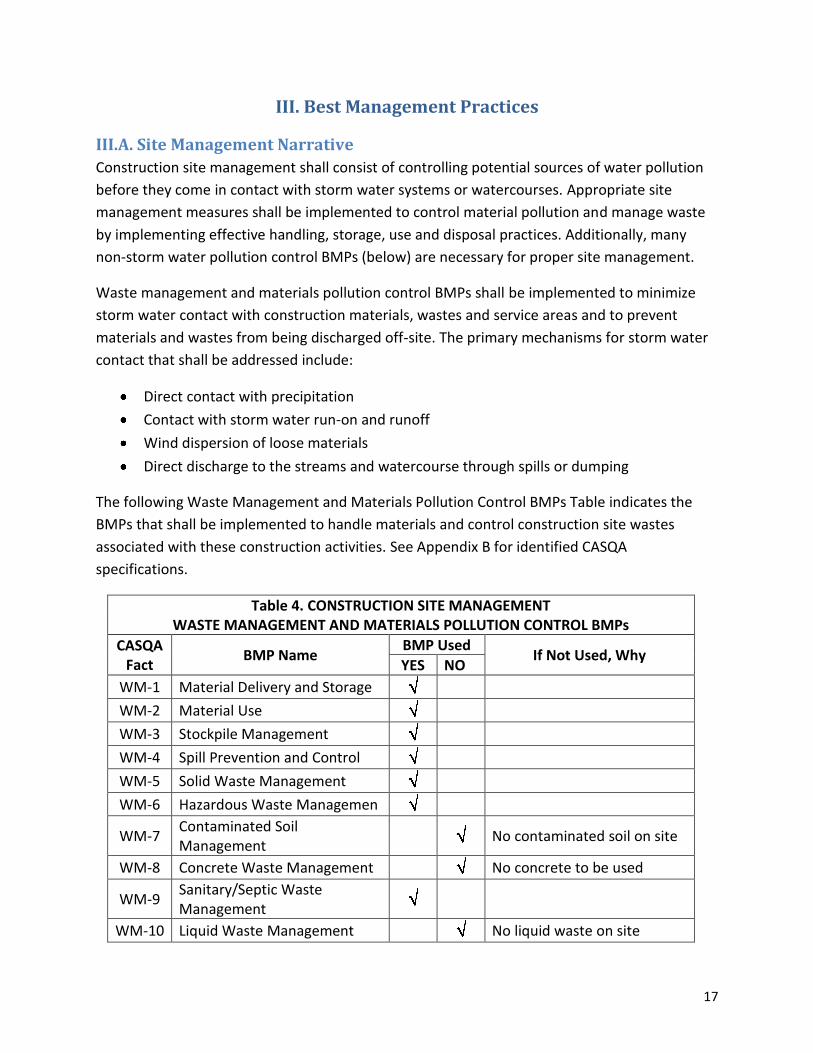
The following Waste Management and Materials Pollution Control BMPs Table indicates the
BMPs that shall be implemented to handle materials and control construction site wastes
associated with these construction activities. See Appendix B for identified CASQA
specifications.
Table 4. CONSTRUCTION SITE MANAGEMENT WASTE MANAGEMENT AND MATERIALS POLLUTION CONTROL BMPs
CASQA Fact
BMP Name BMP Used
If Not Used, Why YES NO
WM-1 Material Delivery and Storage
WM-2 Material Use
WM-3 Stockpile Management
WM-4 Spill Prevention and Control
WM-5 Solid Waste Management
WM-6 Hazardous Waste Managemen
WM-7 Contaminated Soil Management
No contaminated soil on site
WM-8 Concrete Waste Management No concrete to be used
WM-9 Sanitary/Septic Waste Management
WM-10 Liquid Waste Management No liquid waste on site
18
The following list of BMPs and narrative explain how the selected BMPs will be incorporated
into the project. Where CASQA fact sheets contradict information contained in the Technical
Specifications or the Drawings, the more stringent criteria (as determined by QSD) shall apply.
Selection criteria will be documented in a SWPPP Amendment.
WM-1, WM-2 Materials Delivery, Storage and Use
In general, BMPs shall be implemented to help prevent discharges of construction materials
during delivery, storage and use. The general material storage area shall be located in the
staging areas as shown on Figure 2. The stockpiles are located to avoid run-on. A barrier shall
be provided along the downslope edge of the staging areas to prevent runoff leaving the area.
If QSP determines there is a risk of run-on, a barrier shall be provided along the upslope edge of
the staging area.
WM-3 Stockpile Management
Stockpile Management shall be implemented to reduce or eliminate pollution of storm water
from stockpiles of soil and rock materials. Any utilized stockpiles will be located in already
disturbed and flat areas, typically old timber landings or a Forest Service system road.
Stockpiles shall be surrounded with sediment controls. If a stockpile is inactive for 14 days it will
be covered. No stockpiles will remain at the end of the construction season.
WM-4 Spill Prevention and Control
Spill Prevention and Control shall be implemented to contain and clean-up spills and prevent
material discharges to the streams and waterways.
WM-5, WM-6 Solid and Hazardous Waste Management
Solid Waste Management and Hazardous Waste Management BMPs shall be implemented to
minimize storm water contact with waste materials and prevent waste discharges. The only
solid wastes in this project will be organics from grubbing and construction waste. All waste
shall be disposed of offsite daily.
The only liquid hazardous waste in this project will be equipment fuel. Fuel will not be stored on
site; it will be transported in small containers to equipment along the trail as needed.
WM-9 Sanitary and Septic Wastes
Portable toilets shall be located and maintained at the staging areas for the duration of the
project. Specific locations will be determined in the field by the QSD. Weekly maintenance shall
be provided and wastes shall be disposed offsite. The toilets shall be located away from
concentrated flow paths. Toilet location shall not interfere with traffic flow.
19
III.B. Sediment and Erosion/Stabilization Control Narrative
III.B.1. Erosion Control
Erosion control is any source control practice that protects the soil surface and prevents soil
particles from being detached by rainfall, flowing water or wind. Erosion control consists of
using project scheduling and planning to reduce soil and/or vegetation disturbance, controlling
drainage in disturbed areas and preparing and stabilizing disturbed soil areas.
This construction project will implement the following practices to provide effective temporary
and final erosion control during construction:
Preserve existing vegetation where required and when feasible;
The area of soil disturbing operations shall be controlled such that either erosion control
BMPs (Table 5) can be quickly and effectively implemented or the site can be
permanently stabilized in that area;
Non-active areas will be stabilized within 14 days of cessation of construction activities;
Prior to the completion of construction, apply permanent stabilization to disturbed soil
areas. This shall include outsloped, compacted trail surfaces with installed drainage
features.
Sufficient erosion control materials shall be maintained onsite to allow implementation in
conformance with this SWPPP. This includes implementation requirements for active and non-
active areas that require deployment of BMPs before the onset of rain.
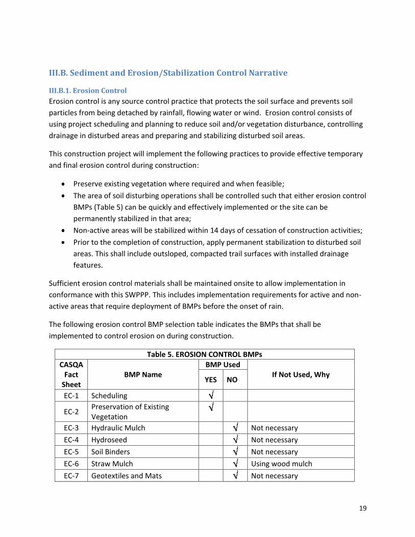
The following erosion control BMP selection table indicates the BMPs that shall be
implemented to control erosion on during construction.
Table 5. EROSION CONTROL BMPs
CASQA Fact
Sheet BMP Name
BMP Used If Not Used, Why
YES NO
EC-1 Scheduling
EC-2 Preservation of Existing Vegetation
EC-3 Hydraulic Mulch Not necessary
EC-4 Hydroseed Not necessary
EC-5 Soil Binders Not necessary
EC-6 Straw Mulch Using wood mulch
EC-7 Geotextiles and Mats Not necessary

20
EC-8 Wood Mulching
EC-9 Earth Dikes and Drainage Swales
EC-10 Velocity Dissipation Devices Not necessary
EC-11 Slope Drains Not necessary
EC-12 Stream Bank Stabilization
EC-14 Compost Blankets Not necessary
EC-15 Soil Preparation- Roughening
EC-16 Non-Vegetated Stabilization
WE-1 Wind Erosion Control
The following list of BMPs and narrative explain how the selected BMPs will be incorporated
into the project. Where CASQA fact sheets contradict information contained in the Technical
Specifications or the Drawings, the more stringent criteria (as determined by the QSD) shall
apply. Selection criteria will be documented in a SWPPP Amendment.
EC-1, EC-2 Scheduling and Preservation of Existing Vegetation
Scheduling is the most important BMP for this project. Generally, no more soil will be disturbed
than what can be permanently stabilized at the end of each day. Surface disturbance activities
will begin after May 1 and continue no later than October 15, depending on stream flow,
ground water levels and weather conditions. Grading activities are scheduled to be completed
by October 5 with winterization taking place from October 5 to October 15. A grading ordinance
exemption may be requested from TRPA and LRWQCB if the QSD and Project Engineer deem it
necessary and appropriate to work past October 15. When there is a 30 percent or greater
chance of precipitation in the project area as predicted by the National Oceanographic and
Atmospheric Administration (NOAA), further actions will be taken (see section IV.B. Rain Event
Action Plan Narrative).
For the stream crossings on trails, work will be scheduled during periods of predicted clear
weather. Additional work will only be started on crossings within the first two days of the work
week (Monday or Tuesday) to allow for completion and/or stabilization of the crossings before
weekends.
EC-8 Wood Mulching
Wood mulch will be used in combination with slash material as a long-term stabilization for
disturbed areas of the project.
21
Wood mulch may be used to cover small exposed soil areas that have the potential to release
sediment discharge to a live waterbody prior to a forecast storm event. If wood mulch is used in
such an instance, it shall be applied to a depth that will protect soil and prevent movement of
mulch (approximately 2”-4”).
Additionally, wood mulch will be used in combination with wood slash material to stabilize and
provide cover for disturbance areas along trail alignments and stockpile areas, once these areas
are no longer needed. Wood mulch will be applied on disturbed areas outside of trail
alignments prior to predicted precipitation, upon completion of an area, and as needed as
determined by the QSP.
EC-9 Drainage Swales
Drainage features will be used as a permanent BMP and will be constructed on trails to convey
water from the travel surface. See construction drawings in Appendix C for construction details
and frequencies.
EC-12 Stream Bank Stabilization
Stream crossings on Angora Trails will be constructed to promote stream bank stability. See
construction drawings in Appendix C for details.
EC-15 Soil Preparation / Roughening
Compacted areas to be decommissioned will be roughened to increase water infiltration
capacity and prepare the surface for revegetation. This will be accomplished by ripping the soil
to a depth of 6 to 12 inches with the teeth on an excavator bucket, a proper hand tool, or
equivalent method.
Non-Vegetated Stabilization
Loose rock structures will be installed in the Gardner Mountain Meadow to stabilized headcuts
and gullies. Rocks structures will be sized according to the size of the gully/head cut.
WE-1 Wind Erosion Control
Water may be applied to heavily disturbed staging areas to control dust, and the water will be
applied using water trucks. Water application rates will be minimized as necessary to prevent
runoff and ponding. Water equipment leaks will be repaired as soon as possible.During windy
conditions (forecast or actual wind conditions of approximately 25 mph or greater), dust
control will be applied to all non-stabilized areas to adequately control wind erosion.
22
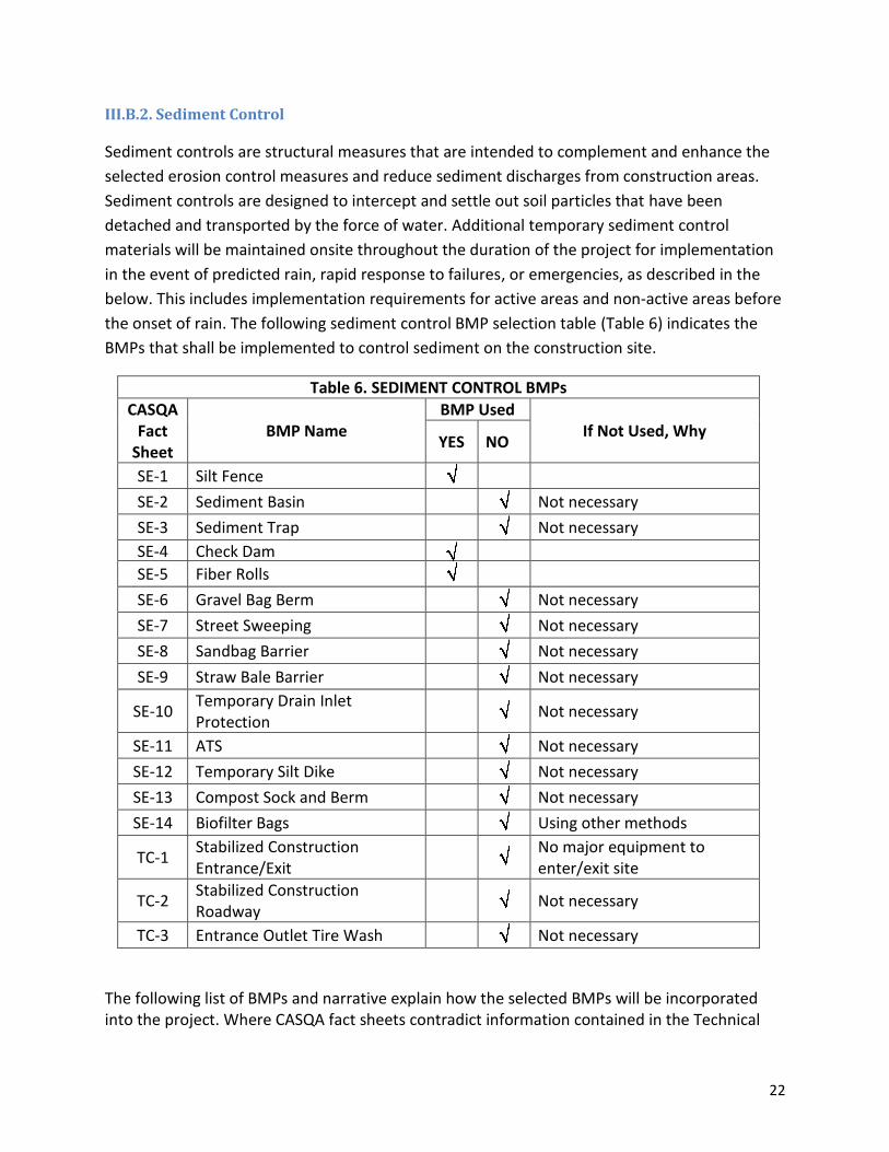
III.B.2. Sediment Control
Sediment controls are structural measures that are intended to complement and enhance the
selected erosion control measures and reduce sediment discharges from construction areas.
Sediment controls are designed to intercept and settle out soil particles that have been
detached and transported by the force of water. Additional temporary sediment control
materials will be maintained onsite throughout the duration of the project for implementation
in the event of predicted rain, rapid response to failures, or emergencies, as described in the
below. This includes implementation requirements for active areas and non‐active areas before
the onset of rain. The following sediment control BMP selection table (Table 6) indicates the
BMPs that shall be implemented to control sediment on the construction site.
Table 6. SEDIMENT CONTROL BMPs
CASQA Fact
Sheet BMP Name
BMP Used If Not Used, Why
YES NO
SE-1 Silt Fence
SE-2 Sediment Basin Not necessary
SE-3 Sediment Trap Not necessary
SE-4 Check Dam
SE-5 Fiber Rolls
SE-6 Gravel Bag Berm Not necessary
SE-7 Street Sweeping Not necessary
SE-8 Sandbag Barrier Not necessary
SE-9 Straw Bale Barrier Not necessary
SE-10 Temporary Drain Inlet Protection
Not necessary
SE-11 ATS Not necessary
SE-12 Temporary Silt Dike Not necessary
SE-13 Compost Sock and Berm Not necessary
SE-14 Biofilter Bags Using other methods
TC-1 Stabilized Construction Entrance/Exit
No major equipment to enter/exit site
TC-2 Stabilized Construction Roadway
Not necessary
TC-3 Entrance Outlet Tire Wash Not necessary
The following list of BMPs and narrative explain how the selected BMPs will be incorporated into the project. Where CASQA fact sheets contradict information contained in the Technical
23
Specifications or the Drawings, the more stringent criteria (as determined by the QSD) shall apply. Selection criteria will be documented in a SWPPP Amendment. SE-1 Silt Fence Silt fence will be used as needed for the stream crossing construction. Sandbags and 6mil plastic will be the primary method for water diversion. Additional installations may be required at the direction of the QSD or QSP. SE-4 Check Dam Loose rock check dams will be installed in the Gardner Mountain Meadow to stabilized head cuts and gullies. Rocks will be sized according to the size of the gully/head cut. SE-5 Fiber Rolls Fiber rolls will be used to surround any stockpile area that is inactive for more than 14 days, or when there is predicted precipitation. Additional fiber rolls will be kept on-site to be deployed as needed.
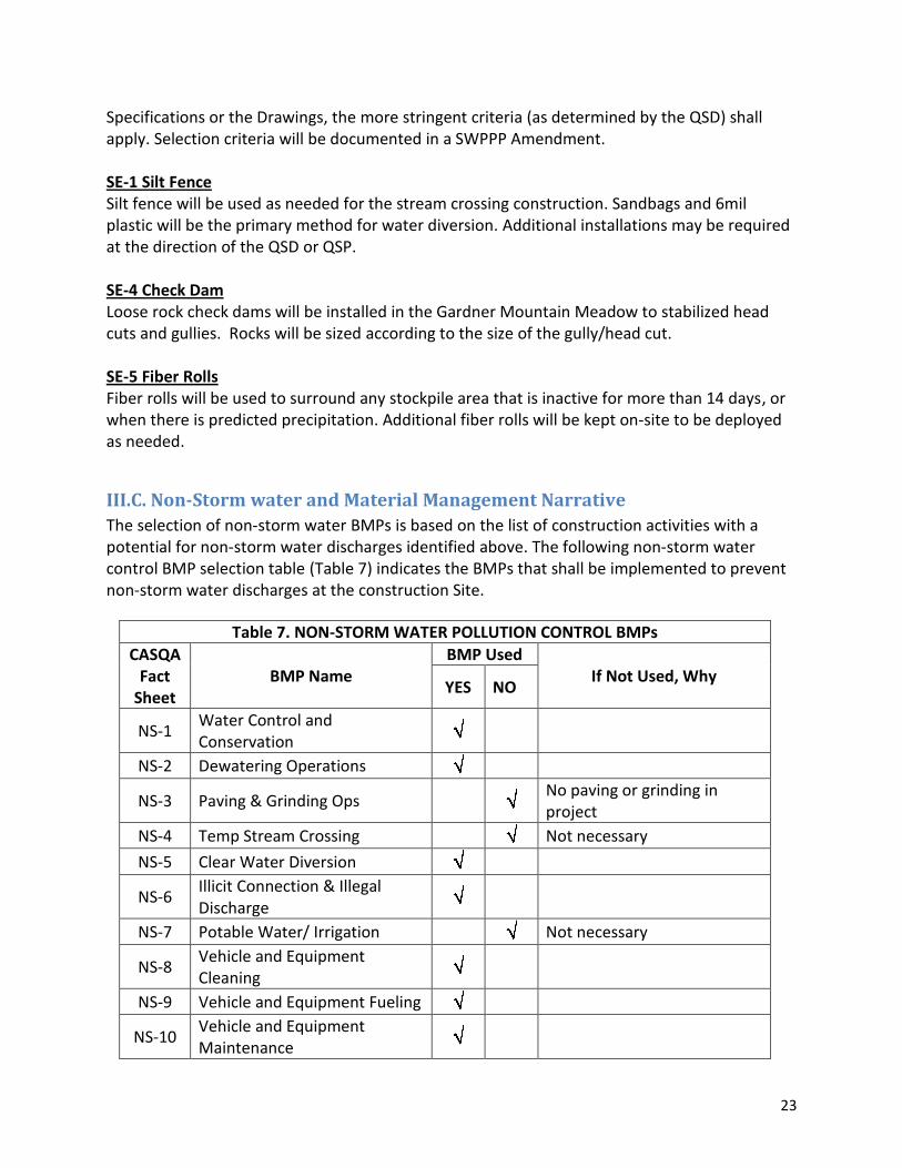
III.C. Non-Storm water and Material Management Narrative
The selection of non‐storm water BMPs is based on the list of construction activities with a potential for non‐storm water discharges identified above. The following non‐storm water control BMP selection table (Table 7) indicates the BMPs that shall be implemented to prevent non‐storm water discharges at the construction Site.
Table 7. NON-STORM WATER POLLUTION CONTROL BMPs
CASQA Fact
Sheet BMP Name
BMP Used If Not Used, Why
YES NO
NS-1 Water Control and Conservation
NS-2 Dewatering Operations
NS-3 Paving & Grinding Ops No paving or grinding in project
NS-4 Temp Stream Crossing Not necessary
NS-5 Clear Water Diversion
NS-6 Illicit Connection & Illegal Discharge
NS-7 Potable Water/ Irrigation Not necessary
NS-8 Vehicle and Equipment Cleaning
NS-9 Vehicle and Equipment Fueling
NS-10 Vehicle and Equipment Maintenance
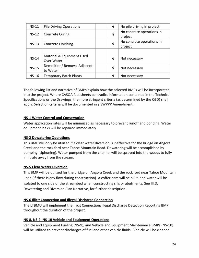
24
NS-11 Pile Driving Operations No pile driving in project
NS-12 Concrete Curing No concrete operations in project
NS-13 Concrete Finishing No concrete operations in project
NS-14
Material & Equipment Used Over Water
Not necessary
NS-15 Demolition/ Removal Adjacent to Water
Not necessary
NS-16 Temporary Batch Plants Not necessary
The following list and narrative of BMPs explain how the selected BMPs will be incorporated into the project. Where CASQA fact sheets contradict information contained in the Technical Specifications or the Drawings, the more stringent criteria (as determined by the QSD) shall apply. Selection criteria will be documented in a SWPPP Amendment.
NS-1 Water Control and Conservation
Water application rates will be minimized as necessary to prevent runoff and ponding. Water equipment leaks will be repaired immediately. NS-2 Dewatering Operations
This BMP will only be utilized if a clear water diversion is ineffective for the bridge on Angora Creek and the rock ford near Tahoe Mountain Road. Dewatering will be accomplished by pumping (siphoning). Water pumped from the channel will be sprayed into the woods to fully infiltrate away from the stream. NS-5 Clear Water Diversion
This BMP will be utilized for the bridge on Angora Creek and the rock ford near Tahoe Mountain
Road (if there is any flow during construction). A coffer dam will be built, and water will be
isolated to one side of the streambed when constructing sills or abutments. See III.D.
Dewatering and Diversion Plan Narrative, for further description.
NS-6 Illicit Connection and Illegal Discharge Connection
The LTBMU will implement the Illicit Connection/Illegal Discharge Detection Reporting BMP throughout the duration of the project. NS-8, NS-9, NS-10 Vehicle and Equipment Operations
Vehicle and Equipment Fueling (NS-9), and Vehicle and Equipment Maintenance BMPs (NS-10) will be utilized to prevent discharges of fuel and other vehicle fluids. Vehicle will be cleaned

25
and inspected (NS-8) prior to arrival on site. Vehicle cleaning will not be performed onsite, except as part of normal maintenance to remove excess dirt/mud from equipment. This type of cleaning will take place within the staging area (BMP area) and be performed such that excess runoff is not generated.
Fuel trucks, each equipped with absorbent spill clean‐up materials, shall be used for all onsite fueling. All fueling will take place within the staging area. Drip pans or absorbent pads shall be used during all vehicle and equipment maintenance activities that involve grease, oil, solvents, or other vehicle fluids. All vehicle maintenance shall be conducted at least 50 feet away from stream channels and on a level graded area. If mobile maintenance is necessary due to an equipment failure within the construction area that prevents the equipment from be moved to the staging area, drip pans and/or absorbent pads shall be used to prevent any contamination of the site.
III.D. Dewatering and Diversion Plan Narrative
See Figure 3 for specific diversion locations. The footbridge over Angora Creek (see Figure 3) will have a coffer dam in place during construction (if there is any flow at that time). A sandbag coffer dam, sealed with 6 millimeter plastic, will channel the flow to one side of the streambed while the rock abutment is placed. Any uncollected water will be pumped away from the creek, and all water will infiltrate in the adjacent upland area. NS-5, Clean Water Diversion from the CASQA fact sheets (Appendix B), will be the main guide during the abutment placement. Prior to the re-introduction of stream flow, the channel will be “seasoned” by slowly filling the diversion area and then pumping to remove fine sediment, until turbidity reaches background levels or no greater than a 10% increase above background levels. The coffer dams will then be completely removed.
III.E. Active Treatment System Plan Narrative
No active treatment system operations are planned as part of this project.
III.F. Post-Construction Storm Water Management Measures Narrative
All trails are designed to function during storms. All trail alignments will be compacted, and
drainage dips will be spaced and built to effectively minimize erosion. The footbridge spanning
Angora Creek will be designed to clear most storm water and allow for overtopping during
major storms. The rock ford near Tahoe Mountain Road will be sufficiently armored to handle
large storms. This project will be monitored post-construction to determine if the trails are
functioning as designed. The sites will be visited and a visual survey of the project area will be
completed in the following spring as soon as accessible (post-snowmelt). Additionally, the
Angora Trails Restoration project will be part of the Forest level effectiveness monitoring
(BMPEP).
III.G. Schedule for BMP Implementation
BMPs will be implemented, modified, and maintained appropriately for the site and weather
conditions encountered during the project. If a staging area is utilized, it will be used for a

26
maximum of 1 week, and will be placed in its pre-existing condition before moving to another
area. Fiber rolls will be placed at the base of all material stockpiles, and if precipitation is
expected, the pile will be covered.
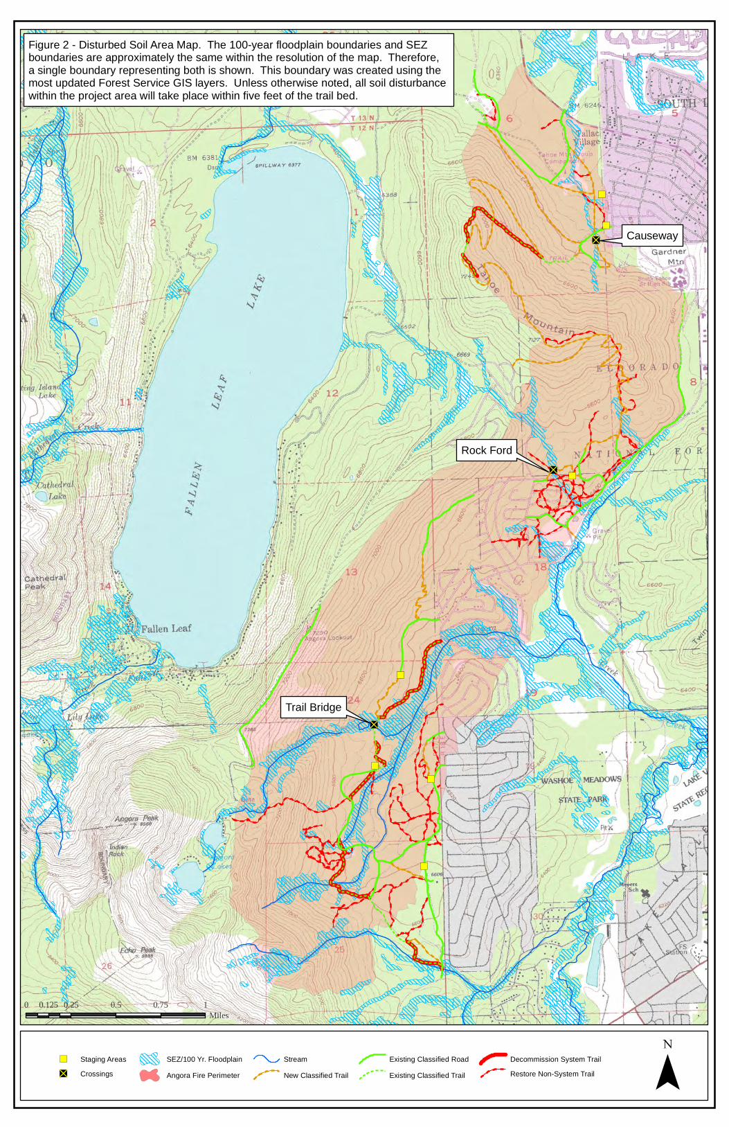
III.H. BMP and Disturbed Soil Area mapsFigure 2 shows the disturbed soil areas (DSAs), stream crossings, and staging area BMPs for this project.
Due to the large area of construction, orange construction fence will only be installed to define the
staging areas. Section IX. H. Mapping Requirements, of the R6T-2011-0019 requires that DSA maps be of
a scale no smaller than 1 inch equals 50 feet (1:600). Figure 2 does not meet this requirement. Because
of the large area of this project, only key areas are shown on maps to this scale (Figures 3, 4, and 5).
")
")
")
")
")
")
")
"D
"D
"D
0 0.25 0.5 0.75 10.125Miles
") Staging Areas"D Crossings
SEZ/100 Yr. FloodplainAngora Fire Perimeter
StreamNew Classified Trail
Existing Classified RoadExisting Classified Trail
Decommission System TrailRestore Non-System Trail ¯
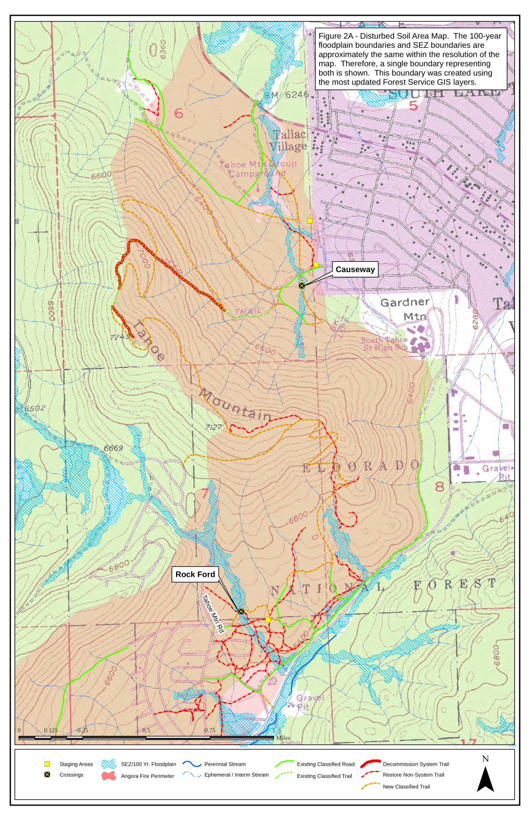
Figure 2 - Disturbed Soil Area Map. The 100-year floodplain boundaries and SEZ boundaries are approximately the same within the resolution of the map. Therefore, a single boundary representing both is shown. This boundary was created using the most updated Forest Service GIS layers. Unless otherwise noted, all soil disturbance within the project area will take place within five feet of the trail bed.
Causeway
Rock Ford
Trail Bridge

28
")
")
")
")
")
")
"D
"D
"D
")
"D "D
Tahoe Mtn Rd
0 0.25 0.5 0.75 10.125Miles
") Staging Areas"D Crossings
SEZ/100 Yr. FloodplainAngora Fire Perimeter
Perennial StreamEphemeral / Interm Stream
Existing Classified RoadExisting Classified Trail
Decommission System TrailRestore Non-System TrailNew Classified Trail ¯
Figure 2A - Disturbed Soil Area Map. The 100-year floodplain boundaries and SEZ boundaries are approximately the same within the resolution of the map. Therefore, a single boundary representing both is shown. This boundary was created using the most updated Forest Service GIS layers.
Causeway
Rock Ford

30
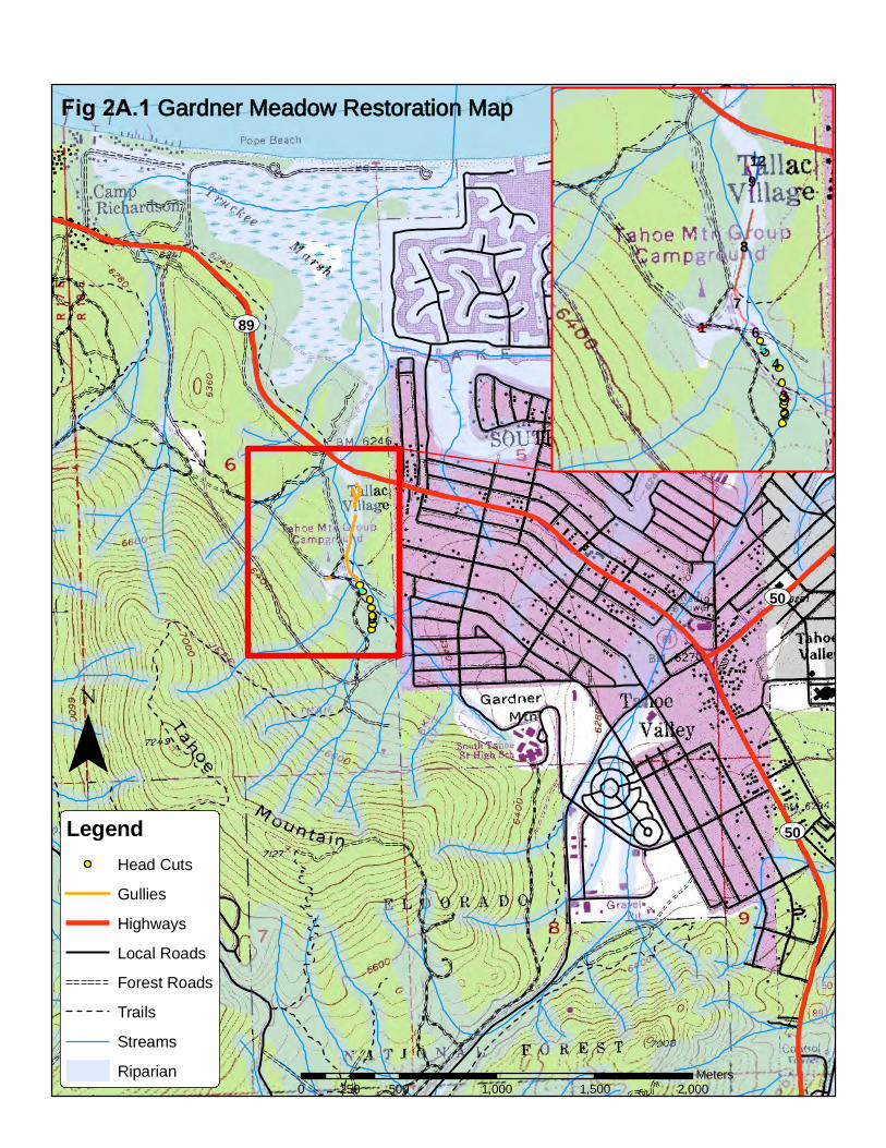
Fig 2A.1 Gardner Meadow Restoration Map
¯Legend
Head CutsGulliesHighwaysLocal RoadsForest RoadsTrailsStreamsRiparian
0 500 1,000 1,500 2,000250Meters
8
7
9
6
3
12
1
45
2
UV50
UV50
UV89

")
")
")
")
")
")
"D
"D
"D
")
"D "D
Tahoe Mtn Rd
Pyram
id Cir
0 0.25 0.5 0.75 10.125Miles
") Staging Areas"D Crossings
SEZ/100 Yr. FloodplainAngora Fire Perimeter
Perennial StreamEphemeral / Interm Stream
Existing Classified RoadExisting Classified Trail
Decommission System TrailRestore Non-System TrailNew Classified Trail ¯
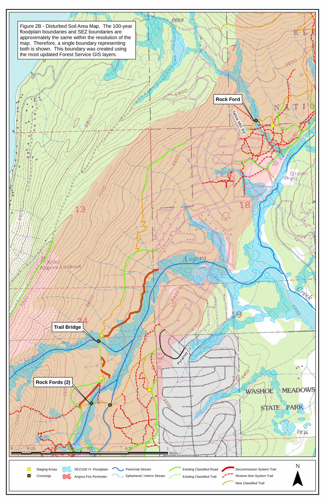
Figure 2B - Disturbed Soil Area Map. The 100-year floodplain boundaries and SEZ boundaries are approximately the same within the resolution of the map. Therefore, a single boundary representing both is shown. This boundary was created using the most updated Forest Service GIS layers.
Rock Ford
Trail Bridge
Rock Fords (2)

32
")
")
")
")
")
")
"D
"D
"D
")
"D "D
Mewu
k Dr
Pyram
id Cir
0 0.25 0.5 0.75 10.125Miles
") Staging Areas"D Crossings
SEZ/100 Yr. FloodplainAngora Fire Perimeter
Perennial StreamEphemeral / Interm Stream
Existing Classified RoadExisting Classified Trail
Decommission System TrailRestore Non-System TrailNew Classified Trail ¯
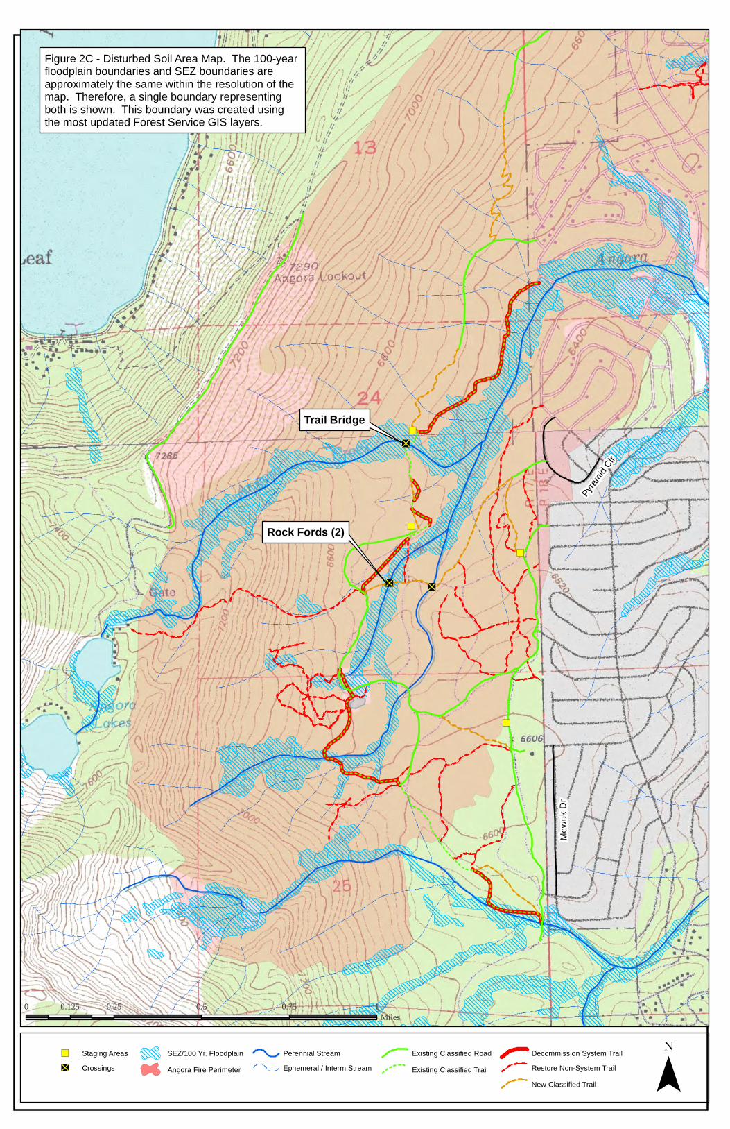
Figure 2C - Disturbed Soil Area Map. The 100-year floodplain boundaries and SEZ boundaries are approximately the same within the resolution of the map. Therefore, a single boundary representing both is shown. This boundary was created using the most updated Forest Service GIS layers.
Trail Bridge
Rock Fords (2)

34
")
")
")
"D")
")
")
Angora Creek
Angora Creek
SEZStreamExisting Trail
") Staging Area
"D Foot Bridge") Sample Locations
¯
0 100 20050 Feet
Figure 3: Foot Bridge Location (1:600 Scale) - The foot bridge will measure 4 feet by 20 feet. Construction materials will stocked in the designated 20' x 20' staging area. Elevation contours are in one foot increments and were obtained using LIDAR data.

36
"D
SEZStream
"D Rock FordNew Classified TrailRestore Non-System Trail
¯
0 100 20050 Feet
Figure 4: Rock Ford Location (1:600 Scale) - The stream shown isephemeral and will be dry during construction. Elevation contoursare in one foot increments and were obtained using LIDAR data.

38
"D
SEZStream
"D Rock FordNew Classified Trail
¯
0 100 20050 Feet
Figure 5: Rock Ford Location (1:600 Scale) - The stream shown isephemeral and will be dry during construction. Elevation contoursare in one foot increments and were obtained using LIDAR data.

40
41
IV. BMP Inspection, maintenance and Rain Event Action Plans
IV.A. BMP Inspection and Maintenance Narrative
The General Permit requires that an inspection of the construction site be made at the end of
each work day and before, during and after qualifying rain events. Additionally, during the
winter or inactive periods, inspections must be conducted at least once per month during
daylight hours. Because all projects are located at high elevation, it is expected that the entire
area will be covered in snow from approximately December through April. Therefore, monthly
inspections will not occur during these months. Monthly inspections will continue through the
spring following final construction to ensure permanent soil stabilization measures function
through spring runoff.
The purpose of the inspections is to discover potential water quality problems so that
corrective measures can be implemented immediately. A BMP inspection checklist will be filled
out for each inspection and maintained on-site with the SWPPP. A blank inspection checklist
can be found an Appendix D. Completed checklists shall be kept with the SWPPP. Inspections of
BMPs are conducted to identify and record:
BMPs that are properly installed;
BMPs that need maintenance to operate effectively;
BMPs that have failed; or
BMPs that could fail to operate as intended.
IV.B. Rain Event Action Plan Narrative
The Rain Event Action Plan (REAP) is a document designed to be used as a planning tool by the
QSP to protect exposed portions of the project sites during precipitation events and to ensure
that the discharger has adequate materials, staff and time to implement erosion and sediment
control measures. These measures are intended to reduce the amount of sediment and other
pollutants that could be generated during a rain event. It is the responsibility of the QSP to be
aware of precipitation forecasts and to obtain and keep copies of forecasted precipitation from
NOAA’s National Weather Service Forecast Office (http://srh.noaa.gov/forecast).
The SWPPP includes REAP templates, but the QSP will need to customize them for each rain
event, to reflect site conditions related to current phase of construction. A site-specific REAP
template can be found in Appendix E. Completed REAPs shall be maintained on-site with the
SWPPP.
The QSP will develop an event-specific REAP no later than the calendar day 24 hours prior to
any anticipated precipitation event. An anticipated precipitation event is any weather pattern
that is forecast to have a 30 percent or greater chance of producing precipitation as rainfall in

42
the project area as predicted by the National Oceanographic and Atmospheric Administration
(http://www.srh.noaa.gov/). During periods when thunderstorm activity is anticipated,
weather conditions shall be monitored during the course of the day. Because the construction
site is in a remote location without computer access, a LTBMU employee, not working on the
site, with internet access will be designated to monitor NOAA forecasts during work days. In the
event that the forecast changes during the regular work day, that designated employee will
contact the QSP by phone or radio. If the chance of thunderstorms becomes 30 percent or
greater, or when visual observations indicate imminent precipitation, the QSP shall prepare and
implement a REAP.
The REAP will be onsite and implemented no later than 24-hours in advance of a predicted
precipitation event or if predicted less than 24-hours in advance, as soon as possible. At a
minimum the REAP shall include the following site and phase-specific information:
QSP name and contact number;
The date(s) rain is predicted to occur, and predicted chance of rain;
A description of all DSAs, material storage areas, stockpiles, vehicle and equipment
storage and maintenance areas, and waste management areas. These areas must be
cross-referenced to BMP plans or DSA maps by sheet or page number;
For each area described above, list specific items to review and actions to perform prior
to the rain event;
A certification by the QSP that the REAP will be carried out as required by the General
Permit; and
A printout of the NOAA weather forecast
The REAP must be checked and updated daily for storms expected to last over a period of
several days.
43
V. Construction Site Monitoring and Reporting Plan (CSMRP)
V.A. Purpose
This Construction Site Monitoring Plan was developed to address the following objectives:
Demonstrate that the site is in compliance with the discharge prohibitions and
applicable effluent limitations;
Determine whether non-visible pollutants are present at the construction site and are
causing or contributing to exceedence of water quality objectives;
Determine whether immediate corrective actions, additional BMPs, or SWPPP revisions
are necessary to reduce pollutants in storm water discharges and authorized non-storm
water discharges;
Determine whether BMPs included in the SWPPP/REAP are effective in preventing or
reducing pollutants in storm water discharges and authorized non-storm water
discharges; and
Demonstrate that appropriate sample collection, handling and analysis procedures are
implemented.
V.B. Visual Monitoring
During the active construction season, an inspection of the construction site shall be made at
the end of each work day. Additionally, during the inactive period, inspections must be
conducted at least once per month during daylight hours. Monthly inspections may not occur
during winter months if site is covered in snow.
During both active and inactive periods, a construction site inspection shall also be performed
within the 24-hour period prior to an anticipated rain event (chance of precipitation is
forecasted at 30 percent or greater) and within 24 hours after actual storm events. This
requirement does not apply during snow events. Inspections shall be documented on the BMP
Inspection Checklist (Appendix D) and kept with the monitoring records with the SWPPP. If
inspections cannot be completed within the specified time frames, the reason for the delay
shall be recorded in writing and maintained with the next inspection report.
Visual observations must be made at all designated effluent outfalls and locations where storm
water may discharge from the project boundary. Two focus areas for these visual observations
will take place just downstream of the footbridge on Angora Creek, and just downstream of the
rock ford near Tahoe Mountain Road.
In addition to visual monitoring, long-term photo points will be installed in area of SEZ
restoration/disturbance. Photos will be taken before, immediately after construction and
repeated at least once in the year following project completion.

44
V.C. Water Quality Sampling and Analysis
Storm water runoff generated from the project area which is discharged to surface waters must
not contain constituents in excess of the following numeric effluent limitations (NELs):
Table 8. Storm Water Effluent Limitations
Parameter Units Maximum Daily Effluent Limitation for Discharge
Total Nitrogen (N) mg/L 0.5
Total Phosphorus (P) mg/L 0.1
Total Iron mg/L 0.5
Turbidity NTU 20
Grease and Oil mg/L 2
Total Nitrogen, Total Phosphorus, Total Iron, and Grease and Oil will only be sampled if there is
reason to believe it is present in excess amount as a result of project activities, or there are
visual indicators (Grease and Oil) that a substance is present in the storm water runoff.
Additionally, waters generated within the project area that are discharged to surface waters
must not contain the following:
Substances in concentrations that are toxic to, or produce detrimental physiological
responses in human, plant or animal life; and
Coliform organisms attributable to human wastes.
Samples will not take place for these substances unless there is reason to believe they are
present.
For protection of receiving waters the pH of effluent samples should not fall outside of the
range of 6.0 to 9.0. Because no activity of the project is expected to affect pH, samples will not
be taken unless there is reason to believe that pH levels are adversely impacted.
Before construction starts, one background grab sample will be collected above and below the footbridge site over Angora Creek and the rock ford site near Tahoe Mountain Road (if there is flow). During construction, an above/below sampling strategy will be used to monitor Angora Creek at the footbridge crossing. Samples will be collected from Angora Creek above and below the crossing 4 times each day during bridge construction to ensure there is not a 10% or greater increase in turbidity. In addition, storm water runoff samples will be taken from visible surface water discharge locations. Water samples will be collected by the Forest Service during the first two hours of discharge from rain events or as soon as staff are able to get to the site if rain event occurs

45
outside of normal construction time. A minimum of three samples will be collected for each day storm water is discharged off site to receiving waters. These water samples will document BMP effectiveness and ensure ambient water quality is not degraded. Water samples will be collected during daylight hours (sunrise to sunset) during the event and cease when turbidity falls to background levels. Water samples will not be collected if unsafe conditions exist.
V.D. Watershed Monitoring Option
This project consists of simple native trail construction and does not require additional
monitoring of the watershed.
V.E. Quality Assurance and Quality Control
For initial verification of field analysis, duplicate samples shall be collected at a rate of 10
percent or one minimum duplicate per sampling event for the first three days of the project or
whenever there is an addition of a sampler. The duplicate samples shall be collected, handled
and analyzed using the same protocols as primary samples. A duplicate sample shall be
collected at each location immediately after the primary sample has been collected. Duplicate
samples shall not influence any evaluations or conclusions; however, they will be used as a
check on quality assurance.
V.F. Reporting Requirements and Records Retention
V.F.1. Record Keeping
The following shall be retained for a minimum of three years:
Approved SWPPP document and amendments;
Site Inspection Reports;
Site Inspection Report Corrections Summary;
Rain Event Action Plans;
Notice of Discharge reports;
Numeric Effluent Limit (NEL) Exceedence Reports;
Sampling records and analysis reports;
Annual Compliance Certifications; and
Copies of all applicable permits.
V.G. Non-Compliance Reporting
V.G.1. 24-Hour Reporting
Any noncompliance that may endanger health or the environment shall be reported.
Information shall be provided orally to LRWQCB within 24 hours from the time the QSD, QSP, or
Project Manager becomes aware of the circumstances. A written submission shall also be
provided within five days of the time the QSD, QSP, or Project Manager becomes aware of the

46
circumstances. The written submission shall contain a description of the noncompliance and its
cause; the period of noncompliance with exact dates and times, and if the noncompliance has
not been corrected, the anticipated time it is expected to continue; and steps taken or planned
to reduce, eliminate, and prevent reoccurrence of the noncompliance. The QSP shall be
responsible for making the verbal and written notifications.
The following shall be included as part of the oral notification that must be reported within 24
hours:
Any unanticipated exceedence any effluent limitation
Any upset that exceeds any effluent limitation. Upset means an exceptional incident in which there is unintentional and temporary noncompliance with permit effluent limitations because of factors beyond the reasonable control of the Discharger. An upset does not include noncompliance to the extent caused by operational error, improperly designed treatment facilities, inadequate treatment facilities, lack of preventive maintenance, or careless or improper operation.
The LRWQCB may waive the required written report on a case-by-case basis if an oral report has been received within 24 hours.
V.G.2. Planned Changes
The LTBMU shall notify the LRWQCB of planned changes, as well as upload SWPPP
Amendments into SMARTS. This will include any planned physical alterations or additions to the
permitted project. Notice is required when the alteration or addition could significantly change
the nature or increase the quantity of pollutants discharged. This notification applies to
pollutants that are not subject to effluent limitation under this permit (40 CFR 122.41 (l)(1)(ii)).
V.G.3. Anticipated Noncompliance
The LTBMU shall give advance notice to the LRWQCB and upload a SWPPP Amendment
describing planned changes in the permitted facility of activity that may result in
noncompliance.
V.H. Annual Report
On or before November 30 of each year, an Annual Report shall be prepared and electronically
submitted through SMARTS. The Annual Report shall cover the time period from Oct 16 of the
previous year through October 15 of the current year. The SMARTS reporting module requests
the following information:
The project name and location
Any significant problem(s) that occurred during project construction and remedial
measures planned or implemented.
47
A summary and evaluation of all sampling and analysis results, including copies of
laboratory reports and rain gauge measurements, from monitoring activities conducted.
A certified statement indicating whether or not the site has been winterized in
accordance with BMPs for erosion prevention and sediment control.
Documentation of required QSP certifications and personnel training.
A certified statement, signed by the QSD, indicating whether or not the project site is in
compliance with the conditions of the general permit and the SWPPP.
V.I. Final Report
Following completion of the project, the LTBMU shall prepare and electronically submit through
SMARTS a final report containing the information required under the Annual Report as well as
the following information:
Details of any modification to the construction plans for the proposed restoration work.
Details on any change in the amount of impervious coverage for the project site.
Records of all inspections (including the inspection log book), compliance certificates,
monitoring reports and noncompliance reporting must be maintained by the LTBMU for
a period of at least three years.
The final monitoring report shall be certified by the LRP, or the approved signatory of the LRP,
and submitted within 30 days of project completion.

i

i
Appendices

i

i
Appendix A – SWPPP Amendment Forms

ii

iii
SWPPP Amendment Log Amendment No.
Date Requested by: Brief Description Date

iv
v
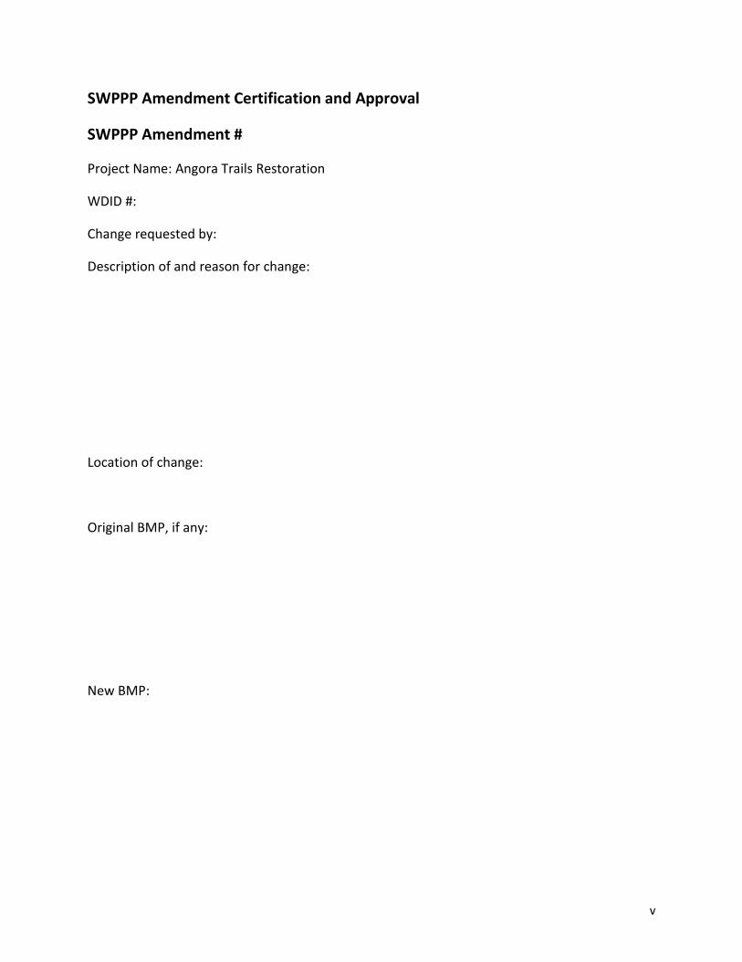
SWPPP Amendment Certification and Approval
SWPPP Amendment #
Project Name: Angora Trails Restoration
WDID #:
Change requested by:
Description of and reason for change:
Location of change:
Original BMP, if any:
New BMP:
vi
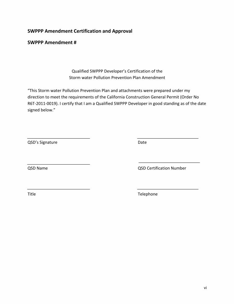
SWPPP Amendment Certification and Approval
SWPPP Amendment #
Qualified SWPPP Developer’s Certification of the
Storm water Pollution Prevention Plan Amendment
“This Storm water Pollution Prevention Plan and attachments were prepared under my
direction to meet the requirements of the California Construction General Permit (Order No
R6T-2011-0019). I certify that I am a Qualified SWPPP Developer in good standing as of the date
signed below.”
QSD’s Signature Date
QSD Name QSD Certification Number
Title Telephone

i
Appendix B – CASQA BMP Standard Specifications

ii

iii
Index of CASQA Fact Sheets*
WM-1 Material Delivery and Storage WM-2 Material Use WM-3 Stockpile Management WM-4 Spill Prevention and Control WM-5 Solid Waste Management WM-6 Hazardous Waste Management WM-9 Sanitary/Septic Waste Management EC-1 Scheduling EC-2 Preservation of Existing Vegetation EC-8 Wood Mulching EC-9 Earth Dikes and Drainage Swales EC-12 Stream Bank Stabilization EC-15 Soil Preparation-Roughening EC-16 Non-Vegetative Stabilization WE-1 Wind Erosion Control SE-1 Silt Fence SE-5 Check Dams SE-5 Fiber Rolls NS-1 Water Control and Conservation NS-2 Dewatering Operations NS-5 Clear Water Diversion NS-6 Illicit Connection and Illegal Discharge NS-8 Vehicle and Equipment Cleaning NS-9 Vehicle Equipment Fueling NS-10 Vehicle and Equipment Maintenance
*The CASQA fact sheets referenced above are not included in this document, but they will be availableon site during construction.

i

i
Appendix C – Engineering Plans and Specifications (EPS)
Index of sheets:
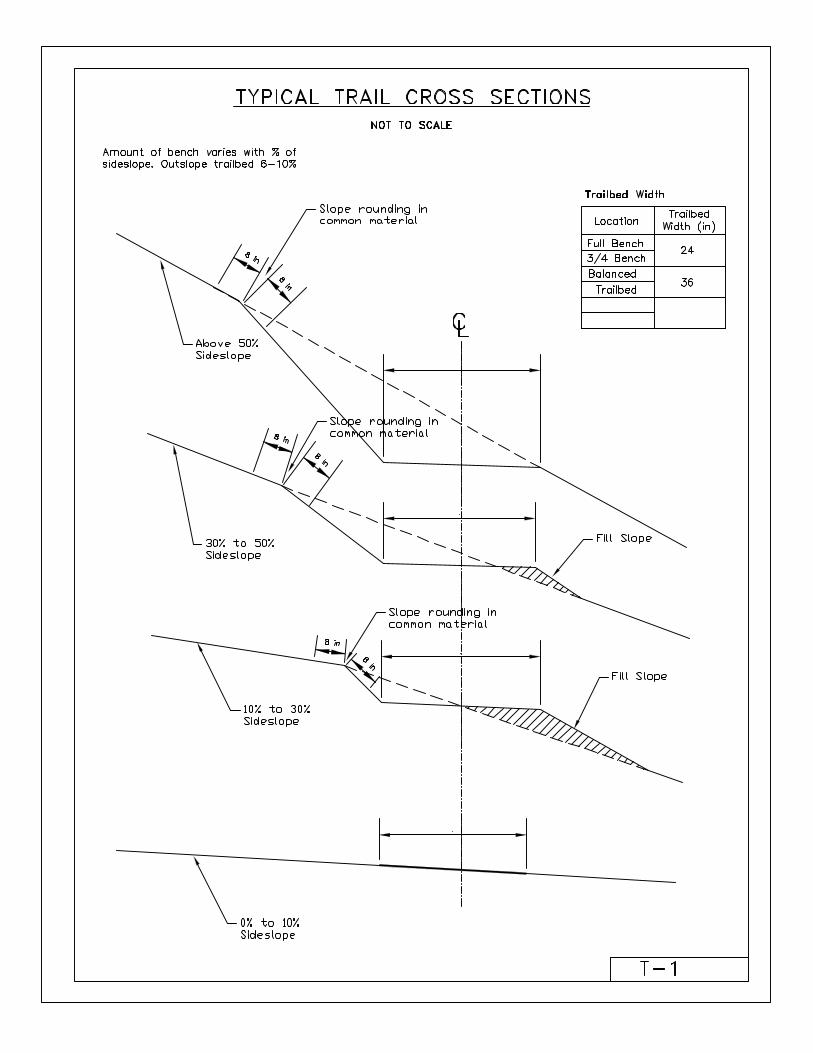
T1: Typical Trail Cross Sections
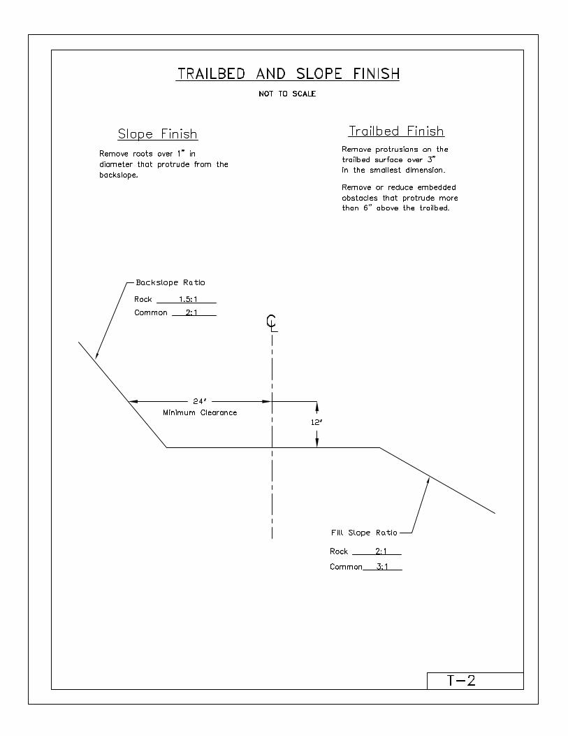
T2: Trailbed and Slope Finish
T3: Clearing Limits
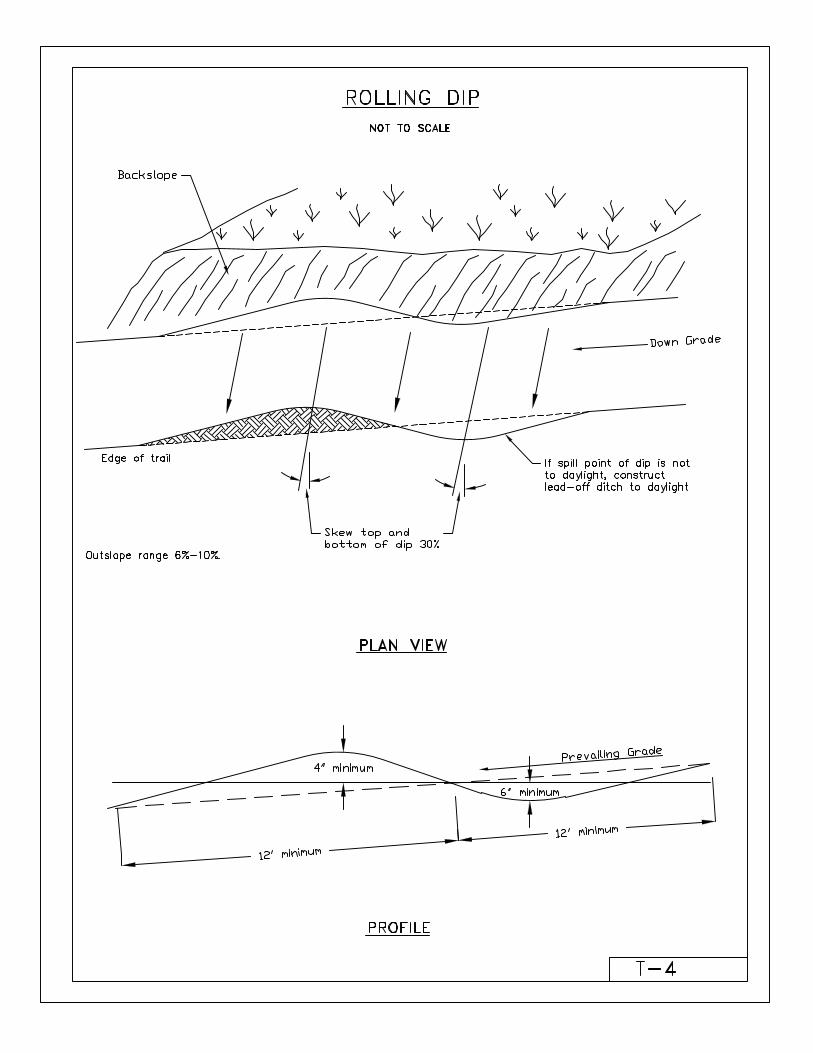
T4: Rolling Dip
T5: Rock Ford
T6: Causeway
T7: Check Dams
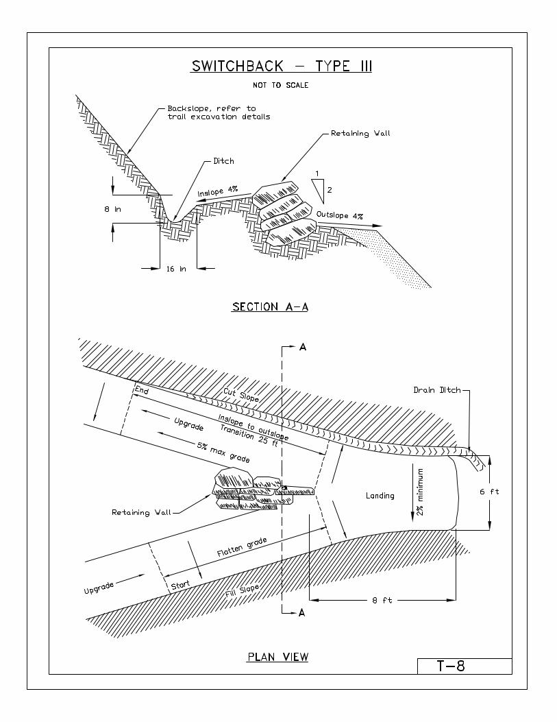
T8: Switchback
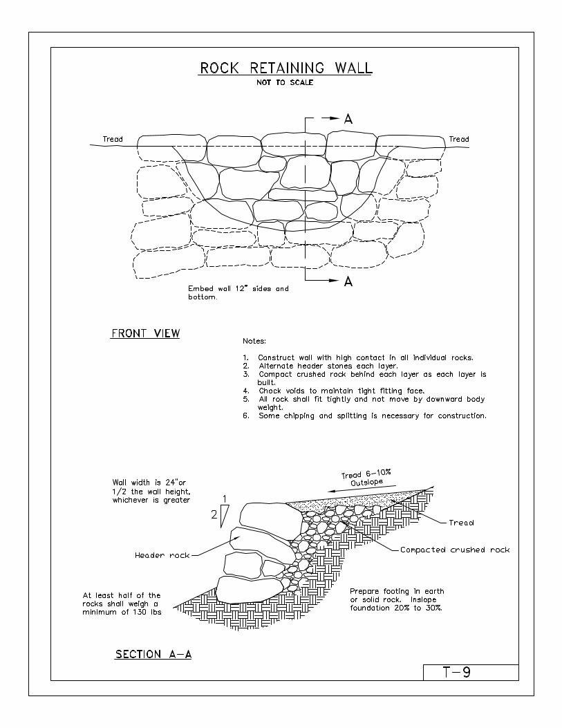
T9: Rock Retaining Wall
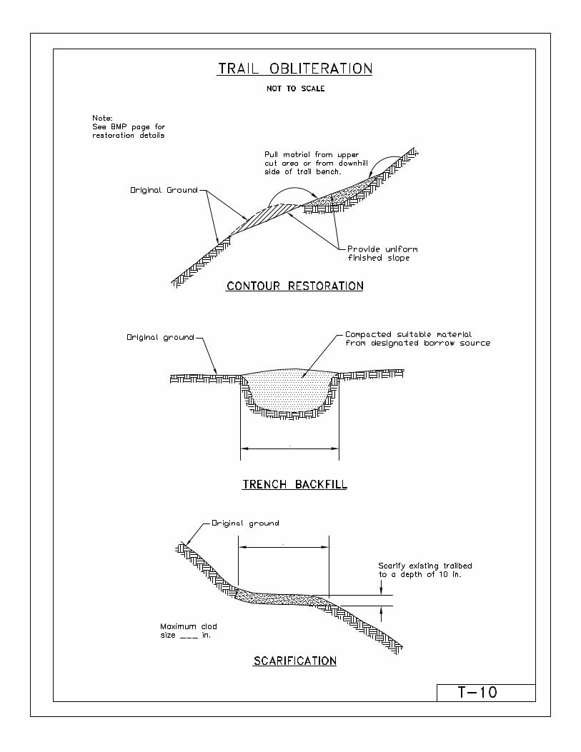
T10: Trail Obliteration
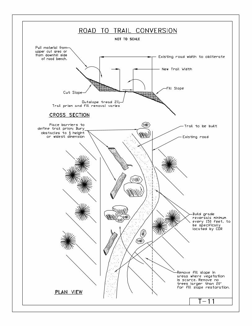
T11: Road to Trail Conversion
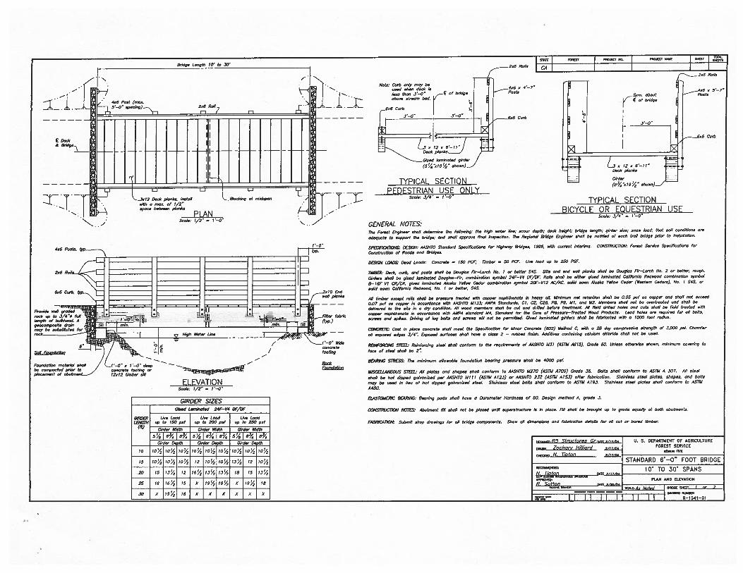
T12: Bridge Drawings A
T13: Bridge Drawings B

i

Bridge Length 10’ to .50’STATE 050tsr
— I PROJECT NO. I RAWEST NONE J 5115Cr
I
________________________________ ______________________________
Il-i
l0
Esdsell plsnks
=5
Filter febrls
- rein. I ro (t)’p.)
Wide
footstg
BELA
_i-/
406 Post (,seo.5’—0 sp0ChTg)__.,,, 206 Roil
E Dersk&
I—
2s6 RerIs LL
1 No/s Corn osiy moy beI “. used shes deok is 4u6 5 4—7
•less thee 3’—0 of bridge Posts
i_ I : 6:::
strosm bod.
— r1 ° °
‘—° 6o6 Cuth
m
___
-
4;ii,jGlodl todgtsl(5’/e’:rlO’4’ show,)
TYPICAL SECTION
Z°”Lgeook,egrndepee jI
Suslo; 1/2’ 1—0’‘5.
2x6 Rolls
406 5 5—7’rm. shout Posts
of bridge
656 Curb
456 Pests.
2s6 Rolls
6s6 Coth,
PEDESTRIAN USE ONLY
L351206.11 ::Desk plonks
Girder
(53//sI9/ shoss)
TYPIflAI SECTIoN
gesoonopssite Are/s 30 JSIl -
______________
moy be sobstitoted for ------.--
___________________
,sok y Higi, $tete LI,,.
6’Sell Foro,oJotles, E /
Fe,.o,dotlon ,notedel eholl I ‘—0’ o t’—O deepor
ELEVATIONSos/c; t/2’ 1—0”
Ssolo; 3/4” — I—C’
BICYCLE OR EQUESTRIAN USESssie; 5/4’ = 1—0”
GENERAL NOTES:The Forest Engineer shell determine the folluooisg; the high color lion; s505r depth; deCk height; bridge length; g,rder soon; onso boA; ttost eon send/ross or,,
odeqoote to support tho bridge; ond ohs/i opproore Tool inspoo/iOs. The Rep/snot Bridge Engineer shoP be sstifiod of oosh trod bsdge pnor Is ,nstsllshos.
SPECIFtC,4IIONSI DES/Gil; AASHTO Stosdord Speoifiootises for Higlssoy Bridgos, /996, ellIS ourrest interirno. C0NSrRUC17ON Forest Ssrviss Sposillss/i050 for
Cosotrostiee of Rssdo sod BrIdges.
DESIGN LOADSr Deed Leeds; Cssoroto = ISO PCi, limber = 50 PCF. Lire bed up to 250 PSF.
TIMB(Rr Desk, sorb, esd poots shell be Dosgbos Fir—Lerot, Ns. i or better $45. Sills sod end sell plosbs ohs/I be Doug/so Fir—Lomb No. 2 or boiler, ropeS.
Oirdero shell be gloed lommso/ed Doug/so—Fir, son,bisstiss symbol 24F—V4 OF/OF. Rolls sholl be either globe lgn,ineled Coliforeig Rodsosd uss,b,not,50 symbol
8— 16F Vt CR/CR. gloed lorninotod Aleoko folIos, Ceder soo,binstion symbol 20F—V12 AC/AC. solid sees .4iooks Ye/Iso Ceder (Woo/nm Coders), No. I S4S. or
solid sees Celifornie Redsood, No. I or bolter, S4S.
.411 timber esoept rolls shell be presssre frosted silk oopper nephtheoole is heery oil. Misilsom set re/es/iso shell be 0.05 psf Os sopper sod sholl not esseed
0.07 poF Os sopper is enooordenoe si/h AA5H1O 4113.5; AWPA Stsndordo, CI, CS, C29, PB, P9, III, end 112. Members eholl osi be orerlree/ed osd ohs/I be
delin.ered te the site in s dry oendition. .411 seed members ohs/I be out end drilled before tree/wrest. All field drilled holes esd rots shoP be field Ares/ed nell,
soppor nophttreeo/e is oossrdOnon silk AWPA s/osdoo’d M4, Sloedord fur lbs Core of Pressure—Foes/ed Wood Produsts. Leod hobo ore required for oil boIls,
sCreen ond spikes. Ow/sing of leg belts sod Morose sill not be permitted. Glued lommne/ed girders sholl be fobrbseled soilS o 1000 foot rodiks.
CONCRE7D/ Cost in pbeoe ,oonomte shell meet the Spesilisetion for Miser Conurete (602) Method C, sith e 28 doy opressi strength of 3,000 p5,. Chs,nfer
oil esp000d edges 3/4’: Esposed osos,,o shell here e oboe 2 — ,ubbed finish. Additiuso oooteining sslulum ohlorido ohs/I sot be used.
REINFORCING S7$E’L, Reinforsiog stool eholl 005ferm to the mqsiromeets of MENlO M3I (ASIM A615). Grode 60. Unless otholwise shoss. misimum sororisg to
feoe of steel shell be 2’:
BEARING $111555 The misimum ollooeble fosndetiss Scoring pr055sre shell be 4000 psf.
MISCELLANEOUS SIDlE, All p10100 sod shopes shoP osnforn, to AASHFD U270 (ASTM A709) Grode .56. 601/0 shell sosform /0 ASII4 A 307. All 0/nob
ohs/I be hot dipped gebrenised per AASI170 MIII (ASTM A 123) or A4SHTO 232 (ASTM A 153) of/er fobs/se/iso. Sloinleos s/osl p/s/es, shopsu, sod bells
moy be seed in lieu of hot dipped gebsonired s/eeL Steisl000 steel bolts shell oooferm to ASTM A 193. Stoinless s/eel plo/os shell osoforro to .4571,4
A480.
ELASTOMERIC BEARING, 8eso/og pods shell here 5 Osrorno/or Hord0005 of 60. 005igs method A, grede 3.
CONSTRUCIION NOTES, Ahstmon/ fill 55511 sot be pissed until soperstmslsro is is plose. Fill shell be brssghl up Is grede equolly 01 both obs/mests.
FA8RIC,4 lION; Submit shop drosings fer oil bridge oomponon/o. Shoe. oll dinoossiens ond fobriselisn dolsilo for oil sot or bored timber.
GIRDER SIZESGtsed Lsrolneted 24F—V4 OF/OF
GIRDER Lire Lobe Use Lood Lire Lood1.5110tH sp to ISO pef sp to 200 psi op to 250 psf“ Girder Width Girder WIdth Girder Width
5/oI63%i83/454i6’%i85/45’oi034iP’/4Girder Don/h Girder Do lb Girder- Do th
10 io’/ bY2 1O’/ 10’% t0i4 IO!4 bY2 I0!/ I04
15 IO’/2 IOu2 IO’/o 12 iou4 IO’4 iiY2 72 iou4
20 15 I3u4 12 16u4 i3iY2 I3u4 79 II 131/2
25 18 I6’/ 15 5 I9u/2 I6u4 X io!4 18
30 S I94 ts x xix x x x
sR5 Structures Gr.o.gs/orth Ti. S. DEPARTMENT OF AGRICULTURE
rmeon Zochori’ Hi/lisfd FOREST SERV/CEc/MON 555
w,os N. TIDEOI7STANDARD 6’—O” FOOT BRIDGE
eoPRONRs,41 CiIs
10’ TO 30’ SPANS
PLAN AND ELEVATION
loosE NAICT,_CCC
iNNsONu 555055
6—1541—01
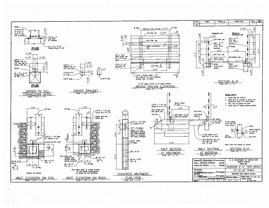
2—50d Spikosneck side (let.
°°
\ _._L rn//post
8/se dg.._
tinter Crsb end Roil/hg ,,et sheon.
SECTION A—ASuolo. 3/4” 7—0”
Gi,dnr
vvJ60
Troeted Bong, F7 sill
4 t/2”
2 7/4” 2 7/4”
5/8”ø 0 1”Slottod hole for
ohs/
-
?2et2e9’—O”
GIRDER TO SILLCONNECTION DETAIL
Svol.r I 1/2””” 7—0”
4 7/2”
5/6”ø e I”Slotted hole for —
_________
tId? I*GIRDER BRACKET
508/c, I ‘/2” —
(gilder e,dlh 4’ 5)belts s/ sot end melleoble
.voohero (h’p. sO bells)
(4—6” Height sheen, 3—6” height sirs//er)
BRIDGE RAILING ELEVATIONSos/er 2/4”
SECTION B—BSee/er 3/i” = 7—0”
N0765i
I. Poole oholl be cool/eel
2. Rsils sholl be perotel Is goods codcontinuous over 2 or morn pe,s1s.
3, Only son roil op/ice pm pest.
4. Posts ohs/I lit lightly egsinsl girders.
0 7—0” EoItor,’ sosber & set
j/2” e W (girdereo’dth) C 0’—4’4”Oeotosnsrle boss/hgpsi 60d herdoss,Seven to eencrelose/tb opeey sdheoive.
.,.S>nnm. shoot
I
—4CflMCPETE_ABUTkAF1’JT
PLAN VIEWSee/hr 3/4” = 1—0’
Note, When depth of footing eeeeodoIC” uses/mOor reinfereemoot0056500 for no/I conditions.
_f4(let. 9)
HALF SECTIONAT ABUTMENT
See/or 3/4” = 1—0”
HALF SECTIONAT MIDSPANSen/or 3/4” 7—0”
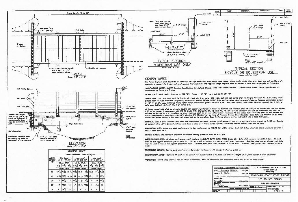
Bridge Length 10’ to .50’STATE 050tsr
— I PROJECT NO. I RAWEST NONE J 5115Cr
I
________________________________ ______________________________
Il-i
l0
Esdsell plsnks
=5
Filter febrls
- rein. I ro (t)’p.)
Wide
footstg
BELA
_i-/
406 Post (,seo.5’—0 sp0ChTg)__.,,, 206 Roil
E Dersk&
I—
2s6 RerIs LL
1 No/s Corn osiy moy beI “. used shes deok is 4u6 5 4—7
•less thee 3’—0 of bridge Posts
i_ I : 6:::
strosm bod.
— r1 ° °
‘—° 6o6 Cuth
m
___
-
4;ii,jGlodl todgtsl(5’/e’:rlO’4’ show,)
TYPICAL SECTION
Z°”Lgeook,egrndepee jI
Suslo; 1/2’ 1—0’‘5.
2x6 Rolls
406 5 5—7’rm. shout Posts
of bridge
656 Curb
456 Pests.
2s6 Rolls
6s6 Coth,
PEDESTRIAN USE ONLY
L351206.11 ::Desk plonks
Girder
(53//sI9/ shoss)
TYPIflAI SECTIoN
gesoonopssite Are/s 30 JSIl -
______________
moy be sobstitoted for ------.--
___________________
,sok y Higi, $tete LI,,.
6’Sell Foro,oJotles, E /
Fe,.o,dotlon ,notedel eholl I ‘—0’ o t’—O deepor
ELEVATIONSos/c; t/2’ 1—0”
Ssolo; 3/4” — I—C’
BICYCLE OR EQUESTRIAN USESssie; 5/4’ = 1—0”
GENERAL NOTES:The Forest Engineer shell determine the folluooisg; the high color lion; s505r depth; deCk height; bridge length; g,rder soon; onso boA; ttost eon send/ross or,,
odeqoote to support tho bridge; ond ohs/i opproore Tool inspoo/iOs. The Rep/snot Bridge Engineer shoP be sstifiod of oosh trod bsdge pnor Is ,nstsllshos.
SPECIFtC,4IIONSI DES/Gil; AASHTO Stosdord Speoifiootises for Higlssoy Bridgos, /996, ellIS ourrest interirno. C0NSrRUC17ON Forest Ssrviss Sposillss/i050 for
Cosotrostiee of Rssdo sod BrIdges.
DESIGN LOADSr Deed Leeds; Cssoroto = ISO PCi, limber = 50 PCF. Lire bed up to 250 PSF.
TIMB(Rr Desk, sorb, esd poots shell be Dosgbos Fir—Lerot, Ns. i or better $45. Sills sod end sell plosbs ohs/I be Doug/so Fir—Lomb No. 2 or boiler, ropeS.
Oirdero shell be gloed lommso/ed Doug/so—Fir, son,bisstiss symbol 24F—V4 OF/OF. Rolls sholl be either globe lgn,ineled Coliforeig Rodsosd uss,b,not,50 symbol
8— 16F Vt CR/CR. gloed lorninotod Aleoko folIos, Ceder soo,binstion symbol 20F—V12 AC/AC. solid sees .4iooks Ye/Iso Ceder (Woo/nm Coders), No. I S4S. or
solid sees Celifornie Redsood, No. I or bolter, S4S.
.411 timber esoept rolls shell be presssre frosted silk oopper nephtheoole is heery oil. Misilsom set re/es/iso shell be 0.05 psf Os sopper sod sholl not esseed
0.07 poF Os sopper is enooordenoe si/h AA5H1O 4113.5; AWPA Stsndordo, CI, CS, C29, PB, P9, III, end 112. Members eholl osi be orerlree/ed osd ohs/I be
delin.ered te the site in s dry oendition. .411 seed members ohs/I be out end drilled before tree/wrest. All field drilled holes esd rots shoP be field Ares/ed nell,
soppor nophttreeo/e is oossrdOnon silk AWPA s/osdoo’d M4, Sloedord fur lbs Core of Pressure—Foes/ed Wood Produsts. Leod hobo ore required for oil boIls,
sCreen ond spikes. Ow/sing of leg belts sod Morose sill not be permitted. Glued lommne/ed girders sholl be fobrbseled soilS o 1000 foot rodiks.
CONCRE7D/ Cost in pbeoe ,oonomte shell meet the Spesilisetion for Miser Conurete (602) Method C, sith e 28 doy opressi strength of 3,000 p5,. Chs,nfer
oil esp000d edges 3/4’: Esposed osos,,o shell here e oboe 2 — ,ubbed finish. Additiuso oooteining sslulum ohlorido ohs/I sot be used.
REINFORCING S7$E’L, Reinforsiog stool eholl 005ferm to the mqsiromeets of MENlO M3I (ASIM A615). Grode 60. Unless otholwise shoss. misimum sororisg to
feoe of steel shell be 2’:
BEARING $111555 The misimum ollooeble fosndetiss Scoring pr055sre shell be 4000 psf.
MISCELLANEOUS SIDlE, All p10100 sod shopes shoP osnforn, to AASHFD U270 (ASTM A709) Grode .56. 601/0 shell sosform /0 ASII4 A 307. All 0/nob
ohs/I be hot dipped gebrenised per AASI170 MIII (ASTM A 123) or A4SHTO 232 (ASTM A 153) of/er fobs/se/iso. Sloinleos s/osl p/s/es, shopsu, sod bells
moy be seed in lieu of hot dipped gebsonired s/eeL Steisl000 steel bolts shell oooferm to ASTM A 193. Stoinless s/eel plo/os shell osoforro to .4571,4
A480.
ELASTOMERIC BEARING, 8eso/og pods shell here 5 Osrorno/or Hord0005 of 60. 005igs method A, grede 3.
CONSTRUCIION NOTES, Ahstmon/ fill 55511 sot be pissed until soperstmslsro is is plose. Fill shell be brssghl up Is grede equolly 01 both obs/mests.
FA8RIC,4 lION; Submit shop drosings fer oil bridge oomponon/o. Shoe. oll dinoossiens ond fobriselisn dolsilo for oil sot or bored timber.
GIRDER SIZESGtsed Lsrolneted 24F—V4 OF/OF
GIRDER Lire Lobe Use Lood Lire Lood1.5110tH sp to ISO pef sp to 200 psi op to 250 psf“ Girder Width Girder WIdth Girder Width
5/oI63%i83/454i6’%i85/45’oi034iP’/4Girder Don/h Girder Do lb Girder- Do th
10 io’/ bY2 1O’/ 10’% t0i4 IO!4 bY2 I0!/ I04
15 IO’/2 IOu2 IO’/o 12 iou4 IO’4 iiY2 72 iou4
20 15 I3u4 12 16u4 i3iY2 I3u4 79 II 131/2
25 18 I6’/ 15 5 I9u/2 I6u4 X io!4 18
30 S I94 ts x xix x x x
sR5 Structures Gr.o.gs/orth Ti. S. DEPARTMENT OF AGRICULTURE
rmeon Zochori’ Hi/lisfd FOREST SERV/CEc/MON 555
w,os N. TIDEOI7STANDARD 6’—O” FOOT BRIDGE
eoPRONRs,41 CiIs
10’ TO 30’ SPANS
PLAN AND ELEVATION
loosE NAICT,_CCC
iNNsONu 555055
6—1541—01
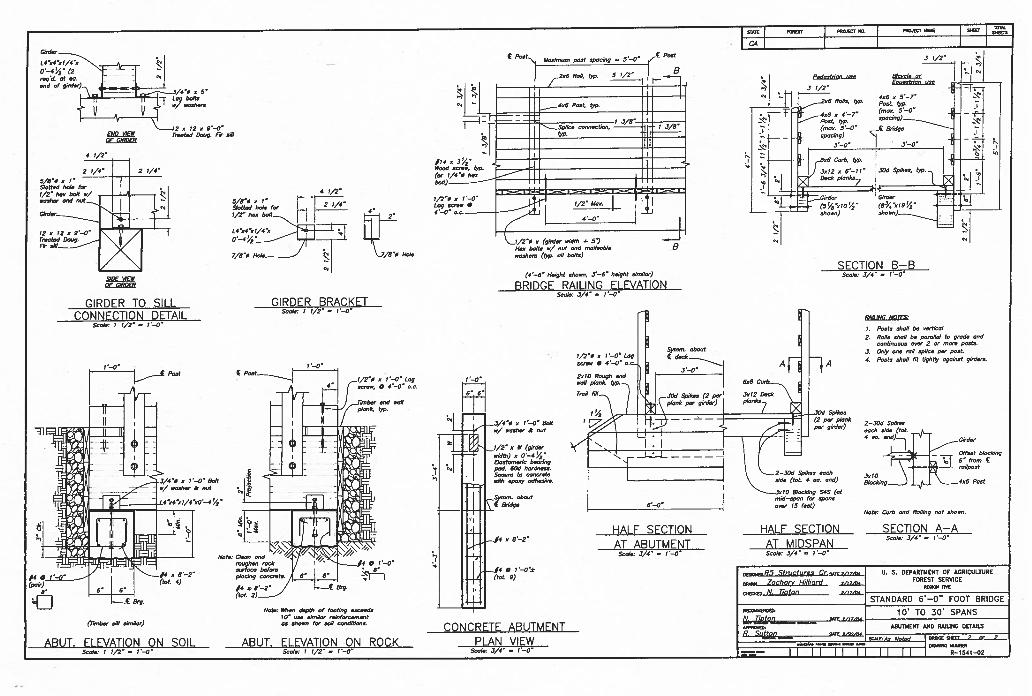
2—50d Spikosneck side (let.
°°
\ _._L rn//post
8/se dg.._
tinter Crsb end Roil/hg ,,et sheon.
SECTION A—ASuolo. 3/4” 7—0”
Gi,dnr
vvJ60
Troeted Bong, F7 sill
4 t/2”
2 7/4” 2 7/4”
5/8”ø 0 1”Slottod hole for
ohs/
-
?2et2e9’—O”
GIRDER TO SILLCONNECTION DETAIL
Svol.r I 1/2””” 7—0”
4 7/2”
5/6”ø e I”Slotted hole for —
_________
tId? I*GIRDER BRACKET
508/c, I ‘/2” —
(gilder e,dlh 4’ 5)belts s/ sot end melleoble
.voohero (h’p. sO bells)
(4—6” Height sheen, 3—6” height sirs//er)
BRIDGE RAILING ELEVATIONSos/er 2/4”
SECTION B—BSee/er 3/i” = 7—0”
N0765i
I. Poole oholl be cool/eel
2. Rsils sholl be perotel Is goods codcontinuous over 2 or morn pe,s1s.
3, Only son roil op/ice pm pest.
4. Posts ohs/I lit lightly egsinsl girders.
0 7—0” EoItor,’ sosber & set
j/2” e W (girdereo’dth) C 0’—4’4”Oeotosnsrle boss/hgpsi 60d herdoss,Seven to eencrelose/tb opeey sdheoive.
.,.S>nnm. shoot
I
—4CflMCPETE_ABUTkAF1’JT
PLAN VIEWSee/hr 3/4” = 1—0’
Note, When depth of footing eeeeodoIC” uses/mOor reinfereemoot0056500 for no/I conditions.
_f4(let. 9)
HALF SECTIONAT ABUTMENT
See/or 3/4” = 1—0”
HALF SECTIONAT MIDSPANSen/or 3/4” 7—0”

i
Appendix D - Visual Monitoring/BMP Inspection Form

ii
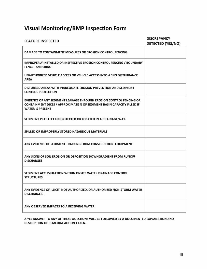
iii
Visual Monitoring/BMP Inspection Form
FEATURE INSPECTED DISCREPANCY DETECTED (YES/NO)
DAMAGE TO CONTAINMENT MEASURES OR EROSION CONTROL FENCING
IMPROPERLY INSTALLED OR INEFFECTIVE EROSION CONTROL FENCING / BOUNDARY FENCE TAMPERING
UNAUTHORIZED VEHICLE ACCESS OR VEHICLE ACCESS INTO A “NO DISTURBANCE AREA
DISTURBED AREAS WITH INADEQUATE EROSION PREVENTION AND SEDIMENT CONTROL PROTECTION
EVIDENCE OF ANY SEDIMENT LEAKAGE THROUGH EROSION CONTROL FENCING OR CONTAINMENT DIKES / APPROXIMATE % OF SEDIMENT BASIN CAPACITY FILLED IF WATER IS PRESENT
SEDIMENT PILES LEFT UNPROTECTED OR LOCATED IN A DRAINAGE WAY.
SPILLED OR IMPROPERLY STORED HAZARDOUS MATERIALS
ANY EVIDENCE OF SEDIMENT TRACKING FROM CONSTRUCTION EQUIPMENT
ANY SIGNS OF SOIL EROSION OR DEPOSITION DOWNGRADIENT FROM RUNOFF DISCHARGES
SEDIMENT ACCUMULATION WITHIN ONSITE WATER DRAINAGE CONTROL STRUCTURES.
ANY EVIDENCE OF ILLICIT, NOT AUTHORIZED, OR AUTHORIZED NON-STORM WATER DISCHARGES.
ANY OBSERVED IMPACTS TO A RECEIVING WATER
A YES ANSWER TO ANY OF THESE QUESTIONS WILL BE FOLLOWED BY A DOCUMENTED EXPLANATION AND DESCRIPTION OF REMEDIAL ACTION TAKEN.
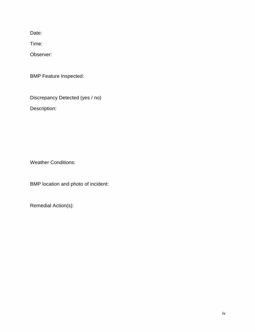
iv
Date:
Time:
Observer:
BMP Feature Inspected:
Discrepancy Detected (yes / no)
Description:
Weather Conditions:
BMP location and photo of incident:
Remedial Action(s):

i
Appendix E - Rain Event Action Plan Template

i
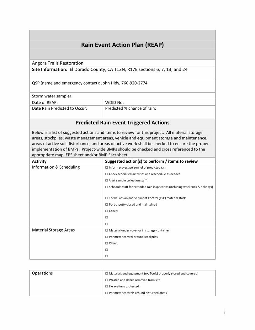
i
Rain Event Action Plan (REAP)
Angora Trails Restoration
Site Information: El Dorado County, CA T12N, R17E sections 6, 7, 13, and 24
QSP (name and emergency contact): John Hidy, 760-920-2774
Storm water sampler:
Date of REAP: WDID No:
Date Rain Predicted to Occur: Predicted % chance of rain:
Predicted Rain Event Triggered Actions
Below is a list of suggested actions and items to review for this project. All material storage areas, stockpiles, waste management areas, vehicle and equipment storage and maintenance, areas of active soil disturbance, and areas of active work shall be checked to ensure the proper implementation of BMPs. Project-wide BMPs should be checked and cross referenced to the appropriate map, EPS sheet and/or BMP Fact sheet.
Activity Suggested action(s) to perform / items to review
Information & Scheduling □ Inform project personnel of predicted rain
□ Check scheduled activities and reschedule as needed
□ Alert sample collection staff
□ Schedule staff for extended rain inspections (including weekends & holidays)
□ Check Erosion and Sediment Control (ESC) material stock
□ Port-a-potty closed and maintained
□ Other:
□
□
Material Storage Areas □ Material under cover or in storage container
□ Perimeter control around stockpiles
□ Other:
□
□
Operations □ Materials and equipment (ex. Tools) properly stored and covered)
□ Wasted and debris removed from site
□ Excavations protected
□ Perimeter controls around disturbed areas

ii
□ Other:
□
□
Site ESC BMPs □ Site perimeter controls in place
□ Temporary erosion controls deployed
□ Temporary perimeter controls deployed around disturbed areas and
stockpiles
□ Other:
□
□
Spills & Drips
□ All incident spills and drips contained and cleaned
□ Drip pans emptied
□ Other:
□
□
Other/ Discussion/ Diagrams
Attach a printout of the weather forecast from the NOAA website to the REAP
I certify under penalty of law that this Rain Event Action Plan (REAP) will be performed in accordance with the General Permit by me
or under my direction or supervision in accordance with a system designed to assure that qualified personnel properly gathered and
evaluated the information submitted.
Qualified SWPPP Practitioner (QSP) Date:

i
Appendix F – Permit Documents

ii
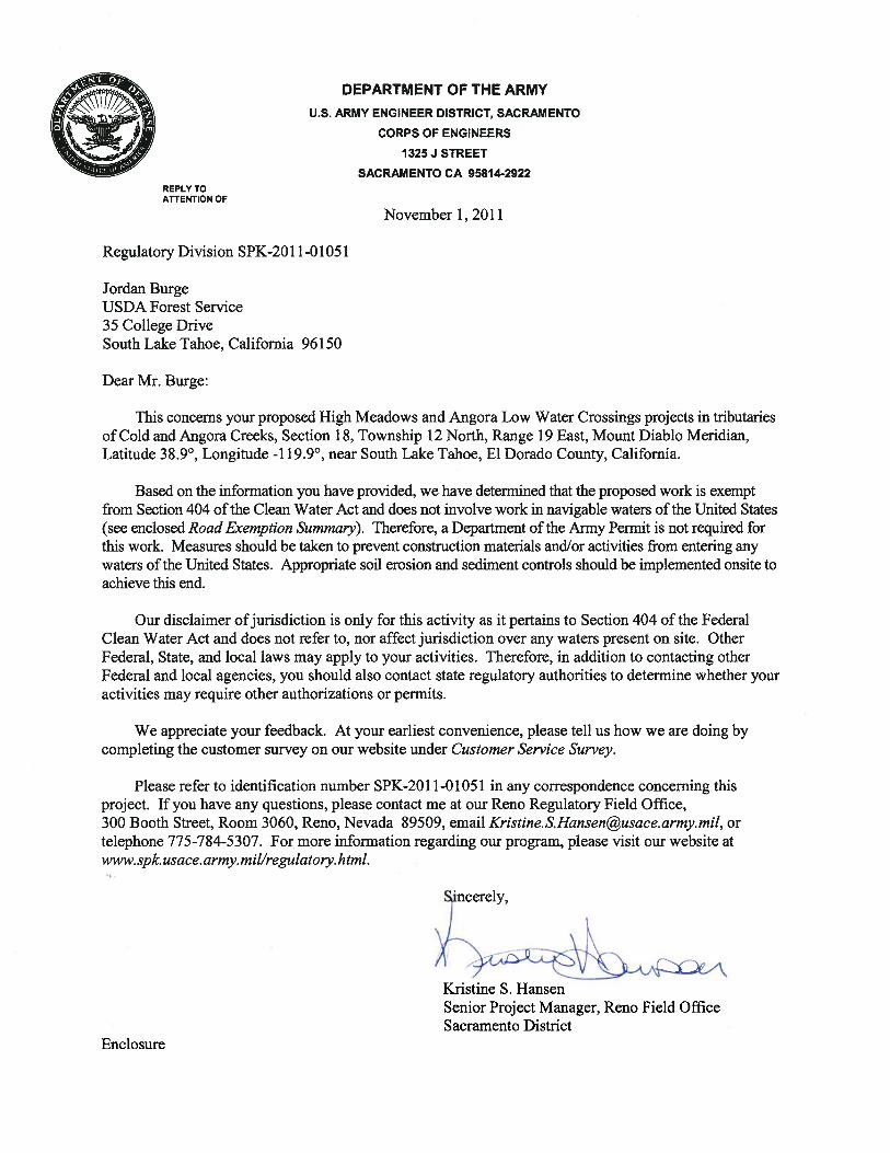

iv

From: Blackford, Jordon SPKTo: Burge, Jordan -FSSubject: RE: 404 Exemption, ID number SPK-2011-01051Date: Wednesday, January 23, 2013 11:03:58 AM
Jordan,
I have reviewed the information you submitted to Kristine Hansen regardingthe change in the scope of work for this project. It appears this work isstill exempt from Section 404 of the Clean Water Act under the RoadExemption for forest roads. As long as the flow and circulation of thestream channel is not altered, this work does not require a permit.
Thank you,
Jordon BlackfordSCEP, Student Trainee (Biology)US Army Corps of Engineers, Sacramento DistrictReno Regulatory Field Office300 Booth Street, Room 3050Reno, NV 89509-1361(775) 784-5305 fax: (775) [email protected]
We want to hear from you! Submit a customer service survey form.http://per2.nwp.usace.army.mil/survey.html
Need information on the Regulatory Program?www.spk.usace.army.mil/missions/regulatory.aspx


i
Appendix G – Training Logs

ii

iii
Personnel Training Log
Storm water Management Training Log and Documentation
Project Name:
WDID #:
Storm water Management Topic: (circle as appropriate)
Erosion Control Sediment Control Wind Erosion Control Storm water Sampling
Non-Storm water Management Waste Management and Materials Pollution Control
Storm water Sampling
Specific Training Objective:
Location: Date:
Instructor: Telephone:
Course Length (hrs):
Attendee Roster
Name of Personnel Name of Personnel Name of Personnel
As needed, add proof of external training.

i

i
Appendix H – Prohibition Exemption Information

ii

iii
From Attachment F, Waste Discharge Prohibition Information for Activities in Stream
Environment Zones and Floodplains of the Lake Tahoe Hydrologic Unit, of the Tahoe
Construction Permit R6T-2011-0019
Chapter 5, section 5.7 of the Basin Plan provides that exemptions may be granted in floodplains
under certain categories. The Angora Trail Restoration Project fits most appropriately under the
following category:
1. Public outdoor recreational facilities if: (a) the project is a necessary part of a public
agency’s long range plans for public outdoor recreation; (b) the project, by its very
nature, must be sited in a floodplain; (c) there is no feasible alternative that would
reduce the extent of encroachment in a floodplain; and (d) the impacts on the
floodplain are minimized.
Chapter 5, section 5.8 of the Basin Plan provides that exemptions may be granted in SEZs under
certain categories. The Angora Trail Restoration Projects fits most appropriately under the
following category:
1. Public Outdoor Recreation facilities, when all of the following findings can be made:
(a) the project, by its very nature, must be sited in an SEZ; (b) there is no feasible
alternative that would reduce the extent of SEZ encroachment; (c) impacts are fully
mitigated; and (d) SEZs are restored in an amount 1.5 times the area of SEZ
disturbed or developed for the project.
The following answers Section 5.8 of the Basin Plan, which includes all necessary information to
answer Section 5.7 of the Basin Plan.
1. (a) the project, by its very nature, must be sited in an SEZ
The entire transportation system within the Angora burn area was extensively analyzed
within the Environmental Assessment for the Angora Fire Restoration Project (Angora
EA). Each trail alignment was located in the best capable lands possible. Currently, there
are approximately 18,630 square feet of unclassified trails located within SEZs. This
project will relocate and eliminate over 15,130 square feet of those located within SEZs
(see Table H1 for calculations). Only the necessary alignments were kept within SEZs to
connect the entire transportation system, including the trail bridge crossing over Angora
Creek. This specific crossing location will have the least impact along Angora Creek.

iv
1. (b) there is no feasible alternative that would reduce the extent of SEZ encroachment
Alternatives were extensively analyzed within the Angora EA. All trail work was examined,
and was determined to minimize SEZ coverage by decommissioning unneeded routes and
locating needed routes in areas of high capability soils. New alignments were generally
chosen on existing disturbance whenever resources could be sufficiently protected. Trail
alignments were generally located away from sensitive areas to minimize impacts to
stream courses. When construction or improvement of trails in wet areas cannot be
avoided, proper Best Management Practices (BMPs) have been identified and will be
utilized to mitigate impacts.
The trail bridge crossing over Angora Creek is an identified area where the alignment will
travel through SEZ. This particular location was chosen for several reasons: it will have
the least impact to SEZ, the creek is narrow and unbraided (unlike most nearby upstream
and downstream locations), and minimal approach work will be required. A short span
bridge, less than 20 feet in length, has been selected for the crossing. This relatively short
span is an economical solution for a small crossing. Although the abutments will not span
outside all riparian vegetation, its small size and simple construction will minimize
disturbance and fully meet recreational needs. While a larger bridge may pass 100-year
storm flows, it would cause far more disturbance (larger area of excavation, imported fill
and riprap armoring, larger equipment for installation, and larger approaches, resulting
in more fill and impervious area), and would be much more expensive. A small bridge was
also chosen over a ford. Angora Creek can carry high flows, and a ford may be dangerous
in these conditions. And as is common in similar locations, users may cause more damage
near the crossing to get across the creek (i.e. crossing logs and debris that plug the
channel, create ponding, and erode the banks).
1. (c) impacts are fully mitigated
Mitigation measures for this project include Angora EA BMPs, as well as with other
permanent BMPs. Temporary and permanent BMPs are described in Appendix A of the
Angora EA and in the engineering drawings (Appendix C). Each applicable BMP is
described below.
BMPs from Appendix A of the Angora EA (these BMPs were developed specifically for
road construction, but will apply to trail construction as well):
BMP 2-1 General Guidelines for the Location and Design of Roads
BMP 2-2 Erosion Control Plan

v
BMP 2-3 Timing of Construction Activities
BMP 2-4 Stabilization of Road Slope Surfaces
BMP 2-5 Road Slope Stabilization Construction Practices
BMP 2-6 Dispersion of Subsurface Drainage from Cut and Fill Slopes
BMP 2-7 Control of Road Drainage
BMP 2-9 Timely Erosion Control Measures on Incomplete Roads & Stream Crossings
BMP 2-10 Construction of Stable Embankments
BMP 2-11 Control of sidecast material during construction and maintenance
BMP 2-12 Servicing and refueling equipment
BMP 2-13 Control of Construction and Maintenance activities adjacent to SMZs
BMP 2-14 Controlling in-channel excavation
BMP 2-15 Diversion of flows around construction sites
BMP 2-16 Stream crossings on temporary roads
BMP 2-19 Disposal of right-of-way and roadside debris
BMP 2-21 Water source development consistent with water quality protection
BMP 2-22 Maintenance of Roads
BMP 2-26 Decommissioning of Roads
Permanent BMPs within engineering plans (Appendix C):
T4: Rolling Dip
T5: Rock Ford
T6: Causeway
T7: Check Dams
T8: Switchback
T9: Rock Retaining Wall
T10: Trail Obliteration
T11: Road to Trail Conversion
Temporary BMPs are discussed extensively in Section III of this SWPPP, and all
identified CASQA specifications are listed in Appendix B.

vi
1. (d) SEZs are restored in an amount 1.5 times the area of SEZ disturbed or developed for
the project
See Table H1 for calculations and extensive information regarding each trail to be
constructed and restored. There will be minimal SEZ disturbance for this project. Most
new trails located within SEZs were existing non-system, user-created routes. The LTBMU
will adopt these sections of trail and build them specifically for wet areas. When
construction is complete, there will be approximately 3500 square feet of trails located
within SEZs. This project will eliminate over 15,130 square feet of trails located within
SEZs.
The information above answers questions specific to Attachment F of the Tahoe Construction
Permit. The information below specifically describes trail construction within wet areas.
When practical, the trail alignment will always be located away from wet areas. When a trail
alignment must be located in a wet area, a causeway (see Appendix C, Angora Trail
drawings) will be constructed. Four inches of clean rock base will be placed within the
travelway, and native material will be placed and compacted on top. Log or rock retainers
will be placed on the alignment borders to contain the material. Causeways will be built in
flat areas, where there is typically little or no surface flow. A rock face drainage break will
be constructed where flow is impounded. The only exception to causeway construction in
wet areas is when the trail crosses a defined channel, an in these situations, a ford or bridge
will be used (see Figure 2 for specific locations).
When a trail alignment crosses an intermittent or ephemeral channel, the channel will be
stabilized and maintained to convey water across the trail. In most instances, large rocks
embedded into the banks will stabilize the crossing sufficiently. In instances where channel
is more defined, or the flows are obviously higher, a rock ford will be constructed (see
Appendix C, Angora Trail drawings). Rock ford construction has been identified near Tahoe
Mountain Road and off of Pyramid Circle (see Figures 2, 4, and 5 for specific locations).
These specific locations have well defined channels and have the potential for higher flows
and more erosion, and ford construction will give them more stabilization. Native material
will be used for all ford construction. Fords will be constructed when the channel is dry, and
will be built with hand tools or a mini excavator. If the fords are constructed with a mini
excavator, they will access the construction site from Forest Service Roads and up the
constructed approach trail. Trails will also be obliterated in wet areas. If the trail has started
to restore itself (i.e. vegetation has started to grow and the trail is stabilized) minimal

vii
disturbance will be made. Other trails will be recontoured, stabilized, and camouflaged with
natural materials.
A trail bridge will be constructed across Angora Creek (see Figure 2 and Figure 3 for the
specific location). Currently, there are large logs and debris within the streambed that have
created ponding and modified the original alignment. This organic debris will be removed,
and two large rock abutments will be placed with minimal disturbance to the creek.
Approach and abutment construction will be the only disturbance within the creek, and is
only expected to take 2 days. The bridge superstructure (deck, rail, and finish work)
construction will not have any effect on the creek. There will be no concrete used in the
construction of the bridge. All treated wood materials will follow the treatment
requirements found in “Best Management Practices for the Use of Treated Wood in Aquatic
Environments,” published by the Western Wood Preservers Association. Native material or
imported, clean material will be used for the approaches and stream banks. Stone will be
used to build up the banks and allow for 24 inches of clearance from the creek bed. Native
material and stone will be used to backfill and armor the abutments. The design has
considered the floodplain, and the structure will not impact aquatic species. Construction
will take place during low or no flow. The clear water diversion BMP has been identified
(Appendix B, CASQA specifications) and will be utilized if there is flow during construction.
See Section III.D. Dewatering and Diversion Plan Narrative for more diversion information.
Additional trail bridge information:
Volume of excavation: 10 CY
Area of SEZ disturbance: 150 SF
The rock abutments will be approximately 3 feet wide, and will be installed 12
inches below grade. They will be held in place by a check wall (pinned by
boulders on each side).
The bridge will be pinned to the abutments
The bridge is not designed to clear a 100-year storm. During a large storm, the
bridge will lift and wash downstream, leaving the abutments in place. This
simplistic and economical bridge construction method will allow the
superstructure to be rebuilt on top of the abutments after a large storm event.
The bridge will be constructed using hand tools and a mini excavator.
Equipment will not cross the creek. The excavator will access the site on Forest
Service system roads and trails.

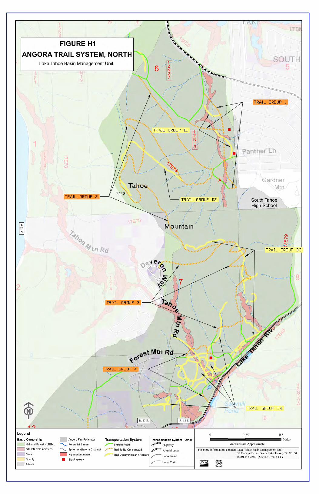

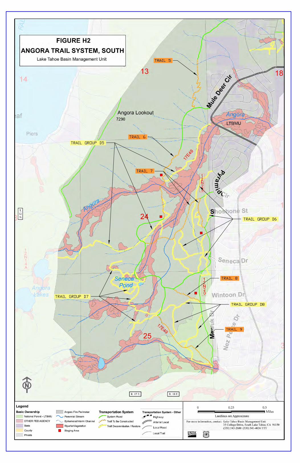
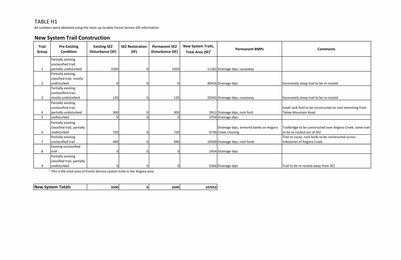
TABLE H1All numbers were obtained using the most up-to-date Forest Service GIS information
New System Trail Construction
Trail
Group
Pre-Existing
Condition
Existing SEZ
Disturbance (SF)
SEZ Restoration
(SF)
Permanent SEZ
Disturbance (SF)
New System Trails,
Total Area (SF)1 Permanent BMPs Comments
1
Partially existing
unclassified trail,
partially undisturbed 1920 0 1920 11182 Drainage dips, causeway
2
Partially existing
classified trail, mostly
undisturbed 0 0 0 40416 Drainage dips Excessively steep trail to be re-routed
3
Partially existing
unclassified trail,
mostly undisturbed 120 0 120 20342 Drainage dips, causeway Excessively steep trail to be re-routed
4
Partially existing
unclassified trail,
partially undisturbed 300 0 300 3912 Drainage dips, rock ford
Small rock ford to be constructed on trail stemming from
Tahoe Mountain Road
5 undisturbed 0 0 0 5754 Drainage dips
6
Partially existing
classified trail, partially
undisturbed 720 0 720 6726
Drainage dips, armored banks on Angora
Creek crossing
Trailbridge to be constructed over Angora Creek, some trail
to be re-routed out of SEZ
7
Partially existing
unclassified trail 440 0 440 10500 Drainage dips, rock fords
Trail re-route, rock fords to be constructed across
tributaries of Angora Creek
8
Existing unclassified
trail 0 0 0 2454 Drainage dips
9
Partially existing
classified trail, partially
undisturbed 0 0 0 6366 Drainage dips Trail to be re-routed away from SEZ1
New System Totals 3500 0 3500 107652
This is the total area of Forest Service system trails in the Angora area

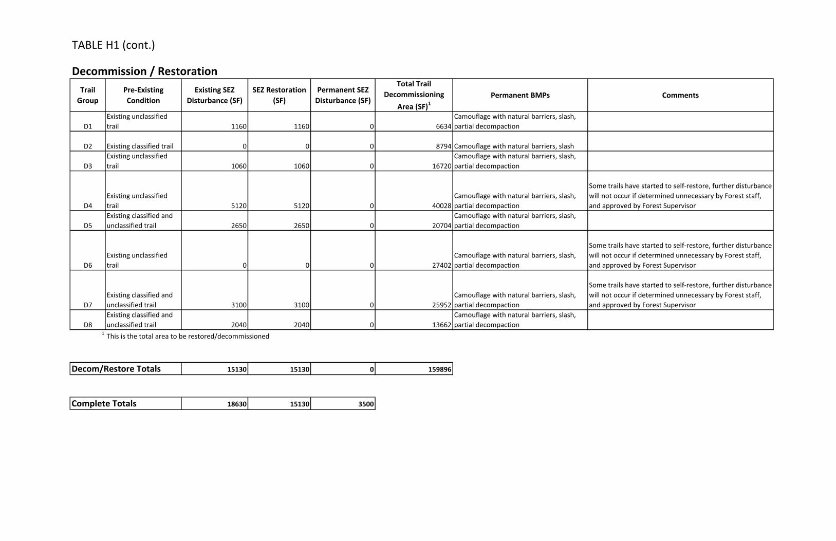
TABLE H1 (cont.)
Decommission / Restoration
Trail
Group
Pre-Existing
Condition
Existing SEZ
Disturbance (SF)
SEZ Restoration
(SF)
Permanent SEZ
Disturbance (SF)
Total Trail
Decommissioning
Area (SF)1
Permanent BMPs Comments
D1
Existing unclassified
trail 1160 1160 0 6634
Camouflage with natural barriers, slash,
partial decompaction
D2 Existing classified trail 0 0 0 8794 Camouflage with natural barriers, slash
D3
Existing unclassified
trail 1060 1060 0 16720
Camouflage with natural barriers, slash,
partial decompaction
D4
Existing unclassified
trail 5120 5120 0 40028
Camouflage with natural barriers, slash,
partial decompaction
Some trails have started to self-restore, further disturbance
will not occur if determined unnecessary by Forest staff,
and approved by Forest Supervisor
D5
Existing classified and
unclassified trail 2650 2650 0 20704
Camouflage with natural barriers, slash,
partial decompaction
D6
Existing unclassified
trail 0 0 0 27402
Camouflage with natural barriers, slash,
partial decompaction
Some trails have started to self-restore, further disturbance
will not occur if determined unnecessary by Forest staff,
and approved by Forest Supervisor
D7
Existing classified and
unclassified trail 3100 3100 0 25952
Camouflage with natural barriers, slash,
partial decompaction
Some trails have started to self-restore, further disturbance
will not occur if determined unnecessary by Forest staff,
and approved by Forest Supervisor
D8
Existing classified and
unclassified trail 2040 2040 0 13662
Camouflage with natural barriers, slash,
partial decompaction1
Decom/Restore Totals 15130 15130 0 159896
Complete Totals 18630 15130 3500
This is the total area to be restored/decommissioned