Embed Size (px)
Citation preview
Storm WaterPollution Prevention Plan (SWPPP)
Pacific Gas & Electric CompanyDiablo Canyon Power Plant (DCPP)
June 2007
Pacific Gas & Electric Company
Rev. 1
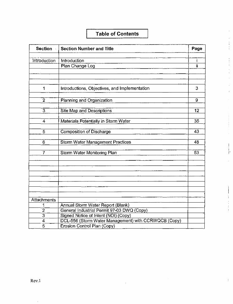
Table of Contents I
Section Section Number and Title Page
Introduction Introduction iPlan Change Log ii
1 Introductions, Objectives, and Implementation 3
2 Planning and Organization 9
3 Site Map and Descriptions 12
4 Materials Potentially in Storm Water 35
5 Composition of Discharge 43
6 Storm Water Management Practices 48
7 Storm Water Monitoring Plan 53
Attachments1 Annual Storm Water Report (Blank)2 General Industrial Permit 97-03 DWQ (Copy)3 Signed Notice of Intent (NOI) (Copy)4 DCL-556 (Storm Water Management) with CCRWQCB (Copy)5 Erosion Control Plan (Copy) _
Rev. 1
INTRODUCTION
Storm Water Pollution Prevention Plan(SWPPP PLAN)
June 2007
Pacific Gas and Electric Company (PG&E), has prepared this Storm Water PollutionPrevention Plan (SWPPP) for Diablo Canyon Power Plant (DCPP) in order to minimize theaffects of storm water runoff to the environment.
This plan has been prepared pursuant to State Water Resources Control Board WaterQuality Order No. 97-03-DWQ as part of the National Pollution Discharge EliminationSystem (NPDES) General Permit No. CA0003751.. This plan will be reviewed andevaluated at least once every year (in accordance with regulatory requirements).
Rev. 1
Storm Water Pollution Prevention Plan
CHANGE LOG
Diablo Canyon Power Plant
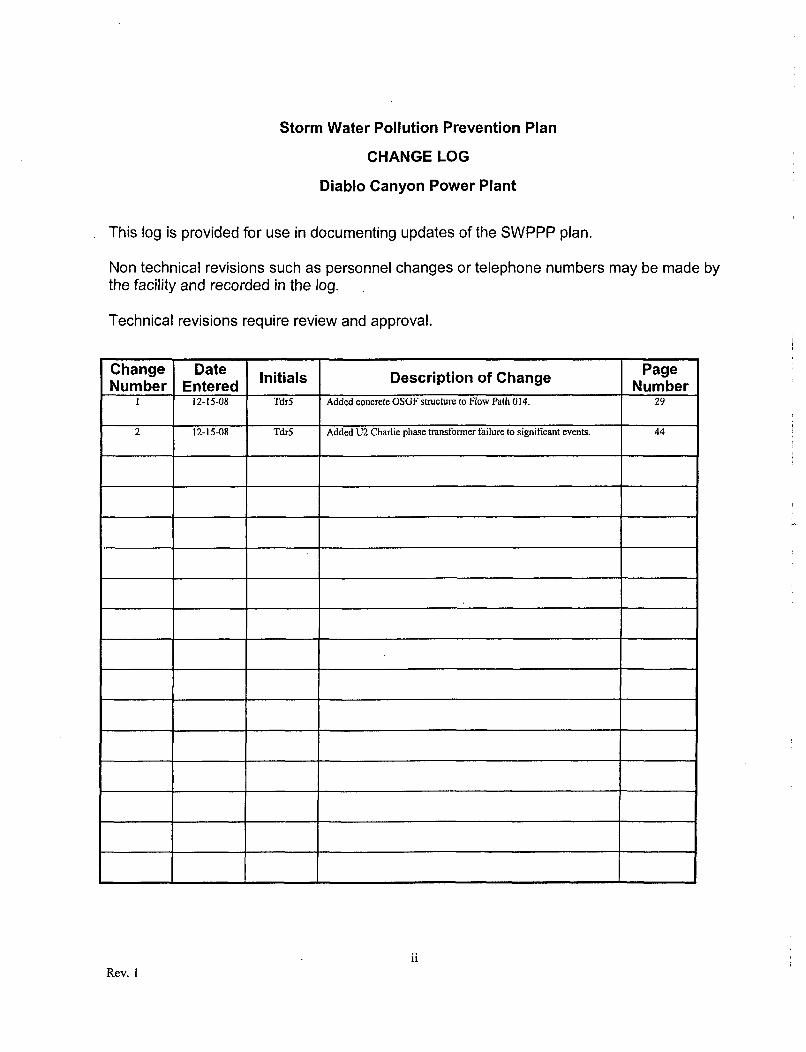
This log is provided for use in documenting updates of the SWPPP plan.
Non technical revisions such as personnel changes or telephone numbers may be made bythe facility and recorded in the log.
Technical revisions require review and approval.
Change Date Initials Description of Change PageNumber Entered Number
1 12-15-08 Tdr5 Added concrete OSGF structure to Flow Path 014. 29
2 12-15-08 Tdr5 Added U2 Charlie phase transformer failure to significant events. 44
iiRev. I
STORM WATER POLLUTION PREVENTION PLAN
Section 1
Overview, Objectives, and Implementation
3
Rev. I
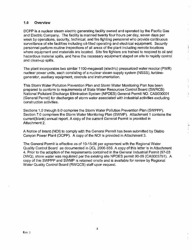
1.0 Overview
DCPP is a nuclear steam electric generating facility owned and operated by the Pacific Gasand Electric Company. The facility is manned twenty four hours per day, seven days perweek by operations, security, technical, and fire fighting personnel who provide continuoussurveillance of site facilities including oil-filled operating and electrical equipment. Securitypersonnel perform routine inspections of all areas of the plant including remote locationswhere equipment and materials are located. Site fire fighters are trained to respond to oil andhazardous material spills, and have the necessary equipment staged on site to rapidly controland clean-up spills.
The plant incorporates two similar 1100-megawatt (electric) pressurized water reactor (PWR)nuclear power units, each consisting of a nuclear steam supply system (NSSS), turbine-generator, auxiliary equipment, controls and instrumentation.
This Storm Water Pollution Prevention Plan and Storm Water Monitoring Plan has beenprepared to conform to requirements of State Water Resources Control Board (SWRCB)National Pollutant Discharge Elimination System (NPDES) General Permit NO. CAS000001(General Permit) for discharges of storm water associated with industrial activities excludingconstruction activities.
Sections 1.0 through 6.0 comprise the Storm Water Pollution Prevention Plan (SWPPP).Section 7.0 comprises the Storm Water Monitoring Plan (SWMP). Attachment 1 contains thecurrent(blank) annual report. A copy of the current General Permit is provided inAttachment 2.
A Notice of Intent (NOI) to comply with the General Permit has been submitted by DiabloCanyon Power Plant (DCPP). A copy of the NOI is provided in Attachment 3.
The General Permit is effective as of 10-15-06 per agreement with the Regional WaterQuality Control Board as documented in DCL 2006-556. A copy of this letter is in Attachment4. Prior to the adoption of the requirements contained in the General Industrial Permit (97-03DWQ), storm water was regulated per the existing site NPDES permit 90-09 (CA0003751). Acopy of this SWPPP and SWMP is retained onsite and is available for review by RegionalWater Quality Control Board (RWQCB) staff upon request.
4Rev. I
1.1 OBJECTIVES
The SWPPP for DCPP has two major objectives:
> Identify the potential sources of pollutants that may affect the quality of industrial stormwater discharges and authorized non-storm water discharges; and
> Identify and implement site-specific Best Management Practices (BMPs) to reduce orprevent pollutants in industrial storm water discharges and authorized non-storm waterdischarges.
5Rev. 1
1.2 IMPLEMENTATION
The Diablo Canyon Power Plant (DCPP) is describes as follows:
Type of Facility
Nuclear Powered Electricity Generation Facility
Location of Facility
Diablo Canyon Power Plant9 Miles NW of Avila BeachP.O. Box 56Avila Beach, CA 93424
DCPP is located on a remote ocean cove approximately nine miles (12 kilometers) westnorthwest of Avila Beach, San Luis Obispo County, California. The DCPP plant site consistsof approximately 585 acres that includes a 500 KV and 230 KV switchyards for electricaltransmission. The exact location is as follows:
Latitude: 35012'44"NLongitude: 120 051'14"WTownship: T31SRange: R10ESection: SW 1/4 Section 24Principal Meridian: Mt. Diablo Base Meridian
Average annual rainfall (12 year historical) is 24.35 inches.
The plant site does not have a history of flooding.
Storm water effluent from the site is intermittent and occurs at site storm water dischargelocations (Figure 1). There are no flows of industrial storm water on to the facility from offsitesources.
Owner / Operator
Pacific Gas and Electric Company (PG&E)P. 0. Box 770000San Francisco, CA 94177
Designated person responsible for the SWPPP at this facility
Trevor D. RebelEnvironmental SpecialistTelephone: (805) 545-3607
Rev. 1
1.3 Applicability
The General Permit applies to all facilities in California that have submitted an NOI forcoverage under the General Permit to discharge storm water associated with industrialactivities.
Within the context of the SWPPP, "authorized" non-storm water discharges are thoseauthorized within bounds of the General Permit. All other point source discharges to waters ofthe state of California, that occur at DCPP, are covered under a separate NPDES Permit(NPDES CA0003751, 90-09).
This permit is not part of the objectives identified in Appendix B (Environmental ProtectionPlan) of the Diablo Canyons' Nuclear Regulatory Commission (NRC) Operating license.
The General Permit and SWPPP do not cover construction activities greater involving greaterthan 1 acre of land. Any construction activity greater than 1 acre shall obtain a ConstructionSWPPP as described in storm water permits for construction activities 99-08-DWQ.
1.4 Compliance
Compliance with the General Permit will be in accordance with the storm water monitoringplan contained in section 7.0 of this document.
1.5 Best Management Practice (BMP)
Diablo Canyons' SWPPP emphasizes BMPs that are appropriate for industrial activities atDCPP. The SWPPP identifies and assesses potential sources of pollutants at DCPP anddescribes the appropriate BMPs necessary to reduce or prevent the discharge of pollutants.DCPP's SWPPP and monitoring program requirements include various inspections, reviews,and observations that recognize, encourage, and mandate an iterative self-evaluationprocess to consistently comply with the General Permit.
BMP is completely described in section 6.0 of this document.
1.6 Training
Training is required for those personnel responsible for:
> Implementing activities identified in the SWPPP> Conducting Inspections, Sampling, or visual observations> Managing storm water
7Rev. 1
1.7 Revision
The SWPPP will be reviewed and revised during the life of the operating facility inaccordance with the General permit. At a minimum, revision will occur:
> When requested by the SRWQCB (State Regional Water Quality Control Board)> Prior to any changes at DCPP that may significantly increase pollutants, changes in
industrial activities, or introduce a new pollutant source at the facility.> As necessary to ensure compliance with the requirements of the General Permit.> As part of the Annual Compliance Review.
8Rev. I
STORM WATER POLLUTION PREVENTION PLAN
Section 2
Planning and Organization
Rev. I
2.0 Storm Water Pollution Prevention Team
The organizations and/or persons listed below serve as members of the storm water pollutionprevention team. Team responsibilities include:
Development of the SWPPP• Revising the SWPPP> Monitoring and Inspection> Submission of the Annual Report
Specific responsibilities are described as follows:
Environmental Operations (Trevor Rebel)
> Responsible for coordination and maintaining the SWPPP as a living document, preparingand submitting the annual report by July 1st of each year, and coordinating/performingsampling and inspection..
Chemistry Section
> Assisting in the collection and analysis of storm water samples and inspections.
Civil Engineering
> Providing engineering evaluations and designs (when appropriate) to support theSWPPP.
Facilities Maintenance
> Performing physical work and maintenance of storm water systems within the boundariesof physical work allowed by building services.
Fire Department
> Provide emergency response for any spill or accident on site.
Hazardous Waste Group
> Inspection and maintenance of hazardous waste on site. Additionally, hazardous wastegroup perform decontamination and clean up activities following a hazardousmaterials/waste incident in accordance with plant procedures CP M-9D.
Operations
> Operators perform routine surveillance and inspection of facility operating equipment.
10Rev. 1
2.1 Other Plans and Procedures
The following existing facility plans and procedures have been prepared by DCPP pursuantto environmental regulatory requirements applicable to DCPP. Relevant and appropriateelements of these plans and systems are cited throughout the SWPPP.
Best manaQement Practices Plan (BMP)
> BMP to limit affects of storm water and the NPDES permit
Erosion Control Plan for Diablo Canyon Power Plant (DCM No. CA-72.doc)
> Preservation of natural landscape and prevent loss of soil and sediment from erosion.
Hazardous Materials Incident Post Emergency Clean-Up Procedure (CP M-9D)
> Site emergency response procedure for hazardous material incidents. This procedureIncludes reportable quantities to regulatory agencies.
Spill Prevention Control and Countermeasure Plan (SPCC)
> Pursuant to 40 CFR, Part 112 and 761
Volume 2 of Hazardous Materials Business Plan
> Describes quantities and locations of hazardous materials
11Rev. 1
STORM WATER POLLUTION PREVENTION PLAN
Section 3
Site Map and Descriptions
12Rev. 1
3.0 Site Map
A map of the facility is provided in Figure 1.
The following information is included on the site map:
> The facility boundaries; the outline of storm water drainage areas within the facilityboundaries; portions of the drainage area impacted by run-on from surrounding areas;and direction of flow of each drainage area. The map also identifies onsite and nearbywater bodies.
> The location of the storm water collection and conveyance systems, associated points ofdischarge, and direction of flow. Structural control measures such as retention basins andcatch basins that affect storm water discharges are included.
> An outline of impervious areas of the facility, including paved areas, buildings, covered
storage areas, or other roofed structures.
> Areas where Significant Materials may be exposed to precipitation.
> Areas of industrial activities, including the locations of storage areas and storage tanks,shipping and receiving areas, fueling areas, vehicle and equipment storage/maintenanceareas, material handling areas, dust or particulate generating areas, and other areas ofindustrial activity which are potential pollutant sources.
Non Industrial Flows
As described in section 1.2 there are no flows of industrial water onto the facility from offsitesources. Surrounding lands within watersheds are used for agriculture. Portions of thedrainage area are impacted by run-on from surrounding areas and the direction of flow fromeach drainage area, are depicted in Figure 1 via the topographic contours. With the exceptionof intermittent drainages that flow in response to precipitation, the only on site natural waterbodies are the Pacific Ocean and Diablo Creek.
Impervious Surfaces
Approximately 25 percent of the site is impervious due to pavement, structures, or otherimprovements.
13Rev. 1
Non Relevant Information
Several requirements for site maps within the General Permit are not relevant to DCPP asdescribed below:
> There are no disposal areas at DCPP.
> Waste Treatment is performed inside structures and is not exposed to storm water.
> There have been no past significant spills at DCPP that could affect the quality of stormwater.
> Most Industrial activities are performed indoors and are not exposed to storm water.Outdoor activity exposed to storm water is indicated on the site map.
14Rev. 1
3.1 Description of Storm Water Flow Paths and Industrial Activities
The following numerical points do not constitute a discharge point associated with stormwater but, are part of the site general NPDES permit 90-09.
> 001 Discharges associated with Once Through Cooling (OTC) water
> 002 Discharge associated with Intake Screen Wash System
> 016 Biology Lab Seawater Pump Valve Drain
> 017 Sea Water Reverse Osmosis System Blow down Drain
The following numerical discharge points appear on the Site Storm Water Drainage Map(Figure 1), however, do not, constitute a discharge associated with the General IndustrialStorm Water Permit.
> 019 No longer a discharge point (combined with 004; reference A0603408)
> 022 Biology Lab/ Reverse Osmosis Supply Lines Drain
> 024 Access Road drains not associated with the industrial site
> 025 Access Road drains not associated with the industrial site.
> 026 Circulating Water Pump (CWP) backflow to Intake Cove
> 027 Screen Wash refuse sump overflow to Intake Cove
The following pages in this section provide a narrative description of each storm water flowpath including:
> Descriptor of Path> Activity in Path (Industrial, Materials Storage, Dust and Particulates)> Significant Materials> Assessment for Polluting Storm Water
15Rev. I
Flow Path Boat: Marine Refueling Facility Runoff
Storm water generated near and around the marine refueling facility.
Activity in Path:
Industrial (Fueling), Materials Storage
Significant Materials:
Gasoline and Diesel.
Assessment for Polluting Storm Water:
The potential of pollutants reaching storm water for this path is low. Fuel is contained indouble wall fuel tanks which are provided with secondary containment.
Marine refueling is procedural zed and conducted with a minimum of two people inattendance.
A spill kit is in place at the marine r'efueling facility.
16Rev. 1
Flow Path 003: Yard Storm Drain
Storm water runoff from areas surrounding the seawater intake structure building travel throughthe 003 culvert before combining with seawater discharge from the intake screen wash system,and refuse sump seawater before discharge to the Pacific Ocean at the 003 discharge.
Activity in Path:
Industrial (Machine Shop, Outdoor Motors), Materials Storage
Significant Materials:
Activities and materials in this path include indoor machining equipment, lubricating oils,greases, solvents associated with a typical machine shop.
Assessment for Polluting Storm Water:
The potential of pollutants reaching storm water for this path is very low. All chemicals arestored indoors in cabinets and fire lockers as appropriate.
Permanent plant equipment exposed to storm water includes eight screen wash motors andthe lubricating oil contained within. In the event of catastrophic failure of one of these motors,oil could be released to NPDES pathway 003 which includes the component of storm waterdescribed above.
17Rev. I
Flow Path 004: Yard Storm Drains to Retention Basin
Sea water reverse osmosis high level drain and storm water, share a discharge to a retentionbasin behind the biological lab. Storm water is received in the retention basin from the followingsources prior to flowing through a riser pipe to discharge 004 at the intake cove:
>' Southeast side of the Unit 2 Turbine Building,> Administration Building,> Security Building,> Training and Maintenance Shop Buildings,> Parking lots 4 and 5,> Meteorological tower area,> A small area to the west side of the west plant access road,> Hazardous Waste Storage Unit,> Firewater storage tank,> Truck bay, and> Firewater pump building.
Activity in Path:
Industrial (Steam Electric Generation), Materials Storage
Significant Materials
U2 Transformer yard:
The U2 transformer yard has a significant amount of transformer oil contained in operating andstandby transformers. The site SPCC plan contains specific requirements for oil containingequipment.
Maintenance Shop Building:
The Maintenance Shop Building contains a chemistry laboratory. Sink drains from the laboratorycarry non-hazardous chemical reagents and wastewater to a transportable above-groundcarboy.
Central Hazardous Waste Storage Facility:
The Site Hazardous Waste Storage Unit is a completely enclosed structure. The floor is bermedand sloped to a self-contained sump to prevent the escape of hazardous waste. Each of threestorage tanks is provided with secondary containment. The loading area is sloped and valved tocontain any releases during transfer.
18Rev. I
(Flow path 004 Continued)
Assessment for Polluting Storm Water
The majority of all pollutant sources in flow path 004 are contained inside buildings. Thehazardous waste facility contains a system of berms and sumps for the containment of anyspilled material. Transformer yard spillage of oils is mitigated with a 17,000 gallon passiveOily Water Separator (OWS).
Additionally, all storm water is collected in the 004 retention basin. The settling basin must fillprior to flowing through a riser pipe to the Intake Cove.
19Rev. I
Flow Path 005: Yard Storm Drains
Storm water is collected in a drainage system and routed immediately north of Patton Cove fordischarge.'
> Plant Yard on the Unit 2 side of the Radwaste Buildings,) West side of the Turbine Building,> Main Warehouse,> Hazardous Materials Warehouse,> Construction Offices,> Parking lots 2, 3, 6, 7, and 8,> Cold Machine Shop,> Seawater Reverse Osmosis Facility,> Biology Laboratory (not in service)> Fabrication Shop.
Activity in Path:
Industrial (Machine Shop), Materials Storage
Significant Materials:
Significant materials that are stored in buildings and may be used or transported within theplant yard area draining to Discharge 005 could include boric acid, sulfuric acid, sodium bi-sulfite, sodium hydroxide, ethanolamine, ammonium hydroxide, hydrazine, carbohydrazide,diesel fuel oil, lubricating oils, transformer oils, laboratory chemicals, and cleaning solvents.
Assessment for Polluting Storm Water:
The majority of potential pollutants in this flow path are stored indoors and do not pose athreat do storm water.
Some potential exists, if an incident were to occur during chemical offload in front of the westside turbine building buttress. Chemical offload evolutions are fully procedural zed, briefedand monitored continuously during offload evolutions to rapidly respond to any spills orleakage.
20Rev. 1
Flow Path 006: Yard Storm Drain
Storm water drains to discharge 006 from the following areas:
> Pacific Ocean side of the ridge to the southeast of the plant> Warehouse B (currently converting to an office area)> Shooting Range> Outdoor Abrasive Blast Facility> Vehicle Fueling> Parking Lot #1
Activities in Path:
Industrial (Shooting Range), Materials Storage, Dust and Particulates (Sandblast)
Significant Materials
The shooting range has the potential for lead (Pb) contamination and debris from shooting rangeactivities.
The Outdoor Abrasive Blast Facility materials.
Assessment for Polluting Storm Water
The potential for pollutants reaching storm water for this path is high if proper BMP is notfollowed.
The shooting range has the potential for pollution from lead (Pb) and debris from shootingrange activities. Drainage from the shooting range is directed to an engineered catch basindesigned to separate and contain solids from range runoff.
The outdoor abrasive blast facility could add significant amounts of sand blast media andpaint materials if proper BMP is not followed. This area is cleaned as necessary to minimizethe potential of solids being released to the waters of the State. Removed material isproperly analyzed and disposed.
Vehicle fueling has the potential for adding petroleum products to storm water. An above-ground vaulted, double wall diesel fuel oil and gasoline storage tanks for vehicle refueling arelocated in the area draining to this discharge. The double wall tanks are contained withinsecondary containment berms. The refueling area has a concrete pad that is sloped anddiverts potential fuel spills to an engineered retention basin.
Fleet vehicle refueling trucks are parked on an asphalt pad downstream of the fuel storagetanks. The asphalt pad is designed to direct and leakage or spills to the retention basin.
21Rev. 1
Flow Path 007: Storm Water Runoff
Storm water from watershed South and East of the facility. There are no industrial activitiespresent in this path. Water discharges to an inaccessible rip-rap field west of the facility.
Activities in Path
No industrial activity in this flow path.
Significant Materials:
None
Assessment for Polluting Storm Water
The potential for polluting storm water in this path is very low. There is no industrial activity in thispath.
22Rev. 1
Flow Path 008: Yard Storm Drains
Storm water drains to discharge 008 from the following areas:
;• Northwest side of the Turbine Building,> Technical Maintenance Building, and> The watershed on the north side of Diablo Creek to the northwest of DCPP.
Activity in Path:
Industrial (Power Production), Materials Storage
Significant Materials
The Calibration Lab within the Technical Maintenance Shop building maintains some hazardousmaterials under proper storage.
A solution of sodium bi-sulfite is stored in a bulk chemical storage tank outside the west buttressarea of the Unit I Turbine Building. The tank is provided with secondary containment.
Other hazardous materials that are stored in buildings and may be used or transported within theplant yard area drained by discharge 008 could include sulfuric acid, sodium hydroxide, sodiumhypochlorite, ammonium hydroxide, hydrazine, carbohydrazide, potassium molybdate, diesel fueloil, lubricating oils, and transformer oils.
Assessment for Polluting Storm Water:
The potential of pollutants reaching storm water in this path is low. The majority of all activity andstorage is indoors. Chemical offload evolutions are fully procedural zed, briefed and monitoredcontinuously during offload evolutions to rapidly respond to any spills or leakage.
23Rev. 1
Flow Path 009: Yard Storm Drains
Storm water from the north and northeast side of the Unit 1 Auxiliary, Containment, FuelHandling, and Turbine buildings drains to the north side of the yard to discharge 009.
Activity in Path:
Industrial (Power Production), Materials Storage
Significant Materials:
Hazardous materials that are stored in buildings and may be used or transported within the plantyard area drained by discharge 009 could include boric acid, hydrazine, potassium molybdate,diesel fuel oil, and transformer oil. A 17,000 gallon sump with a passive oil separation system isprovided for containment of an oil spill involving Unit 1 transformer yard. Management of oilspills is described in the SPCC plan.
Assessment for Polluting Storm Water:
The potential for pollutants reaching storm water for this path is low. A 17,000 gallon capacitypassive OWS for the U1 transformer yard is designed to capture oils in the event of atransformer leakage or failure.
24Rev. 1
Flow Path 010: Yard Storm Drain
Runoff from the hillside between DCPP and the Raw Water Reservoirs drains into a concreteculvert and is routed to the north along the hillside for discharge.
Activity in Path:
Industrial (make-up water treatment)
Significant Materials:
Water treatment chemicals
Assessment for Polluting Storm Water:
The potential for polluting storm water in path 010 is very low. All chemicals are storedindoors or otherwise covered at the water treatment facility.
In the event of a reservoir leak or piping system failure, potable water could be released outpath 010. Discharge path 010 flows to a chaparral hillside.
25Rev. 1
Flow Path 011: Yard Storm Drain
Runoff from Diablo Creek Road, the north side of the 230kV and 500 kV switch yards.
Activity in Path:
Industrial (Electrical Transmission)
Significant Materials:
The only significant material stored in this flow path are oil containing transformers.
Assessment for Polluting Storm Water:
The potential for polluting storm water in path 011 is very low. Each of the 230 kV and 500 kVswitchyards are equipped with retention basins to capture any failure of oil containing equipment.
26Rev. 1
Flow Path 012: Yard Storm Drain
Runoff from the area between the 230 KV Switchyard and the 500 KV Switchyard drains to avertical shaft leading to the underground culvert containing Diablo Creek water as it passesunder the switchyards.
Activity in Path:
Industrial (Electrical Transmission)
Significant Materials:
The only significant material stored in this flow path are oil containing transformers.
Assessment for Polluting Storm Water:
The potential for polluting storm water in path 011 is very low. Each of the 230 kV and 500 kVswitchyards are equipped with retention basins to capture any failure of oil containing equipment.
A sediment retention basin has been recently constructed (August 2006) in Tri-Bar flats. Thebasin has been designed to capture sediment laden storm water from adjacent hillsides and de-silt the water prior to discharge at 012.
27Rev. 1
Flow Path 013: Yard Storm Drains
Storm water drains to discharge 013 from the following areas:
) Raw Water Reservoirs,> Makeup Water Treatment area,> 230 KV Switchyard, and> The watershed on the hillside under the 500 KV power lines leading east from the plant.
Activity in Path:
Industrial (Electrical Transmission, Makeup Water Treatment)
Significant Materials:
Significant materials is this flow path include oil containing electrical transformers and makeupwater treatment chemicals.
Assessment for Polluting Storm Water:
The potential for polluting storm water in path 013 is very low. Each of the 230 kV and 500 kVswitchyards are equipped with retention basin to capture any failure of oil containingequipment.
Water treatment chemicals are indoors or covered with the exception of a sodiumhypochlorite tank for makeup water treatment. The hypochlorite tank has secondarycontainment.
28Rev. 1
Flow Path 014: Storm Water Runoff
Storm water runoff from lay-down areas and the hillside south and east of the 500 KV Switchyardis collected in a drainage ditch and routed to discharge 014.
Activity in Path:
Industrial (Electrical Transmission), Watershed, OSGF Storage (Concrete Storage Building)
Significant Materials:
Significant materials in this flow path include oil containing electrical transformers.
Assessment for Polluting Storm Water:
The potential for polluting storm water in path 014 is very low. The 500 kV switchyard isequipped with retention basin to capture any failure of oil containing equipment.
The majority of storm water in this flow path is from watersheds with no industrial activity.
29Rev. 1
Flow Path 015: Yard Storm Drains
Storm water runoff from the area around the temporary auto facilities and adjacent roadway iscollected in a drainage ditch and routed to discharge 015.
Activity in Path:
Industrial (Fleet vehicle maintenance), Materials Storage
Significant Materials:
Significant materials that are stored in buildings or structures and may be used or transportedwithin the plant yard area that drains to Discharge 015 could include ethylene glycol, acetylene,lubricating oils, diesel fuel, and solvents. All storage is protected from storm water. The majorityof maintenance is performed inside the garage (covered).
Assessment for Polluting Storm Water:
The potential for polluting storm water in this flow path is high if proper maintenance andmanagement practices are not performed.
30Rev. I
Flow Path 018: Yard Storm Drains
Storm water runoff from the east side of the Intake Structure building.
Activity in Path:
Industrial (Machine Shop), Materials Storage
Significant Materials:
Storm water runoff from the area east of and immediately adjacent to the Intake Structure andthe Intake Structure platform drain into a sump with a valve controlled drain. When the valve ismanually opened the sump drains to discharge. The following three bulk chemical storage tanksare located in the platform drainage area.
Two sodium hypochlorite tanks are located next to the Intake Structure Security Building. Bothtanks are provided with secondary containment and tertiary containment berms.
A sodium bromide tank is located next to the sodium hypochlorite tanks. The tank is providedwith secondary containment and a tertiary containment berm.
Chemical delivery piping for the tanks listed above is double walled to contain and minimize thepotential of releases from primary piping failure. The area around the tanks is paved and gradedto contain the volume of the tanks in the event of a major rupture of a pipe or tank, or from a spillduring filling operations.
Assessment for Polluting Storm Water:
The potential for polluting storm water in this path is low. The valve controlling flow to point 018is normally shut. The valve is opened after verifying contamination is not present in pathway.
31Rev. 1
Flow Path 020: Intake Deck Storm Drains
Storm water collected directly in front of screen housing drains to circulating water pump fore-bays through open grating.
Activity in Path:
Industrial (Oil Containing Equipment)
Significant Materials:
Oil containing motors from fourteen separate screen wash system motors. Oil containing motorsand hydraulics from the Intake gantry crane.
Assessment for Polluting Storm Water:
The potential for polluting storm water in this path is low. All oil filled motors and machinery isfrequently inspected and serviced to prevent leakage and/or failure of operating equipment.
32Rev. I
Flow Path 021: Yard Storm Drain
Screen wash system over spray drains and storm water from the east of the traveling screendeck discharge to 021.
Activity in Path:
Industrial (Oil Containing Equipment)
Significant Materials:
Oil containing motors from fourteen separate screen wash system motors. Oil containing motorsand hydraulics from the Intake gantry crane.
Assessment for Polluting Storm Water:
The potential for polluting storm water in this path is low. All oil filled motors and machinery isfrequently inspected and serviced to prevent leakage and/or failure of operating equipment.
33Rev. 1
Flow Path 023: Yard Storm Drain
Storm water generated on the North and East sides of the Intake Structure building drain to theIntake cove at discharge point 023.
Activity in Path:
Industrial (Storage and Lay-down)
Significant Materials:
This area may contain lay down materials and screen housings after the housings have beenremoved from the Intake cover.
Assessment for Polluting Storm Water:
The potential for polluting storm water in this path is very low.
34Rev. 1
STORM WATER POLLUTION PREVENTION PLAN
Section 4
Materials Potentially In Storm Water
35Rev. 1
4.0 List of significant materials and storage locations, frequencies, and quantities
Volume 2 of the DCPP Hazardous Material Business Plan contains pertinent information forall significant materials stored at DCPP, including specific storage locations and quantities.
The vast majority of material on site are stored indoors and does not pose a threat to stormwater.
Project-significant materials may be used onsite at various times. All special projectsmaterials are reviewed prior to arriving on site and must comply with site maintenance andstorage procedures.
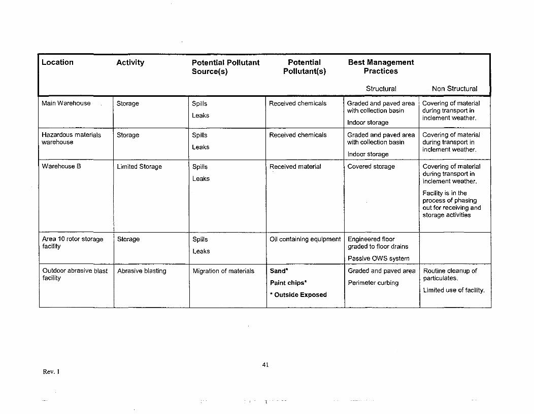
Table 1 on the following pages summarizes potential storm water pollutants and indicateswhich materials are exposed to storm water.
> Note: Materials exposed to storm water are bolded.
Table 2 contains typical chemical offload volumes and frequencies of delivery.
36Rev. I
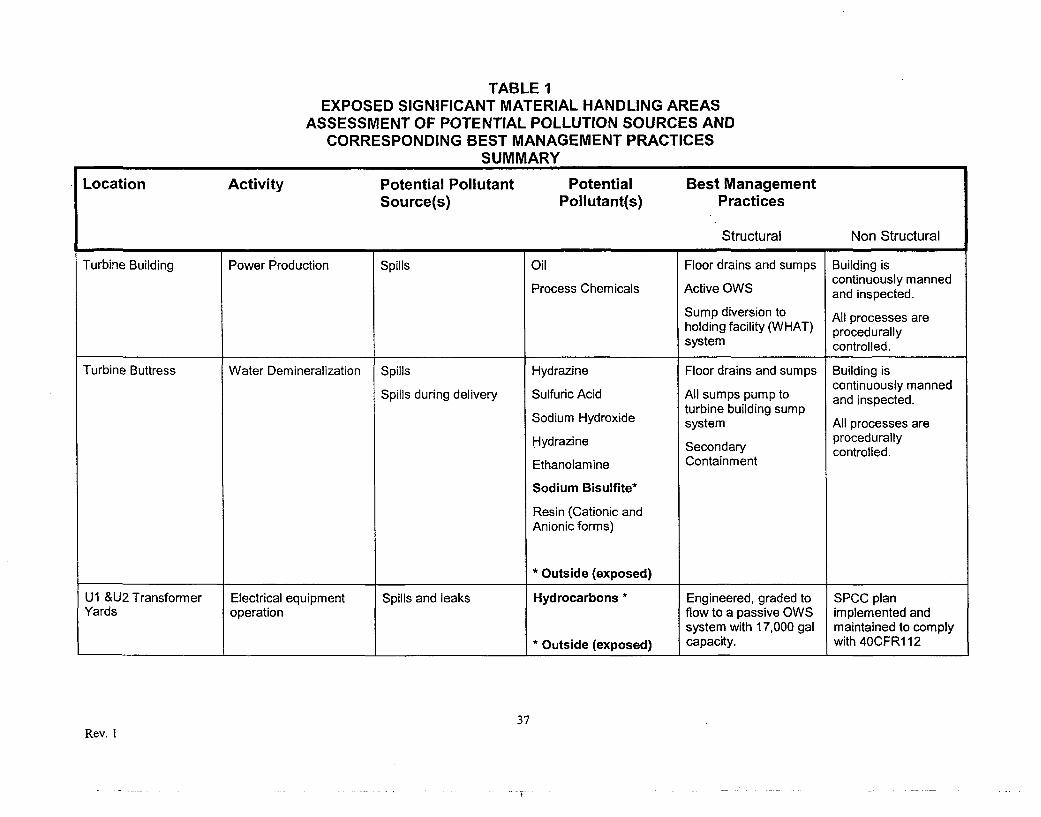
TABLE 1EXPOSED SIGNIFICANT MATERIAL HANDLING AREAS
ASSESSMENT OF POTENTIAL POLLUTION SOURCES ANDCORRESPONDING BEST MANAGEMENT PRACTICES
SUMMARY
Location Activity Potential Pollutant Potential Best ManagementSource(s) Pollutant(s) Practices
Structural Non Structural
Turbine Building Power Production Spills Oil Floor drains and sumps Building iscontinuously mannedProcess Chemicals Active OWS and inspected.
Sump diversion to All processes areholding facility (WHAT) procedurallysystem controlled.
Turbine Buttress Water Demineralization Spills Hydrazine Floor drains and sumps Building iscontinuously manned
Spills during delivery Sulfuric Acid All sumps pump to and inspected.
turbine building sumpSodium Hydroxide system All processes areprocedurallyHydrazine Secondary controlled.
Ethanolamine Containment
Sodium Bisulfite*
Resin (Cationic andAnionic forms)
* Outside (exposed)
U1 &U2 Transformer Electrical equipment Spills and leaks Hydrocarbons * Engineered, graded to SPCC planYards operation flow to a passive OWS implemented and
system with 17,000 gal maintained to comply* Outside (exposed) capacity. with 40CFR1 12
37Rev. I
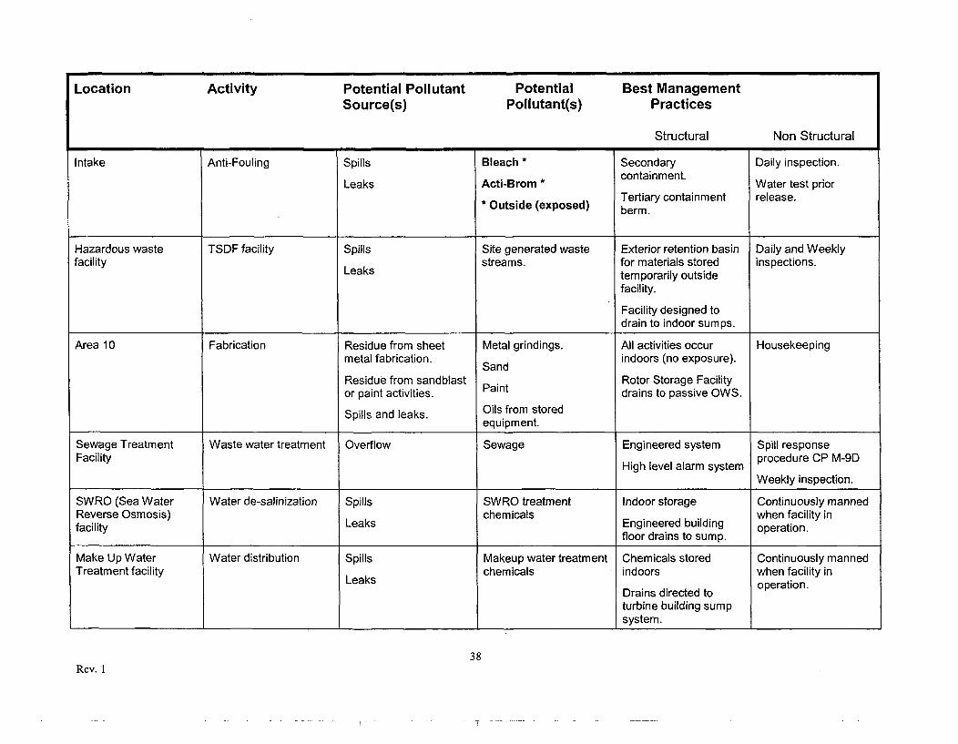
Location Activity Potential Pollutant Potential Best ManagementSource(s) Pollutant(s) Practices
Structural Non Structural
Intake Anti-Fouling Spills Bleach * Secondary Daily inspection.
Leaks Acti-Brom *containment. Water test priorTertiary containment release.
Outside (exposed) berm.
Hazardous waste TSDF facility Spills Site generated waste Exterior retention basin Daily and Weeklyfacility Leaks streams. for materials stored inspections.
temporarily outsidefacility.
Facility designed todrain to indoor sumps.
Area 10 Fabrication Residue from sheet Metal grindings. All activities occur Housekeepingmetal fabrication. Sand indoors (no exposure).
Residue from sandblast Rotor Storage Facilityor paint activities. Paint drains to passive OWS.
Spills and leaks. Oils from storedequipment.
Sewage Treatment Waste water treatment Overflow Sewage Engineered system Spill responseFacility High level alarm system procedure CP M-9D
Weekly inspection.
SWRO (Sea Water Water de-salinization Spills SWRO treatment Indoor storage Continuously mannedReverse Osmosis) chemicals when facility infacility Leaks Engineered building operation.
floor drains to sump. operation.
Make Up Water Water distribution Spills Makeup water treatment Chemicals stored Continuously mannedTreatment facility Leaks chemicals indoors when facility in
Drains directed to operation.
turbine building sumpsystem.
38Rev. 1
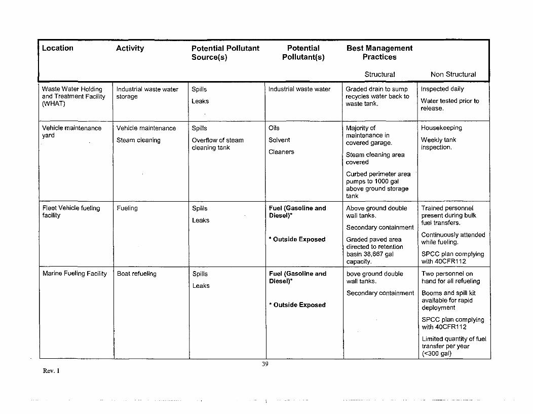
Location Activity Potential Pollutant Potential Best Management
Source(s) Pollutant(s) Practices
Structural Non Structural
Waste Water Holding Industrial waste water Spills Industrial waste water Graded drain to sump Inspected dailyand Treatment Facility storage recycles water back to(WHAT) Leaks waste tank. Water tested prior to
release.
Vehicle maintenance Vehicle maintenance Spills Oils Majority of Housekeepingyadmaintenance inWekytn
yard Steam cleaning Overflow of steam Solvent covered garage. Weekly tankcleaning tank inspection.
Cleaners Steam cleaning areacovered
Curbed perimeter areapumps to 1000 galabove ground storagetank
Fleet Vehicle fueling Fueling Spills Fuel (Gasoline and Above ground double Trained personnelfacility Leaks Diesel)* wall tanks. present during bulk
Secondary containment fuel transfers.Outside EpsContinuously attended*OtieExposed Graded paved area while fueling.
directed to retentionbasin 38,667 gal SPCC plan complyingcapacity. with 40CFR1 12
Marine Fueling Facility Boat refueling Spills Fuel (Gasoline and bove ground double Two personnel on
Leaks Diesel)* wall tanks. hand for all refueling
Secondary containment Booms and spill kitOutside Expavailable for rapid
eExposed deployment
SPCC plan complyingwith 40CFRI12
Limited quantity of fueltransfer per year(<300 gal)
39Rev. 1
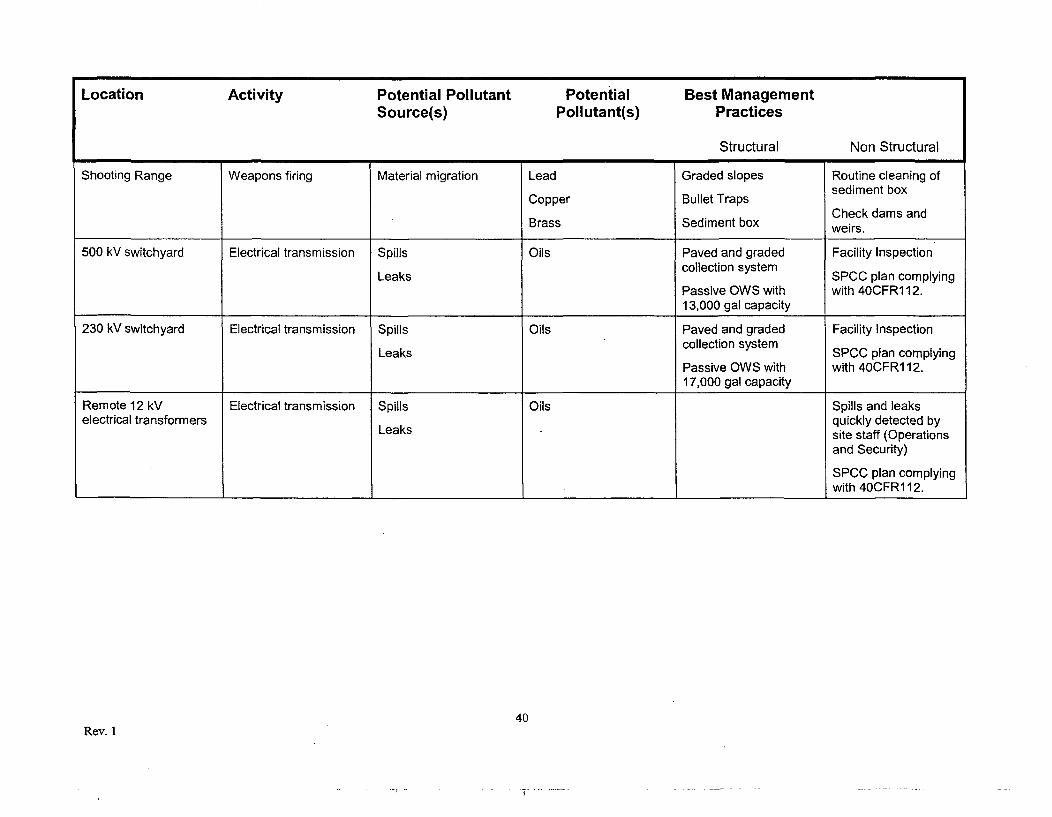
Location Activity Potential Pollutant Potential Best Management
Source(s) Pollutant(s) Practices
Structural Non Structural
Shooting Range Weapons firing Material migration Lead Graded slopes Routine cleaning of
Copper Bullet Traps sediment box
Check dams andBrass Sediment box weirs.
500 kV switchyard Electrical transmission Spills Oils Paved and graded Facility InspectionLeaks collection system SPCC plan complying
Passive OWS with with 40CFR1 12.13,000 gal capacity
230 kV switchyard Electrical transmission Spills Oils Paved and graded Facility InspectionLeaks collection system SPCC plan complying
Passive OWS with with 40CFR1 12.17,000 gal capacity
Remote 12 kV Electrical transmission Spills Oils Spills and leakselectrical transformers quickly detected by
Leaks site staff (Operationsand Security)
SPCC plan complyingwith 40CFR112.
40Rev. 1
Location Activity Potential Pollutant Potential Best Management
Source(s) Pollutant(s) Practices
Structural Non Structural
Main Warehouse Storage Spills Received chemicals Graded and paved area Covering of materialwith collection basin during transport in
Leaks inclement weather.Indoor storage
Hazardous materials Storage Spills Received chemicals Graded and paved area Covering of materialwarehouse with collection basin during transport in
Leaks inclement weather.Indoor storage
Warehouse B Limited Storage Spills Received material Covered storage Covering of materialduring transport in
Leaks inclement weather.
Facility is in theprocess of phasingout for receiving andstorage activities
Area 10 rotor storage Storage Spills Oil containing equipment Engineered floor
facility Leaks graded to floor drains
Passive OWS system
Outdoor abrasive blast Abrasive blasting Migration of materials Sand* Graded and paved area Routine cleanup offacility Paint chips* Perimeter curbing particulates.
* Outside Exposed Limited use of facility.
41Rev. I
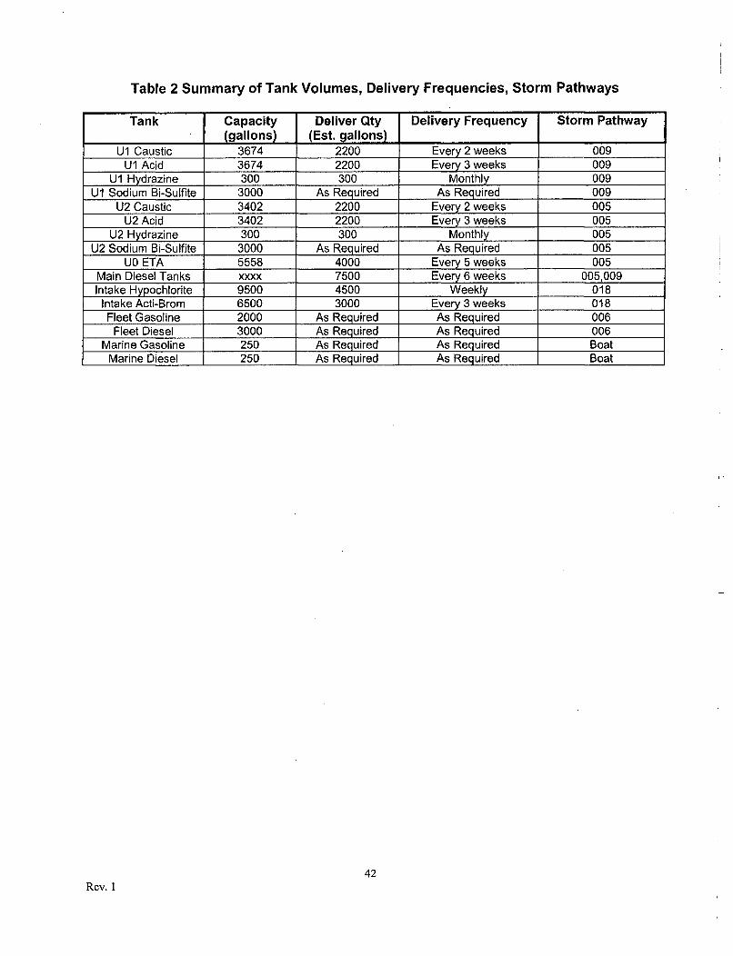
Table 2 Summary of Tank Volumes, Delivery Frequencies, Storm Pathways
Tank Capacity Deliver Qty Delivery Frequency Storm Pathway(gallons) (Est. gallons)
U1 Caustic 3674 2200 Every 2 weeks 009U1 Acid 3674 2200 Every 3 weeks 009
U1 Hydrazine 300 300 Monthly 009UI Sodium Bi-Sulfite 3000 As Required As Required 009
U2 Caustic 3402 2200 Every 2 weeks 005U2 Acid 3402 2200 Every 3 weeks 005
U2 Hydrazine 300 300 Monthly 005U2 Sodium Bi-Sulfite 3000 As Required As Required 005
UO ETA 5558 4000 Every 5 weeks 005Main Diesel Tanks xxxx 7500 Every 6 weeks 005,009Intake Hypochlorite 9500 4500 Weekly 018
Intake Acti-Brom 6500 3000 Every 3 weeks 018Fleet Gasoline 2000 As Required As Required 006
Fleet Diesel 3000 As Required As Required 006Marine Gasoline 250 As Required As Required Boat
Marine Diesel 250 As Required As Required Boat
42Rev. 1
STORM WATER POLLUTION PREVENTION PLAN
Section 5
Composition of Discharge
43Rev. I
5.0 Significant Spills and Leaks
The following describes the spill history for Diablo Canyon for materials entering storm waterpathways since April 17, 1994 which have exceeded reportable quantities as described in 40CFR 110, 117, and 302.
10/21/95 - Transformer Explosion
A transformer failure and explosion released up to 3400 gallons of Diala AX Transformer Oil.Oil flowed to the passive OWS. An unknown amount of oil reached Diablo Creek and thePacific Ocean. The spilled oil was cleaned up and/or dissipated.
8-17-08 - U2 Charlie Phase Transformer Failure
A transformer failure and resulting fire released Diala AX Transformer Oil. Most of the oil wasconsumed in the fire based on visual inspection of the Intake Cove and the OWS passivesump. Some biodegradable fire fighting foam reached Waters of the State. Central CoastRegional Water Quality Control Board Staff was notified. Documentation of event is containedin A0738071, A0738155, A0738257, A0738494, A0739125.
44Rev. 1
5.1 Non Storm Water Discharges
The following non-storm water discharges are permitted with the General Industrial Permitprovided the discharges meet the following criteria:
1. The discharges are in compliance with Regional Board requirements.
2. BMPs are specifically included in the SWPPP to reduce or prevent contact withsignificant materials.
3. Volume of non-storm water discharge is kept to a minimum.
4. Non-storm water discharges do not contain significant quantities of pollutants.
5. The monitoring program includes quarterly visual observations of each non-stormwater discharge and its sources to ensure implemented BMPs are being implemented andeffective.
6. The non-storm water discharges are reported and described annually as part of theannual report.
The following non-storm water discharges are authorized, as described in 97-03 DWQ,
provided they meet discharge meets the requirements listed above:
Fire hydrant flushing
Potable water sources
Drinking fountain water
Atmospheric condensates
Irrigation Drainage
Landscape watering
Springs
Ground water
Building footing and drainage
Sea water infiltration where the sea waters are discharged back to the sea.
Fire Fighting activities
45Rev. I
5.2 Identified and Authorized Non-Storm Water Discharges
The following non-storm sources have been identified which have the potential to reach theplant storm water drain system:
Periodic deluge system and Fire Hydrant Flushing
Landscape watering at administration and training buildings
SWRO facility (Area 10) seawater leak off
Plant air compressor condensates
Potable water system leakage
46Rev. 1
5.3 Soil Erosion
Soil erosion on site is primarily due to the natural erosion processes. Engineered swales,debris traps, silt basins are used throughout the site to aid in mitigating the transport of siltand debris due to storm water runoff.
Diablo Canyon has an Erosion Control Plan (DCM CA-72) describing controls and practicesto minimize the affect of soil erosion on storm water quality.
There are no known erosion sites as the result of authorized non-storm water discharge. Allauthorized storm water discharges flow to engineered swales and drainages.
When areas of soil erosion or storm water conveyance system damage are identified, theproblem is documented in the facility corrective action program for correction.
A copy of the Diablo Canyon Erosion Control Plan is in Attachment 5 of this document.
47Rev. I
STORM WATER POLLUTION PREVENTION PLAN
Section 6
Storm Water Management Practices
48Rev. I
6.0 Storm Water Management Practices
The Diablo Canyon industrial site has a comprehensive set of controls in place to minimizestorm water contact with significant materials and minimize pollutants in storm water.Practices are described by category:
6.1 Structural BMP
Engineered Roads, Swales, Culverts
All storm water flows through a series of engineered ditches, swales, and culverts todischarge,
Passive Oil Water Separation
Oily water separators are used in the following locations:
> U1 Transformer Yard (17,000 gal capacity)> U2 Transformer Yard (17,000 gal capacity)> Area 10 Rotor Storage Building
Switchyard Retention Basins
Both the 500 kV and 230 KV yards are equipped with retention basins as part of the SPCCplan to prevent the release of transformer oils to discharge pathways.
Secondary Containment
All outdoor chemical storage tanks are equipped with secondary containment structures.
Tertiary containment exists for the following:
> Vehicle Fueling Station> Marine Fueling Station> Bio-Fouling control chemical tanks (Intake Area)
Debris Trap
The Diablo Canyon Shooting range is equipped with an engineered sediment trap.
Vehicle Maintenance Shop
The majority of vehicle maintenance occurs in a covered garage bay system.
A non-hazardous receiving water tank is in place for equipment steam cleaning.
Covered Materials Receiving Area
The materials receiving dock for the main warehouse is covered and protected from rain fall.
49Rev. 1
Settling Basins
A retention basin is in place for discharge path 004. Water is allowed to calm and settlebefore flowing through a riser pipe to the Diablo Intake Cove.
A retention basin is installed in the Tri-Bar flats area. Water is allowed to accumulate andcalm before flowing through a riser pipe to the 012 discharge pathway and Diablo Creek.
A weir has been installed in the 005 flow path to aid in dropping out sediment prior to 005discharge. The weir is monitored and sediment removed.
Cantilevered Discharge
Cantilevered and overhanging storm water drainages have been eliminated.
50Rev. I
6.2 Non-Structural BMP
Site Wide BMP
> An SPCC plan is implemented to comply with 40CFRI 12.> The facility is staffed 24 hours a day, 7 days a week by Operations, Security and
Emergency response personnel.> All plant evolutions are controlled through written procedures.> Personnel are trained on SWPPP requirements and restrictions.> All refueling operations are continuously staffed by qualified personnel.> All chemical offload are preceded by a pre-job brief which includes spill response.> Observation and Inspection occurs on a continuous basis, site wide.> Street Sweeping is employed on paved areas.
Outdoor Abrasive Blast Facility
The outdoor abrasive blast facility is kept clean and swept to prevent migration of sand andparticulates.
Storm Water Systems
Site storm water conveyance systems are frequently inspected and maintained. As aminimum storm water systems are inspected on a quarterly basis during summer months.Storm water systems are inspected monthly during the wet season (Oct 1-May 30).
Erosion and Sediment Control
Areas of erosion are quickly identified and documented in the site corrective action program.Eroding areas are corrected with rip-rap fields, straw rolls, and hydro-seeding as appropriate.
Check dams have been found particularly effective at reducing the sediment transported outpath 013 to Diablo Creek.
Straw rolls are being effectively used at the following locations to reduce sediment load formnatural erosion and gopher activity:
> Reservoir Road> Discharge 008 leading to Diablo Creek> Parking Lot #5 (Western edge)
51Rev. I
6.3 Housekeeping Program
Good housekeeping programs are directed and implemented with plant procedure AD4.DC2.Good housekeeping standards are maintained with frequent walk down and inspection.
6.4 Spill Response
Site spill response is directed with plant procedure CP M-9D. The site is staffed 24 hours aday with Operations, Security, and Fire personnel to respond to any spill which could threatenstorm water.
52Rev. 1
STORM WATER POLLUTION PREVENTION PLAN
Section 7
Monitoring Plan
53Rev. I
7.1 General
DCPP's Storm Water Monitoring Program (SWMP) has four objectives:
1. Ensure that storm water discharges are in compliance with discharge prohibitions,effluent limitations, and receiving water limitations specified in the General Permit.
2. Ensure practices at the facility to reduce or prevent pollutants in storm waterdischarges and authorized non-storm water discharges are periodically evaluated andrevised to meet changing site conditions.
3. Aid in the implementation and revision of the SWPPP required by Section A of theGeneral Permit.
4. Measure the effectiveness of BMPs in preventing and/or reducing pollutants in stormwater discharges and authorized non-storm water discharges.
7.2 Monitoring Requirements
Storm water monitoring consists of both visual observation and analytical testing of stormwater runoff as described below.
7.3 Visual Monitoring
Visual observations of storm water and non-storm water have the following components:
1. Quarterly non-storm water observations.
2. Monthly storm water observations during the wet season (Oct 1 through May 30)
54Rev. 1
Storm Water Observations
1. During the wet season (Oct 1 through May 30), monthly storm water observations arerequired for ever discharge path.
2. Visual observations are only required during daylight hours that are proceeded by 3days of without storm water discharge.
3. Visual observations are designed to look for the following characteristics of stormwater:
> Odor> Color>, Turbidity> Floatables> Sheen
4. The results of all storm water visual observations are recorded on Form 4 of theAnnual Storm Water Report.
Non-Storm Water Observations
1. Quarterly non-storm water observations are required for every discharge path.
2. No more than 16 weeks are allowed between each observation.
3. Observations must be proceeded by 3 days of no discharge.
4. Observations shall focus on detecting both authorized and non-authorized storm waterdischarge for each drainage area.
5. Section 5.1 of the SWPPP describes authorized non-storm water discharges.
6. Other non-storm water discharges are allowed under the facilities NPDES permit 90-09. Refer to permit 90-09 for specific authorizations by flow path.
7. Quarterly non-storm water visual observations are documented on Forms 2 and 3 ofthe Annual Storm Water Report.
55Rev. 1
7.4 Storm Water Sampling
1. Samples must be collected from representative sample locations during the first hourof discharge for the first significant storm event of the season which causes stormwater discharge and one additional storm event during the wet season.
2. Samples must be proceeded by 3 days of no discharge.
3. Samples shall be analyzed for the following parameters:
> pH> Specific Conductance> Total Suspended Solids> Oil and Grease (Total Organic Carbon is an alternate analysis)> Iron (Fe) - As required for Steam Electric Generating Facilities (SIC 4911)> Any other parameter that may be a potential pollutant to storm water.
4. Each sample set shall have chain of custody established.
6. Sampling is documented on Form 1 of the Annual Storm Water Report.
56Rev. I
7.5 Sampling Strategy
Section B.7.d allows facility operators to collect samples from a reduced number of samplelocations if, the industrial activity and BMP within two or more drainage areas aresubstantially identical.
The following text describes which points are sampled and provides justification forsubstantially identical drainages:
Boat - Marine Refueling Facility RunoffDescription: Storm water generated near and around the marine refueling facility.Sample Point: Sample valve leading from concrete bermed area to final dischargeapproximately 10-ft away.
003 - Yard Storm DrainDescription: Storm water runoff from areas surrounding the seawater intake structurebuilding.Sample Point: Sampled at 003 culvert inlet as close to point of discharge as practicable.Storm water travels through the 003 culvert before combining with seawater discharge.
004- Yard Storm Drain to Retention BasinDescription: Storm water drains to discharge 004 from the following areas on site:Southeast side of the Unit 2 Turbine Building,Administration Building,Security Building,Training and Maintenance Shop Buildings,Parking lots 4 and 5,Meteorological tower area,A small area to the west side of the west plant access road,Hazardous Waste Storage Unit,Firewater storage tank,Truck bay, andFirewater pump building.Sample Point: Sampled at the inlet to the 004 retention basin. When full, the retained water inthe de-silting basin overflows a vertical riser then flows through approximately 100-ft ofunderground conduit to discharge.
57Rev. I
005 - Yard Storm DrainDescription: Storm Water drains to discharge 005 from the following areas on site:Plant Yard on the Unit 2 side of Radioactive Waste BuildingWest side of the Turbine BuildingHazardous Materials WarehouseConstruction OfficesParking lots 2, 3, 6, 7, and 8Cold Machine ShopSeawater Reverse Osmosis FacilityBiological Laboratory (not in service)Fabrication ShopSample Point: Located in large concrete drainage canal downstream of a de-silting weir.Water flowing past the sample point travels another 600-ft of concrete surface before enteringa 4-ft diameter conduit leading to a final discharge location with limited access.
006 - Yard Storm DrainDescription: Storm water drains to discharge 006 from the following areas on site:Pacific Ocean side of the ridge Southeast of the power plant.Warehouse BShooting RangeOutdoor Abrasive Blast FacilityFleet Vehicle Fueling FacilityParking Lot #1Sample Point 006 at Discharge: Sampled from the culvert outlet as it enters a v-ditch. Stormwater travels another 75 feet to discharge.Sample Point 006 Range Immediate Outlet: Sampled from culvert outlet immediatelydownstream of Diablo Canyon Shooting Range. Past the sampling point, storm watertraverses 25-ft of concrete v-ditch, combining with upstream flows, before entering anotherunderground culvert for 600-ft, then combination with other 006 pathway flows listed above.Combined storm water then travels approximately 75-ft to outfall. This pathway undergoessignificant dilution as all 006 flows combine prior to discharge from the plant site.
007 - Storm Water RunoffDescription: Storm water from watershed South and East of the facility. There are noindustrial activities present in this path. Water discharges to an inaccessible rip-rap field westof the facility.Samplingq: This point is not sampled. The point is not downstream of industrial activity and theunderground conduit discharge location is not safely accessible.
008 - Yard Storm DrainDescription: Storm water yard drains from the following areas:Northwest side of the Turbine BuildingTechnical Maintenance BuildingWatershed on the North Side of Diablo Creek to the Northwest of the power plant.Sample Point: Sample is taken from culvert inlet directly above discharge point. Note, thisarea has additional security requirements for access that may result in delayed sample times.
58Rev. I
009 - Yard Storm DrainDescription: Storm water from the north and northeast side of the Unit 1 Auxiliary,Containment, Fuel Handling, and Turbine buildings drains to the north side of the yard todischarge.Sample Point: Sample is taken from an accessible sump nearest the point of discharge.From the sump, storm water then flows through an underground culvert 300-ft to a dischargelocation that is not safely accessible during storm events.
010 -Yard Storm DrainDescription: Runoff from the hillside between DCPP and the Raw Water Reservoirs drainsinto a concrete culvert that is routed to the north along steep inaccessible terrain prior todischarge.Sample Point: This point is not sampled. Storm water collected from discharge 013 issubstantially identical to this discharge point.
011 -Yard Storm DrainDescription: Runoff from Diablo Creek Road and the North sides of the 230 kV and 500 kVswitch yards.Sample Point: Sample is taken at the inlet of an accessible drop in culvert nearest the point ofdischarge. Storm water then travels another 500-ft across a concrete surface to a steep metalconduit leading to the discharge point. The final discharge point is not safely accessibleduring a storm event and is in an area subject to restricted security access.
012-Yard Storm DrainDescription: Runoff from the area between the 230 KV Switchyard and the 500 KVSwitchyard drains to a vertical shaft leading to an underground culvert and discharge.Sample Point: This point is not sampled. Storm water sampled from discharge 011 and 013are substantially identical to this discharge point.
013- Yard Storm DrainDescription: Storm water drains to 013 from the following areas:Raw Water ReservoirsMakeup Water Treatment Facility230 kV SwitchyardSample Point: Sample taken from a sample well in the 013 concrete V-ditch. Water flows anadditional 200-ft before entering an inaccessible metal conduit to discharge.
014 - Storm Water RunoffDescription: Storm water runoff from lay down areas and the hillside south and east of the500 KV Switchyard is collected in a drainage ditch and routed to discharge.Sample Point: This point is not sampled. Storm water sampled from discharge points 013 and015 are substantially identical to this discharge point.
015 - Yard Storm DrainDescription: Storm water runoff from the area around the temporary auto facilities andadjacent roadway is collected in a drainage ditch and discharged.Sample Point: Sample taken from drop in culvert downstream of automotive facility. After thesampling point, water flows 100-ft through an inaccessible culvert to rip-rap and discharge.
59Rev. 1
018 -Yard Storm DrainDescription: Storm water runoff from the east side of the Intake Structure building.Sample Point: This point is not sampled. Storm water sampled from discharge points 003 and023 are substantially identical to this discharge point.
020 - Intake Deck Storm DrainDescription: Storm water collected directly in front of seawater traveling screen housingsdrains that lead to the circulating water pump fore bays through open gratings.Sample Point: This point is not sampled. Storm water sampled from discharge points 003 and023 are substantially identical to this discharge point.
021 -Yard Storm DrainDescription: Screen wash over spray drains and storm water from the east side of thetraveling screen deck.Sample Point: This point is not sampled. Storm water sampled from discharge points 003 and023 are substantially identical to this discharge point.
023 - Yard Storm DrainDescription: Storm water generated on the North and East sides of Intake Structure Buildingand Intake roadways is drained through discharge point 023.Sample Point: Sampled at the drop in box culvert inlet approximately 1 0-ft prior to discharge.
60Rev. 1
7.2 Annual Site Inspection
A detailed site inspection and comprehensive evaluation for compliance with the SWPPPwill be performed once during each annual storm water reporting period (July 1 to June 30).These inspections and evaluations will be conducted within 8 to 16 months of each other.The SWPPP will be revised, if appropriate, and the revisions implemented within 90 days ofthe evaluation.
Evaluations will include the following:
> A review of storm water visual observation records, inspection records, and sampling andanalysis results.
> A visual inspection of potential pollutant sources at the site, with focus on identifyingevidence of, or the potential for, pollutants to enter the drainage system.
> A review and evaluation of BMPs included in the SWPPP and implemented at the site todetermine whether the BMPs are adequate, properly implemented, and maintained, orwhether additional BMPs are appropriate. A visual inspection of equipment needed toimplement the SWPPP will be included.
> Preparation of an evaluation report that identifies: (1) the person performing theevaluation; (2) the date(s) of the evaluation; (3) necessary SWPPP revisions, if any, and aschedule for implementing such revisions in accordance with the General Permit; (4)identification of incidents of noncompliance and the corrective actions taken; and(5) certification that the facility is in compliance with the General Permit, or an explanationof why the facility is not in compliance with the General Permit.
7.3 Quality Assurance and Quality Control
The SWPPP includes designated responsible persons and forms to ensure the followingobjectives are met:
> Each element of the SWPPP is conducted properly.> Required monitoring is conducted by trained personnel.> All monitoring activities are properly documented.
61Rev. I
7.4 Annual Monitoring Report
An annual monitoring report will be submitted to the RWQCB by July 1 of each year. Theannual report will be submitted on forms provided by the RWQCB (Attachment 1), or inanother format that provides equivalent information, in accordance with the General Permit.The annual report will include the results of the annual compliance evaluation described inSection 7.2, and will be signed and Certified in accordance with Standard Provisions of theGeneral Permit (section C.9
7.5 Recordkeeping
Copies of all inspection report forms, laboratory analytical reports, annual evaluation reports,and annual monitoring reports shall be maintained for a period of 5 years with the SWPPP.
Collectively, these documents will include the following as required by the General Permit:
> Inspections: date, place, time, inspector, observations> Estimates, calculations> Copies of analytical results> QA/QC results> Observation records> Calibration/maintenance records for any onsite instrumentation> Annual report.
62Rev. I