Embed Size (px)
Citation preview

Submit comments about this document to [email protected].
StorageTek Automated Cartridge System Library Software
Interface Reference Manual
Version 8.2
Part Number: E36413-01 September 2012

2 ACSLS Interface Reference Manual September 2012
StorageTek Automated Cartridge System Library Software Interface Reference Manual
E36413-01
Oracle welcomes your comments and suggestions for improving this book. Contact us at [email protected]. Please include the title, part number, issue date, and revision.
Copyright © 1989, 2012, Oracle and/or its affiliates. All rights reserved.
This software and related documentation are provided under a license agreement containing restrictions on use and disclosure and are protected by intellectual property laws. Except as expressly permitted in your license agreement or allowed by law, you may not use, copy, reproduce, translate, broadcast, modify, license, transmit, distribute, exhibit, perform, publish, or display any part, in any form, or by any means. Reverse engineering, disassembly, or decompilation of this software, unless required by law for interoperability, is prohibited.
The information contained herein is subject to change without notice and is not warranted to be error-free. If you find any errors, please report them to us in writing.
If this is software or related software documentation that is delivered to the U.S. Government or anyone licensing it on behalf of the U.S. Government, the following notice is applicable:
U.S. GOVERNMENT RIGHTS Programs, software, databases, and related documentation and technical data delivered to U.S. Government customers are "commercial computer software" or "commercial technical data" pursuant to the applicable Federal Acquisition Regulation and agency-specific supplemental regulations. As such, the use, duplication, disclosure, modification, and adaptation shall be subject to the restrictions and license terms set forth in the applicable Government contract, and, to the extent applicable by the terms of the Government contract, the additional rights set forth in FAR 52.227-19, Commercial Computer Software License (December 2007). Oracle USA, Inc., 500 Oracle Parkway, Redwood City, CA 94065.
This software or hardware is developed for general use in a variety of information management applications. It is not developed or intended for use in any inherently dangerous applications, including applications which may create a risk of personal injury. If you use this software or hardware in dangerous applications, then you shall be responsible to take all appropriate fail-safe, backup, redundancy, and other measures to ensure the safe use. Oracle Corporation and its affiliates disclaim any liability for any damages caused by use of this software or hardware in dangerous applications.
Oracle is a registered trademark of Oracle Corporation and/or its affiliates. Oracle and Java are registered trademarks of Oracle and/or its affiliates. Other names may be trademarks of their respective owners.
AMD, Opteron, the AMD logo, and the AMD Opteron logo are trademarks or registered trademarks of Advanced Micro Devices. Intel and Intel Xeon are trademarks or registered trademarks of Intel Corporation. All SPARC trademarks are used under license and are trademarks or registered trademarks of SPARC International, Inc. UNIX is a registered trademark licensed through X/Open Company, Ltd.
This software or hardware and documentation may provide access to or information on content, products, and services from third parties. Oracle Corporation and its affiliates are not responsible for and expressly disclaim all warranties of any kind with respect to third-party content, products, and services. Oracle Corporation and its affiliates will not be responsible for any loss, costs, or damages incurred due to your access to or use of third-party content, products, or services.

September 2012 3
Table of Contents
List of Figures .......................................................................................................................... 7
List of Tables ............................................................................................................................ 9
Preface ...................................................................................................................................... 13
Access to Oracle Support .......................................................................................................... 13
1 General Information ............................................................................................................. 15
The SCSI Bus Interface ............................................................................................................. 15
Overview ........................................................................................................................... 15
Benefits .............................................................................................................................. 17
Implementation .................................................................................................................. 17
The Fibre Channel Standard ..................................................................................................... 18
Overview ............................................................................................................................ 18
Benefits ............................................................................................................................... 18
Implementation .................................................................................................................. 18
2 ACSLS 8.1 Logical Libraries ............................................................................................. 21
Elements of a Logical Library ................................................................................................... 22
Hand Element ..................................................................................................................... 22
Import / Export Elements ................................................................................................... 22
Storage Elements ................................................................................................................. 23
Drive Elements ................................................................................................................... 25
Command Support .................................................................................................................. 26
Inquiry ................................................................................................................................ 27
Mode Sense (6) .................................................................................................................... 27
Move Medium .................................................................................................................... 27
Prevent / Allow Medium Removal ..................................................................................... 27
Read Element Status ........................................................................................................... 28
Report LUNs ....................................................................................................................... 28
Request Sense ..................................................................................................................... 28
Reserve / Release ................................................................................................................ 28
Tape Drives and Media Types Supported ................................................................................. 29
3 SCSI Commands ................................................................................................................... 31
Implementation Requirements ................................................................................................. 32
September 2012 4
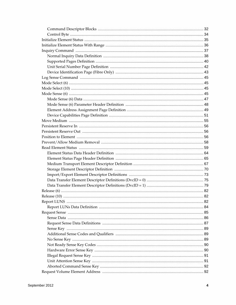
Command Descriptor Blocks ............................................................................................... 32
Control Byte ........................................................................................................................ 34
Initialize Element Status ........................................................................................................... 35
Initialize Element Status With Range ........................................................................................ 36
Inquiry Command ................................................................................................................... 37
Normal Inquiry Data Definition .......................................................................................... 38
Supported Pages Definition ................................................................................................. 40
Unit Serial Number Page Definition .................................................................................... 42
Device Identification Page (Fibre Only) ............................................................................... 43
Log Sense Command ............................................................................................................... 45
Mode Select (6) ......................................................................................................................... 45
Mode Select (10) ....................................................................................................................... 45
Mode Sense (6) ......................................................................................................................... 45
Mode Sense (6) Data ............................................................................................................ 47
Mode Sense (6) Parameter Header Definition ...................................................................... 48
Element Address Assignment Page Definition ..................................................................... 49
Device Capabilities Page Definition ..................................................................................... 51
Move Medium ......................................................................................................................... 55
Persistent Reserve In ................................................................................................................ 56
Persistent Reserve Out ............................................................................................................. 56
Position to Element .................................................................................................................. 56
Prevent/Allow Medium Removal ............................................................................................ 58
Read Element Status ................................................................................................................ 59
Element Status Data Header Definition ............................................................................... 64
Element Status Page Header Definition ............................................................................... 65
Medium Transport Element Descriptor Definition ............................................................... 67
Storage Element Descriptor Definition ................................................................................ 70
Import/Export Element Descriptor Definitions ................................................................... 73
Data Transfer Element Descriptor Definitions (DvcID = 0) ................................................... 75
Data Transfer Element Descriptor Definitions (DvcID = 1) ................................................... 79
Release (6) ................................................................................................................................ 82
Release (10) .............................................................................................................................. 82
Report LUNS ........................................................................................................................... 82
Report LUNs Data Definition .............................................................................................. 84
Request Sense .......................................................................................................................... 85
Sense Data .......................................................................................................................... 86
Request Sense Data Definitions ........................................................................................... 87
Sense Key ........................................................................................................................... 89
Additional Sense Codes and Qualifiers ............................................................................... 89
No Sense Key ...................................................................................................................... 89
Not Ready Sense Key Codes ................................................................................................ 90
Hardware Error Sense Key .................................................................................................. 90
Illegal Request Sense Key .................................................................................................... 91
Unit Attention Sense Key .................................................................................................... 91
Aborted Command Sense Key ............................................................................................. 92
Request Volume Element Address ........................................................................................... 92

September 2012 5
Reserve (6) ............................................................................................................................... 93
Reserve (10) ............................................................................................................................. 93
Send Diagnostic ....................................................................................................................... 93
Send Volume Tag ..................................................................................................................... 93
Test Unit Ready ....................................................................................................................... 94
Write Buffer ............................................................................................................................. 94
A Tape Drives and Media Types ........................................................................................... 95
Glossary ................................................................................................................................... 97
Index ........................................................................................................................................ 107

September 2012 6

September 2012 List of Figures 7
List of Figures
FIGURE 1-1 Example of a Library Configuration on the SCSI Bus .................................................. 16

8 ACSLS Interface Reference Manual September 2012

September 2012 List of Tables 9
List of Tables
TABLE 3-1 Supported Commands ............................................................................................... 31TABLE 3-2 6-Byte Command Descriptor Blocks ........................................................................... 33TABLE 3-3 10-Byte Command Descriptor Blocks.......................................................................... 33TABLE 3-4 12-Byte Command Descriptor Blocks.......................................................................... 33TABLE 3-5 Control Byte............................................................................................................... 34TABLE 3-6 Initialize Element Status Command............................................................................ 35TABLE 3-7 Initialize Element Status with Range Command ......................................................... 36TABLE 3-8 Inquiry Command ..................................................................................................... 37TABLE 3-9 Normal Inquiry Data.................................................................................................. 38TABLE 3-10 Supported Pages ........................................................................................................ 40TABLE 3-11 Unit Serial Number Page............................................................................................ 42TABLE 3-12 Mode Sense (6) Command.......................................................................................... 46TABLE 3-13 Mode Sense (6) Parameter Header .............................................................................. 48TABLE 3-14 Mode Sense (6) Element Address Assignment Page .................................................... 49TABLE 3-15 Device Capabilities Page ............................................................................................ 51TABLE 3-16 Move Medium Command .......................................................................................... 55TABLE 3-17 Position to Element Command ................................................................................... 56TABLE 3-18 Prevent/Allow Medium Removal Command ............................................................. 58TABLE 3-19 Read Element Status Command ................................................................................. 59TABLE 3-20 Element Status Data Header Definition ...................................................................... 64TABLE 3-21 Element Status Page Header....................................................................................... 65TABLE 3-22 Medium Transport Element Descriptor ...................................................................... 67TABLE 3-23 Storage Element Descriptor ........................................................................................ 70TABLE 3-24 Import/Export Element Descriptor ............................................................................ 73TABLE 3-25 Data Transfer Element Descriptor (DvcID = 0)............................................................ 76TABLE 3-26 Data Transfer Element Descriptor (DvcID = 1)............................................................ 79TABLE 3-27 Report LUNs command ............................................................................................. 83TABLE 3-28 Report LUNs Data Definition .................................................................................... 84TABLE 3-29 Request Sense Command ........................................................................................... 85TABLE 3-30 Request Sense Data .................................................................................................... 87TABLE 3-31 Sense Key Code Descriptions ..................................................................................... 89TABLE 3-32 Not Ready Sense Keys................................................................................................ 90TABLE 3-33 Hardware Error Sense Keys ....................................................................................... 90TABLE 3-34 Illegal Request Sense Keys.......................................................................................... 91TABLE 3-35 Unit Attention Sense Keys .......................................................................................... 91TABLE 3-36 Aborted Command Sense Keys .................................................................................. 92TABLE 3-37 Test Unit Ready Command ........................................................................................ 94

10 ACSLS Interface Reference Manual September 2012

September 2012 Preface 11
Preface
This manual is intended to be used by service representatives, hardware engineers, software engineers, and operating system designers and developers responsible for implementing StorageTek's version of the small computer system interface (SCSI) over Fibre Channel interface (FCP) for ACSLS 8.1.
This manual contains information about the small computer system interface, including SCSI characteristics, library features, SCSI bus operations, SCSI commands, status byte data, and sense data. This manual also contains information about the Fibre Channel interface, including Fibre Channel operations, command implementations, topologies, cables, and connectors.
Note – This manual does not describe the SCSI bus controls and commands or the Fibre Channel operations and commands for the tape drives in the library.
Access to Oracle SupportOracle customers have access to electronic support through My Oracle Support. For information, visit http://www.oracle.com/support/contact.html or visit http://www.oracle.com/accessibility/support.html if you are hearing impaired.

Access to Oracle Support
12 ACSLS Interface Reference Manual September 2012

September 2012 General Information 15
1
General Information
This chapter describes the small computer system interface (SCSI) and the Fibre Channel interface (FC) for ACSLS 8.x. This manual does not describe the Fibre Channel interface to the tape drives.
The SCSI Bus InterfaceThe libraries’ SCSI interface conforms to SCSI specifications and is accepted by:
• American National Standards Institute (ANSI X3.131)
• European Computer Manufacturing Association (ECMA-111)
• Federal Information Processing Standard (FIPS-131)
• International Standards Organization (ISO-9316)
Overview
The small computer system interface operates locally as an input and output (I/O) bus that uses a common command set to transfer controls and data to all devices. The main purpose of this interface, called the SCSI bus, is to provide host computer systems with connections to a variety of peripheral devices, including disk subsystems, tape subsystems, printers, scanners, CD-ROMs, optical devices, communication devices, and libraries.
The SCSI bus design for the library provides a peer-to-peer, I/O interface that supports up to 16 devices and accommodates multiple hosts.
Peer-to-peer interface communication can be from:
• Host to host
• Host to peripheral device
• Peripheral device to peripheral device
SCSI terms defining communication between devices on the SCSI bus include:
• Initiator is the device that requests an operation.
• Target is the device that performs the operation requested.

The SCSI Bus Interface
16 ACSLS Interface Reference Manual September 2012
Some targets are control units that can access one or more physical or virtual peripheral devices addressable through the control unit. These peripheral devices are called logical units and are assigned specific addresses or logical unit numbers (LUNs).
The library supports SCSI-3 commands.
The library and the tape drives have separate connections for attachment to the SCSI bus. Daisy-chain cables are available to interconnect devices on the SCSI bus but keep the total cable length to a minimum. FIGURE 1-1 is an example of a library and four tape drives that are daisy-chained to two initiators (or hosts).
Note – It is recommended that the drives be connected to a separate SCSI bus from the library.
FIGURE 1-1 Example of a Library Configuration on the SCSI Bus
LIBRARYSTORAGEMODULE
TAPEDRIVE
TAPEDRIVE
TAPEDRIVE
TAPEDRIVE
SCSI
BUS
INITIATOR
INITIATOR
L204_155

The SCSI Bus Interface
September 2012 General Information 17
Benefits
A small computer system interface also provides these benefits:
• Low overhead
• High transfer rates
• A high-performance buffered interface
• Conformance to industry standards
• Plug compatibility for easy integration
• Error recovery, parity, and sequence checking provides high reliability
• Provisions in the command set for vendor-unique fields
• Standard or common command sets with an intelligent interface that provides device independence
Implementation
Implementation of the SCSI bus for the library supports:
• 8-bit wide transfers, asynchronous; 16-bit wide selection
• Disconnect and reselect
• Multiple initiator
• Hard resets
• Single-ended LVD
• SCSI-3, 68-pin P-cable
Implementation for the library does not support:
• Soft resets
• Command queuing
• Command linking
• Asynchronous event notification
• Extended contingent allegiance

The Fibre Channel Standard
18 ACSLS Interface Reference Manual September 2012
The Fibre Channel StandardStorageTek’s implementation of Fibre Channel conforms to the American National Standards Institute (ANSI), National Committee for Information Technology Standards (NCITS) formerly X3.
Overview
• Serial connection
• Copper (electrical) or fiber (optical) transmissions
• Multiple protocols (such as SCSI, IP, HIPPI, IPI-3)
• Information transparent
• 100 MB/s data transfer rates (and higher)
• Scalable for media rates, distance, media, and protocols
Benefits
In 1994, the Fibre Channel Physical and Signaling Interface (FC-PH), or ANSI X3.230-1994, was completed, differing from every other architecture at the time. This specification married the strengths of channels, including high throughput and low overhead, with the strengths of networks, including flexibility, long distance capability, and high connectivity.
Implementation
Library:
• Arbitrated loop
• FCP (SCSI-3) command set for medium changer devices
• Class 3 level of service
• Private Loop operation
• Public Loop operation
• Direct fabric attach operation
• Hard-assigned port addresses (AL-PA)
• Basic and extended link services
• Connections to an external hub (or switch)
• Data transfer rates of 100 MB/s
• Standard approved length shortwave fibre optic cables
• Multimode laser operating at 780 nanometers (shortwave) non–OFC
The Fibre Channel Standard
September 2012 General Information 19
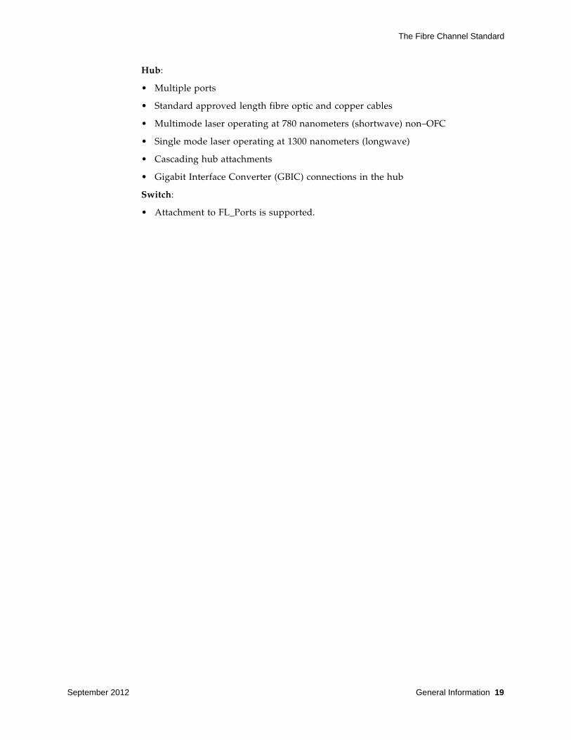
Hub:
• Multiple ports
• Standard approved length fibre optic and copper cables
• Multimode laser operating at 780 nanometers (shortwave) non–OFC
• Single mode laser operating at 1300 nanometers (longwave)
• Cascading hub attachments
• Gigabit Interface Converter (GBIC) connections in the hub
Switch:
• Attachment to FL_Ports is supported.

The Fibre Channel Standard
20 ACSLS Interface Reference Manual September 2012
September 2012 ACSLS 8.1 Logical Libraries 21
2
ACSLS 8.1 Logical Libraries
The ACSLS 8.1 Logical Library (referred to in this document simply as “logical library”) is a subset of one or more connected physical libraries (drives and volumes). It is currently presented over two interfaces: one is the SCSI and the other is the ACSLS 8.1 Graphical User Interface (referred to in this document simply as “GUI”). This document covers the SCSI/FCP interface and mentions the GUI only where it has impact on the SCSI interface. For more information on the management of logical libraries, refer to the ACSLS 8.1 documentation.
The ACSLS 8.1 system (referred to in this document simply as the “system”) presents each logical library as a SCSI Media Changer (SMC) device. Each device appears as a separate LUN on a Fibre Channel (FC) target port contained on the system. Initiator mode FCP SCSI applications (referred to in this document simply as hosts or host applications) attach to the system through a FC SAN and communicate with the logical library using the SCSI commands described in this document. Also attached to the system are one or more physical libraries. A physical library can be any type of library supported by the system. This may include both SCSI and non-SCSI (HLI) libraries. A logical library uses some or all of the resources of one or more physical libraries. A logical library cannot span more than one physical library unless the physical libraries are connected together with a pass through mechanism. The system presents each logical library as a single SCSI library on its own LUN even if the logical library has been configured to use resources from more than one physical library. The system provides LUN masking so that each host sees only the logical libraries that have been configured for it. Only one host connection per logical library is allowed. With this restriction, reservations and reservation conflicts are not possible and are therefore not described in this document.
A logical library is created by a System Administrator (referred to in this document simply as the “administrator”) using the GUI. The resources of the library are mapped by the system to real resources of the associated physical library (s). This is described in more detail under Elements of a Logical Library below. From the perspective of the SCSI interface, a logical library behaves very much the same as a real SCSI Media Changer, but there are some differences. High level descriptions of these differences are described in this chapter. For detailed description of each command see “SCSI Commands”.

Elements of a Logical Library
22 ACSLS Interface Reference Manual September 2012
Elements of a Logical LibraryLike a real SCSI library, a logical library consists of the following elements:
• One hand element
• One or more import/export elements¦
• Zero or more drive elements
• One or more storage elements
The hand element, storage elements, and import/export elements are all logical entities; they do not have corresponding physical resources in the physical library. Drive elements, however, do correspond one to one to a real physical drive in the physical library. Below is a description of each element and the considerations that a host application may need to understand in order to properly control a logical library.
Hand Element
All Logical libraries have one hand element at SCSI element address 0. This is a logical entity only, i.e. it does not correspond to any physical hand. A Read Element Status can be issued for this address but it will always appear to be empty. The source or destination of a Move Medium command cannot be the hand element. This is consistent with the response given for the Device Capabilities Page of the Mode Sense command.
Import / Export Elements
Each logical library has a configurable number of consecutive import/export elements starting at SCSI element address 10. The maximum number of import/export elements that can be configured is 490. These elements do not correspond to physical cells in the physical library. The actual number of elements that are configured can be queried using the Mode Sense(6) command.
Volume Movement
Volumes can be moved to any configured import/export element using the Move Medium command; however, the elements cannot be used as a place to store a volume. This is consistent with the response given for the Device Capabilities page of the Mode Sense command. When a volume is moved to an import/export element, it is automatically unassigned from the logical library. From the SCSI interface perspective, after the move the volume no longer exists in the logical library, however it is still present in the physical library. Read Element Status for import/export elements always report that the element is empty. Therefore, logical library, import/export elements can be conceptually thought of as one way chutes where volumes can be sent through in order to eject them from the library. In order to provide compatibility with a physical SCSI library, the next command issued following a successful Move Medium command to an import/export element causes a unit attention condition with the following sense information:
Sense Key 6h (Unit Attention)ASC / ASCQ 28h / 01h (Cap Element Accessed)

Elements of a Logical Library
September 2012 ACSLS 8.1 Logical Libraries 23
Presenting this unit attention tells the host that one or more import/export elements may have been accessed manually by an administrator. In this case, if the host elects to issue a Read Element Status for the import/export element that was just used in the previous Move Medium command, it will find that the element is empty. The host application can then assume that the volume has been removed. This is the same behavior a host would experience with a physical library if the real CAP is accessed. Note, however, that issuing the Read Element Status in response to the unit attention is not necessary. If the previous Move Medium had completed successfully, a host application can safely assume that the volume has been logically ejected from the library and recovery from the unit attention can be simply to retry the Move Medium command. Import/export elements never contain a volume.
As indicated in the Mode Sense Device Capabilities Page, movement from import/export cells is not supported. Any Move Medium command that uses and import/export element for the source address will fail with:
Sense Key 5h (Illegal Request)ASC / ASCQ 21h / 01h (Invalid Element)
This means that import/export elements are never used to enter volumes into a logical library. They are only used as a way for SCSI host applications to programmatically eject volumes. Volumes can only be entered directly into a logical library to available storage elements through an assignment operation performed by an administrator using the GUI. This is described in more detail under Storage Elements below.
Capacity Changes
Whenever an administrator changes the number of import/export elements configured for a logical library using the GUI, the system raises a unit attention condition with the following sense information:
Sense Key 6h (Unit Attention)ASC / ASCQ 2Ah / 01h (Mode Parameters Changed)
Host applications must issue Mode Sense to determine the new number of import/export elements available.
Prevent/Allow Considerations
With a real SCSI library, the Prevent/Allow Medium Removal command allows a host to lock and unlock access to a physical CAP. Since a logical library does not have a physical CAP (it has logical import/export elements but they do not correspond to a physical CAP) this command is supported for compatibility purposes and will always succeed. It is essentially a NOOP.
Storage Elements
Each logical library has a configurable number of consecutive storage elements starting at SCSI element address 1000. The maximum number of storage elements that can be configured is 64,535. Note that a logical library’s storage element count can be configured to be greater than or less than the physical library (s) cell count. These elements are logical and do not correspond directly to physical cells of the physical library. Volumes can be moved to any unoccupied storage element using the Move Medium command. Even if the source of the move is an occupied storage

Elements of a Logical Library
24 ACSLS Interface Reference Manual September 2012
element, no robotic movement occurs, only the association between the logical SCSI element address and the actual physical location of the volume in the physical library is updated. If movement is to or from a valid drive element, robotic activity does occur in the physical library since logical library drives correspond one for one with physical drives. See Drive Elements for more details.
Assigning and Unassigning Volumes
When a logical library is created by the administrator using the GUI, all storage elements are initially empty. To populate volumes into the empty storage elements an administrator must perform an assignment operation using the GUI. Likewise, to remove volumes from occupied storage elements the administrator may perform an unassign operation. Volumes can also be logically removed via the Move Medium command when the destination is an import/export element. See Import/Export Elements.
Each time a volume is either assigned to or unassigned from a logical library, the system raises a unit attention condition on the interface for the next SCSI command received as follows
Sense Key 6h (Unit Attention)ASC / ASCQ 28h / 00h (Not Ready-to-Ready Transition)
This emulates the behavior of a physical library when an operator opens the door and either manually adds or removes volumes directly to/from storage elements. When the door is closed, the physical library re-inventories its contents and presents a Not-Ready-To-Ready Unit Attention when it has finished. For logical libraries, this happens instantly after assign or unassign operations. After receiving this unit attention a host application should issue Read Element Status for all storage elements to determine the current contents of the logical library.
Volume Movement
When a volume is moved from a storage element (via the Move Medium command) to another location, the action carried out by the system depends on the destination element type as follows:
• Hand element - not allowed.
• Import/export element - the action carried out is as described under Import/Export Elements above.
• Drive element - the volume is moved from the associated physical library storage location to the physical drive in the physical library that corresponds to the SCSI element address specified in the command.
• Storage element - no robotic movement takes place, only the volumes associated SCSI Element address is changed.
Capacity Changes
Whenever an administrator successfully changes the number of storage elements configured for a logical library (using the GUI), and that change does not result in any volumes changing their SCSI element address, the system raises a unit attention condition on the interface for the next SCSI command received as follows:

Elements of a Logical Library
September 2012 ACSLS 8.1 Logical Libraries 25
Sense Key 6h (Unit Attention)ASC / ASCQ 2Ah / 01h (Mode Parameters Changed)
Host applications must issue Mode Sense to determine the new number of storage elements available but can safely assume that the current volume inventory has not changed locations.
If the change to the number of configured storage elements does cause volumes to be logically moved to different storage elements (this can happen if the capacity is decreased causing volumes to be logically moved to other unused storage elements), the system raises two unit attention conditions for the next two commands received as follows:
• Sense Key 6h (Unit Attention)ASC / ASCQ 28h / 00h (Not Ready-To-Ready Transition
• ASC / ASCQ 2Ah / 01h (Mode Parameters Changed)
In this case a client application should issue both a Mode Sense command (to determine the new number of storage elements available) and a Read Element Status to determine the contents of each storage element. If the client application ignores this unit attention and continues to use information about the library that it had obtained previously, subsequent commands may fail unexpectedly; therefore, it is important that a client application reconcile both the configuration and inventory of the library after receiving the Not Ready-to-Ready Transition and Mode Parameters Changed unit attentions.
Drive Elements
Each logical library has a configurable number of drive elements starting at element address 500. The maximum number of drive elements that can be configured is 500. The response to a Read Element Status always includes an entry for every drive element currently configured; however, each drive element may or may not be associated with a physical drive. If the element is not currently associated with a physical drive the ED bit (byte 9, bit 3) is set to 1 and the Access bit (byte 2, bit 3) is set to 0 in the Read Element Status response.
Capacity Changes
Initially, the number of drive elements is set when the logical library is created. Subsequently, this number can be changed by the administrator (using the GUI). If this number is changed, the system raises a unit attention condition on the interface for the next SCSI command received as follows:
Sense Key 6h (Unit Attention)ASC / ASCQ 2Ah / 01h (Mode Parameters Changed)
If the count is decreased and results in any association change (between drive element address and physical drive) then the system precedes the Mode Parameters Changed unit attention with:
Sense Key 6h (Unit Attention)ASC/ASCQ 28h / 00h (Not Ready-To-Ready Transition)

Command Support
26 ACSLS Interface Reference Manual September 2012
If the host only receives the Mode Parameters Changed unit attention then it should issue Mode Sense to determine the new number of drive elements available. It can assume that no element address associations have changed. However, if the Not-Ready-To-Ready unit attention is received, the host should be sure to update its drive configuration with current information obtained via Read Element Status.
Adding and Removing Drives
Physical drives can be added or removed from a logical library by the administrator using the GUI. When a drive is added, it is automatically assigned to the next available drive element address starting with the lowest address. When a drive is removed, the system disassociates the physical drive from the drive element (the ED bit will be set to 1 and the Access bit set to 0 in a Read Element Status response) but the number of drive elements (as reported by Mode Sense) remains unchanged. No unit attention conditions are raised.
Drive Failures
A drive failure condition (as perceived by the host application) will result from any one of the following actions:
• The drive is varied offline by the administrator.
• The drive is removed from the logical library by the administrator.
• The drive is physically powered off or disconnected.
• The drive is experiencing a physical hardware failure.
All of the above conditions result in the following:
The descriptor entry in the Read Element Status response has the Except bit (byte 1, bit 2) set to 1 and the Access bit set to 0 and the ASC/ASCQ fields (bytes 4 and 5) are set to 04h / 02h (Hardware Error, Tape Drive).
A Move Medium command that addresses the drive will fail with
Sense Key 4h (Hardware Failure)ASC/ASCQ 40h / 02h (Hardware Error, Tape Drive).
Command SupportLogical libraries do not support all SMC commands. Commands that deal primarily with physical hardware are not supported, i.e. Mode Sense (10). Some commands are supported but don’t actually do anything (i.e., Initialize Element Status). Other commands are supported but only for a subset of the possible response pages, i.e. Mode Sense (6). The intent is to provide command emulation that will allow for a wide adoption of logical libraries with little or no change to host applications. Unsupported commands will fail with Check Condition Sense Key 05h (Illegal Request), ACS / ACSQ 20h / 00h (Invalid Command). The commands listed below are ones that may behave differently then they would for a real library.

Command Support
September 2012 ACSLS 8.1 Logical Libraries 27
Inquiry
The Inquiry data for a logical library is unique, i.e., it does not report that it is a known real library type. Also, the device identification page uses a NAA type 6 format using the logical library unique serial number as part of the vendor specific extension. This provides a way for clients to uniquely identify a library regardless of which target port the device is presented on.
Serial numbers for logical libraries consist of 12 ascii numbers. The format is as follows:
SSSSSSSSNNNN where:
SSSSSSSS is the unique software serial number of the system.NNNN is the number of the library partition within the system (0-9999)
If an Inquiry command is received from a host initiator on a lun that is not currently mapped to a logical library, Inquiry returns a response with the Peripheral Qualifier set to 011b and Peripheral Device Type set to 1fh. Lun mapping is established by an administrator using the GUI.
Mode Sense (6)
The Mode Sense (6) command supports the Element Address Assignment (1Dh) and Device Capabilities (1Fh) pages only.
Note – A logical library does not support element storage for I/E elements and an I/E element cannot be the source of a Move Medium command. The Move Medium command will fail with CHECK_CONDITION, SenseKey Illegal Request (5h), and ACS/ASCQ Invalid Element (2 1/01h)
Move Medium
Move Medium commands which do not involve a drive element complete much faster for a logical library than for a physical library.
Move Medium to/from drive elements cause real robotic activity in the physical library. The time required before completion of the move is reported depends on the Fast Load setting at the time the command is received (this setting is found under "Preferences" in the ACSLS GUI).
Move Medium commands to/from import export elements behave differently than a real library. These differences are described in detail under “Import / Export Elements” on page 22.
Prevent / Allow Medium Removal
Since a logical library does not contain a physical CAP, this command is supported for compatibility but always returns “success”.

Command Support
28 ACSLS Interface Reference Manual September 2012
Read Element Status
The format of the Primary Volume Tag Information field can be in one of four formats, 6 character, 8 character suffix, and 8 character prefix. The format to be used is an attribute of the logical library that can be set by the administrator using the GUI. This is described in detail under the VolTag field of the ReadElementStatus CDB in the “SCSI Commands” chapter.
Report LUNs
The system presents each logical library as a separate LUN on one of the systems’ fibre channel target ports. The system provides LUN masking by allowing only specified initiators access to logical libraries. Initiators are identified using their FC world wide port name (WWPN). Using the GUI, an administrator must establish a mapping between an initiator (I), a target port (T), and a LUN (L). These mappings are saved by the system so that the logical library will always be presented on the same target port and LUN for the initiator. Each initiator is given its own LUN space starting with LUN 0. It is important to note that logical libraries can appear on LUNs other than 0. The first library mapped to an initiator will be assigned LUN 0, the next (on the same target port) will be assigned LUN 1 and so on.
The Report LUNs command will report the LUNs available to the requesting initiator. The command response includes the LUN number for each logical library that has been mapped for the requesting initiator. The LUN numbers are not guaranteed to be consecutive.
Whenever a mapping change is made by an administrator using the GUI, the system raises the following unit attention to the affected initiator:
Sense Key 6h (Unit Attention)ACS / ACSQ 3Fh / 0Eh (Report LUNS Data Has Changed)
Request Sense
Logical libraries use an FC-2 conforming transport that provides autosense. This means that sense data for a failed command is always returned with a Check Condition status in the command response and is never saved by the target. Therefore, Request Sense will always return Sense Data with a Sense Key set to No Sense and ASC/ASCQ fields set to 0. The Request Sense command still documents all the Sense Data that can be returned from the other commands.
Reserve / Release
The Reserve and Release commands are purposely not supported in ACSLS 8.1. In release 1.1, each logical library can be mapped to a maximum of one initiator. Therefore, every logical library in release 1.1 will be exclusively owned by a single initiator and Reserve / Release would have no meaning. These commands will be rejected with CHECK_CONDITION.

Tape Drives and Media Types Supported
September 2012 ACSLS 8.1 Logical Libraries 29
Tape Drives and Media Types Supported A logical library can contain any of the drives and media that can reside in any of the SL series of StorageTek libraries (SL500, SL8500, or SL3000). Note that drives and media that a logical library can support is a superset of all the drive and media types supported by these libraries. An individual logical library would only ever contain a subset of these types. Drives and media (volumes) are allocated to a logical library by the administrator using the GUI. See “Tape Drives and Media Types” on page 95 for a list.

Tape Drives and Media Types Supported
30 ACSLS Interface Reference Manual September 2012

September 2012 SCSI Commands 31
3
SCSI Commands
This chapter lists and describes SCSI command structures for a logical library. TABLE 3-1 contains a list of the commands, command codes, and page numbers. In the following table, the Supported column displays the commands as one of the following: S (supported) or N (not supported).
TABLE 3-1 Supported Commands
Command Hex Code Supported Page
Initialize Element Status 07 S on page 35
Initialize Element Status With Range E7, 37 S on page 36
Inquiry Command 12 S on page 37
Log Sense Command 4D N on page 45
Mode Select (6) 15 N on page 45
Mode Select (10) 55 N on page 45
Mode Sense (6) 1A S on page 45
Mode Sense (10) 5A N on page 55
Move Medium A5 S on page 55
Persistent Reserve In 5E N on page 56
Persistent Reserve Out 5F N on page 56
Position to Element 2B S on page 56
Prevent/Allow Medium Removal 1E S on page 58
Read Element Status B8 S on page 59
Release (6) 17 N on page 82
Release (10) 57 N on page 82
Report LUNS A0 S on page 82
Request Sense 03 S on page 85
Request Volume Element Address B5 N on page 92

Implementation Requirements
32 ACSLS Interface Reference Manual September 2012
Implementation Requirements The initiator sends commands to the target using command descriptor blocks (CDBs). The command descriptor blocks contain a format that includes:
■ Operation code■ Command parameters
• Control byte
Note – The library is SCSI-3 compliant.
For some commands, a list of parameters accompanies the request during the Data Out phase.
For all commands, if there is an invalid parameter in the command descriptor block, then the device terminates the command without altering the medium.
Command Descriptor Blocks
Initiators use command descriptor blocks (CDBs) to communicate commands to the targets. The library supports three types of command descriptor blocks:
■ 6-byte commands (TABLE 3-2) ■ 10-byte commands (TABLE 3-3)
• 12-byte commands (TABLE 3-4)
The structure for all command descriptor blocks is:
The first byte contains a: ■ Group Code that provides 8 groups of commands
• Command Code that provides 32 command codes for each group
The second byte in all command descriptor blocks:
• Starts the command parameters
Any additional bytes:
• Contains command parameters
The last byte in all command descriptor blocks:
• Contains the control byte (TABLE 3-5)
Reserve (6) 16 N on page 93
Reserve (10) 56 N on page 93
Send Diagnostic 1D N on page 93
Send Volume Tag B6 N on page 93
Test Unit Ready 00 S on page 94
Write Buffer 3B N on page 94
TABLE 3-1 Supported Commands (Continued)
Command Hex Code Supported Page

Implementation Requirements
September 2012 SCSI Commands 33
TABLE 3-2 6-Byte Command Descriptor Blocks
Byte
Bit
7 6 5 4 3 2 1 0
0Group Code (of operation code)
Command Code (of operation code)
1 Command Parameters
2–4 Command Parameters
5 Control Byte
TABLE 3-3 10-Byte Command Descriptor Blocks
Byte
Bit
7 6 5 4 3 2 1 0
0Group Code (of operation code)
Command Code (of operation code)
1 Command Parameters
2–8 Command Parameters
9 Control Byte
TABLE 3-4 12-Byte Command Descriptor Blocks
Byte
Bit
7 6 5 4 3 2 1 0
0Group Code (of operation code)
Command Code (of operation code)
1 Command Parameters
2–10 Command Parameters
11 Control Byte

Implementation Requirements
34 ACSLS Interface Reference Manual September 2012
Control Byte
The control byte is the last byte of every command descriptor block (see TABLE 3-5).
TABLE 3-5 Control Byte
Byte
Bit
7 6 5 4 3 2 1 0
5, 9, or 12 Vendor Specific Reserved NACA
(0) Flag (0)
Link (0)
Control Byte Definitions:
Vendor Specific Provides additional information about the device or for a command.
NACA The normal auto contingent allegiance bit controls the rules for handling an auto contingent condition caused by a command. This bit is set to 0 to indicate that if a contingent allegiance condition occurs, the command will return a check condition.
Flag (not supported) This bit causes an interrupt in the initiator allowing a device to respond with intermediate status. This bit is not supported and should be 0.
Link (not supported) Allows devices that support command linking to continue the I/O process. This bit is not supported and should be 0.

Initialize Element Status
September 2012 SCSI Commands 35
Initialize Element Status The host uses the Initialize Element Status command (07) to request an inventory of the cartridge tapes held in the library. The library accepts this command for compatibility, but does not perform any action. The command descriptor block is validated even though the command is not used. An initiator can obtain inventory information for the library by using the Read Element Status command.
TABLE 3-6 Initialize Element Status Command
Byte
Bit
7 6 5 4 3 2 1 0
0 Operation Code (07h)
1 Reserved (00h)
2 Reserved (00h)
3 Reserved (00h)
4 Reserved (00h)
5 Control Byte (00h)

Initialize Element Status With Range
36 ACSLS Interface Reference Manual September 2012
Initialize Element Status With Range The Initialize Element Status With Range command (37) is a request from the host to perform an inventory of a portion of the cartridge tapes within the library. The library accepts this command for compatibility, but does not perform any action.
The library performs an audit of and maintains the inventory upon power up. The library also performs an audit after some one has opened and closed the front door.
The command descriptor block is validated even though the command is not used. No checks are made of ignored fields (see Table 3-7).
An initiator can obtain inventory information for the library by using the Read Element Status command.
TABLE 3-7 Initialize Element Status with Range Command
Byte
Bit
7 6 5 4 3 2 1 0
0 Operation Code (37h)
1 Reserved (00h) Fast Range
2to3
(MSB)Element Address
(LSB)
4 Reserved (00h)
5 Reserved (00h)
6to7
(MSB)
Number of Elements
(LSB)
8 Reserved (00h)
9 Control Byte (00h)
Initialize Element Status with Range Definitions:
Fast Ignore this field.
Range Ignore this field.
Element Address Ignore this field.
Number of Elements Ignore this field.

Inquiry Command
September 2012 SCSI Commands 37
Inquiry Command The Inquiry command (12) requests that the library send to the initiator information regarding the library’s parameters (see TABLE 3-8).
The library terminates the Data In phase when it has transferred either the number of bytes specified by the Allocation Length field or all of the available inquiry data, whichever is less.
TABLE 3-8 Inquiry Command
Byte
Bit
7 6 5 4 3 2 1 0
0 Operation Code (12h)
1Reserved (00h) CmdDt
(0)EVPD
2 Page Code
3to4
MSB
Allocation Length
LSB
5 Control Byte (00h)
Inquiry Command Definitions:
CmdDt The library returns a value of 0, indicating command support data is not supported.
EVPD The enable vital product data bit indicates the type of inquiry data the initiator is requesting. Supported values are:
0 = Request for normal inquiry data 1 = Request for vital support product data page
Page Code If the EVPD value is 0, this field must be 00h. If the EVPD value is 1, this field must be:
00h = Supported vital product pages80h = Unit serial number page83h = Device identification page (Fibre only)
Allocation Length The allocation length field specifies the number of bytes the initiator has allocated for data returned from the Inquiry command.
A value of 0 indicates that no inquiry data is to be transferred. This condition is not considered an error.

Inquiry Command
38 ACSLS Interface Reference Manual September 2012
The data length for the normal inquiry data the library returns is 24h (36d) bytes. The data length for page 0 is 07h (7d). The data length for the unit serial number page (80h) is 0fh (15d) bytes. The data length for the device identification page (83h) is 18h (24d).
Note – The Inquiry command returns check condition status only when the requested data cannot be returned. This command will not clear any pending unit attention conditions.
Normal Inquiry Data Definition
For the Inquiry command, the library returns 24h (36d) bytes of data in the format shown in TABLE 3-9.
TABLE 3-9 Normal Inquiry Data
Byte
Bits
7 6 5 4 3 2 1 0
0 Peripheral Qualifier Peripheral Device Type
1RMB (1)
Reserved (0)
2 Version (05h)
3
Reserved (0) NormACA (0)
HiSup
(1)
Response Data Format (2)
4 Additional Length (n-4)
5SCCS (0)
ACC (0)
ALUA (0) 3PC (0) Reserved
6
BQue (0)
EncServ (0)
VS (0)
MultiP (0)
MChngr (0)
Reserved (0)
7
RelAdr(0)
Reserved (0) LINKED(0)
RSVD (0)
CmdQue (0)
SftRe(0)
8to15
(MSB)Vendor Identification
(LSB)
16to31
(MSB)Product Identification
(LSB)
32to35
(MSB)Product Revision Level
(LSB)

Inquiry Command
September 2012 SCSI Commands 39
Normal Inquiry Data Definitions:
Peripheral Qualifier The library returns a value of 000b, which indicates that the library is a single logical unit number (LUN). If a logical library is not currently mapped to the lun, this field is set to 011b.
Peripheral Device Type
The library returns a value of 8h, which indicates that the library is a medium changer device. If a logical library is not currently mapped to the lun, this field is set to 1fh.
RMB Removable Medium; a value of 1 indicates the medium is removable.
Device-Type Modifier
A value of 0 indicates there are no modifiers for the library.
Version The library returns a value of 5h, which indicates compliance to SCSI-3
NormACA The Normal Auto Contingent Allegiance (NACA) bit controls the rules for handling an auto contingent condition caused by a command.
The library returns a value of 0, indicating it does not support setting the NACA bit to one.
HiSup The library returns a value of 1, indicating it uses the hierarchical addressing model to assign LUNs to logical units.
Response Data Format
A value of 2 indicates the data found is in accordance with the SCSI-3 specification.
Additional Length A value of 1fh indicates there are 24h (36) bytes of Inquiry data available to the initiator.
SCCS The library returns a value of 0, indicating the library does not contain an embedded storage array controller component.
ACC The library returns a value of 0, indicating it does not contain an access control coordinator that may be addressed through this logical unit.
ALUA The library returns a value of 0 for the asymmetrical logical unit access field, indicating asymmetric logical unit access is not supported.
3PC The library returns a value of 0, indicating third-party commands are not supported.
BQUE The library returns a value of 0, indicating basic queuing is not supported.
VS Vendor Specific bit is set to 0, indicating there is no vendor-specific information with this command.
MultiP The library returns a value of 0, indicating multi-port attachments are not supported.
MChngr The library is not embedded in or attached to a medium transport element and returns a value of 0.
RelAdr The library returns a value of 0 for the relative addressing bit, indicating relative addressing is not supported.
LINKED The library returns a value of 0 for the LINKED command bit, indicating linked commands are not supported.

Inquiry Command
40 ACSLS Interface Reference Manual September 2012
Error Conditions:
• The library returns Check Condition status for the Inquiry command only when a severe error occurs. To recover from a Check Condition status report on the Inquiry command, verify that the Inquiry CDB is OK, and retry the Inquiry command.
Supported Pages Definition
The library returns 7d bytes of supported page data in the format shown in TABLE 3-10.
CmdQue The library returns a value of 0, indicating Command Queing is not supported.
SftRe The library returns a value of 0, indicating Soft Reset is not supported.
Vendor Identification
Contains the ASCII character sequence “SUN” followed by blanks. If the specified logical unit is not supported, this field contains all blanks.
Product Identification
This field contains the ASCII character sequence “ACSLS-SCSI” followed by blanks.
Product Revision Level
For ACSLS, the initial product revision level is 1000.
TABLE 3-10 Supported Pages
Byte
Bit
7 6 5 4 3 2 1 0
0 Peripheral Qualifier (0) Peripheral Device Type (8)
1 Page Code (00h)
2 Reserved (00h)
3 Additional Page Length (03h)
4 Supported Page (00h)
5 Supported Page (80h)
6 Supported Page (83h)
Supported Pages Definitions:
Peripheral Qualifier The library returns a value of 000b, which indicates that the library is a single logical unit number (LUN). If a logical library is not currently mapped to the lun, this field is set to 011b.
Peripheral Device Type
The library returns a value of 8h, which indicates that the library is a medium changer device. If a logical library is not currently mapped to the lun, this field is set to 1fh.

Inquiry Command
September 2012 SCSI Commands 41
Page Code Identifies the page as the supported pages (00h).
Page Length Indicates that three vital pages are supported (03h).
Supported Page The first supported page value is set to
00h = Indicates the first vital page is page 0 (current page) 80h = Indicates the second vital page (unit serial number, on page 42) 83h = Indicates the third vital page (device identification, on page 43)

Inquiry Command
42 ACSLS Interface Reference Manual September 2012
Unit Serial Number Page Definition
TABLE 3-11 Unit Serial Number Page
Byte
Bit
7 6 5 4 3 2 1 0
0 Peripheral Qualifier (0) Peripheral Device Type (8)
1 Page Code (80h)
2 Reserved (00h)
3 Additional Page Length (0Ch)
4to15
(MSB)Unit Serial Number
(LSB)
Unit Serial Number Page Definitions:
Peripheral Qualifier The library returns a value of 000b, which indicates that the library is a single logical unit number (LUN). If a logical library is not currently mapped to the lun, this field is set to 011b.
Peripheral Device Type
The library returns a value of 8h, which indicates that the library is a medium changer device. If a logical library is not currently mapped to the lun, this field is set to 1fh.
Page CodeThis field is set to 80h, identifying the page as the unit serial number page.
Additional Page Length
This field is set to 0Ch, the number of bytes in the product serial number.
Unit Serial Number Serial numbers for logical libraries consist of 12 ASCII numeric (0-9) characters that uniquely identify the library. The format is as follows:
SSSSSSSSNNNN where:SSSSSSSS is the unique software serial number of the system.NNNN is the ID of the logical library partition within the system (0-9999).

Inquiry Command
September 2012 SCSI Commands 43
Device Identification Page (Fibre Only)
The library returns 24 bytes of device identification page data (page 83h) in the format shown below.
Byte Bit
7 6 5 4 3 2 1 0
0 Peripheral Qualifier (0) Peripheral Device Type (8)
1 Page Code (83h)
2 Reserved
3 Page Length (n-3=14h)
4 Reserved Code Set (1h)
5 Reserved Association (0h) Identifier Type (3h)
6 Reserved
7 Identifier Length (10h)
8 NAA (6h) (MSB)
9 IEEE Company ID (00104Fh)
10
11 (LSB) (MSB)
12
thru
15
Vendor Specific ID (0000004A6h)
16
thru
23
(MSB)
Vendor Specific ID Extension
(LSB)

Inquiry Command
44 ACSLS Interface Reference Manual September 2012
VPD page 83h returns a NAA type 6 IEEE Registered Extended identifier to uniquely identify the logical library.
• Code Set
• Association
• Identifier Type
• Identifier Length
• IEEE Company ID
This field contains the 24 bit canonical form Object Unique Identifier (OUI) for StorageTek assigned by the IEEE, i.e. 00104Fh.
• Vendor Specific ID
The VSID encoding is 0000004A6h, which is the hexadecimal representation of the company unique product code within StorageTek for StorageTek ACSLS 8.1, i.e. 1190d.
• Vendor Specific ID Extension
This field contains a hexadecimal encoding of the serial number. Each character of the serial number is represented in a 4 bit nibble. For example, a library with serial number “000012400002” the VSID Extension encoding would be 0000000012400002h.
1h Identifier field contains binary values
0h The Identifier field is associated with the addressed logical unit
3h The Identifier field contains an NAA type identifier that is compatible with a Name_Identifier defined in FC-FS
10h The NAA type 6h identifier, IEEE Registered Extended, has a fixed length of 16 bytes

Log Sense Command
September 2012 SCSI Commands 45
Log Sense Command This command is not supported.
Mode Select (6)This command is not supported.
Mode Select (10)This command is not supported.
Mode Sense (6)The Mode Sense (6) command (1A) enables the library to report its operating mode parameters to the initiator (see TABLE 3-12). The initiator can request one page or all pages of the mode parameters.
The Mode Sense (6) command only supports the Element Address Assignment (1Dh) and Device Capabilities (1Fh) pages. A library can be dynamically changed by the administrator using the GUI. Such changes include:
• increasing or decreasing the number of storage elements
• increasing or decreasing the number of import / export elements
• adding or removing drives
Whenever the administrator makes any of these changes, the system presents a Unit Attention to the client application with the following sense information:
Sense Key 6h (Unit Attention)ASC / ASCQ 2Ah / 01h (Mode Parameters Changed)
Upon receipt of this Unit Attention, the client application should re-configure the library by using information returned by the Mode Sense command.

Mode Sense (6)
46 ACSLS Interface Reference Manual September 2012
TABLE 3-12 Mode Sense (6) Command
Byte
Bit
7 6 5 4 3 2 1 0
0 Operation Code (1A)
1Reserved (00h) DBD
(1) Reserved (0)
2 Page Control Page Code
3 SubPage Code (00h)
4 Allocation Length
5 Control Byte
Mode Sense (6) Command Definitions:
DBD Disable Block Descriptors should be set to 1 to indicate that block descriptor should not be returned.
Page Control Defines the type of parameters to be returned for the Mode Sense command, values include:
0h (00b) = Current Values: The library returns the current parameter values. Since Mode Select is not supported, the current values will always be equal to the default values.
1h (01b) = Changeable Values Not supported. The command terminates with Check Condition status and sense key of Illegal Request (5h) and ASC set to Invalid Field in CDB (24h).
2h (10b) = Default Values: The library returns the default values. Since Mode Select is not supported, the default values will always be equal to the current values.
3h (11b) = Saved Values: The library returns the saved values.Not supported. The command terminates with Check Condition status and sense key of Illegal Request (5h) and ASC set to Invalid Saving Parameters Not Supported (39h).

Mode Sense (6)
September 2012 SCSI Commands 47
Mode Sense (6) Data
The library returns the following mode sense data:
• A four-byte Mode Parameter Header followed by
• One mode page or all mode pages in the order specified in the Page Code list. The mode pages available are those defined for medium changers in the Fibre Channel standard, including an Element Address Assignment page and a Device Capabilities page.
• The data can be truncated to the length specified in the allocation length field.
Page Code Specifies which pages the library returns, including:
1Dh = Element Address Assignment page
1Fh = Device Capabilities page
3Fh = All pages (in the above order)
SubPage Code Not supported.
Allocation Length Specifies the length of the parameter list the library returns. The maximum length is 2Ch (44d) bytes.The length varies based on the Page Code selected: ■ 4 bytes for the parameter list header (always present)■ 20 additional bytes for the Element Address Assignment page■ 20 additional bytes for the Device Capabilities page
Note – The library transfers the number of bytes specified by the Allocation Length or the available Mode Sense data, whichever is less.

Mode Sense (6)
48 ACSLS Interface Reference Manual September 2012
Mode Sense (6) Parameter Header Definition
The following table shows the Mode Sense Parameter Header page.
TABLE 3-13 Mode Sense (6) Parameter Header
Byte
Bit
7 6 5 4 3 2 1 0
0 Mode Data Length
1 Reserved
2 Reserved
3 Block Descriptor Length (00h)
Mode Sense (6) Parameter Header Page Definitions:
Mode Data Length This field indicates the number of bytes of parameter information available to be transferred to the initiator, regardless of the allocation length. This field excludes the Mode Data Length byte but includes three additional Mode Parameter Header bytes and any mode pages that follow.
Block Descriptor Length
The library does not support block descriptors (00h).

Mode Sense (6)
September 2012 SCSI Commands 49
Element Address Assignment Page Definition
This table defines the Element Address Assignment page of the Mode Sense (6) command.
TABLE 3-14 Mode Sense (6) Element Address Assignment Page
Byte
Bit
7 6 5 4 3 2 1 0
0PS (0)
RSVD (0)
Page Code (1Dh)
1 Parameter Length (12h)
2to3
(MSB) First Medium Transport Element Address
(LSB)
4to5
(MSB) Number of Medium Transport Elements
(LSB)
6to7
(MSB) First Storage Element Address
(LSB)
8to9
(MSB) Number of Storage Elements
(LSB)
10to11
(MSB) First Import/Export Element Address
(LSB)
12to13
(MSB) Number Import/Export Elements
(LSB)
14to15
(MSB) First Data Transfer Element Address
(LSB)
16to17
(MSB) Number Data Transfer Elements
(LSB)
18to19
Reserved (00h)

Mode Sense (6)
50 ACSLS Interface Reference Manual September 2012
Mode Sense (6) Element Address Assignment Page Definitions:
PS The Parameters Saveable bit specifies that the library cannot save this page to non-volatile memory and returns a value of 0.
Page CodeIdentifies the Element Address Assignment mode page and returns a value of 1Dh.
Parameter LengthIndicates the amount of element address data following this byte and returns a value of 12h.
First Medium Transport Element Address
Identifies the address of the robot and returns a value of 0h.
Number of Medium Transport Elements
Identifies the number of hands within the library and returns a value of 0001h.
First Storage Element Address
Identifies the starting address of the cartridge tape storage cells. The default starting address is 3E8h (100d).
Number of Storage Elements
Identifies the number of cartridge tape storage cells within the library. The total number of cartridge tape storage cells depends on how the library is configured.
First Import/Export Element Address
Identifies the address of the first Import/Export element. The default starting address is 000Ah (10d).
Number of Import/Export Elements
Identifies the total number of import/export cells.
First Data Transfer Element Address
Identifies the address of the first tape transport installed in the library. The default address is 1F4h (500d).
Number of Data Transfer Elements
Identifies the number of tape drives in the library, and the library returns the configured count.

Mode Sense (6)
September 2012 SCSI Commands 51
Device Capabilities Page Definition
TABLE 3-15 defines the Device Capabilities page of the Mode Sense command.
TABLE 3-15 Device Capabilities Page
Byte
Bit
7 6 5 4 3 2 1 0
0PS (0) Reserve
d (0)Page Code (1Fh)
1 Parameter Length (12h)
2Reserved (0h) StorDT1
(1)StorI/E2 (0)
StorST3 (1)
StorMT4 (0)
3 Reserved (0h)
4Reserved (0h) MT->DT
(0)MT->I/E (0)
MT->ST (0)
MT->MT (0)
5Reserved (0h) ST->DT
(1)ST->I/E (1)
ST->ST (1)
ST->MT (0)
6Reserved (0h) I/E-
>DT (0)I/E->I/E (0)
I/E->ST (0)
I/E->MT (0)
7Reserved (0h) DT->DT
(1)DT->I/E (1)
DT->ST (1)
DT->MT (0)
8 to 11 Reserved (00h, 00h, 00h, 00h)
12Reserved (0h) MT<>D
T (0)MT<>I/E (0)
MT<>ST (0)
MT<>MT (0)
13Reserved (0h) ST<>DT
(0)ST<>I/E (0)
ST<>ST (0)
ST<>MT (0)
14
Reserved (0h) I/E<>DT (0)
I/E<>I/E (0)
I/E<>ST (0)
I/E<>MT (0)

Mode Sense (6)
52 ACSLS Interface Reference Manual September 2012
15Reserved (0h) DT<>D
T (0)DT<>I/E (0)
DT<>ST (0)
DT<>MT (0)
16to19
Reserved (00h, 00h, 00h, 00h)
Note –
1)DT - Data Transfer Element (tape drive)
2)I/E = Import/Export Element (cartridge access port cell and the PTP cells)
3)ST = Storage Element (cartridge tape storage cell)
4)MT= Medium Transport (hand)
Device Capabilities Page Definitions:
PS This field indicates the library cannot save this page to non-volatile memory; the library returns a value of 0.
Page Code This field identifies the Device Capabilities mode page and always contains a value of 1Fh.
Parameter Length This field indicates the amount of device capabilities data following this byte; the library returns a value of 12h (18d).
StorDT This field identifies the ability of a tape drive to perform the function of element storage; the library returns a value of 1.
StorI/E This field identifies the ability of a CAP cell to perform the function of element storage; the library returns a value of 0. A volume cannot be stored in a logical library I/E element.
StorST This field identifies the ability of the cartridge tape storage cells to perform the function of element storage; the library returns a value of 1.
StorMT This field identifies the ability of the hand to perform the function of element storage. The hand cannot be used as the source or destination of a move. The library returns a value of 0.
MT -> DT This field identifies the support for the Move Medium command, where the source is the hand, and the destination is a tape drive. The library returns a value of 0.
MT -> I/E This field identifies the support for the Move Medium command, where the source is the hand, and the destination is a CAP cell. The library returns a value of 0.
MT -> ST This field identifies the support for the Move Medium command, where the source is the hand, and the destination is a cartridge tape storage cell. The library returns a value of 0.
TABLE 3-15 Device Capabilities Page (Continued)
Byte
Bit
7 6 5 4 3 2 1 0

Mode Sense (6)
September 2012 SCSI Commands 53
MT -> MT This field identifies the support for the Move Medium command, where both the source and the destination is the hand. The library returns a value of 0.
ST -> DT This field identifies the support for the Move Medium command, where the source is a cartridge tape storage cell, and the destination is a tape drive. The library returns a value of 1.
ST -> I/E This field identifies the support for the Move Medium command, where the source is a cartridge tape storage cell, and the destination is a CAP cell. The library returns a value of 1.
ST -> ST This field identifies the support for the Move Medium command, where the source is a cartridge tape storage cell, and the destination is a cartridge tape storage cell. The library returns a value of 1.
ST -> MT This field identifies the support for the Move Medium command, where the source is a cartridge tape storage cell, and the destination is the hand. The library returns a value of 0.
I/E -> DT .This field identifies the support for the Move Medium command, where the source is a CAP cell, and the destination is a tape drive. The library returns a value of 0.
II/E-> I/E This field identifies the support for the Move Medium command, where both the source, and the destination is a CAP cell. The library returns a value of 0.
I/E -> ST .This field identifies the support for the Move Medium command, where the source is a CAP cell, and the destination is a cartridge tape storage cell. The library returns a value of 0.
I/E -> MT This field identifies the support for the Move Medium command, where the source is a CAP cell, and the destination is the hand. The library returns a value of 0.
DT -> DT This field identifies the support for the Move Medium command, where the source, and the destination is a tape drive. The library returns a value of 1.
DT -> I/E This field identifies the support for the Move Medium command, where the source is a tape drive, and the destination is a CAP cell. The library returns a value of 1.
DT -> ST This field identifies the support for the Move Medium command, where the source is a tape drive, and the destination is a cartridge tape storage cell. The library returns a value of 1.
DT -> MT This field identifies the support for the Move Medium command, where the source is a tape drive, and the destination 1 element is the hand. The library returns a value of 0.
MT <> DT This field identifies the support for the Exchange Medium command, where the source and destination 2 elements are the hand, and the destination 1 element is a tape drive. The library returns a value of 0.
MT <> I/E This field identifies the support for the Exchange Medium command, where the source and destination 2 elements are the hand, and the destination 1 element is a CAP cell. The library returns a value of 0.

Mode Sense (6)
54 ACSLS Interface Reference Manual September 2012
MT <> ST This field identifies the support for the Exchange Medium command, where the source and destination 2 elements are the hand, and the destination 1 element is a cartridge tape storage cell. The library returns a value of 0.
MT <> MT This field identifies the support for the Exchange Medium command, where the source and destination 2 elements are the hand, and the destination 1 element is the hand. The library returns a value of 0.
ST <> DT This field identifies the support for the Exchange Medium command, where the source and destination 2 elements are a cartridge tape storage cell, and the destination 1 element is a tape drive. The library returns a value of 0.
ST <> I/E This field identifies the support for the Exchange Medium command, where the source and destination 2 elements are a cartridge tape storage cell, and the destination 1 element is a CAP cell. The library returns a value of 0.
ST <> ST This field identifies support for the Exchange Medium command, where the source and destination 2 elements are a cartridge tape storage cell, and the destination 1 element is a cartridge tape storage cell. The library returns a value of 0.
ST <> MT This field identifies the support for the Exchange Medium command, where the source and destination 2 elements are a cartridge tape storage cell, and the destination 1 element is the hand. The library returns a value of 0.
I/E <> DT This field identifies the support for the Exchange Medium command, where the source and destination 2 elements are a CAP cell, and the destination 1 element is a tape drive. The library returns a value of 0.
I/E <> I/E This field identifies the support for the Exchange Medium command, where the source and destination 2 elements are a CAP cell, and the destination 1 element is a CAP cell. The library returns a value of 0.
I/E <> ST This field identifies the support for the Exchange Medium command, where the source and destination 2 elements are a CAP cell, and the destination 1 element is a cartridge tape storage cell. The library returns a value of 0.
I/E <> MT This field identifies the support for the Exchange Medium command, where the source and destination 2 elements are a CAP cell, and the destination 1 element is the hand. The library returns a value of 0.
DT <> DT This field identifies the support for the Exchange Medium command, where the source and destination 2 elements are a tape drive, and the destination 1 element is a tape drive. The library returns a value of 0.

Mode Sense (10)
September 2012 SCSI Commands 55
Mode Sense (10)This command is not supported.
Move Medium The Move Medium command (A5) moves a cartridge tape from one specific element location to another specific element location (see TABLE 3-16).
The Mode Sense command provides a matrix with the valid source and destination element combinations for the Move Medium command.
Medium movement occurs only for moves which involve a tape drive. All other move types are logical and do not cause real robotic activity.
Note – Moves to import/export elements cause the medium to be immediately (logically) removed from the library. This means that import / export cells cannot be used as a place to store a volume. A Read Element Status command for an import/export element will always return a response of "empty". Also the command will fail with SenseKey Illegal Request (5h) and ACS/ASCQ Invalid Element (21/01h) if the source element address is an import/export element.
The ACSLS Fast Load setting controls how completion of the move command is reported when the destination element is a tape drive.
With Fast Load enabled, a success status is returned once the operation has been validated and accepted by ACSLS, but before cartridge movement begins. If some error should occur during movement, ACSLS does not report that information. The client is responsible for identifying when the volume has been loaded and is usable, and for timing out the request in the case of any error.
With Fast Load disabled (the default setting), success status is not returned until the physical library has reported that the movement is complete. However, if an error should occur during movement, ACSLS reports that information to the client.
Please note that physical libraries may provide their own Fast Load option, which can affect the time required before ACSLS would return a success status (but only when ACSLS Fast Load is disabled). When ACSLS Fast Load is enabled, the library setting would have no effect on client notification.
TABLE 3-16 Move Medium Command
Byte
Bit
7 6 5 4 3 2 1 0
0 Operation Code (A5h)
1 Reserved (00h)
2 to3
(MSB)
Transport Element Address
(LSB)

Persistent Reserve In
56 ACSLS Interface Reference Manual September 2012
Persistent Reserve InThis command is not supported.
Persistent Reserve Out This command is not supported.
Position to Element The Position to Element command (2B) moves the virtual hand to the specified element (see Table 3-17). For the library, the command is supported but does not perform any action.
4 to 5
(MSB)
Source Element Address
(LSB)
6 to 7
(MSB)
Destination Element Address
(LSB)
8 Reserved (00h)
9 Reserved (00h)
10Reserved (00h) Invert
(0)
11 Move Option Control Byte (00h)
TABLE 3-16 Move Medium Command
TABLE 3-17 Position to Element Command
Byte
Bit
7 6 5 4 3 2 1 0
0 Operation Code (2Bh)
1 Reserved (00h)
2 to 3
(MSB)
Transport Element Address
(LSB)
4 to 5
(MSB)
Destination Element Address
(LSB)

Position to Element
September 2012 SCSI Commands 57
6 Reserved (00h)
7 Reserved (00h)
8Reserved (00h) Invert
(0)
9 Count Byte (00h)
TABLE 3-17 Position to Element Command
Position to Element Command Definitions:
Transport Element Address
This field defines the hand element to use and should contain the element address of the hand or 00h (0d). A value of 00h (0d) indicates use of the default hand.
Destination Element Address
This field defines the address of the element where the hand is to be positioned.
Invert The library does not support this function and requires a value of 0.

Prevent/Allow Medium Removal
58 ACSLS Interface Reference Manual September 2012
Prevent/Allow Medium Removal The Prevent/Allow Medium Removal command (1E) requests that the library enable or disable operator panel access to the cartridge access port (CAP). Since a logical library does not contain a physical CAP, this command is supported for compatibility but does not perform any action.
TABLE 3-18 Prevent/Allow Medium Removal Command
Byte
Bit
7 6 5 4 3 2 1 0
0 Operation Code (1Eh)
1 Reserved (00h)
2 Reserved (00h)
3 Reserved (00h)
4 Reserved (00h) Prevent
5 Control Byte (00h)
Prevent/Allow Medium Removal Command Definitions:
Prevent Bit The Prevent bit values are:
0 = The library allows operator panel access to unlock and open the indicated CAP.
1 = The library prevents access to the indicated CAP.

Read Element Status
September 2012 SCSI Commands 59
Read Element StatusThe Read Element Status command (B8) requests that the library return the status of the elements in the library (see TABLE 3-19).
TABLE 3-19 Read Element Status Command
Byte
Bit
7 6 5 4 3 2 1 0
0 Operation Code (B8h)
1 Reserved (00h) VolTag Element Type Code
2 to 3
(MSB)
Starting Element Address
(LSB)
4 to 5
(MSB)
Number of Elements
(LSB)
6Reserved (00h) CurDat
aDvcID
7 to 9
(MSB)
Allocation Length
(LSB)
10 Reserved (00h)
11 Control Byte (00h)

Read Element Status
60 ACSLS Interface Reference Manual September 2012

Read Element Status
September 2012 SCSI Commands 61
Read Element Status Command Definitions:
VolTag This bit indicates whether volume tag (VolTag) information is to be reported in response to this command:
0 = Volume Tag information is not reported
1 = Volume Tag information is reported.
Volume Tag information can be returned in more than one format. All formats are left justified and padded with ASCII blanks through byte 32, bytes 33-36 are zero. The library does not support sequence numbers. The format to be used is configured using the GUI. Configurable formats include:1. 6 character 2. 8 character suffixed 3. 8 character prefixed
4. All
- 6 character has the format: vvvvvv where: vvvvvv - is the ascii volser
- 8 character suffixed has the format: vvvvvvdt where: vvvvvv - is the ascii volser d - is the media domain (ascii char) t - is the media type (ascii char) f
or media that does not have an ascii domain the format is: vvvvvvtb where: vvvvvv - is the ascii volser t - is the media type (ascii char)
b - is an ascii blank (0x20)
- 8 character prefixed has the format is dtvvvvvv where: d - is the media domain (ascii char) t - is the media type (ascii char) vvvvvv - is the ascii volser
for media that does not have an ascii domain, the format is: btvvvvvv where: b - is an ascii blank (0x20) t - is the media type (ascii char) vvvvvv - is the ascii volser
- -Open Format
Complete bar code as reported by the backing physical library.

Read Element Status
62 ACSLS Interface Reference Manual September 2012
Element Type Code This field specifies the particular element types selected for reporting:
0h = All Element Types reported
1h = Medium Transport Element (hand)
2h = Storage Element (cartridge tape storage cells)
3h = Import/Export Element (CAP cells and PTP cells)
4h = Data Transfer Element (tape drive)
For an Element Type Code of 0h, the element types are reported in ascending element address order, beginning with the first element greater than or equal to the Starting Element Address.
Starting Element Address
This field specifies the minimum element address to report. Only elements with an element address greater than or equal to the Starting Element Address are reported.
Element descriptor blocks are not generated for undefined element addresses.
The Starting Element Address must be a valid address for the library but does not have to be an address of the type requested in the Element Type Code.
Number of Elements This field represents the maximum number of element descriptors to be transferred. This is an actual number of element descriptors to be transferred, not an element address range.
CurData The current data bit specifies that the library shall return element status data without causing device motion.
0 = Library operations are normal, and library mechanics may become active if needed to gather element static data.
1 = The library is responding with data only; no mechanical operations are active (see note below)
Note – The CurData bit is effectively ignored by the library. The library will perform or not perform mechanical operations to obtain proper information at it’s discretion independently of the setting of this bit.

Read Element Status
September 2012 SCSI Commands 63
DvcID The device identification bit indicates whether the return data will contain device identification information.
0 = The library will not return device identification information.
1 = The library will return device identification information only for data transfer elements.
Allocation Length This field specifies the length in bytes of the space allocated by the initiator for the transfer of element descriptors. Only complete element descriptors are transferred. Element descriptors are transferred until one of the following conditions is met:■ All available element descriptors of the type specified in the Element Type Code
have been transferred, or■ The number of element descriptors specified in the Number of Elements field
have been transferred, or■ There is less allocation length space available than required for the next complete
element descriptor or header to be transferred.
Read Element Status Data
The library returns data for a Read Element Status command with this structure:■ An eight-byte Element Status Data header, followed by■ One to four element pages, one page per element type.
A page consists of:■ An eight-byte Element Status Page header, followed by■ One or more Element Descriptors. The format of the descriptor is based on the
element type reported in this page. Each element type receives a separate Element Descriptor format.
Data can be truncated based on the length specified in the allocation field.

Read Element Status
64 ACSLS Interface Reference Manual September 2012
Element Status Data Header Definition
The library sends this header once for each Read Element Status command (see TABLE 3-20).
TABLE 3-20 Element Status Data Header Definition
Byte
Bit
7 6 5 4 3 2 1 0
0 to 1
(MSB)
First Element Address Reported
(LSB)
2 to 3
(MSB)
Number of Elements Available
(LSB)
4 Reserved (00h)
5 to 7
(MSB)
Byte Count of Report Available (all pages, n-7)
(LSB)
8 to n Element Status page(s)
Element Status Data Header Definitions:
First Element Address Reported
This field indicates the lowest element address found of the type specified in the Element Type Codes and greater than or equal to the Starting Element Address.
Number of Elements Available
This field indicates the number of elements found of the type specified in the Element Type Codes and greater than or equal to the Starting Element Address. This number is adjusted to be less than or equal to the count specified in the Number of Elements field in the Read Element Status command.
Byte Count of Report Available
This field indicates the number of bytes of element status data available for all elements meeting the requirements of the Read Element Status command. This count does not include the Element Status Data header bytes. This value is not adjusted to match the allocation length from the command.

Read Element Status
September 2012 SCSI Commands 65
Element Status Page Header Definition
The library sends this header once for each type of element descriptors (see TABLE 3-21).
TABLE 3-21 Element Status Page Header
Byte
Bit
7 6 5 4 3 2 1 0
0 Reserved Element Type Code
1PVolTag
AVolTag (0)
Reserved (0)
2 to3
(MSB)
Element Descriptor Length
(LSB)
4 Reserved (00h)
5 to 7
(MSB)
Byte Count of Report Available (all pages, n-7)
(LSB)
8 to n
Element Descriptor(s)

Read Element Status
66 ACSLS Interface Reference Manual September 2012
Element Status Page Header Definitions:
Element Type Code This field indicates the specific element type being reported by this element descriptor page. The types are:
01h = Medium Transport Element (hand)
02h = Storage Element (cartridge tape storage cells)
03h = Import/Export Element (CAP cells)
04h = Data Transfer Element (tape drive)
PVolTag This bit indicates if primary volume tag (PVolTag) information has been requested and is present. The possible values indicate:
0 = Volume Tag information has not been requested. The data is omitted from the element descriptors.
1 = Volume Tag information has been requested to be reported and is present.
AVolTag The library does not support alternative volume tags (AVolTag) and returns a value of 0.
Element Descriptor Length
This field indicates the total number of bytes contained in a single element descriptor.
Byte Count of Descriptor Data Available
This field indicates the total number of bytes of element descriptor data available for the elements of this element type that meet the requirements of the Read Element Status command. This count does not include the Element Status Page header bytes. This value is not adjusted to match the allocation length.
Element Descriptors The following sections contain the field definitions for the four types of library elements, which are:■ Medium Transport Element (the hand)■ Storage Element (cartridge tape storage cells)■ Import/Export Element (CAP cells and PTP cells)■ Data Transfer Element (tape drives)
Each element descriptor includes the element address and status flags. Each element descriptor might also contain sense key information as well as other information, depending on the element type.
The element descriptors for the four types of elements are similar, with the exception of a few fields. Note the differences in Bytes 02, 06, and 07 for the four element descriptors.
The library does not support alternate volume tags. This information is not included in any of the element descriptors.

Read Element Status
September 2012 SCSI Commands 67
Medium Transport Element Descriptor Definition
Medium transport elements are robotic components capable of physically moving cartridges. The Medium Transport Element Descriptor defines the robot characteristics (see TABLE 3-22).
TABLE 3-22 Medium Transport Element Descriptor
Byte
Bit
7 6 5 4 3 2 1 0
0 to 1
(MSB)
Element Address
(LSB)
2Reserved (00h) Except Reserve
d (0)Full
3 Reserved (00h)
4 Additional Sense Code
5 Additional Sense Code Qualifier
6 Reserved (00h)
7 Reserved (00h)
8 Reserved (00h)
9SValid Invert
(0)Reserved (00h) ED Medium Type
10 to 11
(MSB)
Source Storage Element Address
(LSB)
12 to47
Primary Volume Tag Information
(Field omitted if PVolTag=0)
48 Reserved (0h) Code Set (0)
49 Reserved (0h) Identifier Type (0)
50 Reserved (00h)
51 Identifier Length (0)

Read Element Status
68 ACSLS Interface Reference Manual September 2012
52
Media Domain
(Field moved up if Primary Volume Tag Information omitted.)
53
Media Type
(Field moved up if Primary Volume Tag Information omitted.)
54 to 55
Reserved (00h, 00h)
(Field moved up if Primary Volume Tag Information omitted.)
TABLE 3-22 Medium Transport Element Descriptor
Medium Transport Element Descriptor Definitions:
Element Address This field contains the element address of the robot.
Except This bit indicates the current operational state of the robot:
0 = The hand is operational.
1 = The hand is in an abnormal state. The Additional Sense Code (ASC) and the Additional Sense Code Qualifier (ASCQ) fields contain information regarding the abnormal state. Other fields in the descriptor might be invalid and should be ignored.
Full This bit indicates if the hand contains a cartridge tape: The library always reports:
0 = The hand does not contain a cartridge tape.
Additional Sense Code
This field is valid only if the Except bit is set. In the case of an exception, it contains an ASC as defined for Request Sense data.
Additional Sense Code Qualifier
This field is valid only if the Except bit is set. In the case of an exception, it contains an ASCQ as defined for Request Sense data.
SValid This bit indicates if the Source Element Address and Invert fields are valid:
0 = The Source Element Address and Invert fields are not valid.
1 = The Source Element Address and Invert fields are valid.
Invert The library does not support multi-sided media and returns a value of 0.
ED The field is always 0 (enabled) for a Medium Transport Element.
Medium Type This field provides the type of medium currently present in the element as determined by the medium changer.
The library returns the following values:
0h = Unspecified - the medium changer cannot determine the medium type.
1h = Data Medium
2h = Cleaning Medium

Read Element Status
September 2012 SCSI Commands 69
Source Storage Element Address
This field is valid only if the SValid field is 1. This field contains the address of the last element from which the data cartridge was moved.
Primary Volume Tag Information
When the PVolTag bit is set to 1, this field can be presented in one of the formats as described under the VolTag description in the Read Element Status Command.
Code Set This field specifies the code set used for the identifier field and is set to 0 (not supported) for the Medium Transport Element Descriptor:
0h = Reserved
Identifier Type The Identifier Type field indicates the format and assignment authority for the identifier and is set to 0 (not supported) for the Medium Transport Element Descriptor:
0h = Vendor Specific
Identifier Length This field indicates the length of the Identifier field and is set to 0 (not supported) for the Medium Transport Element Descriptor. Note that the combined length of the identifier field and the Identifier Pad is 32 bytes.
Media Domain This field is not valid for the Medium Transport Element.
Media Type This field is not valid for the Medium Transport Element.

Read Element Status
70 ACSLS Interface Reference Manual September 2012
Storage Element Descriptor Definition
Storage elements are the main cartridge tape storage cells of the library. The Storage Element Descriptor describes a storage cell (see TABLE 3-23).
TABLE 3-23 Storage Element Descriptor
Byte
Bit
7 6 5 4 3 2 1 0
0to1
(MSB)
Element Address
(LSB)
2Reserved (00h) Access
(1)Except Reserve
d (0)Full
3 Reserved (00h)
4 Additional Sense Code
5 Additional Sense Code Qualifier
6 Reserved (00h)
7 Reserved (00h)
8 Reserved (00h)
9SValid Invert
(0)Reserved (00h) ED Medium Type
10 to 11
(MSB)
Element Address
(LSB)
12 to 47
Primary Volume Tag Information
(Field omitted if PVolTag=0)
48 Reserved (0h) Code Set (0)
49 Reserved (0h) Identifier Type (0)
50 Reserved (00h)
51 Identifier Length (0)
52
Media Domain
(Field moved up if Primary Volume Tag Information omitted.)
53
Media Type
(Field moved up if Primary Volume Tag Information omitted.)

Read Element Status
September 2012 SCSI Commands 71
Byte
Bit
7 6 5 4 3 2 1 0
54 to 55
Reserved (00h, 00h)
(Field moved up if Primary Volume Tag Information omitted.)
TABLE 3-23 Storage Element Descriptor
Storage Element Descriptor Definitions:
Element Address
This field contains the element address of the storage element reported.
Access This bit indicates access is allowed to the storage element by the hand. The library returns a value of 1.
Except This bit indicates the operational state of the storage element:
0 = The storage element is in a normal state.
1 = The storage element is in an abnormal state, and the Additional Sense Code and the Additional Sense Code Qualifier fields contain information regarding the abnormal state. Other fields in the descriptor might be invalid, and should be ignored.
Full This field indicates if the storage element contains a cartridge tape:
0 = The storage element does not contain a cartridge tape.
1 = The storage element does contain a cartridge tape.
Additional Sense Code
This field is valid only if the Except bit is set. In the case of an exception, it contains an ASC as defined for Request Sense data.
Additional Sense Code Qualifier
This field is valid only if the Except bit is set. In the case of an exception, it contains an ASCQ as defined for Request Sense data.
SValid This bit indicates if the Source Element Address and Invert fields are valid:
0 = The Source Element Address and Invert fields are not valid.
1 = The Source Element Address and Invert fields are valid.
Invert The library does not support multi-sided media and returns a value of 0.
ED This field is always 0 (enabled) for a Storage Element.
Medium Type
This field provides the type of medium currently present in the element as determined by the medium changer.
The library returns the following values:
0h = Unspecified - the medium changer cannot determine the medium type.
1h = Data Medium
2h = Cleaning Medium

Read Element Status
72 ACSLS Interface Reference Manual September 2012
Source Storage Element Address
This field is valid only if the SValid bit is 1. It contains the address of the last element from which the data cartridge was moved.
Primary Volume Tag Information
When the PVolTag bit is set to 1, this field can be presented in one of the formats as described under the VolTag description in the Read Element Status Command.
Code Set This field specifies the code set used for the identifier field and is set to 0 (not supported) for the Storage Element Descriptor: 0h = Reserved
Identifier Type
The Identifier Type field indicates the format and assignment authority for the identifier and is set to 0 (not supported) for the Storage Element Descriptor: 0h = Vendor Specific
Identifier Length
This field indicates the length of the Identifier field and is set to 0 (not supported) for the Storage Element Descriptor. Note that the combined length of the identifier field and the Identifier Pad is 32 bytes.
Media Domain
The Media Domain field along with the Media Type field provides a hierarchy of information that indicates the type of media in the element. The possible values for the Media Domain and Media Type fields are documented in “Tape Drives and Media Types” on page 95.
Note – This field is not valid if the Full bit is not set.
Media Type The Media Type field along with the Media Domain field provides a hierarchy of information that indicates the type of media in the element. The possible values for the Media Domain and Media Type fields are documented in “Tape Drives and Media Types” on page 95.
Note – This field is not valid if the Full bit is not set.

Read Element Status
September 2012 SCSI Commands 73
Import/Export Element Descriptor Definitions
Import/Export elements are the CAP and/or Pass-thru cells of the library. The Import/Export Element Descriptor describes a CAP cell (see TABLE 3-24).
TABLE 3-24 Import/Export Element Descriptor
Byte
Bit
7 6 5 4 3 2 1 0
0 to 1
(MSB)
Element Address
(LSB)
2OIR CMC InEnab
(0)ExEnab (1)
Access Except ImpExp
Full
3 Reserved (00h)
4 Additional Sense Code
5 Additional Sense Code Qualifier
6 Reserved (00h)
7 Reserved (00h)
8 Reserved (00h)
9SValid Invert
(0)Reserved (00h) ED Medium Type
10 to 11
(MSB)
Source Storage Element Address
(LSB)
12 to 47
Primary Volume Tag Information
(Field omitted if PVolTag=0)
48 Reserved (0h) Code Set (0)
49 Reserved (0h) Identifier Type (0)
50 Reserved (00h)
51 Identifier Length (0)
52
Media Domain
(Field moved up if Primary Volume Tag Information omitted.)
53
Media Type
(Field moved up if Primary Volume Tag Information omitted.)
54 to 55
Reserved (00h, 00h)
(Field moved up if Primary Volume Tag Information omitted.)

Read Element Status
74 ACSLS Interface Reference Manual September 2012
Import/Export Element Descriptor Definitions:
Element AddressThis field contains the element address of the import/export element reported.
OIR Operator Intervention Required bit
0 = No operator intervention required to make the CAP accessible
1 = Operator intervention required to make the CAP accessible
CMC This bit indicates if the import/export element is a PTP or a CAP. When the bit is set the import/export element is a PTP. When the bit is not set the import/export element is a CAP. A connected media changer (CMC) bit of one indicates that exports are to a connected media changer’s domain and imports are from a connected media changer’s domain. A CMC bit of zero indicates that exports are to the operator’s domain and imports are from the operator’s domain.
If the CMC bit is zero, media shall not leave the domain of the media changer when prevented by the PREVENT/ALLOW MEDIA REMOVAL command (see SPC). If the CMC bit is one, the PREVENT/ALLOW MEDIA REMOVAL command shall not prevent export operations to a connected media changer.
InEnab This bit indicates the import/export element supports the movement of cartridge tapes into the library. The library returns a value of 0.
ExEnab This bit indicates the import/export element supports the movement of cartridge tapes into the library. The library returns a value of 1.
Access The library always returns a value of 1.
Note – Import/Export elements always appear accessible for a logical library. However, they can only be used as the destination of a Move Medium command.
Except This bit indicates the operational state of the import/export element:
0 = The import/export element is in the normal state.
1 = The import/export element is in an abnormal state, and the Additional Sense Code and the Additional Sense Code Qualifier fields contain information regarding the abnormal state. Other fields in this descriptor might be invalid, and should be ignored.
ImpExp This bit indicates how the cartridge tape was placed in the element. The library always returns:
0 = The cartridge tape in the import/export element was placed there by the library hand as part of an export operation.
Full This bit indicates if the import/export element contains a cartridge tape. The library always returns:
0 = The import/export element does not contain a cartridge tape
Additional Sense Code
This field is valid only if the Except bit is set. In the case of an exception, it contains an ASC as defined for Request Sense data.

Read Element Status
September 2012 SCSI Commands 75
Data Transfer Element Descriptor Definitions (DvcID = 0)
Data transfer elements are the tape drives in the library. The Data Transfer Element Descriptor Definitions page describes a tape drive. The following table (see TABLE 3-25) shows the data returned when the DvcID bit in the command is set to 0.
Additional Sense Code Qualifier
This field is valid only if the Except bit is set. In the case of an exception, it contains an ASCQ as defined for Request Sense data.
SValid This bit indicates if the Source Element Address and Invert fields are valid:
0 = The Source Element Address and Invert fields are not valid.
1 = The Source Element Address and Invert fields are valid.
Invert The library does not support multi-sided media. The information reported is 0.
ED This field is always 0 (enabled) for an Import/Export Element.
Medium Type This field provides the type of medium currently present in the element as determined by the medium changer.
The library returns the following values:
0h = Unspecified - the medium changer cannot determine the medium type.
1h = Data Medium
2h = Cleaning Medium
Source Storage Element Address
This field is valid only if the SValid bit is 1. It contains the address of the last element from which the data cartridge was moved.
Primary Volume Tag Information
When the PVolTag bit is set to 1, this field can be presented in one of the formats as described under the VolTag description in the Read Element Status Command.
Code Set This field specifies the code set used for the identifier field and is set to 0 (not supported) for the Import/Export Element Descriptor
0h = Reserved
Identifier Type The Identifier Type field indicates the format and assignment authority for the identifier and is set to 0 (not supported) for the Import/Export Element Descriptor:
0h = Vendor Specific
Identifier Length This field indicates the length of the Identifier field and is set to 0 (not supported) for the Import/Export Element Descriptor. Note that the combined length of the identifier field and the Identifier Pad is 32 bytes.
Media Domain This field is not valid for Import/Export Elements.
Media Type This field is not valid for Import/Export Elements.
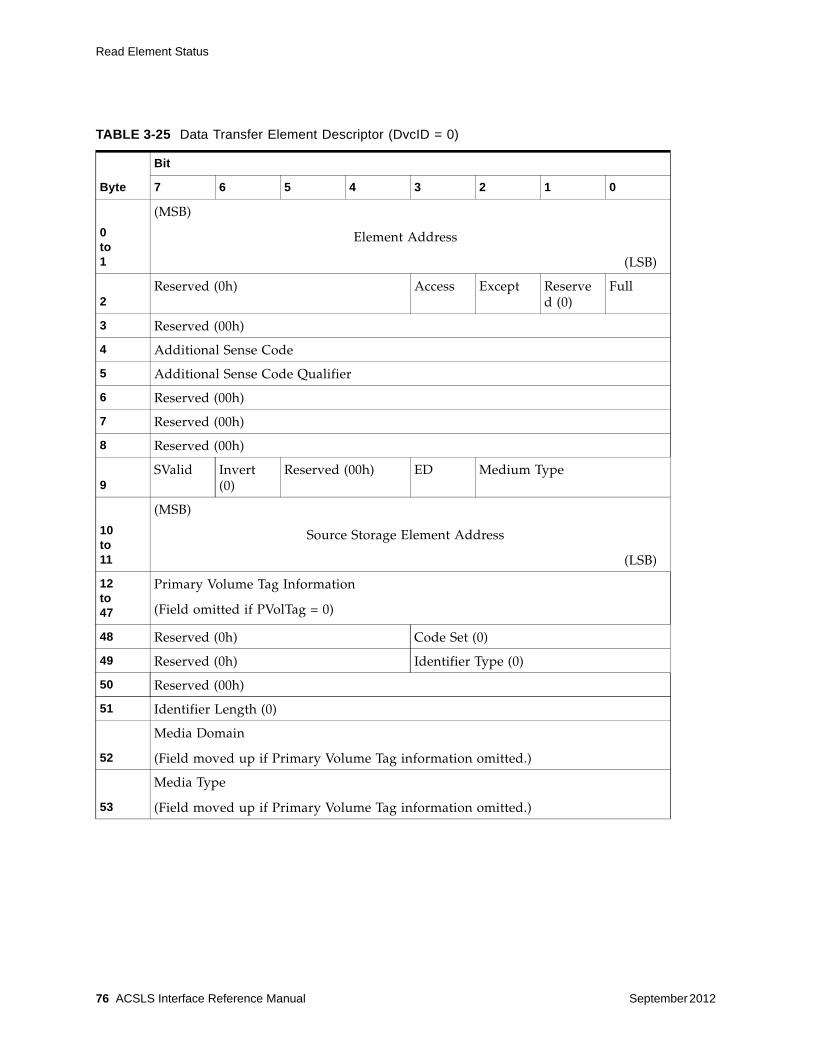
Read Element Status
76 ACSLS Interface Reference Manual September 2012
TABLE 3-25 Data Transfer Element Descriptor (DvcID = 0)
Byte
Bit
7 6 5 4 3 2 1 0
0 to 1
(MSB)
Element Address
(LSB)
2Reserved (0h) Access Except Reserve
d (0)Full
3 Reserved (00h)
4 Additional Sense Code
5 Additional Sense Code Qualifier
6 Reserved (00h)
7 Reserved (00h)
8 Reserved (00h)
9SValid Invert
(0)Reserved (00h) ED Medium Type
10to11
(MSB)
Source Storage Element Address
(LSB)
12to47
Primary Volume Tag Information
(Field omitted if PVolTag = 0)
48 Reserved (0h) Code Set (0)
49 Reserved (0h) Identifier Type (0)
50 Reserved (00h)
51 Identifier Length (0)
52
Media Domain
(Field moved up if Primary Volume Tag information omitted.)
53
Media Type
(Field moved up if Primary Volume Tag information omitted.)

Read Element Status
September 2012 SCSI Commands 77
54
Transport Domain
(Field moved up if Primary Volume Tag information omitted.)
55
Transport Type
(Field moved up if Primary Volume Tag information omitted.)
56 to87
(MSB)
Transport Serial Number
(LSB)
TABLE 3-25 Data Transfer Element Descriptor (DvcID = 0) (Continued)
Data Transfer Element Descriptor (DvcID = 0) Definitions:
Element Address This bit contains the element address of the data transfer element reported.
Access This bit indicates access is allowed to the data transfer element by the hand:
0 = Access is not allowed to the tape drive element by the hand. This will be the case when a cartridge tape is loaded and in use by the tape drive. The tape must be ejected before it becomes accessible. Access is 0 (zero) if the ED bit is 1.
1 = The tape drive is accessible.
Except This bit indicates the operational state of the data transfer element:
0 = The data transfer element is in the normal state.
1 = The data transfer element is in an abnormal state, and the Additional Sense Code and the Additional Sense Code Qualifier fields contain information regarding the abnormal state. Other fields in this descriptor might be invalid, and should be ignored.
Full This bit indicates if the data transfer element contains a cartridge tape:
0 = The data transfer element does not contain a cartridge tape.
1 = The data transfer element does contain a cartridge tape.
Additional Sense Code
This field is valid only if the Except bit is set. In the case of an exception, it contains an ASC as defined for Request Sense data.
Additional Sense Code Qualifier
This field is valid only if the Except bit is set. In the case of an exception, it contains an ASCQ as defined for Request Sense data.
SValid This bit indicates if the Source Element Address and Invert fields are valid:
0 = The Source Element Address and Invert fields are not valid.
1 = The Source Element Address and Invert fields are valid.
Invert The library does not support multi-sided media and returns a value of 0.

Read Element Status
78 ACSLS Interface Reference Manual September 2012
ED 0 = The element is enabled
1 = The element is disabled. This is set if no drive is currently assigned to the Element. It this bit is set, the Access bit is set to 0.
Medium Type This field provides the type of medium currently present in the element as determined by the medium changer.
The library returns the following values:
0h = Unspecified - the medium changer cannot determine the medium type.
1h = Data Medium
2h = Cleaning Medium
Source Storage Element Address
This field is valid only if the SValid bit is 1. It contains the address of the last element from which the data cartridge was moved.
Primary Volume Tag Information
When the PVolTag bit is set to 1, This field can be presented in one of the formats as described under the VolTag description in the Read Element Status Command.
Code Set This field specifies the code set used for the identifier field and is set to 0 (not supported) for the Data Transfer Element Descriptor (DvcID = 0):
0h = Reserved
Identifier Type The Identifier Type field indicates the format and assignment authority for the identifier and is set to 0 (not supported) for the Data Transfer Element Descriptor (DvcID = 0):
0h = Vendor Specific
Identifier Length This field indicates the length of the Identifier field and is set to 0 (not supported) for the Data Transfer Element Descriptor (DvcID = 0)
Note that the combined length of the identifier field and the Identifier Pad is 32 bytes.
Media Domain The Media Domain field along with the Media Type field provides a hierarchy of information that indicates the type of media in the element. The possible values for the Media Domain and Media Type fields are documented in “Tape Drives and Media Types” on page 95.
Note – This field is not valid if the Full bit is not set.
Media Type The Media Type field along with the Media Domain field provides a hierarchy of information that indicates the type of media in the element. The possible values for the Media Domain and Media Type fields are documented in “Tape Drives and Media Types” on page 95.
Note – This field is not valid if the Full bit is not set.

Read Element Status
September 2012 SCSI Commands 79
Data Transfer Element Descriptor Definitions (DvcID = 1)
Data transfer elements are the tape drives in the library. The Data Transfer Element Descriptor Definitions page describes a tape drive. The following table (see TABLE 3-26) shows the data returned when the DvcID bit in the command is set to 1.
Transport Domain The Transport Domain field with the Transport Type field provide a hierarchy of information that indicates the type of data transfer element installed. The possible values for the Transport Domain and Transport Type fields are documented in “Tape Drives and Media Types” on page 95.
Transport Type If the Transport Domain field is 01h, the value in the Transport Type field indicates that the drive installed. The possible values for the Transport Domain and Transport Type fields are documented in “Tape Drives and Media Types” on page 95.
Transport Serial Number
Thirty-two ASCII characters represent the unique transport serial number. For tape drives with less than 32 bytes of ASCII serial number data, the value is left-justified and the unused LSB bytes contain ASCII blanks. If the serial number is not available from a tape drive that should support an ASCII serial number, ASCII blanks are returned.
Note – Left justification in this 32-byte field provides space for serial numbers of varying lengths.
TABLE 3-26 Data Transfer Element Descriptor (DvcID = 1)
Byte
Bit
7 6 5 4 3 2 1 0
0 to 1
(MSB)
Element Address
(LSB)
2Reserved (0) Access Except RSVD
(00h)Full
3 Reserved (00h)
4 Additional Sense Code
5 Additional Sense Code Qualifier
6 Reserved (00h)
7 Reserved (00h)
8 Reserved (00h)
9SValid Invert
(0)Reserved (00h) ED Medium Type

Read Element Status
80 ACSLS Interface Reference Manual September 2012
10 to 11
(MSB)
Source Storage Element Address
(LSB)
12 to 47
Primary Volume Tag Information
(Field omitted if PVolTag = 0)
48 Reserved (0h) Code Set (2)
49 Reserved (0h) Identifier Type (1)
50 Reserved (00h)
51 Identifier Length (x)
52 to 52+x-1 (x bytes)
Identifier
32-x bytes Identifier Pad
84 Media Domain
85 Media Type
86 Transport Domain
87 Transport Type
TABLE 3-26 Data Transfer Element Descriptor (DvcID = 1)
Data Transfer Element Descriptor (DvcID = 1) Definitions:
Element Address This bit contains the element address of the data transfer element reported.
Access This bit indicates access is allowed to the data transfer element by the hand:
0 = Access is not allowed to the tape drive element by the hand. This will be the case when a cartridge tape is loaded and in use by the tape drive. The tape must be ejected before it becomes accessible. Access is 0 (zero) if the ED bit is 1.
1 = The tape drive is accessible.
Except This bit indicates the operational state of the data transfer element:
0 = The data transfer element is in the normal state.
1 = The data transfer element is in an abnormal state, and the Additional Sense Code and the Additional Sense Code Qualifier fields contain information regarding the abnormal state. Other fields in this descriptor might be invalid, and should be ignored

Read Element Status
September 2012 SCSI Commands 81
Full This bit indicates if the data transfer element contains a cartridge tape:
0 = The data transfer element does not contain a cartridge tape.
1 = The data transfer element does contain a cartridge tape.
Additional Sense Code
This field is valid only if the Except bit is set. In the case of an exception, it contains an ASC as defined for Request Sense data.
Additional Sense Code Qualifier
This field is valid only if the Except bit is set. In the case of an exception, it contains an ASCQ as defined for Request Sense data.
SValid This bit indicates if the Source Element Address and Invert fields are valid:
0 = The Source Element Address and Invert fields are not valid.
1 = The Source Element Address and Invert fields are valid.
Invert The library does not support multi-sided media and returns a value of 0.
ED 0 = The element is enabled (for example a magazine or drive has been installed or has been logically enabled)
1 = The element is disabled. This is set if no drive is currently assigned to the element. If this bit is set, the Access bit is set to 0.
Medium Type This field provides the type of medium currently present in the element as determined by the medium changer.
The library returns the following values:
0h = Unspecified - the medium changer cannot determine the medium type.
1h = Data Medium
2h = Cleaning Medium
Source Storage Element Address
This field is valid only if the SValid bit is 1. It contains the address of the last element from which the data cartridge was moved.
Primary Volume Tag Information
When the PVolTag bit is set to 1, this field can be presented in one of the formats as described under the VolTag description in the Read Element Status Command.
Code Set This field specifies the code set used for the identifier field:
2h = The identifier contains ASCII graphic codes (code values 20h through 7Eh).
Identifier Type The Identifier Type field indicates the format and assignment authority for the identifier:
0h = No assignment authority was used, and consequently there is no guarantee that the identifier is globally unique. In other words, the identifier is vendor specific.
Identifier Length This field indicates the length of the Identifier field. Note that the combined length of the Identifier field and the Identifier Pad is 32 bytes.

Release (6)
82 ACSLS Interface Reference Manual September 2012
Release (6)This command is not supported.
Release (10)This command is not supported.
Report LUNSThe Report LUNS command (A0) returns to the initiator the known LUNs to which the initiator can send commands. Each LUN returned represents a logical library. Only LUN 0 is supported in the library (see Table 3-27).
Identifier This field contains the device identification of the type indicated in the Identifier Type field and in the format specified in the Code Set field.
Identifier Pad This field contains binary zeros if the identifier is binary. This field contains ASCII blanks if the identifier is ASCII. The number of zeros or blanks depends on the length of the Identifier field. Note that the combined length of the Identifier field and the Identifier Pad is 32 bytes.
Media Domain The Media Domain field along with the Media Type field provides a hierarchy of information that indicates the type of media in the element. The possible values for the Media Domain and Media Type fields are documented in “Tape Drives and Media Types” on page 95.
Note – This field is not valid if the Full bit is not set
Media Type The Media Type field, along with the Media Domain field, provides a hierarchy of information that indicates the type of media in the element. The possible values for the Media Domain and Media Type fields are documented in “Tape Drives and Media Types” on page 95.
Note – This field is not valid if the Full bit is not set.
Transport Domain The Transport Domain field with the Transport Type field provide a hierarchy of information that indicates the type of data transfer element installed. The possible values for the Transport Domain and Transport Type fields are documented in “Tape Drives and Media Types” on page 95.
Transport Type If the Transport Domain field is 01h, the value in the Transport Type field indicates that the drive installed. The possible values for the Transport Domain and Transport Type fields are documented in “Tape Drives and Media Types” on page 95.

Report LUNS
September 2012 SCSI Commands 83
TABLE 3-27 Report LUNs command
Byte
Bit
7 6 5 4 3 2 1 0
0 Operation Code (A0h)
1 Reserved (0h)
2 Select Report
3to5 Reserved (0h)
6 to 9
(MSB)
Allocation Length
(LSB)
10 Reserved (00h)
11 Control Byte (00h)
Report LUNs command Definitions:
Allocation Length This field specifies the number of bytes that the initiator has allocated for data to be returned from the Report LUNs command.
The Allocation must be at least 16 bytes. If it is less, a check condition is returned with the sense key set to illegal request and the additional sense data set to invalid field in the command descriptor block (CDB).
Select Report This field specifies the type of logical unit addresses that shall be reported.
00h = The LUN addresses reported shall be limited to the following addressing methods: ■ LUN addressing method;■ Peripheral device addressing method; and■ Flat space addressing method.
02h = All LUNS accessible to the initiator for this port are accessible

Report LUNS
84 ACSLS Interface Reference Manual September 2012
Report LUNs Data Definition
The target device returns the following data for the Report LUNs command (see Table 3-28).
TABLE 3-28 Report LUNs Data Definition
Byte Bit
7 6 5 4 3 2 1 0
0
to
3
(MSB)
LUN list length (n-7)
(LSB)
4
to
7Reserved (0)
8
to
15First LUN
.
.
.
n-7
to
nLast LUN
Report LUNs Data Definitions:
LUN list length The target device returns a LUN list length of n-7. Each LUN returned represents a logical library. If no logical libraries have been mapped for the requesting initiator, LUN 0 is still returned.

Request Sense
September 2012 SCSI Commands 85
Request Sense The Request Sense command (03) requests the library transfer sense data to the initiator (seeTable 3-29).
Logical libraries use an FC-2 conforming transport that provides autosense. This means that sense data for a failed command is always returned with a Check Condition status in the command response and is never saved by the target. Therefore, Request Sense will always return Sense Data with a Sense Key set to No Sense and ASC/ASCQ fields set to 0.
However, all Sense Keys and associated ASC/ASCQ fields that can be returned by other commands are documented here
.
TABLE 3-29 Request Sense Command
Byte
Bit
7 6 5 4 3 2 1 0
0 Operation Code (03h)
1Reserved (00h) Desc
(0h)
2 Reserved (00h)
3 Reserved (00h)
4 Allocation Length
5 Control Byte (00h)
Request Sense Command Definitions:
Desc The Desc bit indicates which sense data format shall be returned.
The library returns a value of 0, indicating fixed format sense data is returned.
Allocation Length This field specifies the number of bytes that the initiator has allocated for returned sense data. The library provides a maximum of 14h (20d) bytes of sense data.

Request Sense
86 ACSLS Interface Reference Manual September 2012
Sense Data
• If the Request Sense command was issued to an unsupported LUN. In this case, the library does not return a check condition and returns sense data:
■ Sense Key set to Illegal Request (05h)■ ASC set to Logical Unit Not Supported (25h)■ ASCQ set to 00h
If no sense data is available for the specified I_T_L nexus (this is always the case for a logical library), the library returns sense data:
■ Sense Key set to No Sense (0h)■ ASC set to No Additional Sense Information (00h)■ ASCQ set to 00h
The library returns Check Condition status for a Request Sense command only to report errors specific to the command itself.
For example:■ A non-zero reserved bit is detected in the CDB.■ An unrecoverable parity error is detected on the data bus.

Request Sense
September 2012 SCSI Commands 87
Request Sense Data Definitions
Table 3-30 shows the Request Sense Data Definitions.
TABLE 3-30 Request Sense Data
Byte
Bit
7 6 5 4 3 2 1 0
0Valid (0)
Error Code (70h)
1 Segment Number (00h)
2 Reserved (0) Sense Key
3 to 6
(MSB)
Information (00h, 00h, 00h, 00h)
(LSB)
7 Additional Sense Length (n-7)
8 to 11
(MSB)
Command Specific Information (00h, 00h, 00h, 00h)
(LSB)
12 Additional Sense Code
13 Additional Sense Code Qualifier
14 Field Replaceable Unit Code (00h)
15 SKSV C/D Reserved (0) BPV (0) Bit Pointer (0h)
16 to 17
(MSB)
Field Pointer
(LSB)
18 Reserved (0)
19 Reserved (00h)

Request Sense
88 ACSLS Interface Reference Manual September 2012
Request Sense Data Definitions:
Valid This bit indicates if the Information field contains valid data. The library does not return data in the Information field. The value is 0.
Error Code This bit indicates if the error is current or deferred. The library returns only current errors. The value is 70h.
Segment Number The library does not support segment numbers and returns a value of 00h.
Sense Key The Sense Key (SK) field, with the Additional Sense Code and Additional Sense Code Qualifier fields, describes the error.
Information The library does not support this field and returns a value of 00h.
Additional Sense Length
This field indicates the Additional Sense Length provided by the library excluding this byte. The typical value is 0Ch (12d).
Command Specific Information
The library does not support this field and returns a value of 00h.
Additional Sense Code
The Additional Sense Code (ASC) field, with the Sense Key and Additional Sense Code Qualifier fields, describes the error.
Additional Sense Code Qualifier
The Additional Sense Code Qualifier (ASCQ) field, with the Sense Key and Additional Sense Code fields, describes the error.
Field Replaceable Unit Code
The library does not support this field and returns a value of 00h.
SKSV (Sense Key Specific Valid)
When the Sense Key Specific Valid bit is set to 1, the fields C/D and Field pointer are valid. Otherwise, ignore these fields.
C/D (Command/Data)
Command/Data indicates whether the Check Condition status resulted from an illegal parameter in either the command descriptor block (Command) or the parameter list (Data)
0 = Illegal parameter in the parameter list.
1 = Illegal parameter in the command descriptor block.
BPV (Bit Pointer Valid)
The library does not support the Bit Pointer Valid (BPV) field and returns a value of 0.
Bit Pointer The library does not support this field and returns a value of 0h.
Field Pointer This field contains the number of the byte where the error occurred. Byte numbers start at 00. When a multiple-byte field is in error, the Field Pointer contains the value of the most significant byte of the field, which is the byte with the lowest byte number. For example, if a field consists of bytes 02, 03, and 04, the most significant byte is 02.

Request Sense
September 2012 SCSI Commands 89
Sense Key
The Sense Key field provides basic information about an error. Table 3-31 lists the Sense Keys with an explanation for each code. The Sense Key field, with the Additional Sense Code and Additional Sense Code Qualifier fields, provides a description about the error.
See “Additional Sense Codes and Qualifiers” on page 89 for more information.
TABLE 3-31 Sense Key Code Descriptions
Additional Sense Codes and Qualifiers
Bytes 12 and 13 of the sense data contain the Additional Sense Code (ASC) and Additional Sense Code Qualifier (ASCQ) fields. These codes provide additional device- specific information about the error or exception.
Each code contains a unique combination of the sense key, additional sense code, and additional sense code qualifier. The following pages describe the error codes for the library grouped by type of sense key.
No Sense Key
The library returns a No Sense Key (00h) when sense is requested, but no error has occurred. The ASC and ASCQ values are zero.
Code Error Description
0h No Sense Indicates there is no specific sense key information to be reported. A sense key of 0 indicates a successful command.
2h Not Ready Indicates the addressed logical unit is not ready for library motion commands (library is not initialized, device is not ready).
4h Hardware Error Indicates the device detected an unrecoverable hardware failure while performing the command or during a self-test.
5h Illegal Request Indicates an illegal parameter in the command descriptor block or in the parameter list data.
6h Unit Attention Indicates a power-on or reset has occurred to the device, or a not ready-to-ready transition has occurred, or an I/O element has been accessed. Also, this may indicate mode parameters have changed, or the microcode has been changed.
Bh Aborted Command Indicates the device aborted the command. The initiator might be able to recover by trying the command again.

Request Sense
90 ACSLS Interface Reference Manual September 2012
Not Ready Sense Key Codes
TABLE 3-32 Not Ready Sense Keys
If a command is sent when the library is not ready, it generates a Not Ready error code (see Table 3-32). The following code describe the conditions of the library that can generate Not Ready codes.
Hardware Error Sense Key
TABLE 3-33 Hardware Error Sense Keys
The library generates a Hardware Error sense key (see Table 3-33) if a hardware or firmware error is detected during command execution. The following pages describe the conditions that generate hardware errors.
Description Sense Key ASC ASCQ
Not Ready, Maintenance Mode 2h 04h 81h
Not Ready Sense Key Code Definitions:
Not Ready, Maintenance Mode
The logical library is offline.
Description Sense Key ASC ASCQ
Hardware Error, Tape Drive 4h 40h 02h
Hardware Error, Internal Target Failure 4h 44h 00h
Hardware Error Sense Key Definitions:
Hardware Error, Tape Drive
The library generates a tape-drive error when an operation to the drive fails. The problem could be the tape drive or the interface between the library and tape drive.
Hardware Error, Internal Target Failure
The library generates a hardware error when an unexpected condition is detected by ACSLS software that controls the SCSI interface. This error is used for arbitrary limitations of the software.

Request Sense
September 2012 SCSI Commands 91
Illegal Request Sense Key
TABLE 3-34 Illegal Request Sense Keys
Any illegal parameters in a command descriptor block (CDB) or parameter list for a particular command generate an Illegal Request sense key (see TABLE 3-34).
In some cases, additional information is available in Byte 15 of the sense data, which includes the sense-key-specific-value (SKSV) and command/data (C/D) fields. This information indicates the byte in the command descriptor block or the parameter list, which is in error.
If available, the SKSV bit in the sense data is set to 1. See “Request Sense” on page 85 for more information.
Unit Attention Sense Key
TABLE 3-35 Unit Attention Sense Keys
The library generates a Unit Attention sense key (see Table 3-35) for all initiators if the library needs to inform the host of an asynchronous event. The following pages describe library conditions that generate Unit Attention errors.
Sense Key ASC ASCQ SKSV
Invalid Command Operation Code 5h 20h 00h Yes
Invalid Element Address 5h 21h 01h Yes
Invalid Field in CDB 5h 24h 00h Yes
Logical Unit Not Supported 5h 25h 00h No
Incompatible Medium 5h 30h 00h No
Saving Parameters Not Supported 5h 39h 00h Yes
Medium Not Present, Drive Not Unloaded 5h 3Ah 00h No
Destination Element Full 5h 3Bh 0Dh No
Source Element Empty 5h 3Bh 0Eh No
Description Sense Key ASC ASCQ
Not Ready-to-Ready Transition 6h 28h 00h
CAP Element Accessed 6h 28h 01h
Mode Parameters Changed 6h 2Ah 01h
Reservations Preempted 6h 2Ah 03h
Reservations Released 6h 2Ah 04h
Registrations Preempted 6h 2Ah 05h
LUN Data Has Changed 6h 3Fh 0Eh

Request Volume Element Address
92 ACSLS Interface Reference Manual September 2012
Aborted Command Sense Key
TABLE 3-36 Aborted Command Sense Keys
Command Overlap
The library detected another command from an initiator while one was already in process.
Request Volume Element AddressThis command is not supported.
Unit Attention Sense Key Definitions:
Not Ready-to-Ready Transition
The library generates this type of Unit Attention when the library transitions to a ready state from a not ready state. This transition can occur following any conditions that cause a not ready state. A Unit Attention is generated for all initiators.
CAP Element Accessed The library generates this type of Unit Attention to indicate that import/export cells have been accessed. This could be the result of a logical ENTER or EJECT operation. Issue a Read Element Status command to obtain an updated inventory. A Unit Attention is generated for all initiators.
Mode Parameters Changed
The library generates this type of Unit Attention when the administrator changes the library configuration, i.e. adds/removes logical elements, adds/removes drives, etc. This could be the result of a logical ENTER or EJECT operation. Issuing a Mode Sense command can retrieve the current parameters. This Unit Attention is issued for all initiators except the one that performed the Mode Select.
Reservations Preempted/Reservations Released/Registrations Preempted
The library generates these types of Unit Attention sense keys when one initiator has its persistent reservations or registrations cleared by another initiator.
LUN Data Has Changed
The logical library generates this type of Unit Attention when a logical library has been added or removed.
Description Sense Key ASC ASCQ
Command Overlap 0Bh 4Eh 00h

Reserve (6)
September 2012 SCSI Commands 93
Reserve (6)This command is not supported.
Reserve (10)This command is not supported.
Send DiagnosticThis command is not supported.
Send Volume Tag This command is not supported.
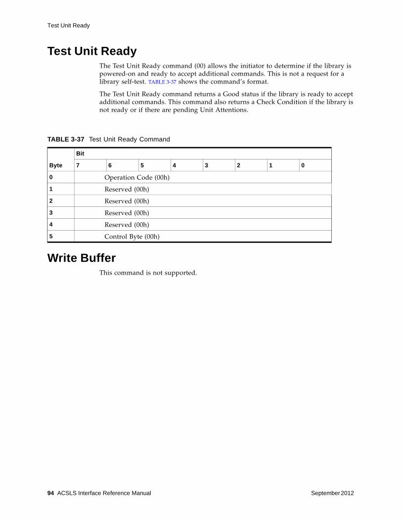
Test Unit Ready
94 ACSLS Interface Reference Manual September 2012
Test Unit Ready The Test Unit Ready command (00) allows the initiator to determine if the library is powered-on and ready to accept additional commands. This is not a request for a library self-test. TABLE 3-37 shows the command’s format.
The Test Unit Ready command returns a Good status if the library is ready to accept additional commands. This command also returns a Check Condition if the library is not ready or if there are pending Unit Attentions.
Write BufferThis command is not supported.
TABLE 3-37 Test Unit Ready Command
Byte
Bit
7 6 5 4 3 2 1 0
0 Operation Code (00h)
1 Reserved (00h)
2 Reserved (00h)
3 Reserved (00h)
4 Reserved (00h)
5 Control Byte (00h)

September 2012 Tape Drives and Media Types 95
A
Tape Drives and Media Types
For a list of tape drives and tape media supported, as well as tape drive and media compatibility, see the ACSLS 8.1 Product Information Guide.

96 ACSLS Interface Reference Manual September 2012

September 2012 Glossary 97
Glossary
This glossary defines terms and abbreviations in this and other product related publications.
Numerics2NA PDU that supplies power to the redundant AC power grid and the third and fourth accessory racks. See also N+1.
A access doorA door on either side of the front facade through which service personnel can enter the library. Optional CAPs are attached to the right access door.
accessory rackAn area of the drive and electronics module that is used for Product Name library electronic and power equipment and for other standard 19-inch rack-mount electronic equipment. Up to four racks are permitted in the electronics/drive assembly. Rack-mount equipment must be on the approved equipment list.
arrayA partitioned unit that holds multiple objects, such as cartridges or tape drive tray assemblies.
asynchronous (ASYNC)Not synchronized; not occurring at regular, predetermined intervals. Asynchronous transmissions send one data character at a time, at irregular intervals, rather than in one steady stream; a start bit and a stop bit notify the receiver when the transmission begins and ends. Contrast with synchronous.
auditSee host audit and security audit.
automation bezelA tape drive attachment with a locator target for positioning gets and puts to the tape drive.

98 ACSLS Interface Reference Manual September 2012
BbackplaneThe main circuit board inside electronic equipment that contains the central processing unit, the bus, memory sockets, expansion slots, and other components.
bar code line scan cameraA component of the robot that is used for cartridge identification and position calibration.
blind mate connectorA connector that allows hot plugging instead of manually placing a cable between two fixed connectors.
bulk loadManually loading cartridges into the library, for example, during library installation.
CCAPSee cartridge access port.
cardSynonymous with printed wire assembly.
cartridge access port (CAP)A device in the library that allows an operator to insert or remove cartridges during library operations.
Synonymous with import/export mail slot in SCSI and open system libraries.
cartridge biasLeft or right justification of a cartridge within a storage cell, CAP, or tape drive.
cartridge moverSee robot.
cartridge proximity detectorA component that determines if a cell is empty or contains an unlabeled cartridge during a label reading error recovery procedure. Synonymous with empty cell detector.
CCD(1) Charge couple device.
(2) Cell contents database.
cellThe location in the library in which a tape cartridge is stored. Synonymous with slot.
cell arrayAn array that holds multiple cartridges when not in use.
The Product Name library uses 8-cell, 13-cell, and 14-cell arrays for cartridge storage.
cleaning cartridgeA tape cartridge that contains special material to clean the tape path in a transport or drive.
CLICommand line interface.

September 2012 Glossary 99
cold swapTo remove and replace a system component (typically one such as a logic board that has no redundant backup) after system operations have been stopped and system power has been disabled. Contrast with hot swap.
CompactPCI (cPCI®)Industry standard bus used for card-to-card bus expansion.
cPCISee CompactPCI.
Ddata cartridgeA term used to distinguish a cartridge onto which a tape drive may write data from a cartridge used for cleaning or diagnostic purposes.
diagnostic cartridgeA data cartridge with a “DG” label that is used for diagnostic routines.
DLEData link escape.
drive and electronics moduleThe module in an Product Name library that houses the electronics control module, power distribution units (PDUs), power supplies, accessory racks and equipment, and tape drives for the library.
drive array assemblyAn array that is installed in the drive and electronics module for mounting tape drive tray assemblies. The drive and electronics module holds up to four array assemblies, and each array holds up to 16 tape drive tray assemblies.
drive bayA partitioned section of the tape drive array assembly that holds one tape drive tray assembly.
drop-off cellsCells used to hold a cartridge in the event of a robot failure that occurs while a cartridge is in the robot hand.
EECMSee electronics control module.
electronics control moduleThe assembly that:
• Processes commands from a host system
• Coordinates the activities of robots, elevators, pass-thru ports, and tape drives
• Monitors status inputs from sensors and switches
elevatorThe device that transports cartridges vertically, across rail boundaries.

100 ACSLS Interface Reference Manual September 2012
emergency power-off (EPO)(1) A safety scheme that allows a “power down” of a subsystem or a system as a whole instead of powering it down component-by-component.
(2) A safety switch on a machine or in a data center that allows a user to immediately power down a machine or a data center power supply by cutting off the external source power.
Enterprise Systems Connection (ESCON)(1) A set of fiber-optic based products and services developed by IBM that allows devices within a storage environment to be dynamically configured. A channel-to-control unit I/O interface that uses optical cables as a transmission medium.
environmental monitorsA collective term for the sensors that track temperatures, fan speeds, and the status of various other mechanism within a library.
EPOSee emergency power-off.
ESCONSee Enterprise Systems Connection.
EthernetA local-area, packet-switched network technology. Originally designed for coaxial cable, it is now found running over shielded, twisted-pair cable. Ethernet is a 10- or 100-megabytes-per-second LAN.
exportThe action in which the library places a cartridge into the cartridge access port so that the operator can remove the cartridge from the library. Synonymous with eject.
FfailoverThe act of moving to a secondary or redundant path when the primary path fails.
Fast LoadWith Fast Load enabled, an FC initiator that issues a mount operation receives a successful response once the operation has been validated and accepted by ACSLS, but before cartridge movement begins.
FFCFlat flexible cable.
Fibre ChannelA bidirectional, full-duplex, point-to-point, serial data channel structured for high performance capacity. The Fibre Channel is an interconnection of multiple communication ports, called N_Ports. These N_Ports are interconnected by a switching network, called a fabric, to a point-to-point link, or an arbitrated loop. Fibre Channel is a generalized transport mechanism with no protocol of its own. A Fibre Channel does not have a native input/output command set, but can transport existing Upper Level Protocols (ULP) such as SCSI and IPI. Fibre Channel operates at speeds of 100 MB per second (full speed), 50 MB per second (half speed), 25 MB (quarter speed), or 12.5 MB (eighth speed). Fibre Channel operates over distances of up to 100 m over copper media or up to 10 km over optical links.

September 2012 Glossary 101
fibre connection (FICON)An IBM S/390-based channel architecture that provides up to 256 channels in a single connection, each having a capacity of 100 MB per second.
FICONSee fibre connection.
front controller moduleThe module that houses the controller for the elevators, CAPs, turntables, and safety barrier.
front facadeThe external portion of the customer interface module, between the access doors, that holds the:
• Membrane keypad
• Product logos
• Optional touch screen operator control panel
GgetAn activity in which a robot obtains a cartridge from a cell or drive.
gripper(1) The portion of the hand assembly that grasps the cartridge.
(2) The part of the hand assembly that grasps and holds a cartridge during transport.
Hhand assemblyA part of the library robot whose function is to grasp cartridges and move them between storage cells and drives. A camera on the hand assembly reads cartridge volume labels.
See also bar code line scan camera.
HBZ moduleSee front controller module.
host auditThe process of updating the cartridge VOLIDs and locations (collected by a security audit) in a host CDS. This audit is initiated by a host command.
hot swapRemoval and replacement of a system component while system power remains on and system operations continue. Contrast with cold swap. Contrast with hot-pluggable.
Synonymous with online servicing.
hot-pluggableThe capability that allows a CSE to replace FRUs while power to the FRU is maintained. This feature allows hardware maintenance actions and hardware upgrades to proceed without disrupting subsystem availability. Contrast with hot swap.

102 ACSLS Interface Reference Manual September 2012
IimportThe process of placing a cartridge into the cartridge access port so that the library can insert it into a storage cell.
Synonymous with enter.
interlock switchA switch that disconnects power to library mechanisms, excluding tape drives, when the front door is opened.
Kkeypad interfaceSee membrane keypad.
LLibCam MonitoringA feature that provides two cameras, one for each leg of the horseshoe, for viewing activity inside the library. The touch screen operator control panel is required.
library cameraSee LibCam Monitoring.
library complex(1) Two or more Product Name libraries attached to each other with PTPs.
(2) Two Product Name libraries attached to each other with PTPs in which one library is the Master library and the other is the Standby library for pass-through purposes.
library controller (LC)The HBC card within the Product Name library that controls operations and communicates with the operator panel.
library operator panelSee touch screen operator control panel.
logical libraryAn emulation of a physical library.
Mmaster (pass-thru port)The side of a pass-thru port (PTP) that contains the electronics that control the actions of the PTP. See also standby (pass-thru port).
NN+1A PDU that provides power to the redundant AC power grid. See also 2N.

September 2012 Glossary 103
Oonline replacementReplacement or service of a module while the library remains operational. The service person may be required to power off the module before removing or replacing it. Synonymous with hot swap.
operator panel See touch screen operator control panel.
Ppass-thru port (PTP)A mechanism that enables a cartridge to pass through from one library to another in a multiple modular library system.
PCIPeripheral component interconnect.
PDUSee power distribution unit.
physical libraryA single Product Name library consisting of a customer interface module, robotics interface module, and an drive and electronics module, with one to three Storage Expansion Modules optional. See also logical library.
PLCPower line communications.
PLISee primary library interface.
power distribution unit (PDU)A device for the distribution of AC line power from one inlet to multiple outlets. Multiple PDUs provide higher availability because the power continues if one PDU (or its alternating current [AC] source if the PDUs use separate AC sources) loses power.
power gridA power circuit that minimizes power failures that cause the library to cease operations.
An Product Name library has five power grids, two for AC power and three for DC power.
power/communication bus railA rail that sits on the robot track to provide 48 VDC power and communication to the robot.
primary library interface (PLI)The communication path between the operator panel and the library controller (the HBC card.) This consists of Ethernet with TCP/IP and XML.
PTPSee pass-thru port.

104 ACSLS Interface Reference Manual September 2012
putAn activity in which a robot places a cartridge into a cell or drive.
PWAPrinted wiring assembly.
Rrail(1) That portion of the upper robot track assembly that provides power and communication to the robot.
rail assemblyThe mechanism on which the robot travels between cartridge arrays and tape drives.
reach mechanismA component of the robot that moves the gripper to get or put a cartridge at a designated location.
remote operator consoleThe customer’s operator panel that interfaces with the PLI. See also security software layer.
robotA mechanism that moves horizontally along a track in the Product Name to transport tape cartridges to and from other locations in the library. Also called an S-bot or t-bot.
robotics interface moduleThe module containing the curved rails and pass-through port (PTP) assemblies.
Ssafety barrierA motor-driven barrier that separates the service areas of the front interface assembly from the rest of the library so that service personnel can safely repair or replace failed library mechanisms while the library continues normal operations.
S-botSmall robot.
security auditThe process of reading and storing in Product Name library memory the VOLIDs and locations of all cartridges in the library. See also host audit.
security software layer (SSL)The communication path between the PLI and the remote operator console.
service areaAn area between the access doors of the customer interface module and the safety barrier in which an inoperable robot is stored for service and other mechanisms can be repaired or replaced.
SSiSystem Server infrastructure.
standby (pass-thru port)The side of a pass-thru port (PTP) that operates in response to actions initiated by the master side of the PTP. See also master (pass-thru port).

September 2012 Glossary 105
storage expansion moduleAn optional module for the Product Name library that provides up to 1728 additional cartridge storage slots. From one to three modules can be attached to each library.
Ttape cartridgeA container holding magnetic tape that can be processed without separating the tape from the container.
The library uses data, diagnostic, and cleaning cartridges. These cartridges are not interchangeable.
tape driveAn electromechanical device that moves magnetic tape and includes mechanisms for writing and reading data to and from the tape.
tape drive tray assemblyThe mechanical structure that houses a tape drive, fan assembly, power and logic cards, cables, and connectors for data and logic cables. Synonymous with drive tray assembly.
tape storage areaThe area in the Product Name library where cartridges are stored.
tape transport interface (TTI)An interface to control/monitor tape movement.
t-botTall robot.
touch screen operator control panelAn optional feature consisting of a flat-panel display with a touch screen interface and a panel mount computer. This feature is attached to the front facade.
trackThe horizontal path upon which a robot travels.
track drive mechanismThe component that moves the robot along the track between the cell arrays, CAPs, and tape drives.
TTISee tape transport interface.
turntableA mechanism that transfers cartridges between the aisles within a single library.
UUA standard unit of measurement of vertical space inside a rack-mount cabinet equal to 44.5 mm (1.75 in.).

106 ACSLS Interface Reference Manual September 2012
UARTUniversal asynchronous receiver/transmitter.
Vvacancy plateA plate that covers an unused bay, such as a drive bay or power supply bay.
WwristA mechanism in the robot assembly that allows the robot to access the outer and inner storage walls.

September 2012 Index 107
Index
A
about the interface 15ACSLS 8.1 Graphical User Interface 21ACSLS 8.1 Logical Library 21ACSLS 8.1 system 21
B
benefits of SCSI 17
C
CDBs 32command
control byte 34command descriptor blocks 32configurations, SCSI 16control byte 34
D
Data Transfer Element Descriptor Definitions page 75, 79
Data transfer elements 75, 79Device Capabilities page 51Drive Elements 25
E
Element Address Assignment page 49
F
FC-PH 18Fibre Channel Physical and Signaling Interface 18Fibre Channel Standard 18flag bit, control byte 34format
control byte 34
G
GBIC 19glossary 97
H
Hand Element 22
I
implementation of SCSI 17Import/Export elements 73import/export elements 22Initiator 15Inquiry command 27, 37
L
linkbit, control byte 34
logical unit numbers 16logical units 16LUN masking 21, 28LUNs 16, 21LUNs command 28
M
Mode Sense (6) command 27, 45Mode Sense Device Capabilities Page 23Move Medium command 22, 55Move Medium commands 27
P
Peer-to-peer interface communication 15Position to Element command 56Prevent/Allow Medium Removal command 23, 58PTP-CMC bit 74
R
Read Element Status command 59, 64Report LUNS command 82Request Sense command 85, 86Reserve and Release commands 28

108 ACSLS Interface Reference Manual September 2012
S
SCSIbenefits 17implementation 17overview 15
SCSI bus 15Implementation 17
SCSI Media Changer 21small computer system interface 15SMC 21Storage elements 70storage elements 23
T
Target 15Test Unit Ready command 94
V
Volumes 22