Embed Size (px)
Citation preview
66 Davis Hill Road, Weston, CT 06883 USATel: (203) 454-0704 • Fax: (203) 454-0706
E-mail: [email protected] Web: stokesengineering.com
SEC7/30/091
Stokes Engineering Company, LLC
July 30, 2009
Joseph McCarthyDirector (Projects)Perdaman Chemicals and Fertilisers Pty. Ltd.Level 4, 172 St. Georges TerracePerth, WA 6000
Dear Joe,
Following is the July 30 report.
Best Regards,
Keith J. Stokes
Stokes Engineering Company
SEC7/30/092
Review of the Technology Selections
for
Perdaman Chemical and Fertilisers Pty., Ltd.
By
Stokes Engineering Company
July 30, 2009
Stokes Engineering Company
SEC7/30/093
Contents
Page
1.0 Scope of Work 4
2.0 Introduction 4
3.0 Summary and Conclusions 4
4.0 Ammonia Technology 5 4.1 Experience 5 4.2 Efficiency 5 4.3 Emissions 5
5.0 Urea Technology 6 5.1 Experience 6
5.2 Efficiency 6 5.3 Emissions 8
6.0 Stokes’ Résumé and Publications and SEC’s Job List 9
Stokes Engineering Company
SEC7/30/094
1.0 Scope of Work
Perdaman Chemicals and Fertilizers (PCF) asked Stokes Engineering Company to review its ammoniasynthesis, urea synthesis, and urea granulation technology selections in terms of experience, efficiency,and emissions compared with the best available technologies.
2.0 Introduction
PCF’s technology selections are:Process Licensor
Ammonia Synthesis Topsøe Urea Synthesis Stamicarbon
Urea Granulation Stamicarbon
PCF’s project will include the world’s largest single-train ammonia synthesis section (synloop). Topsøe’sdesign package will include the ammonia converter, syngas compressor, refrigeration compressor, heatexchangers, knock-out drums, pumps, and piping specifications. Topsøe is a top ammonia processlicensor. On the urea side, PCF’s project will include two Stamicarbon urea synthesis trains and twogranulation trains. Stamicarbon has the world’s best urea technology. It has been the leading technicalinnovator since 1954.
3.0 Summary and Conclusions
Ammonia SynthesisTopsøe can achieve 3,500 mtd using equipment that has been field-proven at effectively the requiredprocess duty. Topsøe’s synloop energy efficiency equals or exceeds the industry standard. Its synloopemissions will be negligible except during plant startups and plant upsets. All pressure safety valves andvents exhaust to a flare.
Urea SynthesisStamicarbon’s Urea2000plus Pool Condenser technology is proven. Its energy efficiency and emissionsare the best in the industry.
Urea GranulationStamicarbon’s urea granulation technology is proven. Its energy efficiency and emissions equal or exceedthe best in the industry.
Stokes Engineering Company
SEC7/30/095
4.0 Ammonia Technology
4.1 Experience PCF has selected a Topsøe 3,500 mtd single-train synthesis loop.
Siuci, at 2,000 mtd, is Topsøe’s largest onstream reference plant to date. It started up this year in Sohar, Oman.
Engro in Pakistan, at 2,200 mtd, is Topsøe’s largest plant presently under construction. It should start up next year.
Qafco in Qatar, at 2,200 mtd x 2, is also under construction and should start up in 2011.
Siuci, Engro, and Qafco are natural-gas-based plants. PCF’s gasification-based plant will have a lower inerts level in the synloop. Also, Topsøe plans to raise PCF’s synloop operating pressure to achieve 3,500 mtd.
4.2 Efficiency Topsøe’s synthesis loop energy efficiency equals the best available for magnetite catalyst and synloops of comparable investment cost.
4.3 Emissions PCF’s ammonia plant will be designed to U.S. and European standards and its emissions will be as low as the best technology can ensure.
Continuous Emissions A header system will route all emissions to a flare. The emissions of consequence are hydrogen and ammonia. The flare will combust them.
The syngas and refrigeration compressors’ dry-gas seals release small amounts of gas. The compressor vendors will make the expected flow rates available later in the project.
Intermittent Emissions Syngas is vented to flare during transient conditions. PCF might need to depressure the synloop to safeguard against fire or before doing maintenance work. Depressuring flows should not exceed 75,000 Nm3/h and might take 15 to 30 minutes every two years. PCF may route the synloop gas to an offsite syngas header.
Refrigerant. PCF may choose to empty the circuit of 600 Nm3 of ammonia every five years.
Stokes Engineering Company
SEC7/30/096
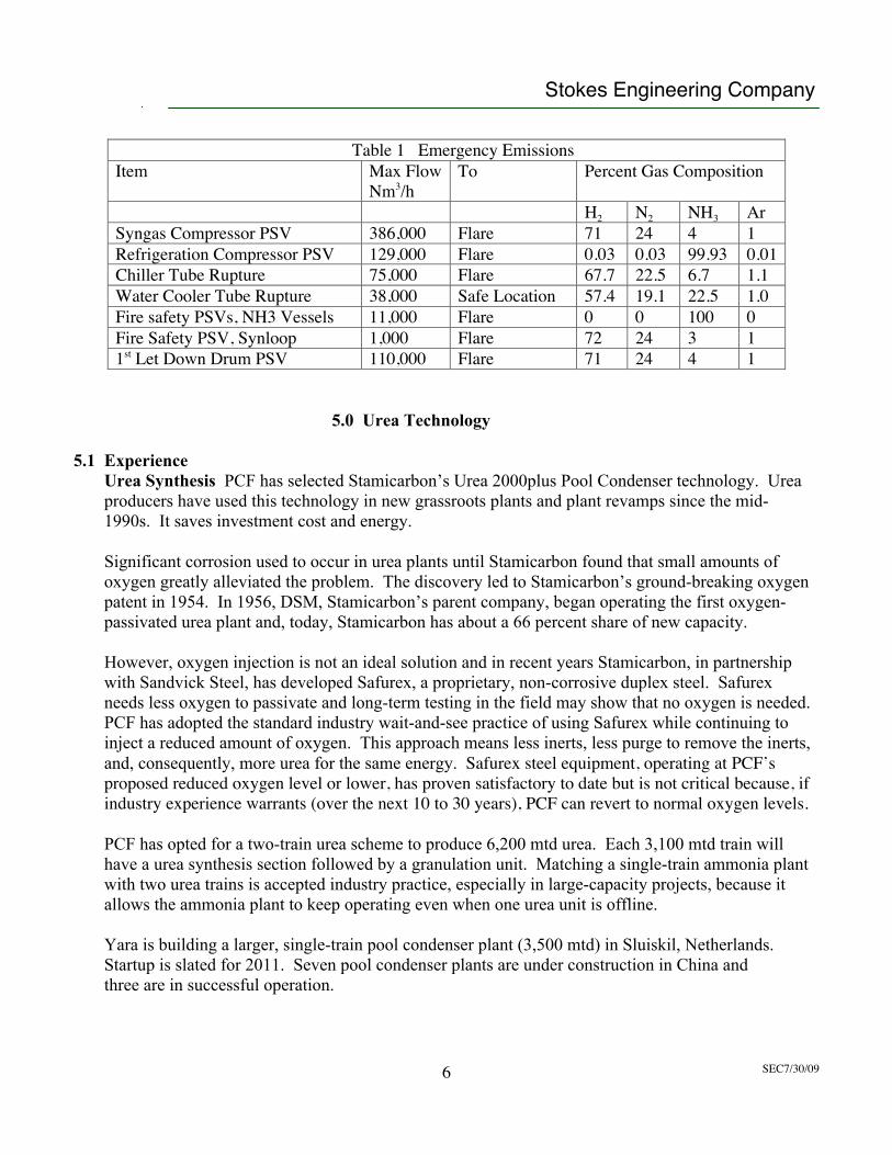
Table 1 Emergency EmissionsItem Max Flow
Nm3/hTo Percent Gas Composition
H2 N2 NH3 ArSyngas Compressor PSV 386,000 Flare 71 24 4 1Refrigeration Compressor PSV 129,000 Flare 0.03 0.03 99.93 0.01Chiller Tube Rupture 75,000 Flare 67.7 22.5 6.7 1.1Water Cooler Tube Rupture 38,000 Safe Location 57.4 19.1 22.5 1.0Fire safety PSVs, NH3 Vessels 11,000 Flare 0 0 100 0Fire Safety PSV, Synloop 1,000 Flare 72 24 3 11st Let Down Drum PSV 110,000 Flare 71 24 4 1
5.0 Urea Technology
5.1 Experience Urea Synthesis PCF has selected Stamicarbon’s Urea 2000plus Pool Condenser technology. Urea producers have used this technology in new grassroots plants and plant revamps since the mid- 1990s. It saves investment cost and energy.
Significant corrosion used to occur in urea plants until Stamicarbon found that small amounts of oxygen greatly alleviated the problem. The discovery led to Stamicarbon’s ground-breaking oxygen patent in 1954. In 1956, DSM, Stamicarbon’s parent company, began operating the first oxygen- passivated urea plant and, today, Stamicarbon has about a 66 percent share of new capacity.
However, oxygen injection is not an ideal solution and in recent years Stamicarbon, in partnership with Sandvick Steel, has developed Safurex, a proprietary, non-corrosive duplex steel. Safurex needs less oxygen to passivate and long-term testing in the field may show that no oxygen is needed. PCF has adopted the standard industry wait-and-see practice of using Safurex while continuing to inject a reduced amount of oxygen. This approach means less inerts, less purge to remove the inerts, and, consequently, more urea for the same energy. Safurex steel equipment, operating at PCF’s proposed reduced oxygen level or lower, has proven satisfactory to date but is not critical because, if industry experience warrants (over the next 10 to 30 years), PCF can revert to normal oxygen levels.
PCF has opted for a two-train urea scheme to produce 6,200 mtd urea. Each 3,100 mtd train will have a urea synthesis section followed by a granulation unit. Matching a single-train ammonia plant with two urea trains is accepted industry practice, especially in large-capacity projects, because it allows the ammonia plant to keep operating even when one urea unit is offline.
Yara is building a larger, single-train pool condenser plant (3,500 mtd) in Sluiskil, Netherlands. Startup is slated for 2011. Seven pool condenser plants are under construction in China and three are in successful operation.
Stokes Engineering Company
SEC7/30/097
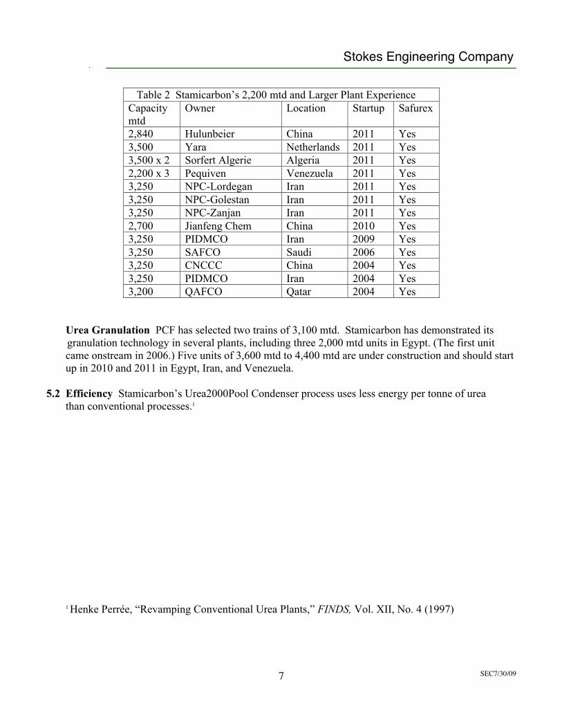
Table 2 Stamicarbon’s 2,200 mtd and Larger Plant ExperienceCapacitymtd
Owner Location Startup Safurex
2,840 Hulunbeier China 2011 Yes3,500 Yara Netherlands 2011 Yes3,500 x 2 Sorfert Algerie Algeria 2011 Yes2,200 x 3 Pequiven Venezuela 2011 Yes3,250 NPC-Lordegan Iran 2011 Yes3,250 NPC-Golestan Iran 2011 Yes3,250 NPC-Zanjan Iran 2011 Yes2,700 Jianfeng Chem China 2010 Yes3,250 PIDMCO Iran 2009 Yes3,250 SAFCO Saudi 2006 Yes3,250 CNCCC China 2004 Yes3,250 PIDMCO Iran 2004 Yes3,200 QAFCO Qatar 2004 Yes
Urea Granulation PCF has selected two trains of 3,100 mtd. Stamicarbon has demonstrated its granulation technology in several plants, including three 2,000 mtd units in Egypt. (The first unit came onstream in 2006.) Five units of 3,600 mtd to 4,400 mtd are under construction and should start up in 2010 and 2011 in Egypt, Iran, and Venezuela.
5.2 Efficiency Stamicarbon’s Urea2000Pool Condenser process uses less energy per tonne of urea than conventional processes.1
1 Henke Perrée, “Revamping Conventional Urea Plants,” FINDS, Vol. XII, No. 4 (1997)
Stokes Engineering Company
SEC7/30/098
5.3 Emissions PCF’s urea plant will be designed to U.S. and European standards and its emissions will be as low as the best technology can ensure.
Synthesis Because Safurex does not need oxygen protection, Stamicarbon’s inerts load and, therefore, its emissions are less than one-third of the traditional amount. In addition, all pressure safety valves exhaust to a flare stack. Stamicarbon’s expected maximum ammonia loss in the synthesis section is 0.15 kilogram of ammonia per tonne of urea (0.026 percent of the 567 kilograms theoretical ammonia consumption).
Granulation Stamicarbon launched its own granulator design in 2003. Stamicarbon’s process uses less urea-formaldehyde and produces less dust than competing systems, without reducing the mechanical strength of the granules. Stamicarbon’s film-spraying technology provides these advantages over the leading competitor and also improves granulator-cleaning cycle time. Stamicarbon’s expected emissions in the granulation plant stack are 135 mg/Nm3 ammonia and 25 mg/Nm3 urea. The guaranteed maximum emissions in a competitor’s granulation plant are 160 mg/Nm3 ammonia and 40 mg/Nm3 urea.
Stokes Engineering Company
SEC7/30/099
6.0 Stokes’ Résumé and Publications and SEC’s Job List
KEITH J. STOKES
Manchester University, BSc, Hons., Chemical EngineeringNew York University, MBALicensed Professional Engineer
In 1986, Stokes formed Stokes Engineering Company (SEC) and started FINDS, a publication of SEC. Stokes mainlyrepresents the owners and lenders on new ammonia/urea projects. The job list on pages 11 and 12 includes the new-plantprojects. SEC’s bank clients have included the World Bank, the Asian Development Bank, Goldman Sachs, Santander,Citicorp, JABIC, Macquarie, ANZ, National, Bank of Scotland, and Bank of Montreal. Stokes has been the lead technicalevaluator, bank’s engineer, and owner’s engineer on numerous projects.
Stokes’ Employment:1971-1986: James Chemical Engineering. Ammonia specialist. Stokes’ projects included:
New ammonia plants: Prequalified contractors, prepared ITBs, reviewed bids, supervised contractor’s work for Pusri and Kujang projects, Indonesia; AFCC, Bangladesh; Fauji, Pakistan; Talkha, Egypt; Petrocorp, New Zealand.
Ammonia plant optimizations and revamps: Prepared plans for optimum stepwise investment to increase reliability, save energy, and increase capacity and helped with implementation for Petrocorp, New Zealand; Austral Pacific, Australia; Kujang and Petrokimia, Indonesia; Zuari Agro, India; SAFCO, Saudi Arabia; TVA, U.S.A.; Amocar and Petrosur, South America.
Evaluations of new ammonia-related technology: Served as arbiter for Union Carbide and Monsanto in evaluations of their new ammonia-related technology. Evaluated new petrocoke gasification process
for Allied Chemical Corporation.
Market surveys: Conducted market surveys in North America and worldwide for Monsanto before the unveiling of its new product (PRISM).
Feasibility: Evaluated the feasibility of projects for New Zealand, Pakistan, and the U.S.A. Project manager for a DAP, NPK feasibility study for Pakistan.
Legal: Presented technical reports to support Mississippi Chemical’s and Allied Chemical’s claims before the Federal Power Commission’s hearings. Technical advisor to Travelers Insurance Company in its suit against an ammonia plant designer.
Pre-1971: Scientific Design Company (U.K./U.S.A.). Projects included a gas treatment plant proposal for New Zealand and a plant commissioning in India.
Foster Wheeler, Ltd. (U.K.). Operating engineer. Projects included an ammonia plant startup in Kuwait.
Fison’s Fertilizers, Ltd.(U.K.). NPK granulation plant test runs.
Stokes Engineering Company
SEC7/30/0910
Publications:“Ammonia Construction Record and Comments on Ammonia Fuel,” The Iowa Energy Center’s Ammonia Fuel
Conference, San Francisco, October 2007.
“Nitric Acid Plant Construction and Changes in the HDAN Market,” Johnson Matthey’s NAUG XIV Conference, Hilton Head, South Carolina, May 2007.
“Ammonia Reinvestment Issues,” BMO Nesbitt Burns’ 2006 Global Fertilizer Conference, Toronto, Canada, April 3, 2006.
“A Status Report On New Worldwide Ammonia Plant Activity,” Green Markets’ Audio Conference, February 1, 2006.
“Urea Plant Construction Update,” Wah Chang 2003 Corrosion Conference, Coeur d’Alene Resort, Idaho, September 2003. Published in FINDS Vol. XVIII, No.3.
“Ammonia Supply in the 21st Century,” The Fertilizer Institute Outlook 2000 Conference, Waterfront Marriott Hotel, Annapolis, Maryland, November 1999. Published in FINDS Vol. XIV, No. 4.
“The Ammonia Plant Construction Record, and, Prices Paid for Ammonia Plants in 1990s Acquisitions, Mergers, New Construction, and Plant Relocations, ” Green Markets 1996 Fertilizer Trends Conference, Stouffer Vinoy Resort, St. Petersburg, Florida. Published in FINDS Vol. XI , No. 4.
“The Urea Plant Construction Record from 1985 to 1996,” Green Markets 1993 N/P Conference, Longboat Key, Florida. Published in FINDS, Vol. VIII, No.4.
“A Review of the Ammonia Plant Construction Record from 1985 to 1995,” Green Markets 1992 Nitrogen Conference, Clearwater, Florida. Published in FINDS, Vol. VII, No.4.
“Energy Efficiency in Ammonia Plants,” AIChE’s National Meeting, Washington, D.C., November 1983. Co-authored with G. R. James. Published in Chemical Engineering Progress, June 1984.
“Choosing an Ammonia Plant CO2 Removal System for Today’s Conditions,” British Sulphur Corporation’s Fourth Annual Conference on Fertilizer Technology, London, January 1981,published in Nitrogen, No. 131, May/June 1981.
“Economics of CO2 Removal in Ammonia Plants,” AIChE’s 72nd Annual Meeting, San Francisco, November 1979. Published in Ammonia Plant Safety, Vol. 22.
“Maximizing Production in Ammonia Plants,” “Hydrogen ’79" Seminar, London, March 1979.
“A Review of Compression Systems for Ammonia Plants,” AIChE’s 71st Annual Meeting, Miami Beach, November 1978, published in Chemical Engineering Progress, July 1979.
“Economics of Flue Gas Heat Recovery,” AIChE’s 83rd National Meeting, March 1977, published in Chemical Engineering Progress, November 1977.
United States Patents:Recovery of Heat from Flue Gas, 1981.Urea Condensate Hydrolyzer/Stripper, 1985.
Stokes Engineering Company
SEC7/30/0911
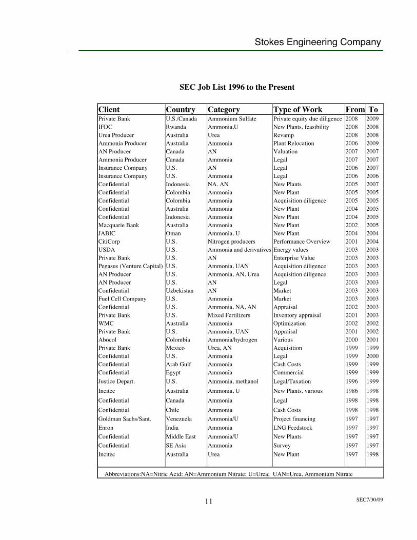
SEC Job List 1996 to the Present
Client Country Category Type of Work From ToPrivate Bank U.S./Canada Ammonium Sulfate Private equity due diligence 2008 2009IFDC Rwanda Ammonia,U New Plants, feasibility 2008 2008Urea Producer Australia Urea Revamp 2008 2008Ammonia Producer Australia Ammonia Plant Relocation 2006 2009AN Producer Canada AN Valuation 2007 2007Ammonia Producer Canada Ammonia Legal 2007 2007Insurance Company U.S. AN Legal 2006 2007Insurance Company U.S. Ammonia Legal 2006 2006Confidential Indonesia NA, AN New Plants 2005 2007Confidential Colombia Ammonia New Plant 2005 2005Confidential Colombia Ammonia Acquisition diligence 2005 2005Confidential Australia Ammonia New Plant 2004 2005Confidential Indonesia Ammonia New Plant 2004 2005Macquarie Bank Australia Ammonia New Plant 2002 2005JABIC Oman Ammonia, U New Plant 2004 2004CitiCorp U.S. Nitrogen producers Performance Overview 2001 2004USDA U.S. Ammonia and derivatives Energy values 2003 2003Private Bank U.S. AN Enterprise Value 2003 2003Pegasus (Venture Capital) U.S. Ammonia, UAN Acquisition diligence 2003 2003AN Producer U.S. Ammonia, AN, Urea Acquisition diligence 2003 2003AN Producer U.S. AN Legal 2003 2003Confidential Uzbekistan AN Market 2003 2003Fuel Cell Company U.S. Ammonia Market 2003 2003Confidential U.S. Ammonia, NA, AN Appraisal 2002 2003Private Bank U.S. Mixed Fertilizers Inventory appraisal 2001 2003WMC Australia Ammonia Optimization 2002 2002Private Bank U.S. Ammonia, UAN Appraisal 2001 2002Abocol Colombia Ammonia/hydrogen Various 2000 2001Private Bank Mexico Urea, AN Acquisition 1999 1999Confidential U.S. Ammonia Legal 1999 2000Confidential Arab Gulf Ammonia Cash Costs 1999 1999Confidential Egypt Ammonia Commercial 1999 1999Justice Depart. U.S. Ammonia, methanol Legal/Taxation 1996 1999Incitec Australia Ammonia, U New Plants, various 1986 1998Confidential Canada Ammonia Legal 1998 1998Confidential Chile Ammonia Cash Costs 1998 1998Goldman Sachs/Sant. Venezuela Ammonia/U Project financing 1997 1997Enron India Ammonia LNG Feedstock 1997 1997Confidential Middle East Ammonia/U New Plants 1997 1997Confidential SE Asia Ammonia Survey 1997 1997Incitec Australia Urea New Plant 1997 1998
Abbreviations:NA=Nitric Acid; AN=Ammonium Nitrate; U=Urea; UAN=Urea, Ammonium Nitrate
Stokes Engineering Company
SEC7/30/0912
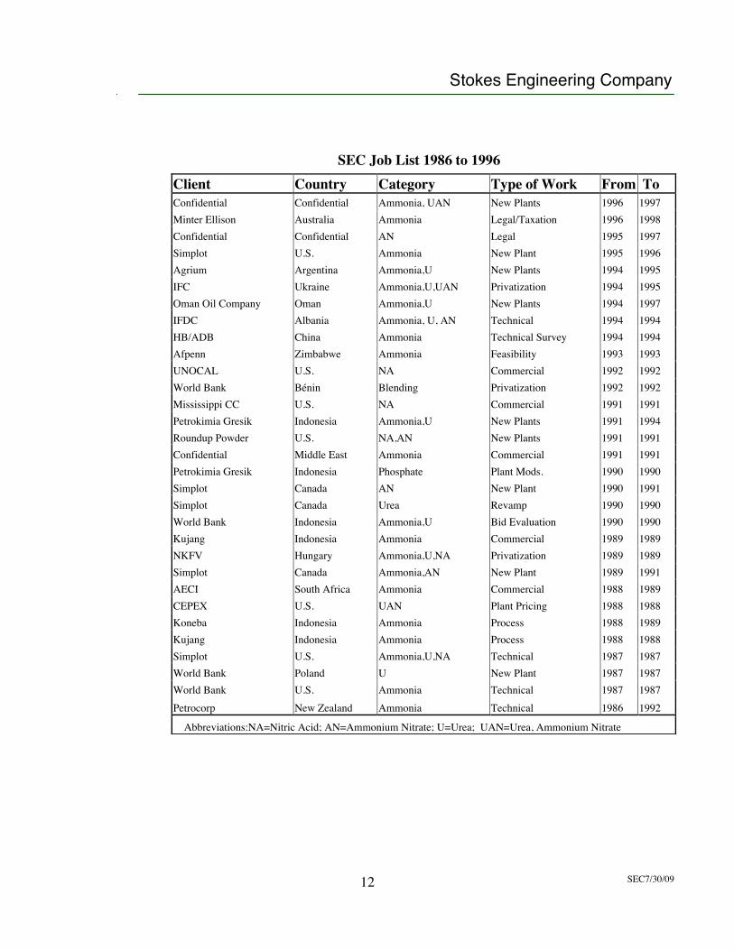
SEC Job List 1986 to 1996Client Country Category Type of Work From ToConfidential Confidential Ammonia, UAN New Plants 1996 1997Minter Ellison Australia Ammonia Legal/Taxation 1996 1998Confidential Confidential AN Legal 1995 1997Simplot U.S. Ammonia New Plant 1995 1996Agrium Argentina Ammonia,U New Plants 1994 1995IFC Ukraine Ammonia,U,UAN Privatization 1994 1995Oman Oil Company Oman Ammonia,U New Plants 1994 1997IFDC Albania Ammonia, U, AN Technical 1994 1994HB/ADB China Ammonia Technical Survey 1994 1994Afpenn Zimbabwe Ammonia Feasibility 1993 1993UNOCAL U.S. NA Commercial 1992 1992World Bank Bénin Blending Privatization 1992 1992Mississippi CC U.S. NA Commercial 1991 1991Petrokimia Gresik Indonesia Ammonia,U New Plants 1991 1994Roundup Powder U.S. NA,AN New Plants 1991 1991Confidential Middle East Ammonia Commercial 1991 1991Petrokimia Gresik Indonesia Phosphate Plant Mods. 1990 1990Simplot Canada AN New Plant 1990 1991Simplot Canada Urea Revamp 1990 1990World Bank Indonesia Ammonia,U Bid Evaluation 1990 1990Kujang Indonesia Ammonia Commercial 1989 1989NKFV Hungary Ammonia,U,NA Privatization 1989 1989Simplot Canada Ammonia,AN New Plant 1989 1991AECI South Africa Ammonia Commercial 1988 1989CEPEX U.S. UAN Plant Pricing 1988 1988Koneba Indonesia Ammonia Process 1988 1989Kujang Indonesia Ammonia Process 1988 1988Simplot U.S. Ammonia,U,NA Technical 1987 1987World Bank Poland U New Plant 1987 1987World Bank U.S. Ammonia Technical 1987 1987Petrocorp New Zealand Ammonia Technical 1986 1992
Abbreviations:NA=Nitric Acid; AN=Ammonium Nitrate; U=Urea; UAN=Urea, Ammonium Nitrate
1/18
Technical Evaluation Reporton
Process Configuration of the Syngas Generation Block (consisting ofthe Shell Coal Gasification technology and Shell ADIP and SRU technology
along with Haldor Topsoe CO Shift and UOP PSA technology)for Collie Coal to Urea Project in Australia
Chiyoda Corporation
July 30 2009
Copy right is vested CHIYODA. May not be reproduced and transmitted without prior written consent of CHIYODA
2/18
Contents :
1. Summary................................................................................................................................ 32. Process Configuration and the Licensed Technologies ......................................................... 33. Comparison of the Licensed Technology of Syngas Generation Block and TechnologySelection ....................................................................................................................................4
3.1 Coal Gasification Technology ....................................................................................... 43.1.1 Comparison of Gasification Technologies and Suppliers.......................................43.1.2 Gasification Technology Selection......................................................................... 4
3.2 CO Shift Technology ....................................................................................................53.2.1 Comparison between Sweet CO Shift and Sour CO Shift .......................................... 53.2.2 Application of Sour CO Shift for this Project ..........................................................63.2.3 CO Shift Technology Selection.............................................................................. 7
3.3 AGR (Acid Gas Removal) Technology ......................................................................... 73.3.1 Comparison of AGR Technologies and Suppliers..................................................73.3.2 AGR Technology Selection ........................................................................................ 7
3.4 SRU (Sulphur Recovery Unit) Technology.................................................................... 83.4.1 Comparison of SRU Technologies and Suppliers ...................................................... 83.4.2 SRU Technology Selection ........................................................................................ 9
3.5 PSA (Pressure Swing Absorption) Technology ..........................................................103.5.1 Comparative Overview of H2 Purification Processes............................................103.5.2 PSA Technology Selection .................................................................................. 10
3.6 Syngas Cleaning Technology ..................................................................................... 114. Safety and Environmental in Shell Coal Gasification Process (SCGP) Technology ............12
4.1 Safety Aspects of Materials Consumed /Produced.....................................................124.2 Safety in Design .........................................................................................................134.3 Environmental............................................................................................................. 14
4.3.1 Gaseous Effluent ................................................................................................. 144.3.2 Liquid Effluent...................................................................................................... 15
5. Attachment........................................................................................................................... 176. Reference ............................................................................................................................ 17
3/18
1. Summary
This report has been prepared by Chiyoda Corporation for Perdaman Chemical and FertilisersPty Ltd to evaluate the package of technologies consisting of Shell Coal Gasification Process(SCGP), Haldor Topsoe CO shift, Shell ADIP for gas cleanup, Shell Paques for SRU and UOPPSA for the H2 purification for Collie Urea Project in Australia. The technology package hasbeen selected with confidence compared with their competitive technologies in theinternational market, in terms of experience, efficiency, economic and environmental.The detailed discussions are made in the relevant paragraph in this report.
2. Process Configuration and the Licensed Technologies
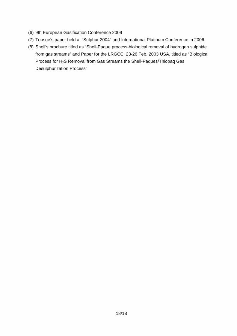
Overall process configuration of this project is composed of two (2) blocks, i.e. the SyngasGeneration Block and the Fertiliser Production Block.The Attachment-1 shows the Block Flow Diagram of Coal Gasification to Fertiliser (Urea)Production with IGCC for the Collie Coal Gasification to Urea Project.The selected licensed process of each block are as follows;
Syngas Generation Block :Composed process of Syngas Generation Block Process LicensorCoal Gasification Shell SCGPCO Shift Topsoe Sour ShiftAGR (Acid Gas Removal) Shell ADIPSRU (Sulphur Recovery Unit) Shell PaquesPSA (Pressure Swing Absorption) UOP
Fertiliser Production Block :Composed process of Fertiliser Production Block Process LicensorAmmonia Process TopsoeUrea Synthesis Process StamicarbonUrea Granulation Process Stamicarbon
4/18
3. Comparison of the Licensed Technology of Syngas Generation Block and TechnologySelection
3.1 Coal Gasification Technology3.1.1 Comparison of Gasification Technologies and Suppliers
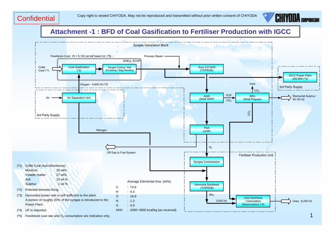
Table-1 provides the comparison of gasification technology data for the Shell SCGPTechnology, Uhde Gasification (Prenflo) Technology, GE (former Texaco)Gasification Technology and COP (former E-Gas) Technology which has alreadybeen proven and commercialized technology and actually in operation.
3.1.2 Gasification Technology SelectionAmong above four (4) proven gasification technologies, it is evaluated that the Shellgasification technology is the best selection for this project with the followingaspects.
SCGP has high cold gas efficiency (ratio of Higher Heating value of Synthesis Gasand Higher Heating value of Coal Feed) because the coal feed is injected into thegasifier dry. In competing technologies the feed is ‘slurry’ of coal in water. As aresult the cold gas efficiency for the Shell dry coal feed process is about 3 percenthigher than the coal water slurry feed gasification process.Due to the dry feeding system, SCGP is able to gasify virtually every coal type: lowquality coals (lignite or brown coal) to anthracite and petcoke. The competitivetechnology of slurry fed system cannot process low rank coals like lignite or browncoal.SCGP has a high carbon conversion of over 99% versus 96-98% for slurry fedcompeting technologies.SCGP uses less oxygen consumption compared to slurry fed competingtechnologies to produce the same amount of syngas, resulting in a smaller AirSeparation Unit capacity.Key component of SCGP – the coal burner has long lifetime. Long-term operationin Nuon’s Buggenum Plant has a proved lifetime of the burners for different coalsof over 20,000 hours. In competing technologies the burners need replacing every1,500 – 4,500 hours.A key technology differentiator is the gasifier membrane wall, which wasdeveloped avoiding a refractory lined vessel not withstanding and slaggingoperating conditions for coal and especially petcoke gasification. The membranewall surrounding the gasification chamber and therefore protecting the gasifiervessel is designed for long operating lifetime exceeding for standard application
5/18
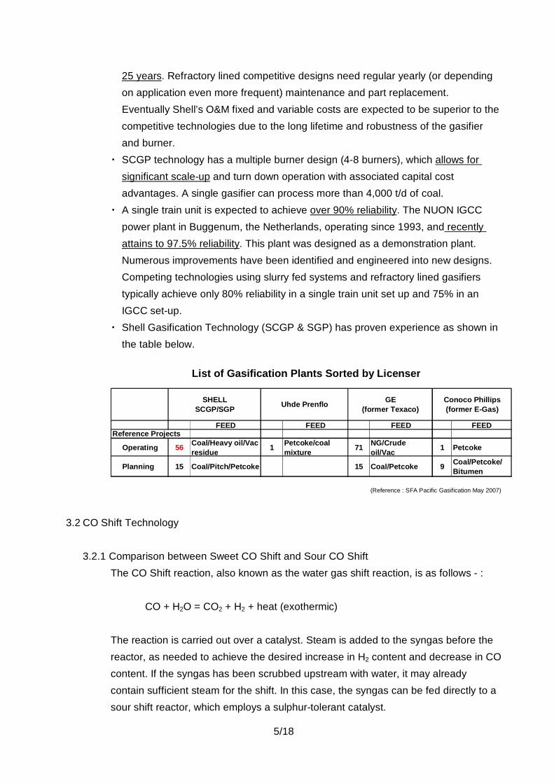
25 years. Refractory lined competitive designs need regular yearly (or dependingon application even more frequent) maintenance and part replacement.Eventually Shell’s O&M fixed and variable costs are expected to be superior to thecompetitive technologies due to the long lifetime and robustness of the gasifierand burner.SCGP technology has a multiple burner design (4-8 burners), which allows forsignificant scale-up and turn down operation with associated capital costadvantages. A single gasifier can process more than 4,000 t/d of coal.A single train unit is expected to achieve over 90% reliability. The NUON IGCCpower plant in Buggenum, the Netherlands, operating since 1993, and recentlyattains to 97.5% reliability. This plant was designed as a demonstration plant.Numerous improvements have been identified and engineered into new designs.Competing technologies using slurry fed systems and refractory lined gasifierstypically achieve only 80% reliability in a single train unit set up and 75% in anIGCC set-up.Shell Gasification Technology (SCGP & SGP) has proven experience as shown inthe table below.
List of Gasification Plants Sorted by Licenser
FEED FEED FEED FEEDReference Projects
Operating 56 Coal/Heavy oil/Vacresidue 1 Petcoke/coal
mixture 71 NG/Crudeoil/Vac 1 Petcoke
Planning 15 Coal/Pitch/Petcoke 15 Coal/Petcoke 9 Coal/Petcoke/Bitumen
(Reference : SFA Pacific Gasification May 2007)
Conoco Phillips(former E-Gas)
GE(former Texaco)
SHELLSCGP/SGP Uhde Prenflo
3.2 CO Shift Technology
3.2.1 Comparison between Sweet CO Shift and Sour CO ShiftThe CO Shift reaction, also known as the water gas shift reaction, is as follows - :
CO + H2O = CO2 + H2 + heat (exothermic)
The reaction is carried out over a catalyst. Steam is added to the syngas before thereactor, as needed to achieve the desired increase in H2 content and decrease in COcontent. If the syngas has been scrubbed upstream with water, it may alreadycontain sufficient steam for the shift. In this case, the syngas can be fed directly to asour shift reactor, which employs a sulphur-tolerant catalyst.
6/18
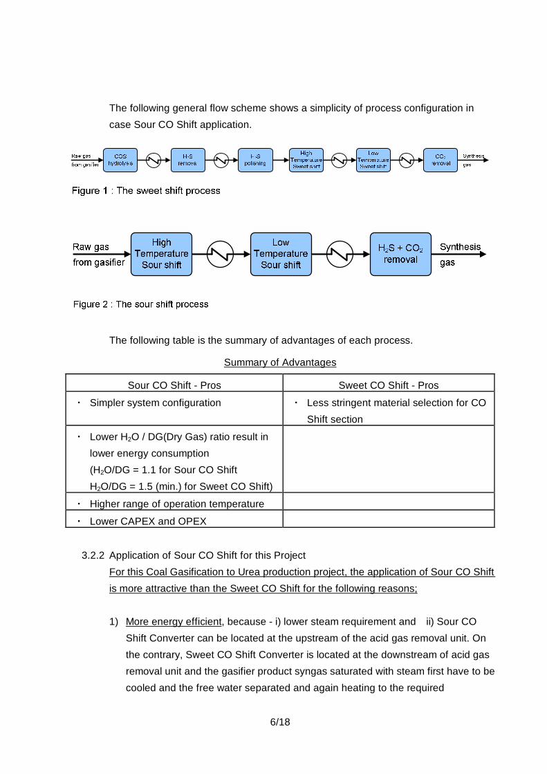
The following general flow scheme shows a simplicity of process configuration incase Sour CO Shift application.
The following table is the summary of advantages of each process.
Summary of Advantages
Sour CO Shift - Pros Sweet CO Shift - Pros
Simpler system configuration Less stringent material selection for COShift section
Lower H2O / DG(Dry Gas) ratio result inlower energy consumption(H2O/DG = 1.1 for Sour CO ShiftH2O/DG = 1.5 (min.) for Sweet CO Shift)
Higher range of operation temperature
Lower CAPEX and OPEX
3.2.2 Application of Sour CO Shift for this ProjectFor this Coal Gasification to Urea production project, the application of Sour CO Shiftis more attractive than the Sweet CO Shift for the following reasons;
1) More energy efficient, because - i) lower steam requirement and ii) Sour COShift Converter can be located at the upstream of the acid gas removal unit. Onthe contrary, Sweet CO Shift Converter is located at the downstream of acid gasremoval unit and the gasifier product syngas saturated with steam first have to becooled and the free water separated and again heating to the required
7/18
temperature for CO Shift is required.
2) Less reactor required, because COS Hydrolysis is done by sour shift catalystthen COS Hydrolysis Reactor with catalyst can be eliminated.
3) Lower investment cost, due to simpler system configuration and lower operatingcost due to higher energy efficiency
3.2.3 CO Shift Technology SelectionApplication of Haldor-Topsoe’s Sour CO Shift technology including proprietarycatalyst to this project is recommendable because it offers a number of the followingclient’s benefits.
1) superior shift activity in a sulphur-containing syngas, resulting in significantprocess simplification and reduced energy consumption compared to thetraditional sweet shift catalyst
2) the catalyst can operate in a broad temperature range and a wide range of steamto carbon monoxide ratios, resulting in increased flexibility in the operation of thewater-gas shift section
3) flexible shift trains consisting of one or multiple reactors with inter-cooling eitherfor maximum carbon monoxide (CO) conversion or for production of syngas witha wide range of hydrogen to CO ratios
4) conversion of carbonyl sulphide to hydrogen sulphide by hydrolysis5) conversion of hydrogen cyanide to carbon monoxide and ammonia by hydrolysis6) the use of simple adiabatic shift reactors reduces capital cost and ensures simple
operation7) Haldor-Topsoe can guarantee the process performance as CO Shift whole
system including the performance of Topsoe’s proprietary catalyst.
3.3 AGR (Acid Gas Removal) Technology3.3.1 Comparison of AGR Technologies and Suppliers
There are four (4) of the most widely used AGR technologies for coal-derived syngasAGR,i) ADIP ii) MDEA iii) Selexol iv) Rectisol.Table-2 provides the comparison of characteristics of each licensed technology.
3.3.2 AGR Technology SelectionAmong above four (4) proven AGR technologies, it is evaluated that the MDEAbased AGR (Shell ADIP or Sulfinol) technology is the proper selection for this project
8/18
in the following aspects.
1) Acid gas treatment process selection begins the acid gas reduction required tomeet downstream process. And the deep removal of H2S and CO2 by means ofphysical absorption such as Selexol and Rectisol are not necessary for thisproject. And the H2S and CO2 removal by amine solution base is adequate,because the PSA unit is provided at the downstream for H2 purification.
2) Lower energy consumption because of absorption at ambient temperature level(while refrigeration is required in the Selexol and Rectisol processes)
3) The next step is to determine which AGR technology is the most economicallyattractive. As can be shown in the Table-2, MDEA based AGR technology ofShell ADIP or Sulfinol is the least investment cost rather than those of Selexoland Rectisol.
4) CO2 capture can be realized with the integration of SRU (Sulphur Recovery Unit)technology of Shell Paques process.
5) As shown in the Table-2, proven technology which has many experiencedprojects in the world. A comparable scale AGR has been delivered for theWoodside Pluto LNG project in Western Australia.
3.4 SRU (Sulphur Recovery Unit) Technology3.4.1 Comparison of SRU Technologies and Suppliers
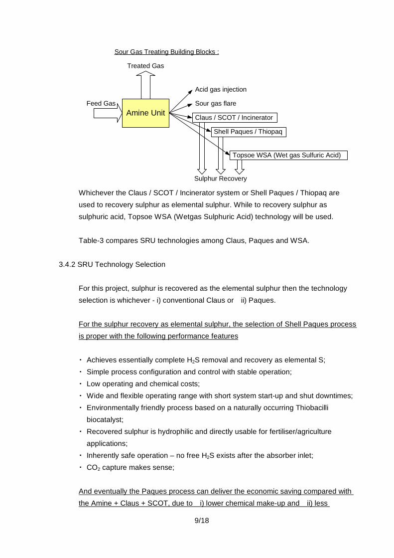
The following sketch shows the Sour Gas Treating Building Blocks.
9/18
Amine UnitFeed Gas
Treated Gas
Sour Gas Treating Building Blocks :
Acid gas injection
Sour gas flare
Claus / SCOT / Incinerator
Shell Paques / Thiopaq
Topsoe WSA (Wet gas Sulfuric Acid)
Sulphur Recovery
Whichever the Claus / SCOT / Incinerator system or Shell Paques / Thiopaq areused to recovery sulphur as elemental sulphur. While to recovery sulphur assulphuric acid, Topsoe WSA (Wetgas Sulphuric Acid) technology will be used.
Table-3 compares SRU technologies among Claus, Paques and WSA.
3.4.2 SRU Technology Selection
For this project, sulphur is recovered as the elemental sulphur then the technologyselection is whichever - i) conventional Claus or ii) Paques.
For the sulphur recovery as elemental sulphur, the selection of Shell Paques processis proper with the following performance features
Achieves essentially complete H2S removal and recovery as elemental S;Simple process configuration and control with stable operation;Low operating and chemical costs;Wide and flexible operating range with short system start-up and shut downtimes;Environmentally friendly process based on a naturally occurring Thiobacillibiocatalyst;Recovered sulphur is hydrophilic and directly usable for fertiliser/agricultureapplications;Inherently safe operation – no free H2S exists after the absorber inlet;CO2 capture makes sense;
And eventually the Paques process can deliver the economic saving compared withthe Amine + Claus + SCOT, due to i) lower chemical make-up and ii) less
10/18
equipment to operate and maintain.
3.5 PSA (Pressure Swing Absorption) Technology
3.5.1 Comparative Overview of H2 Purification ProcessesPSA, Membrane separation and Cryogenic separation are the three (3) principleoptions for purification of hydrogen.Table-4 “Hydrogen Purification Technology Selection Criteria” provides thecomparison among three technologies and major considerations in the selection oftechnologies.
3.5.2 PSA Technology Selection
The selection of PSA for H2 purification is the best with the following aspects.
1) PSA is the dominant recovery technology used in new hydrogen plants. Forexample, PSA is the recovery technology of choice in North America, whereabout 40% of the world refinery hydrogen capacity is located.
2) An older but less effective purification technology, which has been largelysupplanted by PSA, but is still in limited use, employs amine scrubbing to removemost of the CO2 – followed by reacting the CO and residual CO2 with H2 over acatalyst to form methane. This type of methanation process is also the basis forH2 purification. The purity after methanation is 97-98 mol% H2, the remainderbeing methane and nitrogen introduced with the feed coal or the oxygen.And these impurities in the H2 product result in higher energy consumption in theammonia synthesis due to higher ammonia synthesis pressure requirement dueto compensate the partial pressure of the inert components (CH4, N2, Ar) and inhigher investment cost due to provision of PGRU (Purge Gas Recovery Unit)where the purge gas continuously is purged from the ammonia synthesis loop toavoid the accumulation of inert component.
3) Among three (3) principle H2 purification process (PSA, Membrane, Cryogenic),PSA is the best choice with the following reasons, a) highest H2 Purity b) CO +CO2 (which are poisonous to ammonia synthesis catalyst) removal c) higher H2
11/18
Production pressure d) higher reliability e) no major utility requirements at allf) capital cost advantageous considering not only PSA cost but also cost causedby higher energy consumption and other additional equipment requirement inother Membrane and Cryogenic cases. (Details are referred to the Table-4Hydrogen Purification Technology Selection Criteria)
4) Proven technology which has many experienced projects in the world.
3.6 Syngas Cleaning Technology
The syngas produced from the coal gasification is treated via the each cleaning technologyas follows;
(1) Particle RemovalDry solids removal systems use ceramic filters that can remove all solids from thegas at temperatures between 300 and 500 °C. Above 500 °C, alkali compounds maypass the filters. Below 300 °C, the filters may be blinded of deposits of ammoniumchloride (NH4Cl). Including cyclones upstream will reduce the loading on the filtersand therefore also the risk of breakage.
(2) Chloride (HCl) and Ammonia (NH3) RemovalEven if an IGCC plant has ceramic filter it usually also adds a water scrubbingsystem for removal of remaining impurities such as chloride (HCl) and ammonia(NH3). It is noted that the coal has a modest chloride content, well within the standarddesign.
(3) Metal Carbonyls RemovalIron and nickel carbonyls (Fe(CO)5 , Ni(CO)4) are both undesirable tracecomponents in synthesis gases.Metal Carbonyls are existed as vapor phase in the syngas from the Syngas coolerand can be absorbed in the organic solution of the downstream AGR.Also in the IGCC case, nickel carbonyls are damaging to combustion turbines butcan be removed from syngas by activated carbon.
(4) Mercury RemovalMercury content in the syngas is depend upon the quality of coal feedstock.In case the content of mercury in the syngas is higher than the environmental
12/18
specification, activated carbon will be provided so that it removes 90-95% of themercury from coal derived synthesis gas. Mercury sulfide on the spent carbon isstable and currently the best option is to dispose of it at certified storage sites.Regeneration with mercury recovery is complex and expensive.
4. Safety and Environmental in Shell Coal Gasification Process (SCGP) Technology
4.1 Safety Aspects of Materials Consumed /Produced
The SCGP design information is prepared according to oil and petrochemical design,construction and operating regulations, guidelines, procedures and practices.
The following materials are consumed/produced and will be briefly discussed:
CoalIn general non-toxic, but repeated inhalation of high concentrations of coal dust particlescould result in pneumoconiosis. Equipment design will prevent such concentrations duringnormal operation. In case of leakages, appropriate equipment and work practices willprevent inhalation. Two other properties of pulverized coal which affect storage andhandling are its tendency to undergo spontaneous combustion in air and the possibility offorming explosive mixtures of coal dust and air. The SGCP process uses nitrogen toinertize all the equipment in which pulverized coal is handled.
OxygenOxygen is a strong oxidizing agent and greatly accelerates normally non-hazardousconditions. Selection of proper materials and proper installation, cleaning and operatingtechniques will prevent this.
NitrogenNitrogen being physiologically virtually inert can cause asphyxiation. Entry into confinedspaces should therefore always be proceeded by proper procedures (e.g. oxygenconcentration measurements).
Carbon MonoxideCarbon Monoxide is a toxic gas. Long-term exposures should not exceed the T(hreshold)L(imit) V(alue) of 50 ppm. Vent gases potentially containing CO are flared, therefore. Gas
13/18
detectors in strategic locations will give an early warning of leakages and the use of properprocedures and safety equipment during maintenance will prevent inhalation.
HydrogenHydrogen is not toxic gas, but is highly flammable.
Hydrogen SulfideHydrogen Sulfide is a toxic gas. Although it has a strong unpleasant odor initially, itanesthesizes the senses quickly so smell is not a reliable indicator. Exposure should notexceed the current TLV of 10 ppm. Gas detectors in strategic locations will give an earlywarning.
Sulphur DioxideSulphur Dioxide is a toxic gas. Traces of sulphur dioxide is produced only in the gas turbine,the flare and incinerator and can be produced by burning sulphur. Exposure should notexceed the current TLV of 2 ppm.
SulphurSulphur is an inert material present in liquid form within the plant. Three properties arerelevant here:
1) Its melting point of 113 °C, which can potentially cause plugging in lines, etc. (to beresolved by “steaming”) and,
2) Its (low) “inflammability”, producing sulphur dioxide.3) Sulphur can contain traces of H2S. A toxic vapour can therefore be formed above
non-stripped liquid sulphur.
Inflammable MaterialsThe SCGP does not use any highly inflammable materials which require more thancommon sense in storage, use, etc.
Corrosive ReagentsA number of corrosive reagents are used in the process, e.g. caustic, acid, solvents, etc.These materials create no hazards if used as prescribed/designed and if protective clothingis used if they are handled.
4.2 Safety in Design
14/18
During the design phase, the Process Safety Flow Schemes (PSFS) and the safetymemorandum have to be developed. The PSFS’s and safety memorandum give acomprehensive overview and description of all the safety requirements. During thedevelopment of the P(process) F(flow) S(Schemes) the following philosophy, besidesstandard equipment design/material selection requirements, is used:
Instrumentation used for control should not be used for safeguarding. Separateinstruments are thus required for the safeguarding.Incompatible gaseous environments should be separated by double block and bleedersystems.Different pressure levels of similar environments are separated by double block valves(batchwise discharge after pressure equalization) or control valve plus automatedemergency shut-off valve (continuous discharge). Moreover, a pressure relief valve isinstalled on the lower pressure equipment for ultimate protection in case of“breakthrough”.Pressure relief valves or rupture discs with relief to a safe location are installed on allequipment which can be isolated and can build up pressure internally (e.g. heat ofreaction).Where more appropriate, pressure reliefs are installed on the supply/discharge linesto/from equipment.Standard safety procedures (purging, flame eyes, etc.) for fired equipment.Minimum operating pressures for nitrogen/steam/hot water systems used for purgingand/or heat transfer are higher than the maximum reachable pressure (relief valvepressure setting) of the oxygen and/or syngas systems being purged/heated.Relief systems/vents (potentially) containing highly flammable and/or toxic gases will beconnected to the flare system (others will be atmospheric vents, where required, e.g. HPsteam - with silencers).Adequate depressurising valves are installed for depressuring in case of fire.
Coolers with high-pressure syngas on the process side require special attention if they areconnected to a cooling water system at a lower pressure. Also coolers of HP water, incontact with an HP syngas environment, require special attention if they are connected to acooling water system at a lower pressure (e.g. scrubber water cooler).
4.3 Environmental
4.3.1 Gaseous Effluent
15/18
The gas products from the Shell Coal Gasification Process Demonstration Plant inDeer park, Texas, are environmentally clean. A series of scrubbing steps removesdust, sulphur compounds, and other impurities from the syngas, producing amedium-Btu fuel gas product that contains only 10 to 20 ppmw sulphur compound,essentially all as carbonyl sulfide (Perdaman specification max. 50 ppmw). Acid gasfrom the Sulfinol® stripper and the sour slurry stripper contains hydrogen sulfide andcarbon dioxide, together with minor traces of a few volatile organic compounds; theinorganic impurities in the acid gas are not expected to affect the marketability of thesulphur product from the Paques sulphur recovery process. As part of an overallresearch and development effort to improve the gas cleanup process still further, theperformance of two selective amine solvents in treating syngas has beendemonstrated in a slip-stream gas treating process development unit.
For this Collie Coal to Urea project, Shell ADIP as AGR and UOP PSA for H2
purification system have been selected. Shell ADIP absorbs the CO2 and H2Sgenerated in the Sour Shift Unit. Acid gas (CO2 + H2S) is sent to the Shell –Paques unit.Shell-Paques unit, which converts the H2S in both the CO2 stream to Urea Plant andthe AGR Acid Gas stream into biosulphur. The CO2 rich gases contain less than 4ppmv of H2S. Excess CO2 is vented with the remainder sent to the Ureamanufacturing plant through an H2S guard bed to ensure an H2S content meeting therequired specifications.The treated syngas via AGR contains H2S (< 10 ppmv) and PSA (at downstream ofAGR) has capability to remove H2S which is poisonous to the catalyst atdownstream.
Environmental information obtained during a 1,528-hour demonstration run in whichIllinois No. 5 coal was gasified, together with results from continuing studies on othercoals and from gas treating studies in slip-stream process development unit, indicatethat the Shell Coal Gasification Process will meet all current and foreseeable futureenvironmental regulations on gaseous effluent streams. Shell has in hand designoptions to provide full-scale plants with the capability to gasify economically a widevariety of coals, even lignites and sub-bituminous coals, while meeting applicableenvironmental regulations at any site.
4.3.2 Liquid Effluent
This paragraph, contains the results of chemical and toxicological characterizations
16/18
of the complete aqueous effluent from the SCGP demonstration plant duringgasification of high-sulphur, bituminous coals. Results from the demonstration plant,along with studies from a slipstream process development unit, confirm that thetreated aqueous effluent from the Shell Coal Gasification Process (SCGP) isenvironmentally clean.
The untreated aqueous bleed stream consists of water condensed from the rawproduct gas, water from raw gas cleaning and slurry pumping of wet scrubbed solids,condensate from sour slurry stripping, bleed water from slag cooling, and bleedwater from acid gas solvent stripping.
Steps in the treatment of the process blowdown water to produce clean effluentinclude: collection and stabilization of wash water from gas scrubbing; pressurelet-down; steam stripping for removal of dissolved gases; flocculation, clarificationand thickening of suspended, fine particulates; and biological oxidation of inorganicsalts of nitrogen and sulphur. Wash water containing suspended particulate matterfrom process cleaning operations is also combined with the process blowdownduring clarification.
Gasification at very high temperature (over 1500 °C) ensures the destruction of tars,phenols, and other hydrocarbons heavier than methane. This feature provides asignificant environmental advantage for SCGP. Results of extensive analyses verifythat no hydrocarbon heavier than methane, nor any other volatile or semi-volatileorganic compound is detectable in the process gas or aqueous blowdown.
Biological treatment provides oxidization for the small amounts of inorganic nitrogenand sulphur species that remain in the water, and produces an effluent suitable fordischarge. Complete chemical characterization of the biologically treated effluent isprovided. The biological oxidation of nitrogen and sulphur species results in a verylow biomass yield. Several types of biological treatment reactors, suitable foroperation at low-yield conditions, have been demonstrated. These biologicaltreatment reactors have provided ample design data for a commercial facility.
The treated effluent contains fully oxidized products from biological treatment andvery low concentrations of trace metals. Both acute and chronic toxicity testing of thetreated effluent indicate that no adverse impact on receiving waters would result froma commercial facility that discharges biologically treated effluent. For example, noacute toxicity was detectable, and any detectable chronic toxicity could be eliminated

17/18
by installation of a discharge diffuser providing only a minor amount of dilution.
The ability to remove the trace amounts of non-toxic, total cyanide that remains afterconventional biological treatment has been demonstrated by means of enhancedbiological treatment and by means of physical and chemical treatment. Also theability to remove non-toxic, nitrate salt has been demonstrated by means ofbiological denitrification.
The slipstream process development unit provides a flexible and efficient means ofdata collection, applicable to commercial scale design, over a wide range ofoperating conditions. The slipstream process development unit continues to operateduring gasification of other coals, including sub-bituminous coal and lignite. Datafrom this operation supports the claim that SCGP can be designed to gasify a widerange of feedstocks in an environmentally acceptable manner.
5. Attachment
Attachment-1 : Block Flow Diagram of Coal Gasification to Fertiliser Production with IGCCTable-1 : Comparison of Gasification Technologies among Shell, Uhde, GE and COPTable-2 : Comparison of AGR Technologies among ADIP, MDEA, Selexol and Rectisol.Table-3 : Comparison of SRU Technologies among Claus, Paques and WSATable-4 : Hydrogen Purification Technology Selection Criteria
6. Reference
(1) SFA Pacific, Inc, GASIFICATION Critical Analysis of Technology, Economics, Markets, May2007
(2) SRI PEP Report No. 154/154A/154B/216(3) Chemsystems PERP Coal Gasification Technologies 03/04S11(4) DOE/NETL-2007/1281 Cost and Performance Baseline for Fossil Energy Plants
(Aug-2007)(5) 8th European Gasification Conference 2007
18/18
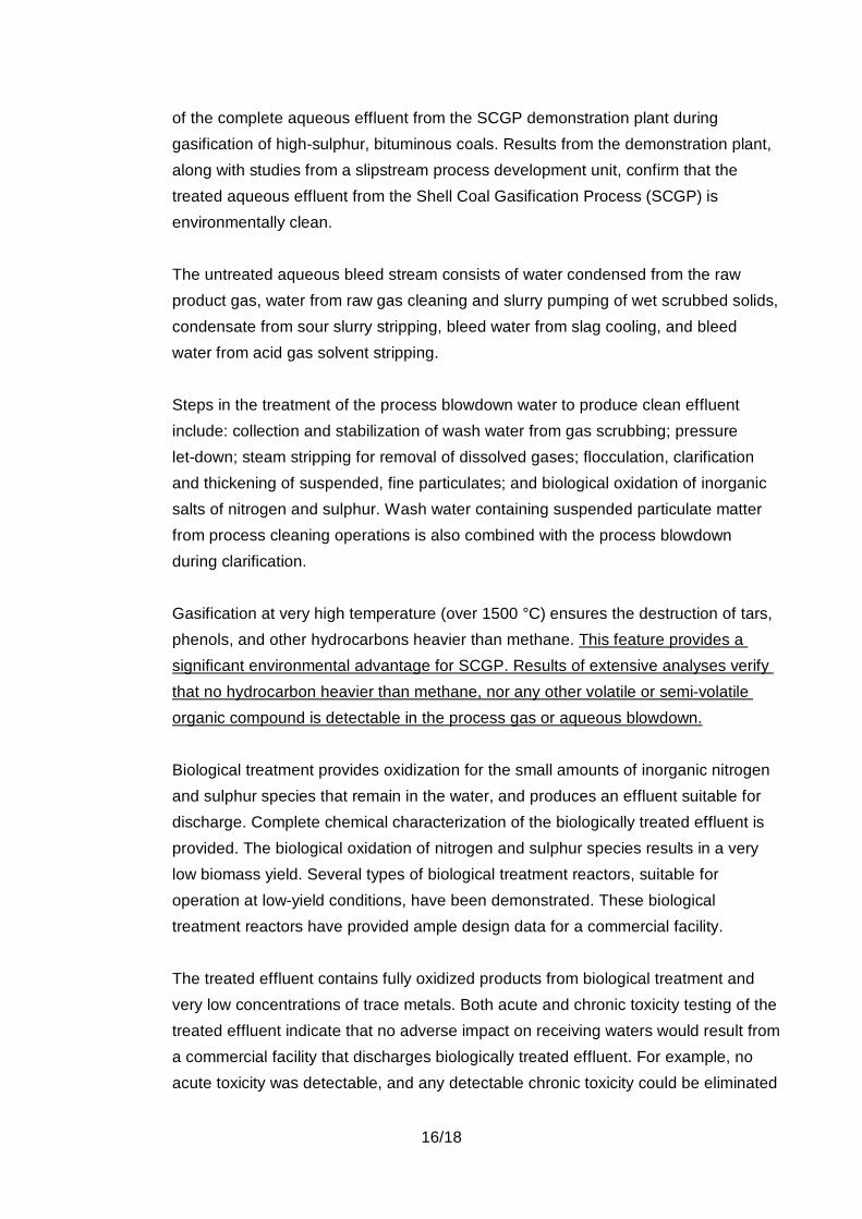
(6) 9th European Gasification Conference 2009(7) Topsoe’s paper held at “Sulphur 2004” and International Platinum Conference in 2006.(8) Shell’s brochure titled as “Shell-Paque process-biological removal of hydrogen sulphide
from gas streams” and Paper for the LRGCC, 23-26 Feb. 2003 USA, titled as “BiologicalProcess for H2S Removal from Gas Streams the Shell-Paques/Thiopaq GasDesulphurization Process”
1
Confidential Copy right is vested CHIYODA. May not be reproduced and transmitted without prior written consent of CHIYODA
SHELL SCGP
Oxygen : 4,600 t/d (*5)
Feedstock Coal : W = 5,100 (at daf base) t/d (*5)
Nitrogen
Elemental Sulphur : 40~50 t/d
Urea : 6,200 t/d
Off Gas to Fuel System
Air
H2
CO
2
NH3
CollieCoal (*1)
3rd Party Supply
3rd Party Supply
3,500 t/d
Syngas Generation Block
Fertiliser Production Unit
Process Steam
H2S/
CO2
CO2
Vent
Syngas Cooling / Wet Scrubbing / Slag Handling
AGR(Shell ADIP)
IGCC Power Plant205 MW (*3)
Syngas Compression
Ammonia Synthesis (TOPSOE)
Sour CO Shift(TOPSOE)
SRU(Shell Paques)
Urea Synthesis/ Granulation
(Stamicarbon) (*4)
Coal Gasification(*2)
Air Separation Unit
PSA(UOP)
Attachment -1 : BFD of Coal Gasification to Fertiliser Production with IGCC
(*1) Collie Coal (sub-bituminous) :Moisture : 25 wt%Volatile matter : 27 wt%Ash : 10 wt %Sulphur : 1 wt %
(*2) Potential biomass firing.
(*3) Generated power rate is self sufficient to the plant.A portion of roughly 20% of the syngas is introduced to the Power Plant.
(*4) UF is imported.
(*5) Feedstock coal rate and O2 consumption are indicative only.
Average Elemental Ana. (wt%)
C : 74.6H : 4.4O : 18.8N : 1.3S : 0.9HHV : 4300~4900 kcal/kg (as received)
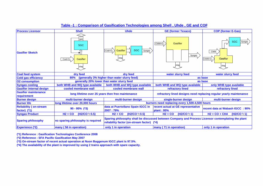
Table -1 : Comparison of Gasification Technologies among Shell , Uhde , GE and COPProcess Licensor Shell Uhde GE (former Texaco) COP (former E-Gas)
Gasifier Sketch
Coal feed system dry feed dry feed water slurry feed water slurry feedCold gas efficiencyO2 consumptionSyngas cooling both WHB and WQ type available both WHB and WQ type available both WHB and WQ type available only WHB type availableGasifier internal design cooled membrane wall cooled membrane wall refractory lined refractory linedGasifier maintenancerequirementBurner design multi-burner design multi-burner design single-burner design multi-burner designBurner life long lifetime over 20,000 hoursReliability ( on-streamfactor) (*1) 90 - 95% (*3) data at Puertollano Spain IGCC in
2007 : 79%recent actual at GE representativeplant : 95% recent data at Wabash IGCC : 90%
Syngas Product H2 + CO (H2/CO≒0.5) H2 + CO (H2/CO≒0.5) H2 + CO (H2/CO≒1) H2 + CO + CH4 (H2/CO≒1)
Sparing philosophy no sparing philosophy is required
Experience (*2) many ( 56 in operation) only 1 in operation many ( 71 in operation) only 1 in operation
(*1) Reference : Gasification Technologies Conference 2008(*2) Reference : SFA Pacific Gasification May 2007(*3) On-stream factor of recent actual operation at Nuon Buggenum IGCC plant is 97.5%.(*4) The availability of the plant is improved by using 2 trains approach with spare capacity.
80% (generally 3% higher than water slurry feed)generally 20% lower than water slurry feed
Sparing philosophy shall be discussed between Company and Process Licensor contemplating the plantreliability factor (on-stream factor) (*4)
burners need replacing every 1,500-4,500 hours
long lifetime over 25 years then free maintenance refractory lined designs need replacing regular yearly maintenance
as baseas base
Gasifier
SGC
slag
Coal+O2
Syngas
Gasifier
Syngas
CWM+O 2
slag
Coal+O2 Gasifier SGC Syngas
CWM+O 2
CWM
slag
SGC Syngas
slag
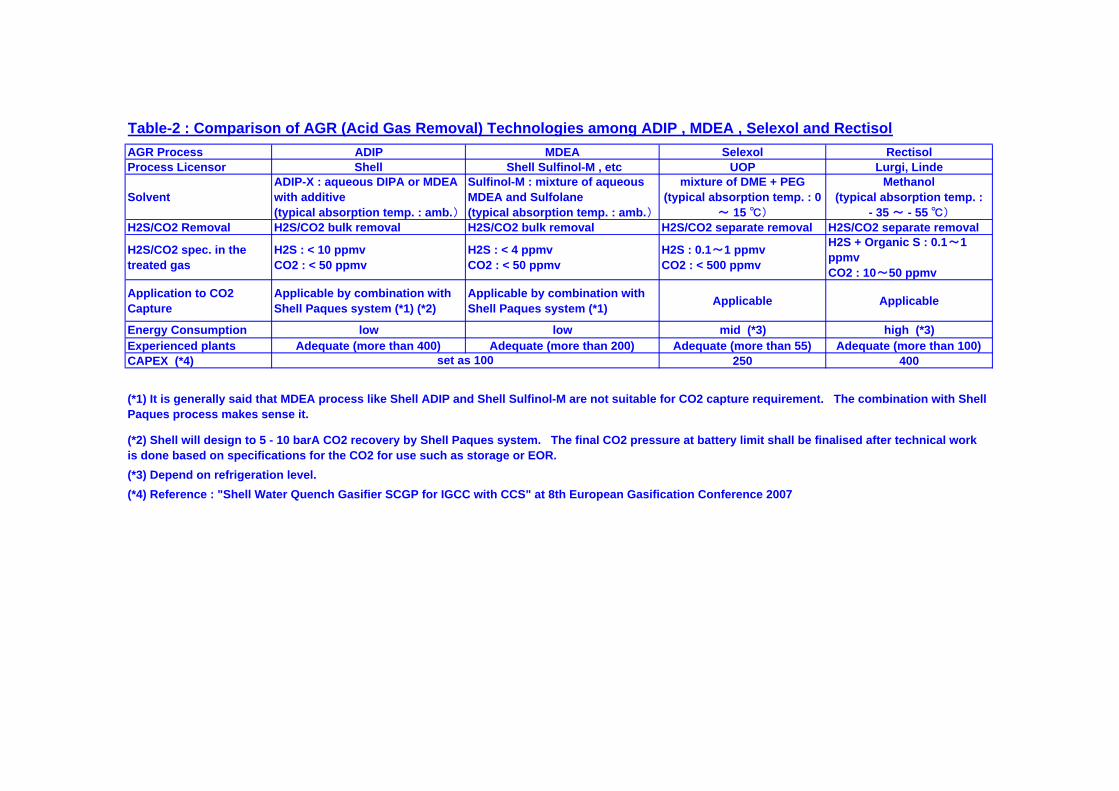
Table-2 : Comparison of AGR (Acid Gas Removal) Technologies among ADIP , MDEA , Selexol and RectisolAGR Process ADIP MDEA Selexol RectisolProcess Licensor Shell Shell Sulfinol-M , etc UOP Lurgi, Linde
SolventADIP-X : aqueous DIPA or MDEAwith additive(typical absorption temp. : amb.)
Sulfinol-M : mixture of aqueousMDEA and Sulfolane(typical absorption temp. : amb.)
mixture of DME + PEG(typical absorption temp. : 0
~ 15 ℃)
Methanol(typical absorption temp. :
- 35 ~ - 55 ℃)
H2S/CO2 Removal H2S/CO2 bulk removal H2S/CO2 bulk removal H2S/CO2 separate removal H2S/CO2 separate removal
H2S/CO2 spec. in thetreated gas
H2S : < 10 ppmvCO2 : < 50 ppmv
H2S : < 4 ppmvCO2 : < 50 ppmv
H2S : 0.1~1 ppmvCO2 : < 500 ppmv
H2S + Organic S : 0.1~1ppmvCO2 : 10~50 ppmv
Application to CO2Capture
Applicable by combination withShell Paques system (*1) (*2)
Applicable by combination withShell Paques system (*1) Applicable Applicable
Energy Consumption low low mid (*3) high (*3)Experienced plants Adequate (more than 400) Adequate (more than 200) Adequate (more than 55) Adequate (more than 100)CAPEX (*4) 250 400
(*4) Reference : "Shell Water Quench Gasifier SCGP for IGCC with CCS" at 8th European Gasification Conference 2007
(*1) It is generally said that MDEA process like Shell ADIP and Shell Sulfinol-M are not suitable for CO2 capture requirement. The combination with ShellPaques process makes sense it.
(*2) Shell will design to 5 - 10 barA CO2 recovery by Shell Paques system. The final CO2 pressure at battery limit shall be finalised after technical workis done based on specifications for the CO2 for use such as storage or EOR.
set as 100
(*3) Depend on refrigeration level.
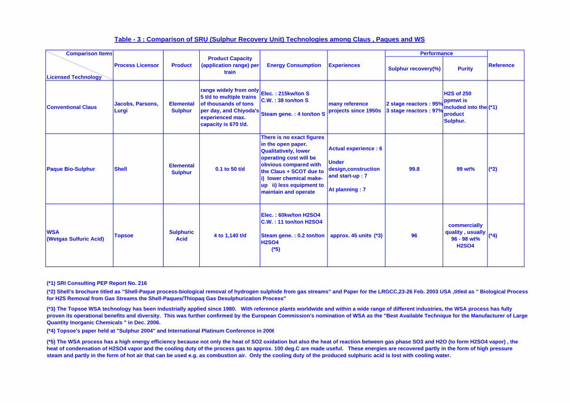
Table - 3 : Comparison of SRU (Sulphur Recovery Unit) Technologies among Claus , Paques and WS
Comparison Items
Licensed TechnologySulphur recovery(%) Purity
Conventional Claus Jacobs, Parsons,Lurgi
ElementalSulphur
range widely from only5 t/d to multiple trainsof thousands of tonsper day, and Chiyoda'sexperienced max.capacity is 670 t/d.
Elec. : 215kw/ton SC.W. : 38 ton/ton S
Steam gene. : 4 ton/ton S
many referenceprojects since 1950s
2 stage reactors : 95%3 stage reactors : 97%
H2S of 250ppmwt isincluded into theproductSulphur.
(*1)
Paque Bio-Sulphur Shell ElementalSulphur 0.1 to 50 t/d
There is no exact figuresin the open paper.Qualitatively, loweroperating cost will beobvious compared withthe Claus + SCOT due toi) lower chemical make-up ii) less equipment tomaintain and operate
Actual experience : 6
Underdesign,constructionand start-up : 7
At planning : 7
99.8 99 wt% (*2)
WSA(Wetgas Sulfuric Acid) Topsoe Sulphuric
Acid 4 to 1,140 t/d
Elec. : 60kw/ton H2SO4C.W. : 11 ton/ton H2SO4
Steam gene. : 0.2 ton/tonH2SO4 (*5)
approx. 45 units (*3) 96
commerciallyquality , usually
96 - 98 wt%H2SO4
(*4)
(*4) Topsoe's paper held at "Sulphur 2004" and International Platinum Conference in 2006
Experiences
(*2) Shell's brochure titled as "Shell-Paque process-biological removal of hydrogen sulphide from gas streams" and Paper for the LRGCC,23-26 Feb. 2003 USA ,titled as " Biological Processfor H2S Removal from Gas Streams the Shell-Paques/Thiopaq Gas Desulphurization Process"
(*5) The WSA process has a high energy efficiency because not only the heat of SO2 oxidation but also the heat of reaction between gas phase SO3 and H2O (to form H2SO4 vapor) , theheat of condensation of H2SO4 vapor and the cooling duty of the process gas to approx. 100 deg.C are made useful. These energies are recovered partly in the form of high pressuresteam and partly in the form of hot air that can be used e.g. as combustion air. Only the cooling duty of the produced sulphuric acid is lost with cooling water.
(*3) The Topsoe WSA technology has been industrially applied since 1980. With reference plants worldwide and within a wide range of different industries, the WSA process has fullyproven its operational benefits and diversity. This was further confirmed by the European Commission's nomination of WSA as the "Best Available Technique for the Manufacturer of LargeQuantity Inorganic Chemicals " in Dec. 2006.
Reference
Performance
Process Licensor ProductProduct Capacity
(application range) pertrain
Energy Consumption
(*1) SRI Consulting PEP Report No. 216
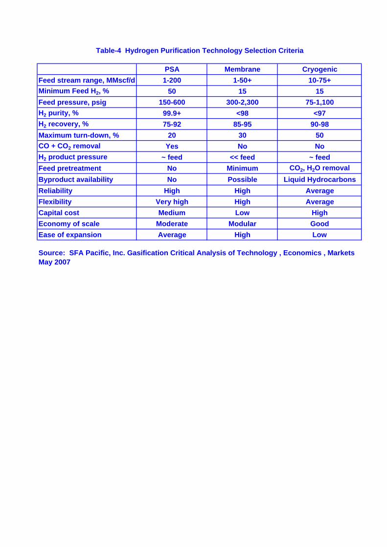
Table-4 Hydrogen Purification Technology Selection Criteria
PSA Membrane CryogenicFeed stream range, MMscf/d 1-200 1-50+ 10-75+Minimum Feed H2, % 50 15 15Feed pressure, psig 150-600 300-2,300 75-1,100H2 purity, % 99.9+ <98 <97H2 recovery, % 75-92 85-95 90-98Maximum turn-down, % 20 30 50CO + CO2 removal Yes No NoH2 product pressure ~ feed << feed ~ feedFeed pretreatment No Minimum CO2, H2O removalByproduct availability No Possible Liquid HydrocarbonsReliability High High AverageFlexibility Very high High AverageCapital cost Medium Low HighEconomy of scale Moderate Modular GoodEase of expansion Average High Low
Source: SFA Pacific, Inc. Gasification Critical Analysis of Technology , Economics , MarketsMay 2007