Embed Size (px)
Citation preview
Joint Standard Document between Energex and Ergon Energy
Energex Limited ABN 40 078 849 055 Ergon Energy Corporation Limited ABN 50 087 646 062
Asset Standard
Standard for Electric and Magnetic
Field Design
These standards created and made available are for the construction of Energy Queensland
infrastructure. These standards ensure meeting of Energy Queensland's requirements. External
companies should not use these standards to construct non-Energy Queensland assets.
If this standard is a printed version, to ensure compliance, reference must be made to the Energy
Queensland internet site to obtain the latest version.
Approver Carmelo Noel – GM Asset Standards
If RPEQ sign off required insert details below.
Energy Queensland
Certified Person name and Position Registration Number
John Lansley
Manager Substation Standards
RPEQ 6371
Abstract: The aim of this document is to establish guidelines for electric and magnetic fields (EMF),
calculation and measurement of these fields and design guidelines for new infrastructure to
minimise impact.
Keywords: Electric Field, Magnetic Field, EMF, transmission line, substation
Standard for Electric and Magnetic
Field Design
Check this is the latest version before use ii EX 02320 Ver 1
EE STNW3042 Ver 1
Joint Standard Document between Energex and Ergon Energy
Energex Limited ABN 40 078 849 055 Ergon Energy Corporation Limited ABN 50 087 646 062
For definitive document version and control detail, please refer to the information stored on the
Process Zone and RED.
Revision history
Revision date Version
number
Author Description of change/revision
14/09/2021 1.0 J.Lansley Combined requirements from RED 365
and Ergon ES000904R104
Revised to new template

Standard for Electric and Magnetic
Field Design
Check this is the latest version before use iii EX 02320 Ver 1
EE STNW3042 Ver 1
Joint Standard Document between Energex and Ergon Energy
Energex Limited ABN 40 078 849 055 Ergon Energy Corporation Limited ABN 50 087 646 062
Table of Contents
1 Overview .............................................................................................................................. 1
1.1 Purpose ......................................................................................................................... 1
1.2 Application .................................................................................................................... 1
2 References ........................................................................................................................... 1
2.1 EQL controlled documents ............................................................................................ 1
2.2 Other documents ........................................................................................................... 2
3 Legislation, regulations, rules, and codes ............................................................................. 2
4 Definitions and abbreviations ................................................................................................ 3
4.1 Definitions ..................................................................................................................... 3
4.2 Abbreviations ................................................................................................................ 4
5 EMF Definitions and Basic s ................................................................................................. 4
5.1 General ......................................................................................................................... 4
5.2 Electric Fields ................................................................................................................ 5
5.3 Magnetic Fields ............................................................................................................. 5
5.4 How does EMF decrease with distance? ....................................................................... 6
5.5 High fields around electricity distribution and transmission utility environments. ............ 6
6 ARPANSA Guidelines and Recommended Exposure Limits ................................................. 7
6.1 General ......................................................................................................................... 7
6.2 Reference Levels .......................................................................................................... 7
6.3 Assessing compliance with exposure limits for occupational hazards ............................ 8
6.4 Other lawful directions ................................................................................................... 8
7 Prudent Avoidance and Precautionary Assessment ............................................................. 9
7.1 General ......................................................................................................................... 9
7.2 Precautionary Assessment .......................................................................................... 10
Boundary for assessment ................................................................................. 10 7.2.1
Loading calculations for magnetic fields ........................................................... 10 7.2.2
8 Calculators & Design Tools................................................................................................. 11
8.1 Transmission – Overhead ........................................................................................... 11
8.2 Transmission – Underground ...................................................................................... 11
8.3 Distribution .................................................................................................................. 11
8.4 Zone Substations ........................................................................................................ 11
9 General design requirements for prudent avoidance .......................................................... 11
9.1 Transmission – Overhead ........................................................................................... 11
Distance ........................................................................................................... 11 9.1.1
Conductor Configuration/Line Compaction ....................................................... 12 9.1.2
Phase Arrangements ........................................................................................ 12 9.1.3
Split Phasing .................................................................................................... 12 9.1.4
Fourth Wire Scheme ........................................................................................ 13 9.1.5
Transposition.................................................................................................... 13 9.1.6
Current Reduction ............................................................................................ 13 9.1.7

Standard for Electric and Magnetic
Field Design
Check this is the latest version before use iv EX 02320 Ver 1
EE STNW3042 Ver 1
Joint Standard Document between Energex and Ergon Energy
Energex Limited ABN 40 078 849 055 Ergon Energy Corporation Limited ABN 50 087 646 062
Shielding and Cancellation Loops .................................................................... 13 9.1.8
9.2 Transmission – Underground ...................................................................................... 13
System Grounding ........................................................................................... 14 9.2.1
Cable currents .................................................................................................. 15 9.2.2
Installation factors ............................................................................................ 15 9.2.3
Cable construction ........................................................................................... 17 9.2.4
9.3 Zone Substations ........................................................................................................ 17
Bus Arrangement ............................................................................................. 18 9.3.1
Air-cored Reactors ........................................................................................... 18 9.3.2
Line Entrance into Substations ......................................................................... 18 9.3.3
Land Development ........................................................................................... 19 9.3.4
9.4 Distribution Lines ......................................................................................................... 19
Siting ................................................................................................................ 19 9.4.1
Design .............................................................................................................. 19 9.4.2
Summary of Magnetic Field Management Options for Distribution Lines .......... 20 9.4.3
9.4.3.1 Distribution HV ................................................................................... 20
9.4.3.2 LV and Service Drops ........................................................................ 20
9.4.3.3 Residential and Grounding System .................................................... 20
9.4.3.4 Bad Practice or What Not to Do .......................................................... 20
9.5 Distribution Substations ............................................................................................... 21
General Principles ............................................................................................ 21 9.5.1
Specific Measures ............................................................................................ 21 9.5.2
9.6 Customer Installations ................................................................................................. 22
Commercial/Industrial Switchboards ................................................................ 23 9.6.1
Domestic Meters and Wiring ............................................................................ 23 9.6.2
10 Measurement Protocol ........................................................................................................ 24
11 Communication on EMF Enquiries...................................................................................... 24
11.1 General Enquiries ....................................................................................................... 24
11.2 On-site Measurements ................................................................................................ 25
11.3 Further Conversation and Dialogue ............................................................................. 25
12 Authorities and responsibilities ........................................................................................... 26
Typical Magnetic Field Profiles (informative) ........................................................... 27 Annex A
A.1 Assumptions behind calculations .............................................................................. 27
A.2 LV Overhead Flat ...................................................................................................... 28
A.3 LV ABC ..................................................................................................................... 29
A.4 11kV Flat Offset ........................................................................................................ 30
A.5 33kV Flat Offset ........................................................................................................ 31
A.6 11kV and LV Overhead Circuits – Same current Direction ........................................ 32
A.7 33kV double circuit underground cables in conduit ................................................... 33
A.8 LV 240 Al XLPE Underground Cable – In Conduit .................................................... 34

Standard for Electric and Magnetic
Field Design
Check this is the latest version before use Page 1 EX 02320 Ver 1
EE STNW3042 Ver 1
Joint Standard Document between Energex and Ergon Energy
Energex Limited ABN 40 078 849 055 Ergon Energy Corporation Limited ABN 50 087 646 062
1 Overview
1.1 Purpose
This manual is intended to describe the fundamentals of electric and magnetic fields, and methods
of calculation. It lists recommended maximum exposure limits, and documents Energy
Queensland’s position on the application of prudent avoidance for electric and magnetic fields
(EMF), by providing practical guidance in the application of EMF management with regards to the
siting and design of new electrical infrastructure.
1.2 Application
This manual is intended as a guide to Energy Queensland’s and Industry approach to the
management of EMF related issues. Any engineering or related practitioners providing services in
this area of practice should read this document in combination with:
the Energy Networks Association (ENA) resources on Electric and Magnetic Fields (EMF)
and,
referenced resources from the Australian Radiation Protection and Nuclear Safety Agency
(ARPANSA)
by any engineering or related practitioners providing services in this area of practice.
In the construction and subsequent operation of its facilities, in response to response to community
concern regarding health aspects of EMF in the face of ongoing scientific uncertainty, Energy
Queensland has a policy of “prudent avoidance”. The suggested steps which might be taken to
comply with this general policy are detailed in Section 9.
2 References
2.1 EQL controlled documents
Document number or location
(if applicable)
Document name Document type
ES000904F101 50Hz EMF Measurement Form (Ergon) Form
ES000904R105 EMF Assessment Protocol for Existing
Electrical Infrastructure
Guideline
ES000904R104 EMF Guidelines for New Infrastructure
(Ergon)
Guideline
ES000904R106 EMF Layout Design Recommendations Guideline
ES000904R107 Electrical Installation Practices Guideline
ES000904R108 Magnetic Field Calculator – User Notes Instruction
ES000904W108 Implement Controls – Management of EMF
Queries and Public Communication
Work Instruction
RED365 EMF Field Practices Manual RED Manual

Standard for Electric and Magnetic
Field Design
Check this is the latest version before use Page 2 EX 02320 Ver 1
EE STNW3042 Ver 1
Joint Standard Document between Energex and Ergon Energy
Energex Limited ABN 40 078 849 055 Ergon Energy Corporation Limited ABN 50 087 646 062
2.2 Other documents
Document number or location
(if applicable)
Document name Document type
CIGRE TB 806 Responsible management of electric and
magnetic fields (EMF)
Technical Brochure
Energy Networks Association
(ENA)
EMF Management Handbook, January
2016
ENA Handbook
Electric Power Research Institute
(EPRI)
Electric & Magnetic Field Reference Book,
1999
Book
ICNIRP “Guidelines for limiting exposure to time
varying electric, magnetic and
electromagnetic fields (up to 300GHz) ”,
2010.
Guideline
ARPANSA Extremely Low Frequency Electric &
Magnetic Fields ,
Web resource
HEALTH PHYSICS 99(6):818‐
836; 2010
ICNIRP Guidelines - For limiting exposure
to time-varying electric and magnetic fields
(1Hz-100kHz)
Guidelines
World Health Organisation Establishing a Dialogue on Risks From
Electromagnetic Fields (World Health
Organisation, 2002)
Guideline
3 Legislation, regulations, rules, and codes
This document refers to the following:
Legislation, regulations, rules, and codes
Environmental Protection Act. Queensland Government
Queensland Electrical Safety Act, 2002. Queensland Government
Queensland Electrical Safety Regulation, 2013. Queensland Government
Queensland Electricity Act, 1994. Queensland Government
Queensland Electricity Regulation, 2006. Queensland Government
Queensland Work Health and Safety Act, 2011. Queensland Government
Queensland Work Health and Safety Regulation, 2011. Queensland Government
National Electricity Rules, 2018. AEMC
Queensland Government, “Guidelines for the management of 50Hz magnetic fields in office buildings”

Standard for Electric and Magnetic
Field Design
Check this is the latest version before use Page 3 EX 02320 Ver 1
EE STNW3042 Ver 1
Joint Standard Document between Energex and Ergon Energy
Energex Limited ABN 40 078 849 055 Ergon Energy Corporation Limited ABN 50 087 646 062
4 Definitions and abbreviations
4.1 Definitions
For the purposes of this standard, the following definitions apply:
Term Definition
Electric Field Fields, produced by voltage, which increase in strength as the voltage increases.
The electric field strength is measured in units of volts per meter (V/m) or kilovolts
per meter (kV/m).
Extra Low Frequency
(ELF)
Electric and magnetic fields ranging from 1Hz to 3000Hz.
Electric and Magnetic
Fields (EMF)
A term used to refer to both electric and magnetic fields. This guideline applies to
extremely low frequency (under 3kHz) electric and magnetic fields around power
lines, electrical apparatus and electrical wiring.
Magnetic Fields Fields, resulting from the flow of current through wires or electrical devices, which
increase in strength as the current increases. Magnetic fields are measured in
units of gauss (G) or tesla (T). Gauss is the unit most commonly used in Australia.
Tesla is the internationally accepted scientific term. Since most environmental
EMF exposures involve magnetic fields that are only a fraction of a tesla or a
gauss, these are commonly measured in units of microtesla (µT) or milligauss
(mG). To convert a measurement from microtesla (µT) to milligauss (mG), multiply
by 10. That is, 1 µT = 10 mG.
New Electrical
Infrastructure
Means a new unit of electrical infrastructure or a significant improvement to an
electrical infrastructure’s original design such that the electrical infrastructure:
• Performs an additional function;
• Has increased capacity; or
• Operates more efficiently.
Refurbishment may be considered as new electrical infrastructure if it increases
the life of the asset past its original design life. Extensive work, carried out on a
large scale, required to bring electrical infrastructure up to current acceptable
functional conditions may be considered as new electrical infrastructure.
Prudent Avoidance See Section 7
Sensitive Areas Areas or potential areas where children congregate for long periods, such as
schools, child-care and kindergarten centres and playgrounds
Time weighted average
(TWA)
A weighted average of exposure measurements taken over a period of time that
takes into account the time interval between measurements. When the
measurements are taken with a monitor at a fixed sampling rate, the time-weighted
average equals the arithmetic mean of the measurements.
Standard for Electric and Magnetic
Field Design
Check this is the latest version before use Page 4 EX 02320 Ver 1
EE STNW3042 Ver 1
Joint Standard Document between Energex and Ergon Energy
Energex Limited ABN 40 078 849 055 Ergon Energy Corporation Limited ABN 50 087 646 062
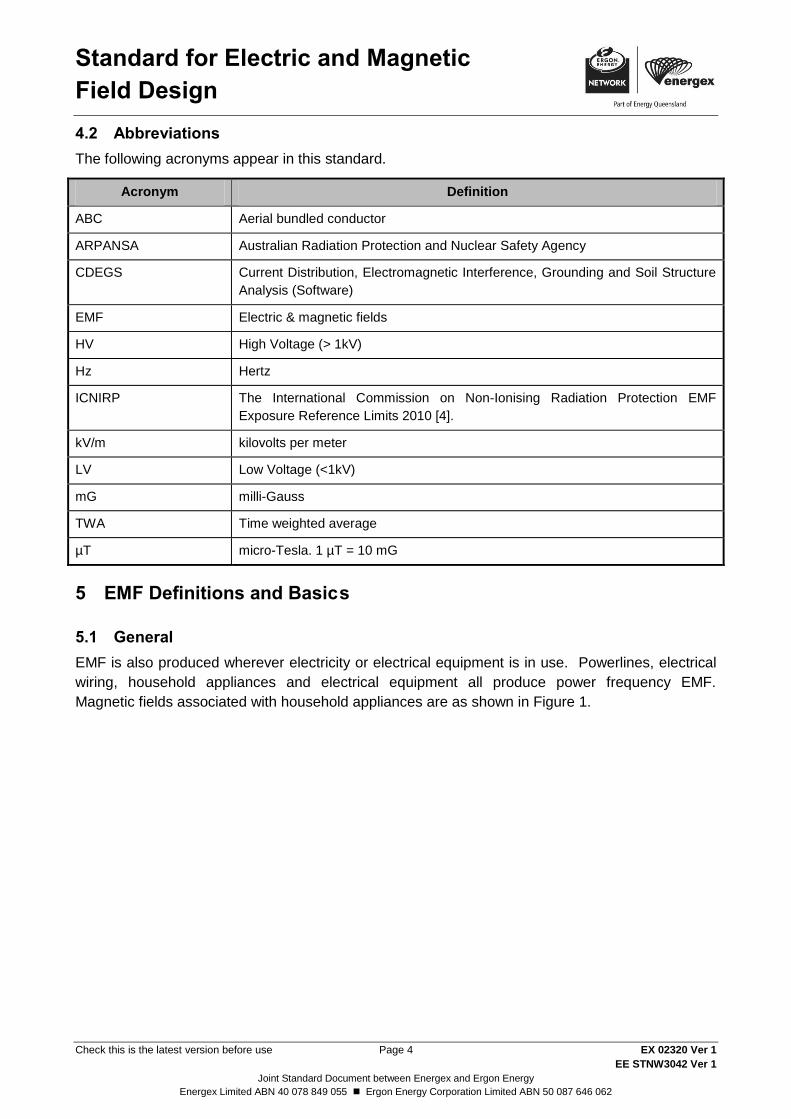
4.2 Abbreviations
The following acronyms appear in this standard.
Acronym Definition
ABC Aerial bundled conductor
ARPANSA Australian Radiation Protection and Nuclear Safety Agency
CDEGS Current Distribution, Electromagnetic Interference, Grounding and Soil Structure
Analysis (Software)
EMF Electric & magnetic fields
HV High Voltage (> 1kV)
Hz Hertz
ICNIRP The International Commission on Non-Ionising Radiation Protection EMF
Exposure Reference Limits 2010 [4].
kV/m kilovolts per meter
LV Low Voltage (<1kV)
mG milli-Gauss
TWA Time weighted average
µT micro-Tesla. 1 µT = 10 mG
5 EMF Definitions and Basic s
5.1 General
EMF is also produced wherever electricity or electrical equipment is in use. Powerlines, electrical
wiring, household appliances and electrical equipment all produce power frequency EMF.
Magnetic fields associated with household appliances are as shown in Figure 1.

Standard for Electric and Magnetic
Field Design
Check this is the latest version before use Page 5 EX 02320 Ver 1
EE STNW3042 Ver 1
Joint Standard Document between Energex and Ergon Energy
Energex Limited ABN 40 078 849 055 Ergon Energy Corporation Limited ABN 50 087 646 062
Figure 1 - Typical Magnetic Fields Around Household Appliances
5.2 Electric Fields
An electric field is proportional to the voltage, which remains constant as long as the equipment is
energised. The higher the voltage is, the higher the electric field. Electric fields are shielded by
most objects, including trees, buildings and human skin. For this reason, there are negligible
electric fields above high voltage screened underground cables.
The typical unit of measure is volts/metre (V/m or kV/m).
5.3 Magnetic Fields
A magnetic field is an invisible force that is produced by the flow (current) of electricity through a
wire. This effect is known as electromagnetism and magnetic fields are only present when the
power is on and a current is flowing. The strength of a magnetic field depends on the magnitude of
the current (Amps).
Field strength rapidly reduces as distance from the source of the current increases. The standard
unit for measurement is the Tesla, however magnetic fields from normal electricity use are much
smaller than the Tesla and the milligauss (mG) is common. A milligauss is 10 million times smaller
than a Tesla.

Standard for Electric and Magnetic
Field Design
Check this is the latest version before use Page 6 EX 02320 Ver 1
EE STNW3042 Ver 1
Joint Standard Document between Energex and Ergon Energy
Energex Limited ABN 40 078 849 055 Ergon Energy Corporation Limited ABN 50 087 646 062
5.4 How does EMF decrease with distance?
EMF decreases with distance from the source. Generally, at a distance from the source, the fields
will decrease as follows:
Single-phase current – 1/d,
Single circuit or double circuit un-transposed – 1/d2, and
Double circuit transposed (assuming symmetrical geometry) or coil – 1/d3.
In practice, factors such as unequal currents, zero sequence currents, tapered towers, geometrical
deviations on the structure, and very close proximity to sources will result in rates of decrease
which are less than the above. Furthermore, magnetic field profiles are typically shown
horizontally along the ground (at one metre above ground), perpendicular to the conductor and
typically at midspan where the conductors are closest to the ground.
5.5 High fields around electricity distribution and transmission utility environments.
The magnitude of EMF produced by electrical equipment is dependent of the size of the source, its
configuration, the voltage and current, and proximity.
Examples of situations where magnetic fields may approach or in some cases exceed guidelines
limits (see Section 6.2) include working in close proximity to:
Air cored dry-type reactors (substation workers),
Busbars (substation workers),
Low voltage boards (substation workers),
Transformer secondary terminations (substation workers),
Cables carrying large currents especially in pits and tunnels (substation workers, jointers),
Conductors carrying large currents (line workers),
Tools and equipment with transformers and motors (all workers),
High current testing (testers),
Earthing conductors carrying large currents (substation workers),
Connections between alternating generators and substations (workers and sometimes
general public), and
Fault scenarios (all workers and general public).
Examples of situations where elevated electric fields may approach or in some cases exceed
guidelines limits (see Section 6.2) include:
Directly under 220 kV and greater overhead power transmission lines (general public),
Directly under substation busbars (substation workers),
Close proximity to series reactors (substation workers),
Close proximity to high voltage conductors (live line workers),
Live line working using hot stick techniques (live line workers), and
Energised tower climbing during maintenance inspections (tower workers).

Standard for Electric and Magnetic
Field Design
Check this is the latest version before use Page 7 EX 02320 Ver 1
EE STNW3042 Ver 1
Joint Standard Document between Energex and Ergon Energy
Energex Limited ABN 40 078 849 055 Ergon Energy Corporation Limited ABN 50 087 646 062
6 ARPANSA Guidelines and Recommended Exposure Limits
6.1 General
As a member of the Electricity Networks Association (ENA), Energy Queensland takes its guidance
on EMF from the ENA Policy on Electric & Magnetic Fields and associated resources. This
organisation provides up to date research from across the world and provides professional advice
to all Australian member utilities.
As part of the Health and Aging Portfolio, Australian Radiation Protection and Nuclear Safety
Agency (ARPANSA) is a Federal Government agency charged with the responsibility for protecting
the health and safety of people, and the environment, from EMF. It provides advice to the ENA on
these matters.
The two internationally recognised exposure guidelines are ICNIRP and IEEE.
International Commission on Non-Ionizing Radiation Protection (ICNIRP) 2010.
International Committee on Electromagnetic Safety, Institute of Electrical and Electronics
Engineers (IEEE) in the USA 2002.
ARPANSA’s advice is “The ICNIRP ELF guidelines are consistent with ARPANSA’s understanding
of the scientific basis for the protection of people from exposure to ELF EMF.”
6.2 Reference Levels
Table 1 ICNIRP 50Hz EMF Exposure Reference Limits (2010) summarises the EMF exposure
limits which are instantaneous maximum exposure level limits. Reference should be made to the
ICNIRP Guidelines or ENA EMF handbook for details.
Table 1 - ICNIRP 50Hz EMF Exposure Reference Limits (2010)
Electric field (kV/m) Magnetic field (mG)
OCCUPATIONAL
Whole working day
10
10,000
Short term _ _
For limbs _ _
GENERAL PUBLIC
Up to 24 hours/day
5
2,000
Few hours/day _ _
Extremities _ _
Note that these limits should be read in conjunction with Section 7 – Prudent Avoidance,
particularly in relation to:
A. Rooms in buildings (e.g. residences, public buildings, etc.) which are regularly occupied for
significant periods of time;

Standard for Electric and Magnetic
Field Design
Check this is the latest version before use Page 8 EX 02320 Ver 1
EE STNW3042 Ver 1
Joint Standard Document between Energex and Ergon Energy
Energex Limited ABN 40 078 849 055 Ergon Energy Corporation Limited ABN 50 087 646 062
B. Public or private children’s playgrounds which have been designated as such under town
planning schemes;
C. Location with special groups of people such as students in school, children in day-care and
kindergarten centres; and
D. Areas of undeveloped land where the forms of utilisation defined under A, B & C above are
likely to eventuate.
6.3 Assessing compliance with exposure limits for occupational hazards
In general, electric and magnetic fields from electricity assets will be well below the Reference
Levels in these guidelines and specific compliance assessments will not be required. Exceptions
could include specific occupational activities in close proximity to assets such as very highly loaded
conductors, air cored reactors or air cored transformers.
The recommended process for assessing compliance with exposure limits is as per Figure 2
Figure 2 - Process for Assessing Compliance With Exposure Limits (Ref ENA EMF Handbook 2016 Fig 6.1)
6.4 Other lawful directions
Other external limits may be imposed on Energy Queensland network assets as a result of:
Court orders
Building approvals
Other lawfully agreed mediation outcomes/directions.
Standard for Electric and Magnetic
Field Design
Check this is the latest version before use Page 9 EX 02320 Ver 1
EE STNW3042 Ver 1
Joint Standard Document between Energex and Ergon Energy
Energex Limited ABN 40 078 849 055 Ergon Energy Corporation Limited ABN 50 087 646 062
7 Prudent Avoidance and Precautionary Assessment
7.1 General
The concept of prudent avoidance was first suggested in 1989 by Professor M. Grainger Morgan
(USA) as a sensible response to community concern regarding health aspects of EMF in the face
of ongoing scientific uncertainty. Sir Harry Gibbs also addressed this uncertainty in relation to
exposure to EMFs in a wide ranging inquiry into community needs and high voltage transmission
line development in Australia. In his March 1991 Report he said:
“It has not been established that electric fields or magnetic fields of power frequency are harmful to
human health but, since there is some evidence that they may do harm, a policy of prudent
avoidance is recommended.”
Since 1991, a succession of major inquiries including a further two in Australia have recommended
prudent avoidance, but the term has not been, and by its nature, cannot be defined with precision.
Prudent avoidance involves taking reasonable steps in any particular circumstance, and although a
precise definition cannot be given, it is possible to provide general guidance. The aim of this
section is to outline a range of options which may be applied in the context of prudent avoidance
for transmission and distribution situations. It remains the responsibility of the designers to apply
the principles appropriately to particular situations.
The Energy Networks Association of Australia has recommended to its members that a policy of
prudence (incorporating prudent avoidance) be applied in relation to EMF from supply industry
assets.
Energy Queensland has adopted this policy for the design, construction and operation of its
facilities.
Although useful, the above description is open to interpretation, especially in respect of the
question as to what might constitute “modest cost”. In this regard, in 1993, the California Public
Utilities Commission in the United States of America published an order defining prudent
avoidance as undertaking suitable activities up to 4% of the cost of a new electricity company
installation project.
In a document produced by Southern California Edison Company in 1994, design guidelines were
developed to “Implement no-cost and low-cost methods to reduce magnetic fields from new electric
utility facilities.”
The application of prudent avoidance in the design and construction of new electrical facilities is a
process of assessing the extent to which people may be exposed to fields produced by them and
considering what “low cost” and “no cost” measures might be taken to reduce such exposure within
acceptable constraints. It is considered that the 4% limit adopted by the California Public Utilities
Commission is appropriate and, accordingly it is suggested that, in the Energy Queensland
context, “modest cost” or “low cost” measures should be interpreted as involving up to 4% of the
total project cost.
Section 9 describes a number of specific options for prudent avoidance which may be applied to
transmission facilities.

Standard for Electric and Magnetic
Field Design
Check this is the latest version before use Page 10 EX 02320 Ver 1
EE STNW3042 Ver 1
Joint Standard Document between Energex and Ergon Energy
Energex Limited ABN 40 078 849 055 Ergon Energy Corporation Limited ABN 50 087 646 062
7.2 Precautionary Assessment
The focus of an exposure assessment should be on determining whether there are no cost and
low-cost measures that reduce exposure while not unduly compromising other issues. As there is
no scientific basis for specific targets, specific calculations of field levels will not always be
necessary.
If the average exposure is determined to be less than or equal to typical background magnetic field
levels, then any further reductions will not materially change the overall exposure and further
assessment would not be required.
Boundary for assessment 7.2.1
As the epidemiological studies typically use exposure within the home (often a child’s bedroom),
and in the absence of data suggesting otherwise, a conservative approach for residential areas is
to select the reference point as being the nearest part of any habitable room from the source and
at one metre above ground level. There may be specific circumstances that justify alternative
methods.
Loading calculations for magnetic fields 7.2.2
With precaution assessments, demonstrating that consideration has been given to low cost ways
to reduce exposure is more relevant than the highest predicted magnetic fields (as would otherwise
be the case for exposure limit assessments – see Section 6.3). Where specific calculations are
required the use of Time Weighted Average (TWA) loads is suggested as a reasonable approach.
This approach is supported by WHO that advise:
“In the absence of a known biophysical mechanism, which would yield a known etiologically
relevant metric of exposure, the metric of choice used in most epidemiological studies has been
the time weighted average.” [B33], pg. 275.
While loads of substations and powerlines will generally increase over time after commissioning, a
conservative approach which considers daily and seasonal variations, would be to calculate the
TWA over a complete year using loads shortly after commissioning and also in the year
representing the maximum foreseeable projected TWA.
Where available loading information does not permit the calculation of TWA, it may be necessary
to exercise judgement, based on the best available information to derive a typical load that will
occur on a line for the largest portion of a year which represents at least a conservative
approximation of TWA.
In the absence of any current information at all, the maximum magnetic field (Bmax) shall be
calculated for worst case normal conditions using a circuit loading of:
25% of summer noon emergency rating for a conductor for ring feed arrangements in
domestic and mixed load areas
50% of summer noon emergency rating for a conductor for ring feed arrangements in
industrial areas or continuous loads
100% of normal rating for radial supply arrangements.

Standard for Electric and Magnetic
Field Design
Check this is the latest version before use Page 11 EX 02320 Ver 1
EE STNW3042 Ver 1
Joint Standard Document between Energex and Ergon Energy
Energex Limited ABN 40 078 849 055 Ergon Energy Corporation Limited ABN 50 087 646 062
8 Calculators & Design Tools
EMF modelling shall be undertaken when transmission lines and substations are in close proximity
to sensitive areas as defined in Section 6.2.
8.1 Transmission – Overhead
For overhead applications with simple geometries and parallel conductors, the Ergon Energy EMF
calculator – 2D model can be used.
Where geometries are not parallel – the same calculator using the 3D model shall be used.
8.2 Transmission – Underground
For simple geometry underground transmission circuits with single point bonded sheaths only,
the 2D version of the Ergon Energy EMF calculator for magnetic fields can be used with reference
to the phase conductors only. Note that if the sheaths are cross bonded or bonded at both ends,
currents may be induced in the cable sheath that oppose those generated by the phase
conductors, so any calculations using this 2D model would be overly conservative.
In these cases, Cymecap has a module for calculation of EMF taking account of shielding from the
cable screens.
8.3 Distribution
Annex A 12Annex A gives field profiles for some standard overhead and underground distribution
geometries. Where overhead lines run parallel for extended lengths, the Ergon Energy EMF
calculator – 2D model can be used.
8.4 Zone Substations
The CDEGS – HIFREQ Engineering Module can give magnetic field profiles around a substation
based on complex cable locations and geometries.
9 General design requirements for prudent avoidance
9.1 Transmission – Overhead
Distance 9.1.1
The most common method of reducing EMF exposure is by selecting line routes (i.e. siting) to
avoid population centres or areas where people congregate. Particular attention should be paid to
Sensitive Areas.
Although a matter for developers/planning authorities, increased separation also needs to be
considered when new residential development is proposed adjacent to existing transmission lines.
This could involve either the sacrificing of land within the development site or the relocation of
some parts of the line.

Standard for Electric and Magnetic
Field Design
Check this is the latest version before use Page 12 EX 02320 Ver 1
EE STNW3042 Ver 1
Joint Standard Document between Energex and Ergon Energy
Energex Limited ABN 40 078 849 055 Ergon Energy Corporation Limited ABN 50 087 646 062
Figure 3 illustrates how magnetic field strength reduces with distance from the line. Raising the
height of the supporting structures or towers, and thus the height of the conductors, can also
reduce the magnetic field strength below the line. However, the cost and visual impact associated
with the increased structure height may limit this technique to selected portions of a line. Structure
raising may be more practical for wood pole lines than for steel tower lines, due to the cost factor.
Figure 3 - Magnetic Field as Function of Power Line Geometry
Conductor Configuration/Line Compaction 9.1.2
Different arrangements of phasing can produce different magnetic field strengths for the same line current. In general, triangular arrangements tend to provide more field cancellation than horizontal arrangements, with lower resultant field strengths. The effect of line geometry on magnetic field profile for a typical transmission line is shown in Figure 3.
Line compaction can also reduce the resultant EMF by enhancing the field cancellation effect between the phases. Although the ability to achieve compaction is limited by factors relating to the electrical performance of the line, it can be an attractive option as compact lines offer some other advantages. These include reduced visual impact and reduced easement width.
Phase Arrangements 9.1.3
For double circuit lines, it is possible to arrange each 3-phase circuit with a different vertical phase arrangement in space, such that some cancellation of magnetic fields occurs. Adoption of low reactance (RWB/BWR) phasing when current flow in both circuits is in the same direction results in the lowest magnetic fields. This is usually a relatively low cost option in the case of an existing line, and often a no cost option for a new line.
Selection of the proper phasing arrangement is usually the most effective way to reduce magnetic fields for two circuits on the same structure or two or more circuits on the same easement for minimal cost, if re-routing is not possible.
Split Phasing 9.1.4
A single circuit line can be constructed as two parallel circuits with a phase arrangement designed to achieve maximum field cancellation. This is known as the split-phase technique and may be considered if only one circuit exists on a route. Although this form of construction is significantly more expensive than conventional single-circuit construction, it could be used for short sections of a line where it is desired to reduce fields.
0
2
4
6
8
10
12
14-5
0
-40
-30
-20
-10 0
10
20
30
40
50
Distance in metres
Mil
liG
au
ss
pe
r 1
00 A
mp
s
1
2
3
4
Typical magnetic field profile at 1 m above ground for overhead transmission line.
1. Single circuit with horizontal flat configuration of phases
2. Single circuit with triangular configuration of phases
3. Single circuit with vertical configuration of phases
4. Double circuit with vertical configuration of phases and with favourable phase sequence.
Figure 3.1 Magnetic Field as Function of Power Line Geometry

Standard for Electric and Magnetic
Field Design
Check this is the latest version before use Page 13 EX 02320 Ver 1
EE STNW3042 Ver 1
Joint Standard Document between Energex and Ergon Energy
Energex Limited ABN 40 078 849 055 Ergon Energy Corporation Limited ABN 50 087 646 062
Fourth Wire Scheme 9.1.5
A significant field reduction can be obtained with a relatively simple arrangement consisting of splitting one of the phases in two and placing this fourth line in a strategic location as shown below.
The current in phase A is split into two wires. The impedance of the two wires and the mutual inductances with the other two phases determine the current split. This scheme can reduce the magnetic field by a factor of 2 or more by proper selection of the size and characteristics of the fourth wire. The scheme can be applied to an existing line and to a few spans only, when the field reduction is only locally required.
If in addition to a fourth wire a series capacitor is added in series with this wire, greater field reduction can be achieved. The circulating current in the loop formed by phase A and the fourth wire can be adjusted by a proper choice of capacitor value. This circulating current will partially cancel the field caused by the other two phases. The capacitor must be designed to withstand line current and voltage.
Transposition 9.1.6
This method of field reduction consists of transposing the phase from one structure to the next. This type of transposition can be applied to single circuit delta configuration and some types of split phase lines to obtain a field reduction. This method brings the conductors closer at mid-span. A spacer is not required unless dictated by mechanical issues.
Current Reduction 9.1.7
A reduction in current will generally reduce magnetic field strengths. The reduction in field strength is approximately proportional to the reduction in current. For a given load transfer requirement, the only way to reduce the current is to increase the voltage. However, because cost is related to line voltage, increasing line voltage will likely result in substantial extra cost and other design options are likely to be preferable.
Shielding and Cancellation Loops 9.1.8
Shielding is the erection of a barrier between an EMF source and a subject to reduce the field strength at the subject. A simple shielding barrier can substantially reduce electric fields from transmission lines but has little effect on magnetic fields. Any object between the source (line) and the point of interest will provide shielding or distortion of the electric field. Common examples are buildings, trees or any other structure.
For all practical purposes there are no means to significantly reduce or screen magnetic fields from overhead lines. In special applications, screening of individual pieces of equipment is possible, using structures or enclosures made from special metals.
“Cancellation” or “Degaussing” loops are conducting wires suspended between adjacent structures, above or below the phase conductors to provide both shielding and cancellation effects. They may be either “active” (energised) or “passive” (non-energised) and rely on a current flow in the opposite direction to cancel or reduce the overall field produced by the line. The use of shielding or cancellation loops is regarded as complex and requires specialist knowledge. Any cases requiring this option should be referred to the Group Environment Manager.
9.2 Transmission – Underground
Under grounding is usually far more expensive than overhead construction. However, there will be occasions when partial under grounding may be required.
A B C A’
Standard for Electric and Magnetic
Field Design
Check this is the latest version before use Page 14 EX 02320 Ver 1
EE STNW3042 Ver 1
Joint Standard Document between Energex and Ergon Energy
Energex Limited ABN 40 078 849 055 Ergon Energy Corporation Limited ABN 50 087 646 062
The factors that affect the magnetic field produced by underground cable systems may be grouped into four categories:
System grounding;
Currents in cables;
Installation factors; and
Cable construction.
System Grounding 9.2.1
The three types of commonly used grounding are single-point grounding, multi-point grounding and cross-bonded sheath grounding.
Single-point grounded cables eliminate induced sheath currents. However, significant steady state and transient voltages which create a safety hazard, can be induced in the cable sheaths. For this case, sheath voltage limiters should be used to limit voltage.
In multi-point grounded cable systems, the cable sheath is grounded at two or more points to maintain the cable sheaths at or very close to ground potential. The magnetic flux produced by the currents in the conductors induces currents in the cable sheaths with two significant results. First, the induced sheath currents increase losses and heating in the cable system which in turn reduces the current carrying capacity of the cables. The second effect is the induced currents produce a magnetic field opposing the fields produced by the phase conductors, causing a reduction in the magnetic field outside the cable. The induced current in the sheaths can be comparable in magnitude to the current in the cable cores. For this situation the current rating of the cable is substantially affected and hence is unacceptable in practice.
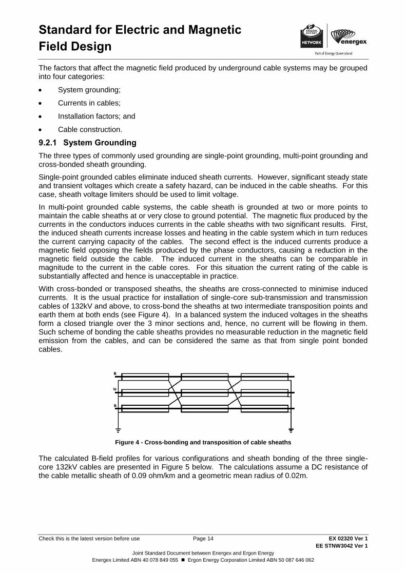
With cross-bonded or transposed sheaths, the sheaths are cross-connected to minimise induced currents. It is the usual practice for installation of single-core sub-transmission and transmission cables of 132kV and above, to cross-bond the sheaths at two intermediate transposition points and earth them at both ends (see Figure 4). In a balanced system the induced voltages in the sheaths form a closed triangle over the 3 minor sections and, hence, no current will be flowing in them. Such scheme of bonding the cable sheaths provides no measurable reduction in the magnetic field emission from the cables, and can be considered the same as that from single point bonded cables.
Figure 4 - Cross-bonding and transposition of cable sheaths
The calculated B-field profiles for various configurations and sheath bonding of the three single-core 132kV cables are presented in Figure 5 below. The calculations assume a DC resistance of the cable metallic sheath of 0.09 ohm/km and a geometric mean radius of 0.02m.

Standard for Electric and Magnetic
Field Design
Check this is the latest version before use Page 15 EX 02320 Ver 1
EE STNW3042 Ver 1
Joint Standard Document between Energex and Ergon Energy
Energex Limited ABN 40 078 849 055 Ergon Energy Corporation Limited ABN 50 087 646 062
Spaced Flat (SPG)
Spaced Flat (MPG)
Flat Touching (SPG)
Flat Touching (MPG)
Trefoil (SPG)
Trefoil (MPG)
Spaced Flat (SPG)
Spaced Flat (MPG)
Flat Touching (SPG)
Flat Touching (MPG)
Trefoil (SPG)
Trefoil (MPG)
Figure 5 - Magnetic Field as function of circuit configuration and bonding system-(Unshielded circuit. Field
calculated at 1m above ground and balanced current @ 640 A/phase)
Any form of passive electromagnetic shielding of cables, when the shield is made of ferromagnetic metal and is placed physically close to the cable, will result in reduction of the current rating of the cables. This is due to heat dissipation in the shield as a result of flow of induced eddy current and the effect of skin depth.
Cable currents 9.2.2
The amount of zero sequence or unbalance current flowing in a conductor has a significant impact on the magnitude of the magnetic field and how it decays with distance. The field decays by the reciprocal of distance rather than reciprocal of square of distance as for positive sequence currents.
Installation factors 9.2.3
In underground cables, phase conductors are insulated from earth and from each other by a relatively thin layer of solid insulation, as compared to a much larger dimension of air insulation in the case of overhead lines. Accordingly, underground phase conductors can be placed much closer together, providing a significant decrease in magnetic field as you move away from the centreline.
However, underground cables are normally buried 1 metre or less below ground and can be closer to people than an equivalent overhead line. Nevertheless, due to the cancellation effect, the use of underground cables usually reduces the effective level of the magnetic field. An exception to this might be the situation of cables in a street where the area of concern regarding exposure may be the footpath or roadway immediately above the buried cable where the field strength is still significant.
Typical circuit configurations are:
Flat (spaced or touching)
Trefoil (spaced or touching)
Reduced phase spacing increases the mutual heating between the cables and increasing the depth of burial increases the thermal resistance that losses must flow through to get to the surface of the earth. Both these approaches will derate the cables.
Standard for Electric and Magnetic
Field Design
Check this is the latest version before use Page 16 EX 02320 Ver 1
EE STNW3042 Ver 1
Joint Standard Document between Energex and Ergon Energy
Energex Limited ABN 40 078 849 055 Ergon Energy Corporation Limited ABN 50 087 646 062
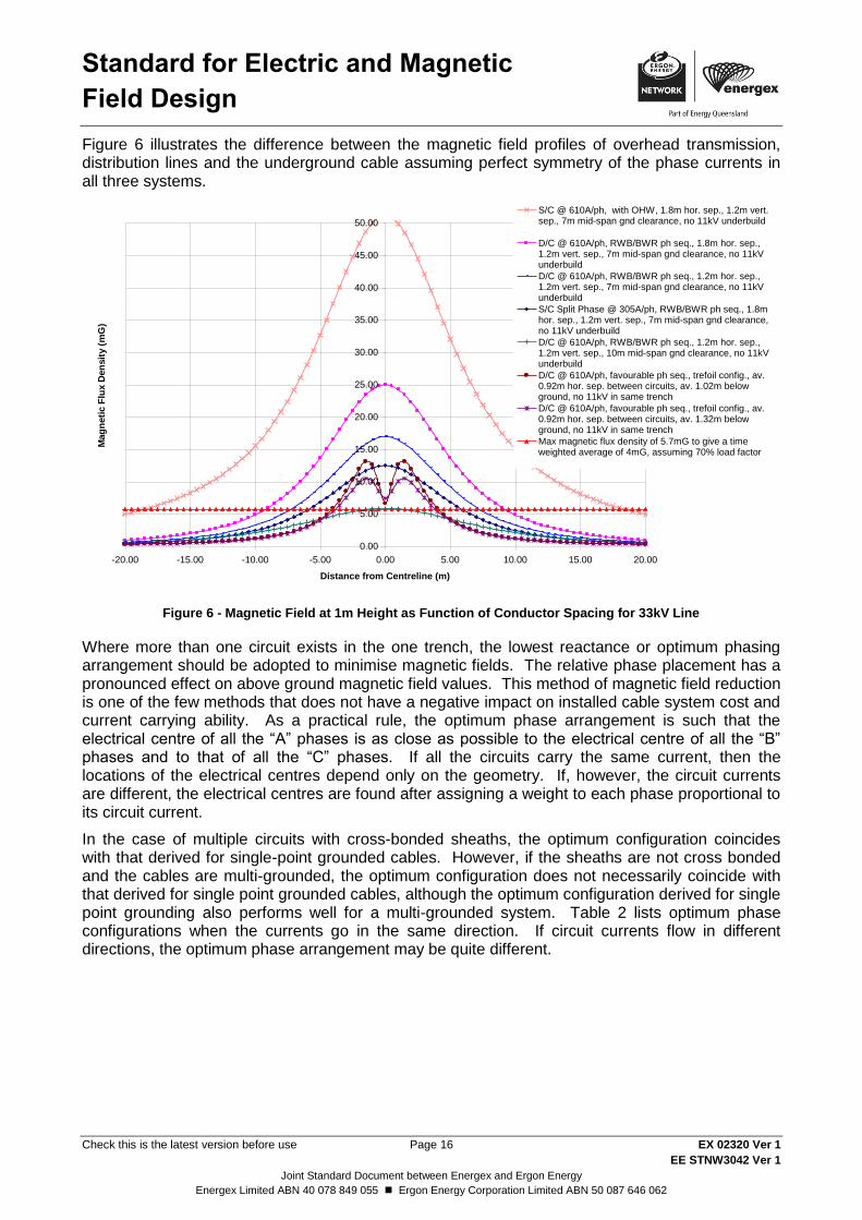
Figure 6 illustrates the difference between the magnetic field profiles of overhead transmission, distribution lines and the underground cable assuming perfect symmetry of the phase currents in all three systems.
Figure 6 - Magnetic Field at 1m Height as Function of Conductor Spacing for 33kV Line
Where more than one circuit exists in the one trench, the lowest reactance or optimum phasing arrangement should be adopted to minimise magnetic fields. The relative phase placement has a pronounced effect on above ground magnetic field values. This method of magnetic field reduction is one of the few methods that does not have a negative impact on installed cable system cost and current carrying ability. As a practical rule, the optimum phase arrangement is such that the electrical centre of all the “A” phases is as close as possible to the electrical centre of all the “B” phases and to that of all the “C” phases. If all the circuits carry the same current, then the locations of the electrical centres depend only on the geometry. If, however, the circuit currents are different, the electrical centres are found after assigning a weight to each phase proportional to its circuit current.
In the case of multiple circuits with cross-bonded sheaths, the optimum configuration coincides with that derived for single-point grounded cables. However, if the sheaths are not cross bonded and the cables are multi-grounded, the optimum configuration does not necessarily coincide with that derived for single point grounded cables, although the optimum configuration derived for single point grounding also performs well for a multi-grounded system. Table 2 lists optimum phase configurations when the currents go in the same direction. If circuit currents flow in different directions, the optimum phase arrangement may be quite different.
Figure 3.4 MAGNETIC FIELD at 1m Height as Function of Conductor Spacing for 33kV Line
0.00
5.00
10.00
15.00
20.00
25.00
30.00
35.00
40.00
45.00
50.00
-20.00 -15.00 -10.00 -5.00 0.00 5.00 10.00 15.00 20.00
Distance from Centreline (m)
Mag
neti
c F
lux D
en
sit
y (
mG
)
S/C @ 610A/ph, with OHW, 1.8m hor. sep., 1.2m vert.sep., 7m mid-span gnd clearance, no 11kV underbuild
D/C @ 610A/ph, RWB/BWR ph seq., 1.8m hor. sep.,1.2m vert. sep., 7m mid-span gnd clearance, no 11kVunderbuild
D/C @ 610A/ph, RWB/BWR ph seq., 1.2m hor. sep.,1.2m vert. sep., 7m mid-span gnd clearance, no 11kVunderbuild
S/C Split Phase @ 305A/ph, RWB/BWR ph seq., 1.8mhor. sep., 1.2m vert. sep., 7m mid-span gnd clearance,no 11kV underbuild
D/C @ 610A/ph, RWB/BWR ph seq., 1.2m hor. sep.,1.2m vert. sep., 10m mid-span gnd clearance, no 11kVunderbuild
D/C @ 610A/ph, favourable ph seq., trefoil config., av.0.92m hor. sep. between circuits, av. 1.02m belowground, no 11kV in same trench
D/C @ 610A/ph, favourable ph seq., trefoil config., av.0.92m hor. sep. between circuits, av. 1.32m belowground, no 11kV in same trench
Max magnetic flux density of 5.7mG to give a timeweighted average of 4mG, assuming 70% load factor
Standard for Electric and Magnetic
Field Design
Check this is the latest version before use Page 17 EX 02320 Ver 1
EE STNW3042 Ver 1
Joint Standard Document between Energex and Ergon Energy
Energex Limited ABN 40 078 849 055 Ergon Energy Corporation Limited ABN 50 087 646 062
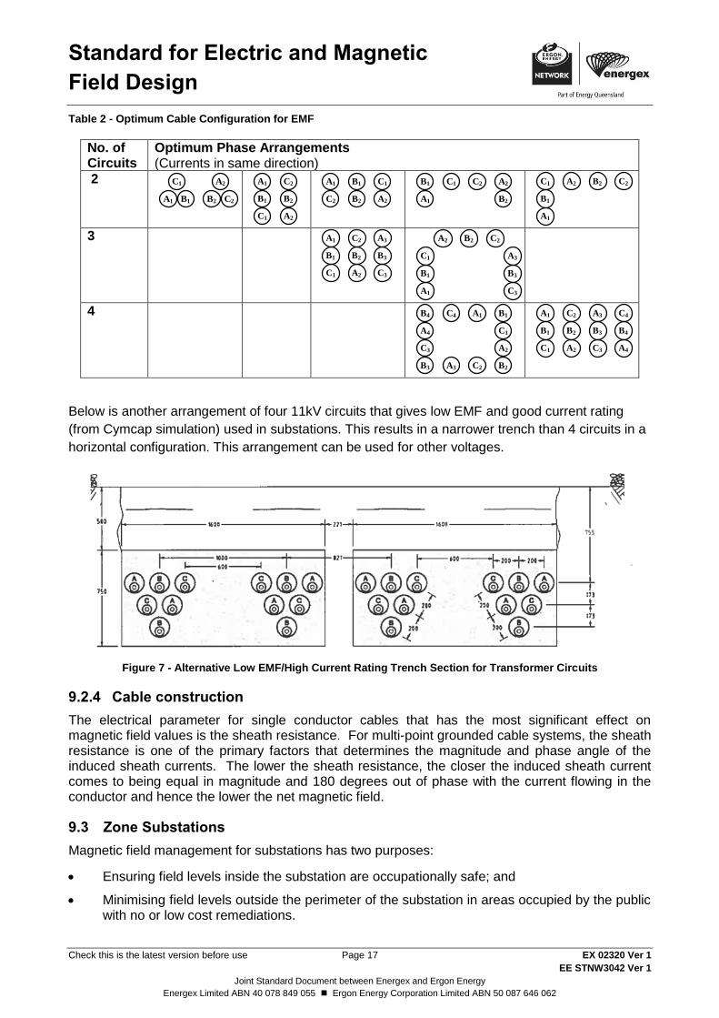
Table 2 - Optimum Cable Configuration for EMF
No. of Circuits
Optimum Phase Arrangements (Currents in same direction)
2
3
4
Below is another arrangement of four 11kV circuits that gives low EMF and good current rating
(from Cymcap simulation) used in substations. This results in a narrower trench than 4 circuits in a
horizontal configuration. This arrangement can be used for other voltages.
Figure 7 - Alternative Low EMF/High Current Rating Trench Section for Transformer Circuits
Cable construction 9.2.4
The electrical parameter for single conductor cables that has the most significant effect on magnetic field values is the sheath resistance. For multi-point grounded cable systems, the sheath resistance is one of the primary factors that determines the magnitude and phase angle of the induced sheath currents. The lower the sheath resistance, the closer the induced sheath current comes to being equal in magnitude and 180 degrees out of phase with the current flowing in the conductor and hence the lower the net magnetic field.
9.3 Zone Substations
Magnetic field management for substations has two purposes:
Ensuring field levels inside the substation are occupationally safe; and
Minimising field levels outside the perimeter of the substation in areas occupied by the public with no or low cost remediations.
A1 B1
C1 A2
B2 C2
A1
B1
C1 A2
B2
C2 A1 B1 C1
A2B2C2 A1
B1 C1 A2
B2
C2
A1
B1
C1 A2 B2 C2
A1
B1
C1 A2
B2
C2 A3
B3
C3
A1
B1
C1
A2 B2 C2
A3
B3
C3
A1 B1
C1
A2
B2C2A3B3
C3
A4
B4 C4 A1
B1
C1 A2
B2
C2 A3
B3
C3 A4
B4
C4

Standard for Electric and Magnetic
Field Design
Check this is the latest version before use Page 18 EX 02320 Ver 1
EE STNW3042 Ver 1
Joint Standard Document between Energex and Ergon Energy
Energex Limited ABN 40 078 849 055 Ergon Energy Corporation Limited ABN 50 087 646 062
There are a number of EMF sources within a substation. Sources to take particular account of in and around substations include:
Bus arrangement;
Air-cored reactors; and
Transmission and distribution lines entering and exiting the substation.
High current cables, such as the cabling from transformer LV windings.
Siting of the substation, or even fencing of the substation equipment (often part of the whole site) to minimise magnetic field strengths in areas accessible to the public should be carried out to meet the requirements of Table 1.
Bus Arrangement 9.3.1
Major sources of magnetic fields inside and outside a substation are the buses connected with the low voltage side of transformers. These buses carry the largest loads and may be placed, because of lower voltages, closer to ground or walls.
Options for reducing magnetic fields include:
Increase distances to ground/wall/ceiling depending on the situation,
Favourable phasing of adjacent buses,
Reduce phase-to-phase spacing (phase compaction),
Split phase buses,
Application of cancellation loops,
Shielding of adjacent rooms,
Metal enclosure of busbars and switchgear.
Air-cored Reactors 9.3.2
Air-cored reactors should be installed with careful consideration of their placement in the substation and assessment of the most optimal physical arrangement of the reactor coils in respect to the EMF emission. Where magnetic field levels have the potential to exceed the occupational level of 5,000mG at the fence enclosure, suitable warning signs should be placed alerting staff they are approaching areas with strong EMF.
Line Entrance into Substations 9.3.3
The options detailed in 9.1 and 9.2 should be taken into account for outgoing and incoming overhead and underground transmission lines, especially where they come together at entries to busbar arrangements. Particular opportunities may arise where multiple circuits parallel one another as they converge on the substation. Other techniques to consider include:
Siting of substations taking into account the types of land uses adjacent to substations;
Managing access by minimising public usage around the substations;
Locating sources as far from the fence line or substation walls as possible;
Increasing the property area and creating open buffer areas around the substation;
Optimising phasing and geometry, particularly increasing the height of overhead lines entering the substation;
Compacting lines; and
Standard for Electric and Magnetic
Field Design
Check this is the latest version before use Page 19 EX 02320 Ver 1
EE STNW3042 Ver 1
Joint Standard Document between Energex and Ergon Energy
Energex Limited ABN 40 078 849 055 Ergon Energy Corporation Limited ABN 50 087 646 062
Transitioning from a line with vertical configuration to a split-phase line at the substation entrance.
Magnetic fields of underground cables at the substation entrance may be minimised by taking the following techniques into account:
Trefoil configuration instead of flat
Optimising cable position and phasing;
Increasing cable depth for the initial section of cables;
Placing steel plates, either flat or shaped like an inverted U over the cables; and
Bonding of cable sheaths at both ends of the initial section of cables.
Land Development 9.3.4
Land development adjacent to transmission and sub-transmission lines often occurs after the line
has been built. The prospect of future land subdivision and development may create an argument
for adopting wider easements in order to meet the requirements of Table 1.
9.4 Distribution Lines
Siting 9.4.1
Due to the need to provide supply to customers, the options available in siting distribution infrastructure are limited. Distribution lines, by their very nature and function are normally located in road reserves to provide supply to customers on both sides of the road, although in some instances, they are located at the rear boundary of residential properties.
Where practicable:
Distribution lines should be located on the opposite side of the road from Sensitive Areas;
Distribution lines should be sited away from the walls of multi-storey buildings or areas where children congregate;
Distribution lines should be located on the side of the road bordered by open spaces where applicable; and
Substations should be located at the electrical centre of their low voltage network, i.e. current flows in all directions should be balanced.
Design 9.4.2
Design options include:
Use of aerial bundled conductor (ABC) for low voltage reticulation to provide more effective field cancellation;
Use of offset construction (i.e. with all phases constructed on the same side of the pole) to increase horizontal separation from the point of interest;
Use of underground cable in place of overhead conductors where economically justified;
Use of three phase cable instead of 3 single phase cables;
Balancing of load across all phases to reduce neutral currents;
Use of insulated twisted service cable instead of open wire services to provide more effective field cancellation. Open wire services are a non-standard installation and should be avoided where possible; and

Standard for Electric and Magnetic
Field Design
Check this is the latest version before use Page 20 EX 02320 Ver 1
EE STNW3042 Ver 1
Joint Standard Document between Energex and Ergon Energy
Energex Limited ABN 40 078 849 055 Ergon Energy Corporation Limited ABN 50 087 646 062
For new double circuit lines, adoption of low reactance (RWB/BWR) phasing when current flow in both circuits is in the same direction.
When installing infrastructure which involve both low voltage and high voltage, the following options apply:
When overbuilding (or under building) existing facilities, the phasing on the existing circuits should be determined and the new circuit or circuits phased to minimise the combined magnetic field strength.
Where new or reworked sub transmission facilities are being considered on the same structure with distribution circuits, the most effective field reduction measures may be applied to the distribution circuits.
Summary of Magnetic Field Management Options for Distribution Lines 9.4.3
9.4.3.1 Distribution HV
Change existing cross-arm configurations into compact delta or ABC;
Use post insulators for delta or compact vertical;
Reduce line currents by increasing the distribution line primary voltage;
Increase distribution line pole height;
Optimise phasing of multiple circuit lines;
Use a split-phase design; and
Use underground where practical and feasible.
9.4.3.2 LV and Service Drops
Balance the loads of the three phases;
Overhead: Use ABC rather than open wire LV and service drops; and
Underground: No change in existing practices.
9.4.3.3 Residential and Grounding System
Place distribution transformers at the centre of the services;
Locate and repair broken or bad service neutrals;
9.4.3.4 Bad Practice or What Not to Do
The following is a list of distribution practices which can generate levels of magnetic fields that may cause reference guidelines to be exceeded and should be avoided in sensitive locations as defined by "Special Conditions" in Section 6
Don’t install 3-phase single-core cables with large spacing between cores;
Avoid installing LV underground cable close to the sides of buildings by renegotiating wider alignment widths with local government where possible;
Don’t install ABC on building facades;
Don’t use the same phase sequence on double circuit power lines suspended on the same support structures;
Optimise distribution design to use no larger than 315kVA distribution transformers on pole tops except where required for major customers, in which case the LV run should be kept short;
Standard for Electric and Magnetic
Field Design
Check this is the latest version before use Page 21 EX 02320 Ver 1
EE STNW3042 Ver 1
Joint Standard Document between Energex and Ergon Energy
Energex Limited ABN 40 078 849 055 Ergon Energy Corporation Limited ABN 50 087 646 062
Don’t install open type overhead LV mains in build-up areas;
Don’t build heavy-current overhead power lines near Sensitive Areas;
Don’t give specific EMF advice regarding customer installations (refer to Customer Installations);
Don’t design LV switchboards with large separation distance between active and neutral busbars;
Don’t share one neutral cable between several different mains or sub-mains;
Don’t install energy meter panels or distribution boards backing into user sensitive areas such as bedrooms, etc.;
Don’t install a distribution transformer with its LV terminals facing user sensitive areas.
Don’t rely on passive shielding as the solution to all EMF problems; and
Don’t think that under grounding of power lines will necessarily solve EMF problems.
9.5 Distribution Substations
General Principles 9.5.1
Distribution and consumer substations are typically 22,000/400 V or 11,000/400 V and generally either pole mounted or ground mounted. Ground mounted substations may be installed in a padmount substation, in a separate outdoor fenced enclosure, or as part of a customer’s building.
The main sources of magnetic fields from distribution substations are the transformer bushings, the high voltage and low voltage cables and line connections, the associated switchgear and also the earth straps and neutrals when forming alternative paths to earth for unbalanced currents.
Underground metallic pipes and telecommunication cables with metallic screens, or even structural steel can also be significant sources of magnetic fields if they constitute a return path for a portion of the substation earth or neutral currents.
Due to the higher associated current levels, the low voltage side of a distribution substation has higher levels of magnetic field than the high voltage side.
Metal-clad substations, where mild steel is usually used for fabrication of enclosures, are afforded a modest level of shielding by the enclosure. Also, reinforced concrete slabs, walls and floor panels can provide some magnetic field shielding. However, it should be noted that, unless cables, busbars and the like are fully surrounded, any shielding afforded by metallic enclosures becomes less effective with increased distance from the source. Building materials such as brick, stone, plaster, wallboards and wood have no shielding properties for magnetic fields.
The following basic magnetic field management techniques can be applied in the design of substations:
Increasing the distance of magnetic field sources from the exposure area;
Reducing the conductor or busbar spacing;
Selecting an appropriate phase configuration; and
Balancing load between phases to reduce the neutral current.
Specific Measures 9.5.2
In designing distribution substations, the following design measures should be considered. Some measures are more appropriate for buildings, and some for outdoor substations near domestic dwellings.
In the case of buildings:

Standard for Electric and Magnetic
Field Design
Check this is the latest version before use Page 22 EX 02320 Ver 1
EE STNW3042 Ver 1
Joint Standard Document between Energex and Ergon Energy
Energex Limited ABN 40 078 849 055 Ergon Energy Corporation Limited ABN 50 087 646 062
Locating substations away from normally occupied areas such as offices, lunchrooms, etc.;
Planning the substation layout so that the low voltage side is further away from adjacent dwellings, offices, computer rooms, etc than the HV side.
Locating transformers, low voltage busbars, disconnector switches and other potentially large sources of magnetic field within the area of the substation as far away as possible from adjacent offices, etc.;
If the floor above the substation is used as residential office space, avoiding where possible, direct ceiling mounting of heavy current cables, open type busbars or disconnector switches. The converse applies if the floor below the substation is used as office or residential space;
Locating all cable trays as far as possible from the substation ceiling and walls that separate it from adjacent dwellings, offices, etc.;
Designing busbars to minimise separation between phases and between phases and the neutral bus;
If practicable, orienting transformers and other sources that have uneven field patterns so that their highest field strength side is turned away from the field sensitive area;
Where possible, using three phase or triplex HV cables in preference to three single phase cables;
Using a trefoil arrangement of cables when using three single core cables in a three phase configuration. In such cases, if the neutral conductor is a separate single core cable, placing it, where practicable, as close as possible to the centre of the trefoil formation of phases;
Selecting the substation equipment considering, among other important electrical parameters, its low magnetic field design, i.e. 11,000/400 V distribution transformers in steel housings, compact metal-clad busbars;
Avoiding phase by phase grouping of single core cables in parallel circuits;
Distributing all large single phase loads and all constant current load such as lighting and office equipment equally between three phases of the low voltage supply; and
In the case of outdoor substations:
Where possible, locate substations away from Sensitive Areas.
Maintain spacings for EMF as per Underground Construction Manual requirements.
Positioning the low voltage side of the transformer so that barriers such as landscaping, fencing or block walls inhibit normal access to that side of the substation.
9.6 Customer Installations
Sources within customers’ installations can also make a significant contribution to the overall
magnetic field environment. Whilst customer installations are generally not Energy Queensland’s
responsibility, considerations to be aware of are provided below.
Customers’ installations may require consideration of positioning of Energy Queensland assets
and customer assets. Energy Queensland assets should be positioned such that, as far as
practical, exposure is minimised particularly in Sensitive Areas. Whilst we do not provide any
advice to customers about the arrangement of their assets, our general advice is that customers
adopt a precautionary approach. It is the customers’ responsibility if they have concerns about the
health risks of magnetic fields, to decide how to address those concerns. Customers are
encouraged to obtain their own independent expert advice.

Standard for Electric and Magnetic
Field Design
Check this is the latest version before use Page 23 EX 02320 Ver 1
EE STNW3042 Ver 1
Joint Standard Document between Energex and Ergon Energy
Energex Limited ABN 40 078 849 055 Ergon Energy Corporation Limited ABN 50 087 646 062
The Queensland Government has developed guidelines to help manage potential risks associated
with magnetic fields in government office buildings; “Guidelines for the management of 50Hz
magnetic fields in office buildings” (PDF, 610KB).
Commercial/Industrial Switchboards 9.6.1
In the case of large commercial/industrial switchboards, the busbars inside the switchboard can have an effect on field levels outside the switchboard. The following measures should be taken into account:
Keeping the incoming line and associated meter panel and/or busbars away from frequented areas. This will also help avoid computer interference problems;
Avoiding the use of separate conductor trays for the energised and neutral wires. If separate trays are necessary, it is best to place them adjacent to low/no use areas;
Locating switchboards away from high use office areas if possible;
Locating workstations away from switchboards when laying out new or reorganised office areas.
Using energy efficient lift motors, air conditioning equipment and industrial motors and manufacturing equipment.
Domestic Meters and Wiring 9.6.2
Generally, the principal source of magnetic fields associated with domestic meter boxes is the wires leading to the meter box and the electricity meter. The following options are available:
In general, for new constructions, the layout of meters, switchboard and wiring may be planned in advance, giving consideration to the magnetic fields that they would produce.
Locating the meter box in an area that is not adjacent to high use areas. Good locations would be at the garage, a closet, storage room or at the back of a wardrobe. Bedroom and living room walls are better avoided to reduce fields in active use areas. Placement of meters and switchboard in a back-to-back arrangement is recommend, with meters outside and switchboard inside the home for security of home and occupants. This arrangement usually places the switchboard in low-use areas for the sake of appearance;
Locating the main connecting wiring away from high use areas in cases where meter location and switchboard location are separated by a significant distance, e.g. where meters are installed at the fence and the switchboard is located at (or in) the house. The connecting wiring should be run with phases and neutral grouped together, and in a ceiling space rather than a wall space, for example;
Using service wires of insulated twisted construction, as they produce significantly less fields than open wire (bare conductor) construction;
Minimising or avoiding situations where heavy current wiring, especially that of stoves and air-conditioning is placed in wall cavities within the house. This type of wiring is best located and grouped together in the ceiling. Close proximity of the phase wires and neutral helps to cancel the magnetic fields;
In the case of two-way switches, running the neutral wire along the same path as the twin active wire connecting the two switches to provide a cancelling effect on the magnetic fields; and
Using energy efficient equipment which will use less electricity and save money, as well as reducing the electrical load on the switchboard, thereby reducing magnetic fields. Large white goods such as refrigerators, dishwashers, washing machines and dryers are often sold with energy efficient model alternatives.

Standard for Electric and Magnetic
Field Design
Check this is the latest version before use Page 24 EX 02320 Ver 1
EE STNW3042 Ver 1
Joint Standard Document between Energex and Ergon Energy
Energex Limited ABN 40 078 849 055 Ergon Energy Corporation Limited ABN 50 087 646 062
10 Measurement Protocol
If measurements are to be taken of high field areas, it is required that:
A clear purpose and scope of the measurement program be prepared; and
Suitably trained personnel are used.
The measurements and their documentation should be undertaken in the following manner:
Use a suitable measurement standard (for example as the ANSI/IEEE standard 644-2019 "IEEE Standard procedures for measurement of Power Frequency Electric and Magnetic Fields from AC Power Lines");
Use of suitable measurement equipment such as the EMDEX II RMS power frequency magnetic field exposure meter and an AC RMS Electric Field Meter (such as Monroe Electronics Inc).
Set equipment at maximum current and normal voltage levels;
Take spot measurements to ascertain existence of high field areas;
Measurements should be representative of normal working conditions and thus should be taken at 0m, 1m and 2m heights for a standing person. If above ground access is possible then measurements should reflect possible access locations. The measurements do not represent whole body exposures;
For magnetic fields, measurements should be in a 1m grid around the equipment or in the area where a person may need to be located to operate or inspect a particular piece of apparatus; and
The following information should be documented and a copy forwarded onto the relevant Asset Standards Engineer.
- Measurement method used;
- Instruments used including calibration detail;
- Persons undertaking the measurement;
- Heights that measurements were taken;
- Diagram of measurement grid and equipment outline;
- Units of measurement;
- Date and time of measurement;
- Current flowing in equipment;
- Voltage level in equipment; and
- Results and report conclusions.
Form ES000904F101 shall be used to record EMF measurements.
11 Communication on EMF Enquiries
11.1 General Enquiries
General enquiries should be directed through the Contact Centre. Customer Interactions Officer to
identify the nature of the call and clarify the assets involved. If general information only is required
the following endorsed EMF information may be provided:

Standard for Electric and Magnetic
Field Design
Check this is the latest version before use Page 25 EX 02320 Ver 1
EE STNW3042 Ver 1
Joint Standard Document between Energex and Ergon Energy
Energex Limited ABN 40 078 849 055 Ergon Energy Corporation Limited ABN 50 087 646 062
Energex website - Electric & magnetic fields - Energex
Ergon energy website - Electric & magnetic fields - Ergon Energy
ENA website - What are electromagnetic fields? – Energy Networks Association (ENA)
ARPANSA website - Extremely low frequency electric and magnetic fields | ARPANSA
Energy Networks Association (ENA) brochure – "Electric and Magnetic Fields: What We
Know", and “ENA EMF Handbook”.
Australian Radiation Protection and Nuclear Safety Agency (ARPANSA) brochure -
"Electricity and Health
11.2 On-site Measurements
Establish the nature of the query and progress the query accordingly. If detailed measurements
are required, arrange for these to be undertaken by an EMF Authorised Officer (Measurements).
Plan and undertake EMF measurements in accordance with Energy Queensland work practices
and relevant standards. Advise the customer that results will be returned to them by a suitable
representative in the near future. Ensure the customer is provided with the appropriate contact
details and general EMF information prior to leaving the premises.
Note: Health related advice must not be given. Care should be taken to not make subjective
comments about EMF and measurement results.
11.3 Further Conversation and Dialogue
If after the initial response and measurement, the customer wishes to continue the dialogue, this
should be undertaken by the Field Investigations team. If further escalation is required a
combination of the Corporate Communications team, Asset Standards and the Lead Engineer will
be involved.
The ingredients for effective dialogue include consultation with stakeholders, acknowledgement of
scientific uncertainty, consideration of alternatives, and a fair and transparent decision-making
process.
Prior to undertaking such conversations, it is recommended to refer to the document Establishing a
Dialogue on Risks From Electromagnetic Fields (World Health Organisation, 2002)
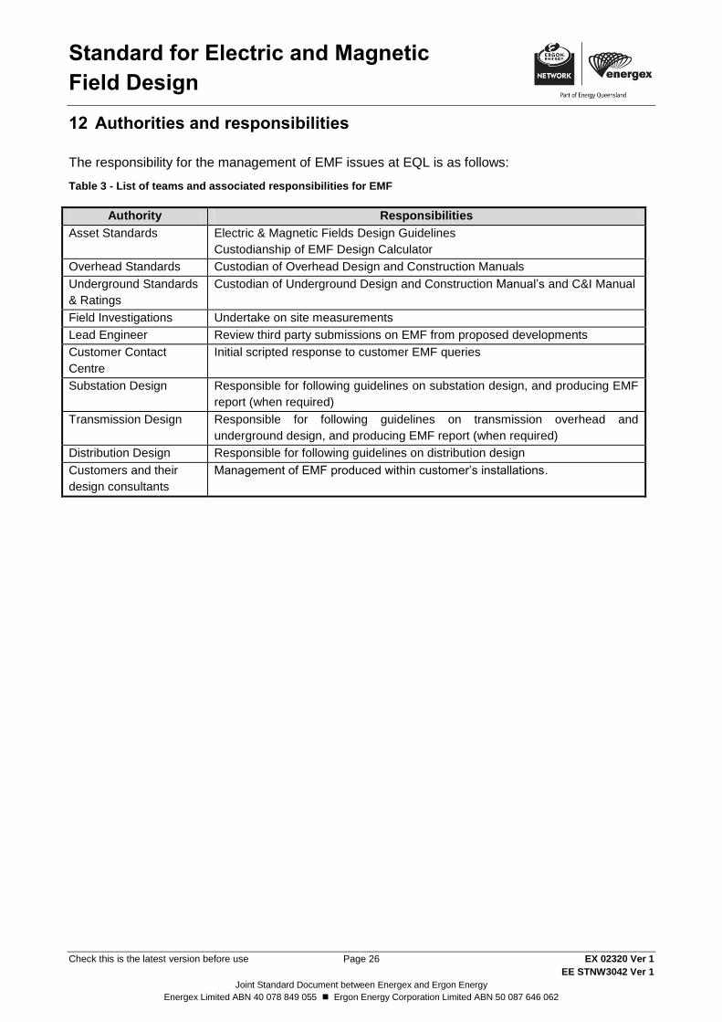
Standard for Electric and Magnetic
Field Design
Check this is the latest version before use Page 26 EX 02320 Ver 1
EE STNW3042 Ver 1
Joint Standard Document between Energex and Ergon Energy
Energex Limited ABN 40 078 849 055 Ergon Energy Corporation Limited ABN 50 087 646 062
12 Authorities and responsibilities
The responsibility for the management of EMF issues at EQL is as follows:
Table 3 - List of teams and associated responsibilities for EMF
Authority Responsibilities
Asset Standards Electric & Magnetic Fields Design Guidelines
Custodianship of EMF Design Calculator
Overhead Standards Custodian of Overhead Design and Construction Manuals
Underground Standards
& Ratings
Custodian of Underground Design and Construction Manual’s and C&I Manual
Field Investigations Undertake on site measurements
Lead Engineer Review third party submissions on EMF from proposed developments
Customer Contact
Centre
Initial scripted response to customer EMF queries
Substation Design Responsible for following guidelines on substation design, and producing EMF
report (when required)
Transmission Design Responsible for following guidelines on transmission overhead and
underground design, and producing EMF report (when required)
Distribution Design Responsible for following guidelines on distribution design
Customers and their
design consultants
Management of EMF produced within customer’s installations.
Standard for Electric and Magnetic
Field Design
Check this is the latest version before use Page 27 EX 02320 Ver 1
EE STNW3042 Ver 1
Joint Standard Document between Energex and Ergon Energy
Energex Limited ABN 40 078 849 055 Ergon Energy Corporation Limited ABN 50 087 646 062
Typical Magnetic Field Profiles (informative) Annex A
Assumptions behind calculations A.1
The magnetic field strengths for overhead (OH) lines have been modelled using an inhouse Excel
program, the standard designs for each construction being obtained from the ENERGEX Overhead
Construction Manual. This manual has been used to determine the relative position of conductors
(conductor configuration) in relation to a reference point at ground level (i.e. centre of the pole) for
each construction. Each standard OH construction (apart from LV) has been modelled as a
balanced 100 A per phase system at various conductor configuration heights.
The program has been used to determine the magnetic field strength normal to the conductors (i.e.
90 ), at 1 m intervals up to 20 m either side of the centre of the pole, at a height 1 m above the
ground. A profile for each construction can then be generated from the magnetic field strength
results.
The relative position of conductors will not vary for each type of construction, but the height of the
conductor configuration above ground will vary according to the size of the pole and the distances
between poles. As the magnetic field strength is directly proportional to the current, each standard
construction i.e. (conductor configuration) is modelled and graphed at 100 A. However field
strength is not linearly proportional to the height of the conductor configuration for each
construction. Thus the field strengths have been modelled at various conductor configuration
heights above the ground at 100 A.
Typically the LV network is not a balanced three phase system, due to the single phase services
being supplied along the length of the overhead mains. The single phase services are generally
evenly distributed over the three phases along the length of the LV network to minimise the
unbalance at any given point. However between single phase services connection points on the
LV mains there will always be some unbalance due to the even number of single phase services
connected at this point (i.e. 4 single phase services). The loads at any given time may also vary
introducing unbalance in the LV OH mains.
For the purposes of this study, all LV overhead standard constructions have been modelled as
having 10% current unbalance on B and C phases.
Where dual circuits are shown the worst case is taken with currents in the same direction.
Magnetic fields for HV underground cables are assumed to have cable screens bonded at one end
only. Bonding at both ends or cross bonding will result in even lower values due to circulating
currents in screen setting up magnetic fields that oppose those from the phase conductor.
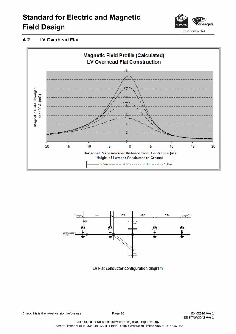
Standard for Electric and Magnetic
Field Design
Check this is the latest version before use Page 28 EX 02320 Ver 1
EE STNW3042 Ver 1
Joint Standard Document between Energex and Ergon Energy
Energex Limited ABN 40 078 849 055 Ergon Energy Corporation Limited ABN 50 087 646 062
LV Overhead Flat A.2

Standard for Electric and Magnetic
Field Design
Check this is the latest version before use Page 29 EX 02320 Ver 1
EE STNW3042 Ver 1
Joint Standard Document between Energex and Ergon Energy
Energex Limited ABN 40 078 849 055 Ergon Energy Corporation Limited ABN 50 087 646 062
LV ABC A.3
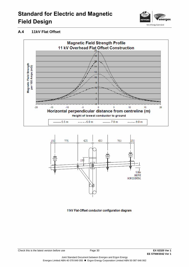
Standard for Electric and Magnetic
Field Design
Check this is the latest version before use Page 30 EX 02320 Ver 1
EE STNW3042 Ver 1
Joint Standard Document between Energex and Ergon Energy
Energex Limited ABN 40 078 849 055 Ergon Energy Corporation Limited ABN 50 087 646 062
11kV Flat Offset A.4

Standard for Electric and Magnetic
Field Design
Check this is the latest version before use Page 31 EX 02320 Ver 1
EE STNW3042 Ver 1
Joint Standard Document between Energex and Ergon Energy
Energex Limited ABN 40 078 849 055 Ergon Energy Corporation Limited ABN 50 087 646 062
33kV Flat Offset A.5
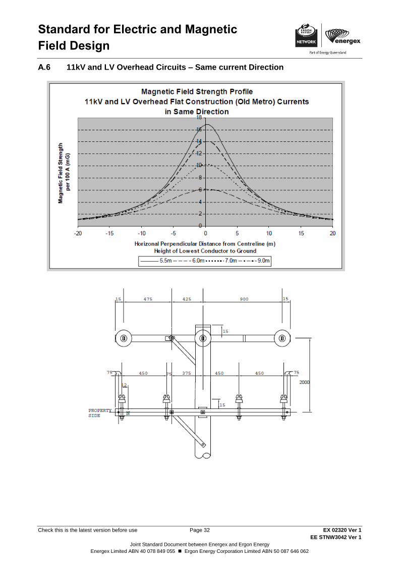
Standard for Electric and Magnetic
Field Design
Check this is the latest version before use Page 32 EX 02320 Ver 1
EE STNW3042 Ver 1
Joint Standard Document between Energex and Ergon Energy
Energex Limited ABN 40 078 849 055 Ergon Energy Corporation Limited ABN 50 087 646 062
11kV and LV Overhead Circuits – Same current Direction A.6
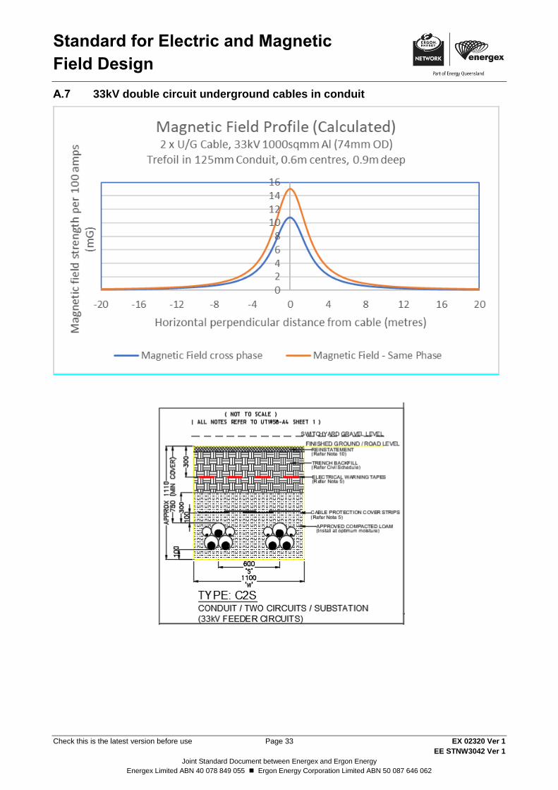
Standard for Electric and Magnetic
Field Design
Check this is the latest version before use Page 33 EX 02320 Ver 1
EE STNW3042 Ver 1
Joint Standard Document between Energex and Ergon Energy
Energex Limited ABN 40 078 849 055 Ergon Energy Corporation Limited ABN 50 087 646 062
33kV double circuit underground cables in conduit A.7
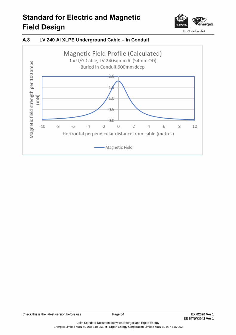
Standard for Electric and Magnetic
Field Design
Check this is the latest version before use Page 34 EX 02320 Ver 1
EE STNW3042 Ver 1
Joint Standard Document between Energex and Ergon Energy
Energex Limited ABN 40 078 849 055 Ergon Energy Corporation Limited ABN 50 087 646 062
LV 240 Al XLPE Underground Cable – In Conduit A.8


![Experiment 2 6. Magnetic Field Induced by Electric Fieldphyslab.snu.ac.kr/documents/manual/En/2-6.pdf · Experiment 2-6. Magnetic Field Induced by Electric Field ... Magnetic Field]](https://img.pdfslide.us/doc/110x75/5ea11c78b8c7202f935229c4/experiment-2-6-magnetic-field-induced-by-electric-experiment-2-6-magnetic-field.jpg)