Embed Size (px)
Citation preview
www.MLEC.com
Main Line Energy Consultants LLC T: 215.855.7477 1240 S Broad St, Suite 100 Lansdale PA 19446
ELECTRIC AND MAGNETIC FIELD (EMF) STUDY
CASSADAGA WIND FARM 115kV Transmission Line 34.5kV Collection System
MLEC Project #: AHV-15-002
AHV PO: 19018-002 AHV Project #: 19018
Prepared For: Applied High Voltage, LLC 403 New Karner Road Albany, NY 12205
Rev. Date Description Prepared By Checked By Approved By3 4/6/16 ISSUE TO CLIENT AC EP CS
Main Line Energy Consultants, LLC 1240 S Broad St, Suite 100
Lansdale PA 19446
Phone: (215) 855-7477
www.MLEC.com
Client Applied High Voltage Project No. AHV-15-002
Project Title Cassadaga Wind Farm EMF
Calculation Title Electric and Magnetic Field Study
AHV PO: 19018-002 Page 2 of 77
TABLE OF CONTENTS
1. Introduction .............................................................................................................................................. 3
2. General Description of Electric and Magnetic Fields ................................................................................. 3
3. Project Description .................................................................................................................................... 7
4. Calculations .............................................................................................................................................. 9
5. Conclusion .............................................................................................................................................. 24
Appendix A – Calculation Output Data ............................................................................................................. 25
Main Line Energy Consultants, LLC 1240 S Broad St, Suite 100
Lansdale PA 19446
Phone: (215) 855-7477
www.MLEC.com
Client Applied High Voltage Project No. AHV-15-002
Project Title Cassadaga Wind Farm EMF
Calculation Title Electric and Magnetic Field Study
AHV PO: 19018-002 Page 3 of 77
1. INTRODUCTION
The proposed Cassadaga Wind Farm is located approximately 4.5 miles south-east of Cassadaga, NY. The proposed configuration contains approximately 5.5 miles of overhead 115kV transmission line, and numerous connecting taps for the 34.5kV collection system, totaling approximately 20 miles. An evaluation was performed of the power-frequency (60-Hertz) electric and magnetic fields associated with the proposed Cassadaga Wind Farm 115 kV Transmission Line, and 34.5kV collection system. The purpose of this study was to perform computer modeling of the lines associated with the project and prepare a technical report of the calculation results, which are presented herein. The study took a cross-section at typical locations which contain unique EMF characteristics, and then provided results for those sections which can be used as representative examples for the lines with similar framing or layout.
2. GENERAL DESCRIPTION OF ELECTRIC AND MAGNETIC FIELDS
A. BACKGROUND INFORMATION
The generation, delivery and use of electricity produce electric and magnetic fields. Electric and magnetic fields are created by electrical voltage and electrical current respectively. Electrical facilities, such as power lines associated with the Cassadaga Wind Farm 115 kV Transmission Line Project, produce electric and magnetic fields during operation. The exposure to electric and magnetic fields is complex and comes from multiple sources in the home and workplace in addition to power lines.
B. UNITS OF MEASURE
Electric field values are reported using units of Volts per meter (V/m). Often the electric field is reported using thousands of Volts per meter (or kV/m). Magnetic field values are reported using units of gauss (G). However, it is usually more convenient to report magnetic field using milliGauss (mG) which is equal to one-thousandth of a gauss (i.e., 1 mG = 0.001 G). Some technical reports also use the unit Tesla (T) or microTesla (µT; 1 µT = 0.000001 T) for magnetic fields. The conversion between these two units is 1 mG = 0.1 µT and 1 µT = 10mG.
Main Line Energy Consultants, LLC 1240 S Broad St, Suite 100
Lansdale PA 19446
Phone: (215) 855-7477
www.MLEC.com
Client Applied High Voltage Project No. AHV-15-002
Project Title Cassadaga Wind Farm EMF
Calculation Title Electric and Magnetic Field Study
AHV PO: 19018-002 Page 4 of 77
C. ELECTRIC FIELDS
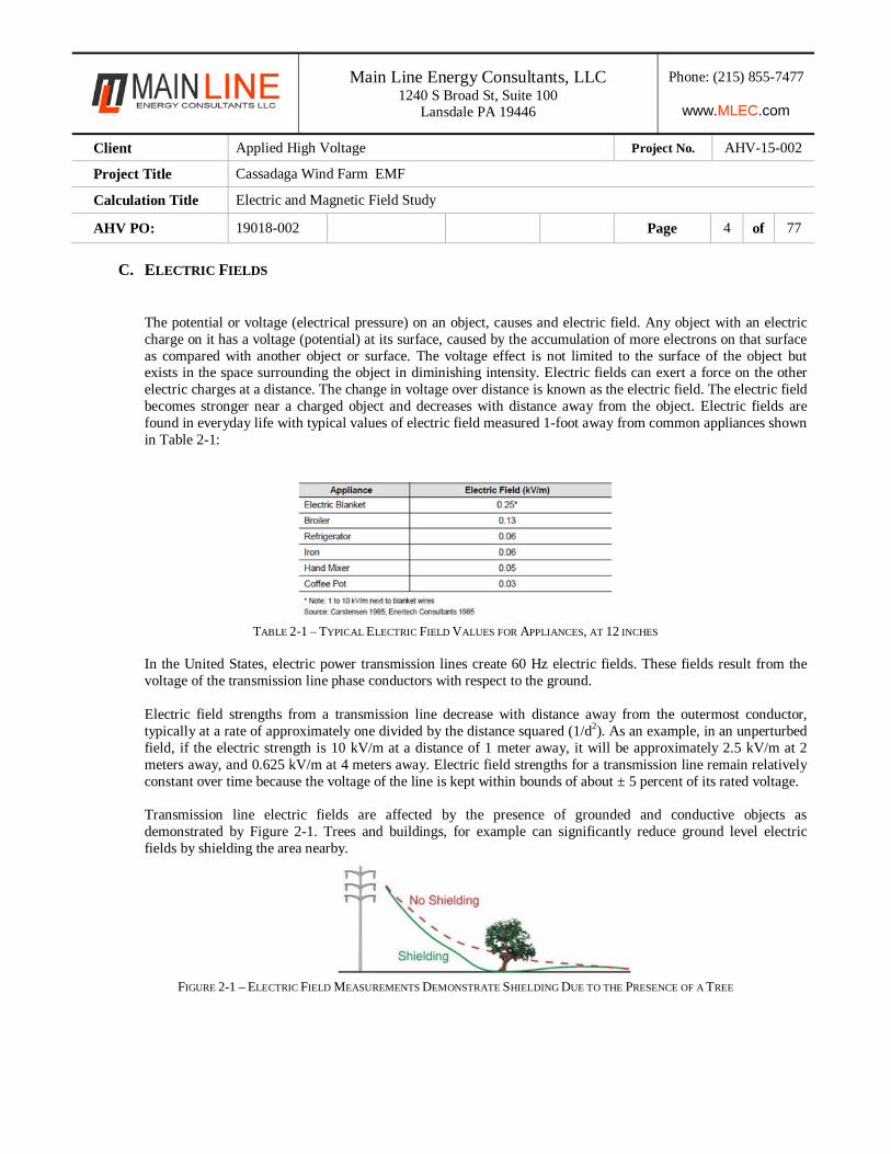
The potential or voltage (electrical pressure) on an object, causes and electric field. Any object with an electric charge on it has a voltage (potential) at its surface, caused by the accumulation of more electrons on that surface as compared with another object or surface. The voltage effect is not limited to the surface of the object but exists in the space surrounding the object in diminishing intensity. Electric fields can exert a force on the other electric charges at a distance. The change in voltage over distance is known as the electric field. The electric field becomes stronger near a charged object and decreases with distance away from the object. Electric fields are found in everyday life with typical values of electric field measured 1-foot away from common appliances shown in Table 2-1:
TABLE 2-1 – TYPICAL ELECTRIC FIELD VALUES FOR APPLIANCES, AT 12 INCHES
In the United States, electric power transmission lines create 60 Hz electric fields. These fields result from the voltage of the transmission line phase conductors with respect to the ground. Electric field strengths from a transmission line decrease with distance away from the outermost conductor, typically at a rate of approximately one divided by the distance squared (1/d2). As an example, in an unperturbed field, if the electric strength is 10 kV/m at a distance of 1 meter away, it will be approximately 2.5 kV/m at 2 meters away, and 0.625 kV/m at 4 meters away. Electric field strengths for a transmission line remain relatively constant over time because the voltage of the line is kept within bounds of about ± 5 percent of its rated voltage. Transmission line electric fields are affected by the presence of grounded and conductive objects as demonstrated by Figure 2-1. Trees and buildings, for example can significantly reduce ground level electric fields by shielding the area nearby.
FIGURE 2-1 – ELECTRIC FIELD MEASUREMENTS DEMONSTRATE SHIELDING DUE TO THE PRESENCE OF A TREE
Main Line Energy Consultants, LLC 1240 S Broad St, Suite 100
Lansdale PA 19446
Phone: (215) 855-7477
www.MLEC.com
Client Applied High Voltage Project No. AHV-15-002
Project Title Cassadaga Wind Farm EMF
Calculation Title Electric and Magnetic Field Study
AHV PO: 19018-002 Page 5 of 77
D. MAGNETIC FIELDS
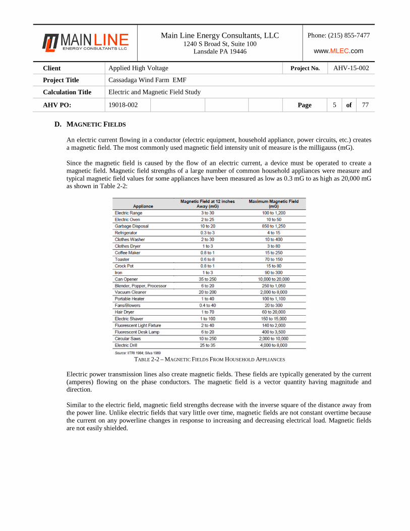
An electric current flowing in a conductor (electric equipment, household appliance, power circuits, etc.) creates a magnetic field. The most commonly used magnetic field intensity unit of measure is the milligauss (mG). Since the magnetic field is caused by the flow of an electric current, a device must be operated to create a magnetic field. Magnetic field strengths of a large number of common household appliances were measure and typical magnetic field values for some appliances have been measured as low as 0.3 mG to as high as 20,000 mG as shown in Table 2-2:
TABLE 2-2 – MAGNETIC FIELDS FROM HOUSEHOLD APPLIANCES
Electric power transmission lines also create magnetic fields. These fields are typically generated by the current (amperes) flowing on the phase conductors. The magnetic field is a vector quantity having magnitude and direction. Similar to the electric field, magnetic field strengths decrease with the inverse square of the distance away from the power line. Unlike electric fields that vary little over time, magnetic fields are not constant overtime because the current on any powerline changes in response to increasing and decreasing electrical load. Magnetic fields are not easily shielded.
Main Line Energy Consultants, LLC 1240 S Broad St, Suite 100
Lansdale PA 19446
Phone: (215) 855-7477
www.MLEC.com
Client Applied High Voltage Project No. AHV-15-002
Project Title Cassadaga Wind Farm EMF
Calculation Title Electric and Magnetic Field Study
AHV PO: 19018-002 Page 6 of 77
E. EMF STANDARD DESIGN LIMITS
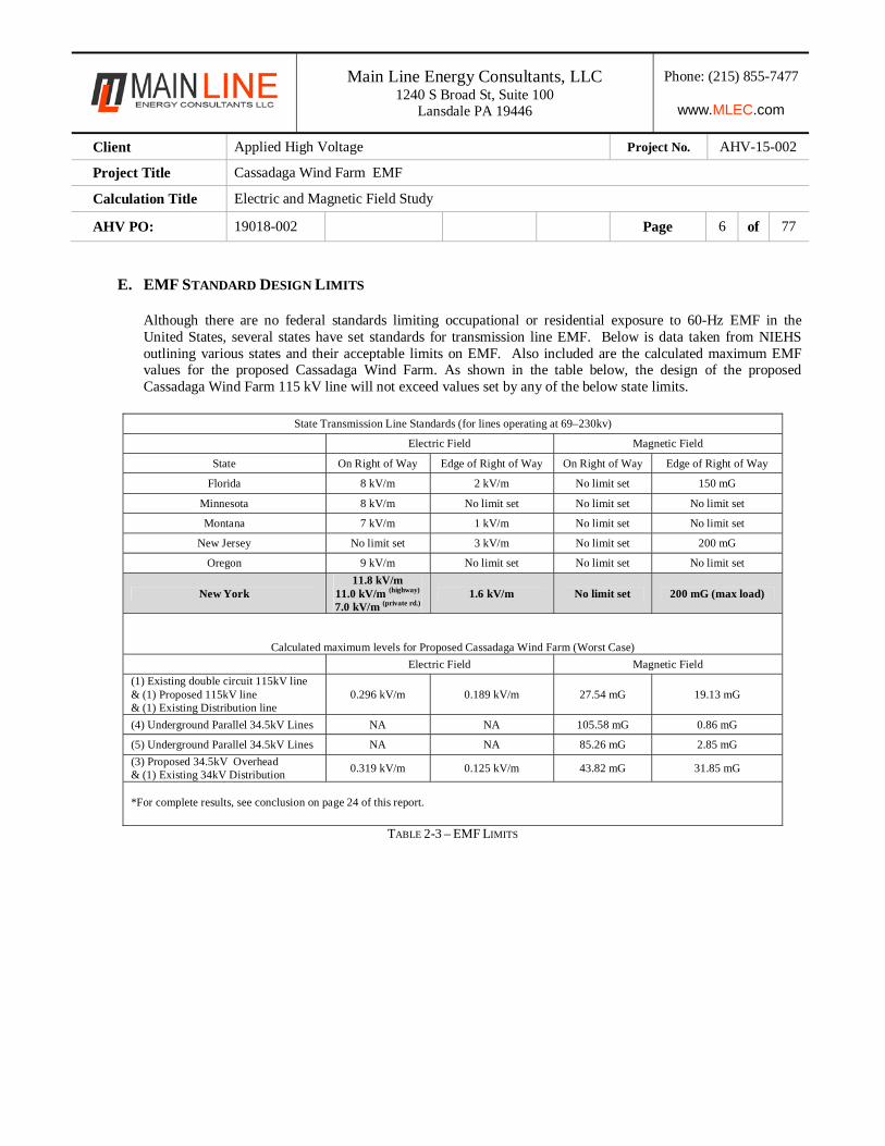
Although there are no federal standards limiting occupational or residential exposure to 60-Hz EMF in the United States, several states have set standards for transmission line EMF. Below is data taken from NIEHS outlining various states and their acceptable limits on EMF. Also included are the calculated maximum EMF values for the proposed Cassadaga Wind Farm. As shown in the table below, the design of the proposed Cassadaga Wind Farm 115 kV line will not exceed values set by any of the below state limits.
State Transmission Line Standards (for lines operating at 69–230kv)
Electric Field Magnetic Field
State On Right of Way Edge of Right of Way On Right of Way Edge of Right of Way
Florida 8 kV/m 2 kV/m No limit set 150 mG
Minnesota 8 kV/m No limit set No limit set No limit set
Montana 7 kV/m 1 kV/m No limit set No limit set
New Jersey No limit set 3 kV/m No limit set 200 mG
Oregon 9 kV/m No limit set No limit set No limit set
New York 11.8 kV/m
11.0 kV/m (highway) 7.0 kV/m (private rd.)
1.6 kV/m No limit set 200 mG (max load)
Calculated maximum levels for Proposed Cassadaga Wind Farm (Worst Case)
Electric Field Magnetic Field
(1) Existing double circuit 115kV line & (1) Proposed 115kV line & (1) Existing Distribution line
0.296 kV/m 0.189 kV/m 27.54 mG 19.13 mG
(4) Underground Parallel 34.5kV Lines NA NA 105.58 mG 0.86 mG
(5) Underground Parallel 34.5kV Lines NA NA 85.26 mG 2.85 mG
(3) Proposed 34.5kV Overhead & (1) Existing 34kV Distribution
0.319 kV/m 0.125 kV/m 43.82 mG 31.85 mG
*For complete results, see conclusion on page 24 of this report.
TABLE 2-3 – EMF LIMITS
Main Line Energy Consultants, LLC 1240 S Broad St, Suite 100
Lansdale PA 19446
Phone: (215) 855-7477
www.MLEC.com
Client Applied High Voltage Project No. AHV-15-002
Project Title Cassadaga Wind Farm EMF
Calculation Title Electric and Magnetic Field Study
AHV PO: 19018-002 Page 7 of 77
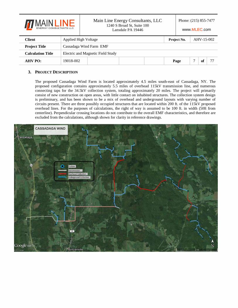
3. PROJECT DESCRIPTION The proposed Cassadaga Wind Farm is located approximately 4.5 miles south-east of Cassadaga, NY. The proposed configuration contains approximately 5.5 miles of overhead 115kV transmission line, and numerous connecting taps for the 34.5kV collection system, totaling approximately 20 miles. The project will primarily consist of new construction on open areas, with little contact on inhabited structures. The collection system design is preliminary, and has been shown to be a mix of overhead and underground layouts with varying number of circuits present. There are three possibly occupied structures that are located within 200 ft. of the 115kV proposed overhead lines. For the purposes of calculations, the right of way is assumed to be 100 ft. in width (50ft from centerline). Perpendicular crossing locations do not contribute to the overall EMF characteristics, and therefore are excluded from the calculations, although shown for clarity in reference drawings.
Main Line Energy Consultants, LLC 1240 S Broad St, Suite 100
Lansdale PA 19446
Phone: (215) 855-7477
www.MLEC.com
Client Applied High Voltage Project No. AHV-15-002
Project Title Cassadaga Wind Farm EMF
Calculation Title Electric and Magnetic Field Study
AHV PO: 19018-002 Page 8 of 77
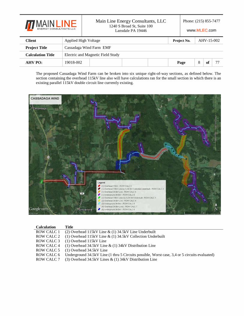
The proposed Cassadaga Wind Farm can be broken into six unique right-of-way sections, as defined below. The section containing the overhead 115kV line also will have calculations ran for the small section in which there is an existing parallel 115kV double circuit line currently existing.
Calculation Title ROW CALC 1 (2) Overhead 115kV Line & (1) 34.5kV Line UnderbuiltROW CALC 2 (1) Overhead 115kV Line & (1) 34.5kV Collection UnderbuiltROW CALC 3 (1) Overhead 115kV LineROW CALC 4 (1) Overhead 34.5kV Line & (1) 34kV Distribution LineROW CALC 5 (1) Overhead 34.5kV LineROW CALC 6 Underground 34.5kV Line (1 thru 5 Circuits possible, Worst case, 3,4 or 5 circuits evaluated)ROW CALC 7 (3) Overhead 34.5kV Lines & (1) 34kV Distribution Line
Main Line Energy Consultants, LLC 1240 S Broad St, Suite 100
Lansdale PA 19446
Phone: (215) 855-7477
www.MLEC.com
Client Applied High Voltage Project No. AHV-15-002
Project Title Cassadaga Wind Farm EMF
Calculation Title Electric and Magnetic Field Study
AHV PO: 19018-002 Page 9 of 77
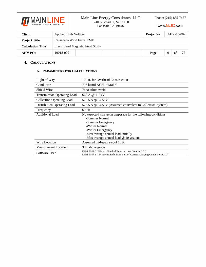
4. CALCULATIONS
A. PARAMETERS FOR CALCULATIONS
Right of Way 100 ft. for Overhead Construction
Conductor 795 kcmil ACSR “Drake”
Shield Wire 7no8 Alumoweld
Transmission Operating Load 665 A @ 115kV
Collection Operating Load 528.5 A @ 34.5kV
Distribution Operating Load 528.5 A @ 34.5kV (Assumed equivalent to Collection System)
Frequency 60 Hz Additional Load No expected change in amperage for the following conditions:
-Summer Normal -Summer Emergency -Winter Normal -Winter Emergency -Max average annual load initially -Max average annual load @ 10 yrs. out
Wire Location Assumed mid-span sag of 10 ft.
Measurement Location 3 ft. above grade
Software Used EPRI EMF-2 “Electric Field of Transmission Lines in 2-D” EPRI EMF-6 “ Magnetic Field from Sets of Current Carrying Conductors (2-D)”
Main Line Energy Consultants, LLC 1240 S Broad St, Suite 100
Lansdale PA 19446
Phone: (215) 855-7477
www.MLEC.com
Client Applied High Voltage Project No. AHV-15-002
Project Title Cassadaga Wind Farm EMF
Calculation Title Electric and Magnetic Field Study
AHV PO: 19018-002 Page 10 of 77
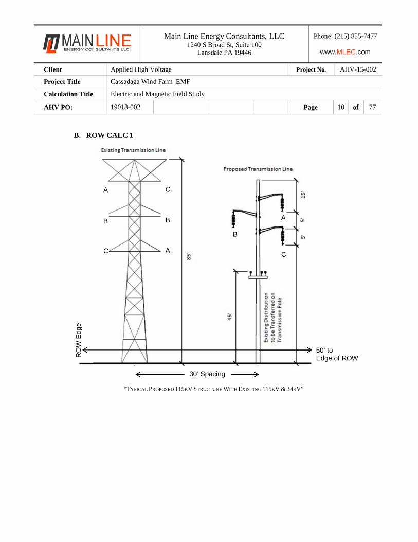
B. ROW CALC 1
“TYPICAL PROPOSED 115KV STRUCTURE WITH EXISTING 115KV & 34KV”
C
B
A
A
B
CA
B
C
30’ Spacing
RO
W E
dge
50’ to Edge of ROW
Main Line Energy Consultants, LLC 1240 S Broad St, Suite 100
Lansdale PA 19446
Phone: (215) 855-7477
www.MLEC.com
Client Applied High Voltage Project No. AHV-15-002
Project Title Cassadaga Wind Farm EMF
Calculation Title Electric and Magnetic Field Study
AHV PO: 19018-002 Page 11 of 77
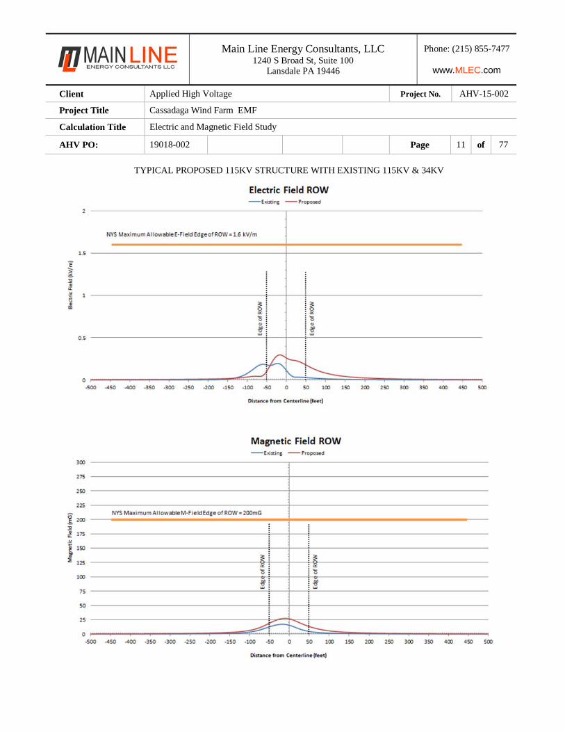
TYPICAL PROPOSED 115KV STRUCTURE WITH EXISTING 115KV & 34KV
Main Line Energy Consultants, LLC 1240 S Broad St, Suite 100
Lansdale PA 19446
Phone: (215) 855-7477
www.MLEC.com
Client Applied High Voltage Project No. AHV-15-002
Project Title Cassadaga Wind Farm EMF
Calculation Title Electric and Magnetic Field Study
AHV PO: 19018-002 Page 12 of 77
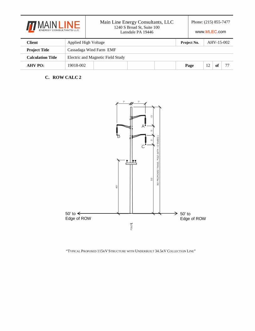
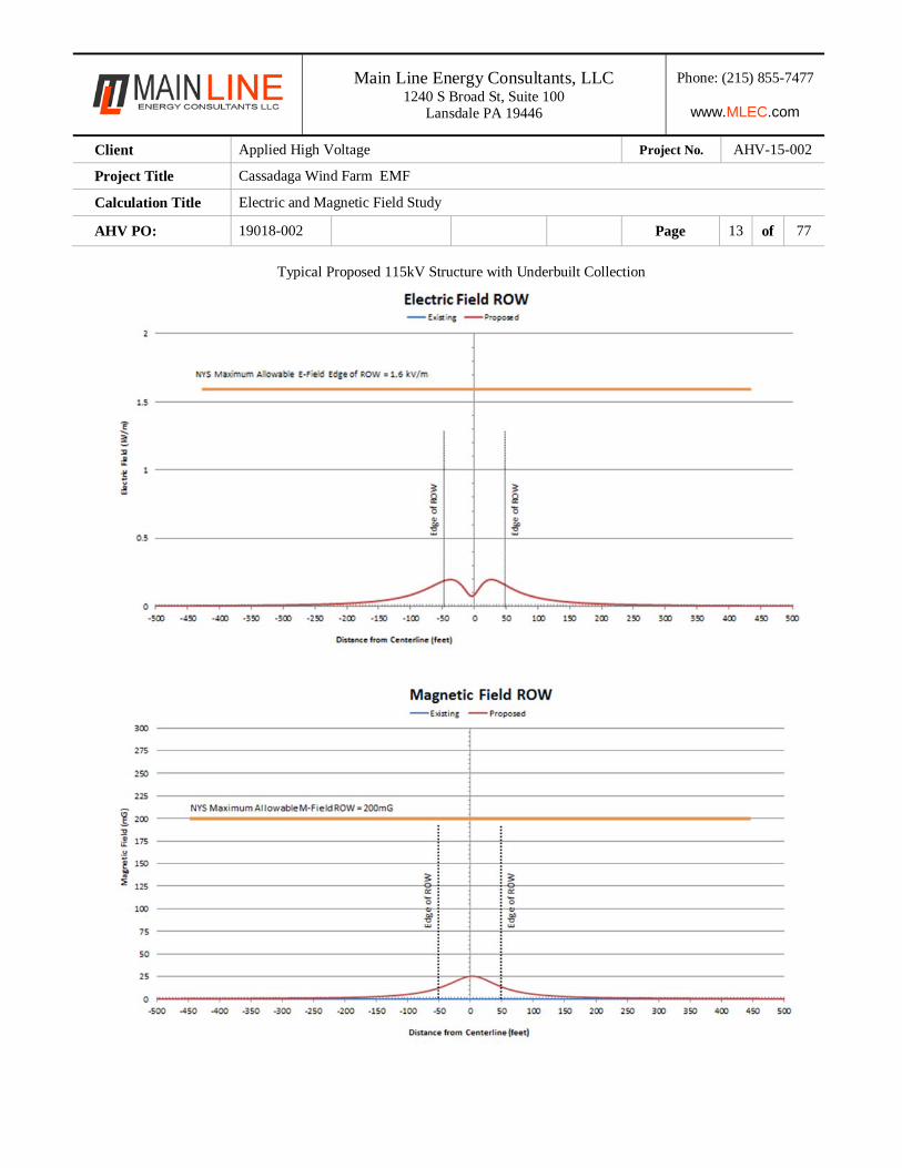
C. ROW CALC 2
“TYPICAL PROPOSED 115KV STRUCTURE WITH UNDERBUILT 34.5KV COLLECTION LINE”
50’ to Edge of ROW
50’ to Edge of ROW
Main Line Energy Consultants, LLC 1240 S Broad St, Suite 100
Lansdale PA 19446
Phone: (215) 855-7477
www.MLEC.com
Client Applied High Voltage Project No. AHV-15-002
Project Title Cassadaga Wind Farm EMF
Calculation Title Electric and Magnetic Field Study
AHV PO: 19018-002 Page 13 of 77
Typical Proposed 115kV Structure with Underbuilt Collection
Main Line Energy Consultants, LLC 1240 S Broad St, Suite 100
Lansdale PA 19446
Phone: (215) 855-7477
www.MLEC.com
Client Applied High Voltage Project No. AHV-15-002
Project Title Cassadaga Wind Farm EMF
Calculation Title Electric and Magnetic Field Study
AHV PO: 19018-002 Page 14 of 77
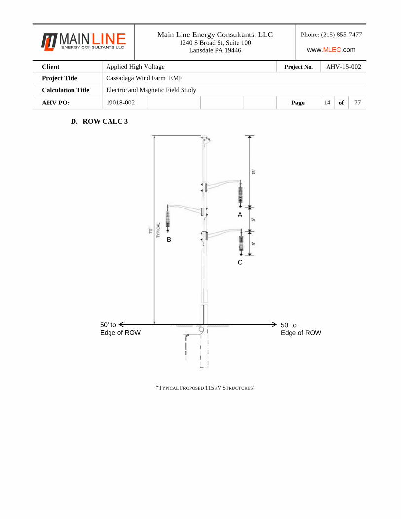
D. ROW CALC 3
“TYPICAL PROPOSED 115KV STRUCTURES”
A
B
C
50’ to Edge of ROW
50’ to Edge of ROW
Main Line Energy Consultants, LLC 1240 S Broad St, Suite 100
Lansdale PA 19446
Phone: (215) 855-7477
www.MLEC.com
Client Applied High Voltage Project No. AHV-15-002
Project Title Cassadaga Wind Farm EMF
Calculation Title Electric and Magnetic Field Study
AHV PO: 19018-002 Page 15 of 77
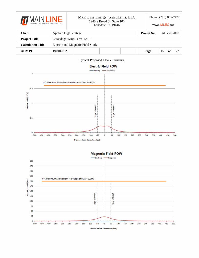
Typical Proposed 115kV Structure
Main Line Energy Consultants, LLC 1240 S Broad St, Suite 100
Lansdale PA 19446
Phone: (215) 855-7477
www.MLEC.com
Client Applied High Voltage Project No. AHV-15-002
Project Title Cassadaga Wind Farm EMF
Calculation Title Electric and Magnetic Field Study
AHV PO: 19018-002 Page 16 of 77
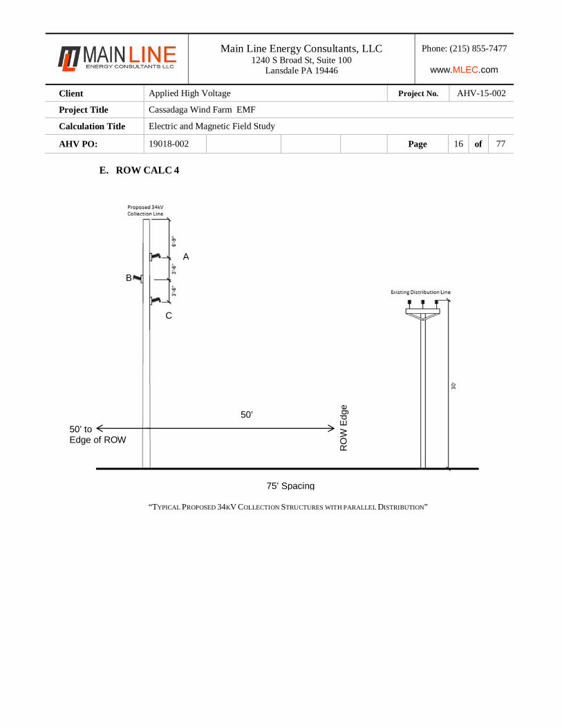
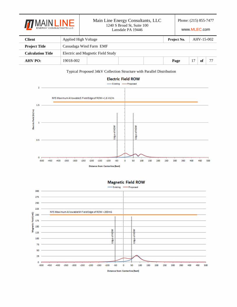
E. ROW CALC 4
“TYPICAL PROPOSED 34KV COLLECTION STRUCTURES WITH PARALLEL DISTRIBUTION”
75’ Spacing
A
B
C
50’
RO
W E
dge
50’ to Edge of ROW
Main Line Energy Consultants, LLC 1240 S Broad St, Suite 100
Lansdale PA 19446
Phone: (215) 855-7477
www.MLEC.com
Client Applied High Voltage Project No. AHV-15-002
Project Title Cassadaga Wind Farm EMF
Calculation Title Electric and Magnetic Field Study
AHV PO: 19018-002 Page 17 of 77
Typical Proposed 34kV Collection Structure with Parallel Distribution
Main Line Energy Consultants, LLC 1240 S Broad St, Suite 100
Lansdale PA 19446
Phone: (215) 855-7477
www.MLEC.com
Client Applied High Voltage Project No. AHV-15-002
Project Title Cassadaga Wind Farm EMF
Calculation Title Electric and Magnetic Field Study
AHV PO: 19018-002 Page 18 of 77
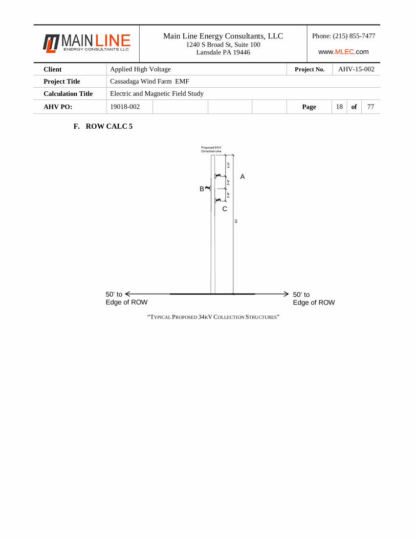
F. ROW CALC 5
“TYPICAL PROPOSED 34KV COLLECTION STRUCTURES”
A
B
C
50’ to Edge of ROW
50’ to Edge of ROW
Main Line Energy Consultants, LLC 1240 S Broad St, Suite 100
Lansdale PA 19446
Phone: (215) 855-7477
www.MLEC.com
Client Applied High Voltage Project No. AHV-15-002
Project Title Cassadaga Wind Farm EMF
Calculation Title Electric and Magnetic Field Study
AHV PO: 19018-002 Page 19 of 77
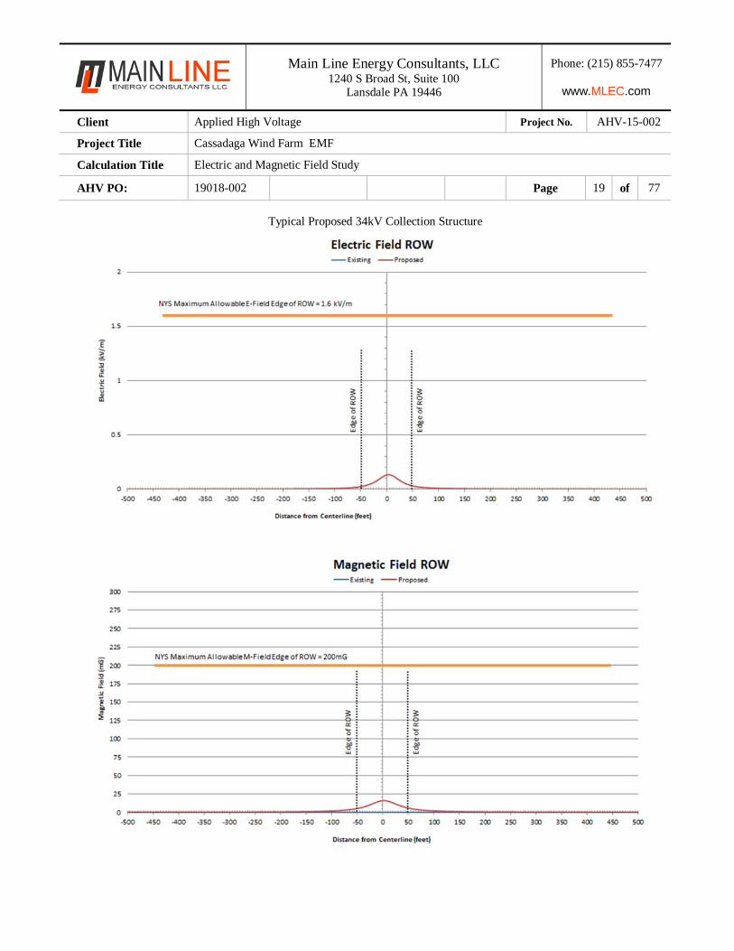
Typical Proposed 34kV Collection Structure
Main Line Energy Consultants, LLC 1240 S Broad St, Suite 100
Lansdale PA 19446
Phone: (215) 855-7477
www.MLEC.com
Client Applied High Voltage Project No. AHV-15-002
Project Title Cassadaga Wind Farm EMF
Calculation Title Electric and Magnetic Field Study
AHV PO: 19018-002 Page 20 of 77
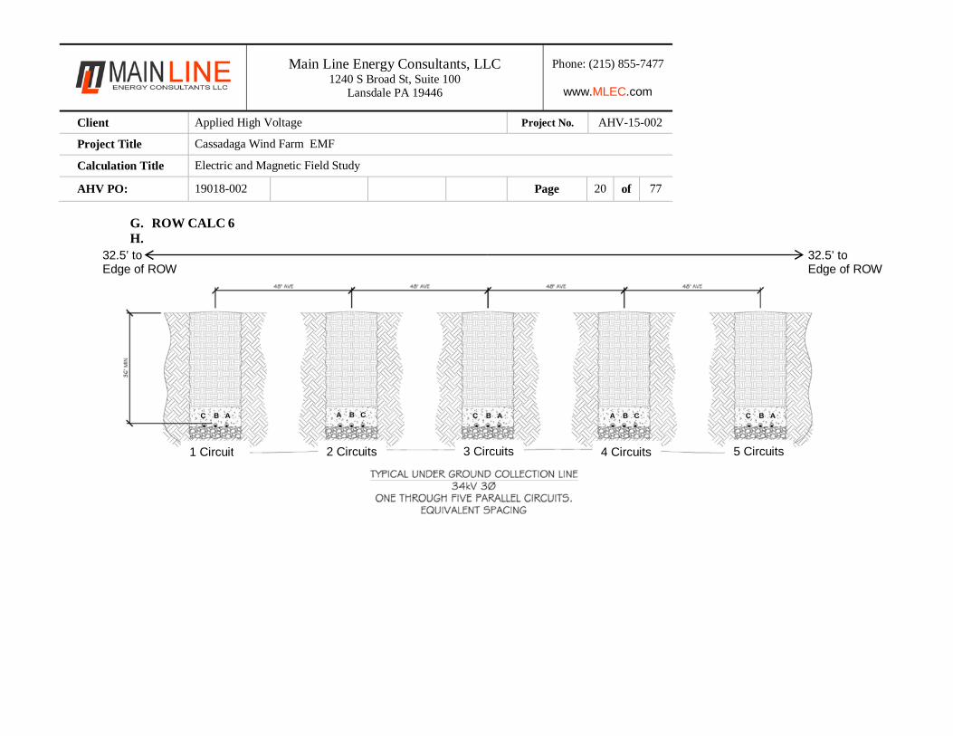
G. ROW CALC 6 H.
4 Circuits 5 Circuits
C B A C B A C B A A B C A B C
3 Circuits1 Circuit 2 Circuits
32.5’ to Edge of ROW
32.5’ to Edge of ROW
Main Line Energy Consultants, LLC 1240 S Broad St, Suite 100
Lansdale PA 19446
Phone: (215) 855-7477
www.MLEC.com
Client Applied High Voltage Project No. AHV-15-002
Project Title Cassadaga Wind Farm EMF
Calculation Title Electric and Magnetic Field Study
AHV PO: 19018-002 Page 21 of 77
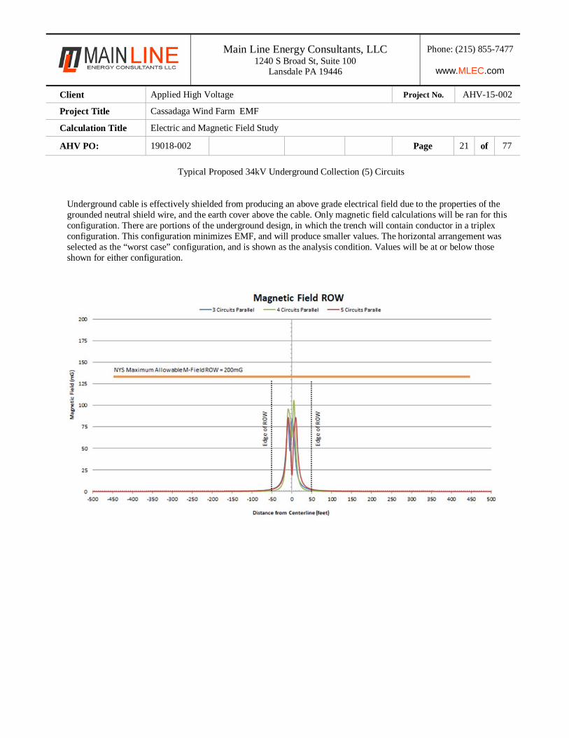
Typical Proposed 34kV Underground Collection (5) Circuits
Underground cable is effectively shielded from producing an above grade electrical field due to the properties of the grounded neutral shield wire, and the earth cover above the cable. Only magnetic field calculations will be ran for this configuration. There are portions of the underground design, in which the trench will contain conductor in a triplex configuration. This configuration minimizes EMF, and will produce smaller values. The horizontal arrangement was selected as the “worst case” configuration, and is shown as the analysis condition. Values will be at or below those shown for either configuration.
Main Line Energy Consultants, LLC 1240 S Broad St, Suite 100
Lansdale PA 19446
Phone: (215) 855-7477
www.MLEC.com
Client Applied High Voltage Project No. AHV-15-002
Project Title Cassadaga Wind Farm EMF
Calculation Title Electric and Magnetic Field Study
AHV PO: 19018-002 Page 22 of 77
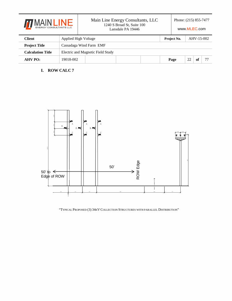
I. ROW CALC 7
“TYPICAL PROPOSED (3) 34KV COLLECTION STRUCTURES WITH PARALLEL DISTRIBUTION”
50’
RO
W E
dge
50’ to Edge of ROW
Main Line Energy Consultants, LLC 1240 S Broad St, Suite 100
Lansdale PA 19446
Phone: (215) 855-7477
www.MLEC.com
Client Applied High Voltage Project No. AHV-15-002
Project Title Cassadaga Wind Farm EMF
Calculation Title Electric and Magnetic Field Study
AHV PO: 19018-002 Page 23 of 77
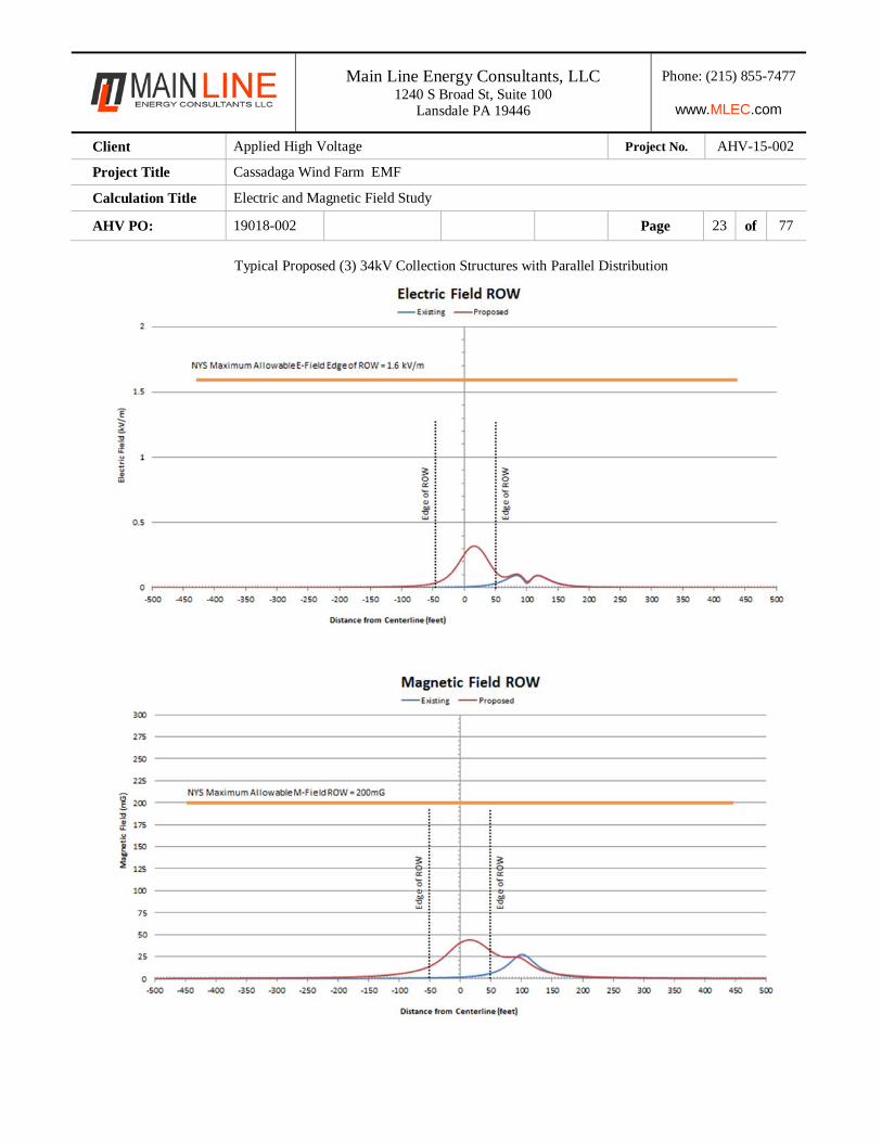
Typical Proposed (3) 34kV Collection Structures with Parallel Distribution
Main Line Energy Consultants, LLC 1240 S Broad St, Suite 100
Lansdale PA 19446
Phone: (215) 855-7477
www.MLEC.com
Client Applied High Voltage Project No. AHV-15-002
Project Title Cassadaga Wind Farm EMF
Calculation Title Electric and Magnetic Field Study
AHV PO: 19018-002 Page 24 of 77
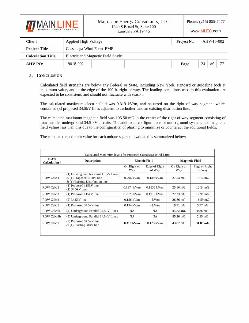
5. CONCLUSION
Calculated field strengths are below any Federal or State, including New York, standard or guideline both at maximum value, and at the edge of the 100 ft. right of way. The loading conditions used in this evaluation are expected to be consistent, and should not fluctuate with season. The calculated maximum electric field was 0.319 kV/m, and occurred on the right of way segment which contained (3) proposed 34.5kV lines adjacent to eachother, and an existing distribution line. The calculated maximum magnetic field was 105.58 mG in the center of the right of way segment consisting of four parallel underground 34.5 kV circuits. The additional configurations of underground systems had magnetic field values less than this due to the configuration of phasing to minimize or counteract the additional fields. The calculated maximum value for each unique segment evaluated is summarized below:
Calculated Maximum levels for Proposed Cassadaga Wind Farm
ROW Calculation #
Description Electric Field Magnetic Field
On Right of
Way Edge of Right
of Way On Right of
Way Edge of Right
of Way
ROW Calc 1 (1) Existing double circuit 115kV Lines& (1) Proposed 115kV line & (1) Existing Distribution line
0.296 kV/m 0.189 kV/m 27.54 mG 19.13 mG
ROW Calc 2 (1) Proposed 115kV line (1) 34.5kV line
0.1974 kV/m 0.1836 kV/m 25.16 mG 13.24 mG
ROW Calc 3 (1) Proposed 115kV line 0.2325 kV/m 0.1919 kV/m 22.23 mG 12.91 mG
ROW Calc 4 (2) 34.5kV line 0.126 kV/m - kV/m 26.86 mG 16.59 mG
ROW Calc 5 (1) Proposed 34.5kV line 0.134 kV/m - kV/m 19.91 mG 5.77 mG
ROW Calc 6a (4) Underground Parallel 34.5kV Lines NA NA 105.58 mG 0.86 mG
ROW Calc 6b (5) Underground Parallel 34.5kV Lines NA NA 85.26 mG 2.85 mG
ROW Calc 7 (3) Proposed 34.5kV line & (1) Existing 34kV line 0.319 kV/m 0.125 kV/m 43.82 mG 31.85 mG