Embed Size (px)
Citation preview
STM32 MICROCONTROLLER:
DIGITAL-TO-ANALOG
CONVERTER (DAC)
Prof. Yasser Mostafa Kadah Lecture 6
DAC Introduction
DAC module is a 12-bit, voltage output digital-to-analog
converter
DAC can be configured in 8- or 12-bit mode and may be used
in conjunction with the DMA controller
In 12-bit mode, the data could be left- or right-aligned
DAC has two output channels, each with its own converter
In dual DAC channel mode, conversions could be done independently or
simultaneously when both channels are grouped together for
synchronous update operations
Input reference pin, VREF+ (shared with ADC) is available for
better resolution
DAC Main Features
Two DAC converters: one output channel each
Left or right data alignment in 12-bit mode
Synchronized update capability
Noise-wave generation
Triangular-wave generation
Dual DAC channel for independent or simultaneous conversions
DMA capability for each channel
DMA underrun error detection
External triggers for conversion
Input voltage reference, VREF+
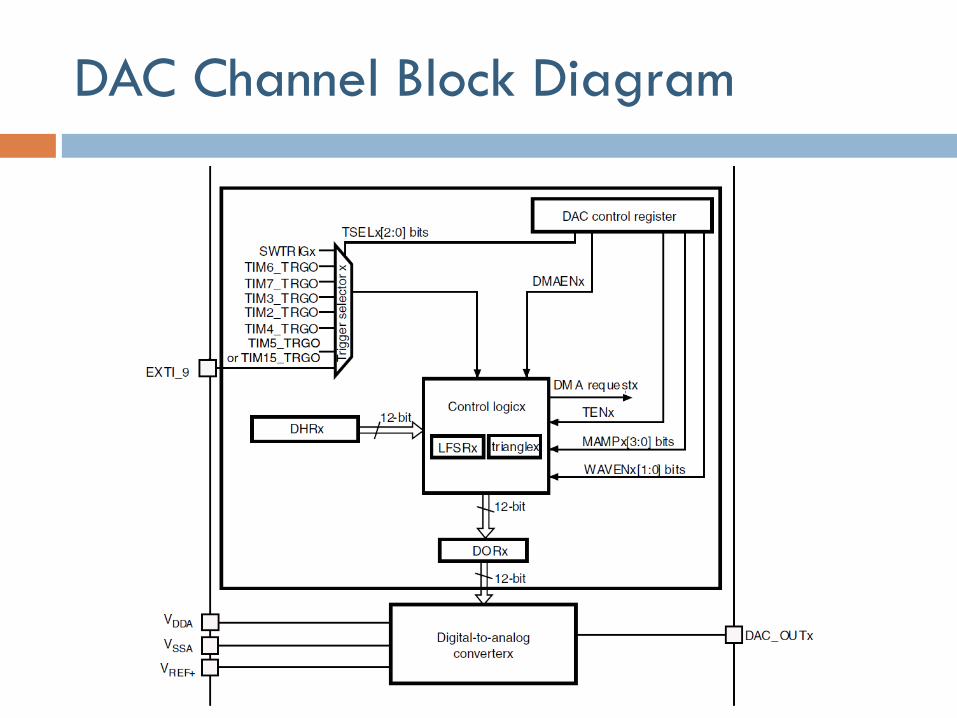
DAC Channel Block Diagram
DAC Pins
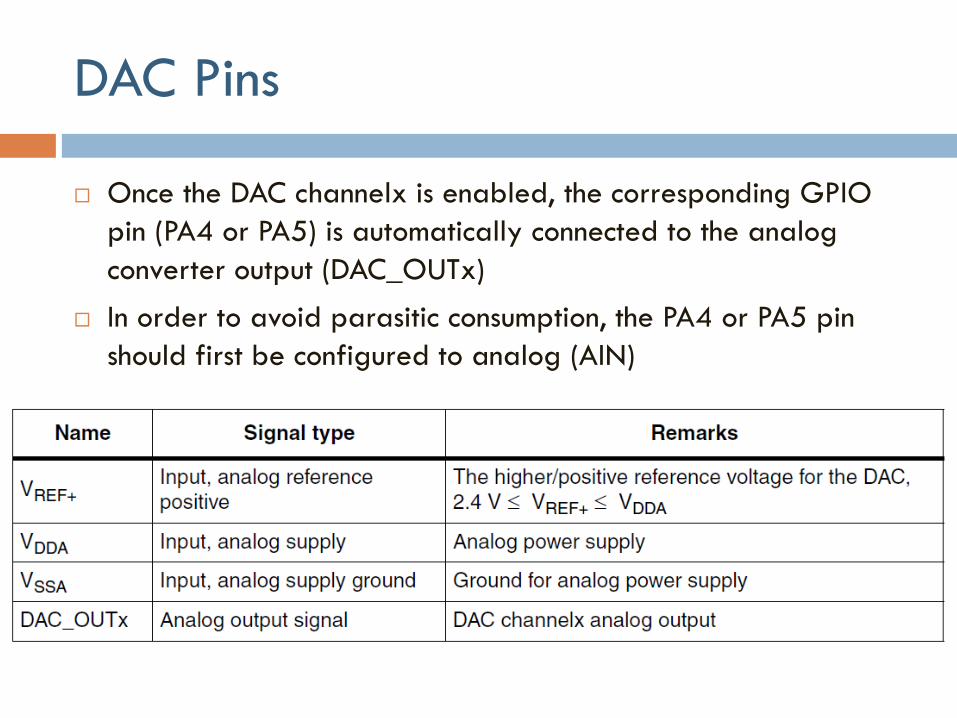
Once the DAC channelx is enabled, the corresponding GPIO
pin (PA4 or PA5) is automatically connected to the analog
converter output (DAC_OUTx)
In order to avoid parasitic consumption, the PA4 or PA5 pin
should first be configured to analog (AIN)
DAC Functional Description
DAC channel enable
Setting its corresponding ENx bit in the DAC_CR register
DAC channel is then enabled after a startup time tWAKEUP
DAC output buffer enable
DAC integrates two output buffers to reduce output impedance, and to
drive external loads directly without having to add an external op amp
Enabled using the corresponding BOFFx bit in the DAC_CR register
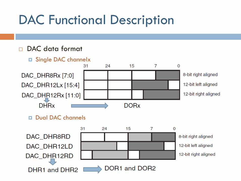
DAC Functional Description
DAC data format
Single DAC channelx
Dual DAC channels
DAC Functional Description
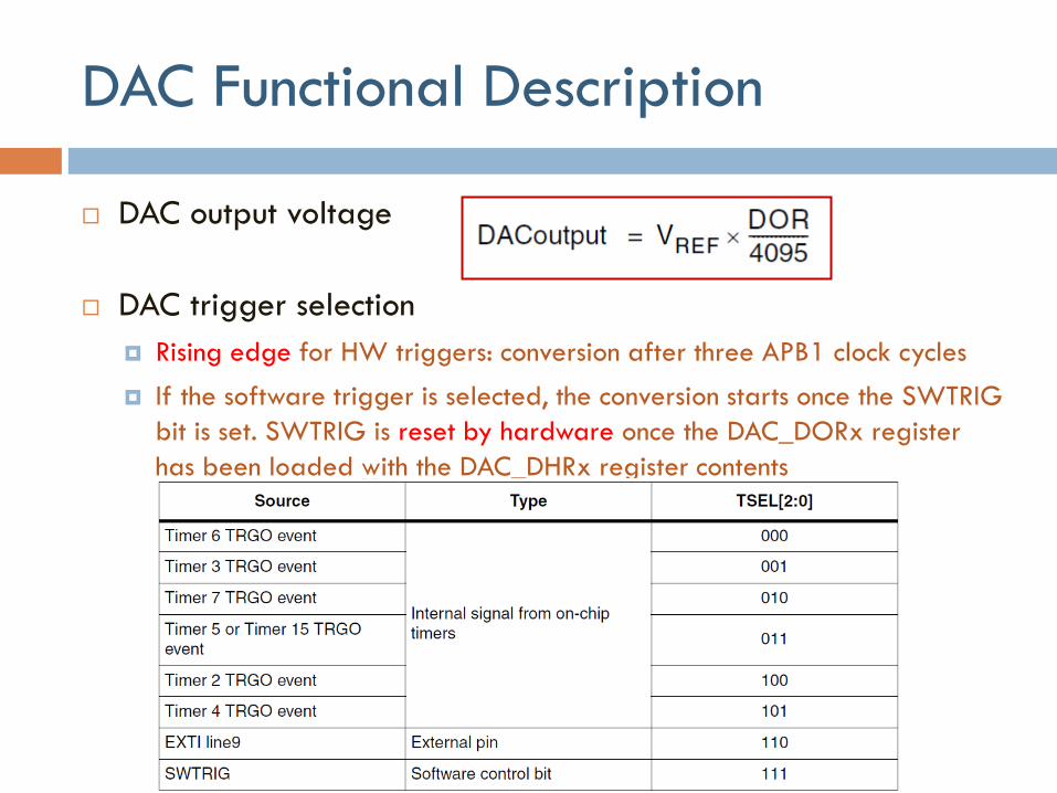
DAC output voltage
DAC trigger selection
Rising edge for HW triggers: conversion after three APB1 clock cycles
If the software trigger is selected, the conversion starts once the SWTRIG
bit is set. SWTRIG is reset by hardware once the DAC_DORx register
has been loaded with the DAC_DHRx register contents
DAC Conversion
DAC_DORx cannot be written directly and any data transfer to the
DAC channelx must be performed by loading the DAC_DHRx
register
Data stored in the DAC_DHRx register are automatically transferred
to the DAC_DORx register after one APB1 clock cycle, if no
hardware trigger is selected (TENx bit in DAC_CR register is reset)
When hardware trigger is selected (TENx bit in DAC_CR register is
set) and a trigger occurs, transfer is performed three APB1 clock
cycles later
When DAC_DORx is loaded with the DAC_DHRx contents, the
analog output voltage becomes available after a time tSETTLING that
depends on power supply voltage and analog output load
DAC Conversion
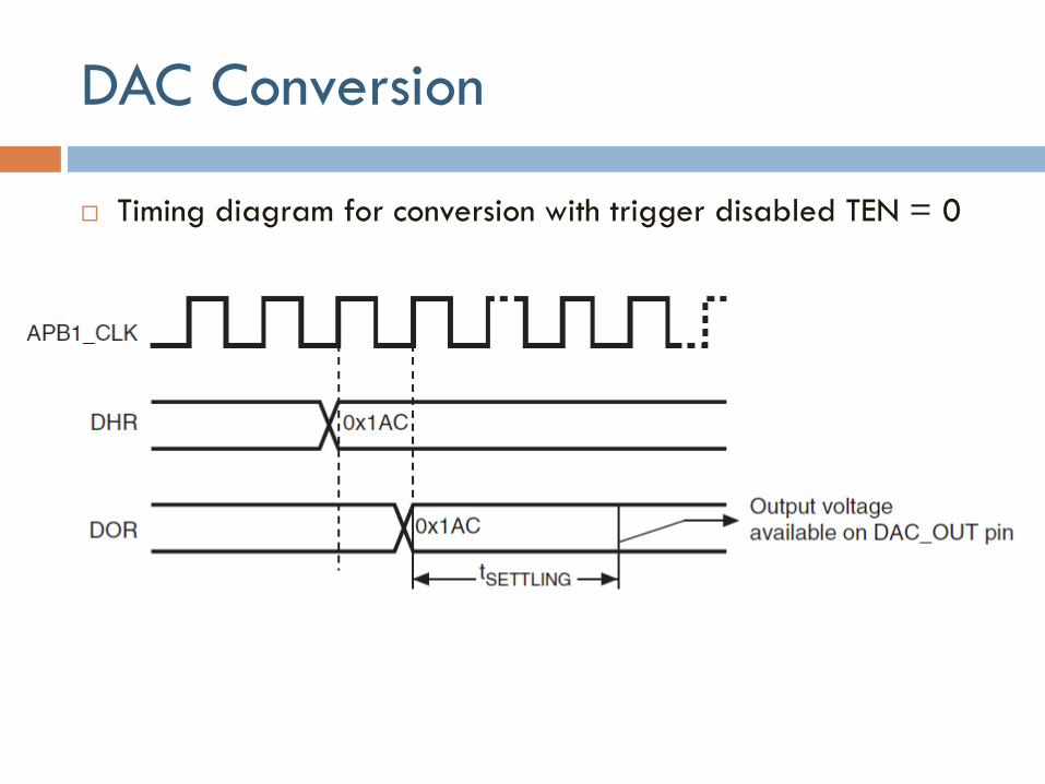
Timing diagram for conversion with trigger disabled TEN = 0
Noise Generation
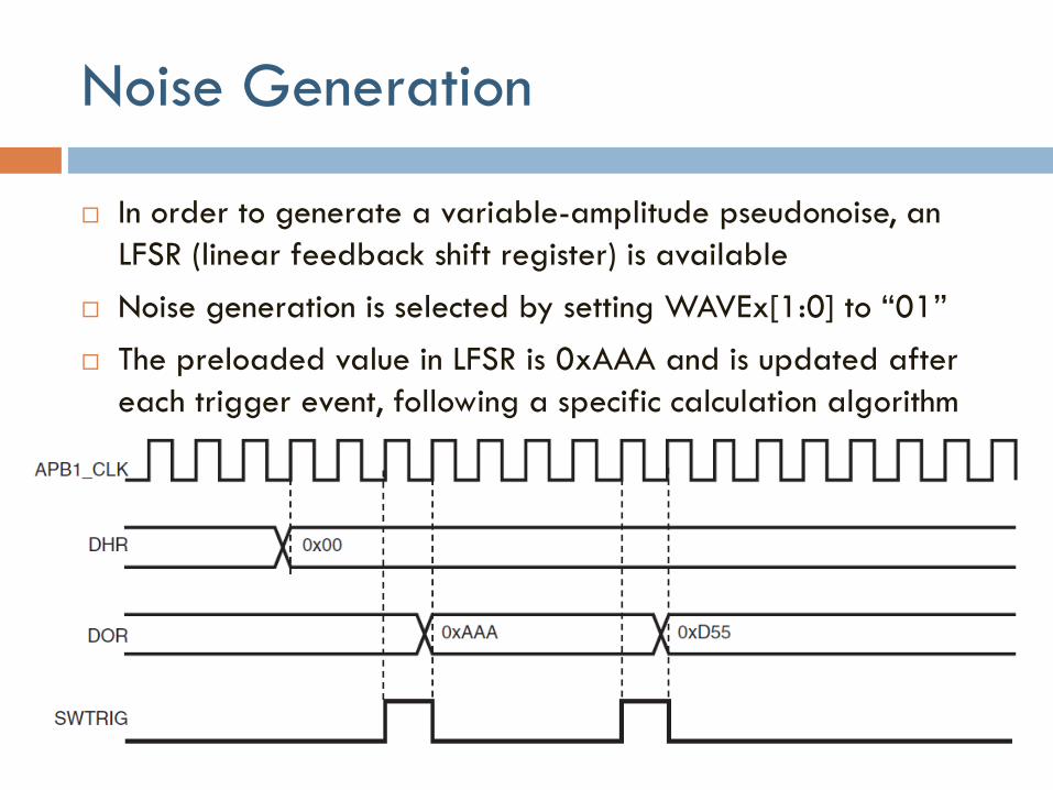
In order to generate a variable-amplitude pseudonoise, an
LFSR (linear feedback shift register) is available
Noise generation is selected by setting WAVEx[1:0] to “01”
The preloaded value in LFSR is 0xAAA and is updated after
each trigger event, following a specific calculation algorithm
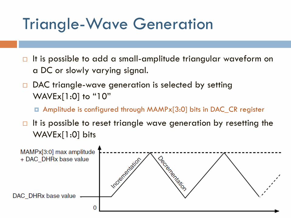
Triangle-Wave Generation
It is possible to add a small-amplitude triangular waveform on
a DC or slowly varying signal.
DAC triangle-wave generation is selected by setting
WAVEx[1:0] to “10”
Amplitude is configured through MAMPx[3:0] bits in DAC_CR register
It is possible to reset triangle wave generation by resetting the
WAVEx[1:0] bits
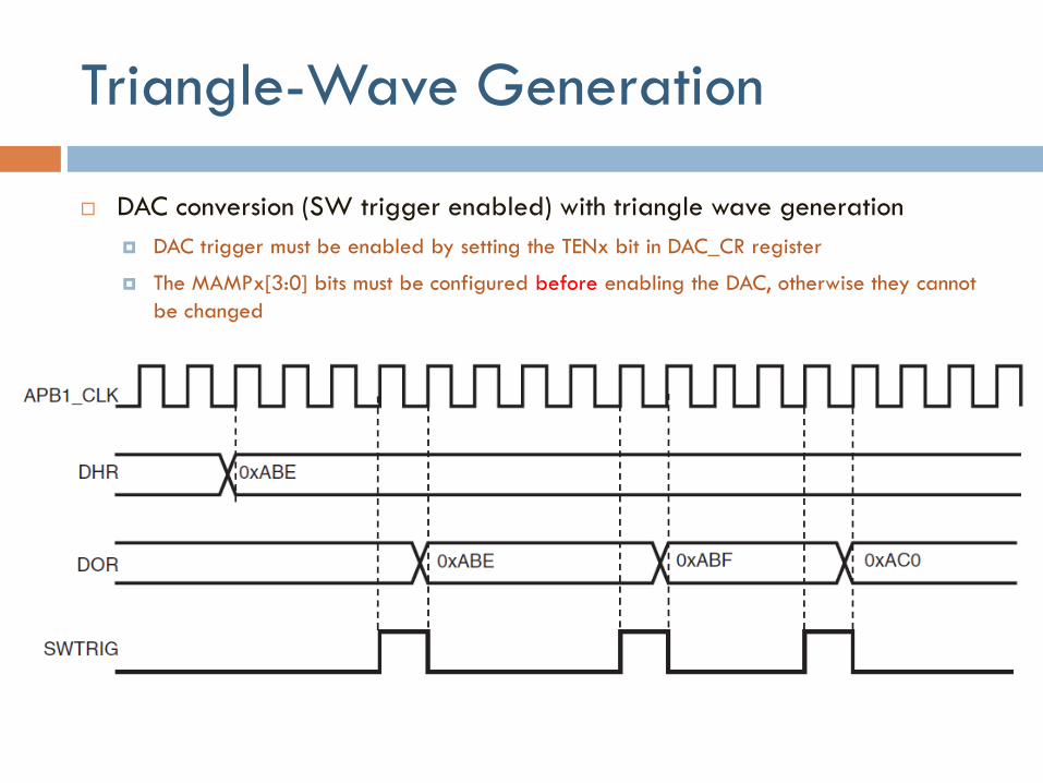
Triangle-Wave Generation
DAC conversion (SW trigger enabled) with triangle wave generation
DAC trigger must be enabled by setting the TENx bit in DAC_CR register
The MAMPx[3:0] bits must be configured before enabling the DAC, otherwise they cannot
be changed
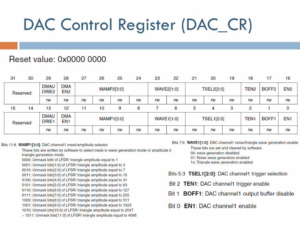
DAC Control Register (DAC_CR)
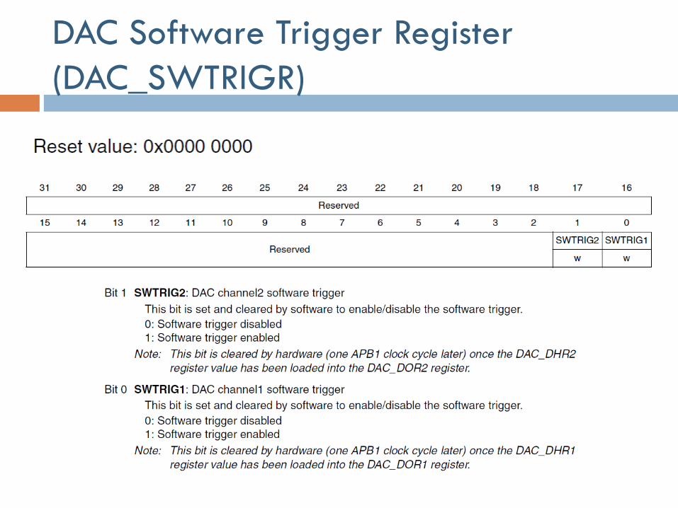
DAC Software Trigger Register
(DAC_SWTRIGR)
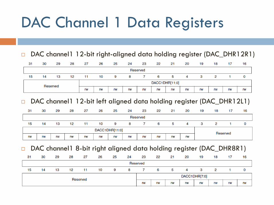
DAC Channel 1 Data Registers
DAC channel1 12-bit right-aligned data holding register (DAC_DHR12R1)
DAC channel1 12-bit left aligned data holding register (DAC_DHR12L1)
DAC channel1 8-bit right aligned data holding register (DAC_DHR8R1)
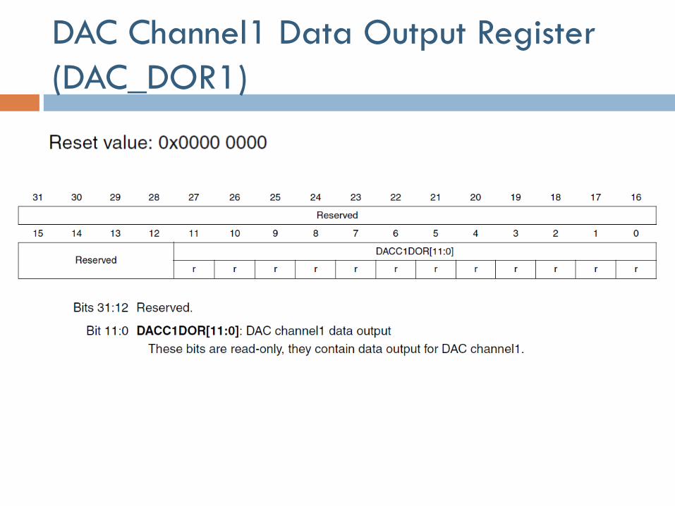
DAC Channel1 Data Output Register
(DAC_DOR1)
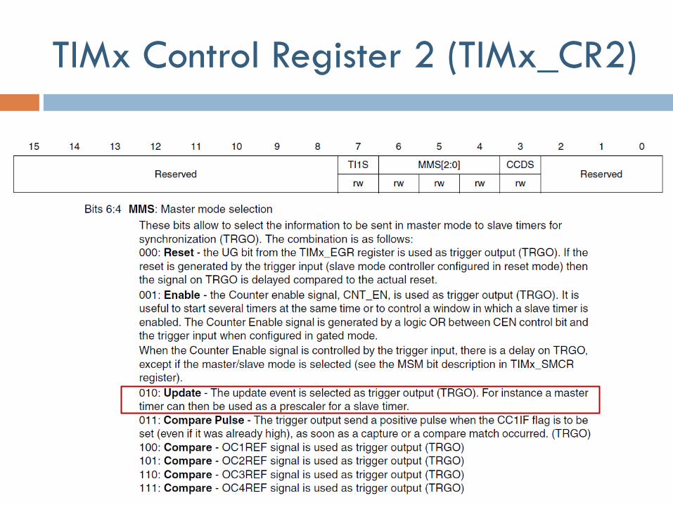
TIMx Control Register 2 (TIMx_CR2)
Assignments
ARM Project #5