Embed Size (px)
Citation preview
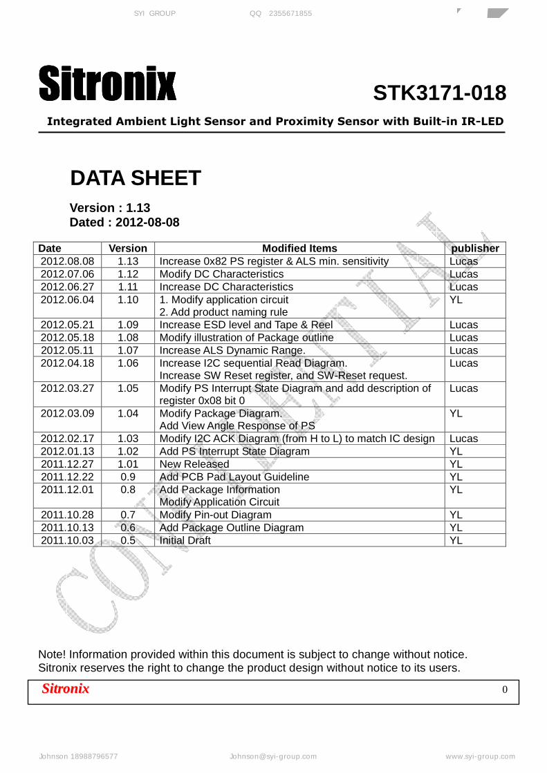
SitronixSitronixSitronixSitronix STK3171-018
Integrated Ambient Light Sensor and Proximity Sensor with Built-in IR-LED
SSiittrroonniixx 0
DATA SHEET Version : 1.13 Dated : 2012-08-08
Date Version Modified Items publisher 2012.08.08 1.13 Increase 0x82 PS register & ALS min. sensitivity Lucas 2012.07.06 1.12 Modify DC Characteristics Lucas 2012.06.27 1.11 Increase DC Characteristics Lucas 2012.06.04 1.10 1. Modify application circuit
2. Add product naming rule YL
2012.05.21 1.09 Increase ESD level and Tape & Reel Lucas 2012.05.18 1.08 Modify illustration of Package outline Lucas 2012.05.11 1.07 Increase ALS Dynamic Range. Lucas 2012.04.18 1.06 Increase I2C sequential Read Diagram.
Increase SW Reset register, and SW-Reset request. Lucas
2012.03.27 1.05 Modify PS Interrupt State Diagram and add description of register 0x08 bit 0
Lucas
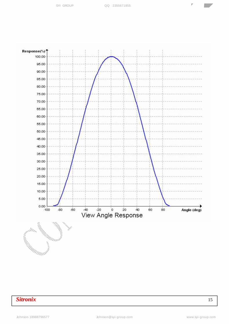
2012.03.09 1.04 Modify Package Diagram. Add View Angle Response of PS
YL
2012.02.17 1.03 Modify I2C ACK Diagram (from H to L) to match IC design Lucas 2012.01.13 1.02 Add PS Interrupt State Diagram YL 2011.12.27 1.01 New Released YL 2011.12.22 0.9 Add PCB Pad Layout Guideline YL 2011.12.01 0.8 Add Package Information
Modify Application Circuit YL
2011.10.28 0.7 Modify Pin-out Diagram YL 2011.10.13 0.6 Add Package Outline Diagram YL 2011.10.03 0.5 Initial Draft YL
Note! Information provided within this document is subject to change without notice. Sitronix reserves the right to change the product design without notice to its users.
芯扬国际(香港)有限公司 SYI GROUP 企业QQ:2355671855 专业传感器供应商
Johnson 18988796577 [email protected] www.syi-group.com
SSiittrroonniixx STK3171-018
SSiittrroonniixx 1
1. OVERVIEW
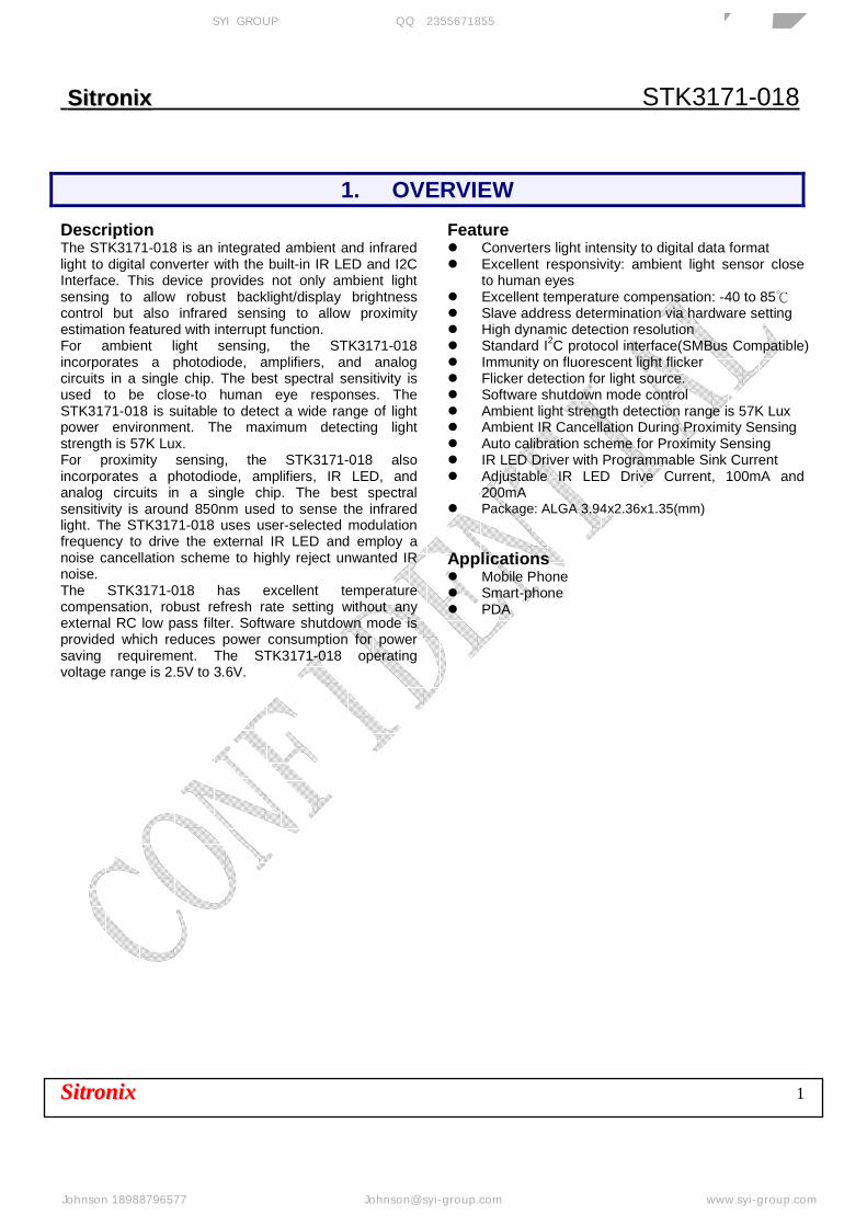
Description The STK3171-018 is an integrated ambient and infrared light to digital converter with the built-in IR LED and I2C Interface. This device provides not only ambient light sensing to allow robust backlight/display brightness control but also infrared sensing to allow proximity estimation featured with interrupt function. For ambient light sensing, the STK3171-018 incorporates a photodiode, amplifiers, and analog circuits in a single chip. The best spectral sensitivity is used to be close-to human eye responses. The STK3171-018 is suitable to detect a wide range of light power environment. The maximum detecting light strength is 57K Lux. For proximity sensing, the STK3171-018 also incorporates a photodiode, amplifiers, IR LED, and analog circuits in a single chip. The best spectral sensitivity is around 850nm used to sense the infrared light. The STK3171-018 uses user-selected modulation frequency to drive the external IR LED and employ a noise cancellation scheme to highly reject unwanted IR noise. The STK3171-018 has excellent temperature compensation, robust refresh rate setting without any external RC low pass filter. Software shutdown mode is provided which reduces power consumption for power saving requirement. The STK3171-018 operating voltage range is 2.5V to 3.6V.
Feature Converters light intensity to digital data format Excellent responsivity: ambient light sensor close
to human eyes Excellent temperature compensation: -40 to 85 Slave address determination via hardware setting High dynamic detection resolution Standard I2C protocol interface(SMBus Compatible) Immunity on fluorescent light flicker Flicker detection for light source. Software shutdown mode control Ambient light strength detection range is 57K Lux Ambient IR Cancellation During Proximity Sensing Auto calibration scheme for Proximity Sensing IR LED Driver with Programmable Sink Current Adjustable IR LED Drive Current, 100mA and
200mA Package: ALGA 3.94x2.36x1.35(mm) Applications Mobile Phone Smart-phone PDA
芯扬国际(香港)有限公司 SYI GROUP 企业QQ:2355671855 专业传感器供应商
Johnson 18988796577 [email protected] www.syi-group.com
SSiittrroonniixx 2
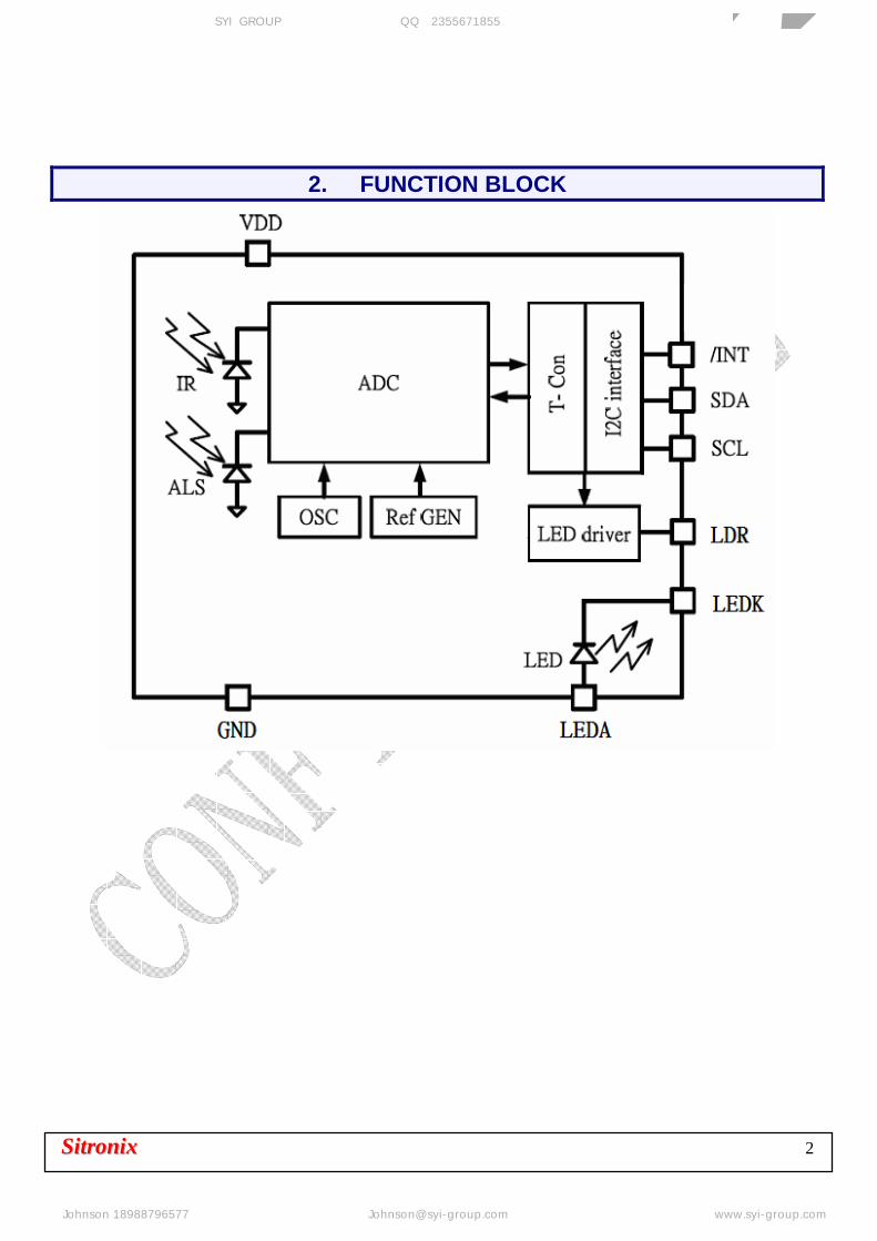
2. FUNCTION BLOCK
芯扬国际(香港)有限公司 SYI GROUP 企业QQ:2355671855 专业传感器供应商
Johnson 18988796577 [email protected] www.syi-group.com
SSiittrroonniixx 3
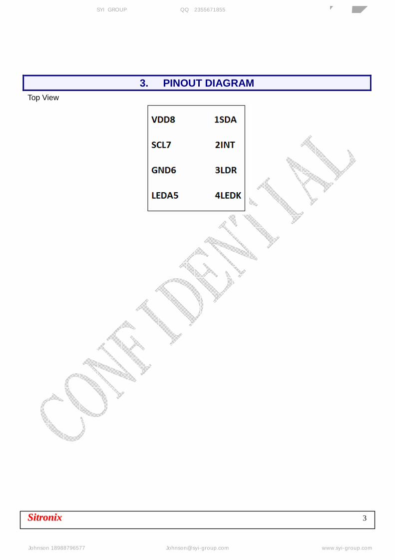
3. PINOUT DIAGRAM Top View
芯扬国际(香港)有限公司 SYI GROUP 企业QQ:2355671855 专业传感器供应商
Johnson 18988796577 [email protected] www.syi-group.com
SSiittrroonniixx 4
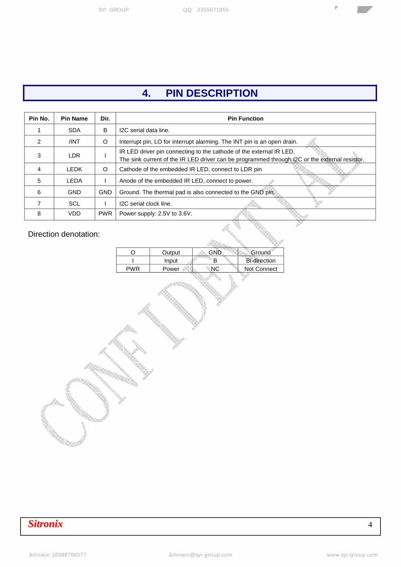
4. PIN DESCRIPTION Pin No. Pin Name Dir. Pin Function
1 SDA B I2C serial data line.
2 /INT O Interrupt pin, LO for interrupt alarming. The INT pin is an open drain.
3 LDR I IR LED driver pin connecting to the cathode of the external IR LED. The sink current of the IR LED driver can be programmed through I2C or the external resistor.
4 LEDK O Cathode of the embedded IR LED, connect to LDR pin
5 LEDA I Anode of the embedded IR LED, connect to power.
6 GND GND Ground. The thermal pad is also connected to the GND pin.
7 SCL I I2C serial clock line.
8 VDD PWR Power supply: 2.5V to 3.6V.
Direction denotation:
O Output GND Ground I Input B Bi-direction
PWR Power NC Not Connect
芯扬国际(香港)有限公司 SYI GROUP 企业QQ:2355671855 专业传感器供应商
Johnson 18988796577 [email protected] www.syi-group.com

SSiittrroonniixx 5
5. ELECTRICAL SPECIFICATIONS Absolute Maximum Ratings
Symbol Parameter Min. Typ. Max. Unit
VDD Supply voltage -0.3 — 3.6 V
Ta Operation temperature -40 — 85 °C
Ts Storage temperature -40 — 85 °C
NOTE: All voltages are measured with respect to GND Recommended Operating Conditions
Symbol Parameter Min. Typ. Max. Unit
VDD Supply voltage 2.5 2.8 3.6 V fI2C Clock frequency of I2C — — 400 KHz
Ta Operation temperature -40 — 85 °C
NOTE: All voltages are measured with respect to GND
Symbol Parameter Max. Unit
4 (HBM) kV 200 (MM) V
ESD Electrostatic discharge protection
100 (Latch Up) mA
NOTE: All voltages are measured with respect to GND
55..11 DDCC CChhaarraacctteerriissttiiccss
Electrical and Optical specifications
Symbol Parameter Condition Min. Typ. Max. Unit
VDD Supply Voltage 2.5 3.6 V VI2C I2C Supply Voltage 1.7 3.6 V ICC Supply current VDD=2.8V, 01h=09h=0x00 90 µA
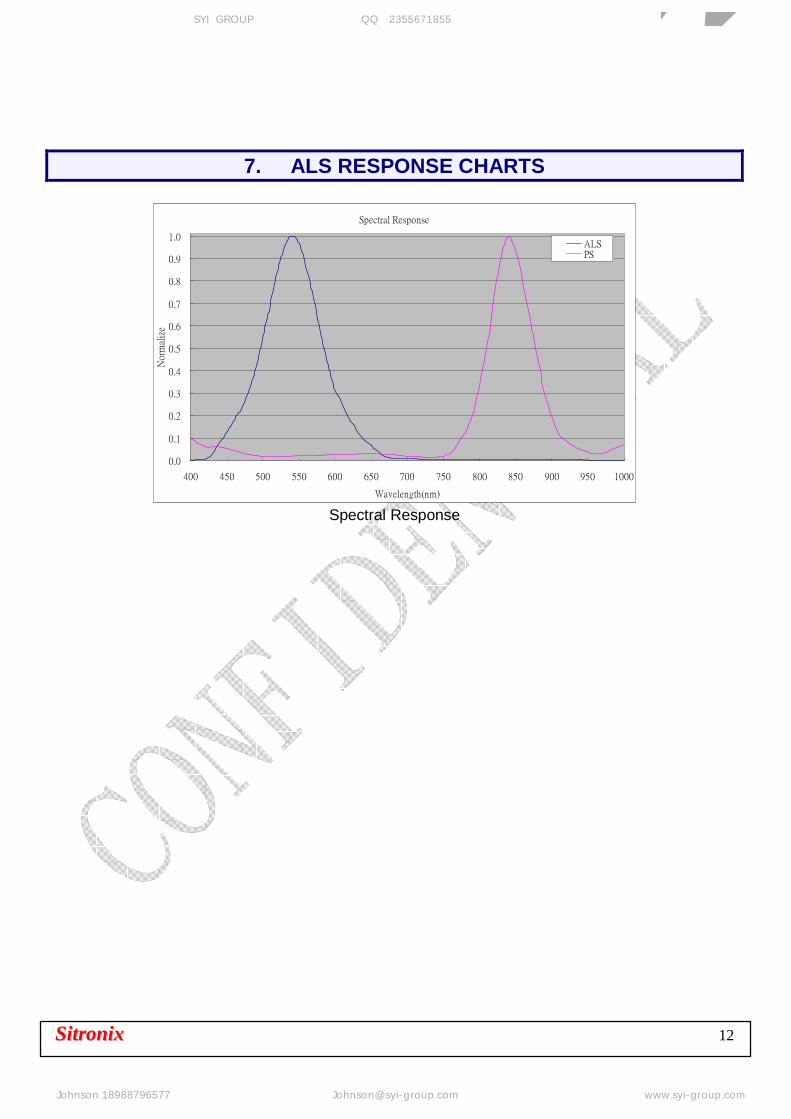
ILEDC Supply current of IR LED Note 1 100 mA ISD Shutdown current VDD=2.8V, 01h=09h=0x01 1 µA λp1 Peak sensitivity wavelength for ALS Note 2 550 nm λp2 Peak sensitivity wavelength for PS Note 2 850 nm
DarkData ALS Dark offset VDD=2.8V, 01h=0xC4h 0 1 Counts
Data/Data ALS Count Output Variation VDD=2.8V, 01h=0x00, White LED 224 280 336 Counts
PROXData Proximity Measurement Result VDD=2.8V, 09h=0x00, 850nm IR-LED 97 121 145 Counts
VIH Logic high, I2C VDD=2.8V 1.5 VDD V VIL Logic low, I2C VDD=2.8V — 0.4 V
— Detectable intensity — 57671 Lux
Note 1: Power supply (VAnode) is 2.8V and 01h=0x00, 09h=0x00 with RL = 0Ω (RL will be stated in sec. 12) Note 2: Power supply (VDD) is 2.8V, halogen lamp light source and room temperature is 25.
芯扬国际(香港)有限公司 SYI GROUP 企业QQ:2355671855 专业传感器供应商
Johnson 18988796577 [email protected] www.syi-group.com
SSiittrroonniixx 6
55..22 TTiimmiinngg CChhaarrtt
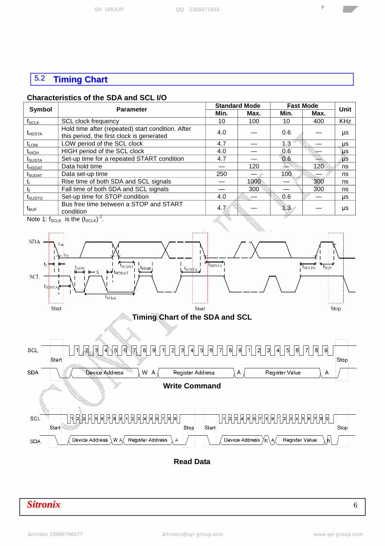
Characteristics of the SDA and SCL I/O Standard Mode Fast Mode Symbol Parameter Min. Max. Min. Max. Unit
fSCLK SCL clock frequency 10 100 10 400 KHz
tHDSTA Hold time after (repeated) start condition. After this period, the first clock is generated 4.0 — 0.6 — µs
tLOW LOW period of the SCL clock 4.7 — 1.3 — µs tHIGH HIGH period of the SCL clock 4.0 — 0.6 — µs tSUSTA Set-up time for a repeated START condition 4.7 — 0.6 — µs tHDDAT Data hold time — 120 — 120 ns tSUDAT Data set-up time 250 — 100 — ns tr Rise time of both SDA and SCL signals — 1000 — 300 ns tf Fall time of both SDA and SCL signals — 300 — 300 ns tSUSTO Set-up time for STOP condition 4.0 — 0.6 — µs
tBUF Bus free time between a STOP and START condition
4.7 — 1.3 — µs
Note 1: fSCLK is the (tSCLK)-1.
Timing Chart of the SDA and SCL
Write Command
Read Data
芯扬国际(香港)有限公司 SYI GROUP 企业QQ:2355671855 专业传感器供应商
Johnson 18988796577 [email protected] www.syi-group.com

SSiittrroonniixx 7
Sequential Read Data
6. PRINPICLE OF OPERATION Digital Interface STK3171-018 contains an eight 8-bit registers accessed via the I2C bus. All operations can be controlled by the command register. The sample command structure makes the user easy to program the operation setting and latch the light data from STK3171-018. In timing chart, it is STK3171-018 command format description for reading and writing operation between the host and STK3171-018. Slave Address STK3171-018 provides the fixed slave address, 0x90. In following table, it describes the command setting. ID Address COMMAND ADDRESS OPERATION
0x90 Write Command to STK3171-018 0x90 0x91 Read Data form STK3171-018
Function Description In the following table, there are 12 registers that are available in the STK3171-018. The STK3171-018 has 16-bit resolution for ALS. The host first reads the data from the 0x02 register data and then reads the 0x03 register data to complete the word mode data collection. The STK3171-018 has 8-bit resolution for PS. The PS data register is in the register 0x0A. The following table summarizes these functions.
BIT ADDR REG NAME 7 6 5 4 3 2 1 0
Default
01h ALS CMD Reserved
GAIN0_ALS
0 0 IT1_ALS
IT0_ALS
INT_ ALS
SD_ALS 01h
02h ALS DT1 DT15_ ALS
DT14_ ALS
DT13_ ALS
DT12_ ALS
DT11_ ALS
DT10_ ALS
DT9_ ALS
DT8_ALS
00h
03h ALS DT2 DT7_ ALS
DT6_ ALS
DT5_ ALS
DT4_ ALS
DT3_ ALS
DT2_ ALS
DT1_ ALS
DT0_ALS 00h
04h ALS THDH1
THDH15_ALS
THDH14_ ALS
THDH13_ ALS
THDH12_ ALS
THDH11_ ALS
THDH10_ ALS
THDH8_ ALS
THDH7 _ ALS
FFh
05h ALS THDH2
THDH7 _ALS
THDH6 _ ALS
THDH5 _ ALS
THDH4 _ ALS
THDH3_ ALS
THDH2 _ ALS
THDH1_ ALS
THDH0 _ ALS
FFh
06h ALS THDL1
THDL15_ ALS
THDL14_ ALS
THDL13_ ALS
THDL12_ ALS
THDL11_ ALS
THDL10_ ALS
THDL9_ ALS
THDL8 _ ALS 00h
07h ALS THDL2
THDL7 _ ALS
THDL6 _ ALS
THDL5 _ ALS
THDL4_ ALS
THDL3 _ ALS
THDL2 _ ALS
THDL1_ ALS
THDL0 _ ALS
00h
08h STA TUS ID1 ID0 FLG_PS FLG_ ALS 0 0 0 0 00h
09h PS CMD INT_CTRL
SLP1_PS
SLP0_PS
IRDR_ PS
IT1_PS IT0_PS INT_PS SD_PS 01h
0Ah PS DT DT7_PS DT6_PS DT5_PS DT4_PS DT3_PS DT2_PS DT1_PS DT0_PS 00h
0Bh PS THDH THDH7_PS
THDH6_PS
THDH5_PS
THDH4_PS
THDH3_PS
THDH2_PS
THDH_PS
THDH0_PS
FFh
0Ch PS THDL THDL7_PS
THDL6_PS
THDL5_PS
THDL4_PS
THDL3_PS
THDL2_PS
THDL1_PS
THDL0_ PS 00h
芯扬国际(香港)有限公司 SYI GROUP 企业QQ:2355671855 专业传感器供应商
Johnson 18988796577 [email protected] www.syi-group.com
SSiittrroonniixx 8
80h SW Reset SWRst7 SWRst6 SWRst5 SWRst4 SWRst3 SWRst2 SWRst1 SWRst0 00h 82h PS Gain GC_PS3 GC_PS2 GC_PS1 GC_PS0 PS_GS3 PS_ GS2 PS_ GS1 PS_ GS0 x8h
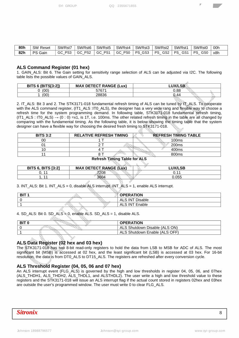
ALS Command Register (01 hex) 1. GAIN_ALS: Bit 6. The Gain setting for sensitivity range selection of ALS can be adjusted via I2C. The following table lists the possible values of GAIN_ALS.
BITS 6 (BITS[3:2]) MAX DETECT RANGE (Lux) LUX/LSB 0 (00) 57671 0.88 1 (00) 28836 0.44
2. IT_ALS: Bit 3 and 2. The STK3171-018 fundamental refresh timing of ALS can be tuned by IT_ALS. To cooperate with the ALS command register, (IT1_ALS :IT0_ALS), the designer has a very wide rang and flexible way to choose a refresh time for the system programming demand. In following table, STK3171-018 fundamental refresh timing, (IT1_ALS : IT0_ALS) → (0 : 0) =x1, is 1T, i.e. 100ms. The other related refresh timing in the table are all changed by comparing with the fundamental timing. As the following table, it is below showing the timing table that the system designer can have a flexible way for choosing the desired fresh timing to STK3171-018.
BITS 3:2 RELATIVE REFRESH TIMING REFRESH TIMING TABLE 00 1 T 100ms 01 2 T 200ms 10 4 T 400ms 11 8 T 800ms
Refresh Timing Table for ALS
BITS 6, BITS [3:2] MAX DETECT RANGE (Lux) LUX/LSB 0, 11 7208 0.11 1, 11 3604 0.055
3. INT_ALS: Bit 1. INT_ALS = 0, disable ALS interrupt. INT_ALS = 1, enable ALS interrupt.
BIT 1 OPERATION 0 ALS INT Disable 1 ALS INT Enable
4. SD_ALS: Bit 0. SD_ALS = 0, enable ALS. SD_ALS = 1, disable ALS.
BIT 0 OPERATION 0 ALS Shutdown Disable (ALS ON) 1 ALS Shutdown Enable (ALS OFF)
ALS Data Register (02 hex and 03 hex) The STK3171-018 has two 8-bit read-only registers to hold the data from LSB to MSB for ADC of ALS. The most significant bit (MSB) is accessed at 02 hex, and the least significant bit (LSB) is accessed at 03 hex. For 16-bit resolution, the data is from DT0_ALS to DT15_ALS. The registers are refreshed after every conversion cycle. ALS Threshold Register (04, 05, 06 and 07 hex) An ALS interrupt event (FLG_ALS) is governed by the high and low thresholds in register 04, 05, 06, and 07hex (ALS_THDH1, ALS_THDH2, ALS_THDL1, and ALSTHDL2). The user write a high and low threshold value to these registers and the STK3171-018 will issue an ALS interrupt flag if the actual count stored in registers 02hex and 03hex are outside the user’s programmed window. The user must write 0 to clear FLG_ALS.
芯扬国际(香港)有限公司 SYI GROUP 企业QQ:2355671855 专业传感器供应商
Johnson 18988796577 [email protected] www.syi-group.com

SSiittrroonniixx 9
Status Register (08 hex) 1. ID number; Bit 7 and 6. The ID number is 0b00 for STK3171-018. This registers is read only. 2. PS Interrupt flag; Bit 5. This is the status bit of the interrupt for PS. The bit is set to logic high when the interrupt thresholds have been triggered, and logic low when not yet triggered. Once triggered, INT pin stays low and the status bit stays high. Both interrupt pin and the status bit are cleared by writing “0”. BIT 5 OPERATION 0 Interrupt is cleared or not triggered yet 1 Interrupt is triggered 3. ALS Interrupt flag; Bit 4. This is the status bit of the interrupt for ALS. The bit is set to logic high when the interrupt thresholds have been triggered, and logic low when not yet triggered. Once triggered, INT pin stays low and the status bit stays high. Both interrupt pin and the status bit are cleared by writing “0”. BIT 4 OPERATION 0 Interrupt is cleared or not triggered yet 1 Interrupt is triggered 4. Reserved for engineering mode BITS 3:0 OPERATION 0000 To keep these bits be 0, don’t use these bits SW-Reset Register (80 hex) The STK3171-018 has internal Power ON reset. But it is recommended to do SW-Reset after Power ON by writing any value to SW-Reset register (ex: 0x80h=0x01h). SW-Reset register will be auto cleared when reading this byte. PS Gain Control Register (82 hex) 1. GC_PS: The setting is trimmed under test mode. Please keep the GC_PS trimming setting in application. BITS 7:4 GC_PS[3:0] 2. PS_ Gain Setting: Available setting is as below. The other PS Gain setting is not available. BITS 3:0 PS_GS[3:0] 0101 PS Gain x 4 1001 PS Gain x 8 1101 PS Gain x 16
芯扬国际(香港)有限公司 SYI GROUP 企业QQ:2355671855 专业传感器供应商
Johnson 18988796577 [email protected] www.syi-group.com
SSiittrroonniixx 10
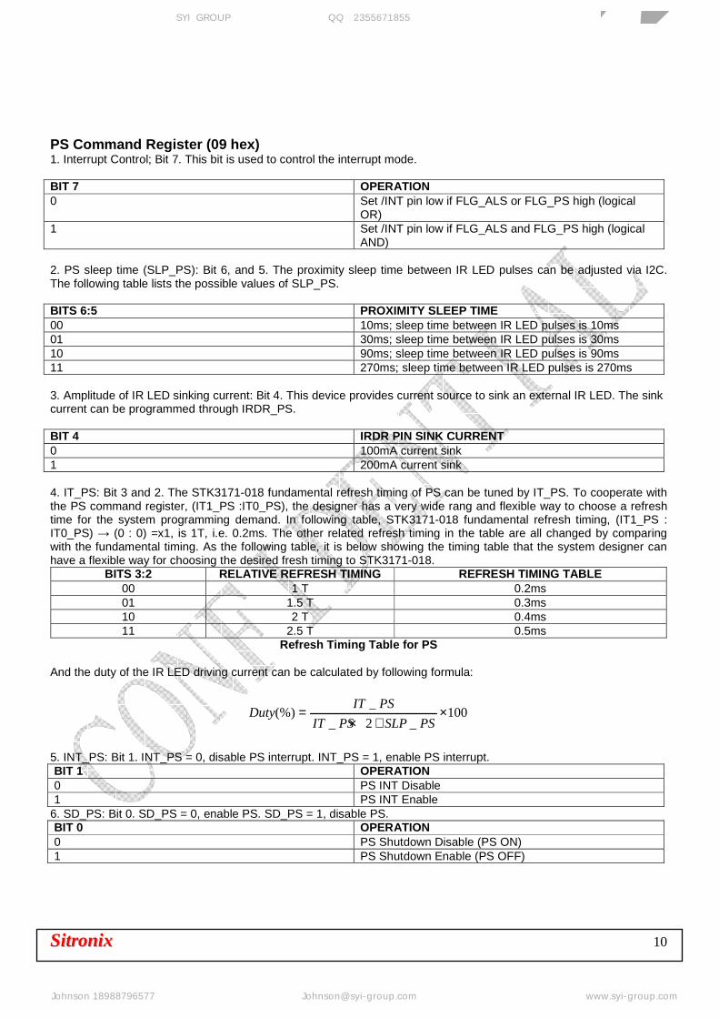
PS Command Register (09 hex) 1. Interrupt Control; Bit 7. This bit is used to control the interrupt mode. BIT 7 OPERATION 0 Set /INT pin low if FLG_ALS or FLG_PS high (logical
OR) 1 Set /INT pin low if FLG_ALS and FLG_PS high (logical
AND) 2. PS sleep time (SLP_PS): Bit 6, and 5. The proximity sleep time between IR LED pulses can be adjusted via I2C. The following table lists the possible values of SLP_PS. BITS 6:5 PROXIMITY SLEEP TIME 00 10ms; sleep time between IR LED pulses is 10ms 01 30ms; sleep time between IR LED pulses is 30ms 10 90ms; sleep time between IR LED pulses is 90ms 11 270ms; sleep time between IR LED pulses is 270ms 3. Amplitude of IR LED sinking current: Bit 4. This device provides current source to sink an external IR LED. The sink current can be programmed through IRDR_PS. BIT 4 IRDR PIN SINK CURRENT 0 100mA current sink 1 200mA current sink 4. IT_PS: Bit 3 and 2. The STK3171-018 fundamental refresh timing of PS can be tuned by IT_PS. To cooperate with the PS command register, (IT1_PS :IT0_PS), the designer has a very wide rang and flexible way to choose a refresh time for the system programming demand. In following table, STK3171-018 fundamental refresh timing, (IT1_PS : IT0_PS) → (0 : 0) =x1, is 1T, i.e. 0.2ms. The other related refresh timing in the table are all changed by comparing with the fundamental timing. As the following table, it is below showing the timing table that the system designer can have a flexible way for choosing the desired fresh timing to STK3171-018.
BITS 3:2 RELATIVE REFRESH TIMING REFRESH TIMING TABLE 00 1 T 0.2ms 01 1.5 T 0.3ms 10 2 T 0.4ms 11 2.5 T 0.5ms
Refresh Timing Table for PS
And the duty of the IR LED driving current can be calculated by following formula:
100_2_
_(%) ×
+×=
PSSLPPSIT
PSITDuty
5. INT_PS: Bit 1. INT_PS = 0, disable PS interrupt. INT_PS = 1, enable PS interrupt. BIT 1 OPERATION 0 PS INT Disable 1 PS INT Enable
6. SD_PS: Bit 0. SD_PS = 0, enable PS. SD_PS = 1, disable PS. BIT 0 OPERATION 0 PS Shutdown Disable (PS ON) 1 PS Shutdown Enable (PS OFF)
芯扬国际(香港)有限公司 SYI GROUP 企业QQ:2355671855 专业传感器供应商
Johnson 18988796577 [email protected] www.syi-group.com
SSiittrroonniixx 11
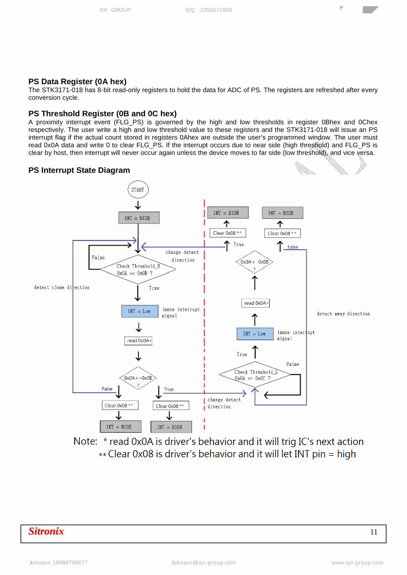
PS Data Register (0A hex) The STK3171-018 has 8-bit read-only registers to hold the data for ADC of PS. The registers are refreshed after every conversion cycle. PS Threshold Register (0B and 0C hex) A proximity interrupt event (FLG_PS) is governed by the high and low thresholds in register 0Bhex and 0Chex respectively. The user write a high and low threshold value to these registers and the STK3171-018 will issue an PS interrupt flag if the actual count stored in registers 0Ahex are outside the user’s programmed window. The user must read 0x0A data and write 0 to clear FLG_PS. If the interrupt occurs due to near side (high threshold) and FLG_PS is clear by host, then interrupt will never occur again unless the device moves to far side (low threshold), and vice versa. PS Interrupt State Diagram
芯扬国际(香港)有限公司 SYI GROUP 企业QQ:2355671855 专业传感器供应商
Johnson 18988796577 [email protected] www.syi-group.com
SSiittrroonniixx 12
7. ALS RESPONSE CHARTS
Spectral Response
0.0
0.1
0.2
0.3
0.4
0.5
0.6
0.7
0.8
0.9
1.0
400 450 500 550 600 650 700 750 800 850 900 950 1000
Wavelength(nm)
Nor
mal
ize
ALSPS
Spectral Response
芯扬国际(香港)有限公司 SYI GROUP 企业QQ:2355671855 专业传感器供应商
Johnson 18988796577 [email protected] www.syi-group.com

SSiittrroonniixx 13
8. ALS DYNAMIC RANGE
ALS Dynamic Range
芯扬国际(香港)有限公司 SYI GROUP 企业QQ:2355671855 专业传感器供应商
Johnson 18988796577 [email protected] www.syi-group.com
SSiittrroonniixx 14
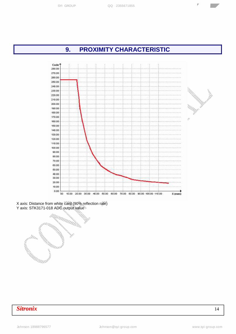
9. PROXIMITY CHARACTERISTIC
X axis: Distance from white card (90% reflection rate) Y axis: STK3171-018 ADC output value
芯扬国际(香港)有限公司 SYI GROUP 企业QQ:2355671855 专业传感器供应商
Johnson 18988796577 [email protected] www.syi-group.com
SSiittrroonniixx 15
芯扬国际(香港)有限公司 SYI GROUP 企业QQ:2355671855 专业传感器供应商
Johnson 18988796577 [email protected] www.syi-group.com

SSiittrroonniixx 16
10. PACKAGE OUTLINE TOP VIEW
SIDE VIEW
BOTTOM VIEW
芯扬国际(香港)有限公司 SYI GROUP 企业QQ:2355671855 专业传感器供应商
Johnson 18988796577 [email protected] www.syi-group.com
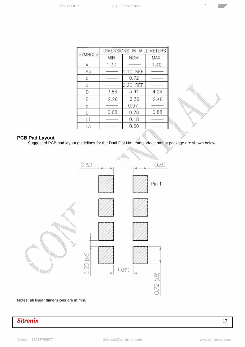
SSiittrroonniixx 17
PCB Pad Layout Suggested PCB pad layout guidelines for the Dual Flat No-Lead surface mount package are shown below.
Notes: all linear dimensions are in mm.
芯扬国际(香港)有限公司 SYI GROUP 企业QQ:2355671855 专业传感器供应商
Johnson 18988796577 [email protected] www.syi-group.com

SSiittrroonniixx 18
11. TAPE & REEL Unit: mm
芯扬国际(香港)有限公司 SYI GROUP 企业QQ:2355671855 专业传感器供应商
Johnson 18988796577 [email protected] www.syi-group.com
SSiittrroonniixx 19
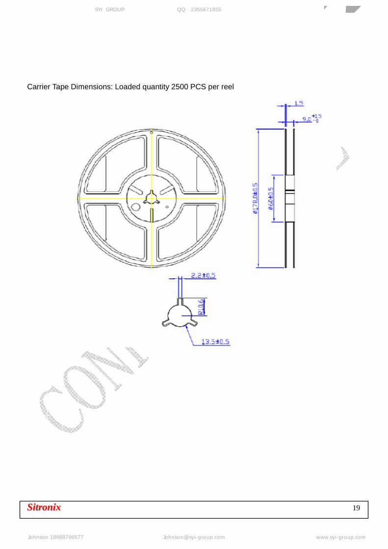
Carrier Tape Dimensions: Loaded quantity 2500 PCS per reel
芯扬国际(香港)有限公司 SYI GROUP 企业QQ:2355671855 专业传感器供应商
Johnson 18988796577 [email protected] www.syi-group.com
SSiittrroonniixx 20
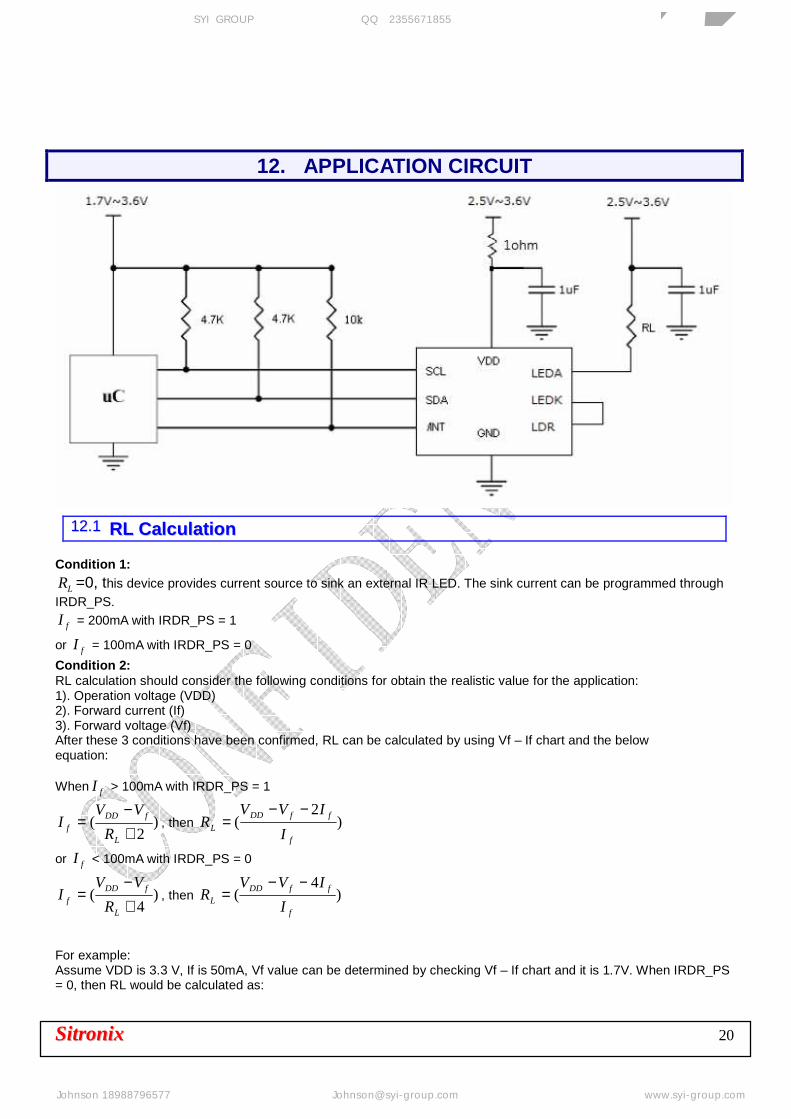
12. APPLICATION CIRCUIT
1122..11 RRLL CCaallccuullaattiioonn
Condition 1:
LR =0, this device provides current source to sink an external IR LED. The sink current can be programmed through IRDR_PS.
fI = 200mA with IRDR_PS = 1
or fI = 100mA with IRDR_PS = 0
Condition 2: RL calculation should consider the following conditions for obtain the realistic value for the application: 1). Operation voltage (VDD) 2). Forward current (If) 3). Forward voltage (Vf) After these 3 conditions have been confirmed, RL can be calculated by using Vf – If chart and the below equation:
When fI > 100mA with IRDR_PS = 1
)2
(+−
=L
fDDf R
VVI , then )
2(
f
ffDD
L I
IVVR
−−=
or fI < 100mA with IRDR_PS = 0
)4
(+−
=L
fDDf R
VVI , then )
4(
f
ffDDL I
IVVR
−−=
For example: Assume VDD is 3.3 V, If is 50mA, Vf value can be determined by checking Vf – If chart and it is 1.7V. When IRDR_PS = 0, then RL would be calculated as:
芯扬国际(香港)有限公司 SYI GROUP 企业QQ:2355671855 专业传感器供应商
Johnson 18988796577 [email protected] www.syi-group.com
SSiittrroonniixx 21
Ω=−−= 28)05.0
05.0*47.13.3(LR
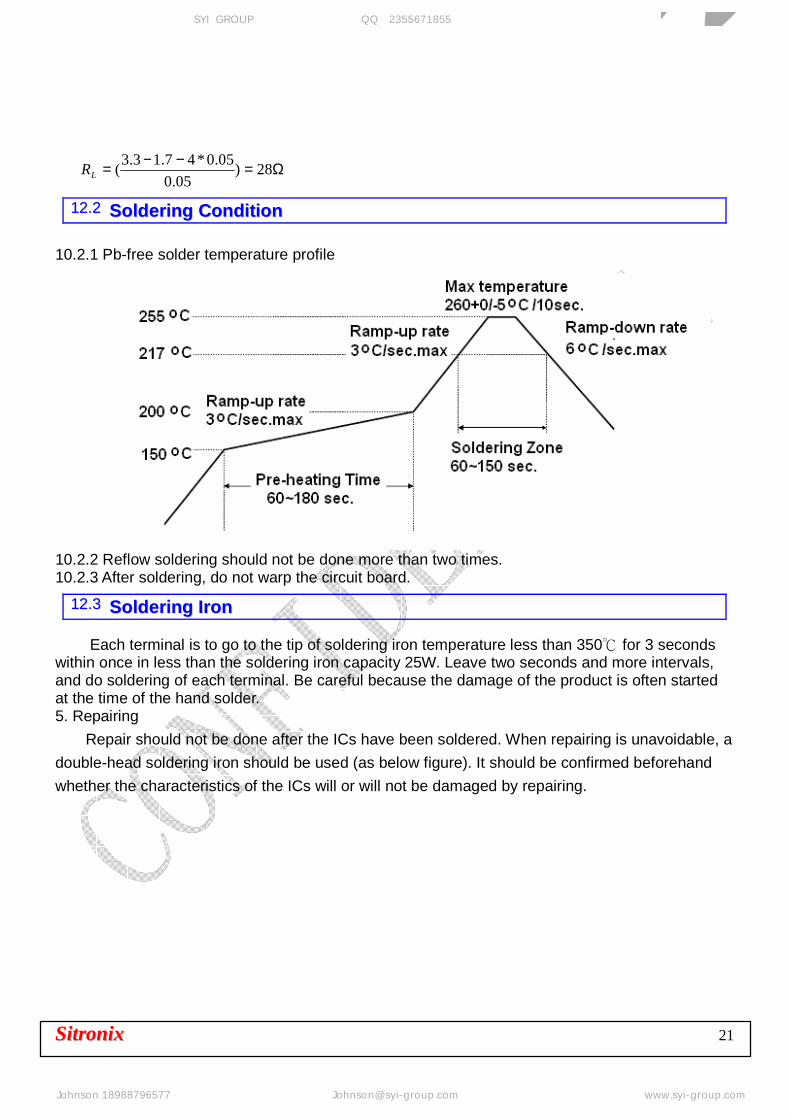
1122..22 SSoollddeerriinngg CCoonnddiittiioonn
10.2.1 Pb-free solder temperature profile
10.2.2 Reflow soldering should not be done more than two times. 10.2.3 After soldering, do not warp the circuit board.
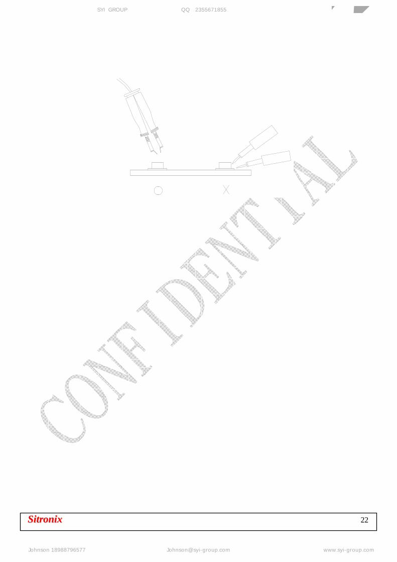
1122..33 SSoollddeerriinngg IIrroonn
Each terminal is to go to the tip of soldering iron temperature less than 350 for 3 seconds within once in less than the soldering iron capacity 25W. Leave two seconds and more intervals, and do soldering of each terminal. Be careful because the damage of the product is often started at the time of the hand solder. 5. Repairing
Repair should not be done after the ICs have been soldered. When repairing is unavoidable, a
double-head soldering iron should be used (as below figure). It should be confirmed beforehand
whether the characteristics of the ICs will or will not be damaged by repairing.
芯扬国际(香港)有限公司 SYI GROUP 企业QQ:2355671855 专业传感器供应商
Johnson 18988796577 [email protected] www.syi-group.com
SSiittrroonniixx 22
芯扬国际(香港)有限公司 SYI GROUP 企业QQ:2355671855 专业传感器供应商
Johnson 18988796577 [email protected] www.syi-group.com

SSiittrroonniixx 23
13. PRODUCT NAMING RULE
芯扬国际(香港)有限公司 SYI GROUP 企业QQ:2355671855 专业传感器供应商
Johnson 18988796577 [email protected] www.syi-group.com