Embed Size (px)
Citation preview

CATALOG 2014

Introduction
Piezoelectric Accelerometer Introduction
Industrial Piezoelectric Vibration Sensor
Mounting & Accessories
Raw cable
Cable assembly
Din rail interface unit : BNC & Switch
Boxes interface unit : BNC & Switch
Services
Appendix
GOAL : Be your European vibration Sensor Partner
VibraSens is a European company that designs and manufac-tures vibration instrumentations such as industrial piezoelectric accelerometers, vibration sensors, vibration transmitters, signal conditioners, junction boxes, low noise cable assemblies, con-nectors, accessories and calibration equipments.
MissionVibrasens’ mission is: • Be one of the European leaders in the manufacture and de-
sign of piezoelectric accelerometer and piezoelectric dy-namic pressure sensor.
• Offer innovative piezoelectric vibration sensor for niche market and harsh environment (700°C).
• Offer private labelling of our products for companies who want to outsource their piezoelectric accelerometer and pressure sensor manufacture.
• Be the ideal partner in terms of pricing, reliability and tech-nical support.
Industry servedOur piezoelectric accelerometers are used throughout the fol-lowing industry : Power generation (Gas turbine, Steam turbine, Wind turbine, Hydro generator), Petrochemical & Pipeline in-dustry, Offshore platform industry, General process industry, Research and development facilities, Metals & Mining, Pulp and paper, Waste water treatment, Research and development and many others.....
ApplicationsIndustrial piezoelectric accelerometers can sense vibrations in terms of acceleration, velocity and displacement for machines such as : Air compressors, Air handlers, Pulp and paper dryer sections, Conveyors, Cooling towers, Fans, Fourdriniers, Gear boxes, Motors, Press sections, Presses, Stamping, Pumps, Roll and process equipment, Spindles, ..
ExperienceWe have more than 20 years of experience in the piezoelectric accelerometer design, especially in harsh and high temperature environment (500°C, 700°C or even more).In order to maintain our international expertise we closely work with two university laboratories LCEP ( http://www.lcep.ens2m.fr ) and LPMO ( http://www.lpmo.edu ) based in Besançon and specialized in Piezoelectricity.We also have the chance to be located in a region where piezo-electricity, microtechnics, microelectronic, mechatronic, micro-sensors and precision are well known words. Besançon hosts one of the biggest microtechnology fair in Europe ( http://www.micronora.com ) devoted to microtechnology and strong of 850 exhibitors from 25 countries.All this friendly environment strengthens our knowledge and gives our company a competitive advantage in the piezoelectric vibration sensor technology.
TechnologyWith advanced product development and manufacturing facili-ties in Besançon-France, VibraSens has the skills, experience and resources to provide the products and services that will ful-fill your requirements.A modern production facility exclusively engaged in the design and manufacture of piezoelectric vibration transducers, piezo-electric pressure sensor and vibration instrumentations help us to maintain a high quality level in our core business.Our manufacturing and test equipment ranges from basic preci-sion machinery for providing high quality sensor components,
1
2
3
4
5
6
7
8
9
10
www.vibrasens.com
2
Intr
oduc
tion
1
to custom-built machinery specifically designed for piezoelectric vi-bration sensor fabrication. During the years of development we have also built some specifically design systems to test our range of piezoelectric accelerometer. We have developed using ®Labview (National Instrument Trademark) a completely automated shaker test system to check the sensitivity and frequency response (up to 10 kHz) of our piezoelectric vibration sensors.Our controlled process includes laser and microplasma welding, he-lium leak tester, resistance welding, temperature cycling, high em-perature brazing. All those processes and others are strictly controlled by our process specification document.We closely work with one of the best European company specialized in the manufacturing of hybrid circuit for the sensor industry. With this partnership, we are sure to stay ahead of this technology for the years to come.
Why should you buy from us:We are focussed on the manufacture and design of piezoelectric vi-bration sensor. We could offer you the best quality price performance on the market.We invest heavily in our core business and keep all of our products up to state of the art technology.To better suit your market, we offer private labeling for all of our product line with two digits modifications in our part number.Whatever your market is, condition monitoring, balancing, vibration diagnostic services company, we will be happy to serve you and share our extensive expertise. We are looking forward to being your vibra-tion sensor partner.
www.vibrasens.com
3
Piezoelectric Accelerom
eter Introduction
2
Piezoelectric Accelerometer SelectionBecause they cover the broadest range of applications, piezoelectric accelerometers are among the most versatile.Their main characteristics cover the range:• temperature from cryogenic to +800 °C• frequency from 0.1 Hz to 50 kHz • resolution from 1 ug to 100 000 g
Their physical characteristics cover the range:• Connector or integral cable • MIL, industrial, RF connectors • Few grammes to 200 grammes• Stainless stee, aluminum or titanium material• Hermetically or epoxy sealed
In a first approach, piezoelectric sensors can be distinguished by:• Output (AC or DC, acceleration, velocity or displacement out-
put)• Piezoelectric material (ceramic, quartz, tourmaline,...) • Transmission type, ®ICP, current, 4-20mA,....• Stainless steel, aluminum or titanium material• Hermetically or epoxy sealed
The table below sums up technology commercially available.
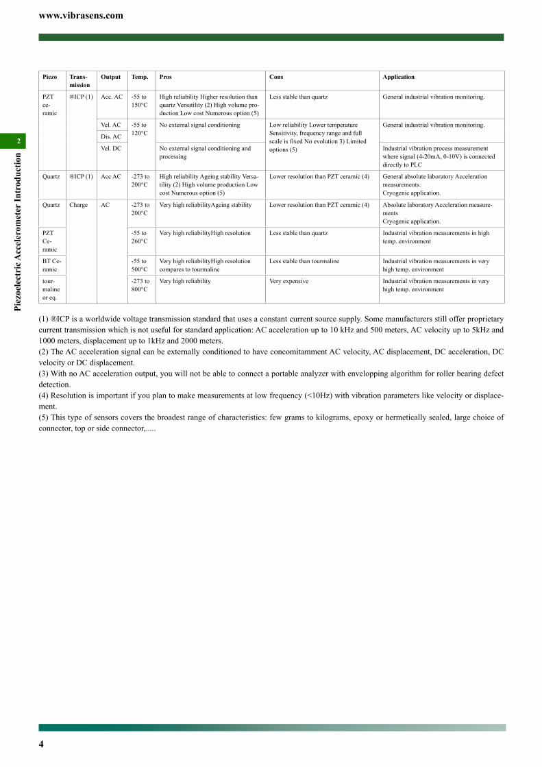
Accelerometer Technology SelectionIf you want to assess the motion of an object then you need a sen-sor to do it. There are many styles like for example the eddy current probe, the velocimeter, the laser or the accelerometer. All have their output proportional to the motion of the object let it be acceleration, velocity or displacement. All have their own characteristic in terms of temperature, frequency response, linearity, sensitivity, etc. The accel-erometer have proved to be successful in many applications.Accelerometer exhibits 3 technologies:• piezoelectric• capacitive• piezoresistive
Their intrinsic characteristics are sum up in the table below:
Piez
oele
ctri
c
Cap
aciti
ve
Piez
ores
istiv
e
Frequency 0.2 Hz to 50 kHz
DC to few hun-dreds hertz
DC to few thousands hertz
Shock resis-tance
<100 000 g < 1000g > 100 000g
Temperatu -273°C to 800°C
-55°C to +120°C -55°C to +120°C
Applications Vibrations Vibrations at low frequency andmo-tion with no shock
Vibrations at low frequency and motion in presence of very high shock
VibraSens designs and manufactures piezoelectric accelerometer only. We can also manufacture using commercially available chip, capacitive or piezoresistive accelerometers.
Contents
Accelerometer Technology Selection ............................................3
Piezoelectric Accelerometer Selection ..........................................3
www.vibrasens.com
4
Piez
oele
ctri
c Acc
eler
omet
er In
trod
uctio
n
2
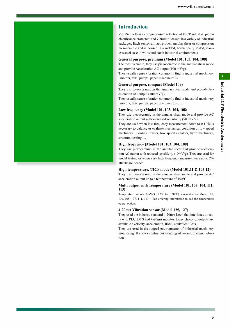
Piezo Trans-mission
Output Temp. Pros Cons Application
PZT ce-ramic
®ICP (1) Acc. AC -55 to 150°C
High reliability Higher resolution than quartz Versatility (2) High volume pro-duction Low cost Numerous option (5)
Less stable than quartz General industrial vibration monitoring.
Vel. AC -55 to 120°C
No external signal conditioning Low reliability Lower temperature Sensitivity, frequency range and full scale is fixed No evolution 3) Limited options (5)
General industrial vibration monitoring.
Dis. AC
Vel. DC No external signal conditioning and processing
Industrial vibration process measurement where signal (4-20mA, 0-10V) is connected directly to PLC
Quartz ®ICP (1) Acc AC -273 to 200°C
High reliability Ageing stability Versa-tility (2) High volume production Low cost Numerous option (5)
Lower resolution than PZT ceramic (4) General absolute laboratory Acceleration measurements.Cryogenic application.
Quartz Charge AC -273 to 200°C
Very high reliabilityAgeing stability Lower resolution than PZT ceramic (4) Absolute laboratory Acceleration measure-mentsCryogenic application.
PZT Ce-ramic
-55 to 260°C
Very high reliabilityHigh resolution Less stable than quartz Industrial vibration measurements in high temp. environment
BT Ce-ramic
-55 to 500°C
Very high reliabilityHigh resolution compares to tourmaline
Less stable than tourmaline Industrial vibration measurements in very high temp. environment
tour-maline or eq.
-273 to 800°C
Very high reliability Very expensive Industrial vibration measurements in very high temp. environment
(1) ®ICP is a worldwide voltage transmission standard that uses a constant current source supply. Some manufacturers still offer proprietary current transmission which is not useful for standard application: AC acceleration up to 10 kHz and 500 meters, AC velocity up to 5kHz and 1000 meters, displacement up to 1kHz and 2000 meters.(2) The AC acceleration signal can be externally conditioned to have concomitamment AC velocity, AC displacement, DC acceleration, DC velocity or DC displacement.(3) With no AC acceleration output, you will not be able to connect a portable analyzer with envelopping algorithm for roller bearing defect detection.(4) Resolution is important if you plan to make measurements at low frequency (<10Hz) with vibration parameters like velocity or displace-ment.(5) This type of sensors covers the broadest range of characteristics: few grams to kilograms, epoxy or hermetically sealed, large choice of connector, top or side connector,.....
www.vibrasens.com
5
Industrial ICP Piezoelectric A
ccelerometer
3
IntroductionVibraSens offers a comprehensive selection of ®ICP industrial piezo-electric accelerometers and vibration sensors in a variety of industrial packages. Each sensor utilizes proven annular shear or compression piezoceramic and is housed in a welded, hermetically sealed, stain-less steel case to withstand harsh industrial environments
General purpose, premium (Model 101, 103, 104, 108)The most versatile, they use piezoceramic in the annular shear mode and provide Acceleration AC output (100 mV/g).They usually sense vibration commonly find in industrial machinery : motors, fans, pumps, paper machine rolls, ....
General purpose, compact (Model 109)They use piezoceramic in the annular shear mode and provide Ac-celeration AC output (100 mV/g)..They usually sense vibration commonly find in industrial machinery : motors, fans, pumps, paper machine rolls, ....
Low frequency (Model 101, 103, 104, 108)They use piezoceramic in the annular shear mode and provide AC acceleration output with increased sensitivity (500mV/g).They are used when low frequency measurement down to 0.1 Hz is necessary to balance or evaluate mechanical condition of low speed machinery : cooling towers, low speed agitators, hydromachinery, structural testing, ...
High frequency (Model 101, 103, 104, 108)They use piezoceramic in the annular shear and provide accelera-tion AC output with reduced sensitivity (10mV/g). They are used for modal testing or when very high frequency measurements up to 20-30kHz are needed.
High temperature, ©ICP mode (Model 101.11 & 103.12)They use piezoceramic in the annular shear mode and provide AC acceleration output up to a temperature of 150°C.
Multi output with Temperature (Model 101, 103, 104, 111, 113)Temperature output (10mV/°C, +2°C to +120°C) is available for Model 101, 103, 105, 107, 111, 113 . See ordering information to add the temperature output option.
4-20mA Vibration sensor (Model 125, 127)They used the industry standard 4-20mA Loop that interfaces direct-ly with PLC, DCS and 4-20mA monitor. Large choice of outputs are availbale : velocity, acceleration, RMS, equivalent Peak.They are used in the rugged environments of industrial machinery monitoring. It allows continuous trending of overall machine vibra-tion.
Contents
Introduction ....................................................................................5
Most Popular Model ......................................................................6
®ICP Accelerometer Model 101 Premium, Top connector ........7
®ICP Accelerometer Model 109 Compact, Top connector .......11
®ICP Accelerometer Model 103 Premium, Side connector .....15
®ICP Accelerometer Model 104 Premium, Side connector .....19
®ICP Accelerometer Model 108 Premium, Top connector ......22
®ICP PiezoVelocity sensor Model 111 Top Connector..............25
®ICP PiezoVelocity sensor Model 113 Side Connector ............29
4-20 mA Vibration Sensor Model 125 Top Connector ..............33
4-20 mA Vibration Sensor Model 127 Side Connector .............37
OEM Piezoelectric AccelerometerModel 160 ............................40
®ICP Low cost triaxial accelerometer Model 131.....................42
®ICP Low cost triaxial accelerometer Model 132.....................44
www.vibrasens.com
6
Indu
stri
al IC
P Pi
ezoe
lect
ric A
ccel
erom
eter
3
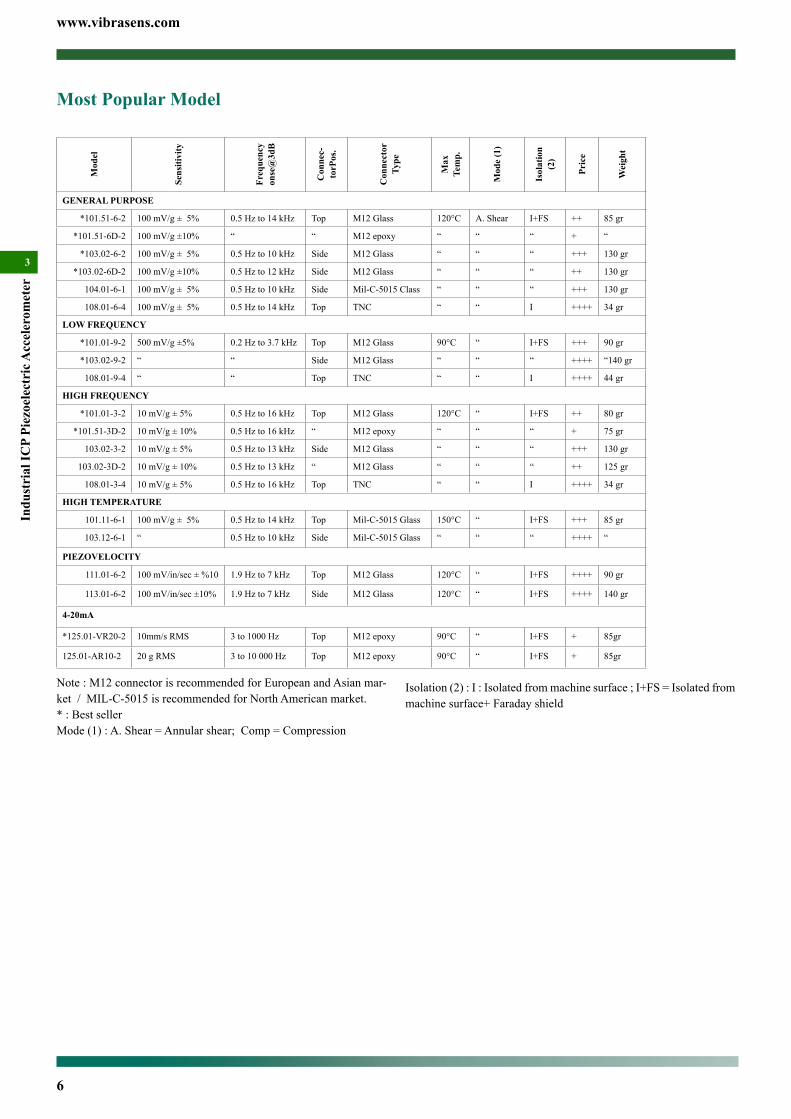
Most Popular ModelM
odel
Sens
itivi
ty
Freq
uenc
y on
se@
3dB
Con
nec-
torP
os.
Con
nect
or
Type
Max
Te
mp.
Mod
e (1
)
Isol
atio
n (2
)
Pric
e
Wei
ght
GENERAL PURPOSE
*101.51-6-2 100 mV/g ± 5% 0.5 Hz to 14 kHz Top M12 Glass 120°C A. Shear I+FS ++ 85 gr
*101.51-6D-2 100 mV/g ±10% “ “ M12 epoxy “ “ “ + “
*103.02-6-2 100 mV/g ± 5% 0.5 Hz to 10 kHz Side M12 Glass “ “ “ +++ 130 gr
*103.02-6D-2 100 mV/g ±10% 0.5 Hz to 12 kHz Side M12 Glass “ “ “ ++ 130 gr
104.01-6-1 100 mV/g ± 5% 0.5 Hz to 10 kHz Side Mil-C-5015 Class “ “ “ +++ 130 gr
108.01-6-4 100 mV/g ± 5% 0.5 Hz to 14 kHz Top TNC “ “ I ++++ 34 gr
LOW FREQUENCY
*101.01-9-2 500 mV/g ±5% 0.2 Hz to 3.7 kHz Top M12 Glass 90°C “ I+FS +++ 90 gr
*103.02-9-2 “ “ Side M12 Glass “ “ “ ++++ “140 gr
108.01-9-4 “ “ Top TNC “ “ I ++++ 44 gr
HIGH FREQUENCY
*101.01-3-2 10 mV/g ± 5% 0.5 Hz to 16 kHz Top M12 Glass 120°C “ I+FS ++ 80 gr
*101.51-3D-2 10 mV/g ± 10% 0.5 Hz to 16 kHz “ M12 epoxy “ “ “ + 75 gr
103.02-3-2 10 mV/g ± 5% 0.5 Hz to 13 kHz Side M12 Glass “ “ “ +++ 130 gr
103.02-3D-2 10 mV/g ± 10% 0.5 Hz to 13 kHz “ M12 Glass “ “ “ ++ 125 gr
108.01-3-4 10 mV/g ± 5% 0.5 Hz to 16 kHz Top TNC “ “ I ++++ 34 gr
HIGH TEMPERATURE
101.11-6-1 100 mV/g ± 5% 0.5 Hz to 14 kHz Top Mil-C-5015 Glass 150°C “ I+FS +++ 85 gr
103.12-6-1 “ 0.5 Hz to 10 kHz Side Mil-C-5015 Glass “ “ “ ++++ “
PIEZOVELOCITY
111.01-6-2 100 mV/in/sec ± %10 1.9 Hz to 7 kHz Top M12 Glass 120°C “ I+FS ++++ 90 gr
113.01-6-2 100 mV/in/sec ±10% 1.9 Hz to 7 kHz Side M12 Glass 120°C “ I+FS ++++ 140 gr
4-20mA
*125.01-VR20-2 10mm/s RMS 3 to 1000 Hz Top M12 epoxy 90°C “ I+FS + 85gr
125.01-AR10-2 20 g RMS 3 to 10 000 Hz Top M12 epoxy 90°C “ I+FS + 85gr
Note : M12 connector is recommended for European and Asian mar-ket / MIL-C-5015 is recommended for North American market.* : Best sellerMode (1) : A. Shear = Annular shear; Comp = Compression
Isolation (2) : I : Isolated from machine surface ; I+FS = Isolated from machine surface+ Faraday shield

www.vibrasens.com
7
Industrial ICP Piezoelectric A
ccelerometer
3
®ICP Accelerometer Model 101 Premium, Top connectorMain Characteristics• Annular shear mode• 10, 50, 100, 500 mV/g version availbale• -55°C to 150 °C (-67°F to 302°F)• Dual case isolation with Faraday shield• Submersible version (150 metres) with associated IP68 over-
molded cable• life time hermetic sealing warranty (M12/Mil glass seal con-
nector)
Competitive advantage• Compare to obsolete compression design, annular shear
piezoelectric sensors feature better frequency response, improved base strain, lower noise, smaller size, ther-mal transient imunity and insensitivity to cable motion. Annular shear mode is also less susceptible to transverse vi-brations and better immune to electronic saturation at high fre-quency.
• 80 g dynamic range (thanks to exceptional bias stability) at el-evated temperatures.
• Resistant to shock (magnet mounting) thanks to Jfet transistor input.
• ESD and reverse wiring protection.• The glass seal hermetic connector protects the piezoelectric discandtheelectronicfromharmfulenvironmentalinfluences,significantlyincreasingtheirreliabilityandlifetime.Associatedwith low cost IP68 overmolded M12 cable assembly it is a per-fect solution for submersible application down to 150 metres. Sensors with epoxy seal will always leak after few temperature cycles.
• M12 connector offers compatibility with numerous sensors used in automation. M12 overmolded cable assemblies are available from many cable manufacturers around the world. Mil cordset are expensive because they are only available from vibration sensor manufacturer.
DescriptionThe hermetic sealed industrial piezoelectric accelerometer model 101 is design to monitor the vibration in harsh industrial environment. It uses the industry standard ©ICP / ©IEPE / ©LIVM 2-wire voltage transmission technique with a 4 mA standard constant current supply. Signal ground is isolated from the mounting surface and outer case to prevent ground loops. Faraday shielding will limit sensitivity to EMC to a minimum. Annular shear mode design will prevent from thermal transient and from spurious signal from high transverse vibrations. Low noise electronic and a temperature compensated design will give you accurate result over the complete temperature range. Large choice of frequency range will help to fit almost every customer re-quirements. Low frequency accelerometers (A=9) incorporate a low-pass filter within the conditioning electronic. This filter attenuates the sensor mechanical resonance and the associated distortion and overload.
Typical applicationsVibrations measurement in the rugged environments of industrial ma-chinery monitoring. High frequency version monitor the vibration on roller bearing, pumps cavitation, .... Medium frequency version monitor overall vibration on pumps, motors, fans, ... Low frequency model is used in the petrochemical, machine tool, and paper indus-tries for monitoring of slow speed agitators, cooling towers, ... High temperature version is typically used where extra temperature protec-tion is needed, such as the dryer section of a paper machine.
Ordering information model 101To order, specify model number, options, accessories and suffix :
101.51- AA - B - TT - MM - HH - YY
Model 101.51-A-2 with overmolded IP 68 submersible M12 cable assembly
AA : Sensitivity3 : 10 mV/g ±5 % (high frequency)3D : 10 mV/g ±10 % (high frequecy)
5 : 50 mV/g ±5 % (high frequency)5D : 50 mV/g ±10 % (high frequency)
6 : 100 mV/g ±5 % (medium frequency, general purpose)6D : 100 mV/g ±10 % (medium frequency, general purpose)6Q : 100 mV/g ±15 % (medium frequency, general purpose)
9 : 500 mV/g ±5 % (low frequency down to 0.2 Hz)9D : 500 mV/g ±10 % (low frequency down to 0.2 Hz
Available suffix : N, negative polarityB : Connector
1 : MIL-C-5015, glass seal2 : M12 glass seal
B(CC-DD) Integral cable5 (CC-DD) : Integral cable7 (CC-DD) : Integral cable with sstl overbraid protection8 (CC-DD) : Integral cable with stainless steel protection conduit5, 7, 8 : epoxy seal.
CC : Cable Type01 : *Polyurethane cable (90°C)02 : *Teflon FEP Cable (200°C)03 : Radox cable (120°C, halogen free)
DD : length in metreTT : Temperature output.
omitted : no temperature outputT0 : 10 mV/°C. (range +2° to +120°C)Not available with Mil-C-5015 2 pins connector
MM : Machine threadomitted : no mounting stud will be shipped with the sensor.M6 : M6x1M7 : 1/4” 28 UNF 2AM8 : M8x1.25
HH : Housing threadH6 or omitted : M6x1 (China, Europe, India, South America, ...)H1 : M16x2 (quick mouting + 120° positioning) (Not stocked)H2 : Quick fit mounting (Not stocked)H7 : 1/4” 28 UNF-2A. (U.S.A., UK, ...)
YY : Agency Approvalomitted : no agency approval
www.vibrasens.com
8
Indu
stri
al IC
P Pi
ezoe
lect
ric A
ccel
erom
eter
3
...............................................................................................................0VDC at 0°CRange ....................................................................................................+2° to 120°C
ElectricalElectrical Grounding ....................................................... Isolated from machine ground................................................................................... Internal Faraday shielding (fig. 1)Isolation(Case to shield) ............................................................................100MΩMinCapacitance to ground ................................................................................... 70 pF NomOutput impedance ........................................................................................... 50ΩNomDC output bias, 4mA supply .........................................................12 VDC Nom (Fig 2)Residual noise (24°C) : A=3X
1 Hz to 25 kHz ......................................................................................... 300 ug rms1 Hz ................................................................................................................... 30 ug
Residual noise (24°C) : A=6X1 Hz to 25 kHz ........................................................................................ 300 ug rms1 Hz .................................................................................................................. 30 ug
Residual noise (24°C) : A=9X1 Hz to 25 kHz .......................................................................................... 25 ug rms1 Hz .................................................................................................................. 2.4 ug
Power requirements Constant current : +2 to +10mA DC...............................................................................................Voltage : +22 to +28 VDCProtection : Overvoltage ........................................................................................... Yes : Reverse polarity ..................................................................................... Yes
EnvironmentalTemperature, operating continuous : 101.01 & 101.51 (max. current =4mA)
A= 3X, 6X ...................................................................-55 to 120 °C (-65 to 250 °F)A=9X ..............................................................................-55 to 90 °C (-65 to 212 °F)
Temperature, operating continuous : 101.11 (max. current =4mA)A=6X, B=1 . ..................................................................-55 to 150°C (-65 to 302 °F)
Humidity / EnclosureB=1, 2 ................................................ Not affected, hermetically sealed, 1E-8torr.l/s B=5, 7, 8 ....................................................................................... IP68, epoxy sealed
Acceleration limit : Shock ...........................................................................5 000g peak : Continuous vibration.......................................................500g peakBase strain sensitivity ..................................................................... 0.0002 g pk/u strainTemp. transient sens. (3Hz, LLF, 20dB/dec) .....................................................5 mg/°C Acoustic sensitivity (164 dBSP) .......................................................................... 0.5 mg Electromagnetic sens. (50Hz, 0.03 T) .................................................................... 0.2 gMean time between failure (MTBF) ........................................................ 10 Years NomESD Protection ................................................................................................... > 40 VSafety ................................................................................EN 61010-1 and IEC 1010-1EMC emission ........................................................................EN 50081-1, EN 50081-2EMC immunity (1) ............................................................... EN 50082-1, EN 50082-2
PhysicalDimensions
B=1 .................................................................................................................. Fig. 1aB=2 ..................................................................................................................Fig. 1bB=5 ..................................................................................................................Fig. 1dB=7 .................................................................................................................. Fig. 1eB=8 ...................................................................................................................Fig. 1f
Design ............................................................................. Ceramic, annular shear modeWeight with connector
A=3..............................................................................................80 gr Nom (2.8 Oz)A=6 .............................................................................................85 gr Nom (3.0 Oz)A=9 .............................................................................................95 gr Nom (3.4 Oz)
ConnectorB=1 ................................................ MIL-C-5015 glass seal, Type MS3143 10SL-4PB=2 .......................................................................... M12 glass seal, IEC 60947-5-2
Material ...........................................................AISI 316L, DIN 1.4404 (Stainless steel)Housing thread ......................................................................................................Fig 1hMounting torque (M6, M7, M8 suffix) ............................................ 2,4 N.m (21 in-lbs)
Accessories, suppliedCalibration supplied...................................................................................................Sensitivity (5g, 160 Hz).................................................................................................... No frequency response
Accessories, not suppliedCable assembly B=1 (Mil connector)
Polyurethane cable .......................................................... 10.01-B22-A01-05-LengthFEP Teflon cable ............................................................. 10.01-B22-A01-02-Length
Cable assembly B=2 (M12 connector)Polyurethane cable ......................................................... 10.01-E02-A01-31-LengthFEP Teflon cable ............................................................. 10.01-E02-A01-02-LengthFor more cable option see Model 10.01 (specific cable harness).
Accessories, spares partMounting Stud with HH=H6
M6 machine thread ............................................................................ 191.01-06-06-11/4” 28 UNF machine thread ............................................................ 191.01-06-16-1
Y1 : Atex approved (July 2010)Special Engraving :
Add ZXX at the end of the part number.XX is a number supplied by VibraSens
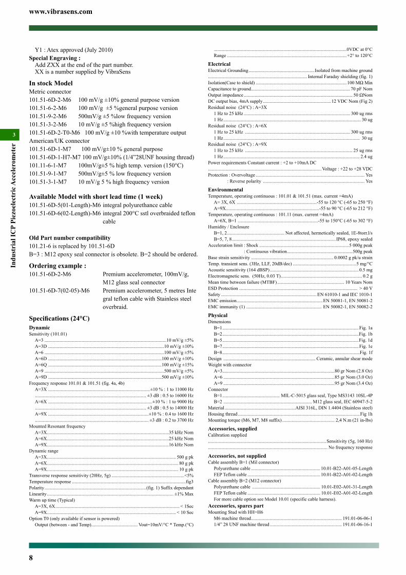
In stock ModelMetric connector101.51-6D-2-M6 100 mV/g ±10% general purpose version101.51-6-2-M6 100 mV/g ±5 %general purpose version101.51-9-2-M6 500mV/g ±5 %low frequency version101.51-3-2-M6 10 mV/g ±5 %high frequency version101.51-6D-2-T0-M6 100 mV/g ±10 %with temperature outputAmerican/UK connector101.51-6D-1-M7 100 mV/g±10 % general purpose101.51-6D-1-H7-M7 100 mV/g±10% (1/4”28UNF housing thread)101.11-6-1-M7 100mV/g±5 % high temp. version (150°C)101.51-9-1-M7 500mV/g±5 % low frequency version101.51-3-1-M7 10 mV/g 5 % high frequency version
Available Model with short lead time (1 week)101.51-6D-5(01-Length)-M6 integral polyurethance cable101.51-6D-6(02-Length)-M6 integral 200°C sstl overbraided teflon cable
Old Part number compatibility101.21-6 is replaced by 101.51-6DB=3 : M12 epoxy seal connector is obsolete. B=2 should be ordered.
Ordering example : 101.51-6D-2-M6 Premium accelerometer, 100mV/g, M12 glass seal connector101.51-6D-7(02-05)-M6 Premium accelerometer, 5 metres Inte gral teflon cable with Stainless steel overbraid.
Specifications (24°C)DynamicSensitivity (101.01)
A=3 ......................................................................................................10 mV/g ±5%A=3D .................................................................................................10 mV/g ±10%A=6 ....................................................................................................100 mV/g ±5%A=6D ...............................................................................................100 mV/g ±10%A=6Q ...............................................................................................100 mV/g ±15%A=9 ....................................................................................................500 mV/g ±5%A=9D ...............................................................................................500 mV/g ±10%
Frequency response 101.01 & 101.51 (fig. 4a, 4b)A=3X .....................................................................................±10 % : 1 to 11000 Hz ............................................................................................. ±3 dB : 0.5 to 16000 HzA=6X .......................................................................................±10 % : 1 to 9000 Hz ............................................................................................. ±3 dB : 0.5 to 14000 HzA=9X ....................................................................................±10 % : 0.4 to 1600 Hz ............................................................................................... ±3 dB : 0.2 to 3700 Hz
Mounted Resonant frequencyA=3X ......................................................................................................35 kHz NomA=6X ......................................................................................................25 kHz NomA=9X ......................................................................................................16 kHz Nom
Dynamic rangeA=3X ............................................................................................................ 500 g pkA=6X .............................................................................................................. 80 g pkA=9X .............................................................................................................. 10 g pk
Transverse response sensitivity (20Hz, 5g) .............................................................<5%Temperature response ...............................................................................................fig3Polarity .....................................................................................(fig. 1) Suffix dependantLinearity .......................................................................................................... ±1% MaxWarm up time (Typical)
A=3X, 6X ........................................................................................................ < 1SecA=9X ............................................................................................................ < 10 Sec
Option T0 (only available if sensor is powered)Output (between - and Temp)....................................... Vout=10mV/°C * Temp.(°C)
www.vibrasens.com
9
Industrial ICP Piezoelectric A
ccelerometer
3
22Hex
Master key
2 1
43
20
.79
[]
2 0
.79[ ]
46.5
1.83
[]
1 2M
ReceptacleM12 − IEC 60947−5−2
21.3
.84[ ]
Model Number Pin 1 Pin 2 Pin 3 Pin 4
Standard, no option NC NC (-) (+)
T0 Option (10mV/°C) NC (Temp) (-) (+)
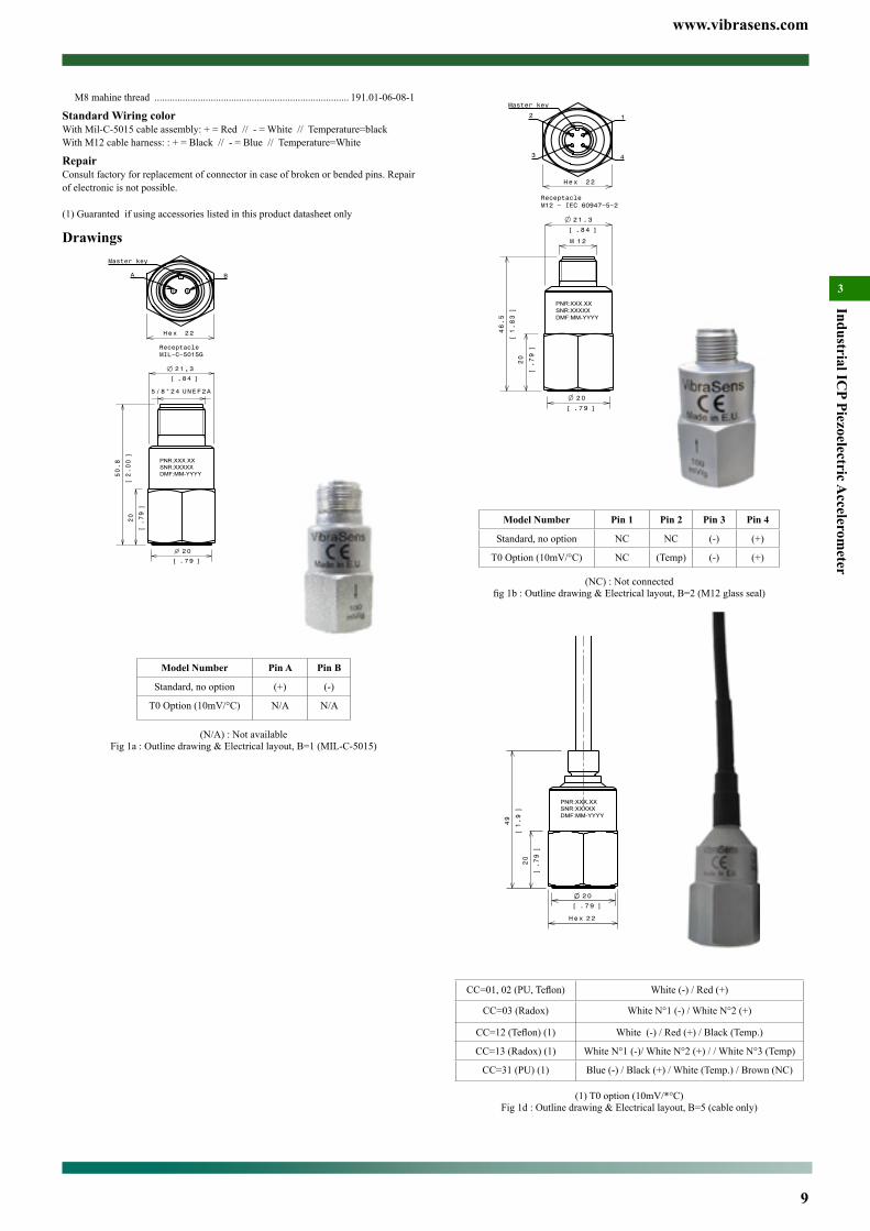
(NC) : Not connectedfig1b:Outlinedrawing&Electricallayout,B=2(M12glassseal)
20
.79[ ]
22Hex
20
.79
[]
49
1.9
[]
CC=01,02(PU,Teflon) White (-) / Red (+)
CC=03 (Radox) White N°1 (-) / White N°2 (+)
CC=12(Teflon)(1) White (-) / Red (+) / Black (Temp.)
CC=13 (Radox) (1) White N°1 (-)/ White N°2 (+) / / White N°3 (Temp)
CC=31 (PU) (1) Blue (-) / Black (+) / White (Temp.) / Brown (NC)
(1) T0 option (10mV/*°C)Fig 1d : Outline drawing & Electrical layout, B=5 (cable only)
M8 mahine thread ............................................................................ 191.01-06-08-1
Standard Wiring colorWith Mil-C-5015 cable assembly: + = Red // - = White // Temperature=blackWith M12 cable harness: : + = Black // - = Blue // Temperature=White
RepairConsult factory for replacement of connector in case of broken or bended pins. Repair of electronic is not possible.
(1) Guaranted if using accessories listed in this product datasheet only
Drawings
21,3
.84[ ]
20
.79
[]
2 0
.79[ ]
UNEF2A5/8"24
50.8
2.00
[]
ReceptacleMIL−C−5015G
22Hex
Master key
BA
Model Number Pin A Pin B
Standard, no option (+) (-)
T0 Option (10mV/°C) N/A N/A
(N/A) : Not availableFig 1a : Outline drawing & Electrical layout, B=1 (MIL-C-5015)
www.vibrasens.com
10
Indu
stri
al IC
P Pi
ezoe
lect
ric A
ccel
erom
eter
3
20
.79[ ]
22Hex
20
.79
[]
49
1.9
[]
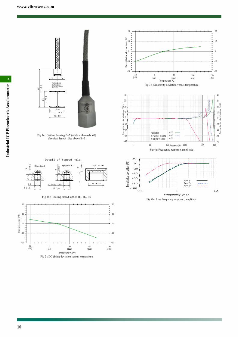
Fig 1e : Outline drawing B=7 (cable with overbraid)electrical layout : See above B=5
6M
6
.236
[]
7 ,5
.295[ ]
Standard
Detail of tapped hole
Option H7
6
.236
[]
7 ,5
.295[ ]
1/4"28 UNF
Option H1
7
.276
[]
1 6M x2
Fig 1h : Housing thread, option H1, H2, H7
0(32)
50(122)
100(212)
-20
-50(-58)
150(302)
-10
0
10
20
Bia
s d
evia
tion (
%)
Temperature °C (°F)
-20
-10
0
10
20
Fig 2 : DC (Bias) deviation versus temperature
0(32)
50(122)
100(212)
-20
-50(-58)
150(302)
-10
0
10
20
Temperature °C
-20
-10
0
10
20
Sensitiv
ity d
evia
tion (
%)
Fig 3 : Sensitivity deviation versus temperature
1 10 100 1000
-10
0
10
20
Sensitiv
ity d
evia
tion (
%) *
Frequency (Hz) 10k 50k
40
30
-20
-30
-40
* Deviationin (%) for f < 10kHzin (dB) for f>10kHz
-10
0
10
20
40
30
-20
-30
-40
A=3A=6A=9
Sensitiv
ity d
evia
tion (
dB)
Fig 4a: Frequency response, amplitude
Fig 4b : Low Frequency response, amplitude

www.vibrasens.com
11
Industrial ICP Piezoelectric A
ccelerometer
3
Ordering information model 109To order, specify model number, options, accessories and suffix :
109.01- AA - B - TT - MM - HH - YYAA : Sensitivity
3 : 10 mV/g ±5 % 3D : 10 mV/g ±10 %3V : 10 mV/g ±20 %
5 : 50 mV/g ±5 %5D : 50 mV/g ±10 %5V : 50 mV/g ±20 %.
6 : 100 mV/g ±5 % (medium frequency, general purpose)6D : 100 mV/g ±10 % (medium frequency, general purpose)6V : 100 mV/g ±20 % (medium frequency, general purpose)
Available suffix : N, negative polarityB : Connector
2 : M12 glass sealB(CC-DD) Integral cable
5 (CC-DD) : Integral cable7 (CC-DD) : Integral cable with sstl overbraid protection8 (CC-DD) : Integral cable with stainless steel protection conduit5, 7, 8 : epoxy seal.
CC : Cable Type02 : *Teflon FEP twisted pair Cable (200°C)
DD : length in metreTT : Temperature output.
omitted : no temperature outputT0 : 10 mV/°C. (range +2° to +120°C)
MM : Machine threadomitted : no mounting stud will be shipped with the sensor.M6 : M6x1M7 : 1/4” 28 UNF 2AM8 : M8x1.25
HH : Housing threadH2 : 10-32 UNF-2AH7 : 1/4” 28 UNF-2A
YY : Agency Approvalomitted : no agency approval
Special Engraving :Add ZXX at the end of the part number.XX is a number supplied by VibraSens
®ICP Accelerometer Model 109 Compact, Top connectorMain Characteristics• Annular shear mode• 20 kHz Bandwith• 10, 50, 100 mV/g• -55°C to 120 °C (-67°F to 250°F)• Dual case isolation with Faraday shield• Submersible version (150 metres) with associated IP68 over-
molded cable• life time hermetic sealing warranty (M12/Mil glass seal con-
nector)
Competitive advantage• Compare to obsolete compression design, annular shear
piezoelectric sensors feature better frequency response, improved base strain, lower noise, smaller size, ther-mal transient imunity and insensitivity to cable motion. Annular shear mode is also less susceptible to transverse vi-brations and better immune to electronic saturation at high fre-quency.
• Exceptional bias stability at elevated temperatures. (improved dynamic range, ex 80g dynamic for 100 mV/g sensitivity)
• Resistant to shock (magnet mounting) thanks to protected Mos-fet transistor input.
• ESD and reverse wiring protection.• The glass seal hermetic connector protects the piezoelectric discandtheelectronicfromharmfulenvironmentalinfluences,significantlyincreasingtheirreliabilityandlifetime.Associatedwith low cost IP68 overmolded M12 cable assembly it is a per-fect solution for submersible application down to 150 metres. Sensors with epoxy seal will always leak after few temperature cycles.
• M12 connector offers compatibility with numerous sensors used in automation. M12 overmolded cable assemblies are available from many cable manufacturers around the world. Mil cordset are expensive because they are only available from vibration sensor manufacturer.
DescriptionThe hermetic sealed industrial piezoelectric accelerometer model 109 is design to monitor the vibration in harsh industrial environment. It uses the industry standard ©ICP / ©IEPE / ©LIVM 2-wire voltage transmission technique with a 4 mA standard constant current supply. Signal ground is isolated from the mounting surface and outer case to prevent ground loops. Faraday shielding will limit sensitivity to EMC to a minimum. Annular shear mode design will prevent from thermal transient and from spurious signal from high transverse vi-brations. Low noise electronic and a temperature compensated design will give you accurate result over the complete temperature range. Large choice of frequency range will help to fit almost every cus-tomer requirements.
Typical applicationsVibrations measurement in the rugged environments of industrial ma-chinery monitoring. High frequency version (10mV/g) monitor the vibration on roller bearing, pumps cavitation, .... Medium frequency (100 mV/g) version monitor overall vibration on pumps, motors, fans, ...
Model 109.01 with overmolded IP 68 submersible angled M12 cable assembly
www.vibrasens.com
12
Indu
stri
al IC
P Pi
ezoe
lect
ric A
ccel
erom
eter
3
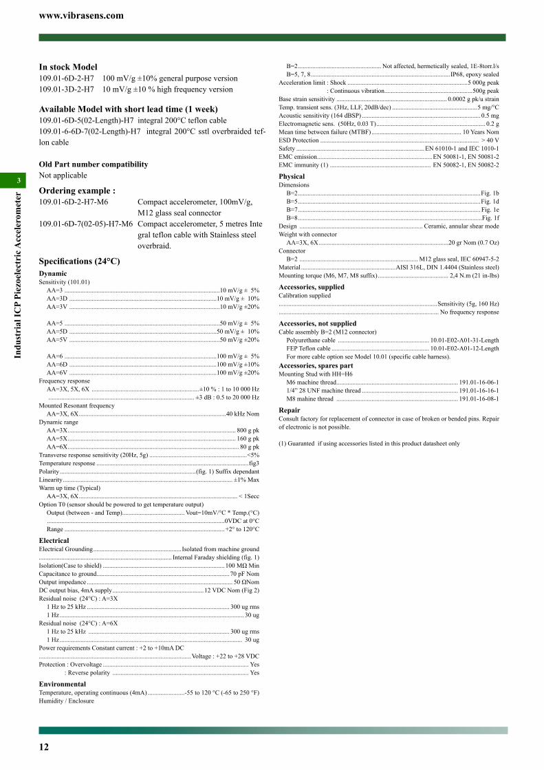
In stock Model109.01-6D-2-H7 100 mV/g ±10% general purpose version109.01-3D-2-H7 10 mV/g ±10 % high frequency version
Available Model with short lead time (1 week)109.01-6D-5(02-Length)-H7 integral 200°C teflon cable109.01-6-6D-7(02-Length)-H7 integral 200°C sstl overbraided tef-lon cable
Old Part number compatibilityNot applicable
Ordering example : 109.01-6D-2-H7-M6 Compact accelerometer, 100mV/g, M12 glass seal connector109.01-6D-7(02-05)-H7-M6 Compact accelerometer, 5 metres Inte gral teflon cable with Stainless steel overbraid.
Specifications (24°C)DynamicSensitivity (101.01)
AA=3 .................................................................................................10 mV/g ± 5%AA=3D ............................................................................................10 mV/g ± 10%AA=3V ..............................................................................................10 mV/g ±20%
AA=5 .................................................................................................50 mV/g ± 5%AA=5D ............................................................................................50 mV/g ± 10%AA=5V ..............................................................................................50 mV/g ±20%
AA=6 ...............................................................................................100 mV/g ± 5%AA=6D ............................................................................................100 mV/g ±10%AA=6V ............................................................................................100 mV/g ±20%
Frequency response AA=3X, 5X, 6X ...................................................................±10 % : 1 to 10 000 Hz ........................................................................................... ±3 dB : 0.5 to 20 000 Hz
Mounted Resonant frequencyAA=3X, 6X ............................................................................................40 kHz Nom
Dynamic rangeAA=3X ......................................................................................................... 800 g pkAA=5X ......................................................................................................... 160 g pkAA=6X ........................................................................................................... 80 g pk
Transverse response sensitivity (20Hz, 5g) .............................................................<5%Temperature response ...............................................................................................fig3Polarity .....................................................................................(fig. 1) Suffix dependantLinearity .......................................................................................................... ±1% MaxWarm up time (Typical)
AA=3X, 6X ................................................................................................... < 1SeccOption T0 (sensor should be powered to get temperature output)
Output (between - and Temp)....................................... Vout=10mV/°C * Temp.(°C) ...............................................................................................................0VDC at 0°CRange ....................................................................................................+2° to 120°C
ElectricalElectrical Grounding ....................................................... Isolated from machine ground................................................................................... Internal Faraday shielding (fig. 1)Isolation(Case to shield) ............................................................................100MΩMinCapacitance to ground ................................................................................... 70 pF NomOutput impedance ........................................................................................... 50ΩNomDC output bias, 4mA supply .........................................................12 VDC Nom (Fig 2)Residual noise (24°C) : A=3X
1 Hz to 25 kHz ......................................................................................... 300 ug rms1 Hz ................................................................................................................... 30 ug
Residual noise (24°C) : A=6X1 Hz to 25 kHz ........................................................................................ 300 ug rms1 Hz .................................................................................................................. 30 ug
Power requirements Constant current : +2 to +10mA DC...............................................................................................Voltage : +22 to +28 VDCProtection : Overvoltage ........................................................................................... Yes : Reverse polarity ..................................................................................... Yes
EnvironmentalTemperature, operating continuous (4mA) .......................-55 to 120 °C (-65 to 250 °F)Humidity / Enclosure
B=2 .................................................... Not affected, hermetically sealed, 1E-8torr.l/s B=5, 7, 8 ....................................................................................... IP68, epoxy sealed
Acceleration limit : Shock ...........................................................................5 000g peak : Continuous vibration.......................................................500g peakBase strain sensitivity ..................................................................... 0.0002 g pk/u strainTemp. transient sens. (3Hz, LLF, 20dB/dec) .....................................................5 mg/°C Acoustic sensitivity (164 dBSP) .......................................................................... 0.5 mg Electromagnetic sens. (50Hz, 0.03 T) .................................................................... 0.2 gMean time between failure (MTBF) ........................................................ 10 Years NomESD Protection ................................................................................................... > 40 VSafety ................................................................................EN 61010-1 and IEC 1010-1EMC emission ........................................................................EN 50081-1, EN 50081-2EMC immunity (1) ............................................................... EN 50082-1, EN 50082-2
PhysicalDimensions
B=2 ..................................................................................................................Fig. 1bB=5 ..................................................................................................................Fig. 1dB=7 .................................................................................................................. Fig. 1eB=8 ...................................................................................................................Fig. 1f
Design ............................................................................. Ceramic, annular shear modeWeight with connector
AA=3X, 6X .................................................................................20 gr Nom (0.7 Oz)Connector
B=2 .......................................................................... M12 glass seal, IEC 60947-5-2Material ...........................................................AISI 316L, DIN 1.4404 (Stainless steel)Mounting torque (M6, M7, M8 suffix) ............................................ 2,4 N.m (21 in-lbs)
Accessories, suppliedCalibration supplied...................................................................................................Sensitivity (5g, 160 Hz).................................................................................................... No frequency response
Accessories, not suppliedCable assembly B=2 (M12 connector)
Polyurethane cable ......................................................... 10.01-E02-A01-31-LengthFEP Teflon cable ............................................................. 10.01-E02-A01-12-LengthFor more cable option see Model 10.01 (specific cable harness).
Accessories, spares partMounting Stud with HH=H6
M6 machine thread ............................................................................ 191.01-16-06-11/4” 28 UNF machine thread ............................................................ 191.01-16-16-1M8 mahine thread ............................................................................ 191.01-16-08-1
RepairConsult factory for replacement of connector in case of broken or bended pins. Repair of electronic is not possible.
(1) Guaranted if using accessories listed in this product datasheet only
www.vibrasens.com
13
Industrial ICP Piezoelectric A
ccelerometer
3
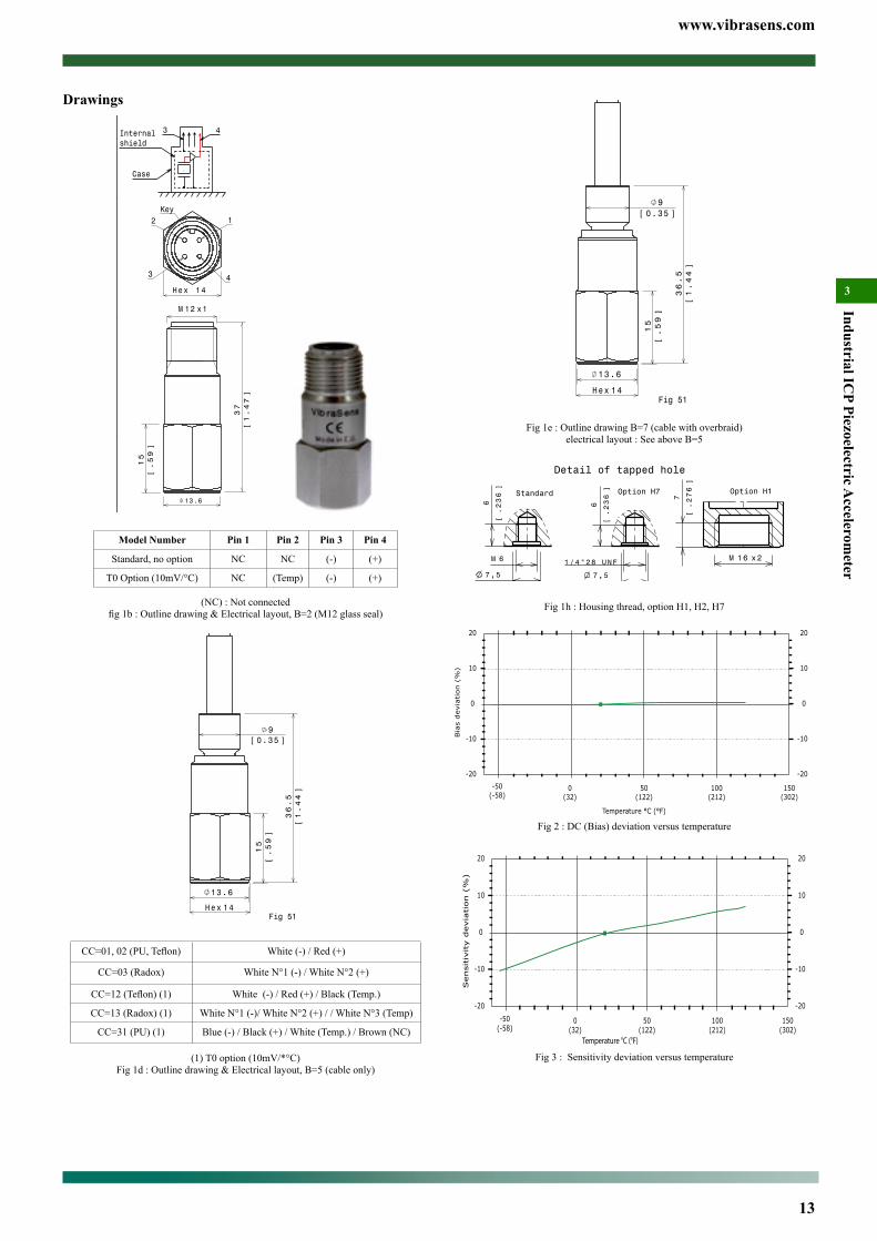
14Hex
36.5
1.44
[]
15
.59
[]
9[ ]0.35
13.6
Fig 51
Fig 1e : Outline drawing B=7 (cable with overbraid)electrical layout : See above B=5
6M
6
.236
[]
7 ,5
.295[ ]
Standard
Detail of tapped hole
Option H7
6
.236
[]
7 ,5
.295[ ]
1/4"28 UNF
Option H1
7
.276
[]
1 6M x2
Fig 1h : Housing thread, option H1, H2, H7
0(32)
50(122)
100(212)
-20
-50(-58)
150(302)
-10
0
10
20
Bia
s devia
tion (
%)
Temperature °C (°F)
-20
-10
0
10
20
Fig 2 : DC (Bias) deviation versus temperature
0(32)
50(122)
100(212)
-20
-50(-58)
150(302)
-10
0
10
20
Sensitiv
ity d
evia
tion (
%)
-20
-10
0
10
20
Temperature °C (°F)
Fig 3 : Sensitivity deviation versus temperature
Drawings
12M x1
37
1.47
[]
15
.59
[]
1 3.6
Key12
3 4
14Hex
Internalshield
Case −+
3 4
Model Number Pin 1 Pin 2 Pin 3 Pin 4
Standard, no option NC NC (-) (+)
T0 Option (10mV/°C) NC (Temp) (-) (+)
(NC) : Not connectedfig1b:Outlinedrawing&Electricallayout,B=2(M12glassseal)
14Hex
36.5
1.44
[]
15
.59
[]
9[ ]0.35
13.6
Fig 51
CC=01,02(PU,Teflon) White (-) / Red (+)
CC=03 (Radox) White N°1 (-) / White N°2 (+)
CC=12(Teflon)(1) White (-) / Red (+) / Black (Temp.)
CC=13 (Radox) (1) White N°1 (-)/ White N°2 (+) / / White N°3 (Temp)
CC=31 (PU) (1) Blue (-) / Black (+) / White (Temp.) / Brown (NC)
(1) T0 option (10mV/*°C)Fig 1d : Outline drawing & Electrical layout, B=5 (cable only)
www.vibrasens.com
14
Indu
stri
al IC
P Pi
ezoe
lect
ric A
ccel
erom
eter
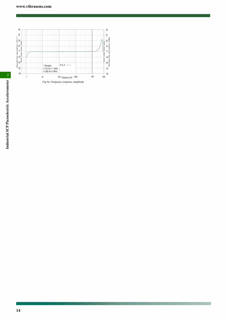
3 1 10 100 1000
-10
0
10
20
Sensitiv
ity d
evia
tio
n (
%) *
Frequency (Hz) 10k 50k
40
30
-20
-30
-40
* Deviationin (%) for f < 10kHzin (dB) for f>10kHz
-10
0
10
20
40
30
-20
-30
-40
A=3, 6
Sensitiv
ity d
evia
tio
n (
dB)
Fig 4a: Frequency response, amplitude

www.vibrasens.com
15
Industrial ICP Piezoelectric A
ccelerometer
3
01 : *Polyurethane twisted pair cable (90°C)02 : *Teflon FEP twisted pair Cable (200°C)03 : Radox twisted pair cable (120°C, halogen free)12 : Teflon FEP twisted triple Cable (200°C). For TO option.13 : Radox twisted triple (120°C, halogen free). For TO option31 : *Polyurethane 4 conductors cable (90°C). For T0 option
DD : length in metre (only integral cable B=5, 7, 8)Options :Temperature output
T0 : 10 mV/°C. (+2° to +120°C)Not available with Mil-C-5015 connector
Special Agency ApprovalX1 : Atex approved (July 2009)
Accessories (Machine thread):M6 : M6x1 Bolt, captive, hex socketM7 : 1/4” 28 UNF 2A Bolt, captive, hex socket
Special Engraving :Add ZXX at the end of the part number.XX is a number supplied by VibraSensNote : * = prefered and stocked items
Ordering information Model 103.12 (150°C Version)To order, specify model number, options, accessories and suffix :
103.12- A - B - Options - AccessoriesA : Sensitivity (±5%)
6 : *100 mV/g (medium frequency, general purpose)Available suffix : N, negative polarity
B : Connector / Integral cable1 : *MIL-C-5015, glass seal
Options & Accessories : see model 103.02
Ordering information Model 103.22 (±10% sensitivity)To order, specify model number, options, accessories and suffix :
103.22- A - B (CC-DD) - Options - AccessoriesTo order, specify model number, options and suffix :
A : Sensitivity (±10%)3 : *10 mV/g (high frequency)6 : *100 mV/g (medium frequency, general purpose)Available suffix : N, negative polarity
B : Connector / Integral cablesee model 103.02
CC : Cable Type (only integral cable B=5, 7, 8)see model 103.02
DD : length in metre (only integral cable B=5, 7, 8)
* Most Popular model :103.02-6-2 / 103.02-9-2 / 103.02-3-2 / 103.02-6-2-T0 103.22-6-2
®ICP Accelerometer Model 103 Premium, Side connectorMain Characteristics• -55°C to 150 °C (-67°F to 302°F)• ®ICP transmission mode• Annular shear mode• Dual case isolation with Faraday shield• Low, medium and high frequency version• High temperature version• IP67 with associated cable (B=2 only)• Complies with API 670 requirements (A=6 only)
Competitive advantage• Annular shear mode is less susceptible to transverse vibrations
and better immune to electronic saturation at high frequency• Exceptional bias voltage stability at elevated temperatures.• Low cost IP67 overmolded M12 cable assembly• M12 overmolded cable assembly is available through local elec-
tronic distributor• M12 offers compatibility with sensors used in automation
DescriptionThe hermetic sealed industrial piezoelectric accelerometer model 103 is design to monitor the vibration in harsh industrial environment. It uses the industry standard ®ICP 2-wire voltage transmission tech-nique with a 4 mA minimum constant current supply. Signal ground is isolated from the mounting surface and outer case to prevent ground loops. Faraday shielding will limit sensitivity to ESD to a minimum. Annular shear mode design will prevent from thermal transient and from spurious signal from high transverse vibrations. Low noise elec-tronic and a temperature compensated design will give you accurate result over the complete temperature range. Large choice of frequen-cy range will help to fit almost every customer requirements. Low frequency accelerometers (A=9) incorporate a low-pass filter within the conditioning electronics. This filter attenuate the sensor mechani-cal resonance and the associated distortion and overload.
Typical applicationsVibrations measurement in the rugged environments of industrial machinery monitoring. High frequency version will monitor the vi-bration on roller bearing, pumps cavitation, .... Medium frequency version will monitor overall vibration on pumps, motors, fans, ... Low frequency model is used in the petrochemical, machine tool, and pa-per industries for monitoring of slow speed agitators, cooling towers, ....
Ordering information Model 103.51To order, specify model number, options, accessories and suffix :
103.51- A - B (CC-DD) - Options - AccessoriesTo order, specify model number, options and suffix :
A : Sensitivity (±5%)3 : *10 mV/g (high frequency)6 : *100 mV/g (medium frequency, general purpose)9 : *500 mV/g (low frequency)Available suffix : N, negative polarity
B : Connector / Integral cable1 : MIL-C-5015, glass seal2 : *M12 glass seal5 : Integral cable7 : Integral cable with stainless steel overbraid protection8 : Integral cable with stainless steel protection conduitOption 5, 7, 8 needs additional information :(CC-DD)Options 5, 7, 8 are not stocked. Leadtime : 2 to 4 weeks.
CC : Cable Type (only integral cable B=5, 7, 8)
Model 103.02-A-2 with Overmolded M12 cable assembly
www.vibrasens.com
16
Indu
stri
al IC
P Pi
ezoe
lect
ric A
ccel
erom
eter
3
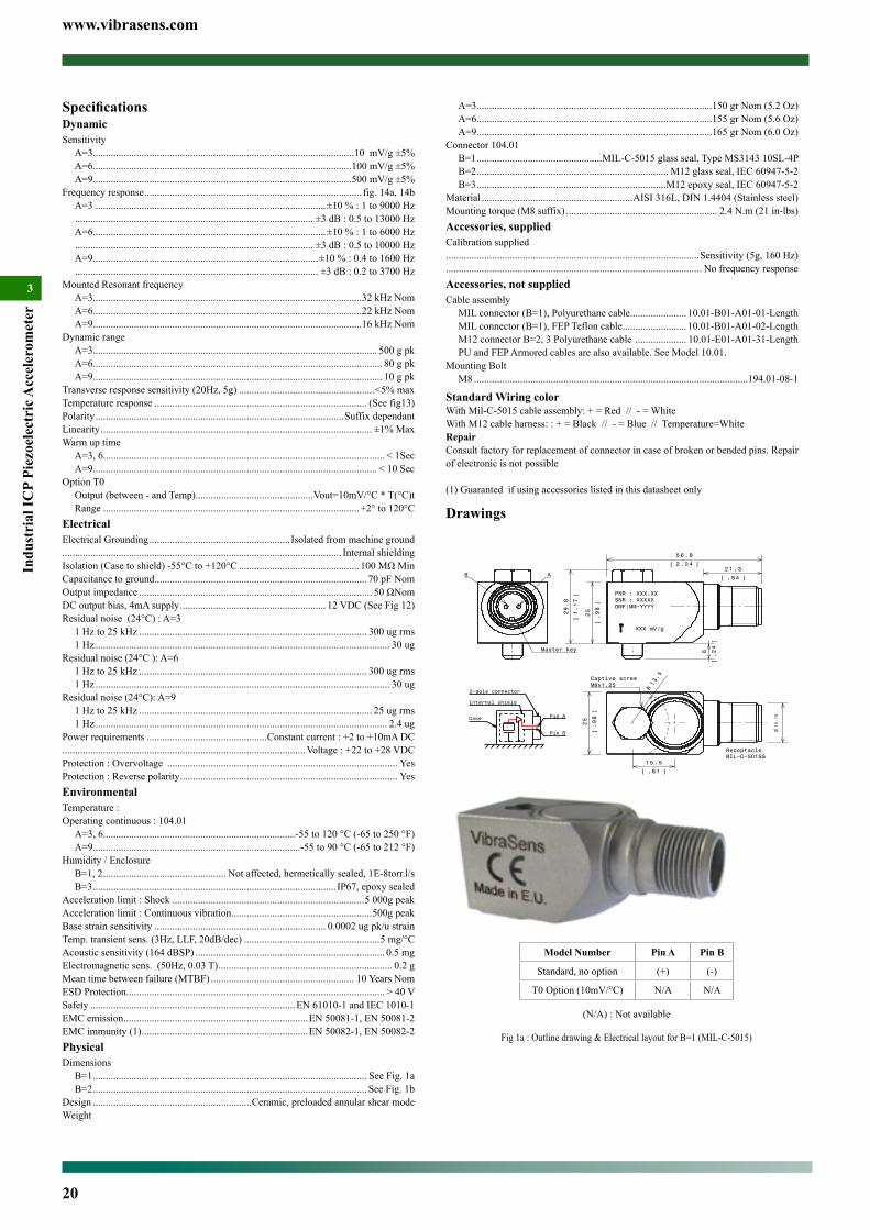
B=2 ........................................................................................................... See Fig. 1bDesign ..............................................................Ceramic, preloaded annular shear modeWeight
A=3............................................................................................150 gr Nom (5.2 Oz)A=6............................................................................................155 gr Nom (5.6 Oz)A=9............................................................................................165 gr Nom (6.0 Oz)
Connector B=1 .................................................MIL-C-5015 glass seal, Type MS3143 10SL-4PB=2 ........................................................................... M12 glass seal, IEC 60947-5-2
Material ...........................................................AISI 316L, DIN 1.4435 (Stainless steel)Mounting torque (M6, M7 suffix).................................................... 2.4 N.m (21 in-lbs)Accessories, suppliedCalibration supplied...................................................................................................Sensitivity (5g, 160 Hz).................................................................................................... No frequency responseAccessories, not suppliedCable assembly
MIL connector (B=1), Polyurethane cable ...................... 10.01-B01-A01-01-LengthMIL connector (B=1), FEP Teflon cable ......................... 10.01-B01-A01-02-LengthM12 connector B=2, 3 Polyurethane cable .................... 10.01-E01-A01-31-LengthPU and FEP Armored cables are also available. See Model 10.01.
Accessories, spares partMounting Stud
M6 machine thread ..................................................................................193.01-06-11/4” 28 UNF machine thread ..................................................................193.01-16-1
Standard Wiring colorWith Mil-C-5015 cable assembly: + = Red // - = WhiteWith M12 cable harness: : + = Black // - = Blue // Temperature=White
RepairConsult factory for replacement of connector in case of broken or bended pins. Repair of electronic is not possible
(1) Guaranted if using accessories listed in this datasheet only
Ordering example :103.02-6-2-M6 Premium Accelerometer, 100mV/g, M12 connector
SpecificationsDynamicSensitivity (103.02)
A=3 ......................................................................................................10 mV/g ±5%A=6 ....................................................................................................100 mV/g ±5%A=9 ....................................................................................................500 mV/g ±5%
Sensitivity (103.12)A=6 ....................................................................................................100 mV/g ±5%
Sensitivity (103.22)A=3 ....................................................................................................10 mV/g ±10%A=6 ..................................................................................................100 mV/g ±10%
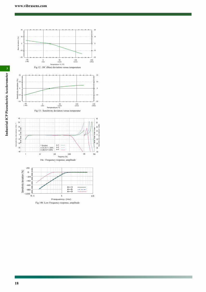
Frequency response (103.02 & 103.12) ...................................................... fig. 14a, 14bA=3 ..........................................................................................±10 % : 1 to 9000 Hz ............................................................................................. ±3 dB : 0.5 to 13000 HzA=6...........................................................................................±10 % : 1 to 6000 Hz ............................................................................................. ±3 dB : 0.5 to 10000 HzA=9,.......................................................................................±10 % : 0.4 to 1600 Hz ............................................................................................... ±3 dB : 0.2 to 3700 Hz
Mounted Resonant frequencyA=3.........................................................................................................32 kHz NomA=6.........................................................................................................22 kHz NomA=9.........................................................................................................16 kHz Nom
Dynamic rangeA=3............................................................................................................... 500 g pkA=6................................................................................................................. 80 g pkA=9................................................................................................................. 10 g pk
Transverse response sensitivity (20Hz, 5g) .....................................................<5% maxTemperature response ................................................................................... (See fig13)Polarity .................................................................................................Suffix dependantLinearity .......................................................................................................... ±1% MaxWarm up time (Typical)
A=3, 6.............................................................................................................. < 1SecA=9............................................................................................................... < 10 Sec
Option T0Output (between - and Temp)...............................................Vout=10mV/°C * T(°C)
z ......................................................................................................................... 30 ugResidual noise (24°C ): A=6
1 Hz to 25 kHz ......................................................................................... 300 ug rms1 Hz ................................................................................................................... 30 ug
Residual noise (24°C): A=91 Hz to 25 kHz ........................................................................................... 25 ug rms1 Hz .................................................................................................................. 2.4 ug
Power requirements ...............................................Constant current : +2 to +10mA DC...............................................................................................Voltage : +22 to +28 VDCProtection : Overvoltage .......................................................................................... YesProtection : Reverse polarity ..................................................................................... YesEnvironmentalTemperature :Operating continuous : 103.02 & 103.22 (max. current =4mA)
A=3, 6...........................................................................-55 to 120 °C (-65 to 250 °F)A=9.................................................................................-55 to 90 °C (-65 to 212 °F)
Operating continuous : 103.12 (max. current =4mA)B=1 ................................................................................-55 to 150°C (-65 to 302 °F)
Humidity / EnclosureB=1, 2 ................................................ Not affected, hermetically sealed, 1E-8torr.l/s
Acceleration limit : Shock ...........................................................................5 000g peakAcceleration limit : Continuous vibration .......................................................500g peakBase strain sensitivity ................................................................... 0.0002 ug pk/u strainTemp. transient sens. (3Hz, LLF, 20dB/dec) .....................................................5 mg/°C Acoustic sensitivity (164 dBSP) .......................................................................... 0.5 mg Electromagnetic sens. (50Hz, 0.03 T) .................................................................... 0.2 gMean time between failure (MTBF) ........................................................ 10 Years NomESD Protection ..................................................................................................... > 40 VSafety ................................................................................EN 61010-1 and IEC 1010-1EMC emission ........................................................................EN 50081-1, EN 50081-2EMC immunity (1) .................................................................EN 50082-1, EN 50082-2PhysicalDimensions
B=1 ........................................................................................................... See Fig. 1a
www.vibrasens.com
17
Industrial ICP Piezoelectric A
ccelerometer
3
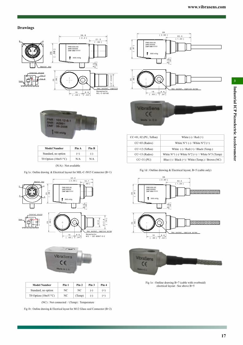
Hex socket, captive screw
8.6
.34[ ]
16
.63[ ]
25
.98
[]
25
.97
[]
6 6
2.60[ ]
6.5
.26
[]
3 0.5
1.20[ ]
CC=01,02(PU,Teflon) White (-) / Red (+)
CC=03 (Radox) White N°1 (-) / White N°2 (+)
CC=12(Teflon) White (-) / Red (+) / Black (Temp.)
CC=13 (Radox) White N°1 (-)/ White N°2 (+) / / White N°3 (Temp)
CC=31 (PU) Blue (-) / Black (+) / White (Temp.) / Brown (NC)
Fig 1d : Outline drawing & Electrical layout, B=5 (cable only)
25
.97
[]
6 6
2.60[ ]
6.5
.26
[]
3 0.5
1.20[ ]
Hex socket, captive screw
8.6
.34[ ]
16
.63[ ]
25
.98
[]
Fig 1e : Outline drawing B=7 (cable with overbraid)electrical layout : See above B=5
Drawings
25
.98
[]
6.5
.26
[]
5 6.9
2.2[ ]21.3
.84[ ]
17.8
.70
[]
25
.98
[]
8 .6
.34[ ]
5/8"−24UNEF
1 6
.63[ ]
Hex socket, captive screw
ReceptacleMIL−C−5015G
B A
Master key
Internal shield
Case −+
Pin A
Pin B
Model Number Pin A Pin B
Standard, no option (+) (-)
T0 Option (10mV/°C) N/A N/A
(N/A) : Not available
Fig 1a : Outline drawing & Electrical layout for MIL-C-5015 Connector (B=1)
−+
3
4
12
Internal shield
Case
25
.98
[]
12
M 17.8
.70
[]
1 6
.63[ ]
8.6
.34[ ]
Receptacle:M12 − IEC 60947−5−2
Hex socket, captive screw
6.5
.26
[]
25
.98
[]
5 2.3
2.06[ ] 16.7
.66[ ]
2 1
43
Master key
Model Number Pin 1 Pin 2 Pin 3 Pin 4
Standard, no option NC NC (-) (+)
T0 Option (10mV/°C) NC (Temp) (-) (+)
(NC) : Not connected / (Temp) : Temperature
Fig 1b : Outline drawing & Electrical layout for M12 Glass seal Connector (B=2)
www.vibrasens.com
18
Indu
stri
al IC
P Pi
ezoe
lect
ric A
ccel
erom
eter
3
0(32)
50(122)
100(212)
-20
-50(-58)
150(302)
-10
0
10
20
Bia
s devia
tion (
%)
Temperature °C (°F)
-20
-10
0
10
20
Fig 12 : DC (Bias) deviation versus temperature
0(32)
50(122)
100(212)
-20
-50(-58)
150(302)
-10
0
10
20
Temperature °C
-20
-10
0
10
20
Sen
sitivi
ty d
evia
tion
(%
)
Fig 13 : Sensitivity deviation versus temperatur
1 10 100 1000
-10
0
10
20
Sensitiv
ity d
evia
tion (
%)
*
Frequency (Hz)10k 50k
40
30
-20
-30
-40
* Deviationin (%) for f < 10kHzin (dB) for f>10kHz
-10
0
10
20
40
30
-20
-30
-40
A=3A=6A=9
Sensitiv
ity d
evia
tion (
dB)
14a : Frequency response, amplitude
Fig 14b :Low Frequency response, amplitude

www.vibrasens.com
19
Industrial ICP Piezoelectric A
ccelerometer
3M8 : M8x1.25 Hex Bolt, captiveSpecial Engraving :Add ZXX at the end of the part number.XX is a number supplied by VibraSens
Ordering example :104.01-6-2M8 Accelerometer, piezoelectric, 100mV/g, M12 glass seal connector
*Most Popular model :104.01-6-1 and 104.01-6-2
®ICP Accelerometer Model 104 Premium, Side connectorMain Characteristics• -55°C to 120 °C (-67°F to 250°F)• ®ICP transmission mode• Annular shear mode• Dual case isolation with Faraday shield• Low, medium and high frequency version• High temperature version• IP67 with associated cable (B=2 only)• Complies with API 670 requirements (A=6 only)
Competitive advantage• Annular shear mode is less susceptible to transverse vibrations
and better immune to electronic saturation at high frequency• Exceptional bias voltage stability at elevated temperatures.• Low cost IP67 overmolded M12 cable assembly• M12 overmolded cable assembly is available through local elec-
tronic distributor• M12 offers compatibility with sensors used in automation
DescriptionThe hermetic sealed industrial piezoelectric accelerometer model 104 is design to monitor the vibration in harsh industrial environment. It uses the industry standard ®ICP 2-wire voltage transmission tech-nique with a 4 mA minimum constant current supply. Signal ground is isolated from the mounting surface and outer case to prevent ground loops. Faraday shielding will limit sensitivity to ESD to a minimum. Annular shear mode design will prevent from thermal transient and from spurious signal from high transverse vibrations. Low noise elec-tronic and a temperature compensated design will give you accurate result over the complete temperature range. Large choice of frequen-cy range will help to fit almost every customer requirements. Low frequency accelerometers (A=9) incorporate a low-pass filter within the conditioning electronics. This filter attenuate the sensor mechani-cal resonance and the associated distortion and overload.
Typical applicationsVibrations measurement in the rugged environments of industrial machinery monitoring. High frequency version will monitor the vi-bration on roller bearing, pumps cavitation, .... Medium frequency version will monitor overall vibration on pumps, motors, fans, ... Low frequency model is used in the petrochemical, machine tool, and pa-per industries for monitoring of slow speed agitators, cooling towers, ....
Ordering information Model 104.01 (120°C version)To order, specify model number, options and suffix :104.01- A - B - Options - AccessoriesA : Sensitivity
3 : 10 mV/g (high frequency)6 : *100 mV/g (medium frequency, general purpose)9 : 500 mV/g (low frequency)Available suffix : N, negative polarity
B : Connector / Integral cable1 : *MIL-C-5015, glass seal2 : *M12 glass seal
Options :Temperature output
T0 : 10 mV/°C. (+2° to +120°C)Not available with Mil-C-5015 connector
Special Agency Approvalnone
Accessories
Model 104.01-A-2 with overmolded connector
www.vibrasens.com
20
Indu
stri
al IC
P Pi
ezoe
lect
ric A
ccel
erom
eter
3
A=3............................................................................................150 gr Nom (5.2 Oz)A=6............................................................................................155 gr Nom (5.6 Oz)A=9............................................................................................165 gr Nom (6.0 Oz)
Connector 104.01B=1 .................................................MIL-C-5015 glass seal, Type MS3143 10SL-4PB=2 ........................................................................... M12 glass seal, IEC 60947-5-2B=3 ..........................................................................M12 epoxy seal, IEC 60947-5-2
Material ...........................................................AISI 316L, DIN 1.4404 (Stainless steel)Mounting torque (M8 suffix) ........................................................... 2.4 N.m (21 in-lbs)Accessories, suppliedCalibration supplied...................................................................................................Sensitivity (5g, 160 Hz).................................................................................................... No frequency responseAccessories, not suppliedCable assembly
MIL connector (B=1), Polyurethane cable ...................... 10.01-B01-A01-01-LengthMIL connector (B=1), FEP Teflon cable ......................... 10.01-B01-A01-02-LengthM12 connector B=2, 3 Polyurethane cable .................... 10.01-E01-A01-31-LengthPU and FEP Armored cables are also available. See Model 10.01.
Mounting BoltM8 ...........................................................................................................194.01-08-1
Standard Wiring colorWith Mil-C-5015 cable assembly: + = Red // - = WhiteWith M12 cable harness: : + = Black // - = Blue // Temperature=WhiteRepairConsult factory for replacement of connector in case of broken or bended pins. Repair of electronic is not possible
(1) Guaranted if using accessories listed in this datasheet only
Drawings
ReceptacleMIL−C−5015G
Captive screwM8x1.25
15.76
R13.5
25
.98
[]
1 5.5
.61[ ]
PNR : XXX.XXSNR : XXXXXDMF:MM−YYYY
XXX mV/g
25
.98
[]
29.8
1.17
[]
2 1.3
.84[ ]
56.8
2.24[ ]
6
.24
[]
AB
Master key
Internal shield
2−pole connector
Case
−+
Pin A
Pin B
Model Number Pin A Pin B
Standard, no option (+) (-)
T0 Option (10mV/°C) N/A N/A
(N/A) : Not available
Fig 1a : Outline drawing & Electrical layout for B=1 (MIL-C-5015)
SpecificationsDynamicSensitivity
A=3......................................................................................................10 mV/g ±5%A=6.....................................................................................................100 mV/g ±5%A=9.....................................................................................................500 mV/g ±5%
Frequency response ..................................................................................... fig. 14a, 14bA=3 ..........................................................................................±10 % : 1 to 9000 Hz ............................................................................................. ±3 dB : 0.5 to 13000 HzA=6...........................................................................................±10 % : 1 to 6000 Hz ............................................................................................. ±3 dB : 0.5 to 10000 HzA=9........................................................................................±10 % : 0.4 to 1600 Hz ............................................................................................... ±3 dB : 0.2 to 3700 Hz
Mounted Resonant frequencyA=3.........................................................................................................32 kHz NomA=6.........................................................................................................22 kHz NomA=9.........................................................................................................16 kHz Nom
Dynamic rangeA=3............................................................................................................... 500 g pkA=6................................................................................................................. 80 g pkA=9................................................................................................................. 10 g pk
Transverse response sensitivity (20Hz, 5g) .....................................................<5% maxTemperature response ................................................................................... (See fig13)Polarity .................................................................................................Suffix dependantLinearity .......................................................................................................... ±1% MaxWarm up time
A=3, 6.............................................................................................................. < 1SecA=9............................................................................................................... < 10 Sec
Option T0Output (between - and Temp)..............................................Vout=10mV/°C * T(°C)tRange ....................................................................................................+2° to 120°C
ElectricalElectrical Grounding ....................................................... Isolated from machine ground............................................................................................................. Internal shieldingIsolation (Case to shield) -55°C to +120°C ...............................................100MΩMinCapacitance to ground ................................................................................... 70 pF NomOutput impedance ........................................................................................... 50ΩNomDC output bias, 4mA supply ......................................................... 12 VDC (See Fig 12)Residual noise (24°C) : A=3
1 Hz to 25 kHz ......................................................................................... 300 ug rms1 Hz ................................................................................................................... 30 ug
Residual noise (24°C ): A=61 Hz to 25 kHz ......................................................................................... 300 ug rms1 Hz ................................................................................................................... 30 ug
Residual noise (24°C): A=91 Hz to 25 kHz ........................................................................................... 25 ug rms1 Hz .................................................................................................................. 2.4 ug
Power requirements ...............................................Constant current : +2 to +10mA DC...............................................................................................Voltage : +22 to +28 VDCProtection : Overvoltage .......................................................................................... YesProtection : Reverse polarity ..................................................................................... YesEnvironmentalTemperature :Operating continuous : 104.01
A=3, 6...........................................................................-55 to 120 °C (-65 to 250 °F)A=9.................................................................................-55 to 90 °C (-65 to 212 °F)
Humidity / EnclosureB=1, 2 ................................................ Not affected, hermetically sealed, 1E-8torr.l/s B=3 ............................................................................................... IP67, epoxy sealed
Acceleration limit : Shock ...........................................................................5 000g peakAcceleration limit : Continuous vibration .......................................................500g peakBase strain sensitivity ................................................................... 0.0002 ug pk/u strainTemp. transient sens. (3Hz, LLF, 20dB/dec) .....................................................5 mg/°C Acoustic sensitivity (164 dBSP) .......................................................................... 0.5 mg Electromagnetic sens. (50Hz, 0.03 T) .................................................................... 0.2 gMean time between failure (MTBF) ........................................................ 10 Years NomESD Protection ..................................................................................................... > 40 VSafety ................................................................................EN 61010-1 and IEC 1010-1EMC emission ........................................................................EN 50081-1, EN 50081-2EMC immunity (1) .................................................................EN 50082-1, EN 50082-2PhysicalDimensions
B=1 ........................................................................................................... See Fig. 1aB=2 ........................................................................................................... See Fig. 1b
Design ..............................................................Ceramic, preloaded annular shear modeWeight
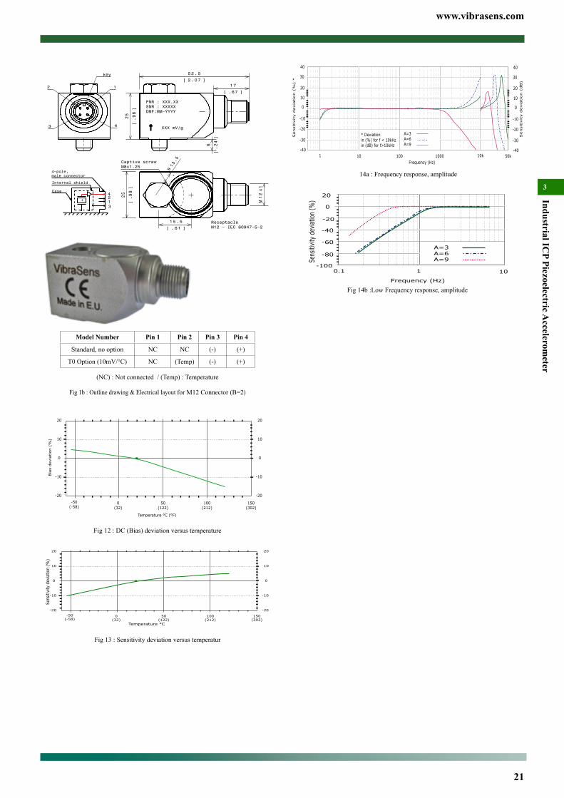
www.vibrasens.com
21
Industrial ICP Piezoelectric A
ccelerometer
3
1 10 100 1000
-10
0
10
20
Sensitiv
ity d
evia
tion (
%)
*
Frequency (Hz)10k 50k
40
30
-20
-30
-40
* Deviationin (%) for f < 10kHzin (dB) for f>10kHz
-10
0
10
20
40
30
-20
-30
-40
A=3A=6A=9
Sensitiv
ity d
evia
tion (
dB)
14a : Frequency response, amplitude
Fig 14b :Low Frequency response, amplitude
6
.24
[]
5 2.5
2.07[ ]17
.67[ ]
25
.98
[]
PNR : XXX.XXSNR : XXXXXDMF:MM−YYYY
XXX mV/g
12
Mx1
25
.98
[]
1 5.5
.61[ ]
13.5
R
ReceptacleM12 − IEC 60947−5−2
Captive screwM8x1.25
key
12
43
Internal shield
4−pole,male connector
Case
−+
3
421
Model Number Pin 1 Pin 2 Pin 3 Pin 4
Standard, no option NC NC (-) (+)
T0 Option (10mV/°C) NC (Temp) (-) (+)
(NC) : Not connected / (Temp) : Temperature
Fig 1b : Outline drawing & Electrical layout for M12 Connector (B=2)
0(32)
50(122)
100(212)
-20
-50(-58)
150(302)
-10
0
10
20
Bia
s devia
tion (
%)
Temperature °C (°F)
-20
-10
0
10
20
Fig 12 : DC (Bias) deviation versus temperature
0(32)
50(122)
100(212)
-20
-50(-58)
150(302)
-10
0
10
20
Temperature °C
-20
-10
0
10
20
Sens
itivi
ty d
evia
tion
(%)
Fig 13 : Sensitivity deviation versus temperatur
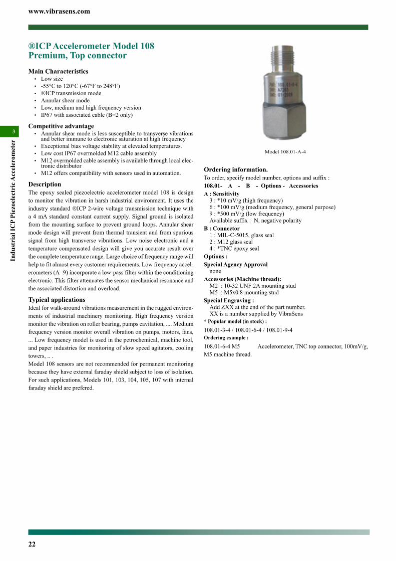
www.vibrasens.com
22
Indu
stri
al IC
P Pi
ezoe
lect
ric A
ccel
erom
eter
3
Ordering information.To order, specify model number, options and suffix :108.01- A - B - Options - AccessoriesA : Sensitivity
3 : *10 mV/g (high frequency)6 : *100 mV/g (medium frequency, general purpose)9 : *500 mV/g (low frequency)Available suffix : N, negative polarity
B : Connector1 : MIL-C-5015, glass seal2 : M12 glass seal4 : *TNC epoxy seal
Options :Special Agency Approval
noneAccessories (Machine thread):
M2 : 10-32 UNF 2A mounting studM5 : M5x0.8 mounting stud
Special Engraving :Add ZXX at the end of the part number.XX is a number supplied by VibraSens
* Popular model (in stock) :
108.01-3-4 / 108.01-6-4 / 108.01-9-4Ordering example :
108.01-6-4 M5 Accelerometer, TNC top connector, 100mV/g, M5 machine thread.
®ICP Accelerometer Model 108 Premium, Top connectorMain Characteristics• Low size• -55°C to 120°C (-67°F to 248°F)• ®ICP transmission mode• Annular shear mode• Low, medium and high frequency version• IP67 with associated cable (B=2 only)
Competitive advantage• Annular shear mode is less susceptible to transverse vibrations
and better immune to electronic saturation at high frequency• Exceptional bias voltage stability at elevated temperatures.• Low cost IP67 overmolded M12 cable assembly• M12 overmolded cable assembly is available through local elec-
tronic distributor• M12 offers compatibility with sensors used in automation.
DescriptionThe epoxy sealed piezoelectric accelerometer model 108 is design to monitor the vibration in harsh industrial environment. It uses the industry standard ®ICP 2-wire voltage transmission technique with a 4 mA standard constant current supply. Signal ground is isolated from the mounting surface to prevent ground loops. Annular shear mode design will prevent from thermal transient and from spurious signal from high transverse vibrations. Low noise electronic and a temperature compensated design will give you accurate result over the complete temperature range. Large choice of frequency range will help to fit almost every customer requirements. Low frequency accel-erometers (A=9) incorporate a low-pass filter within the conditioning electronic. This filter attenuates the sensor mechanical resonance and the associated distortion and overload.
Typical applicationsIdeal for walk-around vibrations measurement in the rugged environ-ments of industrial machinery monitoring. High frequency version monitor the vibration on roller bearing, pumps cavitation, .... Medium frequency version monitor overall vibration on pumps, motors, fans, ... Low frequency model is used in the petrochemical, machine tool, and paper industries for monitoring of slow speed agitators, cooling towers, .. .Model 108 sensors are not recommended for permanent monitoring because they have external faraday shield subject to loss of isolation. For such applications, Models 101, 103, 104, 105, 107 with internal faraday shield are prefered.
Model 108.01-A-4
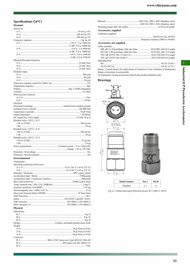
www.vibrasens.com
23
Industrial ICP Piezoelectric A
ccelerometer
3
Material ...........................................................AISI 316L, DIN 1.4435 (Stainless steel) ...................................................................... AISI 303, DIN 1.4301 (Stainless steel)
Mounting torque (M2, M5 suffix).................................................... 1.8 N.m (16 in-lbs)Accessories, suppliedCalibration supplied
..............................................................................................Sensitivity (5g, 160 Hz) ........................................................................ frequency response (20Hz to 10 kHz)
Accessories, not suppliedCable assembly
MIL (B=1), Polyurethane cable dia 5mm ....................... 10.01-B01-A01-01-LengthM12 (B=2 )Polyurethane cable dia 5mm ........................ 10.01-E01-A01-31-LengthTNC (B=4) PVC RG 174 dia 2.8 .....................................10.01-T02-F02-51-LengthTNC (B=4) PVC RG 58 dia 5 ..........................................10.01-T02-F02-52-Length
Mounting StudM5 ..................................................................................................... 191.01-15-05-110-32 UNF 2A ................................................................................... 191.01-15-15-1
Repair : Consult factory for replacement of connector in case of broken or bended pins. Repair of electronic is not possible(1) Guaranted if using accessories listed in this product datasheet only
Drawings
5/8"24UNEF2A
40.5
1.59
[]
1 7
.67[ ]
17.8
.70[ ]
ReceptacleMIL−C−5015G
A B
Master Key
19Hex
Case
−+
B A
Model Number Pin A Pin B
Standard (+) (-)
Fig 1a : Outline drawing & Electrical layout, B=1 (MIL-C-5015)
Specifications (24°C)DynamicSensitivity
A=3.......................................................................................................10 mV/g ±5%A=6.....................................................................................................100 mV/g ±5%A=9.....................................................................................................500 mV/g ±5%
Frequency response ......................................................................................... fig. 4a, 4bA=3 ........................................................................................±10 % : 1 to 11000 Hz ............................................................................................. ±3 dB : 0.5 to 16000 HzA=6...........................................................................................±10 % : 1 to 9000 Hz ............................................................................................. ±3 dB : 0.5 to 14000 HzA=9........................................................................................±10 % : 0.4 to 1600 Hz ............................................................................................... ±3 dB : 0.2 to 3700 Hz
Mounted Resonant frequencyA=3.........................................................................................................35 kHz NomA=6.........................................................................................................25 kHz NomA=9.........................................................................................................16 kHz Nom
Dynamic rangeA=3............................................................................................................... 500 g pkA=6................................................................................................................. 80 g pkA=9................................................................................................................. 10 g pk
Transverse response sensitivity (20Hz, 5g) .............................................................<5%Temperature response ...............................................................................................fig3Polarity .....................................................................................(fig. 1) Suffix dependantLinearity .......................................................................................................... ±1% MaxWarm up time (Typical)
A=3, 6.............................................................................................................. < 1SecA=9............................................................................................................... < 10 Sec
ElectricalElectrical Grounding ....................................................... Isolated from machine groundIsolation (Case to shield) ...........................................................................100MΩMinCapacitance to ground ................................................................................... 70 pF NomOutput impedance ........................................................................................... 50ΩNomDC output bias, 4mA supply ..................................................................12 VDC (Fig 2)Residual noise (24°C) : A=3
1 Hz to 25 kHz ......................................................................................... 300 ug rms1 Hz ................................................................................................................... 30 ug
Residual noise (24°C) : A=61 Hz to 25 kHz ......................................................................................... 300 ug rms1 Hz ................................................................................................................... 30 ug
Residual noise (24°C) : A=91 Hz to 25 kHz ........................................................................................... 25 ug rms1 Hz .................................................................................................................. 2.4 ug
Power requirements ...............................................Constant current : +2 to +10mA DC ..........................................................................................Voltage : +22 to +28 VDC
Protection : Overvoltage .......................................................................................... YesProtection : Reverse polarity ..................................................................................... YesEnvironmentalTemperature :Operating continuous (4mA max)
A=3, 6...........................................................................-55 to 120 °C (-65 to 252 °F)A=9.................................................................................-55 to 90 °C (-65 to 212 °F)
Humidity / Enclosure ........................................................................ IP67, epoxy sealedAcceleration limit : Shock ...........................................................................5 000g peakAcceleration limit : Continuous vibration .......................................................500g peakBase strain sensitivity ..................................................................... 0.0002 g pk/u strainTemp. transient sens. (3Hz, LLF, 20dB/dec) .....................................................5 mg/°C Acoustic sensitivity (164 dBSP) .......................................................................... 0.5 mg Electromagnetic sens. (50Hz, 0.03 T) .................................................................... 0.2 gMean time between failure (MTBF) ........................................................ 10 Years NomESD Protection ..................................................................................................... > 40 VSafety ................................................................................EN 61010-1 and IEC 1010-1EMC emission ........................................................................EN 50081-1, EN 50081-2EMC immunity (1) .................................................................EN 50082-1, EN 50082-2PhysicalDimensions
B=1 ................................................................................................................... Fig 1aB=2 ..................................................................................................................Fig. 1bB=4 ...................................................................................................................Fig 1d
Design ..............................................................Ceramic, preloaded annular shear modeWeight
A=3..............................................................................................34 gr Nom (2.8 Oz)A=6..............................................................................................39 gr Nom (3.0 Oz)A=9,.............................................................................................44 gr Nom (3.4 Oz)
ConnectorB=1 .................................................MIL-C-5015 glass seal, Type MS3143 10SL-4PB=2 ........................................................................... M12 glass seal, IEC 60947-5-2B=4 ..................................................................................................................... TNC
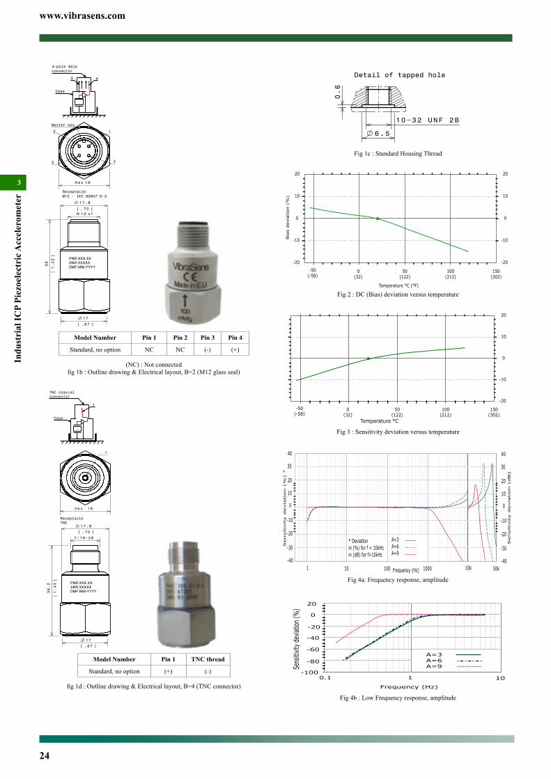
www.vibrasens.com
24
Indu
stri
al IC
P Pi
ezoe
lect
ric A
ccel
erom
eter
3
6.5
10−32 UNF 2B
0.6
Detail of tapped hole
Fig 1c : Standard Housing Thread
0(32)
50(122)
100(212)
-20
-50(-58)
150(302)
-10
0
10
20
Bia
s d
evia
tion (
%)
Temperature °C (°F)
-20
-10
0
10
20
Fig 2 : DC (Bias) deviation versus temperature
0(32)
50(122)
100(212)
-20
-50(-58)
150(302)
-10
0
10
20
Temperature °C
-20
-10
0
10
20
Sensi
tivity d
evia
tion (
%)
Fig 3 : Sensitivity deviation versus temperature
1 10 100 1000
-10
0
10
20
Sensitiv
ity d
evia
tion (
%) *
Frequency (Hz) 10k 50k
40
30
-20
-30
-40
* Deviationin (%) for f < 10kHzin (dB) for f>10kHz
-10
0
10
20
40
30
-20
-30
-40
A=3A=6A=9
Sensitiv
ity d
evia
tion (
dB)
Fig 4a: Frequency response, amplitude
Fig 4b : Low Frequency response, amplitude
Case
4−pole maleconnector
−+
3 4
36
1.42
[]
1 7.8
.70[ ]
17
.67[ ]
ReceptacleM12 − IEC 60947−5−2
12M x1
Master key
12
3 4
19Hex
Model Number Pin 1 Pin 2 Pin 3 Pin 4
Standard, no option NC NC (-) (+)
(NC) : Not connectedfig1b:Outlinedrawing&Electricallayout,B=2(M12glassseal)
17
.67[ ]
36.2
1.43
[]
7 /16−28
ReceptacleTNC
17.8
.70[ ]
1
19Hex
Case
−+
1
TNC coaxialconnector
Model Number Pin 1 TNC thread
Standard, no option (+) (-)
fig1d:Outlinedrawing&Electricallayout,B=4(TNCconnector)

www.vibrasens.com
25
Industrial ICP Piezoelectric A
ccelerometer
3
Options :Housing thread (Standard thread : M6x1)
H1 : M16x2 (quick mouting + 120° positioning) (Not stocked)H2 : Quick fit mounting (Not stocked)H7 : 1/4” 28 UNF-2A. (Not stocked)option H2 and H1 are recommended for integral cable.option H7 is available for North American market.
Temperature outputT0 : 10 mV/°C. (+2° to +120°C)Not available with Mil-C-5015 2 pins connector
Special Agency Approvalnone
Accessories (Machine thread):M6 : M6x1 mounting studM7 : 1/4” 28 UNF 2A mounting studM8 : M8x1.25 mounting studW6 : Swivel adaptor
Special Engraving :Add ZXX at the end of the part number.XX is a number supplied by VibraSens
* Most Popular model :111.01-6-2 / 111.01-6-1
Ordering example : 111.01-6-1M6 Piezovelocity sensor, MIL 5015 glass seal top con-nector
®ICP PiezoVelocity sensor Model 111 Top ConnectorMain Characteristics• 100 mV/ips or 4 mV/mm/s• -55°C to 120 °C (-67°F to 248°F)• ®ICP transmission mode• Annular shear mode• Dual case isolation with Faraday shield• IP67 with associated cable (B=2, 3 only)
Competitive advantage• Annular shear mode is less susceptible to base strain.• Ultra low noise electronic• Miswiring and surge protections• Low cost IP67 overmolded M12 cable assembly• M12 overmolded cable assembly is available through local elec-
tronic distributor• M12 offers compatibility with sensors used in automation.
DescriptionThe hermetic sealed industrial piezovelocity transducer model 111 is design to monitor the vibration in harsh industrial environment. It uses the industry standard ©ICP 2-wire voltage transmission tech-nique with a 4 mA standard constant current supply. Signal ground is isolated from the mounting surface and outer case to prevent ground loops. Faraday shielding will limit sensitivity to EMC to a minimum. Annular shear mode design will prevent from thermal transient and base strain. Low noise electronic and a temperature compensated design will give you accurate result over the complete temperature range.
Typical applicationsVelocity is the preferred measurement for most rotating machines with rolling element bearings. Unfortunately it is sometimes impos-sible to get velocity (with digital or analog integration) from standard piezoelectric accelerometer : very high frequency noise can overload the accelerometer and saturate the output. Piezovelocity sensors use an internal integration circuit which inherently decrease high fre-quency signals allowing better measurement of low frequency signal. Paper machine dryers (when steam leaks), pumps (cavitation high frequency noise) are prone to such phenomenom.
Ordering information model 111.01To order, specify model number, options and suffix :
111.01- A - B (CC-DD) - Options - AccessoriesA : Sensitivity (Suffix)
6 : 100 mV/ips (4mV/mm/s) Available suffix : N, negative polarity
B : Connector / Integral cable1 : *MIL-C-5015, glass seal2 : *M12 glass seal3 : M12 epoxy sealed5 : *Integral cable7 : *Integral cable with stainless steel overbraid protection8 : Integral cable with stainless steel protection conduitOption 5, 7, 8 needs additional information :(CC-DD)Options 3, 5, 7, 8 are not stocked. Leadtime : 2 to 4 weeks.CC : Cable Type (only integral cable B=5, 7, 8)01 : *Polyurethane twisted pair cable (90°C)02 : *Teflon FEP twisted pair Cable (200°C)03 : Radox twisted pair cable (120°C, halogen free)12 : Teflon FEP twisted triple Cable (200°C). For TO option.13 : Radox twisted triple (120°C, halogen free). For TO option31 : *Polyurethane 4 conductors cable (90°C). For T0 option
DD : length in metre (only integral cable B=5, 7, 8)
Model 111.01-A-2 with Overmolded M12 cable assembly
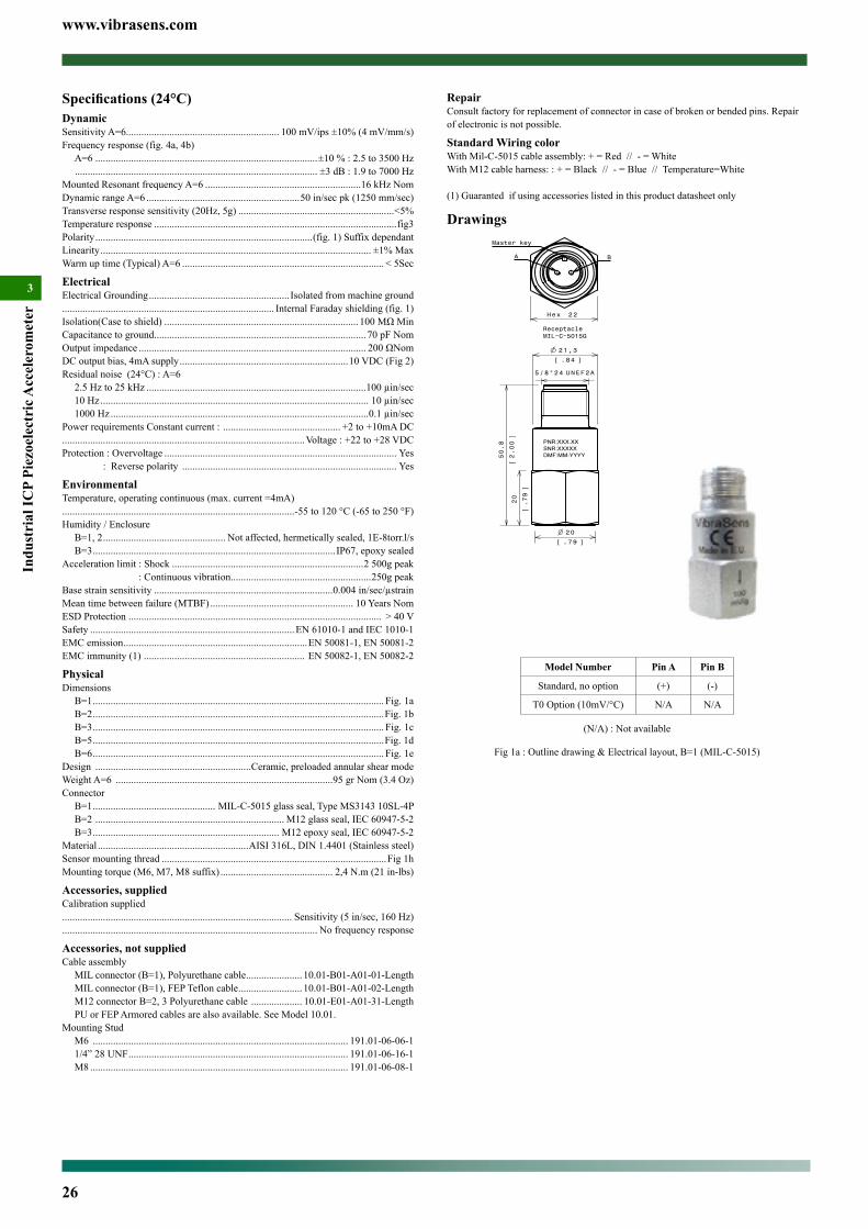
www.vibrasens.com
26
Indu
stri
al IC
P Pi
ezoe
lect
ric A
ccel
erom
eter
3
RepairConsult factory for replacement of connector in case of broken or bended pins. Repair of electronic is not possible.
Standard Wiring colorWith Mil-C-5015 cable assembly: + = Red // - = WhiteWith M12 cable harness: : + = Black // - = Blue // Temperature=White
(1) Guaranted if using accessories listed in this product datasheet only
Drawings
21,3
.84[ ]
20
.79
[]
2 0
.79[ ]
UNEF2A5/8"24
50.8
2.00
[]
ReceptacleMIL−C−5015G
22Hex
Master key
BA
Model Number Pin A Pin B
Standard, no option (+) (-)
T0 Option (10mV/°C) N/A N/A
(N/A) : Not available
Fig 1a : Outline drawing & Electrical layout, B=1 (MIL-C-5015)
Specifications (24°C)DynamicSensitivity A=6............................................................ 100 mV/ips ±10% (4 mV/mm/s)Frequency response (fig. 4a, 4b)
A=6 .......................................................................................±10 % : 2.5 to 3500 Hz ............................................................................................... ±3 dB : 1.9 to 7000 Hz
Mounted Resonant frequency A=6 .............................................................16 kHz NomDynamic range A=6 ............................................................50 in/sec pk (1250 mm/sec)Transverse response sensitivity (20Hz, 5g) .............................................................<5%Temperature response ...............................................................................................fig3Polarity .....................................................................................(fig. 1) Suffix dependantLinearity .......................................................................................................... ±1% MaxWarm up time (Typical) A=6 ............................................................................... < 5Sec
ElectricalElectrical Grounding ....................................................... Isolated from machine ground................................................................................... Internal Faraday shielding (fig. 1)Isolation(Case to shield) ............................................................................100MΩMinCapacitance to ground ................................................................................... 70 pF NomOutput impedance ......................................................................................... 200ΩNomDC output bias, 4mA supply ..................................................................10 VDC (Fig 2)Residual noise (24°C) : A=6
2.5 Hz to 25 kHz ......................................................................................100 µin/sec10 Hz ......................................................................................................... 10 µin/sec1000 Hz .....................................................................................................0.1 µin/sec
Power requirements Constant current : .............................................. +2 to +10mA DC...............................................................................................Voltage : +22 to +28 VDCProtection : Overvoltage ........................................................................................... Yes : Reverse polarity .................................................................................... Yes
EnvironmentalTemperature, operating continuous (max. current =4mA)...........................................................................................-55 to 120 °C (-65 to 250 °F)Humidity / Enclosure
B=1, 2 ................................................ Not affected, hermetically sealed, 1E-8torr.l/s B=3 ............................................................................................... IP67, epoxy sealed
Acceleration limit : Shock ...........................................................................2 500g peak : Continuous vibration.......................................................250g peakBase strain sensitivity ......................................................................0.004 in/sec/µstrainMean time between failure (MTBF) ........................................................ 10 Years NomESD Protection ................................................................................................... > 40 VSafety ................................................................................EN 61010-1 and IEC 1010-1EMC emission ........................................................................EN 50081-1, EN 50081-2EMC immunity (1) ............................................................... EN 50082-1, EN 50082-2
PhysicalDimensions
B=1 .................................................................................................................. Fig. 1aB=2 ..................................................................................................................Fig. 1bB=3 .................................................................................................................. Fig. 1cB=5 ..................................................................................................................Fig. 1dB=6 .................................................................................................................. Fig. 1e
Design .............................................................Ceramic, preloaded annular shear modeWeight A=6 .....................................................................................95 gr Nom (3.4 Oz)Connector
B=1 ................................................ MIL-C-5015 glass seal, Type MS3143 10SL-4PB=2 .......................................................................... M12 glass seal, IEC 60947-5-2B=3 ......................................................................... M12 epoxy seal, IEC 60947-5-2
Material ...........................................................AISI 316L, DIN 1.4401 (Stainless steel)Sensor mounting thread ........................................................................................Fig 1hMounting torque (M6, M7, M8 suffix) ............................................ 2,4 N.m (21 in-lbs)
Accessories, suppliedCalibration supplied.......................................................................................... Sensitivity (5 in/sec, 160 Hz).................................................................................................... No frequency response
Accessories, not suppliedCable assembly
MIL connector (B=1), Polyurethane cable ...................... 10.01-B01-A01-01-LengthMIL connector (B=1), FEP Teflon cable ......................... 10.01-B01-A01-02-LengthM12 connector B=2, 3 Polyurethane cable .................... 10.01-E01-A01-31-LengthPU or FEP Armored cables are also available. See Model 10.01.
Mounting StudM6 .................................................................................................... 191.01-06-06-11/4” 28 UNF ...................................................................................... 191.01-06-16-1M8 ..................................................................................................... 191.01-06-08-1
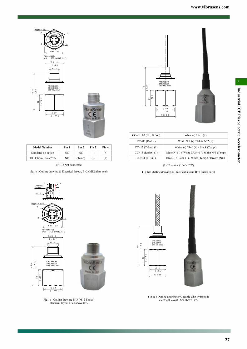
www.vibrasens.com
27
Industrial ICP Piezoelectric A
ccelerometer
3
20
.79[ ]
22Hex
20
.79
[]
49
1.9
[]
CC=01,02(PU,Teflon) White (-) / Red (+)
CC=03 (Radox) White N°1 (-) / White N°2 (+)
CC=12(Teflon)(1) White (-) / Red (+) / Black (Temp.)
CC=13 (Radox) (1) White N°1 (-)/ White N°2 (+) / / White N°3 (Temp)
CC=31 (PU) (1) Blue (-) / Black (+) / White (Temp.) / Brown (NC)
(1) T0 option (10mV/*°C)
Fig 1d : Outline drawing & Electrical layout, B=5 (cable only)
20
.79[ ]
22Hex
20
.79
[]
49
1.9
[]
Fig 1e : Outline drawing B=7 (cable with overbraid)electrical layout : See above B=5
22Hex
Master key
2 1
43
20
.79
[]
2 0
.79[ ]
46.5
1.83
[]
1 2M
ReceptacleM12 − IEC 60947−5−2
21.3
.84[ ]
Model Number Pin 1 Pin 2 Pin 3 Pin 4
Standard, no option NC NC (-) (+)
T0 Option (10mV/°C) NC (Temp) (-) (+)
(NC) : Not connected
fig1b:Outlinedrawing&Electricallayout,B=2(M12glassseal)
12M
21,3
.84[ ]
20
.79[ ]
48,4
1.91
[]
20
.79
[]
ReceptacleM12 − IEC 60947−5−2
22Hex
Master key
1
43
2
Internalshield
Case −+
3 4
Fig 1c : Outline drawing B=3 (M12 Epoxy)electrical layout : See above B=2
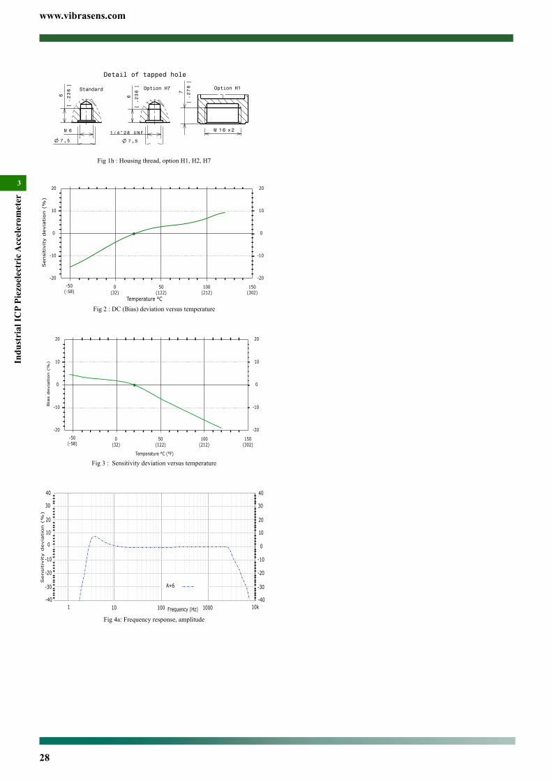
www.vibrasens.com
28
Indu
stri
al IC
P Pi
ezoe
lect
ric A
ccel
erom
eter
3
6M
6
.236
[]
7 ,5
.295[ ]
Standard
Detail of tapped hole
Option H7
6
.236
[]
7 ,5
.295[ ]
1/4"28 UNF
Option H1
7
.276
[]
1 6M x2
Fig 1h : Housing thread, option H1, H2, H7
0(32)
50(122)
100(212)
-20
-50(-58)
150(302)
-10
0
10
20
Sensi
tivity d
evia
tion (
%)
Temperature °C
-20
-10
0
10
20
Fig 2 : DC (Bias) deviation versus temperature
0(32)
50(122)
100(212)
-20
-50(-58)
150(302)
-10
0
10
20
Bia
s d
evia
tion (
%)
Temperature °C (°F)
-20
-10
0
10
20
Fig 3 : Sensitivity deviation versus temperature
1 10 100 1000
-10
0
10
20
Sensitiv
ity d
evia
tion (
%)
Frequency (Hz) 10k
40
30
-20
-30
-40
-10
0
10
20
40
30
-20
-30
-40
A=6
Fig 4a: Frequency response, amplitude

www.vibrasens.com
29
Industrial ICP Piezoelectric A
ccelerometer
3Options :Temperature output
T0 : 10 mV/°C. (+2° to +120°C)Not available with Mil-C-5015 connector
Special Agency ApprovalNone
Accessories (Machine thread):M6 : M6x1 Bolt, captive, hex socketM7 : 1/4” 28 UNF 2A Bolt, captive, hex socket
Special Engraving :Add ZXX at the end of the part number.XX is a number supplied by VibraSens
*Most Popular model (in stock) :113.02-6-2 / 113.02-6-1
Ordering example :113.02-6-2-M6 piezovelocity sensor, 100 mV/ips, M12 top connector
Specifications (24°C)DynamicSensitivity A=6............................................................ 100 mV/ips ±10% (4 mV/mm/s)Frequency response (fig. 4a, 4b)
A=6 .......................................................................................±10 % : 2.5 to 3500 Hz ............................................................................................... ±3 dB : 1.9 to 7000 Hz
Mounted Resonant frequency A=6 .............................................................16 kHz NomDynamic range A=6 ............................................................50 in/sec pk (1250 mm/sec)Transverse response sensitivity (20Hz, 5g) .............................................................<5%Temperature response ...............................................................................................fig3Polarity .....................................................................................(fig. 1) Suffix dependantLinearity .......................................................................................................... ±1% MaxWarm up time (Typical) A=6 ............................................................................... < 5Sec
ElectricalElectrical Grounding ....................................................... Isolated from machine ground................................................................................... Internal Faraday shielding (fig. 1)Isolation(Case to shield) ............................................................................100MΩMinCapacitance to ground ................................................................................... 70 pF NomOutput impedance ......................................................................................... 200ΩNomDC output bias, 4mA supply ..................................................................10 VDC (Fig 2)Residual noise (24°C) : A=6
2.5 Hz to 25 kHz ......................................................................................100 µin/sec10 Hz ......................................................................................................... 10 µin/sec1000 Hz .....................................................................................................0.1 µin/sec
Power requirements Constant current : .............................................. +2 to +10mA DC...............................................................................................Voltage : +22 to +28 VDCProtection : Overvoltage ........................................................................................... Yes : Reverse polarity .................................................................................... Yes
EnvironmentalTemperature, operating continuous (max. current =4mA)...........................................................................................-55 to 120 °C (-65 to 250 °F)Humidity / Enclosure
B=1, 2 ................................................ Not affected, hermetically sealed, 1E-8torr.l/s B=3 ............................................................................................... IP67, epoxy sealed
Acceleration limit : Shock ...........................................................................2 500g peak : Continuous vibration.......................................................250g peakBase strain sensitivity ......................................................................0.004 in/sec/µstrain
®ICP PiezoVelocity sensor Model 113 Side ConnectorMain Characteristics• 100 mV/ips or 4 mV/mm/s• -55°C to 120 °C (-67°F to 248°F)• ®ICP transmission mode• Annular shear mode• Dual case isolation with Faraday shield• IP67 with associated cable (B=2, 3 only)
Competitive advantage• Annular shear mode is less susceptible to base strain.• Ultra low noise electronic• Miswiring and surge protections• Low cost IP67 overmolded M12 cable assembly• M12 overmolded cable assembly is available through local elec-
tronic distributor• M12 offers compatibility with sensors used in automation.
DescriptionThe hermetic sealed industrial piezovelocity transducer model 113 is design to monitor the vibration in harsh industrial environment. It uses the industry standard ©ICP 2-wire voltage transmission tech-nique with a 4 mA standard constant current supply. Signal ground is isolated from the mounting surface and outer case to prevent ground loops. Faraday shielding will limit sensitivity to EMC to a minimum. Annular shear mode design will prevent from thermal transient and base strain. Low noise electronic and a temperature compensated design will give you accurate result over the complete temperature range.
Typical applicationsVelocity is the preferred measurement for most rotating machines with rolling element bearings. Unfortunately it is sometimes impos-sible to get velocity (with digital or analog integration) from standard piezoelectric accelerometer : very high frequency noise can overload the accelerometer and saturate the output. Piezovelocity sensors use an internal integration circuit which inherently decrease high fre-quency signals allowing better measurement of low frequency signal. Paper machine dryers (when steam leaks), pumps (cavitation high frequency noise) are prone to such phenomenom.
Ordering information model 113.01To order, specify model number, options and suffix :
113.01- A - B (CC-DD) - Options - AccessoriesA : Sensitivity (Suffix)
6 : 100 mV/ips (4mV/mm/s) Available suffix : N, negative polarity
B : Connector / Integral cable1 : *MIL-C-5015, glass seal2 : *M12 glass seal5 : *Integral cable7 : *Integral cable with stainless steel overbraid protection8 : Integral cable with stainless steel protection conduitOption 5, 7, 8 needs additional information :(CC-DD)Options 5, 7, 8 are not stocked. Leadtime : 2 to 4 weeks.
CC : Cable Type (only integral cable B=5, 7, 8)01 : *Polyurethane twisted pair cable (90°C)02 : *Teflon FEP twisted pair Cable (200°C)03 : Radox twisted pair cable (120°C, halogen free)12 : Teflon FEP twisted triple Cable (200°C). For TO option.13 : Radox twisted triple (120°C, halogen free). For TO option31 : *Polyurethane 4 conductors cable (90°C). For T0 option
DD : length in metre (only integral cable B=5, 7, 8)
Model 113.01-A-2 with Overmolded M12 cable assembly
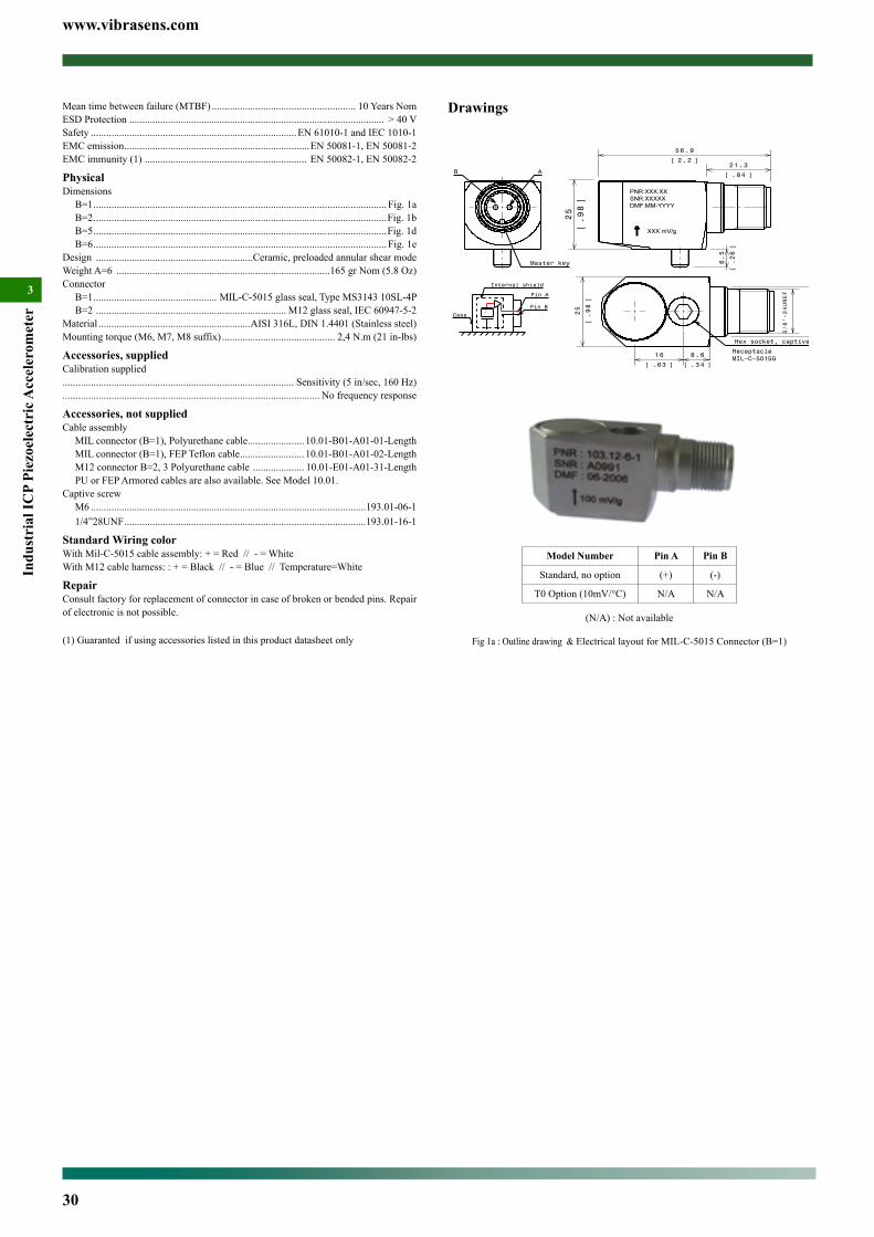
www.vibrasens.com
30
Indu
stri
al IC
P Pi
ezoe
lect
ric A
ccel
erom
eter
3
Drawings
25
.98
[]
6.5
.26
[]
5 6.9
2.2[ ]21.3
.84[ ]
17.8
.70
[]
25
.98
[]
8 .6
.34[ ]
5/8"−24UNEF
1 6
.63[ ]
Hex socket, captive screw
ReceptacleMIL−C−5015G
B A
Master key
Internal shield
Case −+
Pin A
Pin B
Model Number Pin A Pin B
Standard, no option (+) (-)
T0 Option (10mV/°C) N/A N/A
(N/A) : Not available
Fig 1a : Outline drawing & Electrical layout for MIL-C-5015 Connector (B=1)
Mean time between failure (MTBF) ........................................................ 10 Years NomESD Protection ................................................................................................... > 40 VSafety ................................................................................EN 61010-1 and IEC 1010-1EMC emission ........................................................................EN 50081-1, EN 50081-2EMC immunity (1) ............................................................... EN 50082-1, EN 50082-2
PhysicalDimensions
B=1 .................................................................................................................. Fig. 1aB=2 ..................................................................................................................Fig. 1bB=5 ..................................................................................................................Fig. 1dB=6 .................................................................................................................. Fig. 1e
Design .............................................................Ceramic, preloaded annular shear modeWeight A=6 ...................................................................................165 gr Nom (5.8 Oz)Connector
B=1 ................................................ MIL-C-5015 glass seal, Type MS3143 10SL-4PB=2 .......................................................................... M12 glass seal, IEC 60947-5-2
Material ...........................................................AISI 316L, DIN 1.4401 (Stainless steel)Mounting torque (M6, M7, M8 suffix) ............................................ 2,4 N.m (21 in-lbs)
Accessories, suppliedCalibration supplied.......................................................................................... Sensitivity (5 in/sec, 160 Hz).................................................................................................... No frequency response
Accessories, not suppliedCable assembly
MIL connector (B=1), Polyurethane cable ...................... 10.01-B01-A01-01-LengthMIL connector (B=1), FEP Teflon cable ......................... 10.01-B01-A01-02-LengthM12 connector B=2, 3 Polyurethane cable .................... 10.01-E01-A01-31-LengthPU or FEP Armored cables are also available. See Model 10.01.
Captive screwM6 ...........................................................................................................193.01-06-11/4”28UNF ..............................................................................................193.01-16-1
Standard Wiring colorWith Mil-C-5015 cable assembly: + = Red // - = WhiteWith M12 cable harness: : + = Black // - = Blue // Temperature=White
RepairConsult factory for replacement of connector in case of broken or bended pins. Repair of electronic is not possible.
(1) Guaranted if using accessories listed in this product datasheet only
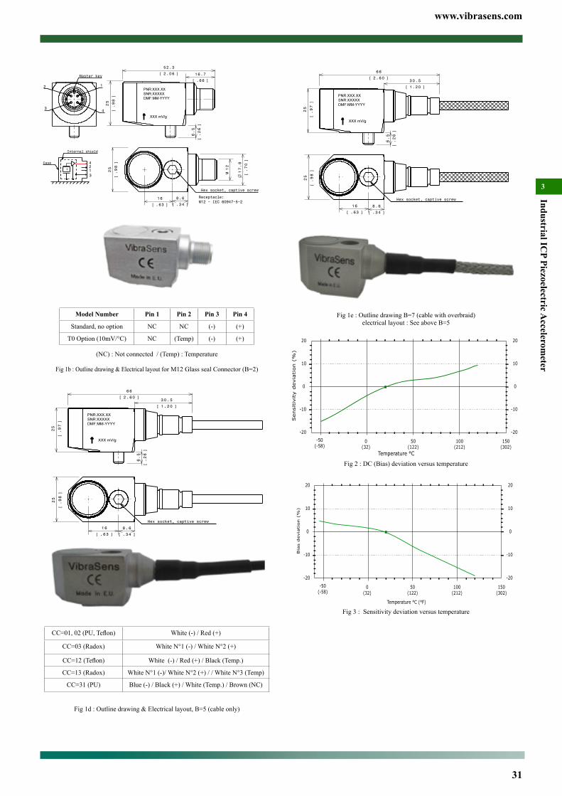
www.vibrasens.com
31
Industrial ICP Piezoelectric A
ccelerometer
3
25
.97
[]
6 6
2.60[ ]
6.5
.26
[]
3 0.5
1.20[ ]
Hex socket, captive screw
8.6
.34[ ]
16
.63[ ]
25
.98
[]
Fig 1e : Outline drawing B=7 (cable with overbraid)electrical layout : See above B=5
0(32)
50(122)
100(212)
-20
-50(-58)
150(302)
-10
0
10
20
Sensi
tivity d
evia
tion (
%)
Temperature °C
-20
-10
0
10
20
Fig 2 : DC (Bias) deviation versus temperature
0(32)
50(122)
100(212)
-20
-50(-58)
150(302)
-10
0
10
20
Bia
s d
evia
tion (
%)
Temperature °C (°F)
-20
-10
0
10
20
Fig 3 : Sensitivity deviation versus temperature
−+
3
4
12
Internal shield
Case
25
.98
[]
12
M 17.8
.70
[]
1 6
.63[ ]
8.6
.34[ ]
Receptacle:M12 − IEC 60947−5−2
Hex socket, captive screw6.5
.26
[]
25
.98
[]
5 2.3
2.06[ ] 16.7
.66[ ]
2 1
43
Master key
Model Number Pin 1 Pin 2 Pin 3 Pin 4
Standard, no option NC NC (-) (+)
T0 Option (10mV/°C) NC (Temp) (-) (+)
(NC) : Not connected / (Temp) : Temperature
Fig 1b : Outline drawing & Electrical layout for M12 Glass seal Connector (B=2)
Hex socket, captive screw
8.6
.34[ ]
16
.63[ ]
25
.98
[]
25
.97
[]
6 6
2.60[ ]
6.5
.26
[]
3 0.5
1.20[ ]
CC=01,02(PU,Teflon) White (-) / Red (+)
CC=03 (Radox) White N°1 (-) / White N°2 (+)
CC=12(Teflon) White (-) / Red (+) / Black (Temp.)
CC=13 (Radox) White N°1 (-)/ White N°2 (+) / / White N°3 (Temp)
CC=31 (PU) Blue (-) / Black (+) / White (Temp.) / Brown (NC)
Fig 1d : Outline drawing & Electrical layout, B=5 (cable only)
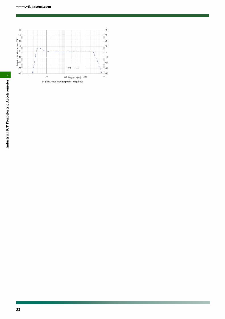
www.vibrasens.com
32
Indu
stri
al IC
P Pi
ezoe
lect
ric A
ccel
erom
eter
31 10 100 1000
-10
0
10
20
Sensitiv
ity d
evia
tion (
%)
Frequency (Hz) 10k
40
30
-20
-30
-40
-10
0
10
20
40
30
-20
-30
-40
A=6
Fig 4a: Frequency response, amplitude
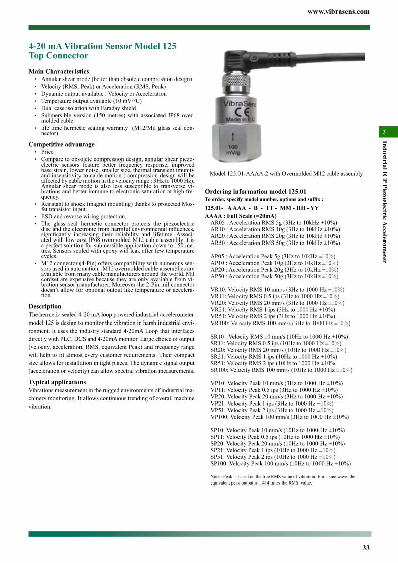
www.vibrasens.com
33
Industrial ICP Piezoelectric A
ccelerometer
3
Ordering information model 125.01To order, specify model number, options and suffix :
125.01- A AAA - B - TT - MM - HH - YYAAAA : Full Scale (=20mA)
AR05 : Acceleration RMS 5g (3Hz to 10kHz ±10%)AR10 : Acceleration RMS 10g (3Hz to 10kHz ±10%)AR20 : Acceleration RMS 20g (3Hz to 10kHz ±10%)AR50 : Acceleration RMS 50g (3Hz to 10kHz ±10%)
AP05 : Acceleration Peak 5g (3Hz to 10kHz ±10%)AP10 : Acceleration Peak 10g (3Hz to 10kHz ±10%)AP20 : Acceleration Peak 20g (3Hz to 10kHz ±10%)AP50 : Acceleration Peak 50g (3Hz to 10kHz ±10%)
VR10: Velocity RMS 10 mm/s (3Hz to 1000 Hz ±10%)VR11: Velocity RMS 0.5 ips (3Hz to 1000 Hz ±10%)VR20: Velocity RMS 20 mm/s (3Hz to 1000 Hz ±10%)VR21: Velocity RMS 1 ips (3Hz to 1000 Hz ±10%)VR51: Velocity RMS 2 ips (3Hz to 1000 Hz ±10%)VR100: Velocity RMS 100 mm/s (3Hz to 1000 Hz ±10%)
SR10 : Velocity RMS 10 mm/s (10Hz to 1000 Hz ±10%)SR11: Velocity RMS 0.5 ips (10Hz to 1000 Hz ±10%)SR20: Velocity RMS 20 mm/s (10Hz to 1000 Hz ±10%)SR21: Velocity RMS 1 ips (10Hz to 1000 Hz ±10%)SR51: Velocity RMS 2 ips (10Hz to 1000 Hz ±10%SR100: Velocity RMS 100 mm/s (10Hz to 1000 Hz ±10%)
VP10: Velocity Peak 10 mm/s (3Hz to 1000 Hz ±10%)VP11: Velocity Peak 0.5 ips (3Hz to 1000 Hz ±10%)VP20: Velocity Peak 20 mm/s (3Hz to 1000 Hz ±10%)VP21: Velocity Peak 1 ips (3Hz to 1000 Hz ±10%)VP51: Velocity Peak 2 ips (3Hz to 1000 Hz ±10%)VP100: Velocity Peak 100 mm/s (3Hz to 1000 Hz ±10%)
SP10: Velocity Peak 10 mm/s (10Hz to 1000 Hz ±10%)SP11: Velocity Peak 0.5 ips (10Hz to 1000 Hz ±10%)SP20: Velocity Peak 20 mm/s (10Hz to 1000 Hz ±10%)SP21: Velocity Peak 1 ips (10Hz to 1000 Hz ±10%)SP51: Velocity Peak 2 ips (10Hz to 1000 Hz ±10%)SP100: Velocity Peak 100 mm/s (10Hz to 1000 Hz ±10%)
Note : Peak is based on the true RMS value of vibration. For a sine wave, the equivalent peak output is 1.414 times the RMS. value.
4-20 mA Vibration Sensor Model 125 Top ConnectorMain Characteristics• Annular shear mode (better than obsolete compression design)• Velocity (RMS, Peak) or Acceleration (RMS, Peak)• Dynamic output available : Velocity or Acceleration• Temperature output available (10 mV/°C)• Dual case isolation with Faraday shield• Submersible version (150 metres) with associated IP68 over-
molded cable• life time hermetic sealing warranty (M12/Mil glass seal con-
nector)
Competitive advantage• Price• Compare to obsolete compression design, annular shear piezo-
electric sensors feature better frequency response, improved base strain, lower noise, smaller size, thermal transient imunity and insensitivity to cable motion ( compression design will be affected by cable motion in the velocity range : 3Hz to 1000 Hz). Annular shear mode is also less susceptible to transverse vi-brations and better immune to electronic saturation at high fre-quency.
• Resistant to shock (magnet mounting) thanks to protected Mos-fet transistor input.
• ESD and reverse wiring protection.• The glass seal hermetic connector protects the piezoelectric discandtheelectronicfromharmfulenvironmentalinfluences,significantly increasing their reliability and lifetime. Associ-ated with low cost IP68 overmolded M12 cable assembly it is a perfect solution for submersible application down to 150 me-tres. Sensors sealed with epoxy will leak after few temperature cycles.
• M12 connector (4-Pin) offers compatibility with numerous sen-sors used in automation. M12 overmolded cable assemblies are available from many cable manufacturers around the world. Mil cordset are expensive because they are only available from vi-bration sensor manufacturer. Moreover the 2-Pin mil connector doesn’t allow for optional outout like temperature or accelera-tion.
DescriptionThe hermetic sealed 4-20 mA loop powered industrial accelerometermodel 125 is design to monitor the vibration in harsh industrial envi-ronment. It uses the industry standard 4-20mA Loop that interfaces directly with PLC, DCS and 4-20mA monitor. Large choice of output (velocity, acceleration, RMS, equivalent Peak) and frequency range will help to fit almost every customer requirements. Their compact size allows for installation in tight places. The dynamic signal output (acceleration or velocity) can allow spectral vibration measurements.
Typical applicationsVibrations measurement in the rugged environments of industrial ma-chinery monitoring. It allows continuous trending of overall machine vibration.
Model 125.01-AAAA-2 with Overmolded M12 cable assembly
www.vibrasens.com
34
Indu
stri
al IC
P Pi
ezoe
lect
ric A
ccel
erom
eter
3
..................................................................................................... ±3 dB : 1 to 14000 HzOption : Dynamic velocity (DV)Sensitivity ..............................................................................100 mV/ips (4 mV/mm/s)Dynamic ................................................................................................................1.5 ipsPower .........Need 4-20 mA loop, no constant current source is needed, DC bias=2.6V. Frequency response ......................................................................±10 % : 3 to TBD Hz ........................................................................................................±3 dB : 1 to TBD Hz
ElectricalElectrical Grounding ....................................................... Isolated from machine ground................................................................................... Internal Faraday shielding (fig. 1)Isolation(Case to shield) ............................................................................100MΩMinCapacitance to ground ................................................................................... 70 pF NomMaximum Loop resistance ...................................... Rl Max=(Vdc power - 10V)/20mAMinimum Rl wattage .....................................................................Watt min=0.0004xRlPower requirements for two wire loop ..................................Voltage : +10 to +30 VDCProtection : Overvoltage ........................................................................................... Yes : Reverse polarity ..................................................................................... Yes
EnvironmentalTemperature, operating continuous max. loop curent =10mA ..................................................-55 to 120 °C (-65 to 250 °F)max. loop curent =20mA.....................................................-55 to 90 °C (-65 to 212 °F)Humidity / Enclosure
B=1, 2 .............................. Glass seal, Not affected, hermetically sealed, 1E-8torr.l/sB=5, 7, 8 .............................................................................................. Epoxy sealing
Acceleration limit : Shock ...........................................................................2 500g peak : Continuous vibration.......................................................250g peakMean time between failure (MTBF) .......................................................... 6 Years NomESD Protection ................................................................................................... > 40 VSafety ................................................................................EN 61010-1 and IEC 1010-1EMC emission ........................................................................EN 50081-1, EN 50081-2EMC immunity (1) ............................................................... EN 50082-1, EN 50082-2
PhysicalDimensions
B=1 .................................................................................................................. Fig. 1aB=2 ..................................................................................................................Fig. 1bB=5 ..................................................................................................................Fig. 1dB=7 ..................................................................................................................Fig. 1dB=8 ...................................................................................................................Fig. 1f
Design ......................................................................................... ceramic annular shear Weight .............................................................................................85 gr Nom (3.0 Oz)Connector
B=1 ................................................ MIL-C-5015 glass seal, Type MS3143 10SL-4PB=2 .......................................................................... M12 glass seal, IEC 60947-5-2
Material ...........................................................AISI 316L, DIN 1.4404 (Stainless steel)Housing thread ......................................................................................................Fig 1hMounting torque (M6, M7, M8 suffix) ............................................ 2,4 N.m (21 in-lbs)
Accessories, suppliedCalibration supplied........................................................................4-20mA Loop // DA or DV if applicable
Accessories, not suppliedCable assembly
MIL connector (B=1), Polyurethane cable ...................... 10.01-B22-A01-01-LengthMIL connector (B=1), FEP Teflon cable ......................... 10.01-B22-A01-02-LengthM12 connector (B=2) Polyurethane cable ..................... 10.01-E02-A01-31-LengthM12 connector (B=2), FEP Teflon cable ....................... 10.01-E02-A01-12-LengthPU or FEP Armored cables are also available. See Model 10.01.
Accessories, spares partMounting Stud with M6 Housing thread (HH=H6)
M6 .................................................................................................... 191.01-06-06-11/4” 28 UNF ...................................................................................... 191.01-06-16-1M8 ..................................................................................................... 191.01-06-08-1
RepairConsult factory for replacement of connector in case of broken or bended pins. Repair of electronic is not possible.
(1) Guaranted if using accessories listed in this product datasheet only
Wiring Schematic
B : Connector1 : MIL-C-5015, glass seal2 : M12 glass seal5 (CC-DD) : Integral cable7 (CC-DD) : Integral cable with sstl overbraid protection8 (CC-DD) : Integral cable with stainless steel protection conduitCC : Cable Type / DD : length in metre01 : *Polyurethane cable (90°C)02 : *Teflon FEP Cable (200°C)03 : Radox cable (120°C, halogen free)5, 7, 8 : epoxy seal
TT : Optional output (only one optional output is possible)Omitted : no optional outputT0: Temperature output10 mV/°C. (range +2° to +120°C)(Not available with Mil-C-5015 2-pin connector)DA: Acceleration Dynamic Output100 mV/g +-30% for VRXX, VPXX, AR05, AP0510mV/g +-30% for AR10, AR20, AR50, AP10, AP20, AP50.(not available with MIL-C-5015 2-pin connector)DV: Velocity Dynamic Output100 mV/ips +-30% for VRXX, VPXX, , ARXX, APXX(not available with MIL-C-5015 2-pin connector)
MM : Machine threadOmitted : no mounting stud will be shipped with the sensor.M6 : M6x1M7 : 1/4” 28 UNF 2AM8 : M8x1.25
HH : Housing threadOmitted or H6 : M6x1 (China, Europe, India, South America, ...)H1 : M16x2 (quick mounting + 120° positioning) (Not stocked)H2 : Quick fit mounting (Not stocked)H7 : 1/4” 28 UNF-2A. (U.S.A., UK, ...)
YY : Agency Approvalomitted : no agency approvalY1 : Atex approved (October 2010)
Special Engraving :Add ZXX at the end of the part number.XX is a number supplied by VibraSens
*Most Popular model (in stock) :125.01-VR20-2-DA // 125.01-VR21-2-DA
Ordering example : 125.01-VR20-2-DA-M6 4-20mA sensor, FS=20mm/s RMS, M12 top connector, Dynamic acceleration output
Specifications (24°C)DynamicSensitivity
No vibration ..............................................................................................4 mA ±5%Full scale ( see AAAA ordering information) ........................................20 mA ±5%Note : Equivalent Peak is based on the true RMS value of vibration. For a sine wave, the equivalent peak output is 1.414 times the RMS. value.
Frequency response ....................................................See AAAA ordering informationMounted Resonant frequency .....................................................................25 kHz NomTransverse response sensitivity (20Hz, 5g) .............................................................<5%Linearity .......................................................................................................... ±1% MaxTurn on time, 4-20 mA loop ............................................................................. < 10 SecOption : Temperature output (T0)
Output ........................................................................... Vout=10mV/°C * Temp.(°C) ...............................................................................................................0VDC at 0°CRange ....................................................................................................+2° to 120°CPower ..........................................................................................Need 4-20 mA loop
Option : Dynamic acceleration (DA)Sensitivity .................................................. See ordering information : 10 or 100 mV/gDynamic ................................................................................. 25 g for 100 mV/g output................................................................................................ 250 g for 10 mV/g outputPower .........Need 4-20 mA loop, no constant current source is needed, DC bias=2.6V. Frequency response ......................................................................±10 % : 3 to 9000 Hz
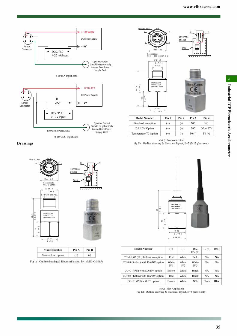
www.vibrasens.com
35
Industrial ICP Piezoelectric A
ccelerometer
3
22Hex
Master key
2 1
43
20
.79
[]
2 0
.79[ ]
46.5
1.83
[]
1 2M
ReceptacleM12 − IEC 60947−5−2
21.3
.84[ ]
Model Number Pin 1 Pin 2 Pin 3 Pin 4
Standard, no option (+) (-) NC NC
DA / DV Option (+) (-) NC DA or DV
Temperature T0 Option (+) (-) T0 (-) T0 (+)
(NC) : Not connectedfig1b:Outlinedrawing&Electricallayout,B=2(M12glassseal)
20
.79[ ]
22Hex
20
.79
[]
49
1.9
[]
Model Number (+) (-) DA, DV (+)
T0 (+) T0 (-)
CC=01,02(PU,Teflon),nooption Red White NA NA NA
CC=03 (Radox) with DA/DV option White N°1
White N°2
White N°3
NA NA
CC=01 (PU) with DA/DV option Brown White Black NA NA
CC=02(Teflon)withDA/DVoption Red White Black NA NA
CC=01 (PU) with T0 option Brown White N/A Black Blue
(NA) : Not ApplicableFig 1d : Outline drawing & Electrical layout, B=5 (cable only)
Internalshield
Case −+
2 1
DCS / PLC4-20 mA input
SensorConnector
+ 12 V to 30 V
- 0 V
DC Power Supply
-+
Dynamic Output (should be galvanically
isolated from PowerSupply Gnd)
4-20 mA Input card
SensorConnector
+ 12 V to 30 V
- 0 V
DC Power Supply
-+
R
I (mA)=U(mV)/R (Ohms)
DCS / PLC0-10 V input
Dynamic Output (should be galvanically
isolated from PowerSupply Gnd)
0-10 VDC Input card
Drawings
21,3
.84[ ]
20
.79
[]
2 0
.79[ ]
UNEF2A5/8"24
50.8
2.00
[]
ReceptacleMIL−C−5015G
22Hex
Master key
BA
Model Number Pin A Pin B
Standard, no option (+) (-)
Fig 1a : Outline drawing & Electrical layout, B=1 (MIL-C-5015)
Internalshield
Case −+
B A
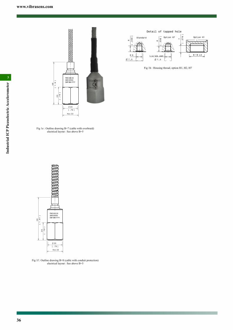
www.vibrasens.com
36
Indu
stri
al IC
P Pi
ezoe
lect
ric A
ccel
erom
eter
3
6M
6
.236
[]
7 ,5
.295[ ]
Standard
Detail of tapped hole
Option H7
6
.236
[]
7 ,5
.295[ ]
1/4"28 UNF
Option H1
7
.276
[]
1 6M x2
Fig 1h : Housing thread, option H1, H2, H7
20
.79[ ]
22Hex
20
.79
[]
49
1.9
[]
Fig 1e : Outline drawing B=7 (cable with overbraid)electrical layout : See above B=5
20
.79[ ]
22Hex
49
1.91
[]
20
.79
[]
Fig 1f : Outline drawing B=8 (cable with conduit protection)electrical layout : See above B=5
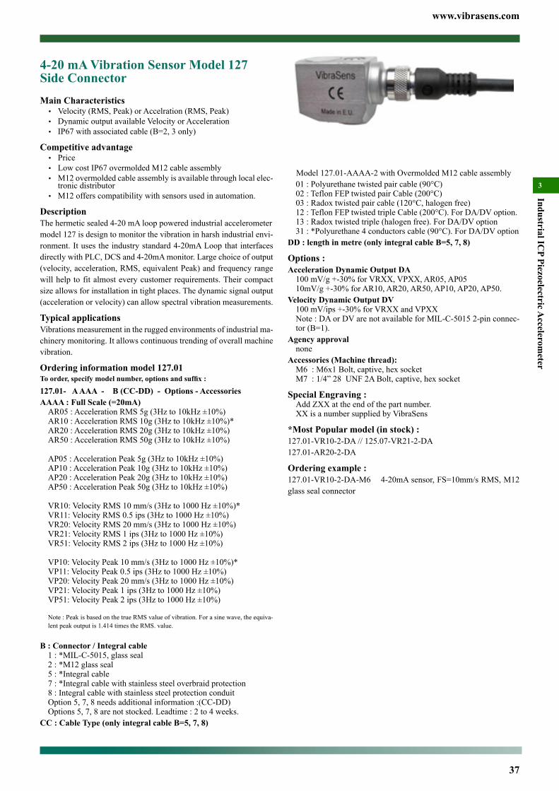
www.vibrasens.com
37
Industrial ICP Piezoelectric A
ccelerometer
301 : Polyurethane twisted pair cable (90°C)02 : Teflon FEP twisted pair Cable (200°C)03 : Radox twisted pair cable (120°C, halogen free)12 : Teflon FEP twisted triple Cable (200°C). For DA/DV option.13 : Radox twisted triple (halogen free). For DA/DV option31 : *Polyurethane 4 conductors cable (90°C). For DA/DV option
DD : length in metre (only integral cable B=5, 7, 8)
Options :Acceleration Dynamic Output DA
100 mV/g +-30% for VRXX, VPXX, AR05, AP0510mV/g +-30% for AR10, AR20, AR50, AP10, AP20, AP50.
Velocity Dynamic Output DV100 mV/ips +-30% for VRXX and VPXX Note : DA or DV are not available for MIL-C-5015 2-pin connec-tor (B=1).
Agency approvalnone
Accessories (Machine thread):M6 : M6x1 Bolt, captive, hex socketM7 : 1/4” 28 UNF 2A Bolt, captive, hex socket
Special Engraving :Add ZXX at the end of the part number.XX is a number supplied by VibraSens
*Most Popular model (in stock) :127.01-VR10-2-DA // 125.07-VR21-2-DA127.01-AR20-2-DA
Ordering example : 127.01-VR10-2-DA-M6 4-20mA sensor, FS=10mm/s RMS, M12 glass seal connector
4-20 mA Vibration Sensor Model 127 Side ConnectorMain Characteristics• Velocity (RMS, Peak) or Accelration (RMS, Peak)• Dynamic output available Velocity or Acceleration• IP67 with associated cable (B=2, 3 only)
Competitive advantage• Price• Low cost IP67 overmolded M12 cable assembly• M12 overmolded cable assembly is available through local elec-
tronic distributor• M12 offers compatibility with sensors used in automation.
DescriptionThe hermetic sealed 4-20 mA loop powered industrial accelerometermodel 127 is design to monitor the vibration in harsh industrial envi-ronment. It uses the industry standard 4-20mA Loop that interfaces directly with PLC, DCS and 4-20mA monitor. Large choice of output (velocity, acceleration, RMS, equivalent Peak) and frequency range will help to fit almost every customer requirements. Their compact size allows for installation in tight places. The dynamic signal output (acceleration or velocity) can allow spectral vibration measurements.
Typical applicationsVibrations measurement in the rugged environments of industrial ma-chinery monitoring. It allows continuous trending of overall machine vibration.
Ordering information model 127.01To order, specify model number, options and suffix :
127.01- A AAA - B (CC-DD) - Options - AccessoriesAAAA : Full Scale (=20mA)
AR05 : Acceleration RMS 5g (3Hz to 10kHz ±10%)AR10 : Acceleration RMS 10g (3Hz to 10kHz ±10%)*AR20 : Acceleration RMS 20g (3Hz to 10kHz ±10%)AR50 : Acceleration RMS 50g (3Hz to 10kHz ±10%)
AP05 : Acceleration Peak 5g (3Hz to 10kHz ±10%)AP10 : Acceleration Peak 10g (3Hz to 10kHz ±10%)AP20 : Acceleration Peak 20g (3Hz to 10kHz ±10%)AP50 : Acceleration Peak 50g (3Hz to 10kHz ±10%)
VR10: Velocity RMS 10 mm/s (3Hz to 1000 Hz ±10%)*VR11: Velocity RMS 0.5 ips (3Hz to 1000 Hz ±10%)VR20: Velocity RMS 20 mm/s (3Hz to 1000 Hz ±10%)VR21: Velocity RMS 1 ips (3Hz to 1000 Hz ±10%)VR51: Velocity RMS 2 ips (3Hz to 1000 Hz ±10%)
VP10: Velocity Peak 10 mm/s (3Hz to 1000 Hz ±10%)*VP11: Velocity Peak 0.5 ips (3Hz to 1000 Hz ±10%)VP20: Velocity Peak 20 mm/s (3Hz to 1000 Hz ±10%)VP21: Velocity Peak 1 ips (3Hz to 1000 Hz ±10%)VP51: Velocity Peak 2 ips (3Hz to 1000 Hz ±10%)
Note : Peak is based on the true RMS value of vibration. For a sine wave, the equiva-lent peak output is 1.414 times the RMS. value.
B : Connector / Integral cable1 : *MIL-C-5015, glass seal2 : *M12 glass seal5 : *Integral cable7 : *Integral cable with stainless steel overbraid protection8 : Integral cable with stainless steel protection conduitOption 5, 7, 8 needs additional information :(CC-DD)Options 5, 7, 8 are not stocked. Leadtime : 2 to 4 weeks.
CC : Cable Type (only integral cable B=5, 7, 8)
Model 127.01-AAAA-2 with Overmolded M12 cable assembly
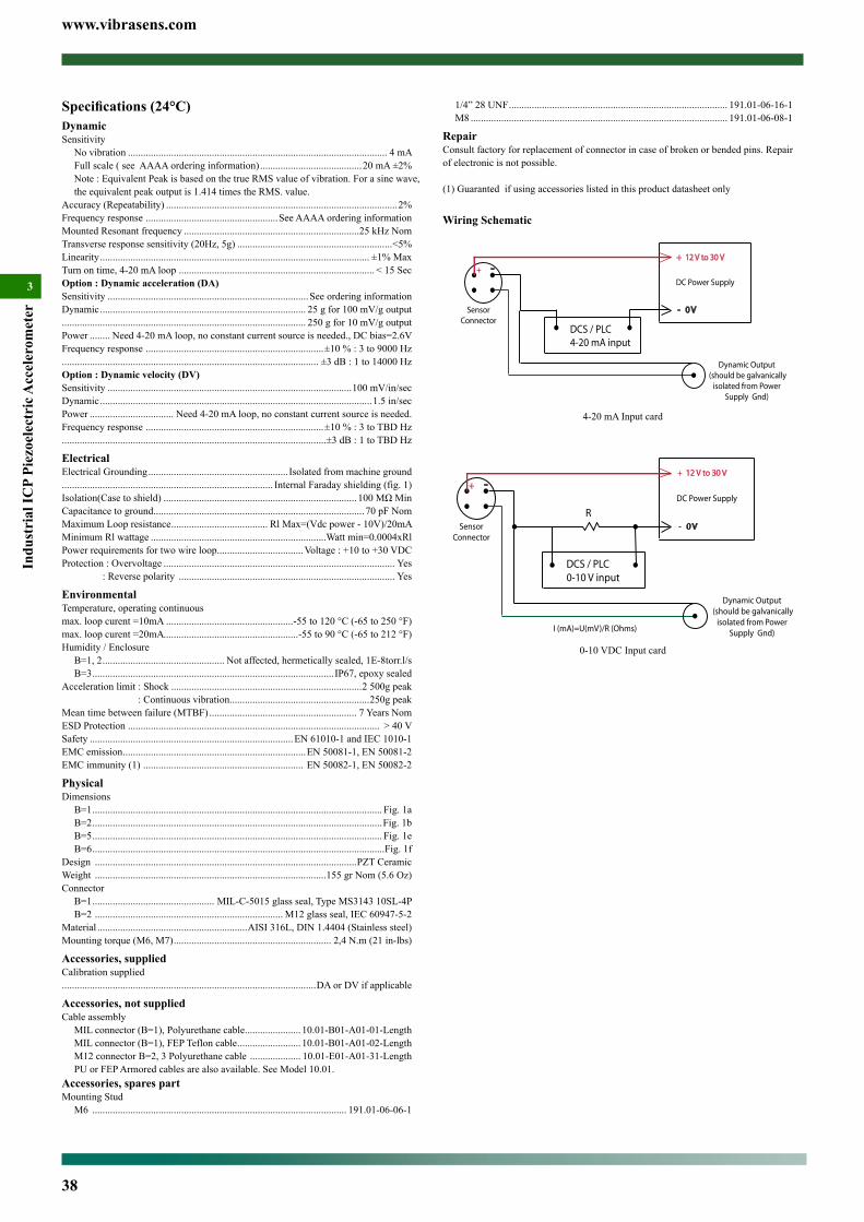
www.vibrasens.com
38
Indu
stri
al IC
P Pi
ezoe
lect
ric A
ccel
erom
eter
3
1/4” 28 UNF ...................................................................................... 191.01-06-16-1M8 ..................................................................................................... 191.01-06-08-1
RepairConsult factory for replacement of connector in case of broken or bended pins. Repair of electronic is not possible.
(1) Guaranted if using accessories listed in this product datasheet only
Wiring Schematic
DCS / PLC4-20 mA input
SensorConnector
+ 12 V to 30 V
- 0 V
DC Power Supply
-+
Dynamic Output (should be galvanically
isolated from PowerSupply Gnd)
4-20 mA Input card
SensorConnector
+ 12 V to 30 V
- 0 V
DC Power Supply
-+
R
I (mA)=U(mV)/R (Ohms)
DCS / PLC0-10 V input
Dynamic Output (should be galvanically
isolated from PowerSupply Gnd)
0-10 VDC Input card
Specifications (24°C)DynamicSensitivity
No vibration ...................................................................................................... 4 mAFull scale ( see AAAA ordering information) ........................................20 mA ±2%Note : Equivalent Peak is based on the true RMS value of vibration. For a sine wave, the equivalent peak output is 1.414 times the RMS. value.
Accuracy (Repeatability) ...........................................................................................2%Frequency response ....................................................See AAAA ordering informationMounted Resonant frequency .....................................................................25 kHz NomTransverse response sensitivity (20Hz, 5g) .............................................................<5%Linearity .......................................................................................................... ±1% MaxTurn on time, 4-20 mA loop ............................................................................. < 15 SecOption : Dynamic acceleration (DA)Sensitivity ...............................................................................See ordering informationDynamic ................................................................................. 25 g for 100 mV/g output................................................................................................ 250 g for 10 mV/g outputPower ........ Need 4-20 mA loop, no constant current source is needed., DC bias=2.6V Frequency response ......................................................................±10 % : 3 to 9000 Hz ..................................................................................................... ±3 dB : 1 to 14000 HzOption : Dynamic velocity (DV)Sensitivity ................................................................................................100 mV/in/secDynamic ...........................................................................................................1.5 in/secPower ................................. Need 4-20 mA loop, no constant current source is needed. Frequency response ......................................................................±10 % : 3 to TBD Hz ........................................................................................................±3 dB : 1 to TBD Hz
ElectricalElectrical Grounding ....................................................... Isolated from machine ground................................................................................... Internal Faraday shielding (fig. 1)Isolation(Case to shield) ............................................................................100MΩMinCapacitance to ground ................................................................................... 70 pF NomMaximum Loop resistance ...................................... Rl Max=(Vdc power - 10V)/20mAMinimum Rl wattage .....................................................................Watt min=0.0004xRlPower requirements for two wire loop ..................................Voltage : +10 to +30 VDCProtection : Overvoltage ........................................................................................... Yes : Reverse polarity ..................................................................................... Yes
EnvironmentalTemperature, operating continuous max. loop curent =10mA ..................................................-55 to 120 °C (-65 to 250 °F)max. loop curent =20mA.....................................................-55 to 90 °C (-65 to 212 °F)Humidity / Enclosure
B=1, 2 ................................................ Not affected, hermetically sealed, 1E-8torr.l/s B=3 ............................................................................................... IP67, epoxy sealed
Acceleration limit : Shock ...........................................................................2 500g peak : Continuous vibration.......................................................250g peakMean time between failure (MTBF) .......................................................... 7 Years NomESD Protection ................................................................................................... > 40 VSafety ................................................................................EN 61010-1 and IEC 1010-1EMC emission ........................................................................EN 50081-1, EN 50081-2EMC immunity (1) ............................................................... EN 50082-1, EN 50082-2
PhysicalDimensions
B=1 .................................................................................................................. Fig. 1aB=2 ..................................................................................................................Fig. 1bB=5 .................................................................................................................. Fig. 1eB=6 ...................................................................................................................Fig. 1f
Design .......................................................................................................PZT CeramicWeight ...........................................................................................155 gr Nom (5.6 Oz)Connector
B=1 ................................................ MIL-C-5015 glass seal, Type MS3143 10SL-4PB=2 .......................................................................... M12 glass seal, IEC 60947-5-2
Material ...........................................................AISI 316L, DIN 1.4404 (Stainless steel)Mounting torque (M6, M7) .............................................................. 2,4 N.m (21 in-lbs)
Accessories, suppliedCalibration supplied....................................................................................................DA or DV if applicable
Accessories, not suppliedCable assembly
MIL connector (B=1), Polyurethane cable ...................... 10.01-B01-A01-01-LengthMIL connector (B=1), FEP Teflon cable ......................... 10.01-B01-A01-02-LengthM12 connector B=2, 3 Polyurethane cable .................... 10.01-E01-A01-31-LengthPU or FEP Armored cables are also available. See Model 10.01.
Accessories, spares partMounting Stud
M6 .................................................................................................... 191.01-06-06-1
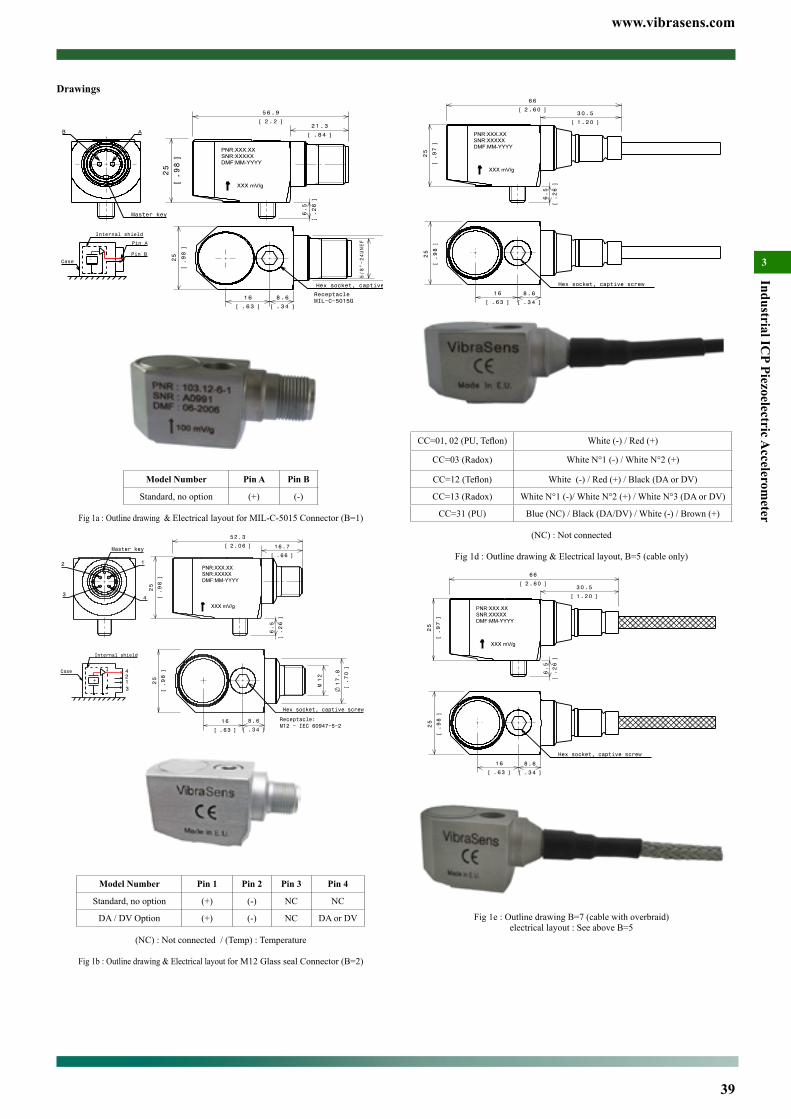
www.vibrasens.com
39
Industrial ICP Piezoelectric A
ccelerometer
3
Hex socket, captive screw
8.6
.34[ ]
16
.63[ ]
25
.98
[]
25
.97
[]
6 6
2.60[ ]
6.5
.26
[]
3 0.5
1.20[ ]
CC=01,02(PU,Teflon) White (-) / Red (+)
CC=03 (Radox) White N°1 (-) / White N°2 (+)
CC=12(Teflon) White (-) / Red (+) / Black (DA or DV)
CC=13 (Radox) White N°1 (-)/ White N°2 (+) / White N°3 (DA or DV)
CC=31 (PU) Blue (NC) / Black (DA/DV) / White (-) / Brown (+)
(NC) : Not connected
Fig 1d : Outline drawing & Electrical layout, B=5 (cable only)
25
.97
[]
6 6
2.60[ ]
6.5
.26
[]
3 0.5
1.20[ ]
Hex socket, captive screw
8.6
.34[ ]
16
.63[ ]
25
.98
[]
Fig 1e : Outline drawing B=7 (cable with overbraid)electrical layout : See above B=5
Drawings
25
.98
[]
6.5
.26
[]
5 6.9
2.2[ ]21.3
.84[ ]
17.8
.70
[]
25
.98
[]
8 .6
.34[ ]
5/8"−24UNEF
1 6
.63[ ]
Hex socket, captive screw
ReceptacleMIL−C−5015G
B A
Master key
Internal shield
Case −+
Pin A
Pin B
Model Number Pin A Pin B
Standard, no option (+) (-)
Fig 1a : Outline drawing & Electrical layout for MIL-C-5015 Connector (B=1)
−+
3
4
12
Internal shield
Case
25
.98
[]
12
M 17.8
.70
[]
1 6
.63[ ]
8.6
.34[ ]
Receptacle:M12 − IEC 60947−5−2
Hex socket, captive screw
6.5
.26
[]
25
.98
[]
5 2.3
2.06[ ] 16.7
.66[ ]
2 1
43
Master key
Model Number Pin 1 Pin 2 Pin 3 Pin 4
Standard, no option (+) (-) NC NC
DA / DV Option (+) (-) NC DA or DV
(NC) : Not connected / (Temp) : Temperature
Fig 1b : Outline drawing & Electrical layout for M12 Glass seal Connector (B=2)
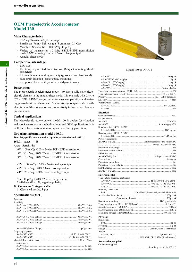
www.vibrasens.com
40
Indu
stri
al IC
P Pi
ezoe
lect
ric A
ccel
erom
eter
3
AAA=I3X..................................................................................................... 800 g pkAAA=V3X (5 VDC supply) .......................................................................... 25 g pkAA=V5X (5 VDC supply) ............................................................................. 50 g pkAA=V4V (5 VDC supply) ........................................................................... 100 g pkAA=P3V .............................................................................................Not Applicable
Transverse response sensitivity (20Hz, 5g) .............................................................<5%Temperature response (sensitivity) ...................................................... +12% at 120 °CPolarity .....................................................................................(fig. 1) Suffix dependantLinearity .......................................................................................................... ±1% MaxWarm up time (Typical)
AA=IXX, VXX ..............................................................................< 2 Sec (Typical)AA=P3V ...............................................................................................................N/A
ElectricalOutput impedance ..............................................................................................<100ΩDC output biasAA=IXX .................................................................................................... 12 VDC±2% AA=VXX ........................................................................................ 0.5 x Vsupply ±2% Residual noise (24°C) : A=IXX
1 Hz to 25 kHz ....................................................................................... TBD ug rmsResidual noise (24°C) : A=VXX
1 Hz to 25 kHz ..................................................................................... TBD ug rmsPower requirements :AA=IXX (Fig 2a) ..................................................Constant current : +2 to +10mA DC...............................................................................................Voltage : +22 to +28 VDCProtection, overvoltage ............................................................................................. YesProtection, reverse polarity ...................................................................................... YesESD Protection .................................................................................................... > 20VAA=VXX (Fig 2b) ....................................................................Voltage : +3 to +5 VDCCurrent draw ..................................................................................................1 mA maxProtection, overvoltage ............................................................................................. YesProtection, reverse polarity ....................................................................................... NoESD Protection ...................................................................................................... noneAA=P3V (Fig 2c) ................................................................................................... none
EnvironmentalTemperature, operating continuous
AA= IXX ......................................................................-55 to 120 °C (-65 to 250°F)AA= VXX ....................................................................-55 to 120 °C (-65 to 250 °F)A=PXX.........................................................................-55 to 120 °C (-65 to 250 °F)
Humidity / EnclosureB=1 .................................................... Not affected, hermetically sealed, 1E-8torr.l/s
Acceleration limit : Shock ...........................................................................5 000g peak : Continuous vibration.......................................................500g peakBase strain sensitivity ........................................................................ TBD g pk/u strainTemp. transient sens. (3Hz, LLF, 20dB/dec) .................................................0.8 mg/°C Acoustic sensitivity (164 dBSP) ....................................................................... TBD mg Electromagnetic sens. (50Hz, 0.03 T) ................................................................. TBD gMean time between failure (MTBF) ........................................................ 10 Years Nom
PhysicalDimensions
B=1 .................................................................................................................. Fig. 1aMounting ...............................................................................................................Fig 1bDesign ............................................................................. Ceramic, annular shear modeWeight
AA=2X, 3X, 41 .............................................................................3 gr Nom (0.1 Oz)Material ...........................................................AISI 304L, DIN 1.4306 (Stainless steel)
Accessories, suppliedCalibration supplied........................................................................................ Sensitivity check (5g, 160 Hz)
OEM Piezoelectric Accelerometer Model 160Main Characteristics• T0-5 eq. Transistor-Style Package• Small size (9mm), light weight (3 grammes, 0.1 Oz)• Variety of Sensitivities : 100 mV/g, 11 pC/g, ...• Variety of transmission : 2-Wire ®ICP/®IEPE transmission
mode / 3-Wire Voltage output / 2-wire charge output• Annular shear mode
Competitive advantage• Low Cost• Electronic is protected from Overload (Magnet mounting, shock
protected)• life time hermetic sealing warranty (glass seal and laser weld)• base strain isolation (easier epoxy mounting)• exceptional bias stability (improved dynamic range)
DescriptionThe piezoelectric accelerometer model 160 uses a solid-state piezo-electric element in the annular shear mode. It is available with 2-wire ICP - IEPE - LIVM Voltage output for easy compatibility with exist-ing piezoelectric accelerometer. 3-wire Voltage output is also avail-able for simplified operation and connectivity to low power data ac-quisition unit.
Typical applicationsThe piezoelectric accelerometer model 160 is design for vibration and shock measurements in high-volume and OEM applications. It is well suited for vibration monitoring and machinery protection.
Ordering information model 160.01To order, specify model number, options, accessories and suffix :
160.01- AAA - B AAA : Sensitivity
I6V : 100 mV/g ±20% / 2-wire ICP-IEPE transmissionI5V : 50 mV/g ±20% / 2-wire ICP-IEPE transmissionI3V : 10 mV/g ±20% / 2-wire ICP-IEPE transmission
V6V : 100 mV/g ±20% / 3-wire voltage outputV5V : 50 mV/g ±20% / 3-wire voltage outpuV4V : 25 mV/g ±20% / 3-wire voltage output
P3V: 11 pC/g ± 20% / 2 wire charge outputAvailable suffix : N, negative polarity
B : Connector / Integral cable1 : Glass seal header, 3-pin
Specifications (24°C)DynamicSensitivity
AAA=I6V (2-Wire ICP) ..................................................................100 mV/g ±20%AAA=I5V (2-Wire ICP) ....................................................................50 mV/g ±20%AAA=I3V (2-Wire ICP) ....................................................................10 mV/g ±20%
AAA=V6V (3-wire Voltage) ............................................................100 mV/g ±20%AAA=V5V (3-wire Voltage) ..............................................................50 mV/g ±20%AAA=V4V (3-wire Voltage) ..............................................................25 mV/g ±20%
AAA=P3V (2-Wire Charge) ............................................................... 11 pC/g ±20%Frequency response
AAA=IXX, VXX .................................................................. ±1 dB : 1 to 10 000 HzAAA=IXX, VXX ............................................................... ±3 dB : 0.4 to 20 000 Hz
Mounted Resonant frequency .................................................................. >42 kHz NomDynamic range
AAA=I6X....................................................................................................... 80 g pkAAA=I5X..................................................................................................... 160 g pk
Model 160.01-AAA-1
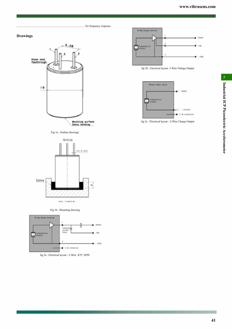
www.vibrasens.com
41
Industrial ICP Piezoelectric A
ccelerometer
3
fig2b:Electricallayout-3WireVoltageOutput
fig2c:Electricallayout-2-WireChargeOutput
.................................................................................................... No frequency response
Drawings
Fig 1a : Outline drawing)
Fig 1b : Mounting drawing
fig2a:Electricallayout-2-WireICP/IEPE
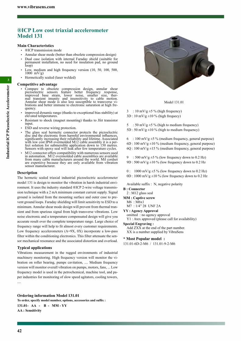
www.vibrasens.com
42
Indu
stri
al IC
P Pi
ezoe
lect
ric A
ccel
erom
eter
3
3 : 10 mV/g ±5 % (high frequency)3D : 10 mV/g ±10 % (high frequecy)
5 : 50 mV/g ±5 % (high to medium frequency)5D : 50 mV/g ±10 % (high to medium frequency)
6 : 100 mV/g ±5 % (medium frequency, general purpose)6D : 100 mV/g ±10 % (medium frequency, general purpose)6Q : 100 mV/g ±15 % (medium frequency, general purpose)
9 : 500 mV/g ±5 % (low frequency down to 0.2 Hz)9D : 500 mV/g ±10 % (low frequency down to 0.2 Hz
0 : 1000 mV/g ±5 % (low frequency down to 0.2 Hz)0D : 1000 mV/g ±10 % (low frequency down to 0.2 Hz
Available suffix : N, negative polarityB : Connector
2 : M12 glass sealMM : Captive screw
M6 : M6x1M7 : 1/4” 28 UNF 2A
YY : Agency Approvalomitted : no agency approvalY1 : Atex approved (please call for availability)
Special Engraving :Add ZXX at the end of the part number.XX is a number supplied by VibraSens
* Most Popular model :131.01-6D-2-M6 / 131.01-9-2-M6
®ICP Low cost triaxial accelerometer Model 131 Main Characteristics• ®ICP transmission mode• Annular shear mode (better than obsolete compression design)• Dual case isolation with internal Faraday shield (suitable for
permanent installation, no need for insulation pad, no ground loop)
• Low, medium and high frequency version (10, 50, 100, 500, 1000 mV/g)
• Hermetically sealed (laser welded)
Competitive advantage• Compare to obsolete compression design, annular shear
piezoelectric sensors feature better frequency response, improved base strain, lower noise, smaller size, ther-mal transient imunity and insensitivity to cable motion. Annular shear mode is also less susceptible to transverse vi-brations and better immune to electronic saturation at high fre-quency.
• improved dynamic range (thanks to exceptional bias stability) at elevated temperatures.
• Resistant to shock (magnet mounting) thanks to Jfet transistor input.
• ESD and reverse wiring protection.• The glass seal hermetic connector protects the piezoelectric discandtheelectronicfromharmfulenvironmentalinfluences,significantlyincreasingtheirreliabilityandlifetime.Associatedwith low cost IP68 overmolded M12 cable assembly it is a per-fect solution for submersible application down to 150 metres. Sensors with epoxy seal will leak after few temperature cycles.
• M12 connector offers compatibility with numerous sensors used in automation. M12 overmolded cable assemblies are available from many cable manufacturers around the world. Mil cordset are expensive because they are only available from vibration sensor manufacturer.
DescriptionThe hermetic sealed triaxial industrial piezoelectric accelerometer model 131 is design to monitor the vibration in harsh industrial envi-ronment. It uses the industry standard ®ICP 2-wire voltage transmis-sion technique with a 2 mA minimum constant current supply. Signal ground is isolated from the mounting surface and outer case to pre-vent ground loops. Faraday shielding will limit sensitivity to ESD to a minimum. Annular shear mode design will prevent from thermal tran-sient and from spurious signal from high transverse vibrations. Low noise electronic and a temperature compensated design will give you accurate result over the complete temperature range. Large choice of frequency range will help to fit almost every customer requirements. Low frequency accelerometers (A=9X, 0X) incorporate a low-pass filter within the conditioning electronics. This filter attenuate the sen-sor mechanical resonance and the associated distortion and overload.
Typical applicationsVibrations measurement in the rugged environments of industrial machinery monitoring. High frequency version will monitor the vi-bration on roller bearing, pumps cavitation, .... Medium frequency version will monitor overall vibration on pumps, motors, fans, ... Low frequency model is used in the petrochemical, machine tool, and pa-per industries for monitoring of slow speed agitators, cooling towers, ....
Ordering information Model 131.01To order, specify model number, options, accessories and suffix :
131.01- AA - B - MM - YYAA : Sensitivity
Model 131.01
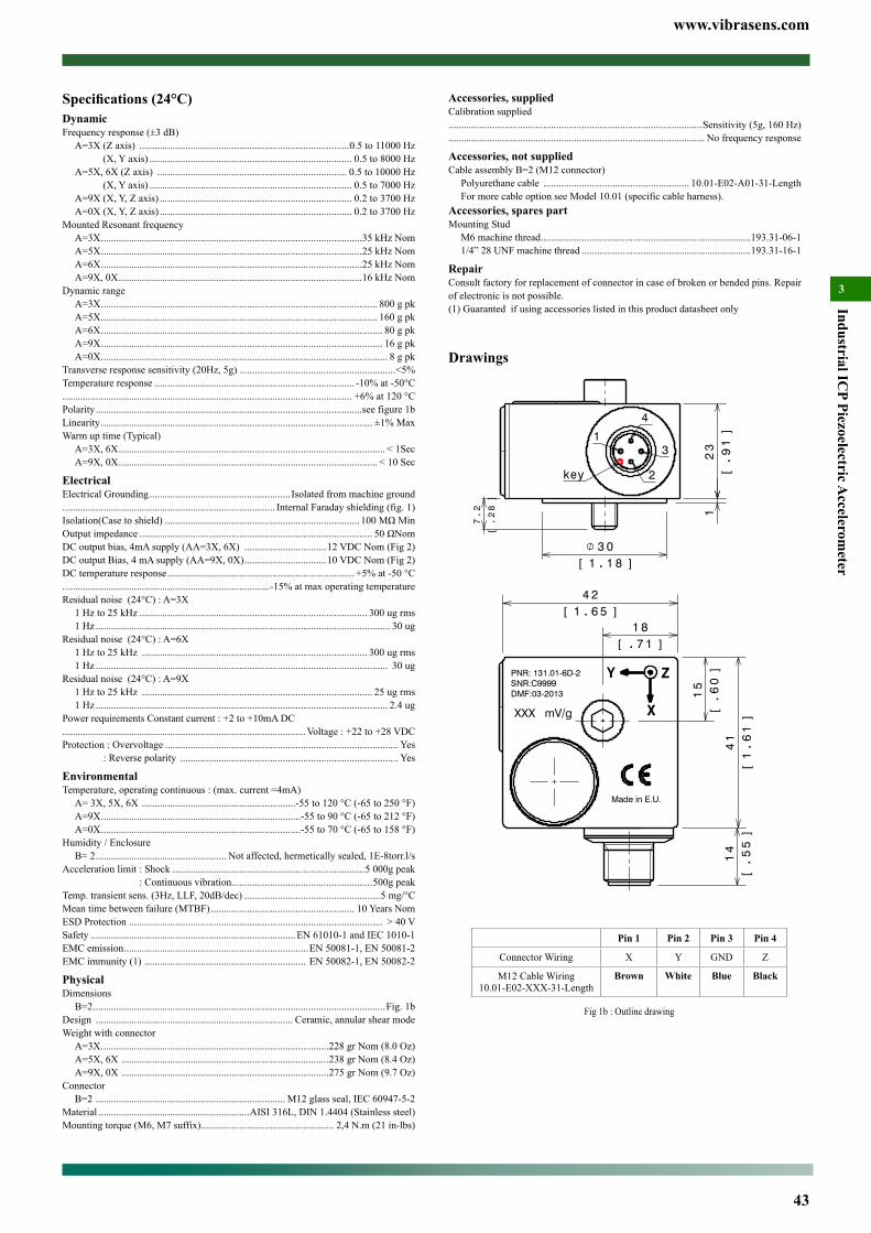
www.vibrasens.com
43
Industrial ICP Piezoelectric A
ccelerometer
3
Accessories, suppliedCalibration supplied...................................................................................................Sensitivity (5g, 160 Hz).................................................................................................... No frequency response
Accessories, not suppliedCable assembly B=2 (M12 connector)
Polyurethane cable ......................................................... 10.01-E02-A01-31-LengthFor more cable option see Model 10.01 (specific cable harness).
Accessories, spares partMounting Stud
M6 machine thread ..................................................................................193.31-06-11/4” 28 UNF machine thread ..................................................................193.31-16-1
RepairConsult factory for replacement of connector in case of broken or bended pins. Repair of electronic is not possible.(1) Guaranted if using accessories listed in this product datasheet only
Drawings
Pin 1 Pin 2 Pin 3 Pin 4
Connector Wiring X Y GND Z
M12 Cable Wiring10.01-E02-XXX-31-Length
Brown White Blue Black
Fig 1b : Outline drawing
Specifications (24°C)DynamicFrequency response (±3 dB)
A=3X (Z axis) ..................................................................................0.5 to 11000 Hz (X, Y axis) ............................................................................... 0.5 to 8000 HzA=5X, 6X (Z axis) .......................................................................... 0.5 to 10000 Hz (X, Y axis) ............................................................................... 0.5 to 7000 HzA=9X (X, Y, Z axis) ........................................................................... 0.2 to 3700 HzA=0X (X, Y, Z axis) ........................................................................... 0.2 to 3700 Hz
Mounted Resonant frequencyA=3X ......................................................................................................35 kHz NomA=5X ......................................................................................................25 kHz NomA=6X ......................................................................................................25 kHz NomA=9X, 0X ...............................................................................................16 kHz Nom
Dynamic rangeA=3X ............................................................................................................ 800 g pkA=5X ............................................................................................................ 160 g pkA=6X .............................................................................................................. 80 g pkA=9X .............................................................................................................. 16 g pkA=0X ................................................................................................................ 8 g pk
Transverse response sensitivity (20Hz, 5g) .............................................................<5%Temperature response .............................................................................. -10% at -50°C................................................................................................................. +6% at 120 °CPolarity ........................................................................................................see figure 1bLinearity .......................................................................................................... ±1% MaxWarm up time (Typical)
A=3X, 6X ........................................................................................................ < 1SecA=9X, 0X ..................................................................................................... < 10 Sec
ElectricalElectrical Grounding ....................................................... Isolated from machine ground................................................................................... Internal Faraday shielding (fig. 1)Isolation(Case to shield) ............................................................................100MΩMinOutput impedance ........................................................................................... 50ΩNomDC output bias, 4mA supply (AA=3X, 6X) ................................12 VDC Nom (Fig 2)DC output Bias, 4 mA supply (AA=9X, 0X) ................................10 VDC Nom (Fig 2)DC temperature response ......................................................................... +5% at -50 °C.................................................................................-15% at max operating temperatureResidual noise (24°C) : A=3X
1 Hz to 25 kHz ......................................................................................... 300 ug rms1 Hz ................................................................................................................... 30 ug
Residual noise (24°C) : A=6X1 Hz to 25 kHz ........................................................................................ 300 ug rms1 Hz .................................................................................................................. 30 ug
Residual noise (24°C) : A=9X1 Hz to 25 kHz .......................................................................................... 25 ug rms1 Hz .................................................................................................................. 2.4 ug
Power requirements Constant current : +2 to +10mA DC...............................................................................................Voltage : +22 to +28 VDCProtection : Overvoltage ........................................................................................... Yes : Reverse polarity ..................................................................................... Yes
EnvironmentalTemperature, operating continuous : (max. current =4mA)
A= 3X, 5X, 6X ............................................................-55 to 120 °C (-65 to 250 °F)A=9X ..............................................................................-55 to 90 °C (-65 to 212 °F)A=0X ..............................................................................-55 to 70 °C (-65 to 158 °F)
Humidity / EnclosureB= 2 ................................................... Not affected, hermetically sealed, 1E-8torr.l/s
Acceleration limit : Shock ...........................................................................5 000g peak : Continuous vibration.......................................................500g peakTemp. transient sens. (3Hz, LLF, 20dB/dec) .....................................................5 mg/°C Mean time between failure (MTBF) ........................................................ 10 Years NomESD Protection ................................................................................................... > 40 VSafety ................................................................................EN 61010-1 and IEC 1010-1EMC emission ........................................................................EN 50081-1, EN 50081-2EMC immunity (1) ............................................................... EN 50082-1, EN 50082-2
PhysicalDimensions
B=2 ..................................................................................................................Fig. 1bDesign ............................................................................. Ceramic, annular shear modeWeight with connector
A=3X .........................................................................................228 gr Nom (8.0 Oz)A=5X, 6X .................................................................................238 gr Nom (8.4 Oz)A=9X, 0X .................................................................................275 gr Nom (9.7 Oz)
ConnectorB=2 .......................................................................... M12 glass seal, IEC 60947-5-2
Material ...........................................................AISI 316L, DIN 1.4404 (Stainless steel)Mounting torque (M6, M7 suffix).................................................... 2,4 N.m (21 in-lbs)
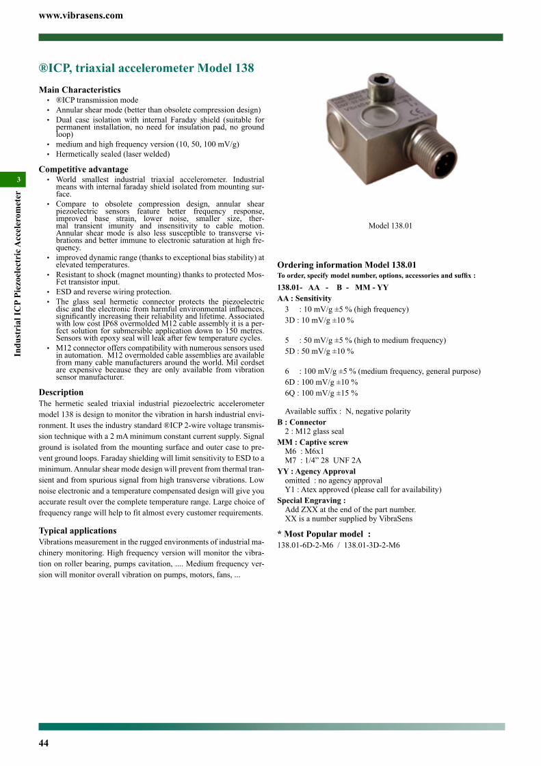
www.vibrasens.com
44
Indu
stri
al IC
P Pi
ezoe
lect
ric A
ccel
erom
eter
3
Ordering information Model 138.01To order, specify model number, options, accessories and suffix :
138.01- AA - B - MM - YYAA : Sensitivity
3 : 10 mV/g ±5 % (high frequency)3D : 10 mV/g ±10 %
5 : 50 mV/g ±5 % (high to medium frequency)5D : 50 mV/g ±10 %
6 : 100 mV/g ±5 % (medium frequency, general purpose)6D : 100 mV/g ±10 %6Q : 100 mV/g ±15 %
Available suffix : N, negative polarityB : Connector
2 : M12 glass sealMM : Captive screw
M6 : M6x1M7 : 1/4” 28 UNF 2A
YY : Agency Approvalomitted : no agency approvalY1 : Atex approved (please call for availability)
Special Engraving :Add ZXX at the end of the part number.XX is a number supplied by VibraSens
* Most Popular model :138.01-6D-2-M6 / 138.01-3D-2-M6
®ICP, triaxial accelerometer Model 138 Main Characteristics• ®ICP transmission mode• Annular shear mode (better than obsolete compression design)• Dual case isolation with internal Faraday shield (suitable for
permanent installation, no need for insulation pad, no ground loop)
• medium and high frequency version (10, 50, 100 mV/g)• Hermetically sealed (laser welded)
Competitive advantage• World smallest industrial triaxial accelerometer. Industrial
means with internal faraday shield isolated from mounting sur-face.
• Compare to obsolete compression design, annular shear piezoelectric sensors feature better frequency response, improved base strain, lower noise, smaller size, ther-mal transient imunity and insensitivity to cable motion. Annular shear mode is also less susceptible to transverse vi-brations and better immune to electronic saturation at high fre-quency.
• improved dynamic range (thanks to exceptional bias stability) at elevated temperatures.
• Resistant to shock (magnet mounting) thanks to protected Mos-Fet transistor input.
• ESD and reverse wiring protection.• The glass seal hermetic connector protects the piezoelectric discandtheelectronicfromharmfulenvironmentalinfluences,significantlyincreasingtheirreliabilityandlifetime.Associatedwith low cost IP68 overmolded M12 cable assembly it is a per-fect solution for submersible application down to 150 metres. Sensors with epoxy seal will leak after few temperature cycles.
• M12 connector offers compatibility with numerous sensors used in automation. M12 overmolded cable assemblies are available from many cable manufacturers around the world. Mil cordset are expensive because they are only available from vibration sensor manufacturer.
DescriptionThe hermetic sealed triaxial industrial piezoelectric accelerometer model 138 is design to monitor the vibration in harsh industrial envi-ronment. It uses the industry standard ®ICP 2-wire voltage transmis-sion technique with a 2 mA minimum constant current supply. Signal ground is isolated from the mounting surface and outer case to pre-vent ground loops. Faraday shielding will limit sensitivity to ESD to a minimum. Annular shear mode design will prevent from thermal tran-sient and from spurious signal from high transverse vibrations. Low noise electronic and a temperature compensated design will give you accurate result over the complete temperature range. Large choice of frequency range will help to fit almost every customer requirements.
Typical applicationsVibrations measurement in the rugged environments of industrial ma-chinery monitoring. High frequency version will monitor the vibra-tion on roller bearing, pumps cavitation, .... Medium frequency ver-sion will monitor overall vibration on pumps, motors, fans, ...
Model 138.01
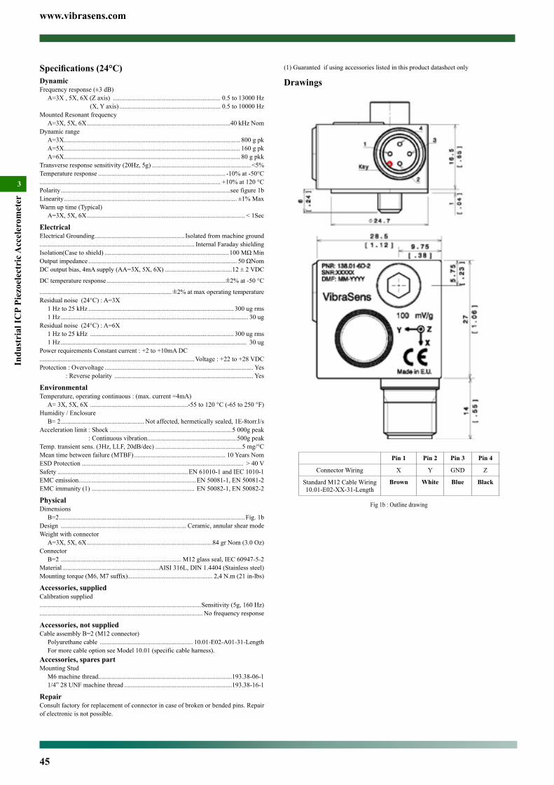
www.vibrasens.com
45
Indu
stri
al IC
P Pi
ezoe
lect
ric A
ccel
erom
eter
3
(1) Guaranted if using accessories listed in this product datasheet only
Drawings
Pin 1 Pin 2 Pin 3 Pin 4
Connector Wiring X Y GND Z
Standard M12 Cable Wiring10.01-E02-XX-31-Length
Brown White Blue Black
Fig 1b : Outline drawing
Specifications (24°C)DynamicFrequency response (±3 dB)
A=3X , 5X, 6X (Z axis) .................................................................. 0.5 to 13000 Hz (X, Y axis) .............................................................. 0.5 to 10000 Hz
Mounted Resonant frequencyA=3X, 5X, 6X ........................................................................................40 kHz Nom
Dynamic rangeA=3X ............................................................................................................ 800 g pkA=5X ............................................................................................................ 160 g pkA=6X ............................................................................................................ 80 g pkk
Transverse response sensitivity (20Hz, 5g) .............................................................<5%Temperature response .............................................................................. -10% at -50°C............................................................................................................... +10% at 120 °CPolarity ........................................................................................................see figure 1bLinearity .......................................................................................................... ±1% MaxWarm up time (Typical)
A=3X, 5X, 6X ................................................................................................. < 1Sec
ElectricalElectrical Grounding ....................................................... Isolated from machine ground............................................................................................... Internal Faraday shieldingIsolation(Case to shield) ............................................................................100MΩMinOutput impedance ........................................................................................... 50ΩNomDC output bias, 4mA supply (AA=3X, 5X, 6X) .........................................12 ± 2 VDC
DC temperature response .........................................................................±2% at -50 °C
.................................................................................±2% at max operating temperatureResidual noise (24°C) : A=3X
1 Hz to 25 kHz ......................................................................................... 300 ug rms1 Hz ................................................................................................................... 30 ug
Residual noise (24°C) : A=6X1 Hz to 25 kHz ........................................................................................ 300 ug rms1 Hz .................................................................................................................. 30 ug
Power requirements Constant current : +2 to +10mA DC...............................................................................................Voltage : +22 to +28 VDCProtection : Overvoltage ........................................................................................... Yes : Reverse polarity ..................................................................................... Yes
EnvironmentalTemperature, operating continuous : (max. current =4mA)
A= 3X, 5X, 6X ............................................................-55 to 120 °C (-65 to 250 °F)Humidity / Enclosure
B= 2 ................................................... Not affected, hermetically sealed, 1E-8torr.l/s Acceleration limit : Shock ...........................................................................5 000g peak : Continuous vibration.......................................................500g peakTemp. transient sens. (3Hz, LLF, 20dB/dec) .....................................................5 mg/°C Mean time between failure (MTBF) ........................................................ 10 Years NomESD Protection ................................................................................................... > 40 VSafety ................................................................................EN 61010-1 and IEC 1010-1EMC emission ........................................................................EN 50081-1, EN 50081-2EMC immunity (1) ............................................................... EN 50082-1, EN 50082-2
PhysicalDimensions
B=2 ..................................................................................................................Fig. 1bDesign ............................................................................. Ceramic, annular shear modeWeight with connector
A=3X, 5X, 6X .............................................................................84 gr Nom (3.0 Oz)Connector
B=2 .......................................................................... M12 glass seal, IEC 60947-5-2Material ...........................................................AISI 316L, DIN 1.4404 (Stainless steel)Mounting torque (M6, M7 suffix).................................................... 2,4 N.m (21 in-lbs)
Accessories, suppliedCalibration supplied...................................................................................................Sensitivity (5g, 160 Hz).................................................................................................... No frequency response
Accessories, not suppliedCable assembly B=2 (M12 connector)
Polyurethane cable ......................................................... 10.01-E02-A01-31-LengthFor more cable option see Model 10.01 (specific cable harness).
Accessories, spares partMounting Stud
M6 machine thread ..................................................................................193.38-06-11/4” 28 UNF machine thread ..................................................................193.38-16-1
RepairConsult factory for replacement of connector in case of broken or bended pins. Repair of electronic is not possible.

www.vibrasens.com
46
Mou
ntin
g &
Acc
esso
ries
4
Contents
Stud, Non Isolated, Model 191 ....................................................47
Bolt, captive, Hex socket, Model 193 ..........................................49
Bolt, captive, Hexagonal, Model 194 ..........................................50
Flat magnet, Model 210 ...............................................................51
Flat magnet, Model 211 ...............................................................52
Flat magnet, Model 212 ...............................................................53
Curved magnet, Model 220 .........................................................54
Curved magnet, Model 221 .........................................................55
Magnetic mounting pad, Model 208 ...........................................56
Cementing - Adhesive pad, Model 202 .......................................57
Cementing - Adhesive pad, Model 204 .......................................58
Cementing - Adhesive pad, Model 206 .......................................59

www.vibrasens.com
47
Mounting &
Accessories
4
Model 191.01-06-1
SpecificationsEnvironmental
TemperatureC=1, 2 ..................................................................... -70°Cto 260 °C (-436 to 500 °F)C=3 .........................................................................-260 to 700 °C (-436 to 1292 °F)
PhysicalDimensions ..................................................................................... See outline drawingWeight ............................................................................................between 1.5 and 3 gr................................................................................................. between 0.05 and 0.1 OzMaterial
C=1 .................................................AISI 303, DIN1.4301, AFNOR Z10 CNF 18 09C=2 ................................................AISI 316L, DIN1.4404, AFNOR Z2 CND 17 13 C=3 ...................................................................................Nimonic 90, WNR 2.4969
Mounting torqueAA=05, 15 or BB=05, 15 ............................................................... 2 N.m (18 in-lbs)AA=06, 16 or BB=06, 16 ............................................................ 2.7 N.m (24 in-lbs)
Outline drawing
See table below to check the associated drawing
BB (Machine)
05 06 08 15 16
M5x
0.8
M6x
1
M8x
1.25
10-3
2 U
NF
2A
1/4
28 U
NF
2A
AA
(sen
sor)
05 M5x0.8 Fig 11 Fig 12 Fig 13 Fig 14
06 M6x1 Fig 21 Fig 22 Fig 23 Fig 24 Fig 25
15 10-32 UNF 2A
Fig 31 Fig 32 Fig 33 Fig 34
16 1/4 28 UNF 2A
Fig 41 Fig 42 Fig 43 Fig 44 Fig 45
Stud, Non Isolated, Model 191Main Characteristics• -260°C to 700 °C (-436°F to 1292°F) (options dependant)• Large choice of options for material and thread• For top connector accelerometer model 101 and 105
DescriptionThis is the most usual method for accelerometer mounting. These studs are detacheable, permiting rapid, low cost replacement. They are used by most accelerometer manufacturers but they are not fully compatible due to the sensor shoulder diameter and the thread length . You should not use ordinary machine screw because they lack a flange or shoulder and might bottom in the accelerometer and de-grades his dynamic response. Stud mounting is considered as the most reliable way to mount a vibration sensor. Stud mounting will attain the maximum sensor frequency range. Stud mountind requires a tapped hole drilled directly into the structure. The sensor requires a flat spot faced surface with a perpendicular tapped hole.
Ordering informationTo order, specify part number, options and suffix :191.01- AA - B B - C (Mod)AA : Sensor end
05 - M5x0.806 - M6x115 - 10-32 UNF 2A16 - 1/4 28 UNF 2A
BB : Machine/Structure end05 - M5x0.806 - M6x108 - M8x1.2515 - 10-32 UNF 2A16 - 1/4 28 UNF 2A
C : Material1 - Aisi 3032 - Aisi 316L3 - Nimonic 90
(Mod)(Mod)** : modification defined by customers. For example shoulder diameter.
Ordering example191.01-05-05-1 Stud, non isolated
Stocked models :191.01-15-15-1 / 191.01-15-05-1 / 191.01-06-06-1 / 191.01-06-16-1 / 191.01-06-08-1 / 191.01-16-06-1 / 191.01-16-16-1 / 191.01-16-08-1
Competitor’s cross reference list
VibraSens Ref. Competitor’s Ref.
191.01-16-16-1 Wilcoxon SF6, PCB 081B20
191.01-16-06-1 PCB M081B20
191.01-15-15-1 Wilcoxon SF1, Endevco 2984-2, PCB 081B05
191.01-15-05-1 PCB M081B23
191.01-15-06-1 PCB M081B05
191.01-15-16-1 Wilcoxon SF3, Endevco 22330, PCB 081A08
191.01-16-08-1 Wilcoxon SF6M,
191.01-16-06-1 Wilcoxon SF6M-1,
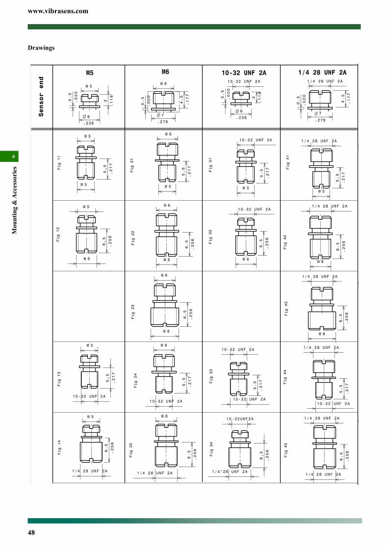
www.vibrasens.com
48
Mou
ntin
g &
Acc
esso
ries
4
Drawings

www.vibrasens.com
49
Mounting &
Accessories
4
Fig 21
Fig 41
Bolt, captive, Hex socket, Model 193Main Characteristics• -260°C to 260 °C (-436°F to 500°F)• Bolt for accelerometer model 103 and 107
DescriptionThis bolt is used to mount side connector industrial accelerometers ( model 103 and 107) with through hole mounting.
Ordering informationTo order, specify part number, options and suffix :193.01- AA - C (Mod)AA : Machine/Structure end
06 - M6x116 - 1/4 28 UNF 2A
C : Material1 - Aisi 3032 - Aisi 316L
(Mod)(Mod)** : modification defined by customers. For example shoulder diameter.
Ordering example193.01-06-1 Bolt, captive, Hex socket
Stocked models :193.01-06-1 and 193.01-16-1
SpecificationsEnvironmentalTemperature ..................................................................-260 to 260 °C (-436 to 500 °F)
PhysicalDimensions ..................................................................................... See outline drawingWeight ................................................................................................. ~7 gr (~ 0.25 Oz)
MaterialC=1 ......................................................AISI 303, DIN1.4301, AFNOR Z10 CNF 18 09C=2 .....................................................AISI 316L, DIN1.4435, AFNOR Z2 CND 17 13 Mounting torque ............................................................................... 2.7 N.m (24 in-lbs)
Outline drawingSee table below to check the associated drawing
AA Figures
M6x1 06 Fig 21
1/4 28 UNF 2A 16 Fig 41
Model 193.01-06-1

www.vibrasens.com
50
Mou
ntin
g &
Acc
esso
ries
4
Fig 11
Bolt, captive, Hexagonal, Model 194Main Characteristics• -260°C to 260 °C (-436°F to 500°F)• Bolt for accelerometer model 104
DescriptionThis bolt is used to mount side connector industrial accelerometers ( model 104) with through hole mounting.
Ordering informationTo order, specify part number, options and suffix :194.01- AA - C (Mod)AA : Machine/Structure end
08 - M8x1.25C : Material
1 - Aisi 3032 - Aisi 316L
(Mod)(Mod)** : modification defined by customers. For example shoulder diameter.
Ordering example194.01-08-1 Bolt, captive, Hex socket
Stocked models :194.01-08-1
SpecificationsEnvironmentalTemperature ..................................................................-260 to 260 °C (-436 to 500 °F)
PhysicalDimensions ..................................................................................... See outline drawingWeight ................................................................................................. ~9 gr (~ 0.35 Oz)
MaterialC=1 ......................................................AISI 303, DIN1.4301, AFNOR Z10 CNF 18 09C=2 .....................................................AISI 316L, DIN1.4435, AFNOR Z2 CND 17 13 Mounting torque ............................................................................... 2.7 N.m (24 in-lbs)
Outline drawingSee table below to check the associated drawing
AA Figures
M8x1.25 08 Fig 11
Model 194.01-08-1

www.vibrasens.com
51
Mounting &
Accessories
4
Outline drawing
4.5
3.2
A A
BB
Fig 1a
Mounting drawing
MagnetModel 210
MachineFlat spot
Fig 2a
Typical frequency response
1 10 100 1000
0
20
40
60
Sensi
tivity d
evia
tion (
%)
*
Frequency (Hz) 10k
100
80
-20
-40
-60
0
20
40
60
100
80
-20
-40
-60
Fig 4a
Flat magnet, Model 210Main Characteristics• portable route measurements• high temperature up to 200°C• for top connector sensors with M5 and 10-32 UNF thread• forflatsurfacesonly• Stainless steel
DescriptionThe use of magnet bases is convenient and quick for many appli-cations (route measurements). They produce an intimate and stiff contact between DC and few kilohertz. The high frequency response (above few kHz) is significantly distored. Obviously the machine surface should be magnetically attractive and free of paint chips and scale. Painted surface should use our stainless steel magnet target model 208 that greatly improve the high frequency response. We also recommend the use of coupling fluids, such as oil.Customer should pay attention to magnet attaching on the machine. The shock could overload the vibration sensor and destroy the elec-tronic.
Ordering informationTo order, specify part number, options and suffix :210.01- AA - BB AA : Sensor thread
05 - M5x0.815 - 10-32 UNF
BB : Diameter19 - 19 mm
Stocked models :210.01-15-19
Ordering example210.01-15-19 Flat magnet, 10-32 UNF
SpecificationsDynamicFrequency response ....................................................................... 10% : DC to 2.5 kHz.........................................................................................................................see fig 4a
EnvironmentalTemperature ...............................................................-55°C to 200 °C (-67°F to 320°F)
PhysicalDimensions .......................................................................... See outline drawing Fig 1aWeight ................................................................................................. ~9.5 gr (0.33 Oz)Material .....................................................................................................Stainless steelMagnet ..................................................................... high temperature rare eath magnetpull force ..................................................................................................23 kg (50 Lbs)
AccessoriesMagnet targets ................................................................................................ model 208
Competitors cross reference listWilcoxon B2a, B4 / CTC online TBD / PCB TBD / AMPO EMID 22 / Dytran
Model 210.01-15-19
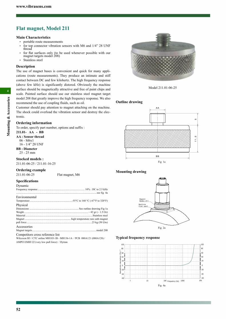
www.vibrasens.com
52
Mou
ntin
g &
Acc
esso
ries
4
Outline drawingAA
BB
11.5
5
Fig 1a
Mounting drawing
MachineFlat spot
Magnet Model 211
Fig 2a
Typical frequency response
1 10 100 1000
0
20
40
60
Sensi
tivity d
evia
tion (
%)
*
Frequency (Hz) 10k
100
80
-20
-40
-60
0
20
40
60
100
80
-20
-40
-60
Fig 4a
Flat magnet, Model 211Main Characteristics• portable route measurements• for top connector vibration sensors with M6 and 1/4” 28 UNF
thread• forflat surfaces only (to be usedwhenever possiblewith our
magnet targets model 208)• Stainless steel
DescriptionThe use of magnet bases is convenient and quick for many appli-cations (route measurements). They produce an intimate and stiff contact between DC and few kilohertz. The high frequency response (above few kHz) is significantly distored. Obviously the machine surface should be magnetically attractive and free of paint chips and scale. Painted surface should use our stainless steel magnet target model 208 that greatly improve the high frequency response. We also recommend the use of coupling fluids, such as oil.Customer should pay attention to magnet attaching on the machine. The shock could overload the vibration sensor and destroy the elec-tronic.
Ordering informationTo order, specify part number, options and suffix :211.01- AA - BB AA : Sensor thread
06 - M6x116 - 1/4” 28 UNF
BB : Diameter25 - 25 mm
Stocked models :211.01-06-25 / 211.01-16-25
Ordering example211.01-06-25 Flat magnet, M6
SpecificationsDynamicFrequency response ....................................................................... 10% : DC to 2.5 kHz.........................................................................................................................see fig 4a
EnvironmentalTemperature ...............................................................-55°C to 160 °C (-67°F to 320°F)
PhysicalDimensions .......................................................................... See outline drawing Fig 1aWeight ................................................................................................ ~ 42 gr (~ 1.5 Oz)Material .....................................................................................................Stainless steelMagnet ..................................................................... high temperature rare eath magnetpull force ..................................................................................................23 kg (50 Lbs)
AccessoriesMagnet targets ................................................................................................ model 208
Competitors cross reference listWilcoxon B3 / CTC online MH103-1B - MH136-1A / PCB 080A121 (080A120) / AMPO EMID 22 (very low pull force) / Dytran
Model 211.01-06-25

www.vibrasens.com
53
Mounting &
Accessories
4Outline drawing
AA
BB
17.8
Fig 1a
Mounting drawing
MachineFlat spot
Magnet Model 212
Fig 2a
Typical frequency response
1 10 100 1000
0
20
40
60
Sensitiv
ity d
evia
tion (
%)
*
Frequency (Hz) 10k
100
80
-20
-40
-60
0
20
40
60
100
80
-20
-40
-60
Fig 4a
Flat magnet, Model 212Main Characteristics• portable route measurements• for side connector sensors with M6 and 1/4” 28 UNF thread• forflat surfaces only (to be usedwhenever possiblewith our
magnet targets)• Stainless steel
DescriptionThe use of magnet bases is convenient and quick for many appli-cations (route measurements). They produce an intimate and stiff contact between DC and few kilohertz. The high frequency response (above few kHz) is significantly distored. Obviously the machine surface should be magnetically attractive and free of paint chips and scale. Painted surface should use our stainless steel magnet target model 208 that greatly improve the high frequency response. We also recommend the use of coupling fluids, such as oil.Customer should pay attention to magnet attaching on the machine. The shock could overload the sensor and destroy the electronic.
Ordering informationTo order, specify part number, options and suffix :212.01- AA - BB AA : Sensor thread
06 - M6x116 - 1/4” 28 UNF
BB : Diameter25 - 25 mm
Stocked models :212.01-06-25 / 212.01-16-25
Ordering example212.01-06-25 Flat magnet, M6
SpecificationsDynamicFrequency response ....................................................................... 10% : DC to 2.5 kHz.........................................................................................................................see fig 4a
EnvironmentalTemperature ...............................................................-55°C to 160 °C (-67°F to 320°F)
PhysicalDimensions .......................................................................... See outline drawing Fig 1aWeight ................................................................................................ ~63 gr (~2.22 Oz)Material .....................................................................................................Stainless steelMagnet ..................................................................... high temperature rare eath magnetpull force ..................................................................................................23 kg (50 Lbs)
AccessoriesMagnet targets ................................................................................................ model 208
Competitors cross reference listWilcoxon B3 / CTC online MH103-1B - MH136-1A / PCB 080A121 (080A120) / AMPO EMID 22 (very low pull force)
Model 212.01-06-25

www.vibrasens.com
54
Mou
ntin
g &
Acc
esso
ries
4
Outline drawing
17
5
A A
BB
Fig 1a
Mounting drawing
MagnetModel 220
Machinecurved surface
Fig 2a
Typical frequency response
1 10 100 1000
0
20
40
60
devia
tion (
%)
Frequency (Hz)
100
80
-20
-40
-60
Fig 4a
Curved magnet, Model 220Main Characteristics• portable route measurements• for top connector sensors with M6 and 1/4” 28 UNF thread• forflat surfaces only (to be usedwhenever possiblewith our
magnet targets)• Stainless steel
DescriptionThe use of magnet bases is convenient and quick for many appli-cations (route measurements). They produce an intimate and stiff contact between DC and few kilohertz. The high frequency response (above few kHz) is significantly distored. Obviously the machine surface should be magnetically attractive and free of paint chips and scale. Painted surface should use our stainless steel magnet target model 208 that greatly improve the high frequency response. We also recommend the use of coupling fluids, such as oil.Customer should pay attention to magnet attaching on the machine. The shock could overload the sensor and destroy the electronic.
Ordering informationTo order, specify part number, options and suffix :220.01- AA - BB AA : Sensor thread
06 - M6x116 - 1/4” 28 UNF
BB : Diameter25 - 25 mm
Stocked models :220.01-06-25 / 220.01-16-25
Ordering example220.01-06-25 Curved magnet, M6
SpecificationsDynamicFrequency response ....................................................................... 10% : DC to 2.5 kHz.........................................................................................................................see fig 4a
EnvironmentalTemperature ...............................................................-55°C to 160 °C (-67°F to 320°F)
PhysicalDimensions .......................................................................... See outline drawing Fig 1aWeight ............................................................................................... ~48 gr (~ 1.70 Oz)Material .....................................................................................................Stainless steelMagnet ..................................................................... high temperature rare eath magnetpull force ..................................................................................................23 kg (50 Lbs)
AccessoriesMagnet targets ................................................................................................ model 208
Competitors cross reference listWilcoxon B3 / CTC online MH103-1B - MH136-1A / PCB 080A121 (080A120) / AMPO EMID 22 (very low pull force)
Model 220.01-06-25

www.vibrasens.com
55
Mounting &
Accessories
4
Outline drawingAA
23.8
B B
Fig 1a
Mounting drawing
MagnetModel 221
MachineCurved surface
Fig 2a
Typical frequency response
1 10 100 1000
0
20
40
60
dev
iation
(%
)
Frequency (Hz)
100
80
-20
-40
-60
Fig 4a
Magnetic mounting pad, Model 208
Curved magnet, Model 221Main Characteristics• portable route measurements• for side connector sensors with M6 and 1/4” 28 UNF thread• forflat surfaces only (to be usedwhenever possiblewith our
magnet targets)• Stainless steel
DescriptionThe use of magnet bases is convenient and quick for many appli-cations (route measurements). They produce an intimate and stiff contact between DC and few kilohertz. The high frequency response (above few kHz) is significantly distored. Obviously the machine surface should be magnetically attractive and free of paint chips and scale. Painted surface should use our stainless steel magnet target model 208 that greatly improve the high frequency response. We also recommend the use of coupling fluids, such as oil.Customer should pay attention to magnet attaching on the machine. The shock could overload the sensor and destroy the electronic.
Ordering informationTo order, specify part number, options and suffix :221.01- AA - BB AA : Sensor thread
06 - M6x116 - 1/4” 28 UNF
BB : Diameter25 - 25 mm
Stocked models :221.01-06-25 / 221.01-16-25
Ordering example221.01-06-25 Curved magnet, M6
SpecificationsDynamicFrequency response ....................................................................... 10% : DC to 2.5 kHz.........................................................................................................................see fig 4a
EnvironmentalTemperature ...............................................................-55°C to 160 °C (-67°F to 320°F)
PhysicalDimensions .......................................................................... See outline drawing Fig 1aWeight ............................................................................................... ~75 gr (~ 2.64 Oz)Material .....................................................................................................Stainless steelMagnet ..................................................................... high temperature rare eath magnetpull force ..................................................................................................23 kg (50 Lbs)
AccessoriesMagnet targets ................................................................................................ model 208
Competitors cross reference listWilcoxon B3 / CTC online MH103-1B - MH136-1A / PCB 080A121 (080A120) / AMPO EMID 22 (very low pull force)
Model 221.01-06-25
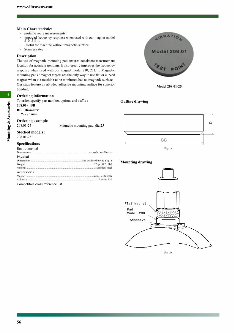
www.vibrasens.com
56
Mou
ntin
g &
Acc
esso
ries
4
Outline drawing
BB
D
Fig 1a
Mounting drawing
Adhesive
PadModel 208
Flat Magnet
Fig 2a
Main Characteristics• portable route measurements• impoved frequency response when used with our magnet model
210, 211, ..• Useful for machine without magnetic surface• Stainless steel
DescriptionThe use of magnetic mounting pad ensures consistent measurement location for accurate trending. It also greatly improves the frequency response when used with our magnet model 210, 211, ... Magnetic mounting pads / magnet targets are the only way to use flat or curved magnet when the machine to be monitored has no magnetic surface.Our pads feature an abraded adhesive mounting surface for superior bonding.
Ordering informationTo order, specify part number, options and suffix :208.01- BB BB : Diameter
25 - 25 mm
Ordering example208.01-25 Magnetic mounting pad, dia 25
Stocked models :208.01-25
SpecificationsEnvironmentalTemperature ................................................................................... depends on adhesive
PhysicalDimensions .......................................................................... See outline drawing Fig 1aWeight ....................................................................................................22 gr ( 0.78 Oz)Material .....................................................................................................Stainless steel
AccessoriesMagnet ................................................................................................ model 21X, 22XAdhesive .......................................................................................................Loctite 330
Competitors cross reference list
Model 208.01-25

www.vibrasens.com
57
Mounting &
Accessories
4Outline drawing
AA
BB
DF
Fig 1a
Model F(mm)
D(mm)
Application
202.01-06-22-2 3.2 3 Model 101, 105
202.01-16-22-2 4.3 5 101, 105 with H7 option
Mounting drawing
PadModel 202
Adhesive
Fig 2a
Cementing - Adhesive pad, Model 202Main Characteristics• Permanent mounting in corrosive environment• For industrial top connector accelerometer• Stainless steel (AISI 316L)
DescriptionCementing pads are used for permanent installations. It eliminates tapping into the structure but provide high frequency capability ap-proaching stud mount. The pad is epoxied in place of the tapped hole; the sensor is then mounted to the pad. Cementing - adhesive pads can provide additional electrical isolation. Adhesive selection is critical for long term reliability. Our cemented pads feature a flat abraded mounting surface for superior bonding and a stud (M5, 10-32 UNF, M6 or 1/4” 28 UNF) for mounting the accelerometer.
Ordering informationTo order, specify part number, options and suffix :202.01- AA - BB - CAA : Sensor thread
05 - M5x0.815 - 10-32 UNF06 - M6x116 - 1/4” 28 UNF
BB : Hexagonal13 - 13 mm19 - 19 mm22 - 22 mm
C : Material2 - AISI 316L
Stocked models :202.01-06-22-2 / 202.01-16-22-2
Ordering example202.01-06-22-2 Adhesive pad, M6, AISI 316
SpecificationsEnvironmentalTemperature ................................................................................... depends on adhesive
PhysicalDimensions .......................................................................... See outline drawing Fig 1aWeight .............................................................................................................................202.01-X6-22-2 ......................................................................................17 gr ( 0.60 Oz)Material ...................................................................................Stainless steel AISI 316L
AccessoriesAdhesive .......................................................................................................Loctite 330
Competitors cross reference listWilcoxon SF8, SF8-2 / CTC online MH130-1A, MH133-1A / AMPO ERD20 (not stainless steel)
Model 202.01-06-22-2

www.vibrasens.com
58
Mou
ntin
g &
Acc
esso
ries
4Outline drawing
AA
BB
DF
Fig 1a
Model F(mm)
D(mm)
Application
204.01-15-17-1 3.2 3 Model 108
204.01-06-22-1 4.3 5 Model 101, 105
204.01-16-11-1 4.3 5 101, 105 with H7 option
Mounting drawing
PadModel 204
Adhesive
Fig 2a
Cementing - Adhesive pad, Model 204Main Characteristics• Permanent mounting• For industrial top connector accelerometer• Stainless steel (AISI 303)
DescriptionCementing pads are used for permanent installations. It eliminates tapping into the structure but provide high frequency capability ap-proaching stud mount. The pad is epoxied in place of the tapped hole; the sensor is then mounted to the pad. Cementing - adhesive pads can provide additional electrical isolation. Adhesive selection is critical for long term reliability. Our cemented pads feature a flat abraded mounting surface for superior bonding and a stud (M5, 10-32 UNF, M6 or 1/4” 28 UNF) for mounting the accelerometer.
Ordering informationTo order, specify part number, options and suffix :204.01- AA - BB - CAA : Sensor thread
05 - M5x0.815 - 10-32 UNF06 - M6x116 - 1/4” 28 UNF
BB : Diameter13 - 13 mm19 - 19 mm22 - 22 mm
C : Material1 - AISI 303
Stocked models :204.01-15-17-1 / 204.01-06-22-1 / 204.01-16-22-1
Ordering example204.01-06-22-1 Adhesive pad, M6, AISI 303
SpecificationsEnvironmentalTemperature ................................................................................... depends on adhesive
PhysicalDimensions .......................................................................... See outline drawing Fig 1aWeight .............................................................................................................................204.01-XX-17-1 ................................................................................. 5.5 gr (~ 0.19 Oz)204.01-XX-22-1 ................................................................................. 9.5 gr (~ 0.33 Oz)Material ..................................................................................... Stainless steel AISI 303
AccessoriesAdhesive .......................................................................................................Loctite 330
Competitors cross reference listWilcoxon SF8, SF8-2 / CTC online MH130-1A, MH133-1A / AMPO ERD20 (not stainless steel)
Model 204.01-06-22

www.vibrasens.com
59
Mounting &
Accessories
4
Outline drawing
AA
BB
D
Fig 1a
Model D(mm)
Application
206.01-06-25-1 10 Model 103
206.01-16-25-1 10 Model 103
Mounting drawing
PadModel 206
Adhesive
Fig 2a
Cementing - Adhesive pad, Model 206Main Characteristics• Permanent mounting• For industrial side connector accelerometer• Stainless steel (AISI 303, AISI 316L)
DescriptionCementing pads are used for permanent installations. It eliminates tapping into the structure but provide high frequency capability ap-proaching stud mount. The pad is epoxied in place of the tapped hole; the sensor is then mounted to the pad. Cementing - adhesive pads can provide additional electrical isolation. Adhesive selection is critical for long term reliability. Our cemented pads feature a flat abraded mounting surface for superior bonding and a tapped hole (M6, M8 or 1/4” 28 UNF) for mounting the accelerometer.
Ordering informationTo order, specify part number, options and suffix :206.01- AA - BB - CAA : Sensor thread
06 - M6x116 - 1/4” 28 UNF
BB : Diameter25 - 25 mm
C : Material1 - AISI 3032 - AISI 316L
Stocked models :206.01-16-25-1 / 206.01-06-25-1
Ordering example206.01-06-25-1 Adhsive pad, M6, AISI 303
SpecificationsEnvironmentalTemperature ................................................................................... depends on adhesive
PhysicalDimensions .......................................................................... See outline drawing Fig 1aWeight ...............................................................................................~XX gr (~ XX Oz)Material .....................................................................................................Stainless steel
Accessories Adhesive .......................................................................................................Loctite 330
Competitors cross reference listWilcoxon SF8, SF8-2 / CTC online MH130-1A, MH133-1A / AMPO ERD20 (not stainless steel)
Model 206.01-06-25

www.vibrasens.com
60
Mou
ntin
g &
Acc
esso
ries
4
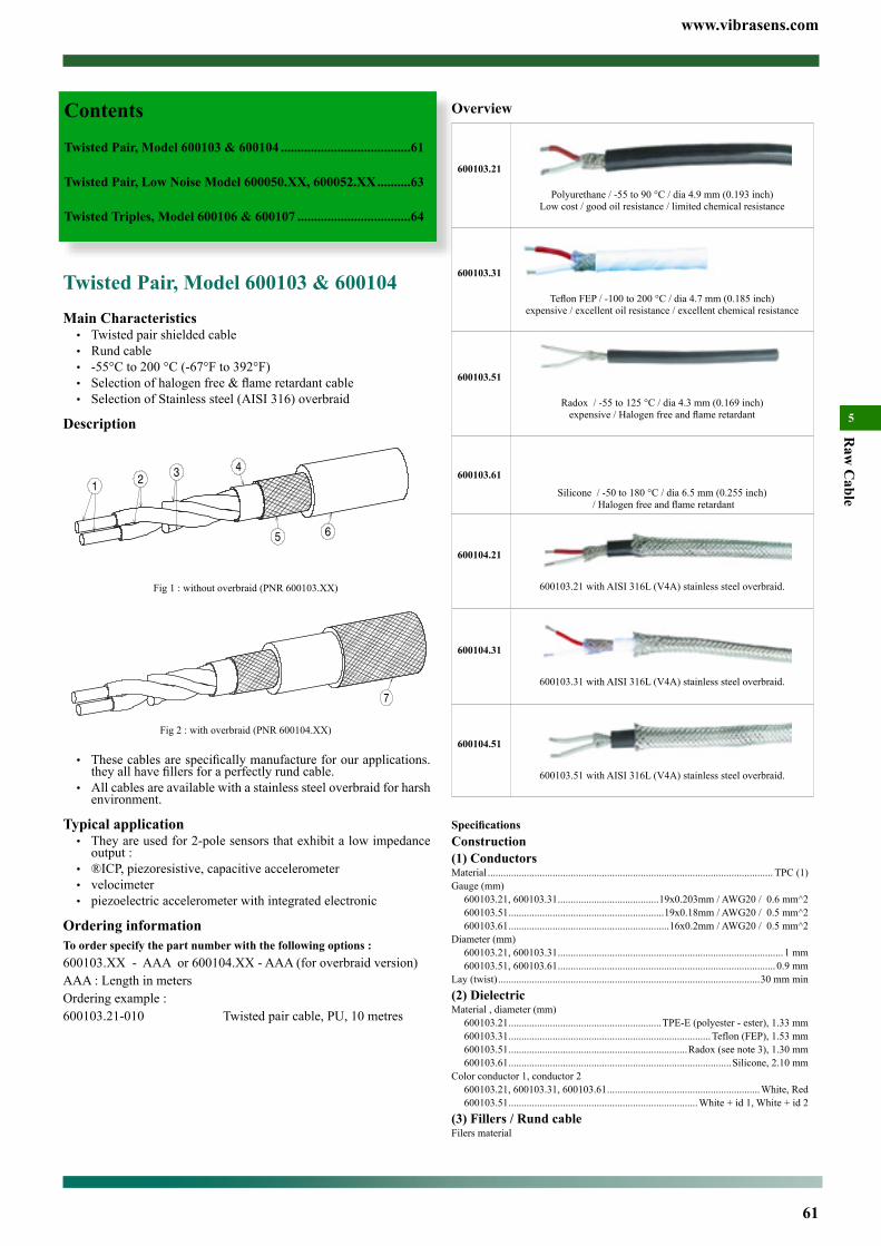
www.vibrasens.com
61
Raw
Cable
5
Overview
600103.21
Polyurethane / -55 to 90 °C / dia 4.9 mm (0.193 inch)Low cost / good oil resistance / limited chemical resistance
600103.31
Teflon FEP / -100 to 200 °C / dia 4.7 mm (0.185 inch)expensive / excellent oil resistance / excellent chemical resistance
600103.51
Radox / -55 to 125 °C / dia 4.3 mm (0.169 inch)expensive / Halogen free and flame retardant
600103.61
Silicone / -50 to 180 °C / dia 6.5 mm (0.255 inch) / Halogen free and flame retardant
600104.21
600103.21 with AISI 316L (V4A) stainless steel overbraid.
600104.31
600103.31 with AISI 316L (V4A) stainless steel overbraid.
600104.51
600103.51 with AISI 316L (V4A) stainless steel overbraid.
SpecificationsConstruction(1) ConductorsMaterial .............................................................................................................. TPC (1)Gauge (mm)
600103.21, 600103.31 .......................................19x0.203mm / AWG20 / 0.6 mm^2600103.51 ............................................................19x0.18mm / AWG20 / 0.5 mm^2600103.61 ..............................................................16x0.2mm / AWG20 / 0.5 mm^2
Diameter (mm)600103.21, 600103.31 ....................................................................................... 1 mm600103.51, 600103.61 .................................................................................... 0.9 mm
Lay (twist) .....................................................................................................30 mm min(2) DielectricMaterial , diameter (mm)
600103.21 ...........................................................TPE-E (polyester - ester), 1.33 mm600103.31 .............................................................................. Teflon (FEP), 1.53 mm600103.51 .....................................................................Radox (see note 3), 1.30 mm600103.61 ......................................................................................Silicone, 2.10 mm
Color conductor 1, conductor 2600103.21, 600103.31, 600103.61 ...........................................................White, Red600103.51 .........................................................................White + id 1, White + id 2
(3) Fillers / Rund cableFilers material
Twisted Pair, Model 600103 & 600104Main Characteristics
• Twisted pair shielded cable• Rund cable• -55°C to 200 °C (-67°F to 392°F)• Selection of halogen free & flame retardant cable• Selection of Stainless steel (AISI 316) overbraid
Description
Fig 1 : without overbraid (PNR 600103.XX)
Fig 2 : with overbraid (PNR 600104.XX)
• These cables are specifically manufacture for our applications. they all have fillers for a perfectly rund cable.
• All cables are available with a stainless steel overbraid for harsh environment.
Typical application• They are used for 2-pole sensors that exhibit a low impedance
output :• ®ICP, piezoresistive, capacitive accelerometer• velocimeter• piezoelectric accelerometer with integrated electronic
Ordering informationTo order specify the part number with the following options :600103.XX - AAA or 600104.XX - AAA (for overbraid version)AAA : Length in metersOrdering example : 600103.21-010 Twisted pair cable, PU, 10 metres
Contents
Twisted Pair, Model 600103 & 600104 .......................................61
Twisted Pair, Low Noise Model 600050.XX, 600052.XX ..........63
Twisted Triples, Model 600106 & 600107 ..................................64
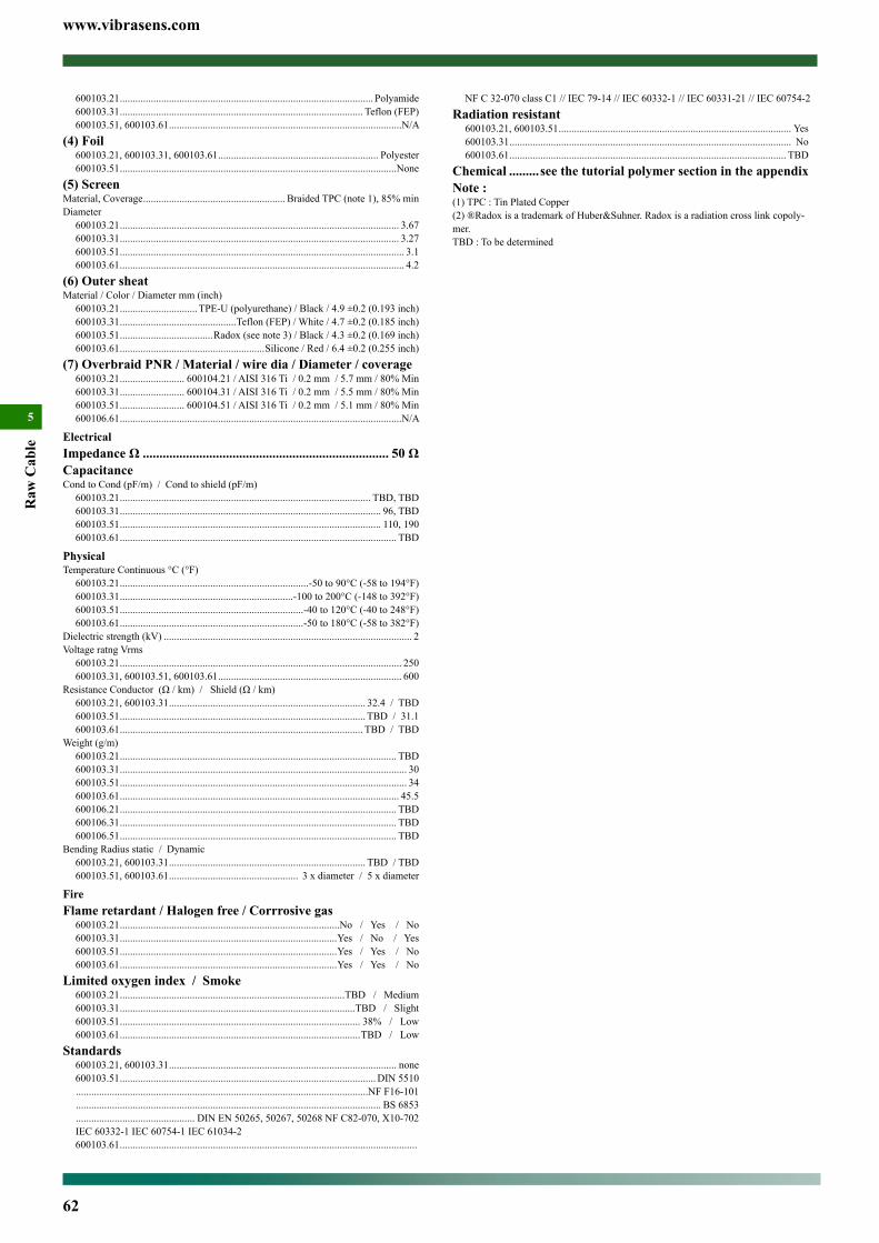
www.vibrasens.com
62
Raw
Cab
le
5
600103.21 .................................................................................................. Polyamide600103.31 .............................................................................................. Teflon (FEP)600103.51, 600103.61 ..........................................................................................N/A
(4) Foil600103.21, 600103.31, 600103.61 .............................................................. Polyester600103.51 ...........................................................................................................None
(5) ScreenMaterial, Coverage ....................................................... Braided TPC (note 1), 85% minDiameter
600103.21 ............................................................................................................ 3.67600103.31 ............................................................................................................ 3.27600103.51 .............................................................................................................. 3.1600103.61 .............................................................................................................. 4.2
(6) Outer sheatMaterial / Color / Diameter mm (inch)
600103.21 .............................. TPE-U (polyurethane) / Black / 4.9 ±0.2 (0.193 inch)600103.31 .............................................Teflon (FEP) / White / 4.7 ±0.2 (0.185 inch)600103.51 ....................................Radox (see note 3) / Black / 4.3 ±0.2 (0.169 inch)600103.61 ........................................................Silicone / Red / 6.4 ±0.2 (0.255 inch)
(7) Overbraid PNR / Material / wire dia / Diameter / coverage600103.21 ......................... 600104.21 / AISI 316 Ti / 0.2 mm / 5.7 mm / 80% Min600103.31 ......................... 600104.31 / AISI 316 Ti / 0.2 mm / 5.5 mm / 80% Min600103.51 ......................... 600104.51 / AISI 316 Ti / 0.2 mm / 5.1 mm / 80% Min600106.61 .............................................................................................................N/A
ElectricalImpedance Ω .......................................................................... 50 ΩCapacitanceCond to Cond (pF/m) / Cond to shield (pF/m)
600103.21 ................................................................................................. TBD, TBD600103.31 ..................................................................................................... 96, TBD600103.51 ..................................................................................................... 110, 190600103.61 ........................................................................................................... TBD
PhysicalTemperature Continuous °C (°F)
600103.21 .........................................................................-50 to 90°C (-58 to 194°F)600103.31 ...................................................................-100 to 200°C (-148 to 392°F)600103.51 .......................................................................-40 to 120°C (-40 to 248°F)600103.61 .......................................................................-50 to 180°C (-58 to 382°F)
Dielectric strength (kV) ................................................................................................ 2Voltage ratng Vrms
600103.21 ............................................................................................................. 250600103.31, 600103.51, 600103.61 ....................................................................... 600
Resistance Conductor (Ω / km) / Shield (Ω / km) 600103.21, 600103.31 ............................................................................ 32.4 / TBD600103.51 ............................................................................................... TBD / 31.1600103.61 .............................................................................................. TBD / TBD
Weight (g/m)600103.21 ........................................................................................................... TBD600103.31 ............................................................................................................... 30600103.51 ............................................................................................................... 34600103.61 ............................................................................................................ 45.5600106.21 ........................................................................................................... TBD600106.31 ........................................................................................................... TBD600106.51 ........................................................................................................... TBD
Bending Radius static / Dynamic600103.21, 600103.31 ............................................................................ TBD / TBD 600103.51, 600103.61 .................................................. 3 x diameter / 5 x diameter
FireFlame retardant / Halogen free / Corrrosive gas
600103.21 .....................................................................................No / Yes / No600103.31 ....................................................................................Yes / No / Yes600103.51 ....................................................................................Yes / Yes / No600103.61 ....................................................................................Yes / Yes / No
Limited oxygen index / Smoke600103.21 .......................................................................................TBD / Medium600103.31 ...........................................................................................TBD / Slight600103.51 ............................................................................................. 38% / Low600103.61 .............................................................................................TBD / Low
Standards600103.21, 600103.31 ........................................................................................ none600103.51 ................................................................................................... DIN 5510 .................................................................................................................NF F16-101 ...................................................................................................................... BS 6853 .............................................. DIN EN 50265, 50267, 50268 NF C82-070, X10-702 IEC 60332-1 IEC 60754-1 IEC 61034-2600103.61 ...................................................................................................................
NF C 32-070 class C1 // IEC 79-14 // IEC 60332-1 // IEC 60331-21 // IEC 60754-2Radiation resistant
600103.21, 600103.51 .......................................................................................... Yes600103.31 ............................................................................................................. No600103.61 ........................................................................................................... TBD
Chemical .........see the tutorial polymer section in the appendixNote :(1) TPC : Tin Plated Copper(2) ®Radox is a trademark of Huber&Suhner. Radox is a radiation cross link copoly-mer.TBD : To be determined
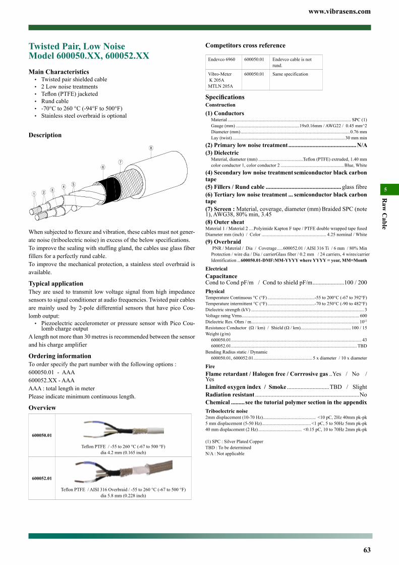
www.vibrasens.com
63
Raw
Cable
5
Competitors cross reference
Endevco 6960 600050.01 Endevco cable is not rund.
Vibro-Meter K 205AMTLN 205A
600050.01 Same specification
SpecificationsConstruction(1) Conductors
Material ......................................................................................................... SPC (1)Gauge (mm) ......................................................19x0.16mm / AWG22 / 0.45 mm^2Diameter (mm) .............................................................................................0.76 mmLay (twist) ................................................................................................30 mm min
(2) Primary low noise treatment .............................................N/A(3) Dielectric
Material, diameter (mm) ......................................Teflon (PTFE) extruded, 1.40 mmcolor conductor 1, color conductor 2 ......................................................Blue, White
(4) Secondary low noise treatment semiconductor black carbon tape(5) Fillers / Rund cable .................................................. glass fibre(6) Tertiary low noise treatment ... semiconductor black carbon tape(7) Screen : Material, coverage, diameter (mm) Braided SPC (note 1), AWG38, 80% min, 3.45(8) Outer sheatMaterial 1 / Material 2 ....Polyimide Kapton F tape / PTFE double wrapped tape fusedDiameter mm (inch) / Color ....................................................... 4.25 nominal / White(9) Overbraid
PNR / Material / Dia / Coverage .....600052.01 / AISI 316 Ti / 6 mm / 80% MinProtection / wire dia / Dia / carrier Glass fiber / 0.2 mm / 24 carriers, 4 wires/carrier Identification ...600050.01-DMF:MM-YYYY where YYYY = year, MM=Month
ElectricalCapacitanceCond to Cond pF/m / Cond to shield pF/m .....................100 / 200PhysicalTemperature Continuous °C (°F) ........................................-55 to 200°C (-67 to 392°F)Temperature intermittent °C (°F) ........................................-70 to 250°C (-90 to 482°F)Dielectric strength (kV) ................................................................................................ 3Voltage ratng Vrms .................................................................................................... 600Dielectric Res. Ohm / m ............................................................................................1012
Resistance Conductor (Ω / km) / Shield (Ω / km)........................................... 100 / 15Weight (g/m)
600050.01 ............................................................................................................... 43600052.01 ........................................................................................................... TBD
Bending Radius static / Dynamic600050.01, 600052.01 .................................................. 5 x diameter / 10 x diameter
FireFlame retardant / Halogen free / Corrrosive gas ..Yes / No / YesLimited oxygen index / Smoke ............................TBD / SlightRadiation resistant .....................................................................NoChemical .........see the tutorial polymer section in the appendixTriboelectric noise2mm displacement (10-70 Hz) ............................................. <10 pC, 2Hz 40mm pk-pk5 mm displacement (5-50 Hz) ..........................................<1 pC, 5 to 50Hz 5mm pk-pk40 mm displacement (2 Hz) ..................................... <0.15 pC, 10 to 70Hz 2mm pk-pk
(1) SPC : Silver Plated CopperTBD : To be determinedN/A : Not applicable
Twisted Pair, Low Noise Model 600050.XX, 600052.XXMain Characteristics
• Twisted pair shielded cable• 2 Low noise treatments• Teflon (PTFE) jacketed• Rund cable• -70°C to 260 °C (-94°F to 500°F)• Stainless steel overbraid is optional
Description
When subjected to flexure and vibration, these cables must not gener-ate noise (triboelectric noise) in excess of the below specifications.To improve the sealing with stuffing gland, the cables use glass fiber fillers for a perfectly rund cable.To improve the mechanical protection, a stainless steel overbraid is available.
Typical applicationThey are used to transmit low voltage signal from high impedance sensors to signal conditioner at audio frequencies. Twisted pair cables are mainly used by 2-pole differential sensors that have pico Cou-lomb output:
• Piezoelectric accelerometer or pressure sensor with Pico Cou-lomb charge output
A length not more than 30 metres is recommended between the sensor and his charge amplifier
Ordering informationTo order specify the part number with the following options :600050.01 - AAA 600052.XX - AAAAAA : total length in meterPlease indicate minimum continuous length.
Overview
600050.01
Teflon PTFE / -55 to 260 °C (-67 to 500 °F) dia 4.2 mm (0.165 inch)
600052.01
Teflon PTFE / AISI 316 Overbraid / -55 to 260 °C (-67 to 500 °F)dia 5.8 mm (0.228 inch)
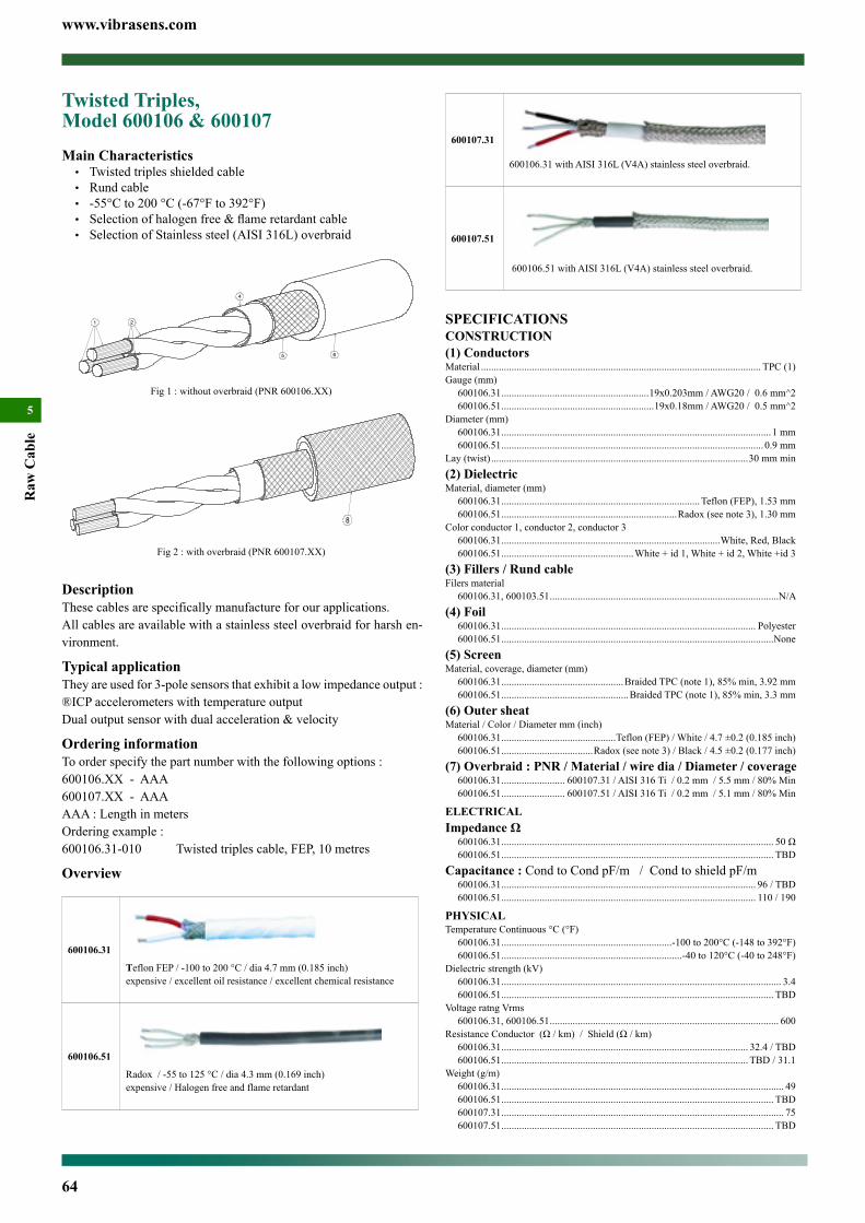
www.vibrasens.com
64
Raw
Cab
le
5
600107.31
600106.31 with AISI 316L (V4A) stainless steel overbraid.
600107.51
600106.51 with AISI 316L (V4A) stainless steel overbraid.
SPECIFICATIONSCONSTRUCTION(1) ConductorsMaterial .............................................................................................................. TPC (1)Gauge (mm)
600106.31 ..........................................................19x0.203mm / AWG20 / 0.6 mm^2600106.51 ............................................................19x0.18mm / AWG20 / 0.5 mm^2
Diameter (mm)600106.31 .......................................................................................................... 1 mm600106.51 ....................................................................................................... 0.9 mm
Lay (twist) .....................................................................................................30 mm min(2) DielectricMaterial, diameter (mm)
600106.31 .............................................................................. Teflon (FEP), 1.53 mm600106.51 .....................................................................Radox (see note 3), 1.30 mm
Color conductor 1, conductor 2, conductor 3600106.31 ......................................................................................White, Red, Black600106.51 ....................................................White + id 1, White + id 2, White +id 3
(3) Fillers / Rund cableFilers material
600106.31, 600103.51 ..........................................................................................N/A(4) Foil
600106.31 .................................................................................................... Polyester600106.51 ...........................................................................................................None
(5) ScreenMaterial, coverage, diameter (mm)
600106.31 ................................................Braided TPC (note 1), 85% min, 3.92 mm600106.51 ..................................................Braided TPC (note 1), 85% min, 3.3 mm
(6) Outer sheatMaterial / Color / Diameter mm (inch)
600106.31 .............................................Teflon (FEP) / White / 4.7 ±0.2 (0.185 inch)600106.51 ....................................Radox (see note 3) / Black / 4.5 ±0.2 (0.177 inch)
(7) Overbraid : PNR / Material / wire dia / Diameter / coverage600106.31 ......................... 600107.31 / AISI 316 Ti / 0.2 mm / 5.5 mm / 80% Min600106.51 ......................... 600107.51 / AISI 316 Ti / 0.2 mm / 5.1 mm / 80% Min
ELECTRICALImpedance Ω
600106.31 ........................................................................................................... 50 Ω600106.51 ........................................................................................................... TBD
Capacitance : Cond to Cond pF/m / Cond to shield pF/m600106.31 .................................................................................................... 96 / TBD600106.51 .................................................................................................... 110 / 190
PHYSICALTemperature Continuous °C (°F)
600106.31 ...................................................................-100 to 200°C (-148 to 392°F)600106.51 .......................................................................-40 to 120°C (-40 to 248°F)
Dielectric strength (kV)600106.31 .............................................................................................................. 3.4600106.51 ........................................................................................................... TBD
Voltage ratng Vrms600106.31, 600106.51 .......................................................................................... 600
Resistance Conductor (Ω / km) / Shield (Ω / km)600106.31 ................................................................................................. 32.4 / TBD600106.51 ................................................................................................. TBD / 31.1
Weight (g/m)600106.31 ............................................................................................................... 49600106.51 ........................................................................................................... TBD600107.31 ............................................................................................................... 75600107.51 ........................................................................................................... TBD
Twisted Triples, Model 600106 & 600107Main Characteristics
• Twisted triples shielded cable• Rund cable• -55°C to 200 °C (-67°F to 392°F)• Selection of halogen free & flame retardant cable• Selection of Stainless steel (AISI 316L) overbraid
Fig 1 : without overbraid (PNR 600106.XX)
Fig 2 : with overbraid (PNR 600107.XX)
DescriptionThese cables are specifically manufacture for our applications. All cables are available with a stainless steel overbraid for harsh en-vironment.
Typical applicationThey are used for 3-pole sensors that exhibit a low impedance output :®ICP accelerometers with temperature outputDual output sensor with dual acceleration & velocity
Ordering informationTo order specify the part number with the following options :600106.XX - AAA 600107.XX - AAAAAA : Length in metersOrdering example : 600106.31-010 Twisted triples cable, FEP, 10 metres
Overview
600106.31
Teflon FEP / -100 to 200 °C / dia 4.7 mm (0.185 inch)expensive / excellent oil resistance / excellent chemical resistance
600106.51
Radox / -55 to 125 °C / dia 4.3 mm (0.169 inch)expensive / Halogen free and flame retardant

www.vibrasens.com
65
Raw
Cab
le
5
Bending Radius static / Dynamic600106.31 ................................................................................................ TBD / TBD600106.51 ...................................................................... 3 x diameter / 5 x diameter
FireFlame retardant / Halogen free / Corrrosive gas
600106.31 ....................................................................................Yes / No / Yes600106.51 ....................................................................................Yes / Yes / No
Limited oxygen index / Smoke600106.31 ...........................................................................................TBD / Slight600106.51 ............................................................................................. 38% / Low
Standards600106.31 ........................................................................................................... none600106.51 ................................................................................................... DIN 5510 .................................................................................................................NF F16-101 ...................................................................................................................... BS 6853 .............................................. DIN EN 50265, 50267, 50268 NF C82-070, X10-702 ....................................................................IEC 60332-1 IEC 60754-1 IEC 61034-2
Radiation resistant600106.31 ............................................................................................................. No600106.51 ............................................................................................................. Yes
Chemical .........see the tutorial polymer section in the appendix
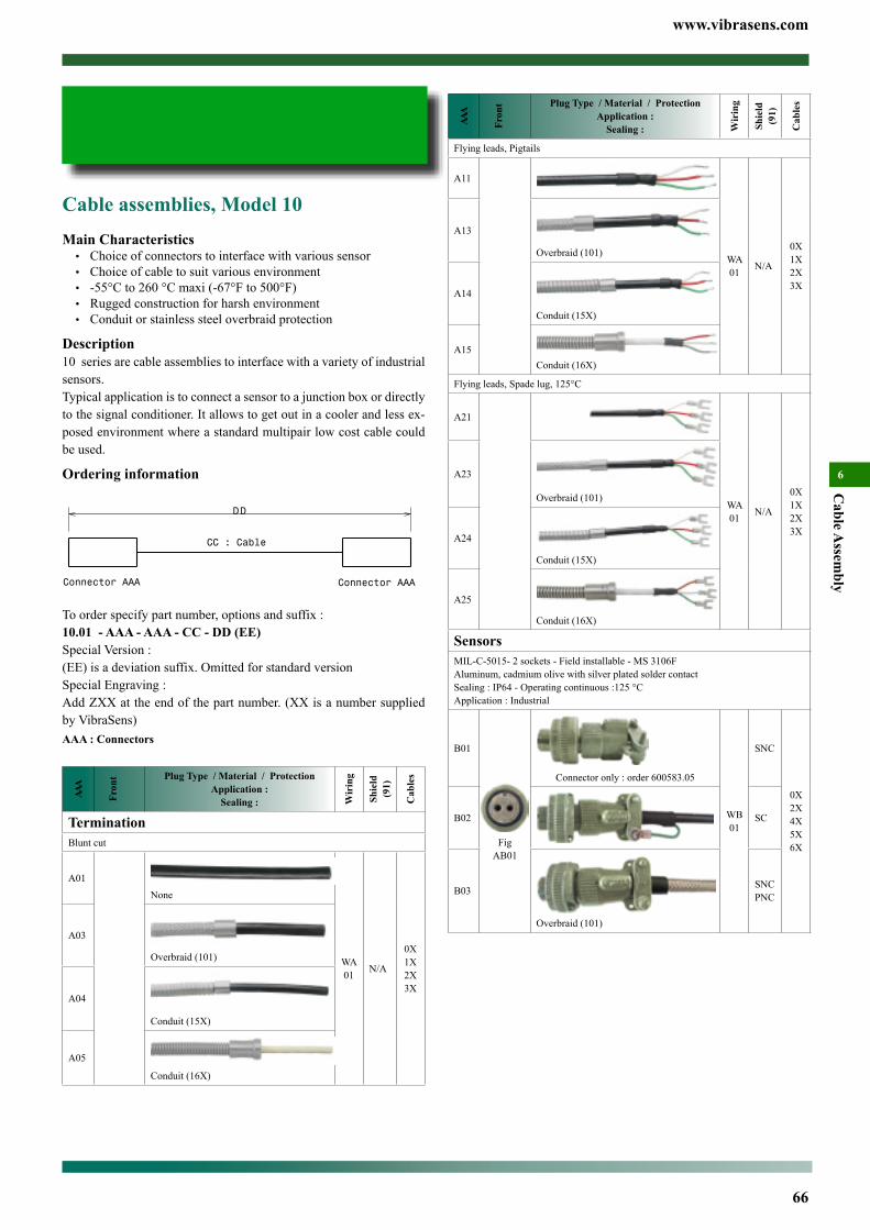
www.vibrasens.com
66
Cable A
ssembly
6AA
A
Fron
t Plug Type / Material / ProtectionApplication :
Sealing : Wir
ing
Shie
ld
(91)
Cab
les
Flying leads, Pigtails
A11
WA01 N/A
0X1X2X3X
A13
Overbraid (101)
A14
Conduit (15X)
A15Conduit (16X)
Flying leads, Spade lug, 125°C
A21
WA01 N/A
0X1X2X3X
A23
Overbraid (101)
A24
Conduit (15X)
A25
Conduit (16X)
SensorsMIL-C-5015- 2 sockets - Field installable - MS 3106FAluminum, cadmium olive with silver plated solder contactSealing : IP64 - Operating continuous :125 °CApplication : Industrial
B01
Fig AB01
Connector only : order 600583.05
WB01
SNC
0X2X4X5X6X
B02 SC
B03
Overbraid (101)
SNCPNC
Cable assemblies, Model 10Main Characteristics• Choice of connectors to interface with various sensor• Choice of cable to suit various environment• -55°C to 260 °C maxi (-67°F to 500°F)• Rugged construction for harsh environment• Conduit or stainless steel overbraid protection
Description10 series are cable assemblies to interface with a variety of industrial sensors.Typical application is to connect a sensor to a junction box or directly to the signal conditioner. It allows to get out in a cooler and less ex-posed environment where a standard multipair low cost cable could be used.
Ordering information
To order specify part number, options and suffix :10.01 - AAA - AAA - CC - DD (EE)Special Version :(EE) is a deviation suffix. Omitted for standard versionSpecial Engraving :Add ZXX at the end of the part number. (XX is a number supplied by VibraSens)AAA : Connectors
AAA
Fron
t Plug Type / Material / ProtectionApplication :
Sealing : Wir
ing
Shie
ld
(91)
Cab
les
TerminationBlunt cut
A01None
WA01 N/A
0X1X2X3X
A03
Overbraid (101)
A04
Conduit (15X)
A05
Conduit (16X)
Contents
Cable assemblies, Model 10 .........................................................66
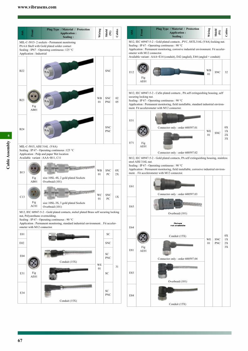
www.vibrasens.com
67
Cab
le A
ssem
bly
6AA
A
Fron
t Plug Type / Material / ProtectionApplication :
Sealing : Wir
ing
Shie
ld
(91)
Cab
les
M12, IEC 60947-5-2 - Gold plated contacts , PVC, SSTL316L (V4A) locking nut.Sealing : IP 67 - Operating continuous : 90 °CApplication : Permanent monitoring, corrosive industrial environment. Fit acceler-ometer with M12 connector.Available variant : AAA=E14 (conduit), E42 (angled), E44 (angled + conduit)
E12
Fig AE01
WB01 SNC 32
M12, IEC 60947-5-2 - CuSn plated contacts , PA self extinguishing housing, self securing locking nut.Sealing : IP 67 - Operating continuous : 90 °CApplication : Permanent monitoring, field installable, standard industrial environ-ment. Fit accelerometer with M12 connector.
E51
Fig AE01
Connector only : order 600597.01WE01 SNC
0X1X2X3X
E71
Connector only : order 600597.02
M12, IEC 60947-5-2 - Gold plated contacts, PA self extinguishing housing, stainless steel AISI 316L nut.Sealing : IP 67 - Operating continuous : 90 °CApplication : Permanent monitoring, field installable, corrosive industrial environ-ment. . Fit accelerometer with M12 connector.
E61
Fig AE01
Connector only : order 600597.03
WE01
SNCPNC
0X1X2X3X
E63
Overbraid (101)
E64
Conduit (15X)
E81
Connector only : order 600597.04
E83
Overbraid (101)
E84
Conduit (15X)
AAA
Fron
t Plug Type / Material / ProtectionApplication :
Sealing : Wir
ing
Shie
ld
(91)
Cab
les
MIL-C-5015- 2 sockets - Permanent monitoringPA 6.6 Shell with Gold plated solder contactSealing : IP67 - Operating continuous :125 °CApplication : Industrial
B22
Fig AB01
WB01
SNC
0205B23 SNC
PNC
B24 SNCPNC
MIL-C-5015, AISI 316L (V4A)Sealing : IP 67 - Operating continuous :125 °CApplication : Pulp and paper Wet locationAvailable variant : AAA=B11, C11
B13
Fig AB01
size 10SL-4S, 2 gold plated SocketsOverbraid (101)
WB01
SNCPC
0X2X
C13
Fig AC01
size 10SL-3S, 3 gold plated SocketsOverbraid (101)
WC01
SNCPC 1X
M12, IEC 60947-5-2 - Gold plated contacts, nickel plated Brass self securing locking nut, Polyurethane overmolding.Sealing : IP 67 - Operating continuous : 90 °CApplication : Permanent monitoring, standard industrial environment. . Fit acceler-ometer with M12 connector.
E01
Fig AE01
WE01
SC
31
E02 SNC
E04
Conduit (15X)
SCPNC
E31 SC
E34
Conduit (15X)
SCPNC
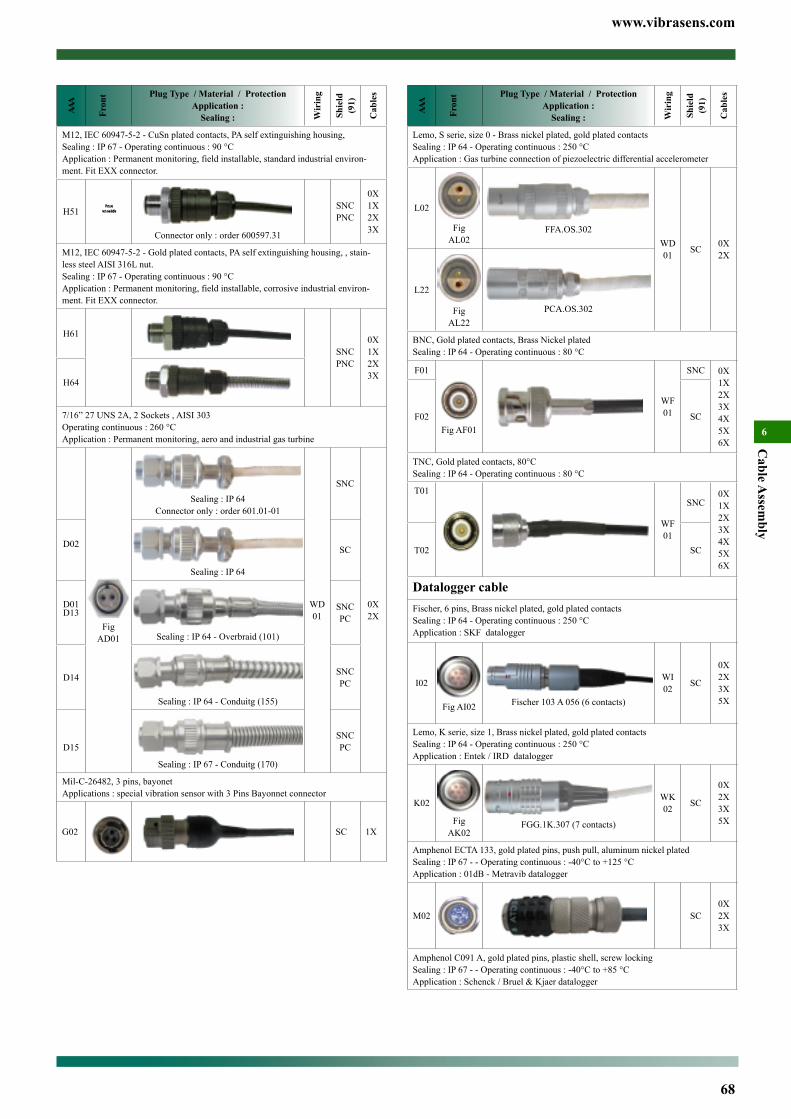
www.vibrasens.com
68
Cable A
ssembly
6AA
A
Fron
t Plug Type / Material / ProtectionApplication :
Sealing : Wir
ing
Shie
ld
(91)
Cab
les
Lemo, S serie, size 0 - Brass nickel plated, gold plated contactsSealing : IP 64 - Operating continuous : 250 °CApplication : Gas turbine connection of piezoelectric differential accelerometer
L02
Fig AL02
FFA.OS.302WD01 SC 0X
2X
L22
Fig AL22
PCA.OS.302
BNC, Gold plated contacts, Brass Nickel platedSealing : IP 64 - Operating continuous : 80 °C
F01
Fig AF01
WF01
SNC 0X1X2X3X4X5X6X
F02 SC
TNC, Gold plated contacts, 80°CSealing : IP 64 - Operating continuous : 80 °C
T01
WF01
SNC0X1X2X3X4X5X6X
T02 SC
Datalogger cableFischer, 6 pins, Brass nickel plated, gold plated contactsSealing : IP 64 - Operating continuous : 250 °CApplication : SKF datalogger
I02
Fig AI02 Fischer 103 A 056 (6 contacts)
WI02 SC
0X2X3X5X
Lemo, K serie, size 1, Brass nickel plated, gold plated contactsSealing : IP 64 - Operating continuous : 250 °CApplication : Entek / IRD datalogger
K02
Fig AK02
FGG.1K.307 (7 contacts)
WK02 SC
0X2X3X5X
Amphenol ECTA 133, gold plated pins, push pull, aluminum nickel platedSealing : IP 67 - - Operating continuous : -40°C to +125 °CApplication : 01dB - Metravib datalogger
M02 SC0X2X3X
Amphenol C091 A, gold plated pins, plastic shell, screw lockingSealing : IP 67 - - Operating continuous : -40°C to +85 °CApplication : Schenck / Bruel & Kjaer datalogger
AAA
Fron
t Plug Type / Material / ProtectionApplication :
Sealing : Wir
ing
Shie
ld
(91)
Cab
les
M12, IEC 60947-5-2 - CuSn plated contacts, PA self extinguishing housing, Sealing : IP 67 - Operating continuous : 90 °CApplication : Permanent monitoring, field installable, standard industrial environ-ment. Fit EXX connector.
H51
Connector only : order 600597.31
SNCPNC
0X1X2X3X
M12, IEC 60947-5-2 - Gold plated contacts, PA self extinguishing housing, , stain-less steel AISI 316L nut.Sealing : IP 67 - Operating continuous : 90 °CApplication : Permanent monitoring, field installable, corrosive industrial environ-ment. Fit EXX connector.
H61
SNCPNC
0X1X2X3X
H64
7/16” 27 UNS 2A, 2 Sockets , AISI 303Operating continuous : 260 °CApplication : Permanent monitoring, aero and industrial gas turbine
D01
Fig AD01
Sealing : IP 64Connector only : order 601.01-01
WD01
SNC
0X2X
D02
Sealing : IP 64
SC
D13
Sealing : IP 64 - Overbraid (101)
SNCPC
D14
Sealing : IP 64 - Conduitg (155)
SNCPC
D15 Sealing : IP 67 - Conduitg (170)
SNCPC
Mil-C-26482, 3 pins, bayonetApplications : special vibration sensor with 3 Pins Bayonnet connector
G02 SC 1X
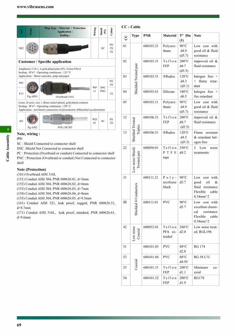
www.vibrasens.com
69
Cab
le A
ssem
bly
6
CC : Cable
CC Type PNR Material T° Dia
(1)Note
01
Shie
lded
Tw
iste
d pa
ir
600103.21 Polyure-thane
90°C d4.9 (d5.7)
Low cost with good oil & fluid resistance
02 600103.31 T e f l o n FEP
200°C d4.7 (d5.5)
improved oil & fluid resistance
03 600103.51 ®Radox 120°C d4.3 (d5.1)
halogen free + + flame retar-dant
04 600103.61 Silicone 180°C d6.5
halogen free + fire retardant
05 600103.11 Polyure-thane
90°C d4.9 (d5.7)
Low cost with good oil & fluid resistance
12
Shie
lded
Tw
iste
d Tr
iple
s
600106.31 T e f l o n FEP
200°C d4.7 (d5.5)
improved oil & fluid resistance
13 600106.51 ®Radox 120°C d4.5 (d5.3)
Flame resistant & retardant hal-ogen free
22
Low
noi
se S
hiel
d.
Twis
ted
pair
600050.01 T e f l o n P T F E tape
250°Cd4.2
2 Low noise treatments
31
Shie
lded
4 C
ondu
ctor
s
600111.21 P o l y -urethane black
90°C d5.7
Low cost with good oil & fluid resistance Flexible cable 0.34mm^2
32 600111.01 PVC 90°C d5.7
Low cost with excellent chemi-cal resistance Flexible cable 0.34mm^2
42
Low
noi
se
Coa
xial
600052.01 T e f l o n PFA ex-truded
260°Cd2.0
Low noise treat-ed. RGL196
51
Coa
xial
600101.03 PVC 80°Cd2.8
RG 174
52 600101.04 PVC 80°Cd4.95
RG 58 C/U
53 600101.31 T e f l o n FEP
200°Cd1.1
Miniature co-axial
54 600101.32 T e f l o n FEP
200°C d1.9
RG178
AAA
Fron
t Plug Type / Material / ProtectionApplication :
Sealing : Wir
ing
Shie
ld
(91)
Cab
les
N02 SC0X2X3X
Customer / Specific application
Amphenol, C16-1, 4 gold plated pins (03), Nylon PA6.6Sealing : IP 67 - Operating continuous : 125 °CApplication : Metso sensodec, pulp and paper
P03
Fig AP01 Overbraid (101)
WP11
SNCPNC
0X2X
P13 1X
Lemo, B serie, size 1, Brass nickel plated, gold plated contactsSealing : IP 67 - Operating continuous : 250 °CApplication : test bench connection of piezoelectric differential accelerometer
J02
fig AJ02 FGG.1B.302
WD01 SC 0X
2X
Note, wiring :(91)
SC : Shield Connected to connector shellSNC :Shield Not Connected to connector shellPC : Protection (Overbraid or conduit) Connected to connector shellPNC : Protection (Overbraid or conduit) Not Connected to connector shell
Note (Protection)(101) Overbraid AISI 316L(151) Conduit AISI 304, PNR 600626.01, d=5mm(152) Conduit AISI 304, PNR 600626.02, d=6mm(153) Conduit AISI 304, PNR 600626.03, d=7mm(154) Conduit AISI 304, PNR 600626.04, d=8mm(155) Conduit AISI 304, PNR 600626.05, d=9.5mm(161) Conduit AISI 321, leak proof, rugged, PNR 600626.51, d=8.7mm(171) Conduit AISI 316L, leak proof, standard, PNR 600626.61, d=9.6mm
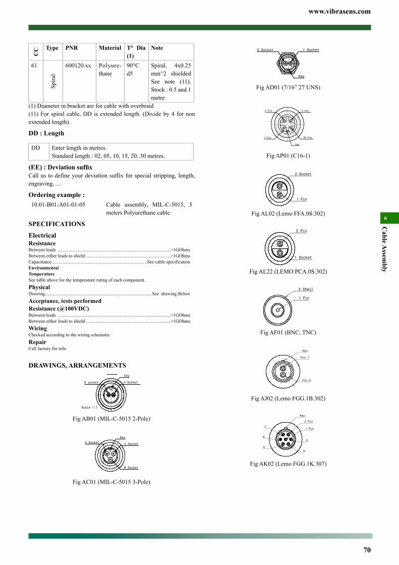
www.vibrasens.com
70
Cable A
ssembly
6
Fig AD01 (7/16” 27 UNS)
Fig AP01 (C16-1)
Fig AL02 (Lemo FFA.0S.302)
Fig AL22 (LEMO PCA.0S.302)
Fig AF01 (BNC, TNC)
Fig AJ02 (Lemo FGG.1B.302)
Fig AK02 (Lemo FGG.1K.307)
CC Type PNR Material T° Dia
(1)Note
61
Spira
l
600120.xx Polyure-thane
90°Cd5
Spiral, 4x0.25 mm^2 shielded See note (11). Stock : 0.5 and 1 metre
(1) Diameter in bracket are for cable with overbraid(11) For spiral cable, DD is extended length. (Divide by 4 for non extended length).
DD : Length
DD Enter length in metres.Standard length : 02, 05, 10, 15, 20, 30 metres.
(EE) : Deviation suffixCall us to define your deviation suffix for special stripping, length, engraving, ....
Ordering example :10.01-B01-A01-01-05 Cable assembly, MIL-C-5015, 5
meters Polyurethane cable
SPECIFICATIONS
ElectricalResistanceBetween leads ................................................................................................>1GOhmsBetween either leads to shield ........................................................................>1GOhmsCapacitance .................................................................................See cable specificationEnvironmentalTemperatureSee table above for the temperature rating of each component.PhysicalDrawing ...........................................................................................See drawing BelowAcceptance, tests performedResistance (@100VDC)Between leads ................................................................................................>1GOhmsBetween either leads to shield ........................................................................>1GOhmsWiringChecked according to the wiring schematicRepairCall factory for info
DRAWINGS, ARRANGEMENTS
Fig AB01 (MIL-C-5015 2-Pole)
Fig AC01 (MIL-C-5015 3-Pole)
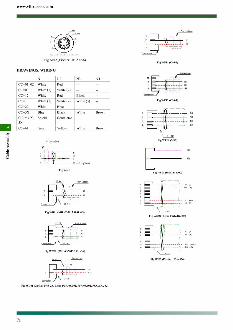
www.vibrasens.com
71
Cab
le A
ssem
bly
6
Fig WP11 (C16-1)
Fig WP12 (C16-1)
Fig WE01 (M12)
Fig WF01 (BNC & TNC)
Fig WK02 (Lemo FGG.1K.307)
6
5 N1 (GND)
4
3
2
If SC
1
N4 (Z)
N2 (X)
N3 (Y)
Fig WI02 (Fischer 103 A 056)
Key
1 Pin
2
35
Fig AI02 (Fischer S 103 A056)
4
6
Fig AI02 (Fischer 103 A 056)
DRAWINGS, WIRING
N1 N2 N3 N4CC=01, 02 White Red -- --CC=03 White (1) White (2) -- --CC=12 White Red Black --CC=13 White (1) White (2) White (3) --CC=22 White Blue -- --CC=3X Blue Black White BrownC C = 4 X , 5X
Shield Conductor
CC=61 Green Yellow White Brown
Fig WA01
Fig WB01 (MIL-C-5015 10SL-4S)
Fig WC01 (MIL-C-5015 10SL-3S)
Fig WD01 (7/16 27 UNS 2A, Lemo PCA.0S.302, FFA.0S.302, FGG.1K.302)
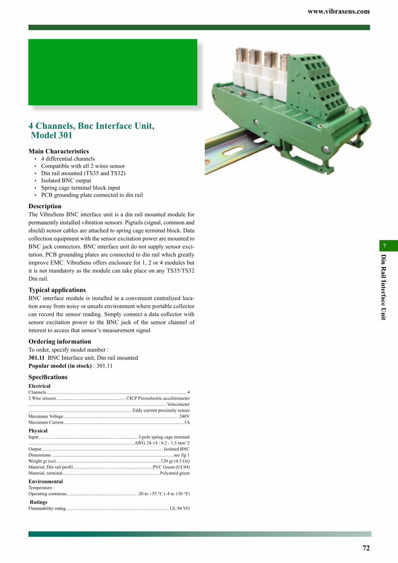
www.vibrasens.com
72
Din R
ail Interface Unit
7
4 Channels, Bnc Interface Unit, Model 301Main Characteristics• 4differentialchannels• Compatiblewithall2wiressensor• Dinrailmounted(TS35andTS32)• IsolatedBNCoutput• Springcageterminalblockinput• PCBgroundingplateconnectedtodinrail
DescriptionTheVibraSensBNCinterfaceunitisadinrailmountedmoduleforpermanentlyinstalledvibrationsensors.Pigtails(signal,commonandshield)sensorcablesareattachedtospringcageterminalblock.DatacollectionequipmentwiththesensorexcitationpoweraremountedtoBNCjackconnectors.BNCinterfaceunitdonotsupplysensorexci-tation.PCBgroundingplatesareconnectedtodinrailwhichgreatlyimproveEMC.VibraSensoffersenclosurefor1,2or4modulesbutitisnotmandatoryasthemodulecantakeplaceonanyTS35/TS32Dinrail.
Typical applicationsBNCinterfacemoduleisinstalledinaconvenientcentralizedloca-tionawayfromnoisyorunsafeenvironmentwhereportablecollectorcanrecordthesensorreading.Simplyconnectadatacollectorwithsensor excitation power to theBNC jack of the sensor channel ofinteresttoaccessthatsensor’smeasurementsignal
Ordering informationToorder,specifymodelnumber:301.11BNCInterfaceunit,DinrailmountedPopular model (in stock):301.11
SpecificationsElectricalChannels........................................................................................................................ 42Wiresensors...........................................................©ICPPiezoelectricaccelerometer......................................................................................................................Velocimeter........................................................................................ EddycurrentproximitysensorMaximumVoltage.................................................................................................. 240VMaximumCurrent.......................................................................................................5A
PhysicalInput.................................................................................... 3-polespringcageterminal..........................................................................................AWG24-14/0.2-1.5mm^2Output....................................................................................................... IsolatedBNCDimensions........................................................................................................seefig1Weightgr(oz).........................................................................................120gr(4.3Oz)Material,Dinrailprofil....................................................................PVCGreen(UL94)Material,terminal...................................................................................Polyamidgreen
EnvironmentalTemperature:Operatingcontinous........................................................... -20to+55°C(-4to130°F)
RatingsFlammabilityrating....................................................................................... UL94VO
Contents
4 Channels, Bnc Interface Unit, Model 301 ...............................72
12 Channels, Bnc Interface Unit, Model 300 .............................74
11 Channels, Switch Interface Unit, Model 302 ........................75
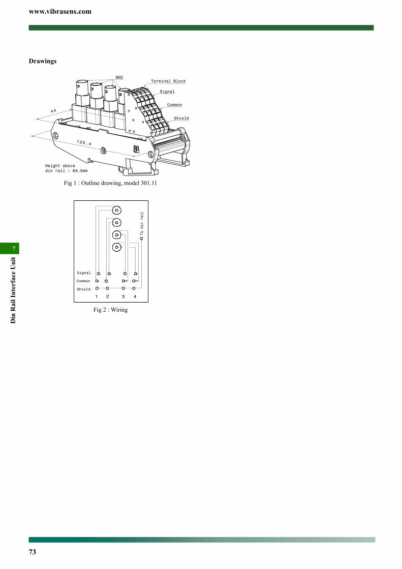
www.vibrasens.com
73
Din
Rai
l Int
erfa
ce U
nit
7
Drawings
Fig1:Outlinedrawing,model301.11
Fig2:Wiring

www.vibrasens.com
74
Din R
ail Interface Unit
7
model 300.11
Drawings
125.4
109.5
Height abovedin rail : 80
Terminal Block
Shield
Common
Signal
BNC
Fig 1 : Outline drawing, model 300.11
125.4Height abovedin rail : 80 mm
109.5
Fig 2 : Outline drawing, model 300.01
12 Channels, Bnc Interface Unit, Model 300Main Characteristics• 12differentialchannels• Compatiblewithall2wiressensor• Dinrailmounted(TS35andTS32)• IsolatedBNCoutput• Springcageterminalblockinput• PCBgroundingplateconnectedtodinrail
DescriptionTheVibraSensBNCinterfaceunitisadinrailmountedmoduleforpermanentlyinstalledvibrationsensors.Pigtails(signal,commonandshield)sensorcablesareattachedtospringcageterminalblock.DatacollectionequipmentwiththesensorexcitationpoweraremountedtoBNCjackconnectors.BNCinterfaceunitdonotsupplysensorexci-tation.PCBgroundingplatesareconnectedtodinrailwhichgreatlyimproveEMC.VibraSensoffersenclosurefor1,2or4modulesbutitisnotmandatoryasthemodulecantakeplaceonanyTS35/TS32Dinrail.
Typical applicationsBNCinterfacemoduleisinstalledinaconvenientcentralizedloca-tionawayfromnoisyorunsafeenvironmentwhereportablecollectorcanrecordthesensorreading.Simplyconnectadatacollectorwithsensor excitation power to theBNC jack of the sensor channel ofinteresttoaccessthatsensor’smeasurementsignal
Ordering informationToorder,specifymodelnumber:300.01BNCinterfaceunit,Dinrailmounted300.11BNCinterfaceunit,Dinrailmounted,rightanglePopular model (in stock):300.11and300.01
SpecificationsElectricalChannels...................................................................................................................... 122Wiresensors...........................................................©ICPPiezoelectricaccelerometer......................................................................................................................Velocimeter........................................................................................ EddycurrentproximitysensorMaximumVoltage.................................................................................................. 240VMaximumCurrent.......................................................................................................5A
PhysicalInput.................................................................................... 3-polespringcageterminal..........................................................................................AWG24-14/0.2-1.5mm^2Output....................................................................................................... IsolatedBNCDimensions........................................................................................................seefig1Weightgr(oz).....................................................................................XXXgr(XXOz)Material,Dinrailprofil....................................................................PVCGreen(UL94)Material,terminal...................................................................................Polyamidgreen
EnvironmentalTemperature:Operatingcontinous........................................................... -20to+55°C(-4to130°F)
RatingsFlammabilityrating....................................................................................... UL94VO
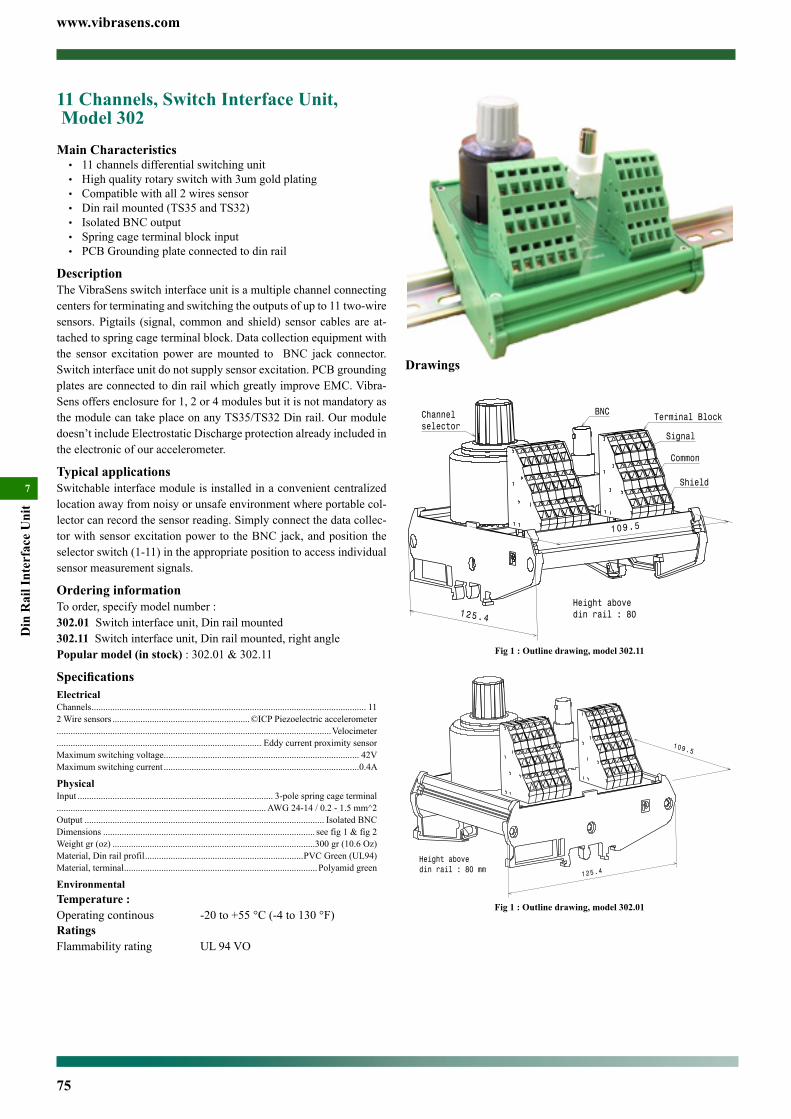
www.vibrasens.com
75
Din
Rai
l Int
erfa
ce U
nit
77
Drawings
Fig 1 : Outline drawing, model 302.11
Fig 1 : Outline drawing, model 302.01
11 Channels, Switch Interface Unit, Model 302Main Characteristics• 11channelsdifferentialswitchingunit• Highqualityrotaryswitchwith3umgoldplating• Compatiblewithall2wiressensor• Dinrailmounted(TS35andTS32)• IsolatedBNCoutput• Springcageterminalblockinput• PCBGroundingplateconnectedtodinrail
DescriptionTheVibraSensswitchinterfaceunitisamultiplechannelconnectingcentersforterminatingandswitchingtheoutputsofupto11two-wiresensors. Pigtails (signal, common and shield) sensor cables are at-tachedtospringcageterminalblock.Datacollectionequipmentwiththe sensor excitation power aremounted to BNC jack connector.Switchinterfaceunitdonotsupplysensorexcitation.PCBgroundingplatesareconnectedtodinrailwhichgreatlyimproveEMC.Vibra-Sensoffersenclosurefor1,2or4modulesbutitisnotmandatoryasthemodulecantakeplaceonanyTS35/TS32Dinrail.Ourmoduledoesn’tincludeElectrostaticDischargeprotectionalreadyincludedintheelectronicofouraccelerometer.
Typical applicationsSwitchableinterfacemoduleisinstalledinaconvenientcentralizedlocationawayfromnoisyorunsafeenvironmentwhereportablecol-lectorcanrecordthesensorreading.Simplyconnectthedatacollec-torwithsensorexcitationpower to theBNCjack,andposition theselectorswitch(1-11)intheappropriatepositiontoaccessindividualsensormeasurementsignals.
Ordering informationToorder,specifymodelnumber:302.01Switchinterfaceunit,Dinrailmounted302.11Switchinterfaceunit,Dinrailmounted,rightanglePopular model (in stock):302.01&302.11
SpecificationsElectricalChannels...................................................................................................................... 112Wiresensors...........................................................©ICPPiezoelectricaccelerometer......................................................................................................................Velocimeter........................................................................................ EddycurrentproximitysensorMaximumswitchingvoltage.................................................................................... 42VMaximumswitchingcurrent....................................................................................0.4A
PhysicalInput.................................................................................... 3-polespringcageterminal..........................................................................................AWG24-14/0.2-1.5mm^2Output....................................................................................................... IsolatedBNCDimensions........................................................................................... seefig1&fig2Weightgr(oz).......................................................................................300gr(10.6Oz)Material,Dinrailprofil....................................................................PVCGreen(UL94)Material,terminal...................................................................................Polyamidgreen
EnvironmentalTemperature :Operatingcontinous -20to+55°C(-4to130°F)RatingsFlammabilityrating UL94VO

www.vibrasens.com
76
Din R
ail Interface Unit
7
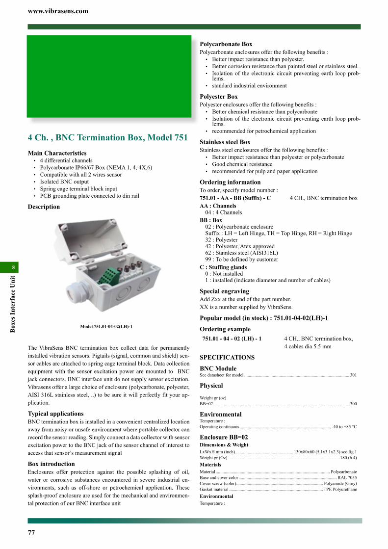
www.vibrasens.com
77
Box
es In
terf
ace
Uni
t
8
4 Ch. , BNC Termination Box, Model 751Main Characteristics• 4differentialchannels• PolycarbonateIP66/67Box(NEMA1,4,4X,6)• Compatiblewithall2wiressensor• IsolatedBNCoutput• Springcageterminalblockinput• PCBgroundingplateconnectedtodinrail
Description
TheVibraSens BNC termination box collect data for permanentlyinstalledvibrationsensors.Pigtails(signal,commonandshield)sen-sorcablesareattachedtospringcageterminalblock.Datacollectionequipmentwith the sensor excitation power aremounted to BNCjackconnectors.BNCinterfaceunitdonotsupplysensorexcitation.Vibrasensofferalargechoiceofenclosure(polycarbonate,polyester,AISI316Lstainlesssteel,..)tobesureitwillperfectlyfityourap-plication.
Typical applicationsBNCterminationboxisinstalledinaconvenientcentralizedlocationawayfromnoisyorunsafeenvironmentwhereportablecollectorcanrecordthesensorreading.SimplyconnectadatacollectorwithsensorexcitationpowertotheBNCjackofthesensorchannelofinteresttoaccessthatsensor’smeasurementsignal
Box introductionEnclosures offer protection against the possible splashing of oil,water or corrosive substances encountered in severe industrial en-vironments, such as off-shore or petrochemical application. Thesesplash-proofenclosureareusedforthemechanicalandenvironmen-talprotectionofourBNCinterfaceunit
Fig 1 : Outline drawing, model 751.01-XX-02 (LH)
Model 751.01-04-02(LH)-1
Polycarbonate BoxPolycarbonateenclosuresofferthefollowingbenefits:• Betterimpactresistancethanpolyester.• Bettercorrosionresistancethanpaintedsteelorstainlesssteel.• Isolationof the electronic circuit preventing earth loopprob-lems.
• standardindustrialenvironment
Polyester BoxPolyesterenclosuresofferthefollowingbenefits:• Betterchemicalresistancethanpolycarbonte• Isolationof the electronic circuit preventing earth loopprob-lems.
• recommendedforpetrochemicalapplication
Stainless steel BoxStainlesssteelenclosuresofferthefollowingbenefits:• Betterimpactresistancethanpolyesterorpolycarbonate• Goodchemicalresistance• recommendedforpulpandpaperapplication
Ordering informationToorder,specifymodelnumber:751.01 - AA - BB (Suffix) - C 4CH., BNCterminationboxAA : Channels04:4Channels
BB : Box02:PolycarbonateenclosureSuffix:LH=LeftHinge,TH=TopHinge,RH=RightHinge32:Polyester42:Polyester,Atexapproved62:Stainlesssteel(AISI316L)99:Tobedefinedbycustomer
C : Stuffing glands0:Notinstalled1:installed(indicatediameterandnumberofcables)
Special engravingAddZxxattheendofthepartnumber.XXisanumbersuppliedbyVibraSens.
Popular model (in stock) : 751.01-04-02(LH)-1
Ordering example751.01 - 04 - 02 (LH) - 1 4CH.,BNCterminationbox,
4cablesdia5.5mm
SPECIFICATIONS
BNC ModuleSeedatasheetformodel............................................................................................ 301
Physical
Weightgr(oz)BB=02....................................................................................................................... 300
EnvironmentalTemperature:Operatingcontinuous................................................................................ -40to+85°C
Enclosure BB=02Dimensions & WeightLxWxHmm(inch)................................................... 130x80x60(5.1x3.1x2.3)seefig1Weightgr(Oz)..................................................................................................180(6.4)MaterialsMaterial.................................................................................................... PolycarbonateBaseandcovercolor...................................................................................... RAL7035Coverscrew(color)............................................................................ Polyamide(Grey)Gasketmaterial..................................................................................TPEPolyurethaneEnvironmentalTemperature:
Contents
4 Ch. , BNC Termination Box, Model 751 .................................77
8 Ch. , BNC Termination Box, Model 750 .................................79
11/12 Ch. , Switch/BNC Termination Box, Model 749 ..............81
22/24 Ch., Switch/BNC Termination Box, Model 748...............83
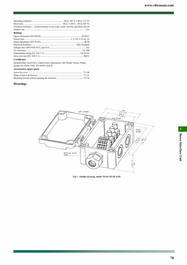
www.vibrasens.com
78
Boxes Interface U
nit
8
Operatingcontinous......................................................... -40to+80°C(-40to175°F)Shortterm....................................................................... -40to+120°C(-40to250°F)Chemicalresistance... Goodresistancetoseawater,acids,solvents,gasolinesandoilOutdooruse............................................................................................................... YesRatingsIngressProtection(EN60529)...........................................................................IP66/67NemaClass....................................................................................1,4,4X,6(12&13)ImpactResistance(EN50102).............................................................................. IK08Electricalinsultaion................................................................................. fullyinsulatedHalogenfree(DIN/VDE0472,part815)................................................................. YesUVresistance......................................................................................................UL508Flammabilityrating(UL746C5).................................................................. UL945VGlowwiretest(IEC695-2-1)...............................................................................960°CCertificatesGermanischerLloyd(GL),UnderwritersLaboratories,DetNorskeVeritas,Fimko,EuropeEN502981998/EN60950,GostRAccessories, spare partsScrewforcover................................................................................................... 711.96Hinge(2pieces&Screws)................................................................................ 711.91Mountingfootkitwithoutopeningtheenclosure................................................ 711.94
Drawings
4 Ch. , BNC Termination Box, Model 751Main Characteristics• 4differentialchannels• PolycarbonateIP66/67Box(NEMA1,4,4X,6)• Compatiblewithall2wiressensor• IsolatedBNCoutput• Springcageterminalblockinput• PCBgroundingplateconnectedtodinrail
Description
TheVibraSens BNC termination box collect data for permanentlyinstalledvibrationsensors.Pigtails(signal,commonandshield)sen-sorcablesareattachedtospringcageterminalblock.Datacollectionequipmentwith the sensor excitation power aremounted to BNCjackconnectors.BNCinterfaceunitdonotsupplysensorexcitation.Vibrasensofferalargechoiceofenclosure(polycarbonate,polyester,AISI316Lstainlesssteel,..)tobesureitwillperfectlyfityourap-plication.
Typical applicationsBNCterminationboxisinstalledinaconvenientcentralizedlocationawayfromnoisyorunsafeenvironmentwhereportablecollectorcanrecordthesensorreading.SimplyconnectadatacollectorwithsensorexcitationpowertotheBNCjackofthesensorchannelofinteresttoaccessthatsensor’smeasurementsignal
Box introductionEnclosures offer protection against the possible splashing of oil,water or corrosive substances encountered in severe industrial en-vironments, such as off-shore or petrochemical application. Thesesplash-proofenclosureareusedforthemechanicalandenvironmen-talprotectionofourBNCinterfaceunit
Fig 1 : Outline drawing, model 751.01-XX-02 (LH)
Model 751.01-04-02(LH)-1
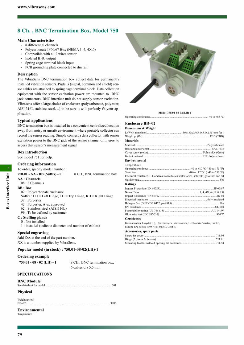
www.vibrasens.com
79
Box
es In
terf
ace
Uni
t
8
8 Ch. , BNC Termination Box, Model 750Main Characteristics• 8differentialchannels• PolycarbonateIP66/67Box(NEMA1,4,4X,6)• Compatiblewithall2wiressensor• IsolatedBNCoutput• Springcageterminalblockinput• PCBgroundingplateconnectedtodinrail
DescriptionTheVibraSens BNC termination box collect data for permanentlyinstalledvibrationsensors.Pigtails(signal,commonandshield)sen-sorcablesareattachedtospringcageterminalblock.Datacollectionequipmentwith the sensor excitation power aremounted to BNCjackconnectors.BNCinterfaceunitdonotsupplysensorexcitation.Vibrasensofferalargechoiceofenclosure(polycarbonate,polyester,AISI316Lstainlesssteel,..)tobesureitwillperfectlyfityourap-plication.
Typical applicationsBNCterminationboxisinstalledinaconvenientcentralizedlocationawayfromnoisyorunsafeenvironmentwhereportablecollectorcanrecordthesensorreading.SimplyconnectadatacollectorwithsensorexcitationpowertotheBNCjackofthesensorchannelofinteresttoaccessthatsensor’smeasurementsignal
Box introductionSeemodel751forhelp.
Ordering informationToorder,specifymodelnumber:750.01 - AA - BB (Suffix) - C 8CH., BNCterminationboxAA : Channels08:8Channels
BB : Box02:PolycarbonateenclosureSuffix:LH=LeftHinge,TH=TopHinge,RH=RightHinge32:Polyester42:Polyester,Atexapproved62:Stainlesssteel(AISI316L)99:Tobedefinedbycustomer
C : Stuffing glands0:Notinstalled1:installed(indicatediameterandnumberofcables)
Special engravingAddZxxattheendofthepartnumber.XXisanumbersuppliedbyVibraSens.
Popular model (in stock) : 750.01-08-02(LH)-1
Ordering example750.01 - 08 - 02 (LH) - 1 8CH.,BNCterminationbox,
6cablesdia5.5mm
SPECIFICATIONS
BNC ModuleSeedatasheetformodel............................................................................................ 301
Physical
Weightgr(oz)BB=02..................................................................................................................... TBD
EnvironmentalTemperature:
Model 750.01-08-02(LH)-1Fig 1 : Outline drawing, model 750.01-08-02(LH)-1Operatingcontinuous................................................................................ -40to+85°C
Enclosure BB=02Dimensions & WeightLxWxHmm(inch)............................................... 130x130x75(5.1x5.1x2.95)seefig1Weightgr(Oz).............................................................................................TBD(TBD)MaterialsMaterial.................................................................................................... PolycarbonateBaseandcovercolor...................................................................................... RAL7035Coverscrew(color)............................................................................ Polyamide(Grey)Gasketmaterial..................................................................................TPEPolyurethaneEnvironmentalTemperature:Operatingcontinous......................................................... -40to+80°C(-40to175°F)Shortterm....................................................................... -40to+120°C(-40to250°F)Chemicalresistance... Goodresistancetoseawater,acids,solvents,gasolinesandoilOutdooruse............................................................................................................... YesRatingsIngressProtection(EN60529)...........................................................................IP66/67NemaClass....................................................................................1,4,4X,6(12&13)ImpactResistance(EN50102).............................................................................. IK08Electricalinsultaion................................................................................. fullyinsulatedHalogenfree(DIN/VDE0472,part815)................................................................. YesUVresistance......................................................................................................UL508Flammabilityrating(UL746C5).................................................................. UL945VGlowwiretest(IEC695-2-1)...............................................................................960°CCertificatesGermanischerLloyd(GL),UnderwritersLaboratories,DetNorskeVeritas,Fimko,EuropeEN502981998/EN60950,GostRAccessories, spare partsScrewforcover................................................................................................... 711.96Hinge(2pieces&Screws)................................................................................ 711.91Mountingfootkitwithoutopeningtheenclosure................................................ 711.94
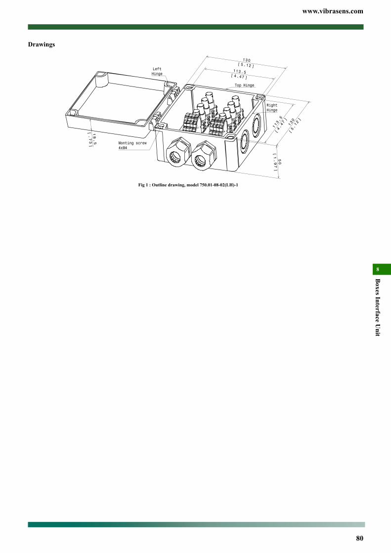
www.vibrasens.com
80
Boxes Interface U
nit
8
Drawings8 Ch. , BNC Termination Box, Model 750Main Characteristics• 8differentialchannels• PolycarbonateIP66/67Box(NEMA1,4,4X,6)• Compatiblewithall2wiressensor• IsolatedBNCoutput• Springcageterminalblockinput• PCBgroundingplateconnectedtodinrail
DescriptionTheVibraSens BNC termination box collect data for permanentlyinstalledvibrationsensors.Pigtails(signal,commonandshield)sen-sorcablesareattachedtospringcageterminalblock.Datacollectionequipmentwith the sensor excitation power aremounted to BNCjackconnectors.BNCinterfaceunitdonotsupplysensorexcitation.Vibrasensofferalargechoiceofenclosure(polycarbonate,polyester,AISI316Lstainlesssteel,..)tobesureitwillperfectlyfityourap-plication.
Typical applicationsBNCterminationboxisinstalledinaconvenientcentralizedlocationawayfromnoisyorunsafeenvironmentwhereportablecollectorcanrecordthesensorreading.SimplyconnectadatacollectorwithsensorexcitationpowertotheBNCjackofthesensorchannelofinteresttoaccessthatsensor’smeasurementsignal
Box introductionSeemodel751forhelp.
Ordering informationToorder,specifymodelnumber:750.01 - AA - BB (Suffix) - C 8CH., BNCterminationboxAA : Channels08:8Channels
BB : Box02:PolycarbonateenclosureSuffix:LH=LeftHinge,TH=TopHinge,RH=RightHinge32:Polyester42:Polyester,Atexapproved62:Stainlesssteel(AISI316L)99:Tobedefinedbycustomer
C : Stuffing glands0:Notinstalled1:installed(indicatediameterandnumberofcables)
Special engravingAddZxxattheendofthepartnumber.XXisanumbersuppliedbyVibraSens.
Popular model (in stock) : 750.01-08-02(LH)-1
Ordering example750.01 - 08 - 02 (LH) - 1 8CH.,BNCterminationbox,
6cablesdia5.5mm
SPECIFICATIONS
BNC ModuleSeedatasheetformodel............................................................................................ 301
Physical
Weightgr(oz)BB=02..................................................................................................................... TBD
EnvironmentalTemperature:
Model 750.01-08-02(LH)-1Fig 1 : Outline drawing, model 750.01-08-02(LH)-1
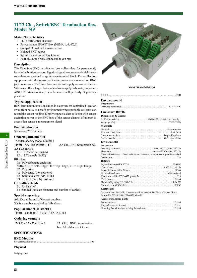
www.vibrasens.com
81
Box
es In
terf
ace
Uni
t
8
BB=02..................................................................................................................... TBD
EnvironmentalTemperature:Operatingcontinuous................................................................................ -40to+85°C
Enclosure BB=02Dimensions & WeightLxWxHmm(inch)............................................... 130x180x75(5.1x6.9x2.95)seefig1Weightgr(Oz).............................................................................................TBD(TBD)MaterialsMaterial.................................................................................................... PolycarbonateBaseandcovercolor...................................................................................... RAL7035Coverscrew(color)............................................................................ Polyamide(Grey)Gasketmaterial..................................................................................TPEPolyurethaneEnvironmentalTemperature:Operatingcontinous......................................................... -40to+80°C(-40to175°F)Shortterm....................................................................... -40to+120°C(-40to250°F)Chemicalresistance... Goodresistancetoseawater,acids,solvents,gasolinesandoilOutdooruse............................................................................................................... YesRatingsIngressProtection(EN60529)...........................................................................IP66/67NemaClass....................................................................................1,4,4X,6(12&13)ImpactResistance(EN50102).............................................................................. IK08Electricalinsultaion................................................................................. fullyinsulatedHalogenfree(DIN/VDE0472,part815)................................................................. YesUVresistance......................................................................................................UL508Flammabilityrating(UL746C5).................................................................. UL945VGlowwiretest(IEC695-2-1)...............................................................................960°CCertificatesGermanischerLloyd(GL),UnderwritersLaboratories,DetNorskeVeritas,Fimko,EuropeEN502981998/EN60950,GostRAccessories, spare partsScrewforcover................................................................................................... 711.96Hinge(2pieces&Screws)................................................................................ 711.91Mountingfootkitwithoutopeningtheenclosure................................................ 711.94
11/12 Ch. , Switch/BNC Termination Box, Model 749Main Characteristics• 11/12differentialchannels• PolycarbonateIP66/67Box(NEMA1,4,4X,6)• Compatiblewithall2wiressensor• IsolatedBNCoutput• Springcageterminalblockinput• PCBgroundingplateconnectedtodinrail
DescriptionTheVibraSens BNC termination box collect data for permanentlyinstalledvibrationsensors.Pigtails(signal,commonandshield)sen-sorcablesareattachedtospringcageterminalblock.Datacollectionequipmentwith the sensor excitation power aremounted to BNCjackconnectors.BNCinterfaceunitdonotsupplysensorexcitation.Vibrasensofferalargechoiceofenclosure(polycarbonate,polyester,AISI316Lstainlesssteel,..)tobesureitwillperfectlyfityourap-plication.
Typical applicationsBNCterminationboxisinstalledinaconvenientcentralizedlocationawayfromnoisyorunsafeenvironmentwhereportablecollectorcanrecordthesensorreading.SimplyconnectadatacollectorwithsensorexcitationpowertotheBNCjackofthesensorchannelofinteresttoaccessthatsensor’smeasurementsignal
Box introductionSeemodel751forhelp.
Ordering informationToorder,specifymodelnumber:749.01 - AA - BB (Suffix) - C AACH., BNCterminationboxAA : Channels11:11Channels(Switch)12:12Channels(BNC)
BB : Box02:PolycarbonateenclosureSuffix:LH=LeftHinge,TH=TopHinge,RH=RightHinge32:Polyester42:Polyester,Atexapproved62:Stainlesssteel(AISI316L)99:Tobedefinedbycustomer
C : Stuffing glands0:Notinstalled1:installed(indicatediameterandnumberofcables)
Special engravingAddZxxattheendofthepartnumber.XXisanumbersuppliedbyVibraSens.
Popular model (in stock) :749.01-11-02(LH)-1/749.01-12-02(LH)-1
Ordering example749.01 - 12 - 02 (LH) - 1 12 CH., BNC termination
box,10cablesdia5.8mm
SPECIFICATIONS
BNC ModuleSeedatasheetformodel............................................................................................ 300
Physical
Weightgr(oz)
Model 749.01-12-02(LH)-1
Fig 1 : Outline drawing, model 749.01-12-02(LH)-1
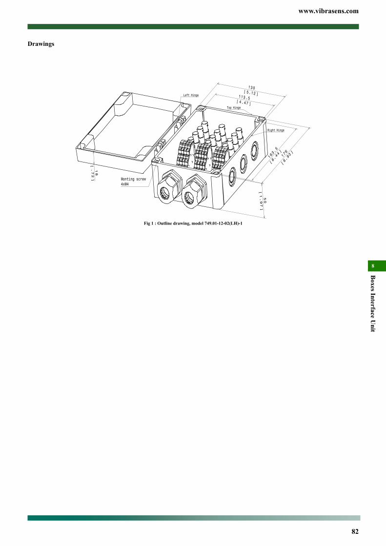
www.vibrasens.com
82
Boxes Interface U
nit
8
Drawings11/12 Ch. , Switch/BNC Termination Box, Model 749Main Characteristics• 11/12differentialchannels• PolycarbonateIP66/67Box(NEMA1,4,4X,6)• Compatiblewithall2wiressensor• IsolatedBNCoutput• Springcageterminalblockinput• PCBgroundingplateconnectedtodinrail
DescriptionTheVibraSens BNC termination box collect data for permanentlyinstalledvibrationsensors.Pigtails(signal,commonandshield)sen-sorcablesareattachedtospringcageterminalblock.Datacollectionequipmentwith the sensor excitation power aremounted to BNCjackconnectors.BNCinterfaceunitdonotsupplysensorexcitation.Vibrasensofferalargechoiceofenclosure(polycarbonate,polyester,AISI316Lstainlesssteel,..)tobesureitwillperfectlyfityourap-plication.
Typical applicationsBNCterminationboxisinstalledinaconvenientcentralizedlocationawayfromnoisyorunsafeenvironmentwhereportablecollectorcanrecordthesensorreading.SimplyconnectadatacollectorwithsensorexcitationpowertotheBNCjackofthesensorchannelofinteresttoaccessthatsensor’smeasurementsignal
Box introductionSeemodel751forhelp.
Ordering informationToorder,specifymodelnumber:749.01 - AA - BB (Suffix) - C AACH., BNCterminationboxAA : Channels11:11Channels(Switch)12:12Channels(BNC)
BB : Box02:PolycarbonateenclosureSuffix:LH=LeftHinge,TH=TopHinge,RH=RightHinge32:Polyester42:Polyester,Atexapproved62:Stainlesssteel(AISI316L)99:Tobedefinedbycustomer
C : Stuffing glands0:Notinstalled1:installed(indicatediameterandnumberofcables)
Special engravingAddZxxattheendofthepartnumber.XXisanumbersuppliedbyVibraSens.
Popular model (in stock) :749.01-11-02(LH)-1/749.01-12-02(LH)-1
Ordering example749.01 - 12 - 02 (LH) - 1 12 CH., BNC termination
box,10cablesdia5.8mm
SPECIFICATIONS
BNC ModuleSeedatasheetformodel............................................................................................ 300
Physical
Weightgr(oz)
Model 749.01-12-02(LH)-1
Fig 1 : Outline drawing, model 749.01-12-02(LH)-1
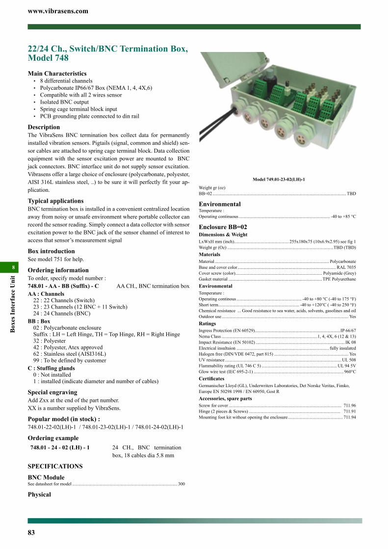
www.vibrasens.com
83
Box
es In
terf
ace
Uni
t
8
Weightgr(oz)BB=02..................................................................................................................... TBD
EnvironmentalTemperature:Operatingcontinuous................................................................................ -40to+85°C
Enclosure BB=02Dimensions & WeightLxWxHmm(inch)................................................ 255x180x75(10x6.9x2.95)seefig1Weightgr(Oz).............................................................................................TBD(TBD)MaterialsMaterial.................................................................................................... PolycarbonateBaseandcovercolor...................................................................................... RAL7035Coverscrew(color)............................................................................ Polyamide(Grey)Gasketmaterial..................................................................................TPEPolyurethaneEnvironmentalTemperature:Operatingcontinous......................................................... -40to+80°C(-40to175°F)Shortterm....................................................................... -40to+120°C(-40to250°F)Chemicalresistance... Goodresistancetoseawater,acids,solvents,gasolinesandoilOutdooruse............................................................................................................... YesRatingsIngressProtection(EN60529)...........................................................................IP66/67NemaClass....................................................................................1,4,4X,6(12&13)ImpactResistance(EN50102).............................................................................. IK08Electricalinsultaion................................................................................. fullyinsulatedHalogenfree(DIN/VDE0472,part815)................................................................. YesUVresistance......................................................................................................UL508Flammabilityrating(UL746C5).................................................................. UL945VGlowwiretest(IEC695-2-1)...............................................................................960°CCertificatesGermanischerLloyd(GL),UnderwritersLaboratories,DetNorskeVeritas,Fimko,EuropeEN502981998/EN60950,GostRAccessories, spare partsScrewforcover................................................................................................... 711.96Hinge(2pieces&Screws)................................................................................ 711.91Mountingfootkitwithoutopeningtheenclosure................................................ 711.94
22/24 Ch., Switch/BNC Termination Box, Model 748Main Characteristics• 8differentialchannels• PolycarbonateIP66/67Box(NEMA1,4,4X,6)• Compatiblewithall2wiressensor• IsolatedBNCoutput• Springcageterminalblockinput• PCBgroundingplateconnectedtodinrail
DescriptionTheVibraSens BNC termination box collect data for permanentlyinstalledvibrationsensors.Pigtails(signal,commonandshield)sen-sorcablesareattachedtospringcageterminalblock.Datacollectionequipmentwith the sensor excitation power aremounted to BNCjackconnectors.BNCinterfaceunitdonotsupplysensorexcitation.Vibrasensofferalargechoiceofenclosure(polycarbonate,polyester,AISI316Lstainlesssteel,..)tobesureitwillperfectlyfityourap-plication.
Typical applicationsBNCterminationboxisinstalledinaconvenientcentralizedlocationawayfromnoisyorunsafeenvironmentwhereportablecollectorcanrecordthesensorreading.SimplyconnectadatacollectorwithsensorexcitationpowertotheBNCjackofthesensorchannelofinteresttoaccessthatsensor’smeasurementsignal
Box introductionSeemodel751forhelp.
Ordering informationToorder,specifymodelnumber:748.01 - AA - BB (Suffix) - C AACH., BNCterminationboxAA : Channels22:22Channels(Switch)23:23Channels(12BNC+11Switch)24:24Channels(BNC)
BB : Box02:PolycarbonateenclosureSuffix:LH=LeftHinge,TH=TopHinge,RH=RightHinge32:Polyester42:Polyester,Atexapproved62:Stainlesssteel(AISI316L)99:Tobedefinedbycustomer
C : Stuffing glands0:Notinstalled1:installed(indicatediameterandnumberofcables)
Special engravingAddZxxattheendofthepartnumber.XXisanumbersuppliedbyVibraSens.
Popular model (in stock) :748.01-22-02(LH)-1/748.01-23-02(LH)-1/748.01-24-02(LH)-1
Ordering example748.01 - 24 - 02 (LH) - 1 24 CH., BNC termination
box,18cablesdia5.8mm
SPECIFICATIONS
BNC ModuleSeedatasheetformodel............................................................................................ 300
Physical
Model 749.01-23-02(LH)-1
Fig 1 : Outline drawing, model 749.01-23-02(TH)-1
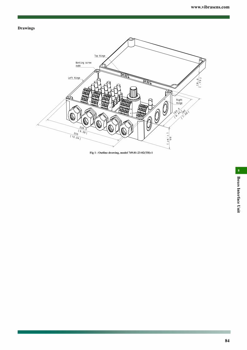
www.vibrasens.com
84
Boxes Interface U
nit
8
Drawings22/24 Ch., Switch/BNC Termination Box, Model 748Main Characteristics• 8differentialchannels• PolycarbonateIP66/67Box(NEMA1,4,4X,6)• Compatiblewithall2wiressensor• IsolatedBNCoutput• Springcageterminalblockinput• PCBgroundingplateconnectedtodinrail
DescriptionTheVibraSens BNC termination box collect data for permanentlyinstalledvibrationsensors.Pigtails(signal,commonandshield)sen-sorcablesareattachedtospringcageterminalblock.Datacollectionequipmentwith the sensor excitation power aremounted to BNCjackconnectors.BNCinterfaceunitdonotsupplysensorexcitation.Vibrasensofferalargechoiceofenclosure(polycarbonate,polyester,AISI316Lstainlesssteel,..)tobesureitwillperfectlyfityourap-plication.
Typical applicationsBNCterminationboxisinstalledinaconvenientcentralizedlocationawayfromnoisyorunsafeenvironmentwhereportablecollectorcanrecordthesensorreading.SimplyconnectadatacollectorwithsensorexcitationpowertotheBNCjackofthesensorchannelofinteresttoaccessthatsensor’smeasurementsignal
Box introductionSeemodel751forhelp.
Ordering informationToorder,specifymodelnumber:748.01 - AA - BB (Suffix) - C AACH., BNCterminationboxAA : Channels22:22Channels(Switch)23:23Channels(12BNC+11Switch)24:24Channels(BNC)
BB : Box02:PolycarbonateenclosureSuffix:LH=LeftHinge,TH=TopHinge,RH=RightHinge32:Polyester42:Polyester,Atexapproved62:Stainlesssteel(AISI316L)99:Tobedefinedbycustomer
C : Stuffing glands0:Notinstalled1:installed(indicatediameterandnumberofcables)
Special engravingAddZxxattheendofthepartnumber.XXisanumbersuppliedbyVibraSens.
Popular model (in stock) :748.01-22-02(LH)-1/748.01-23-02(LH)-1/748.01-24-02(LH)-1
Ordering example748.01 - 24 - 02 (LH) - 1 24 CH., BNC termination
box,18cablesdia5.8mm
SPECIFICATIONS
BNC ModuleSeedatasheetformodel............................................................................................ 300
Physical
Model 749.01-23-02(LH)-1
Fig 1 : Outline drawing, model 749.01-23-02(TH)-1

www.vibrasens.com
85
Box
es In
terf
ace
Uni
t
8
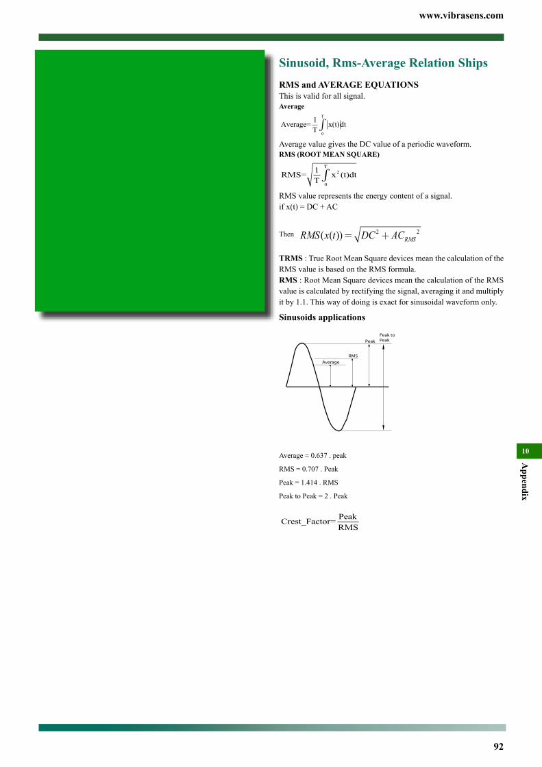
www.vibrasens.com
92
Appendix
10
Sinusoid, Rms-Average Relation ShipsRMS and AVERAGE EQUATIONSThis is valid for all signal.Average
Average=1
Tx(t)dt
0
T
ò
Average value gives the DC value of a periodic waveform.RMS (ROOT MEAN SQUARE)
RMS=1
Tx (t)dt2
0
T
ò
RMS value represents the energy content of a signal.if x(t) = DC + AC
Then RMS x t DC ACRMS( ( ))= +2 2
TRMS : True Root Mean Square devices mean the calculation of the RMS value is based on the RMS formula.RMS : Root Mean Square devices mean the calculation of the RMS value is calculated by rectifying the signal, averaging it and multiply it by 1.1. This way of doing is exact for sinusoidal waveform only.
Sinusoids applications
Average
RMS
Peak
Peak toPeak
Average = 0.637 . peak
RMS = 0.707 . Peak
Peak = 1.414 . RMS
Peak to Peak = 2 . Peak
Crest_Factor=Peak
RMS
Contents
Sinusoid, Rms-Average Relation Ships ......................................92
Displacement, Velocity, Acceleration, Relationships .................93
Nomogram (Metric) .....................................................................94
Conversion Factors, Dynamic .....................................................95
Mathematics .................................................................................95
Conversion Factors ......................................................................95
Wire Gauge ...................................................................................96
DIN Norms ....................................................................................97
Acronyms And Abbreviations .....................................................97
Decimal - Inches ...........................................................................98
Polymer Characteristics ..............................................................99
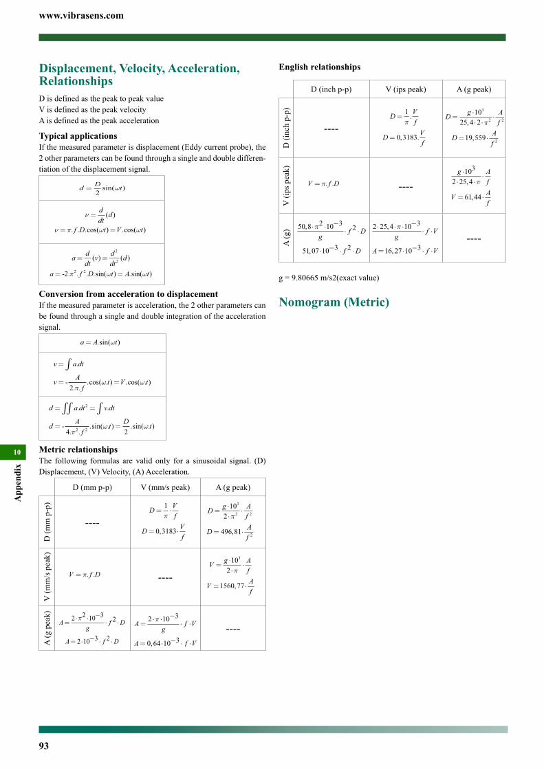
www.vibrasens.com
93
App
endi
x
10
Displacement, Velocity, Acceleration, RelationshipsD is defined as the peak to peak valueV is defined as the peak velocityA is defined as the peak acceleration
Typical applicationsIf the measured parameter is displacement (Eddy current probe), the 2 other parameters can be found through a single and double differen-tiation of the displacement signal.
d D t=2sin( )w
ν
ν π ω ω
=
= =
ddtd
f D t V t
( )
. . .cos( ) .cos( )
a ddtv d
dtd
a f D t A t
= =
= =
( ) ( )
- . . . .sin( ) .sin( )
2
2
2 22 π ω ω
Conversion from acceleration to displacementIf the measured parameter is acceleration, the 2 other parameters can be found through a single and double integration of the acceleration signal.
a A t= .sin( )w
v a dt
v Af
t V t
=
= =
∫ .
-. .
.cos( . ) .cos( . )2 π
ω ω
d a dt v dt
d Af
t D t
= =
= =
∫∫ ∫. .
-. .
.sin( . ) .sin( . )
2
2 24 2πω ω
Metric relationshipsThe following formulas are valid only for a sinusoidal signal. (D) Displacement, (V) Velocity, (A) Acceleration.
D (mm p-p) V (mm/s peak) A (g peak)
D (m
m p
-p)
----D V
f
D Vf
= ⋅
= ⋅
1
0 3183
p
,
D g Af
D Af
=⋅⋅⋅
= ⋅
10
2
496 81
3
2 2
2
p
,
V (m
m/s
pea
k)
V f D= p. . ----V g A
f
V Af
=⋅⋅⋅
= ⋅
10
2
1560 77
3
p
,
A (g
pea
k)
Ag
f D
A f D
=⋅ ⋅ −
⋅ ⋅
= ⋅ − ⋅ ⋅
2 2 10 32
2 10 3 2
pA
gf V
A f V
=⋅ ⋅ −
⋅ ⋅
= ⋅ − ⋅ ⋅
2 10 3
0 64 10 3
p
,
----
English relationships
D (inch p-p) V (ips peak) A (g peak)
D (i
nch
p-p)
----D V
f
D Vf
=
=
1
0 3183
p.
, .
D g Af
D Af
=⋅⋅ ⋅
⋅
= ⋅
10
25 4 2
19 559
3
2 2
2
,
,
p
V (i
ps p
eak)
V f D= p. . ----g A
f
V Af
⋅⋅ ⋅
⋅
= ⋅
103
2 25 4
61 44
,
,
p
A (g
) 50 8 2 10 32
51 07 10 3 2
,
,
⋅ ⋅ −⋅ ⋅
⋅ − ⋅ ⋅
pg
f D
f D
2 25 4 10 3
16 27 10 3
⋅ ⋅ ⋅ −⋅ ⋅
= ⋅ − ⋅ ⋅
,
,
pg
f V
A f V----
g = 9.80665 m/s2(exact value)
Nomogram (Metric)
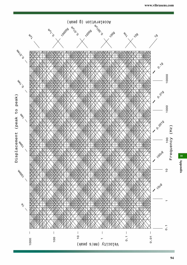
www.vibrasens.com
94
Appendix
10
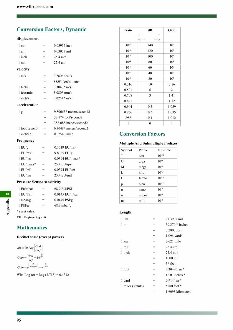
www.vibrasens.com
95
App
endi
x
10
Conversion Factors, Dynamicdisplacement
1 mm = 0.03937 inch1 um = 0.03937 mil1 inch = 25.4 mm1 mil = 25.4 um
velocity
1 m/s = 3.2808 feet/s= 88.0* feet/minute
1 feet/s = 0.3048* m/s1 feet/min = 5.080* mm/s1 inch/s = 0.0254* m/s
accelereation
1 g = 9.80665* meters/second2= 32.174 feet/second2= 386.088 inches/second2
1 foot/second2 = 0.3048* meters/second21 inch/s2 = 0.02540 m/s2
Frequency
1 EU/g = 0.1019 EU/ms-2
1 EU/ms-2 = 9.8065 EU/g1 EU/ips = 0.0394 EU/mm.s-1
1 EU/mm.s-1 = 25.4 EU/ips1 EU/mil = 0.0394 EU/um1 EU/um = 25.4 EU/mil
Pressure Sensor sensitivity
1 Eu/mbar = 68.9 EU/PSI1 EU/PSI = 0.0145 EU/mbar1 mbar/g = 0.0145 PSI/g1 PSI/g = 68.9 mbar/g
* exact value.
EU : Engineering unit
MathematicsDecibel scale (except power)
dB Log VoutVref
=
20.
Gain VoutVref
db
= =
10 20
Gain e edbLog e
db
= =
20 8 686( ) .
With Log (e) = Log (2.718) = 0.4342
Gain dB- +<- -- ---->
Gain
10-7 140 107
10-6 120 106
10-5 100 105
10-4 80 104
10-3 60 103
10-2 40 102
10-1 20 101
0.316 10 3.160.501 6 20.708 3 1.410.891 1 1.120.944 0.5 1.0590.966 0.3 1.035.988 0.1 1.012
1 0 1
Conversion FactorsMultiple And Submultiple Prefixes
Symbol Prefix Mul-tipleT tera 10+12
G giga 10+9
M mega 10+6
k kilo 10+3
f femto 10-15
p pico 10-12
n nano 10-9
u micro 10-6
m milli 10-3
Length
1 um = 0.03937 mil1 m = 39.370 * inches
= 3.2808 feet= 1.094 yards
1 km = 0.621 mile1 mil = 25.4 um1 inch = 25.4 mm
= 1000 mil= 3* feet
1 foot = 0.30480 m *= 12.0 inches *
1 yard = 0.9144 m *1 miles (statute) = 5280 feet *
= 1.6093 kilometers
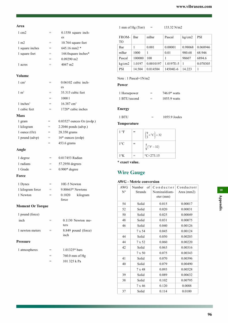
www.vibrasens.com
96
Appendix
10
Area
1 cm2 = 0.1550 square inch-es
1 m2 = 10.764 square feet1 square inches = 645.16 mm2 *1 square feet = 144.0square inches*
= 0.09290 m21 acres = 4047 m2
Volume
1 cm3 = 0.06102 cubic inch-es
1 m3 = 35.315 cubic feet
= 1000 l1 inches3 = 16.387 cm3
1 cubic feet = 1728* cubic inches
Mass1 gram = 0.03527 ounces Oz (avdp.)1 kilogram = 2.2046 ponds (advp.)1 ounce (Oz) = 28.350 grams1 pound (advp) = 16* ounces (avdp) = 453.6 grams
Angle
1 degree = 0.017453 Radian
1 radians = 57.2958 degrees1 Grade = 0.900* degree
Force
1 Dynes = 10E-5 Newton1 kilogram force = 9.80665* Newtons1 Newton = 0.1020 kilogram
force
Moment Or Torque
1 pound (force)
inch = 0.1130 Newton me-ters
1 newton meters = 8.849 pound (force) inch
Pressure
1 atmospheres = 1.01325* bars
= 760.0 mm of Hg= 101 325 k Pa
1 mm of Hg (Torr) = 133.32 N/m2
FROM-TO
Bar mBar Pascal kg/cm2 PSI
Bar 1 0.001 0.00001 0.98068 0.068946mBar 1000 1 0.01 980.68 68.946Pascal 100000 100 1 98607 6894.6kg/cm2 1.0197 0.0010197 1.0197E-5 1 0.070305PSI 14.504 0.014504 14504E-6 14.223 1
Note : 1 Pascal=1N/m2
Power
1 Horsepower = 746.0* watts1 BTU/second = 1055.9 watts
Energy
1 BTU = 1055.9 Joules
Temperature
1 °F = 9
532×°
+C
1°C = 5
932° −( )F
1°K = °C+273.15
* exact value.
Wire GaugeAWG - Metric conversion
AWG N°
Number of Strands
C o n d u c t o r Nominaldiam-
eter (mm)
Conduc to r r Area (mm2)
54 Solid 0.015 0.0001752 Solid 0.020 0.0003150 Solid 0.025 0.0004948 Solid 0.031 0.0007546 Solid 0.040 0.00126
7 x 54 0.045 0.0012444 Solid 0.050 0.0020344 7 x 52 0.060 0.0022042 Solid 0.063 0.00316
7 x 50 0.075 0.0034341 Solid 0.070 0.0039640 Solid 0.079 0.00490
7 x 48 0.093 0.0052839 Solid 0.089 0.0063238 Solid 0.102 0.00795
7 x 46 0.120 0.008837 Solid 0.114 0.0100
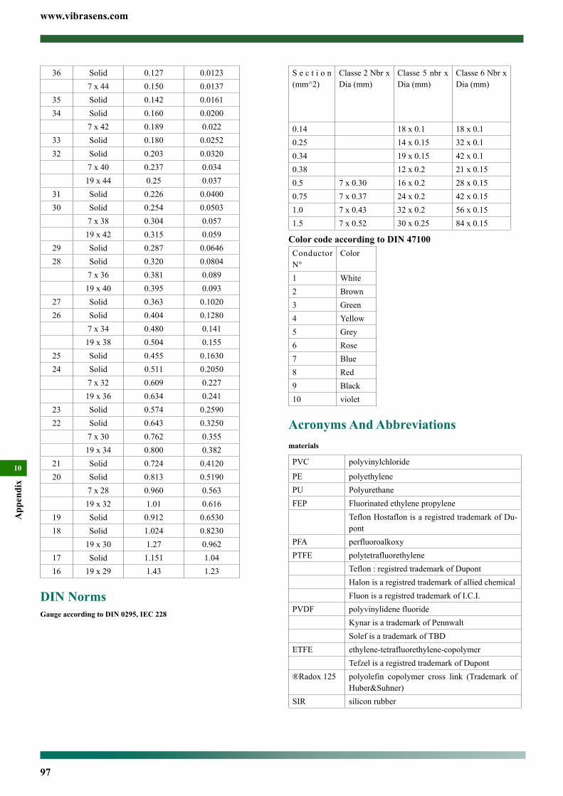
www.vibrasens.com
97
App
endi
x
10
36 Solid 0.127 0.01237 x 44 0.150 0.0137
35 Solid 0.142 0.016134 Solid 0.160 0.0200
7 x 42 0.189 0.02233 Solid 0.180 0.025232 Solid 0.203 0.0320
7 x 40 0.237 0.03419 x 44 0.25 0.037
31 Solid 0.226 0.040030 Solid 0.254 0.0503
7 x 38 0.304 0.05719 x 42 0.315 0.059
29 Solid 0.287 0.064628 Solid 0.320 0.0804
7 x 36 0.381 0.08919 x 40 0.395 0.093
27 Solid 0.363 0.102026 Solid 0.404 0.1280
7 x 34 0.480 0.14119 x 38 0.504 0.155
25 Solid 0.455 0.163024 Solid 0.511 0.2050
7 x 32 0.609 0.22719 x 36 0.634 0.241
23 Solid 0.574 0.259022 Solid 0.643 0.3250
7 x 30 0.762 0.35519 x 34 0.800 0.382
21 Solid 0.724 0.412020 Solid 0.813 0.5190
7 x 28 0.960 0.56319 x 32 1.01 0.616
19 Solid 0.912 0.653018 Solid 1.024 0.8230
19 x 30 1.27 0.96217 Solid 1.151 1.0416 19 x 29 1.43 1.23
DIN NormsGauge according to DIN 0295, IEC 228
S e c t i o n (mm^2)
Classe 2 Nbr x Dia (mm)
Classe 5 nbr x Dia (mm)
Classe 6 Nbr x Dia (mm)
0.14 18 x 0.1 18 x 0.10.25 14 x 0.15 32 x 0.10.34 19 x 0.15 42 x 0.10.38 12 x 0.2 21 x 0.150.5 7 x 0.30 16 x 0.2 28 x 0.150.75 7 x 0.37 24 x 0.2 42 x 0.151.0 7 x 0.43 32 x 0.2 56 x 0.151.5 7 x 0.52 30 x 0.25 84 x 0.15
Color code according to DIN 47100Conductor N°
Color
1 White2 Brown3 Green4 Yellow5 Grey6 Rose7 Blue8 Red9 Black10 violet
Acronyms And Abbreviationsmaterials
PVC polyvinylchloride
PE polyethylenePU PolyurethaneFEP Fluorinated ethylene propylene
Teflon Hostaflon is a registred trademark of Du-pont
PFA perfluoroalkoxyPTFE polytetrafluorethylene
Teflon : registred trademark of DupontHalon is a registred trademark of allied chemicalFluon is a registred trademark of I.C.I.
PVDF polyvinylidene fluorideKynar is a trademark of PennwaltSolef is a trademark of TBD
ETFE ethylene-tetrafluorethylene-copolymerTefzel is a registred trademark of Dupont
®Radox 125 polyolefin copolymer cross link (Trademark of Huber&Suhner)
SIR silicon rubber
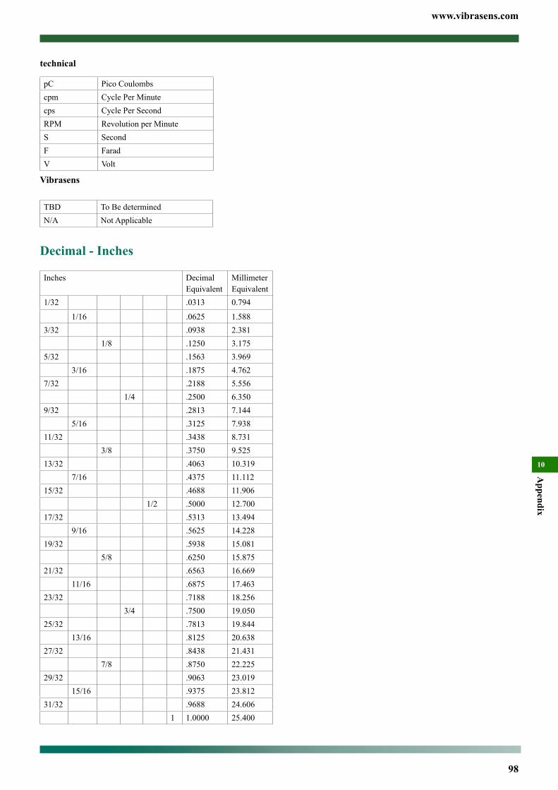
www.vibrasens.com
98
Appendix
10
technical
pC Pico Coulombscpm Cycle Per Minutecps Cycle Per SecondRPM Revolution per MinuteS SecondF FaradV Volt
Vibrasens
TBD To Be determinedN/A Not Applicable
Decimal - Inches
Inches DecimalEquivalent
MillimeterEquivalent
1/32 .0313 0.794
1/16 .0625 1.5883/32 .0938 2.381
1/8 .1250 3.1755/32 .1563 3.969
3/16 .1875 4.7627/32 .2188 5.556
1/4 .2500 6.3509/32 .2813 7.144
5/16 .3125 7.93811/32 .3438 8.731
3/8 .3750 9.52513/32 .4063 10.319
7/16 .4375 11.11215/32 .4688 11.906
1/2 .5000 12.70017/32 .5313 13.494
9/16 .5625 14.22819/32 .5938 15.081
5/8 .6250 15.87521/32 .6563 16.669
11/16 .6875 17.46323/32 .7188 18.256
3/4 .7500 19.05025/32 .7813 19.844
13/16 .8125 20.63827/32 .8438 21.431
7/8 .8750 22.22529/32 .9063 23.019
15/16 .9375 23.81231/32 .9688 24.606
1 1.0000 25.400
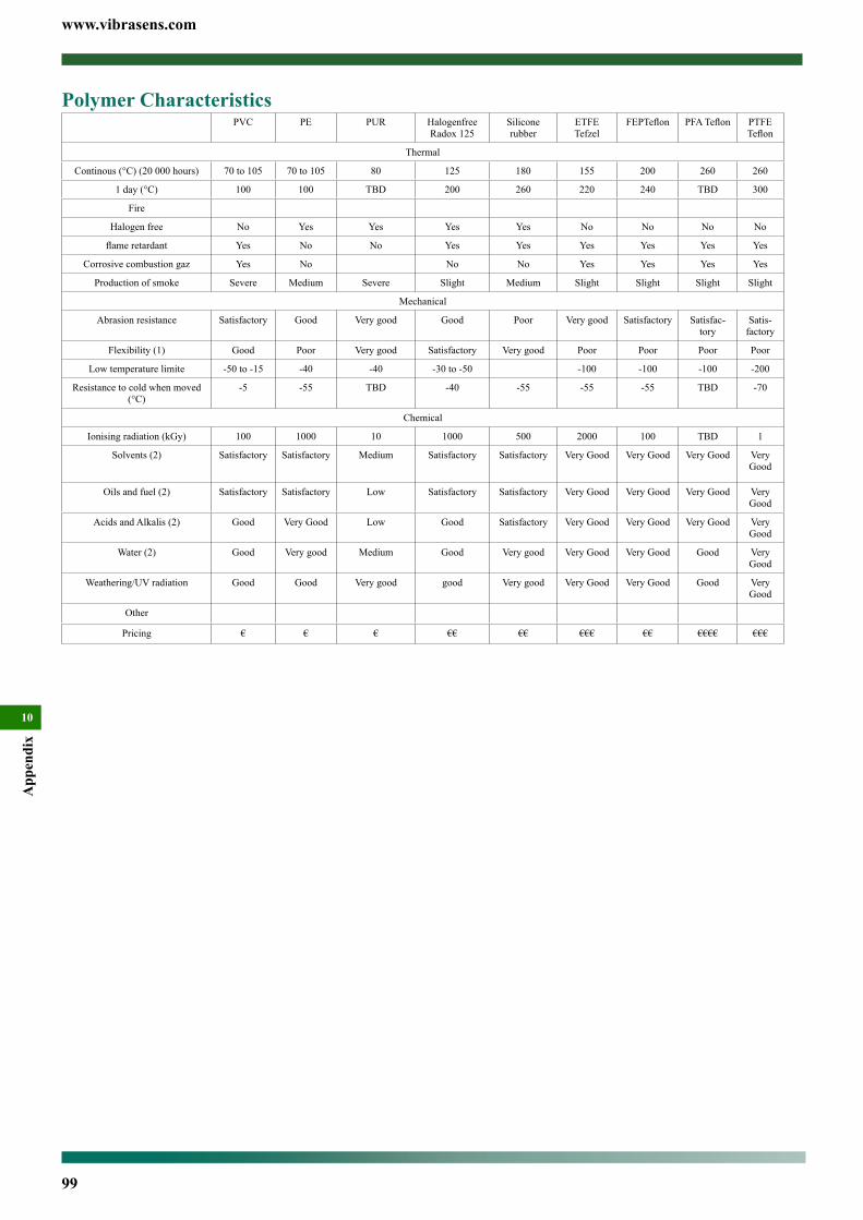
www.vibrasens.com
99
App
endi
x
10
Polymer CharacteristicsPVC PE PUR Halogenfree
Radox 125Silicone rubber
ETFE Tefzel
FEPTeflon PFA Teflon PTFE Teflon
Thermal
Continous (°C) (20 000 hours) 70 to 105 70 to 105 80 125 180 155 200 260 260
1 day (°C) 100 100 TBD 200 260 220 240 TBD 300
Fire
Halogen free No Yes Yes Yes Yes No No No No
flame retardant Yes No No Yes Yes Yes Yes Yes Yes
Corrosive combustion gaz Yes No No No Yes Yes Yes Yes
Production of smoke Severe Medium Severe Slight Medium Slight Slight Slight Slight
Mechanical
Abrasion resistance Satisfactory Good Very good Good Poor Very good Satisfactory Satisfac-tory
Satis-factory
Flexibility (1) Good Poor Very good Satisfactory Very good Poor Poor Poor Poor
Low temperature limite -50 to -15 -40 -40 -30 to -50 -100 -100 -100 -200
Resistance to cold when moved (°C)
-5 -55 TBD -40 -55 -55 -55 TBD -70
Chemical
Ionising radiation (kGy) 100 1000 10 1000 500 2000 100 TBD 1
Solvents (2) Satisfactory Satisfactory Medium Satisfactory Satisfactory Very Good Very Good Very Good Very Good
Oils and fuel (2) Satisfactory Satisfactory Low Satisfactory Satisfactory Very Good Very Good Very Good Very Good
Acids and Alkalis (2) Good Very Good Low Good Satisfactory Very Good Very Good Very Good Very Good
Water (2) Good Very good Medium Good Very good Very Good Very Good Good Very Good
Weathering/UV radiation Good Good Very good good Very good Very Good Very Good Good Very Good
Other
Pricing € € € €€ €€ €€€ €€ €€€€ €€€


VibraSens2e Avenue des Montboucons25000 BesanconFrance
PNR : 500008.06 rev 09/2008
ORDER NOW: [email protected] / Fax : +33 3-59-08-75-04 / Ph : + 33 3-63-53-45-10