Embed Size (px)
DESCRIPTION
stereo sonic
Citation preview

JOURNAL OF THE AUDIO ENGINEERING SOCIETY APRIL 1958, VOLUME 6, NUMBER 2
i
JOURNALREPRINT
:: The following paper is reprinted from the September 1957 issue of the Proceedings of the Institution: 'of Electrical Engineers, by kind permission of the Institution. Its concise presentation of the history,
theory, and psychoacoustic basis of the stereophonic effect makes this, in the Editor's opinion, an exceed-ingly valuable reference source.
r THE 'STEREOSONIC' RECORDING AND REPRODUCING SYSTEM
A Two-Channel System for Domestic Tape Records.
_'By H. A. M. CLARK, B.Sc.(Eng.), Member, G. F. DUTTON, Ph.D., B.Sc.(Eng.),and P. B. VANDERLYN, Associate Members.
(T/de paper was fit'3'[ received 7iii September, 1956, al;d itl rerised form 4th January, 1957. It was published in February, 1957, and was readb¢/bre the R^mo AND TELECOMMUNICATIONSECTION 20th February, 1957.)
SUMMARY d = Distance between loudspeaker base-line and theThe paper reviewsbrieflythe history of stcrcopbonic reproduction, listener.
The principal basic systems with their underlying ideas are described Ya= Fractional distance of apparent source fromand compared. Some account is given of the supposed mechanism central position.of natural binaural listeningfrom the viewpointof.directionlocalization. Yt = Fractional distance of true source from central
The principlesand practiceare discussedof a particular system for position.domestic use, derived from the early work of A. D. Blumlein, andcharacterized by the use of spaced loudspeakers driven in phase, to /_and y = Angles subtended by the left- and right-handwhich the name 'stereosonic' has been given. The aims of this system loudspeaker with respect to the median planeare defined,and thema'thematicaltheory involvedin its use isdeveloped, of the listener.Limitations and sources of error in the results achieved are described. ? -- Time-of-arrival difference of the sound from left-
Equipment used in thc making of master recordings and some of the and right-hand loudspeakers at the listenerproblems of studio technique involved are described. Consideration caused by path differences.
· is givento the form whicha domesticstereophonic record should take, /_£and/a R = Semi time differences at the listener's ears due toand the standards to which such a record should conform, together sounds from left and right loudspeakers.with the requirements which these impose on the reproducing 5_Land q5R = Resultant phaseof the sound at the left andequipment, rightearsofthelistenerrelativeto thecentre
position.LIST OF PRINCIPAL SYMBOLS
0 = Angle between radius vector of the sound source (1) THE IMPORTANCE OF STEREOPHONY IN SOUNDandthemedianplane. REPRODUCTION
0t = True angle. Normal listening is always binaural, and the two ears are0_ = Apparent angle, used in conjunction by the brain to interpret the sounds heard.h = Effective human-ear spacing. If all the individual sound sources, such as voices and instru-v = Velocity of sound in air. ments, and the reverberant sounds, are recorded or transmitted9_= Phase difference of sound at the listener's two by a single channel before being reproduced by one or more
ears. loudspeakers,it is not possibleto use the binaural senseofco = Angular fi'equency, location to differentiate between the various sounds as is done_b= Semi-angle subtended at the listener by a pair oC in direct listening.
loudspeakers. In order to add some spatialrealism,using only one channel/_: Difference of the time of arrival of the sound at a number of schemes have been tried, such as the use of spaced
the listener's two ears. loudspeakers supplied through frequency-dividingnetworks, orL and R = Peak amplitudes at listener's ears due to left and several loudspeakers fed through delay networks, but none of
right loudspeakers, these is universallysuccessfulon all types of programme.x = Half distance between loudspeakers. An honest assessment of the sound quality obtainable throughr = Projection of the listener's displacement from the a single channel, in which the frequency, harmonic, inter-
median plane on to the loudspeaker base-line, modulation and noise distortions have been reduced to the limitsexpressed as a fraction of x. detectable by the human ear, reveals that the reproduction._. is
still far from lifelike. The addition of real binaural hstenmgconditions seems to be the most likely factor remaining.
102
THE'STEREOSONIC'RECORDINGANDREPRODUCINGSYSTEM 103
Many tests have now been made which all show that, if a diately became more complex, for reasons which are discussedsystem is used in which the relative sounds at the two ears are later in the paper.each reproduced as similarly as possible to those heard in direct One of the earliest workers in this field was the late A. D.listening, i.e. with the correct relative amplitude and phase Blumlein. He was convinced at this time that the main contri-differences for each sound source, the reproduced sound takes bution towards the sense of spatial location was provided byon a new quality which is nearer to realism than can be obtained the difference in time of arrival at the two ears which, at lowin any otherway. frequencies,can be interpretedin terms of phasedifferences.
For a given amount of 'ambient' or reverberant sound, it is He invented a system 2 by which the phase difference betweenpossible to obtain better definition, i.e. ability to distinguish the outputs of two similar microphones spaced by a distanceindividual instruments or voices in a chorus. A soloist can be small compared with the wavelength, can be converted into twoheard clearly through an accompaniment, without having to in-phase outputs of different amplitudes driving two loudspeakersresort to making the soloist appear unnaturally close to the spaced by an appreciable distance. If the relative amplitudeslistener, correspondingto a givenphase differenceat the microphones
The problem of hearing clear bass parts free from the unduly are correctly proportioned, the phase differences at the twolong low-frequency reverberation which is so commonly ears of the person listening to the two loudspeakers will be aencountered, is considerably eased, and full bass response close simulation of the phase differences which the listenerwithout 'boom' can be obtained. It is noticeable that the would have heard had he been at the microphone position.reproduced sound level can be raised higher than with single- Blumlein showed how the correct relative loudspeaker inputschannel reproduction before the average listener becomes could be derived from two closely spaced pressure microphonesirritated. The ability to do this permits a closer reproduction by the use of suitable modifying networks which he calledof' the original dyriamic range of the music in cases where this 'shuffling' networks. He also showed how velocity microphonesis great. It also seems possible to obtain a given subjective could similarly be used, and solved the mathematical relationshiploudness for less acoustic power than with single-channel between the various parameters in order to obtain the correctoperation, apparent position of the source with an3; given loudspeaker
All this is quite aside from any benefits which may accrue arrangement. He also described a means of recording twofrom the ability to reproduce illusion of movements and the channels on a single disc, and, in fact, disc records of this typespatial relationships so essential to drama and opera, were pressed and reproduced in 1933. Experimental motion-
The requirements then seem to be to reproduce, with reasonable picture films were made incorporating twin-track opticaleconomy, in a system suitable for home use, the same sounds at recordings, and these were reproduced along with large-screeneach ear separately which would have been heard by direct projection in 1935. The industry was not prepared to introducelistening in an optimum position in front of the performers, the wide screen at this date, and therefore further work on theThis requirement can be limited to sounds arriving from direc- application was abandoned.tions covering an angle of, say, 90° in front of the observer for Blumlein's method has the advantage of being a 'free field'most practical purposes. No method has yet been devised to system, the observer being able to move his head without pro-meet this requirement from all horizontal directions, but neither ducing a corresponding movement of the apparent source. Itthis nor the need for the indication of vertical angular direction relies on the interaction of sounds from the two loudspeakersseemsto be of major significance, at the listener's ears, and cannot utilize headphones.
One of the first successful public demonstrations of stereo-(2) HISTORY phonic sound reproduction was given3 by Bell Laboratories in
An explanation of the principles by which the normal human America in 1934. The system used three microphones at thebeing uses both his ears for the purpose of spatial location has centre and extremities, respectively, of the sound stage, and theybeen sought since the classic studies in acoustics of the mid- drove, through three identical channels, three loudspeakersnineteenth century. Attempts to reproduce this natural ability similarly disposed on the reproducing stage. Using such aat a distance were made early in the development of telephony, three-channel system, fairly accurate location was obtained inOne of the earliest accounts was given in'L't_lectricien of 1881 the azinmth sense, and comparatively effective location wasby E. Hospitalier, who described the sound system installed in possible in depth. In 1939 R.C.A. used a similar arrangementthe Paris Opera House. t This basically consisted of a pair of with three channels for the stereophonic recording of a soundmicrophones spaced on opposite sides of the stage, which film entitled Fantasia.supplied at a distance a number of pairs of telephones held to Since the war demonstrations have been given by Philips atthe ears of the listeners, who received an impression of Eindhoven of a system using two microphones placed in an arti-localization, ficialhead,the outputsof whichsupplytwowidelyspacedloud-
It was probably not for many years, until sound reproduction speakers. In such a system the phase differences of thefor entertainment purposes was receiving more attention, that microphone outputs become of no particular significance whenany serious development work along these lines was undertaken, reproduced at the two spaced loudspeakers, but the relative ampli-It was well understood, however, that the use of two similar tudes of the microphone outputs due to masking by the artificialmicrophones spaced by a distance equivalent to that between a head are reproduced at the loudspeakers, and provide a measurehuman being's two ears, operating through two separate channels of spatial location to an observer in front of them. Such an effect,into a pair of headphones, did, in fact, give a remarkably accurate of course, can only take place at the upper frequencies, forimpression of spatial location. The use of headphones never- example those above about 700c/s, and any directional effect attheless robs the observer of the ability to locate sources outside the low frequencies is neglected.the horizontal plane and prevents discrimination between front More recently several American companies have madeand rear, since in these cases it is necessary to move the head recordings using two widely-spaced microphones driving spacedrelative to the sound field, loudspeakers via the medium of twin-track magnetic tapes, and
In the 1920's it became customary to use loudspeakers for one has issued some discs carrying the two channels, one On thesound-reproducing systems instead of head telephones, and the outer half and the other on the inner. This has the seriousproblem of reproducing sound with directional sense imme- disadvantage of halving the playing time.
104 H.A.M. CLARK,G. F.DUTTONANDP.B.VANDERLYN
The advent of magnetic tape, providing two synchronous The use of three independent amplifier and loudspeakerbut otherwise independent channels, made possible the eom- channels, although suitable for public use, is quite uneconomicalmercial exploitation of Blumlein's work, resulting in the for domestic use. The ultimate simplification of the wavefront'stereosonic' system described in this paper, system to two channels can, under certain conditions, give
This was demonstrated to members of the profession and pleasing results. For this purpose, two microphones are placedrepresentatives of the Press in April, 1955. In April, 1956, a about ten feet apart in front of the sound source, driving twofull-scale public demonstration at the Royal Festival Hall was identical amplifying and recording or transmitting systems with.givento an audienceof 1800. two loudspeakersat a similar separation. There is a decided
Iendency, however, for the sounds to appear to be coming fromthe two separate speakers, with a gap in between in which tho
(3) COMPARISON OF BASIC SYSTEMSIn the preceding brief historical review the systems employed sound is weak.
fall into three basic types.' These are described below. (3.2) The Reproduction of Correct Sound Pressures at the EarsA somewhat different approach to that of the wavefront con-
(3.1) The 'Wavefront' System ception is to consider local conditions at the observer's two ears.If an .infinite number of microphones, placed in a vertical A system has been devised which relies on a consideration of
plane between the source of sound and the listener, were to be these differences. The approach is based on the assumptionconnected to an infinite number of loudspeakers in corresponding that low-frequency sounds play little or no part in directionalpositions, clearly the radiated wave could be reproduced unaltered localization and that the principal clue to direction is the intensityand true binaural audition would be preserved, difference at high frequencies produced by the shadowing effect
A line, rather than an area, of microphones and loudspeakers of the head. It is shown that, if two pressure microphones arewould give perfect location in a horizontal direction, which is used as artificial ears in a dummy head, intensity differencesadequate for most purposes since location in a vertical plane between the outputs occur in accordance with the classic measure-seems to be impossible except by inclining the head. ments described in Reference 3. It is then demonstrated that,
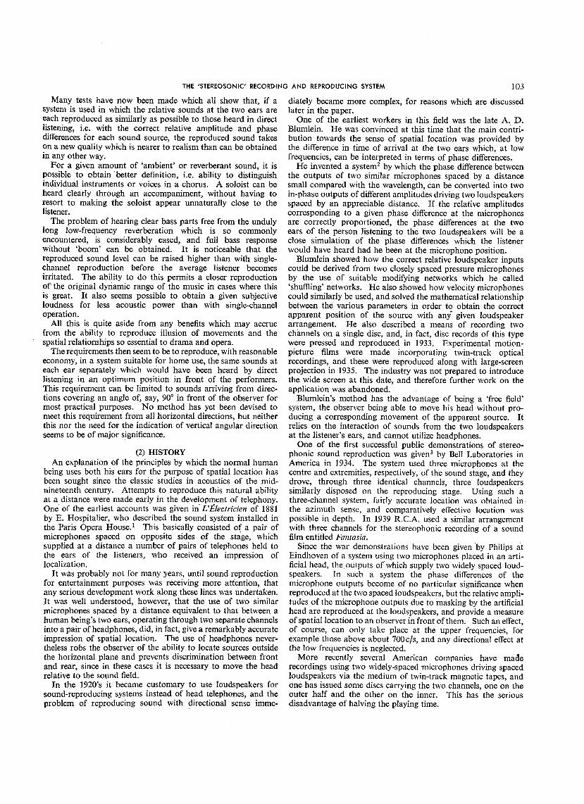
An approximation to this condition, with a corresponding if these outputs are applied to a pair of widely spaced loud-limitation in the accuracy of the results, can be obtained using a speakers placed symmetrically with respect to an observer,finite number of microphones and loudspeakers. Contemporary intensity differences do occur at his ears, although they are notfilm sound systems use several channels in this manner. The as great as the original differences at the microphones. Insystem described in Reference 3 also used this principle, connection with this system, attempts have been made to show
Fig. 1 shows the practical arrangement. Detailed tests were that time differences are less effective than intensity differencesin producing impressions of directional localization, and that
I0.25' }6'25' I-, _ i _ · incorrecttimedifferencescan be compensatedby modifyingthet ITRANSMIIIINGS'rUDIO J intensity differences. It is then argued that, since the major3 6 9J J -_ -_ _ --J-_- factor in localization,i.e. intensity differencesat high frequencies,t I -iE-.'_ _ --t2._' is reproduced, natural binaural listening is simulated.
.2_' I '__ The consideratidn of local conditions at the ears forms the
-- -- basis of the 'stereosonic' system, described in detail in Section4.This springs from the original Blumlein invention. It recognizes
Re HONKS that, since each loudspeaker communicates with both ears,
^MP"rl_j_. ? %C I differencesin magnitude of the sound pressures at the loud-ears,speakers at low frequencies produce phase and not magnitude
Ir nEIE,vIN'SIuD,OC * T i111 differences at the since the contributions from the twoUDSPEAKERS loudspeakers arrive at slightly differing times. A pair of direc-
_Ll_' , I I_..-_LOI___ .__._Z_ tional microphones is employed, effectively at a single position,to produce two outputs in phase, differing in amplitude accordingto the direction of the sound source. These are applied to a
·3'-'_ 22.5':l= j20'_5'- l pair of spaced loudspeakers so as to produce at the ears a time' ' I I I difference independent of frequency at low frequencies, and an
I intensity difference using the shadowing effect of the head ati l
lo3' 67' high frequencies. It is claimedthat this representsthe nearest
t approachyetmadeto naturallisteningconditions.
· I_ 221 - (3.3) Pseudo-Stereophonic Systems
_____.l_I___ No detailed description will be given of systems in which asingle microphone output supplies two or more recordingOBSERVERSchannels at relative levels which are controlled manually in thedubbingstage. Suchmeansare usedin the dialoguesequencesof wide-screen motion pictures and give an illusion of move-
Fig. 1.--Arrangement used by Bell Laboratories in 1934. ment to single voices, etc., but clearly cannot give a simultaneous
made with a loudspeaker located at one of nine positions in the representation of the direction of a large number of sources astransmitting studio, and the apparent position as estimated by is required for most musical programmed.observers in the listening studio corresponded fairly accurately inbreadth, and to a reasonable degree in depth, when the observers (4) THEORY OF THE 'STEREOSONIC' SYSTEMwere not too far from the centre-line. Very-high-fidelity channels Before discussing the theory in detail, it will be advisable towere used, and the quality of results obtained by this system was review briefly what is known of the mechanism of spatial auditorysaid to be better than anything ever heard prior to that date. location in the human being.

THE 'STEREOSONIC' RECORDING AND REPRODUCING SYSTEM 105
(4.1) Mechanism of Angular Localization response in adjacent nerve fibres containing the original infor-Rayfeigh4 in 1896, and Stewart s in 1920 both carried out marion in pulse coded form.
experiments which demonstrated that intensity differences atthe ears were insufficient to account for location at the lower (4.1.2) Action Potential.frequencies, and that the phase differences had to be taken into This secondary signal is called the 'action potential' and itaccount, although above about 1000c/s the intensity differences differs strikingly from the cochlear response. It consists ofwere necessary to avoid ambiguity. In spite of this and the work short pulses, of constant duration and amplitude, apparentlyof others, there has been some reluctance in many quarters to occurring at random intervals. The average frequency of theseaccept the importance of phase differences, pulses is related to the intensity of the original stimulus rather
Banister _ in 1931 and the Medical Research Council7 in 1932 than its frequency. This latter is determined in some othergive prominence to the idea that the time difference rather than way, possibly by observing which part or the basilar membrane
is responding, although it must be admitted that pitch dis-phase difference may be the element detected, in which casethere is no need for limitation of the effect to the lower frequencies, crimination is more accurate than can be accounted for by
In spite of this, and much other and more recent work, no simple resonance. Observations on single nerve fibres9 showexact explanation can yet be given for the mechanism of sound that successive pulses are always separated in time by an integrallocation. The authors believe that the two principal quantities multiple of the period of the stimulus and that they occur at aUsed by an observer to estimate the angle of arrival of a sound particular point on the cochlear response waveform.wave are, first, the difference in time of arrival of a wavefr0nt, When a pulse has been initiated the particular fibre in whichand secondly, the difference in intensity at the two ears. Of it occurs remains inactive for a short interval, known as thethese, by far the more important is the time difference. For 'refractory period', which varies according to the strength of thosinusoidal waves, a constant time difference at the two ears is stimulus. This mechanism limits the pulse rate in a single fibreequivalent to a relative phase diflbrence proportional to the to a few hundred per second. There are, however, many suchfrequency of the original sound. At low frequencies, where this nerve fibres associated with each ear, and it is known that atphase difference is less than, say, _r radians, the direction of least one fibre will respond at each cycle of the incoming stimulus,arrival could be deduced from it. For such a deduction to be up to a frequency of 1500c/s, perhaps higher.possible, the times of passage of each wavefront past both ears Provided, therefore, that the brain can recognize pail's ofmust be identifiable to the observer. As the frequency is pulses produced at the two ears by the same sound wave, theincreased, i.e. the wavefronts follow each other more closely, original time-difference information is available to it.the point is eventuallyreachedwhen a wavefrontarrivesat oneear before the preceding one has reached the other. Since there (4.1.3) Time-ComparisonSystem.is nothing to distinguish between the wavefronts, ambiguities It is clear that, if the above reasoning is correct, each cyclearise and it is impossible to interpret the observed time differences of the incoming wave gives rise to a pulse of action potentialuniquely in terms of direction of arrival. These ambiguities up to frequencies of about 1 500c/s, and that such pulses occurstart to occur when the ear spacing becomes equal to a at a definite point in the cycle. This happens at both ears, andhalf wavelength. At higher frequencies the head becomes an if there were some means of measuring the time differencesappreciable obstacle and produces an intensity difference, the between their production, the angle of arrival of the soundmagnitude of which can be used to assess the direction of arrival, could be deduced. A theory has been put forward by Jeffress l°It may also assist in resolving the ambiguities mentioned, and which suggests how this is done.allowing the observed time differences to be interpreted at It must be noted first that transmission of a pulse along ahigher frequencies. Recent work in America 8 shows that the nerve fibre is not simple electric transmission like that along adirection of arrival of pure tones can be judged unambiguously telephone cable. It is electrochemical in nature; pulses travelwith reasonably constant accuracy up to 1200c/s. i At this without attenuation as they are self-regenerating, and at afrequency the ear spacing approximates to a whole wavelength, relatively slow speed. The rates of transmission as measured dosuggesting that the first ambiguity due to confusion of wave- not exceed about 104cra/s, i.e. several times slower than thefronts is overcome, possibly with the assistance of intensity velocity of sound in air.differences. Jn this case the brain has to' choose between two The theory then postulates the existence of a nerve combina-possible directions, widely separated and on opposite sides of the tion such that one nerve requires to be stimulated by two othershead. simultaneously before it will respond. Engineers will recognize
Where the Sound waveform is complex, as in the majority of this combination as being analogous to the 'logical-and gate'natural cases, the shape of the modulation envelope probably ubiquitous in computer circuits. It is suggested that aassists in identifying the wavefr0nts and making possible the number of these nerve combinations are spread across theinterpretation of observed time differences, brain and stimulated by pairs of nerve fibres of appropriate
With pure tones at high frequencies, when it is necessary to length, connected to the two ears. Fig. 2 shows this schematically,in engineering terms, remembering that transmission times arerely on intensity differences to judge direction, accuracy
deteriorates, since the amplitude diffe£ences at the ears, eharac- proportional to the physical lengths of the different connections.teristic of the source position, may be modified by stationary A response from one of these 'gates' corresponds to a pair ofwaves and reflections from walls and other obstacles, pulses separated by a definite time interval arriving from the
two ears. Since the lengths of the nerve fibres are significant,(4.1.1)CochlearResponse. it is clear that the positionof the nervecombinationin the brain
When a sound wave arrives at the ear, the immediate result is associates it with a definite time interval between stimuli, andthe production of an electrical waveform corresponding to that thus with a definite direction of arrix)al of the original sound.of the instantaneous sound pressure. This is known as the In the Figure, a response from the left-hand gate corresponds to'cochlear response', and it can be detected by amplifying the a sound wave arriving from the right side of the observer andpotential differences between suitably placed electrodes. The vice versa.signal, in this form, is unsuitable for analysis by the brain, Some evidence in support Of this theory has recently beenand its primary purpose seems to be to initiate an electrochemical published. Experiments on cats are described TMin which clicks.

106 H. A. M. CLARK, O. F. DUTTON AND P. B. VANDERLYN
that he has been. conveyed to the optimum position for directlistening in the recording studio. So far as is known, the ratioof reverberant to direct sound provides the only clue to distanceof the source, except for any possible .change in quality due to
·absorption of high frequencies at a distance. In general,, thereverberation of the 'average· domestic room is small comparedwith that of concert halls used for large musical combinations,and so the sense of distance thus conveyed is not substantially
· altered.It is impossible to achieve this aim with perfection, but an
attempt is made in the system to reproduce the actual relativephases and thus the inter-aural time differences at the lowerfrequencies and the relative intensities at the upper frequencies.
It should also be clearly understood that the system is intendedto operate only with spaced loudspeakers and thus transmitthe spatial effect when listening in free space. The system will
Fig. 2.--Schematic of possible time-comparison system, not function correctly if the two channels are connected to leftand right headphones.
separated by a known time interval, were Supplied to the twoears independently and the response on the left and right lobes (4.3) Mathematical Theory _ "
of the brain observed. Maximum response was obtained from (4.3.1) Vector Pressures at Ears in Direct Listening.the right lobe when the click supplied to the left ear was advancedby a time corresponding to a sound coming from the left of the Fig. 3 shows an actual source of sound S before :two earssubject, and vice versa. EL and ER, spaced by a distance h in such a position that its
(4.1.4) ApplicatiOnof the Theory. sThe physiologyof the brain is insufficientlyknown to confirm _,
or deny the existence of such a mechanism as that postulated,nevertheless its extreme simplicity makes the idea attractive.The theory forms a useful working basis, and many of the k
-observedfacts can be fitted into it. It demonstrates clearly the e_N_--*importance of the first wavefront to arrive at the ears; this hasthe best chance of triggering a pulse, since the inhibitorymechanism is inoperative. The difficulty of localizing, pure'tonesat highfrequencyisalsoshown. Pairsofpulsesoriginating n,
from differentcyclesof the incomingwavewillproduce spurious _ARresponsesfrom the gates,whichthe brain willhave to 'discard. ERIt is thought that, under these conditions, intensity differences Xplay an important part. With complexhigh-frequencywave- A.forms, however, pulses will tend to be grouped round prominentfeatures in the waveform, and this will again enable the time Fig. 3.--Time differentialof sound at two ears fromcomparisonmechanismtooperate, obliquesource.
Altogether, the best chance of a clear direction seems to be directio n is at an angle 0 to'the face-on position. The sound toat those lower frequencies where the action-potential pulses . ER, however, will travel a distance ERAR further than, and thatcan only be ·paired in one way to give a time difference corre- to EL a distance ELAL less than, the average. Ifv is the velocity.spending to a possible angle of arrival. This does not mean of sound in air, the sound will take a time (hsin O)]2vto travel· that the most accurate indication will be obtained at the lowest from ELto AL. Thus the time interval between the arrivals offrequencies. The slower rate at which the waveform crosses sound at the two ears will be (/t sin 0)/v. Hence, if h is smallthe zero-pressure axis and the higher threshold as shown in the compared with the distance from the source, the magnitude atFletcher-Munson curves combine to produce a loss of resolution each ear will be the same, but there will be a phase differencethat appears as an error in estimated direction. Neverthelessthe sense of direction is very strong at low frequencies, and the cohsin 0authors do not subscribe to the view that low frequencies play _ _ v . ... .... (1)no Part in angular localizatioia.
' where co is 2:r times the frequency of the sound wave.
(4.2) The Aim of the 'Stereosonle' Syst?m At higher frequencies, ,_hen the wavelength is short comparedwith h, the phase angle will be large and ambiguous but the timeThe aim of the 'stereosonic' system is to reproduce at the ears delay will be the same. Owing to the masking effect ofthe
of the listener, in as large an area as'possible in front of a pair head, the magnitude is not subject to accurate calculation butof loudspeakers, the same vector sound pressures as he would has been determined experimentally. 12't3have experienced by direct listening in a corresponding position If these phase differences and magnitudes can be simulated inin front of the sound stage. In other words; although the spacing reproduction, the received sound will appear to come from thebetween the loudspeakers must, in general, be less than the same angle 0.width of the original sound source (except for some solo instru-ments and unaccompanied solo voices), if the apparent angular (4.3.2) ReproducingSystem.width of the reproduced sound is the same as that subtended at For domestic purposes it is generally permissible to use twothe optimum positio n for direct listening, the listener will imagine loudspeakers only, and they must be operated in such a way as

THE 'STEREOSONIC' RECORDING AND REPRODUCING SYSTEM 107
to reproduce as nearly as possible the required vector pressures possibly because it is accompanied by a certain degree of ampli-at the ears. Since the bulk of acoustic energy in music and tude cancellation. It has, however, been observed underspeech occurs below about 700cJs, it is important that the laboratory conditions. 8system should operate effectively at low frequencies.
In Fig. 4, WL and WR represent two similar loudspeakers (4.3.3) MicrophoneSystems.When Blumlein's first experiments were carried out in 1929-30
WL c 1 Wl:l the only readily available microphones were pressure-operated
;Jand had substantially circular polar diagrams. In order toobtain the required inputs to the' loudspeakers the first arrange-ment to be used consisted of two such pressure microphones
___ separatedby about 8 in (i.e. typicaldistancebetweenears).
The outputs were therefore the same in magnitude, for anysource angle, but there was a phase difference given by eqn. (1).To convert this into the required amplitude difference demandedby eqn. (2); an ingenious circuit was used in which the twomicrophone outputs were first summed and differenced to pro-duce two new voltages in quadrature. The difference voltage
- - rR was integrated, i.e. multiplied by a factor proportional to l[coand rotated by 90°. The surnvoltage was uniformly attenuatedby a suitable amount. These two modified voltages were again
Fig. 4.--Apparent source deduced from the time differehtial of sound summed and differenced, giving two final voltages, in phaseproduced at two cars by'two loudspeakers operating at different, but of different amplitudes, which it can be shown are of suchsoundlevels, valuesthat, when appliedto two loudspeakers,will, according
to eqn. (2), produce at the ears the same phase angles as thosesupplied with inputs which are. in phase but of different mag- at the microphones.nitudes. The loudspeakers subtend an angle 2¢ at a centrally:placed listener whose ears EL and E R are separated by a distanceh, which is assumed to be small compared with the loudspeaker s'distance. From eqn. (1) the phase differencebetweenEL and o, _ol --ER for sound coming from either speaker will be 2co/x= /'(coh sin ¢)]v, where 2/2 is the difference in time of arrival atEL and ER. ,45'_;"A'
Letthe averageinstantaneoussound pressureat both ears _be Lsin. cot from WL and Rsincot from WR. The sound : -_--
pressnresat eachearcanbe calculatedasfollows: _. !x,_;,__Average At E L At ER / ,NxFrom WL L sin cot L sin ro(t-f/0 L sin co(t it)
From WR R sin rot R sin coq-- t*) R'sin _o(t_ ti) Fig. S.--Polar characteristics of a palr of velocitymicrophones at 90°.
Total pressure at EL = L sin offt +/_) + R sin w(t -- i_)
[ ( )1 Fig' 5 represents tw° vel°city micr°pfi°nes' e'g' ribb°n type'L -- R with their axes ot' maximum response at 90°. Such microphones
=_v/(L2q-R2q_2LReos 2oJ/2)sin cot+ arc tan _ tan 0)/2 have a response which is .proportional to the sine of the angleSimilarly, the total pressure at ER is. between the source and the plane of the ribbon. A source St is
assumed to be at an angle Otfrom the median axis of the micro-
I (L--R)l phones. The outputs from the microphones will be in phase at·v'(L2+R2+2LR co32o0/2)sin _ot- arc tan _ tan toF all values of 0t if the microphones are placed on the samevertical axis but their outputs L and R are given byHence the phase difference between EL and E R is _62,
L -- R L cc sin (45° .+/_t)
where _2 = 2 arc tan (L_+-R tan co/2) R 'cc sin (45° 0,)
L -- R tohsin ¢\ whence it can be shown that/2 arc tan [,_-_-R= tan ---_-_ ) L -- R sin 0t
=tan0t . . . . (3)When oJ/2 and (;62< *ri2 L + g cos _
L -- R oJhsin ¢(/)2-- L + R v .... (2) (4.3.4) Performance of CompleteSystem at Low Frequencies.If the outputs of the microphones are connected (after suitable
Thus, if the loudspeakers are supplied in phase with correct amplification) to the loudspeakers, the resultant phase differencebetween the sounds at the ears will berelative amplitudes, the phase difference (32 at tl_e ears can be
made to be the same as that fi'om a sound source at any angle L -- R cohsin ¢within +¢. In addition, if L or R is permitted to become _2 -- L + R v .... (2)negative, i.e. to have a phase reversal, the apparent directionlies outside the limit o_ + ¢ at frequencies where this analysisis valid. This phenomenon is not readily observable in practice = tan 0t cohsin._ ¢ from eqn. (3),p
]08 H.A.M. CLARK,O. F.DUTTONANDP.B. VANDERLYN
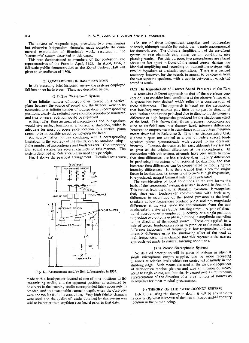
The ears will interpret this as an apparent sound source at an phones with mutually perpendicular axes of maximum response.angle 0a, where sin 0a = q_2v/wh, from eqn. (1); The outputs from these microphones can be summed and
differenced and the difference channel subjected to a loss of 3 dBi.e. sin 0a = tan0t sin _b ..... (4) at all frequencies 14 above 700c/s. These voltages are then
Fig. 6 shows the apparent angle plotted against the true angle again summed and differenced and used to supply two identicalfor various values of _b. It will be seen that, when the listener loudspeaker channels. If the loudspeakers are equidistant from
the observer and subtend an angle of approximately 90° at him,s he will receive substantially correct directional information at
eo_- _' ' _?_°_ et ailfrequencies within the spectrum. At greater distances from
so _ ///_ the loudspeakers the listener will observe the same apparent59 position of the source, relative to the loudspeakers.
4o An important feature of a system using two coincident velocity
/_/Ifl/ micr°ph°nes at 90° is that the r'm's' sum °f the °utputs °f th°
bJ
o so° loudspeakersis constantfor a sourceat a constantdistancef, ao
e /_ _ from the microphones, regardless of its direction. It is thiseo / 20° w wa feature which enables the system to reproduce a uniform sound
__ _ _ field betweenthe loudspeakers without the tendency to leave a_o / mo oa 'hole' in the centre. This latter effect can be very pronounced
h/_ _ _'__ I '_ with the spaced microphone system.o - ' (4.5)SourcesofError0 10 20 30 40 50
et, peg Although the two amplifying channels and the microphonesFig. 6.--Apparent angle plotted against true angle for velocity and loudspeakers have been assumed to be distortionless in tho
microphones at 90°. above explanation, it isclear that they cannot be perfectly matchedin amplitude and phase, particularly the transducers. Tho
is at such a distance that the loudspeakers subtend an angle of effect of the small inevitable differences in frequency response120°, the apparent angle is very close to the true angle up to can be calculated from the preceding theory, but such transducers+ 35°. When the listener is at other distances from the loud- will, in general, introduce phase shifts before amplitude differencesspeakers, but still on the centre line, the apparent source remains become very pronounced.at the same fraction of the total loudspeaker spacing, thus . Calculations show that a phase shift in one channel producesshowing that a correctly proportioned sound picture is presented no change in the central position; i.e. when the two channels amalthough the angular scale has been altered. The angular at the same level. A phase shift in one channel of as much asdistortion is such that the apparent source appears to be some- 90° can introduce error factors of 2 at small values of 0t, 1.5what nearer the centre than it should be over most of the range, at 0t = 26° and 1.2 at Ot= 39°.{4.3.5) Performanceat High Frequencies.
If the velocity microphones have a constant polar charac- ¢.5.1) Effectof AsymmetricListeningPosition.teristic at all 'frequencies, the ratio of voltages applied to the The preceding calculations have assumed an observer sym-loudspeakers is independent of frequency. At frequencies above metrically placed with regard to the loudspeakers and facing thoabout 700c/s, however, the foregoing analysis will not hold, centre line. If the observer turns his head the apparent sourcesince the phase angle between the pressures at EL and ER will be will appear to remain in the same position, as in natural listening,ambiguous. At these frequencies the masking effect of the head, but if he moves to either side of the centre line the apparenthowever, causes the left ear to be more affected by the left position will move in the same direction, e.g. from Sa to S_ inloudspeaker than by that on the right and vice versa, and it can Fig. 7.
be easily demonstrated experimentally that directional informa- 'w so s_,: x -wRtioncanbeconveyedat thehigherfrequencies. _, x ..Subjective tests were made with a number of observers using
two loudspeakers supplied with known relative voltages from asource of recorded music. First a filter was inserted passingall frequencies up to 700c/s from a variety of sources of sound oaincluding male and female speech, solo, orchestral and brass-band music. The experiment was repeated using all frequenciesabove 600c/s. Quite definite location within about +2 ° wasobtained in each case, but whereas at low frequencies the anglewas in agreement with that predicted from eqns. (1) and (2)for a given loudspeaker ratio, that obtained at high frequencieswas greater. The relationship obtained is in agreement withthat published by other workers who rely primarily on intensitydifferences._s By introducing a factor of approximately 0.7 Fig. 7._Change of position of apparent sourcewith displacedlisteninginto the ratio (L -- R)/(L + R) above 700 c/s, the results for position.high and low frequencies can be brought into line, except forextreme positions of the source. The reasons for this are, first, that the loudness from Wa
has increased and that from WL decreased, and their relative(4.4) Basis of Recording System phases are altered owing to the difference in the path lengths.
To meet the requirements set out in Section 4.2, therefore, Secondly, the angles subtended by the loudspeakers at' thethe microphone system can consist of a pair of velocity micro- observer have also become unequal. The effect of these

THE 'STEREOSONIC' RECORDING AND REPRODUCING SYSTEM J09
FINITEinequalities makes the calculation of apparent angle exceedingly FINITE/ MAXIMAlaborious, but it is possible, by makingsimplifying assumptions, mAXIMA'/
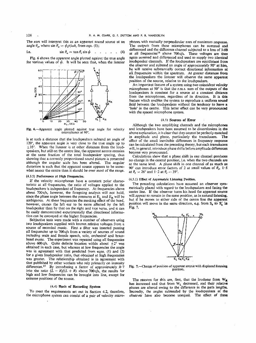
,.2 .... / _ tito appreciate their general effect. Fig. 8shows the position ,.el I I il JJlJJ/ J JJJ\]I !tJJJl J.of the apparent source of Fig. 7 for various listening positionsplotted against the positions of the real souree with respect to oJ J J J llJJJ'f {li[[li[l_]Jl] J
themicrophones.,.o In Fig. 8, r is the projection 0f the observer's 5 I..II I [3fill Ii/1\I/ it
o., xX_x 'N
. ,x x \ il,till I_, xNXX \ - - .
' x ,, x . !Ii,ri I JBIlII Io. X_,'_ X _, ,oo "" I ""1 ,ooo.i -- \ ..-1.o /su _ _ ,X ""' \ _ _ Fig. 9.--Apparent- position as a function of frequency for asymmetric
X?_L\ _._ -o.5 listeningposition.
'_XX_%. _V -O.l }bl gl: 118'4°'1.3° .
_' , ',_._,--o t,,)o,=o.(e) 0t = --18'4 °.
' 'N_ _ (.f) 0, _ --36'9 °.lq
Fortunately, at these critical frequencies the resultant mag-\_ _ nitude becomes small, thus allowing the remaining sound,
I [ _ whichhas smallphaseerrors,to predominate. Theimportance,1.o.o _o._ o O.5R _.o of scale is obvious from the curves; halving all dimensions will
APPARENTPOSITION,Ye allow the system to operate to twice the frequency before the
Fig. 8.--Apparent position plotted against true position for asym- anomalous regions are approached.metriclisteningposition. The effect of the offset listening position is worst for true
angles near the centre, when L and R have about the same
displacement on the loudspeaker base-line, expressed as a amplitude. (The extreme positions, 0r = + 45°, are unaffected,'fraction of x. The calculations ignore the effect of the path since only one loudspeaker is operating.)difference on the relative phases at the listener of the soundfrom WL and WR; i.e. it applieswhere sucha path differenceis (5) RECORDINGEQUIPMENT
small compared with a wavelength. The curves bear out the (5.1) Microphone Combinationsstatement that the apparent source moves in the direction of theobserver. (5.1.1)PressureMicrophones.
In order to take account of the effect of path differences it is As stated in Section 4.3.3, the earliest experiments werenecessary to fix the scale of the layout shown in Fig. 7, so that necessarily carried out with pressure microphones. These hada definite phase shift can be associated with any given listening substantially spherical polar diagrams--at least, at low ftc-position at a particular frequency. For this purpose let d equal quencies. The problem of prod.ucing magnitude differences10fl to represent a typical domestic arrangement. A listening was solved by giving them a small but definite spacing, summingposition is chosen corresponding to r = 0.5, and the apparent and differencing their outputs, and integrating the differenceposition is plotted against frequency in Fig. 9 for various values of vector before recombining to drive the loudspeakers. Thethe true angle 0t. It will be seen that, as the frequency increases significant parameter in such a case is the actual spacing employed.from zero, deviations from Fig. 8 are initially small, but they If this exceeds about a quarter wavelength of the highest workingincrease rapidly above 100c/s, reaching a maximum in the region frequency, the resultant outputs to the loudspeakers become ofof 200c/s, beyond which the function approaches its initial value opposite polarity and the system breaks down. Small spacingonce more before reaching a second maximum at about 600 c]s is desirable on this score. However, if the spacing is too small,and again returning to its original value, the difference vector will diminish until it is comparable with
The calculations have not been made for frequencies above the normal random differences in the microphones. Moreover,which the theory given in Section 4.3.2 is valid, the amplification in the difference channel has to be increased
The function may reach a finite maximum, which in all cases to compensate, in addition to having a characteristic inverselyis seen to lie outside the loudspeaker base-line, or it may become proportional to frequency as already mentioned. Low-frequencyimaginary. In this case, the phase difference at the ears is so electrical noise introduced by the amplifiers thus becomes thelarge that it cannot be interpreted in terms of any real angle of factor limiting the reduction in microphone spacing. A way outarrival. These regions are the ones in which the path difference of this difficulty was sought by using more than one pair ofapproximates to an odd number of half wavelengths, the sound microphones to cover the required frequency band, but, as canfrom the two loudspeakers arriving substantially out of phase be imagined, this arrangement was cumbersome in practice andat the twoears. complicatedtheoretically. Pressuremicrophoneswere.finally

]JO H.A.M. CLARK,O. F. DUTTONAND P. B. VANDERLYN
abandoned after a composite microphone system had been tried, Within recent'years the condenser microphone has undergoneusing two pairs of crystal elements, one pair being spaced 8 cm . considerable development, enabling directional characteristics toapart and operating up to 1000c/s andthe other being spaced be obtained from a double-diaphragm element of small size.1cm apart and operating from 1O00c/s upwards. Since these elements are substantially free from mechanical
resonances within the audible spectrum, their amplitude and(5.1.2) Velocity Microphones. phase characteristics show great uniformity. This is fortunate
By this time, ribbon microphones were becoming available, as the polar characteristics show some variation from sampleAs is well known, these have a cosine-law polar characteristic to sample, particularly at Iow frequencies. Selection has thusin the horizontal plane. A pair of these can be used in two ways to be principally on the basis of polar response. Individualto produce the required outputs for driving a pair of loudspeakers, adjustments to match their sensitivities can easily be made.For example, they may be used with one microphone having its Pairs of these microphones, mounted with their elements asaxis directed to the centre of the sound stage and the other as close together as possible in a single cylindrical holder, haveclose as possible but with its axis at right angles. In this con- been used with some ·success. Like all arrangements with one
dition the outputs from the microphones will be in phase and element above the other it is necessary to ensure that the commoninvariant with frequency (in so far as their characteristics are axis is perpendicular to the plane in which the various soundsflat), and will correspond to the sum and difference vectors lie, otherwise the vector relationships are upset.described in Section 5.1.1 after manipulation but before recom-
binationto drivethe loudspeakers. (5.2)Studio Techniques
Alternatively, they may have their axes equa!ly inetined to The problems encountered in making a 'stereosonic' record arethe centre of the sound stage. In this condition their outputs not all of an engineering nature. The finished record mustare suitable for direct amplification and reproduction by a pair have a pleasing tonal balance, and the apparent spatial distri-of spaced lot_dspeakers, Such outputs may be considered to bution Of the instruments, if not of prime importance, must notbe of 'left and'right' type rather than 'sum and difference', as sound unnatural. Using a single pair of microphones, it isin the previous instance.
In either case it willbe noted that the operation of integration often extremely difficult to satisfy the required conditions. Inthat had to be performed in the case of pressure microphones is single-channel recording, good results have sometimes been
· achieved using only one microphone, but the occasions whenunnecessary. Consequently, although ribbon microphones are this is possible are the exception rather than the rule. Generally,generally less sensitive than pressure types, the overall signal/noise in order to achieve a proper balance, multi-microphone tech-ratio of the system is improved, niques have to be adopted. For obvious reasons this cannot bo
done when the direction of the various sources is significant.
(5.1.3) Other Types of Microphones. It is therefore necessary to rely oh correct disposition of theIt will be apparent that any pair of microphones having a performers in the recording studio to achieve the required tonal
polar characteristic other than circular can be used in this way balance. In this connection, it may be remarked that the double-to produce 'left and right' type signals of different amplitudes cosine combination has two working arcs each 90 ° wide onat a pair Of loudspeakers. Whether.these combinations are of opposite sides of the common axis. This has been found usefulvalue depends on the uniformity with which their polar charac- in practice, particularly for large choral works, in which theteristics can be maintained with frequency, as well as the degree - orchestra has been arranged on the one side, with choir andwithin which the microphones can be matched in amplitude and soloists on the other. The: adoption of Such unusual layouts,phase, however, often makes the task of the conductor more difficult,
Combinations of microphones having dissimilar polar charac- sin ce he may not be able to see all the performers withoutteristics may also be employed to produce 'sum and difference' turning round. Considerations of this sort, which may betype outputs, provided that their amplitude and phase charac- termed the technicalities of musical performance, often precludeteristics are well matched. Combinations of polar diagrams the use of the purely engineering solution and make the task ofwhich appear to show promise are those of circular with cosine, the recording engineer even more complicated.which would give the same directional response as the pressure Under difficult circumstances it is possible t° envisage thomicrophones used in the early experiments, and cardioid with need for more than one microphone pair, but it is realized thatcosine, which would give substantially a one-sided version of the the use of additional microphones may introduce as manysamething, problemsasit solves.
(5.1.4) Current Practice.
The combination of two cosine microphones has so much lo (5.3) Microphone Amplifiers and EquaIizersrecommend it compared with other known arrangements that Amplifier design follows conventional lines. It is, of course,the principal effort has been concentrated on its improvement, essential that pairs of amplifiers used in this type of recordingIf a pair of ribbon microphones is used, or even a specially- have accurately matched frequency and phase characteristics,designed double-element ribbon type, the difficultieg encountered and that their gain be constant over long periods. In general,are still quite serious. At low frequencies the fundamental however, modern designs employing negative feedback haveresonances of the two ribbons cause relative phase shifts unless no difficulty in achieving the required consistency. The samethese are adjusted to occur at th_ same frequency and to have requirement for accurate matching applies to any microphonethe same degree of damping, whilst at high frequencies the equalizers that are used, e.g. for bass correction when workingribbon microphone having the theoretical cosine-law polar in close proximity to an artist.diagram has yet to be designed. Departure from constancy ofpolar diagram with frequency will upset the requirement that (5.4) Mixersthe amplitude differences for any given angle of arrival shall be As stated in Section 5.2, the use of a single microphone pairindependent of frequency. Nevertheless, with .all their limita- for stereophonic recording is almost mandatory. It is neverthe-tions, some very acceptable recordings have been made using less possible to foresee circumstances in which it may bo necessaryribbon types, to use a second pair or to introduce extraneous effects.
THE 'STEREOSONIC' RECORDING AND REPRODUCING SYSTEM ill
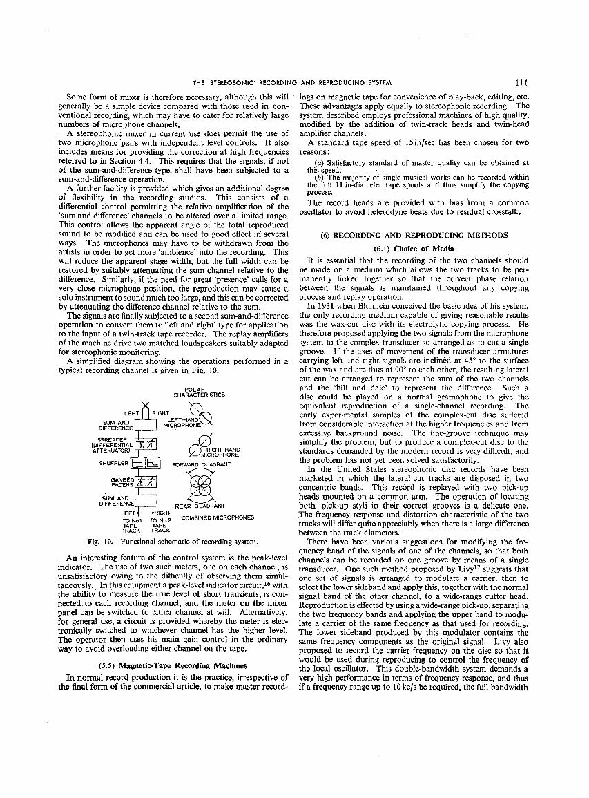
Some form of mixer is therefore necessary, although this will ings on magnetic tape for convenience of play-back, editing, etc.generally be a simple device compared with those used in con- These advantages apply equally to stereophonic recording. Theventional recording, which may have to cater for relatively large system described employs professional machines of high quality,numbers of microphone channels, modified by tho addition of twin-track heads and twin-head
A stereophonic mixer in current use does permit the use of amplifier channels.two microphone pairs with independent level controls. It also A standard tape speed of 15 in/sec has been chosen for twoincludes means for providing the correction at high frequencies reasons:
referred to in Section 4.4. This requires that the signals, if not (a) Satisfactory standard of master quality can be obtained atof the sum-and-difference type, shall have been subjected to a this speed.sum-and-difference operation. (b) The majority of single musical works can be recorded within
A ............... : ...... :._._ .. k:_k ' a- adclltinna 1degree the full II in-diameter tape spools and thus simplify the copyingtUrLIIC[ lactttty 1_ IJiuvlugu Will.It giVeS ........... process.
of flexibility in the recording studios. This consists of adifferential control permitting the relative amplification of the The record heads are provided with bias i_rom a common'sum and difference' channels to be altered over a limited range, oscillator to avoid heterodyne beats due to-residual crosstalk.This control allows the apparent angle of the total reproducedsound to be modified and can be used to good effect in several (6) RECORDING AND REPRODUCING METHODSways. The microphones may have to be withdrawn from theartists in order to get more 'ambience' into the recording. This (6. I) Choice of Mediawill reduce the apparent stage width, but the full width can be It is essential that the recording of the two channels Shouldrestored by suitably attenuating the sum channel relative to the be made on a medium which allows the two tracks to be per-difference. Similarly, if the need for great 'presenc e' calls for a manently linked together so that the correct phase relationvery close microphone position, the reproduction may cause a between the signals is maintained throughout any copyingsolo instrument to sound much too large, and this can be corrected process and replay operation.by attenuating the difference channel relative to the sum. In 1931 when Blumlein conceived the basic idea of his system,
The signals are finally subjected to a second sum-and-difference the only recording medium capable of giving reasonable resultsoperation to convert them to 'left and right' type for application was the wax-cut disc with its electrolytic copying process. Heto the input of a twin-track tape recorder. The replay amplifiers therefore proposed applying the two signals from the microphoneof the machine drive two matched loudspeakers suitably adapted system to the complex transducer so arranged as to cut a singlefor stereophonic monitoring, groove. If the axes of movement of the transducer armatures
A simplified diagram showing the operations performed in a carrying left and right signals are inclined at 45° to the surfacetypical recording channel is given in Fig. 10. of the wax and are thus at 90° to each other, the resulting lateral
cut can be arranged to represent the sum of the two channelsPOLAR and the 'hill and dale' to represent the difference. Such a
CHARACTERISTICS disc could be played on a normal gramophone to give the
_ equivalent reproduction of a single-channelrecording. TheLEFT RIGHT _ early experimental samples of the complex-cut disc sufferedSUM AND [ -I LEFT-HANDk '_J
J 'MICROPHONE vx. from considerable interaction at the higher frequencies and fromOIFFERENCEL-- / excessive background noise. The fine-groove technique may
SPREADERE -- _ simplify the problem, but to produce a complex-cut disc to the(DIFFERENTIAL| ,_._
ATTENUATOR)L -- (/_RIGHT-HAND standards demanded by the modern record is very difficult, and-- )<-JMICROPHONE
SHUF'FLER iL '_?._ _RWARDQUADRANT the problem has not yet been solved satisfactorily.
.._ In the United States stereophonic disc records have been
GANGED_ marketed in which the lateral-cut tracks are disposed in twoFADERSL-__Ly concentric bands. This record is replayed with two pick-up
5OM AND -- heads mounted on a common arm. The operation of locatingDIFFERENCE · REARQUADRANT both pick-up styli in their correct grooves is a delicate one.
LEF1 IGHT .The frequency response and distortion characteristic of the twoTO No.1 TO No.2 COMBINED MICROPHONESTAPE TAPE tracks will differ quite appreciably when there is a large differencemACK TRACK between the track diameters.
Fig. 10._Functional schematic of recording system. There have been various suggestions for modifying the fre-quency band of the signals of one of the channels, so that both
An interesting feature of the control system is the peak-level channels can be recorded on one groove by means of a singleindicator. The use of two such meters, one on each channel, is transducer. One such method proposed by Livy 17suggests thatunsatisfactory owing to the difficulty of observing them simul- one set of signals is arranged to modulate a carrier, then totaneously. In this equipment a peak-level indicator circuit, 16with select the lower sideband and apply this, together with the normalthe ability to measure the true level of short transients, is con- signal band of the other channel, to a wide-range cutter head.nected, to each recording channel, and the meter on the mixer Reproduction is effected by using a wide-range pick-up, separatingpanel can be switched to either channel at will. Alternatively, the two frequency bands and applying the upper band to modu-for general use, a circuit is provided whereby the meter is elec- late a carrier of the same frequency as that used for recording.tronically switched to whichever channel has the higher level. The lower sideband produced by this modulator contains theThe operator then uses his main gain control in the ordinary same frequency components as the original signal. Livy alsoway to avoid overloading either channel on the tape. proposed to record the carrier frequency on the disc so that it
would b, used during reproducing to control the frequency of(5.5) Magnetic-Tape Recording Machines the local oscillator. This double-bandwidth system demands a
In normal record production it is the practice, irrespective of very high performance in terms of frequency response, and thusthe final form of the commercial article, to make master record- if a frequency range up to 10 kc/s be required, the full bandwidth

112 H.A.M. CLARK,G. F.DUTTONANDP.B. VANDERLYN
of the system will be at least 20kc/s. This wide bandwidth is track and shall carry the recording for the left-hand channel asvery difficult to attain, particularly at the inner groove diameters, viewedfrom the audience. The bottom track shall be designated
If recordings are made side by side on a continuous film, the No. 2 D'ackand shall carry the recording of the right-hand channel.synchronization problems are largely overcome, and while it The replay response characteristic (100microsec) and theis recognized that optical methods have been used, the recent track dimensions are in accordance with Amendment No. 1 todevelopment of the magnetic-tape process makes· it a more B.S. 1568: 1953, relating to tape speeds of 7½in/sec. The trackattractivesystem, dimensionsareas showninFig.11.(6.1.1) Crosstalk.
IN-LINE HEADS IN-LINE HEADS
The overallcrosstaikbetweenchannelsshould be better than I .... I ' ._J_9'mo"30dB at all frequencies; In the production of a commercial · _ -
lIGHT-HANDY I/////ARIGNT'HAND .] 91
tape i'ecord there are at least four stages where crosstalk can s?AA..KF?.._[ .I//////[x..SPEAKEI_._ OV
Master recording. EFT-HAND_//////,/,][LEFT-HAND?] o. [,.
Master replay. SPEAKER,,iY [///////XSPEAKffBt
Copy recording, commercial tape record. _') (b) o'o--C_Copy replay.If copy masters are used two more stages of crosstalk are DIRECTIONOF _OTION
introduced. In practice, it has been found that the same amount Fig. ll.--Track standards.of crosstalk is introduced during the recording.process as during (_)Redord-headtrack.
(b) Replay-head track.
the reproducing process. Views looking on coated side of tape.
In well-designed heads a crosstalk of --50 dB can be attained,
and if the crosstalk at the various copying stages can be added (6.3) General Requirements for Domestic Operationarithmetically the overall figure for a commercial tape recordwill be.--38dB, or if a copy master is used, --34dB. If it is .The tape transport mechanism may be of the conventionalrequired to replay either twin-track or single-channel half-track type, but the associated twin-track magnetic replay head ·musttape records from the same head system, the cr0sstalk of this conform to the standards laid down above. Since the signalsreplay head must be better than --55 dB, and preferably ·better from the two tracks on the tape are left and right, it is essentialthan-60dB, in the 1000-3 000 c/s region, that the gains of the two replay channels should be closely
Crosstalk can take place 'owing tq the mutual inductance of matched, and for this purpose'preset controls should be providedthe heads and owing to leakage fields from one track to the for initial adjustment. It is a furtherrequirement that thehead on the other track. The mutual inductance can be reduced equality of gain should be maintained for all settings of the.mainby placing magnetic screens between the heads and separated coupled gain control. Large relative phase shifts in the twofrom them by brass or aluminium spacers. These screens should channels should be avoided, particularly at low frequencies.be large enough to shield the magnetic circuit and the windings. The underlying principle of the system demands that the loud-The usual back gap should be eliminated, and the head dimension speakers should possess, as far as possible, uniform polar response:shouldbe kept as small as possible, characteristics in the horizontal plane at all frequencies. It has.
A useful reduction of cwsstalk can be achieved by either been suggested that departure from uniformity can be anseries or parallel Cross-connection of the windings, so that a advantage in maintaining the apparent position of the sourcesmall signal from·one head is injected in anti-phase to the leakage for a wide range of listening positions. Such non-uniform polar ·signal on the other head. If carefully adjusted the series cross:, characteristics cannot reasonably be attained except at highconnection can reduce the residual crosstalk byat least 10dB. frequencies. Even if it were possible to extend the directional
characteristics ·down to the low frequencies, the beneficial resultsAppreciable crosstalk may occur ff the front edge of the outermagnetic screening shield is too close to the magnetic tape. The claimed would not be realized on account of the path differences,flux from.one track enters the shield and then passes to the 'as outlined in Section 4.5.1. At the high frequencies non-magnetic yoke of the other head operating on the other track, uniform polar characteristics have the disadvantage that theA clearance between the tape and the shield of 0-2 in is sufficient overall tonal balance will vary with the listener's position.to avoid this effect. · Furthermore, the directional response will emphasi.ze any back,
ground hiss and will tend to identify the two loudspeakers as· (6.2) Track Standards separate sound sources and thus'interfere with the illusion. In
The early experimental stereophonic magnetic-tape recordings addition, the domestic user might have difficulty in positioningwere made with the heads displaced by 2_-_in. This enabled the loudspeakers with sufficient accuracy..the conventional half-track heads to be-used on the existing If cone loudspeakers are used the rear radiation should borecording and replay machines, and the separation between the suppressed, and this can be conveniently done by using a closedheads was sufficient to make crosstalk negligible. When copy box baffle. Such baffles can have quite small volume, and theytapes were made for issue as commercial r.ecords it was soon can be designed to occupy a very small floor area. Any loss ofobvious that the use of in-line heads' would make for easier bass response due to the small enclosed volume can be com-acceptanc e as an international standard for domestic and corn- pensated electrically in the power amplifiers.mercial tape records. It was also decided to change to in-lineheads on the master recordings, so that the process of editing (6.3.1) A Commercial Model.was simplified. Furthermore, the use of in-line heads eliminates One form of domestic reproducer has been described byphase shift between the signals On the two tracks owing to small ' Smith and Martin, is but for the sake of completeness a briefvariations of elasticity of the tape along its length.-, general description may be of interest. The complete machine
Standardization has been effected on the designation of the consists of two consoles each containing a loudspeaker grouptracks,whichis as follows: and a poweramplifier. One of these consolesalso contains a
If the tape moves from left to right and with the active side facing tape deck with its associated head amplifiers, ,tone and gainaway from the observer the_top track shall be designated No. 1 controls. Fig. 12 is a schematic. Bass and treble ganged tono

THE 'STEREOSONIC' RECORDING AND REPRODUCING SYSTEM 113
·all other types of record, they are balanced primarily for domestic__,,,, ,.-UNe _ y'_ conditions.
.EAos _/ The most serious errors are caused by increased path
I_/ differences. These occur, as outlined in Section 4.5, down to
'_ l°Wer frequencies and °ver a much greater pr°p°rti°n °f thePRE-,XMVUF_CRS listening area than is the case when operating at the scale forEOUAUZERS which the system was designed.
[5_ [q-] In a small room reflections from the walls, etc., decay rapidly[7'] 1_ GANGED' and follow each other at such short intervals that the resulting__-__J rOUECONTROL sounds appear to the listener to coalesce. In large halls thejr__r_ GAUC,_n relatively undamped primary reflections from the surroundings
VoLuM'E-¥(SNTROL arrive at the listeners' ears at intervals sufficiently great to cause--r'- -T--DIFFERENTIALNTROL an appreciable distortion of the sound picture.
r--m _ L-_o Ideally the system requires that the' loudspeakers shall be
L,F LOUDSPEAKgR_OWE R __ uniformly radiating point sources. In the domestic case aHF. LOUDSPEAKERt::;;:::3'2--J ,M_;"i_i_-RS_ reasonable approximation tO this can be achieved because single
Fig. 12.'Functional schematic of reproducer, small units can be constructed to 'handle the required power.In large-scale reproduction, multiple units or single 'units of
controls are provided, in order to allow some adjustment for the appreciable size are necessary; this departure from the idealdifferent acoustic conditions which may be met. can cause a depreciation of the stereophonic definition.
In order to maintain uniformity between the two channels thecontrols are of the stepped-switch type. The main gain control (7) ACKNOWLEDGMENTS.consists of two ganged switches with 12 steps of 3dB each. The authors wish to acknowledge the assistance of manyTherq is a differential gain control on the panel to take uP any members of the technical staff at the Recording Studios and'theslight drift in amplifier gains and to allow for asymmetry in the Research Laboratories of Electric and Musical Industries, Ltd.,listening room. A preset continuous control on the amplifier and Messrs. D. E. Broadbent and B. Shackel for helpful dis-chassis balances the gain during factory adjustment. The power cussion on the physiology of hearing.amplifiers are rated at a peak output level of 10 _vatts. They also wish to thank the Directors of Electric and Musical
In order to give the best horizontal polar distribution the Industries, Ltd., for permission to publish the paper.elliptical cone loudspeakers are mounted in closed rigid boxbafflesof 3½ft3capacity, the major axis of the cone ellipse being (8) REFERENCESvertical. The frequency range of this speake r is limited at the (1) 'The Telephone at the Paris Opera', Scientific American,upper end to about 5000c/s, in which region the electrostatic 31st December, 1881.speaker takes over and continues beyond 15kc/s. The electro- (2) BLUMLeIN,A. D.: British Patent No. 394325.static speaker consists of a curved metal back plate 24in long (3) FLeTCHeR, H., et al.: 'Auditory Perspective', Bell Systemby 1¼in wide, over which is laid a membrane metallized on the Technical Journal, 1934, 13, p. 239.side away from the back plate. This speaker isdriven from a (4) Load RAYL£Xga:'Theory of Sound, Vol. II', p. 42[0.separate amplifier and is supplied with a bias potential of (5) SXEW^RX,G. W.:'Binaural Location of Pure Tones--I300 volts, and II', Physical Review, 1920, 15, p. 425.
(6.3.2) Domestic Listening Conditions. (6) Bt_Nxsxfia,H.: 'The Basis of Sound Localization' (PhysicalSociety Discussion on Audition, June, 1931).In general, 'stereosonic' tape record s are balanced with regard (7) 'Studies in the Localization of Sound' (Medical Research
to tonal quality and perspective, for reproduction in the average Council Report, 1932).home lounge in which the reverberation time is of the order of (8) S^NDEL, T. T., TEas, D, C., FEDr>EaS_N,W. F., and0.5 sec or less. This reverberation period is short compared J£VFRESS,L. A.: 'Localization of Sound from Single andwith that in the studio or Concert hall in which the record- Paired Sources', Journal of the Acoustical Society ofings will have been made; .it is not likely to interfere with the .America, 1955, 27, p. 842.listener's impression of the original Studio conveyed to him by (9) GALAMBOS,R., and DAWS, H_: 'The Response of Singlethe stereophonic effect; and there will be no confusion due to Auditory Nerve Fibres to Acoustic Stimulation', Journalthe two distinct reverberations which might blur the detail, of Neurophysiology, 1943, 6, p. 39.Provided that the walls and thefloor are reasonably absorbent (I0) JEvFa_ss, L. A.: 'A Place Theory of Sound Localization',it is found that, in spite of errors due to asymmetry, one can Journal of ComparativePhysiological Psychology, 1948,move about over a large floor area in front of the loudspeakers 41, p. 35.'without losing the major benefits of this type of reproduction. (11) ROSENZWEm, M. R.: 'Cortical Correlates of AuditoryAs stated earlier in the paper, the optimum position for listening Localization and of Related Perceptical Phenomena',is at the apex of an equilateral triangle with the base-line formed ibid., 1954.by the line joining the two loudspeakers; this is the arrangement (12) FmesxoNe, F. A.: 'The Phase _Difference and Amplitudeused for monitoring during recording. In the average room it is Ratio at the Ears Due to a Source of:Pure Tone', Journalsatisfactory to set the loudspeakers 10 or 12ft apart, but in a of the Acoustical Society of America, 1930,'2, p. 260.restricted space a very fair performance can be obtained down (13) SXVIAN,L. J., and Wmxe, S. D.: 'Minimum Audible Soundto distances of as little as 4 or 5ft. Fields', ibid., 1933, 4, p. 288.
(6.4) Operation of the System in Large Halls (14) V^NDm_X_Y_4,P. B.: British Patent Application No. 23989,1954.Special difficulties attend the reproduction of 'stereosonic' (15) De BOER,K.: 'Stereophonic Sound Reproduction', Philips
r_cords on a large scale, apart from the general fact that, like TechnicalReview, 1940, 5, p. 107.
114 H.A.M. CLARK,G. F.DUTTONANDP.B. VANDERLYN
(16) TERRY, M. T.: British Patent Application No. 12839, 1956. Yt = Fractional distance of real source from central(17) Livy, W. H.: BritishPatent No. 612163,1946. position.(18) MART_N,M. B., and SMITH,D. L. A.: 'The Design of L, R = l_lagnitudes 0fsound i_ressures due to WLand WR
Magnetic RecOrding and Reproducing Equipment for at C.Domestic Use', Journal of the British b_stitutionof Radio' /_,y = Angles subtended at listener by Wl. and WR.Engineers, 1956, 16, p. 65. r = Difference in time of arrival of sounds from WL
and WR at O due to path difference.
(9) APPENDIX bt/.,/da = Time differences at ears EL and ER relative to Oof sounds from Wi. and WR.
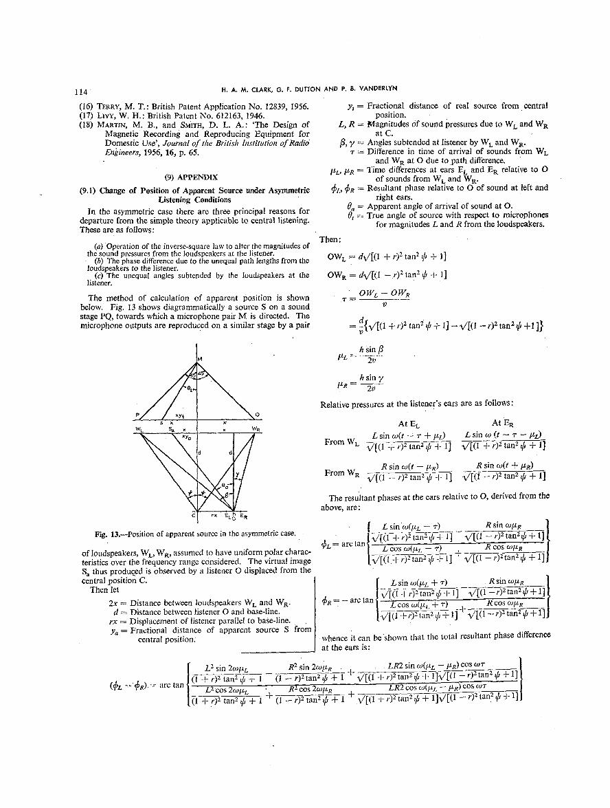
(9.1) Change of Position of Apparent Source under Asymmetric _/., _R = Resultant phase relative to O of sound at left andListening Conditions right ears.
In the asymmetric case there are three principal reasons for 0a = Apparent angle of arrival of sound at O.departure from the simple theory applicable to central listening. Ot= True angle of source with respect to microphonesThese are as follows: for magnitudes L and R from the loudspeakers.
Then:(a) Operation of the inverse-square lawto alter the magnitudes of
the sound pressures from the loudspeakers at the listener. OWl, = d%/[(1 470 2 tan2 ¢ -}- 1]· (b) The phase differencedue to the unequal path lengthsfrom th8loudspeakers to the listener.
(c) The unequal angles subtended by the loudspeakers at the OWR -----d%/[(l - 0 2tan 2 _b+ 1]listener.
O_L--OWRThe method of calculation of apparent position is shown ._--below. Fig. 13 shows diagrammatically a source S on a sound vstage PQ, towards which a microphone pair M is directed. Tho
microphone outputs are reproduced on a similar stage by a pair = d{%/[(1 + r)2tan 2 _b+ 1] -- ¥/[(1 -- r)2tan 2 _b+11}
h sin pbtz,.... ).T"
/zR = 20
.. Relativepressuresat thelistener'searsare asfollows:
wc s s_, _ { _ w. At Et, At ER...... L sin co(t -_ r + btz) L sin co(t -- _' --/dr)
· xyQ Fr°mWL %/[(l+r)2tan2_b+l] %/[(l+r)2tan2_b+l]d d
R sin co(t --/dR) R sin co(t +/dR)
FromW R %/[(1--r) 2tan 2_b+l] %/[(1--r) 2tan 2_b+l]
The resultant phases at the ears relative to O, derived from th,above, are:
[ L sin'co(brL-: r) R sin co/dR IFig. 13.--Position of apparent source in the asymmetriccase. · . J _7[_ + r)2 tan 2_b'4-1] - %/[(1 '_'_ t"a-nS-_b+ 1]
of loudspeakers, Wi., WR, assumed to have uniform polar charac- (3L= arc tan j L cos co(Fa -- r) R cos co/dR Jteristics over the frequency range considered. The virtual image [_1.---_-_ ta-fi5 _ 1] + %/[(1 -- 0 2tan2 _b+ 1]]Sa thus produced is observed by a listener O displaced from the
central position C. [ L sin co(/dL+ z) R sin co/d.e _] [J
Then let J %/[O _-;-)_tm-12_b-TF1] %/[(1-- r)2tan2_b+ I ]
2x = Distance between loudspeakers Wi. and WR. _R = - arc tan j L cos co(/zL+ r) . R cos co/ded = Distance between listener O and base-line.rx = Displacement of listener parallel to base-line. [%/[(1 + r)2tan2¢ + _-t- %/[(1-- r)2tan 2_b+Ya= FractiOnal distance of apparent source S from
central position: whence it Can be shown that the total resultant phase differenceat the ears is:
L2 sin 2co/dL R2sin 20J/Z R , LR2 sin CO(?'L -- /dR) COS _tOT - J
(_r '- (_R)= arc tan (1 47r_ 2 tan 2 _b+ 1 -- (l -- r)2t_+ ]-v %/[(f +-r)-T_n_,_]%/[(l _ r)2tan2 ¢ + !][L2cos 2co/d c _ R2cos 2co/dR __ LR2 cos co(/dz_/dh) cos co0- /

THE 'STEREOSONIC'RECORDINGAND REPRODUCINGSYSTEM 115
Making the approximation, on which the system is based, that co/zL and w/LR are small, thus implying also that _L and _Rare small:
/(_£ _ _R) .._>tan (_L _ _). + (1 + r)2 tan2_ b+l (1-r)2tan2_b+l+_/[(l+r)2tan2_b+l]_/[(1-r)2tan2_b+llL2 R 2 LR2 cos w_-
(1 q- r)2 tan2 _b+ 1 + (1 - r)2 tan2 _b+ 1 + _/[(1 + r)5 tan2 _b-¢ 1]_/[(1 - r)2 tan2 _b-k'i]]
wh sin 0aBut (_z,-- _R)= ,/)
Substituting for/z L and/x R in the expression for (gL -- _R):
I (LJR) sin j_ (RJL) sin r (sin/_ -- sin y) cos co, J
0_=arcsin (1 +r) 2tan 2_b+l-(l--r) 2t_4-1 -_ x/i(1 +r) 2tan 2_b_l]_/[(1-r) 2tan 2_+1]LJR RJL 2coscot
(1 + r)2 tan 2_b + 1 + (1 _ t_ _ 1 + V'[(I + r)2 tan 2 _b+ 1]_/[(l -- r)2 tan 2_b + 1]
The fractional distance of the apparent source from the central position is then given by
dtan0, tan0_· r -- /'Ya -- x tan _b
Similarly, the fractional distance of the real source from the central position before the microphones is given by
tan Ot _ fan 0 tYt -- tan 45 °
45 ° being half the working angle of the microphones.
DISCUSSION BEFORE THE RADIO AND TELECOMMUNICATION SECTION, 20TH FEBRUARY, 1957
Mr. J. Moir: I am professionally interested in the repro- recordings I am not so enthusiastic about the authors' explana-duction of sound films in which three-channel stereophonic tion of how the system works. They suggest that their two~reproducer systems are common, but I have an interest in channel system gives stereophonic results because it allows thedomestic stereophonic systems as an enthusiastic amateur, brain to compare the amplitude of the signals at the two ears,
I have been playing these stereosonic magnetic-tape recordings the signal at.each ear being the vector sum of signals reachingfor some months, and my only comment on their performance the ear from both loudspeakers. They support this suggestionis that the authors have understated the advantages. The spatial with an elegant mathematical analysis in which I can find nodistribution and the impression of size that a good stereophonic questionable step, but in spite of this, I do not believe that thesystem gives to an orchestra is most effective and most important, stereophonic results can be explained in this way or so simply.The individual instruments and sections of the orchestra are A source emitting a single sound pulse in the studio will resultclearly separated, which gives a degree of clarity and definition in two pulses reaching each ear, but I would suggest that onlyto the performance that cannot be obtained from a monaural the first pulse at each ear reaches the brain. The nervous systemsystem, however much the amplitude distortions are reduced, transmits amplitude indications as a pulse code, pulse-repetitionA monaural system with 0' 5% distortion does not sound so rate being related to sound intensity. However, the maximum'clean' as a stereophonic system with 5 % distortion, pulse rate cannot exceed 1000 pulses/sec, while 300-500 pulses/sec
It has been appreciated for the last 25 years that the public is the more usual maximum. This pulse-rate limitation iswill not accept a reproduction of an orchestra with the full imposed by the maximum rate at which the transmitting-end cellsoriginal' frequency range or volume range. Many reasons have can be chemically recharged by the blood stream. Thus, after abeen advanced, all with some degree of truth, but there is no discharge, the nerve cannot transmit a second signal for a timedoubt that the use of monaural reproducer systems is a major which is always greater than 1millisec. However, the headfactor in this preference for range restriction, dimensions are such that the second acoustic pulse will appear
It has often been said that the advantages of a stereophonic from the remote loudspeaker with a time interval which is always
system are too subtle for the ordinary members of the public to less than 0-6 millisec. At first sight, it would appear that noappreciate, but my experience tends to the opposite point of stereophonic effects could be produced if the sound source emittedview. Fifteen or twenty of my friends have heard these stereo- short pulses, though in fact the stereophonic effect is most
phonic tapes run on my domestic equipment and have had the marked.opportunity of making an immediate comparison with a long- Our own work indicates that there are clues to source positionplaying recording of the same work run monaurally. After distributed over the whole of the audio-frequency range thoughabout ten seconds of monaural reproduction the invariable the majority of the information is contained in the frequencycomment is on the flatness, range above 500 cJs.
Though I am fairly enthusiastic about these stereophonic Dr. E. C. Cherry: During the course of a recent informal

116 H.A.M. CLARK,O. F.DUTTONANDP. B.VANDERLYN
meeting* I expressed the opinion that stereophony, using two- conductor endeavour to produce a good effect at, say, the middleloudspeaker systems, is impossible. In view of the authors' of the hall, or is he the only person really hearing the music asdemonstration, it seems behoven upon me to explain myself it should be heard?further. In usingthe systemfor producingrecordingsin the home,
I repeat that it is impossible, but the practice of engineering should the listener be virtually transferred from a position in thecontinually involves the solution of impossible tasks; it is a auditorium to the conductor's rostrum, or should the aim beregular search for compromise. In the present context, the to 'seat' him effectively in a position, say, centrally five rowstheoretical impossibility arises from several reasons, not the from the front?least important being that the acoustic environments in the · Major W. V. G. Fuge: In the demonstration with two peoplerecording studio and in the home or concert hall are simply not speaking at the same time and recorded stereophonically, itreciprocal. Why, it may be pertinent to ask, did the demon- seemed possible to listen at will to either conversation by mentallystration take place in the Great Hall of Northampton Polytechnic concentrating without moving the head, so that a mental Processand not, more conventionally, in the Lecture Theatre? Again, could switch the attention from one voice to the other.the acoustic conditions may be adjusted to some extent, but they Is that the advantage of the stereophonic recording, i.e. thatcannot be suitable for all listening situations; neither can the different people listening to the same music can concentrate onlistener be free to move far from a centre-line or other given any particular instrument they wish from time to time andcontour without the apparent directive qualities vanishing, switch their attention to what pleases them?
The binaural directive location of a sound, in real-life environ- Mr. F. Oakes: Mr. Thornton asked whether the stereosonicments, is not yet understood; more fundamentally, the psycho- recording should reproduce what the conductor hears from thelogical 'projection' of sounds to lie 'outside' our heads is not rostrum. The answer is in the negative, because the balance ofunderstood, nor are the physical controlling factors. Binaural instruments is adjusted during rehearsal to provide the correctphase (time) difference and amplitude difference, by themselves, sound in the auditorium. Depending on the acoustic propertiesdo not account for such projection and angular discrimination, of the concert hall, this may well mean that what the conductor
The brain makes great use of the differences between the hears is far from acceptable, whilst correct placement of thesignals reaching the two ear portals, and there are several microphones further from the orchestra will produce a satis-differences other than time and amplitude (e.g. effects of room factory balance, such as would be enjoyed from a good seat inacoustics and the listener's experience of typical environment the auditorium.effects; head-turning effects; head diffraction; the varied angle Mr. J. K. Webb: To anyone who has been privileged to hearof arrival of wavefronts, and impedance mismatch at the ear a demonstration of the authors' stereosonic reproducing systemportals). I agree with Mr. Moir that Fourier-type analysis, and in an average-size living room, 'revelation' is about the onlytheory such as that given in the paper, are best laid aside when word adequately to describe it. This scheme is surely a mutationtrying to understand stereophonic hearing. Statistical analysis which is bound to set a completely new standard and inevitablyrather than Fourier analysis may be the brain's function, expose the deficiencies of 'monosonic' recording.
My remarks do not purport tobe disparaging in the least, but It must always be borne in mind, when considering domesticI wish merely to stress the need for much more psycho-physical sound reproduction, that one cannot contemplate the enormousstudy, not only of binaural hearing, but of other sensory functions range of sound levels with which the authors have battered ourin communication. Perhaps then we may understand results eardrums in their demonstration, however commendable thissuch as those which were so well demonstrated by the authors, may be from the technical angle. Let it be said in praise of
Mr. G. Millington: In the early days of electrical recording I music in the home, as it was of Cordelia, 'Her voice was everdid some work under Mr. P. W. Willans on high-fidelity recording soft, gentle and low--an excellent thing in woman'. To circum-of the piano. We found that, with a single microphone in a vent the Fletcher-Munson effect and otherwise wrest the maxiXfixed position, it was extremely difficult to avoid an uneven mum satisfaction from a limited range of loudness is a problemresponse in which some notes had a dully wooden sound while which perhaps merits more attention than it has so far been given.others were unnaturally brilliant. When one note was cured by Mr. R. Vermeulen (Netherlands: communicated): There canmoving the position of the microphone, it was usually at the be no doubt about the benefit, nay the necessity, of stereophony,expense of another in a different part of the register, if one really wants a life-like reproduction and not just 'hi-fi'.
I should like to ask the authors whether the placing of the By its very nature, even the most perfect loudspeaker cannotmicrophone system is similarly critical when using two micro- possibly be any better than a hole of the same dimensions in thephones at the same position but orientated ill different directions, wall of the concert hall. It is still something of a miracle thatAs far as I could tell, the recording given was perfect in this this 'hole can be enlarged into a wide window frame by meansrespect, and was as fine an example of piano recording as I of only two loudspeakers, but we have to accept this as ahaveheard, fact.
Mr. A. M. Thornton: ! assume that the system is intended to Such a window seat would not be considered quite satisfactoryhave a great future in high-quality and more realistic recording, in the concert hall. What we really want is a seat right in theand that ultimately we shall have this sort of stereophonic quality middle of the hall. Therefore, though 1 agree that at presentin our homes, and for mostpracticalpurposes'the reproductioncan be limited
In the case of the single instrument--the piano--the qual!ty to sounds arriving from directions covering an angle of, say,and fidelity were the most satisfying that I have experienced, but 90° in front of the observer', I do not consider this to be the finalwhen it came to the orchestral item 'Peter and the Wolf' I was solution of perfect music reproduction, but expect a still furthervery disconcerted. The notes alternated from one side of the development.stage to the other exactly like the sound of the ping-pong ball It is true that we can imitate the orchestra itself by stereophonicin the table-tennis game previously demonstrated. I realized methods, but this imitation orchestra, like the real one, will onlythen that that is how the conductor must hear the music, i.e. quite sound well in a hall with good acoustics and not in a room withdifferently from the vast majority of the audience who are sitting poor acoustics or in the home. In order to have a completelysome distance away. This raises the interesting point: Does the life-like reproduction it is necessary also to simulate the sound* 'ThePsychologyofCommunication',JournalLE.E.,1957,3, (New Series), p. 209. waves reflected from the ceiling and from the walls of the concert
THE 'STEREOSONIC' RECORDING AND REPRODUCING SYSTEM 11 7
hall. These are not limited to an angle of 90°, but they come the authors have reduced the intensity differences of the loud-from all sides, and it is essential that they do so. The reverberant speakers to phase differences at the ear of the listener, but I stillsound must not only have the right reverberation time; it must have some doubt whether binaural hearing can be explained byalso have the right diffuseness, only one single principle. Phase differences with pure tones are
It is possible to simulate such a diffuse reverberation artificially not equivalent to differences in time of arrival of clicks, and Iby placing loudspeakers all round the auditorium and feeding cannot see, at present, how the precedence effect, for instance,them with suitably delayed music, using several different time can be fitted to the authors' theory. Moreover, there is somedelays. By adding such a stereo-reverberation to the stereo- experimental evidence that differences of intensity at the ear ofphonic reproduction, a completely life-like reproduction can be the listener cannot altogether be neglected. I am not yet com-obtained, pletelyconvincedthat it will be wiseto base our techniqueson
I am impressed by the elegant and convincing way in which a single effect only.
THE AUTHORS' REPLY TO THE ABOVE DISCUSSION
Mr. H. A. M. Clark, Dr. G. F. Dutton, and Mr. P. B. the first operation performed on a sound when it reaches theVanderlyn (in reply): As Mr. Moir states, it is agreed that direc- human cochlea is a Fourier analysis.tional clues of various kinds occur at all audible frequencies, In reply to Mr. Millington, the use of a double microphoneand their relative importance must vary to some extent with the driving two separate loudspeaker channels does largely avoid thespectral content of the sounds with which a system is concerned, unevenness in tonal quality in some parts of the register causedIn the present case, wftere the reproduction of music is the chief by standing waves in the studio.aim, it is c0nt_nded that low frequencies play at least as important Mr. Thornton dislikes the alternation of sounds between onea part as high frequencies. In the design of a stereophonic side of the stage and the other. Although this is certainly whatsystem, due regard must be p_tid to the types of clue capable of the conductor hears there was no intention to give a reproducedreproduction within the physical and economic framework, and performance from this viewpoint. The arrangement of theif any are found to be mutually exclusive, a choice must be made demonstration was intended to convey the impression of anas to which to reject. In the case of the stereosonic system, it orchestra occupying the full area of the stage. It is contendedwas decided to exclude the 'precedence' clue, since to reproduce that such an impression would be realistic, but if a domesticit would necessitate specification of the precise listening posi- user feels that the reproduction is on too large a scale dimen-tion to be adopted, from which the observer would not be sionally, it is always open to him to reduce the distance betweenallowed to move. For this reason, the system will not deal his loudspeakers.correctly with the case cited by Mr. Moir, i.e. a single short Major Fuge is correct in supposing that one of the advantagessound pulse. It is fair to say, however, that naturally occurring claimed for the system is an increased freedom for selectivesingle sound pulses are infrequent, and analysis of most sounds listening to a particular part of the recorded sound.of short duration reveals them to be composed of many cycles Mr. Webb raises the difficult question of domestic sound levels.of pressure variation. For localization, the system, as Mr. Moir It may well be that a sound can be made to appear louder thanstates, allows a comparison of aural amplitudes, but this occurs it really is by controlled juggling with the frequency response ofat high frequencies only; at low frequencies the mechanism of the reproducing channel. The operating range of such a controlvector summation described in the paper permits a phase com- is likely to be limited, however , and many will think that nothingparison, can recreatethe sensationof a reallyloud soundbut reproduction
Many workers in this field of endeavour will at times be at a level comparable with the original. In this respect he is, toinclined to agree with Dr. Cherry's statement that two-channel some extent, at the mercy of the recording engineer, since, ifstereophony with loudspeakers is impossible. Much depends on modern recordings are not permitted to reach reasonably highthe precise meaning attached to the terms 'stereophony' and levels during reproduction, the quiet passages will be lost in'impossible'. He does not deny, however, that reproduced background noise.sounds having a pronounced spatial character have been demon- Mr. Vermeulen mentions the further application of stereophonystrated, at least to those listeners in the more favoured seats, to include reverberation from the back of a hall. Many of usPerhaps these qualifications may help to illuminate his state- who have not had the good fortune to hear the results of hisment. experimentshave, nevertheless,read about them with interest,
In the engineering basis of the system, nothing is assumed and it may well be that where such means as he describes areabout the way in which the human 'black box' operates, nor is applicable and economically feasible, they will add 'considerablyany such assumption necessary, since all that is attempted is a to the subjective enjoyment of a reproduced performance.reconsti'uction of the acoustic conditions that would obtain at an Finally, in reply to him and to other speakers, it is not our aimobserver's ears were he actually present in the recording studio, to produce a complete theory of binaural hearing, least of allOne requirement for satisfactory reproduction is that the listening to ascribe it to a single mechanism. The stereosonic systemroom should not add appreciably to the total reverberation, and came about as the result of considering what naturally occurringit should be stressed that the system is designed for domestic clues exist, and of attempting to recreate a few of them. Others,use where this is normally the case and where the listener can such as the 'precedence' clue, have had to be rejected. If theoccupy the optimum position. It is not intended for large-scale explanations offered to fit the observed facts are not lookeddemonstration, upon with favour, it can only be remarked that they are not
Before finally rej_ting any explanation, based on Fourier put forward in any spirit of pontification, but that, at least, theyanalysis, of the effects produced, it must be remembered that have the merit of some experimental foundation.