Embed Size (px)
Citation preview

Application & Tools
Answers for industry. Answers for industry.
Deckblatt
Integration and call of Simulink subsystems with STEP 7 and WinAC ODK using PID control as an example
WinAC S2O (Simulink to ODK) Wizard
STEP 7, WinAC ODK
Application February 2012
www.infoPLC.net

2 WinAC S2O Wizard
Version 1.0.1, Entry ID: 56969417
Co
pyr
igh
t S
iem
en
s A
G 2
01
2 A
ll rig
hts
re
serv
ed
Siemens Industry Online Support This article is taken from the Siemens Industry Online Support. The following link takes you directly to the download page of this document:
http://support.automation.siemens.com/WW/view/en/56969417
Caution The functions and solutions described in this article confine themselves to the realization of the automation task predominantly. Please take into account furthermore that corresponding protective measures have to be taken up in the context of Industrial Security when connecting your equipment to other parts of the plant, the enterprise network or the Internet. Further information can be found
under the Content-ID 50203404.
http://support.automation.siemens.com/WW/view/en/50203404
If you have any questions concerning this document please e-mail us to the following address:
mailto:[email protected]
You can also actively use our Technical Forum from the Service & Support Portal regarding this subject. Add your questions, suggestions and problems and discuss them together in our strong forum community:
www.infoPLC.net
WinAC S2O Wizard Version 1.0.1, Entry ID: 56969417 3
Co
pyr
igh
t S
iem
en
s A
G 2
01
2 A
ll rig
hts
re
serv
ed
s
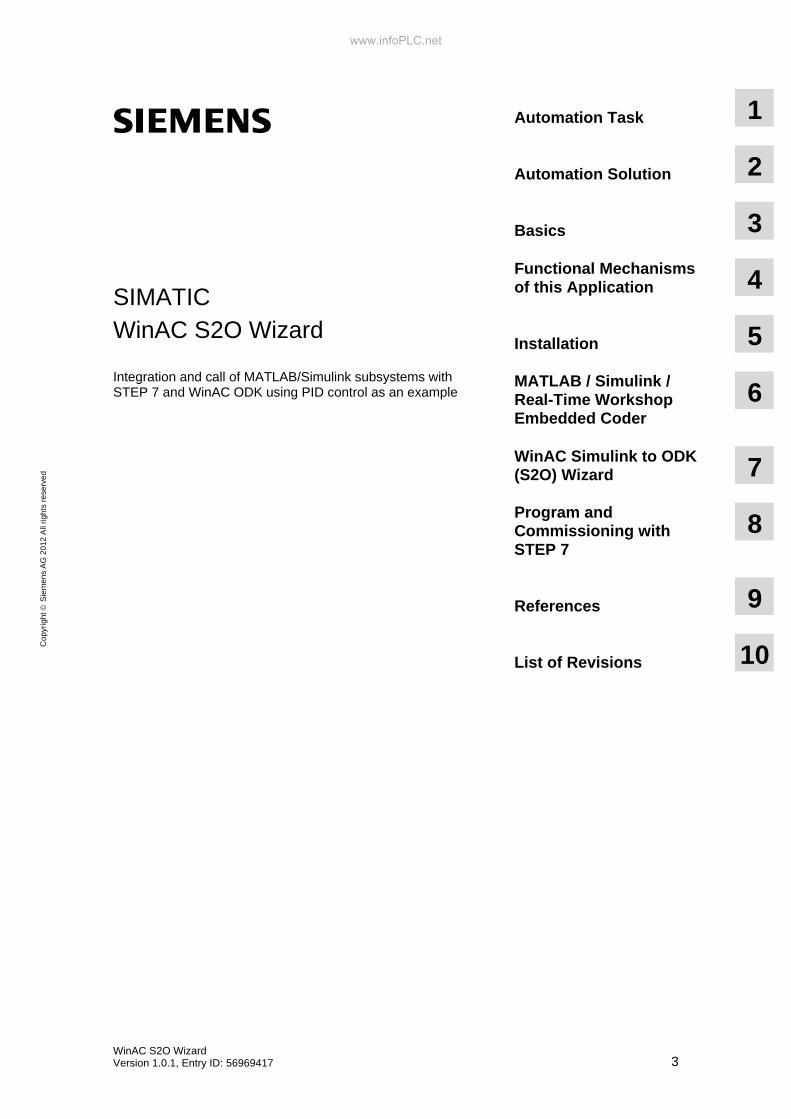
SIMATIC WinAC S2O Wizard
Integration and call of MATLAB/Simulink subsystems with STEP 7 and WinAC ODK using PID control as an example
Automation Task
1
Automation Solution
2
Basics
3 Functional Mechanisms of this Application
4
Installation
5 MATLAB / Simulink / Real-Time Workshop Embedded Coder
6
WinAC Simulink to ODK (S2O) Wizard
7
Program and Commissioning with STEP 7
8
References
9
List of Revisions
10
www.infoPLC.net

Warranty and Liability
4 WinAC S2O Wizard
Version 1.0.1, Entry ID: 56969417
Co
pyr
igh
t S
iem
en
s A
G 2
01
2 A
ll rig
hts
re
serv
ed
Warranty and Liability Note The Application Examples are not binding and do not claim to be complete
regarding the circuits shown, equipping and any eventuality. The Application Examples do not represent customer-specific solutions. They are only intended to provide support for typical applications. You are responsible for ensuring that the described products are used correctly. These application examples do not relieve you of the responsibility to use safe practices in application, installation, operation and maintenance. When using these Application Examples, you recognize that we cannot be made liable for any damage/claims beyond the liability clause described. We reserve the right to make changes to these Application Examples at any time without prior notice. If there are any deviations between the recommendations provided in these application examples and other Siemens publications – e.g. Catalogs – the contents of the other documents have priority.
We do not accept any liability for the information contained in this document.
Any claims against us – based on whatever legal reason – resulting from the use of the examples, information, programs, engineering and performance data etc., described in this Application Example shall be excluded. Such an exclusion shall not apply in the case of mandatory liability, e.g. under the German Product Liability Act (“Produkthaftungsgesetz”), in case of intent, gross negligence, or injury of life, body or health, guarantee for the quality of a product, fraudulent concealment of a deficiency or breach of a condition which goes to the root of the contract (“wesentliche Vertragspflichten”). The damages for a breach of a substantial contractual obligation are, however, limited to the foreseeable damage, typical for the type of contract, except in the event of intent or gross negligence or injury to life, body or health. The above provisions do not imply a change of the burden of proof to your detriment.
Any form of duplication or distribution of these Application Examples or excerpts hereof is prohibited without the expressed consent of Siemens Industry Sector.
www.infoPLC.net

Preface
WinAC S2O Wizard Version 1.0.1, Entry ID: 56969417 5
Co
pyr
igh
t S
iem
en
s A
G 2
01
2 A
ll rig
hts
re
serv
ed
5
696
941
7_
Win
AC
_S
2O_
Wiz
ard
_D
OK
U_
v101
_en
.do
c
Preface Objective of this application
MATLAB/Simulink made by Mathworks is a system modeling and simulation software. The graphical editor of Simulink can be used to create realistic processes and develop solutions, for instance, in the control engineering field. The Real-Time Workshop Embedded Coder (RTWEC) add-on can compile Simulink subsystems directly into the C/C++ code. With the help of WinAC ODK the C/C++ code can be executed in the Windows or real-time environment of WinAC RTX. The WinAC S2O (Simulink to ODK) Wizard supports the user in integrating Simulink subsystems in STEP 7.
Main contents of this application The following main points are discussed in this application: • Creation of a simple block (PID controller) with MATLAB/Simulink • Compilation in C/C++ code with Real-Time Workshop Embedded Coder • Integration into a STEP 7 project with the WinAC S2O Wizard
Topics not covered by this application This application does not include a detailed description of • the control engineering basics • MATLAB/Simulink and Real-Time Workshop Embedded Coder • WinAC RTX and WinAC ODK • IntervalZero • C/C++ programming • STEP 7 programming
Basic knowledge of these topics is required.
Note Mathworks software was used for this application. They changed the names during creation. The previous names were kept in this documentation though because the programming and testing was done with this software.
Alt New
Real-Time Workshop Simulink Coder
Real-Time Workshop Embedded Coder Embedded Coder
www.infoPLC.net

Table of Contents
6 WinAC S2O Wizard
Version 1.0.1, Entry ID: 56969417
Co
pyr
igh
t S
iem
en
s A
G 2
01
2 A
ll rig
hts
re
serv
ed
Table of Contents Warranty and Liability ................................................................................................. 4 Preface .......................................................................................................................... 5 1 Automation Task................................................................................................ 7 2 Automation Solution ......................................................................................... 9
2.1 Overview of the general solution.......................................................... 9 2.2 Hardware and software components used......................................... 14 2.2.1 Hardware components ....................................................................... 14 2.2.2 Software components......................................................................... 14 2.2.3 Sample files and projects ................................................................... 15
3 Basics ............................................................................................................... 16 4 Functional Mechanisms of this Application ................................................. 18
4.1 General overview ............................................................................... 18 4.2 Data types .......................................................................................... 19
5 Installation........................................................................................................ 20 5.1 Hardware installation.......................................................................... 20 5.2 Software installation ........................................................................... 21 5.3 Installing the application software ...................................................... 22 5.4 Installing the Example Files ............................................................... 22
6 MATLAB / Simulink /Real-Time Workshop Embedded Coder..................... 23 6.1 Controller creation and process simulation with
MATLAB/Simulink .............................................................................. 23 6.1.1 The process........................................................................................ 23 6.1.2 The PID controller .............................................................................. 25 6.1.3 Simulation of the complete control loop ............................................. 29 6.2 C/C++ Generation with RTWEC ........................................................ 32
7 WinAC Simulink to ODK (S2O) Wizard.......................................................... 34 8 Program and Commissioning with STEP 7................................................... 37
8.1 Configuration with STEP 7 V5.5......................................................... 37 8.1.1 Programming...................................................................................... 37 8.1.2 Commissioning................................................................................... 41 8.2 Configuration with STEP 7 V11.......................................................... 42 8.2.1 Programming...................................................................................... 42 8.2.2 Commissioning................................................................................... 45
9 References ....................................................................................................... 46 9.1 Bibliographic references..................................................................... 46 9.2 Internet Links...................................................................................... 46
10 History............................................................................................................... 46
www.infoPLC.net
1 Automation Task
2.1 Overview of the general solution
WinAC S2O Wizard Version 1.0.1, Entry ID: 56969417 7
Co
pyr
igh
t S
iem
en
s A
G 2
01
2 A
ll rig
hts
re
serv
ed
1 Automation Task
Requirement MATLAB/Simulink is frequently used in automation and control engineering to simulate processes and create PID controllers. The task is to make created algorithms, functions or systems run on a PLC in few steps. Mathworks provides the option to compile the Simulink subsystems into C/C++ code with Real-Time Workshop Embedded Coder (RTWEC). This code in turn can be integrated into a WinAC ODK project and be called from the STEP 7 program via DLL/RTDLL and be executed.
General task Subsystems created in MATLAB/Simulink shall be ported in WinAC RTX and be executed.
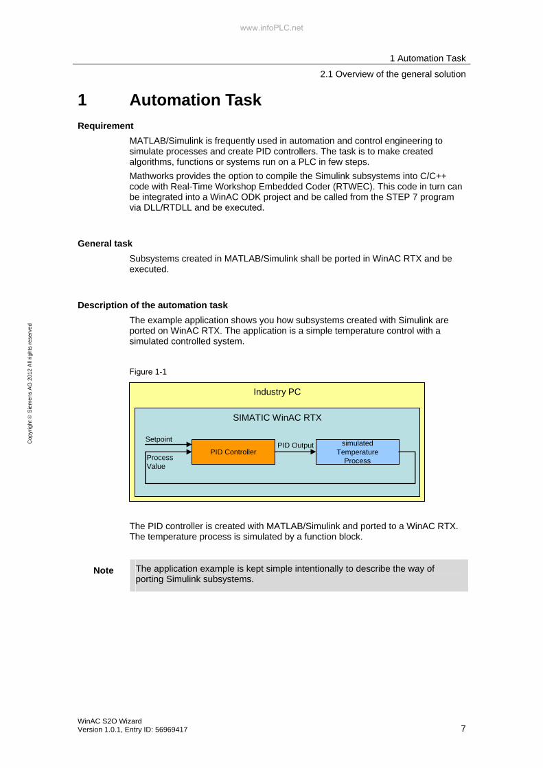
Description of the automation task The example application shows you how subsystems created with Simulink are ported on WinAC RTX. The application is a simple temperature control with a simulated controlled system.
Figure 1-1
Industry PC
SIMATIC WinAC RTX
simulatedTemperature
ProcessPID Controller
SetpointPID Output
ProcessValue
The PID controller is created with MATLAB/Simulink and ported to a WinAC RTX. The temperature process is simulated by a function block.
Note The application example is kept simple intentionally to describe the way of porting Simulink subsystems.
www.infoPLC.net

1 Automation Task
2.1 Overview of the general solution
8 WinAC S2O Wizard
Version 1.0.1, Entry ID: 56969417
Co
pyr
igh
t S
iem
en
s A
G 2
01
2 A
ll rig
hts
re
serv
ed
Teaching material of this application After studying this application, you will be familiar with the following: • example simulation of processes and controller creation in Simulink • example C/C++ coding of a Simulink subsystem with Real-Time Workshop
Embedded Coder • functions of the WinAC S2O Wizard • example procedure of the WinAC ODK project in a WinAC RTX
www.infoPLC.net

2 Automation Solution
2.1 Overview of the general solution
WinAC S2O Wizard Version 1.0.1, Entry ID: 56969417 9
Co
pyr
igh
t S
iem
en
s A
G 2
01
2 A
ll rig
hts
re
serv
ed
2 Automation Solution
2.1 Overview of the general solution
This application serves as an example of temperature control. The process is simulated here with the function block "PROC_C" in the user program. The PID controller created in MATLAB/Simulink is called via the ODK interface in the form of a DLL/RTDLL. The process and the PID controller are called in the cyclic OB35.
The runtime system is a SIMATIC IPC427C (MICROBOX PC).
Figure 2-1
www.infoPLC.net

2 Automation Solution
2.1 Overview of the general solution
10 WinAC S2O Wizard
Version 1.0.1, Entry ID: 56969417
Co
pyr
igh
t S
iem
en
s A
G 2
01
2 A
ll rig
hts
re
serv
ed
Manual integration of Simulink subsystem into WinAC ODK programs To realize an automation task with MATLAB/Simulink and WinAC ODK, several steps have to be executed.
Figure 2-2
• MATLAB/Simulink• Real-Time Workshop
Embedded Coder
C/C++ File
1
2
• WinAC ODKApplication Wizard
• Visual Studio ODK Program
3
DLL/RTDLL File• STEP 7
4
5
S7-Program
6
Table 2-1
Steps Instructions
1. The subsystem which has been created with MATLAB/Simulink has to be compiled with the Real-Time Workshop Embedded Coder into the C/C++ code.
2. The WinAC ODK Wizard has to be used to create an ODK project.
3. The MATLAB/Simulink Code must be integrated into the ODK project manually.
4. The ODK project with an integrated MATLAB/Simulink code must be compiled into a DLL/RTDLL.
5. A STEP 7 program has to be created for WinAC RTX.
6. The call of the DLL/RTDLL file must be programmed in the S7 program.
www.infoPLC.net

2 Automation Solution
2.1 Overview of the general solution
WinAC S2O Wizard Version 1.0.1, Entry ID: 56969417 11
Co
pyr
igh
t S
iem
en
s A
G 2
01
2 A
ll rig
hts
re
serv
ed
Simplified integration with the WinAC S2O Wizard Figure 2-3 and Table 2-2 show the simplified process for creating a subsystem in MATLAB/Simulink up to the execution in a WinAC RTX with the WinAC S2O Wizard.
Figure 2-3
• MATLAB/Simulink• Real-Time Workshop
Embedded Coder
• WinAC S2O Wizard
• SIMATIC STEP 7
PC-based Controllerwith WinAC RTX
C/C++ File
DLL/RTDLLFile
SCL Source
S7Program
41
2
3
5
6
Table 2-2
Steps Action Explanation
1 Creating subsystem in MATLAB/Simulink
In this case a PID controller
2 Compiling subsystem into C/C++ code with Real-Time Workshop Embedded Coder
3 Compiling subsystem into SCL source and DLL/RTDLL file with WinAC S2O Wizard
4 Integrating SCL source into S7 program Integration into a STEP 7 V.5x program is performed via the WinAC S2O Wizard. Integration into STEP 7 V11 is performed manually via "External source files" in the Project tree.
5 Copying DLL/RTDLL file to PC-based Controller
DLL/RTLL must be stored on the PC system. The path is defined in the SCL source (default path: C:\)
6 Loading S7 program into WinAC RTX
www.infoPLC.net

2 Automation Solution
2.1 Overview of the general solution
12 WinAC S2O Wizard
Version 1.0.1, Entry ID: 56969417
Co
pyr
igh
t S
iem
en
s A
G 2
01
2 A
ll rig
hts
re
serv
ed
When the SCL source is created, the interfaces of the MATLAB/Simulink subsystem are applied. If a function block is created out of the SCL source, this block has the same appearance as the MATLAB/Simulink subsystem. The block is given additional parameters (initialize, crea_status, exec_status) for the WinAC ODK communication.
Figure 2-4
Input_1
Input_2
Output_1
Input_1
Input_2
Output_1
initialize crea_status
exec_status
Simulink Subsystem STEP 7 FB (SCL Source)
The interfaces are described in detail in chapter 8.
WinAC ODK interface with synchronous call The WinAC ODK interface is used to call the PID controller in the form of a DLL/RTDLL.
Figure 2-5
PC (Windows Embedded)
Inte
rval
Zer
o R
TX
PID Controller
(CPU-Proxy)ODK-DLL
ODK-RTDLLWinAC RTX
SFB 65002
SFB 65002
www.infoPLC.net
2 Automation Solution
2.1 Overview of the general solution
WinAC S2O Wizard Version 1.0.1, Entry ID: 56969417 13
Co
pyr
igh
t S
iem
en
s A
G 2
01
2 A
ll rig
hts
re
serv
ed
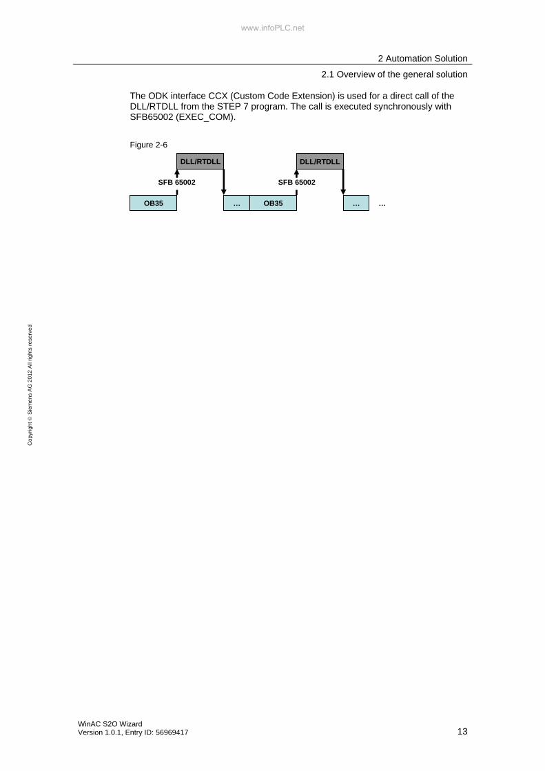
The ODK interface CCX (Custom Code Extension) is used for a direct call of the DLL/RTDLL from the STEP 7 program. The call is executed synchronously with SFB65002 (EXEC_COM).
Figure 2-6
OB35
DLL/RTDLL
… OB35
DLL/RTDLL
… …
SFB 65002 SFB 65002
www.infoPLC.net

2 Automation Solution
2.2 Hardware and software components used
14 WinAC S2O Wizard
Version 1.0.1, Entry ID: 56969417
Co
pyr
igh
t S
iem
en
s A
G 2
01
2 A
ll rig
hts
re
serv
ed
2.2 Hardware and software components used
The application document was generated using the following components:
2.2.1 Hardware components
Table 2-3
Component Qty. Order number Note
SIMATIC IPC427C (MICROBOX PC)
1 6S7647-7BL30-0QA0
2.2.2 Software components
Table 2-4: Third-party software
Component Qty. Order number Note
MATLAB V7.11 (R2010b) 1 -
Simulink V7.6 1 -
Real-Time Workshop V7.6 1 -
Real-Time Workshop Embedded Coder V5.6
1 -
www.mathworks.com
Microsoft Visual Studio 2008 Professional
1 - www.microsoft.com
IntervalZero SDK V9.1.2 1 - www.intervalzero.com
Table 2-5: SIMATIC software components
Component Qty. Order number Note
STEP 7 V5.5 1 6ES7810-4C.10-..
S7-SCL V5.3 1 6ES7811-1CC05-..
STEP 7 Prof. V11 SP2 1 6ES7822-1A.01-..
Table 2-6: WinAC software components
Component Qty. Order number Note
WinAC RTX 2010 1 6ES7671-0RC08-0YA0
WinAC ODK V4.2 1 6ES7806-1CC03-0BA0
www.infoPLC.net

2 Automation Solution
2.2 Hardware and software components used
WinAC S2O Wizard Version 1.0.1, Entry ID: 56969417 15
Co
pyr
igh
t S
iem
en
s A
G 2
01
2 A
ll rig
hts
re
serv
ed
2.2.3 Sample files and projects
The following list includes all files and projects used in this example.
Table 2-7
Component Note
Setup: WinAC S2O Wizard
Setup for installation of the WinAC S2O Wizard
Compressed (zipped) Folder: S2O_Examples
This zipped archive contains the following data:
• 01_Simulink_Model
Simulink Model “PID_Simple_Model.mdl”
• 02_Simulink_C_Code
C-Code of the Simulink subsystem "PID_simple_disc" created with Real-Time Workshop Embedded Coder
• 03_S2O_Code
Files created with WinAC S2O Wizard for – STEP 7 V5.x with DLL – STEP 7 V5.x with RTDLL
– STEP 7 V11 with DLL – STEP 7 V11 with RTDLL
• 04_STEP7_V5x_Project Example project for STEP 7 V5.x
• 05_STEP7_V11_Project
Example project for STEP 7 V11
www.infoPLC.net

3 Basics
16 WinAC S2O Wizard
Version 1.0.1, Entry ID: 56969417
Co
pyr
igh
t S
iem
en
s A
G 2
01
2 A
ll rig
hts
re
serv
ed
3 Basics All basic topics on the used software components of this application are available on the Internet via the following links.
Mathworks • MATLAB
Program used for solving mathematical tasks and for the graphic display of the results. Programming in MATLAB is done in a proprietary language and offers a great scope of mathematical functions.
• Simulink MATLAB add-on for the graphical programming of models and simulations. Simulink offers an extensive library with functions for the creation, for instance, of control applications.
• Real-Time Workshop Embedded Coder Simulink add-on for the compilation of subsystems in C/C++ code.
www.mathworks.com
Microsoft Visual Studio 2008 Visual Studio is a development environment with integrated high-level languages such as C, C++, C#, Basic.
www.microsoft.com
IntervalZero IntervalZero provides a real-time environment for PC systems: IntervalZero RTX. To create RTDLL files with Microsoft Visual Studio, the matching IntervalZero RTX SDK (Software Development Kit) is required.
www.intervalzero.com
STEP 7 STEP 7 is the development environment for the programming and commissioning of SIMATIC PLCs.
http://www.automation.siemens.com/mcms/simatic-controller-software/en/Pages/Default.aspx
www.infoPLC.net

3 Basics
WinAC S2O Wizard Version 1.0.1, Entry ID: 56969417 17
Co
pyr
igh
t S
iem
en
s A
G 2
01
2 A
ll rig
hts
re
serv
ed
SIMATIC WinAC RTX and WinAC ODK • WinAC RTX
SIMATIC WinAC RTX is the SIMATIC Software Controller for PC-based automation solutions and it permits realtime-capable deterministic control on the PC.
• WinAC ODK The WinAC option Open Development Kit (ODK) permits via three different interfaces the flexible use of all resources of the PC from the control program to expand the high-performance PLC functionality. The programmer can use all Windows OS functions and system resources – and thus also the access to external hardware and software components.
http://www.automation.siemens.com/mcms/programmable-logic-controller/en/software-plc/Pages/Default.aspx
www.infoPLC.net

4 Functional Mechanisms of this Application
4.1 General overview
18 WinAC S2O Wizard
Version 1.0.1, Entry ID: 56969417
Co
pyr
igh
t S
iem
en
s A
G 2
01
2 A
ll rig
hts
re
serv
ed
4 Functional Mechanisms of this Application
4.1 General overview
The following picture shows the complete function mechanism of the application from the creation of the PID controller in MATLAB/Simulink to the runtime on the target system.
Figure 4-1
Industry PC
SIMATIC WinAC RTX
WinAC ODK Program
PID ControllerDLL/RTDLL File
STEP 7 Program
OB 35
simulated processFB PROC_C
PID ControllerFB (SCL Source)
DLL / RTDLLCall
• MATLAB• Simulink• RTWEC
C/C++ Code
WinAC S2O Wizard
www.infoPLC.net

4 Functional Mechanisms of this Application
4.2 Data types
WinAC S2O Wizard Version 1.0.1, Entry ID: 56969417 19
Co
pyr
igh
t S
iem
en
s A
G 2
01
2 A
ll rig
hts
re
serv
ed
4.2 Data types
Since STEP 7, WinAC ODK and the Real-Time Workshop Embedded Coder use different data types, type conversion must be executed at the program interfaces. The WinAC S2O Wizard recognizes the data types of the RTWEC C/C++ program and adapt the data in the WinAC ODK program and STEP 7 program (SCL source). Type conversion is performed when the WinAC S2O Wizard is executed. The following table shows the respective data types.
Table 4-1
C/C++ (RTWEC)
C/C++ (WinAC ODK)
Bytes STEP 7
int8_T, unint8_T, boolean_T, char_T, uchar_T, byte_T
char 1 CHAR
int16_T, uint16_T short int 2 INT int32_T, uint32_T, int_T, uint_T int 4 DINT ulong_T long int 4 DINT real32_T float 4 REAL real_T, time_T, real_64_T double 8 REAL (4 Byte)
Attention: Data loss - long double 8 REAL (4 Byte)
Attention: Data loss - Bool 1 BOOL
If bigger data types are used in the WinAC ODK program than in STEP 7, data loss may occur. The following picture shows the interfaces and data types of this application. Here a loss-linked data conversion takes place from type [double] to [float] in the WinAC ODK program. This has no impact on the application example though because the accuracy is still high enough despite the data loss. Figure 4-2
STEP 7 Program
WinAC ODK Program
RTWECC/C++ Code
Setpoint
Process_value
PID_out
Simulink Subsystem
[real_T]
[real_T]
[real_T]
[double]
[double]
[REAL]
[REAL]
[REAL]
data losscaused by
type convertion
[float][double]
www.infoPLC.net

5 Installation
5.1 Hardware installation
20 WinAC S2O Wizard
Version 1.0.1, Entry ID: 56969417
Co
pyr
igh
t S
iem
en
s A
G 2
01
2 A
ll rig
hts
re
serv
ed
5 Installation
5.1 Hardware installation
All PC systems with installed WinAC RTX can be used for this application. A SIMATIC IPC427C (MICROBOX PC) was used in this example.
Figure 5-1
The S7 program is loaded with the following configuration:
• PG/PC interface: Ethernet (192.168.2.200)
• IPC427C interface: PROFINET CP1616 (192.168.2.10)
For further information about the IPC427C refer to the following manual: http://support.automation.siemens.com/WW/view/en/37028954
www.infoPLC.net

5 Installation
5.2 Software installation
WinAC S2O Wizard Version 1.0.1, Entry ID: 56969417 21
Co
pyr
igh
t S
iem
en
s A
G 2
01
2 A
ll rig
hts
re
serv
ed
5.2 Software installation
Table 5-1
No. Action Comment
1 Install MATLAB V7.11 (R2010b) Simulink V7.6 Real-Time Workshop V7.6 Real-Time Workshop Embedded Coder V5.6
2 Install Microsoft Visual Studio 2008 Professional
3 Install optionally IntervalZero SDK V9.1.2
for RTDLL creation
4 Install STEP V5.5 and S7-SCL V5.3 Install alternatively STEP 7 V11 Professional with Service Pack 2
Manual: http://support.automation.siemens.com/WW/view/en/10805384/133300
5 Install WinAC ODK V4.2
Manual: http://support.automation.siemens.com/WW/view/en/12840073/133300
6 Install WinAC RTX 2010 on a PC system (SIMATIC IPC427C)
Manual: http://support.automation.siemens.com/WW/view/en/10805641/133300
www.infoPLC.net

5 Installation
5.3 Installing the application software
22 WinAC S2O Wizard
Version 1.0.1, Entry ID: 56969417
Co
pyr
igh
t S
iem
en
s A
G 2
01
2 A
ll rig
hts
re
serv
ed
5.3 Installing the application software
Table 5-2
No. Action Comment
1 Install WinAC S2O Wizard
Prerequisite: Windows XP Professional Microsoft Visual Studio 2008 Professional STEP V5.5 and S7-SCL V5.3 or STEP 7 V11 Professional with Service Pack 2 WinAC ODK V4.2
5.4 Installing the Example Files
Table 5-3
No. Action Comment
1 Unzip the file "S2O_Examples.zip"
www.infoPLC.net

6 MATLAB / Simulink /Real-Time Workshop Embedded Coder
6.1 Controller creation and process simulation with MATLAB/Simulink
WinAC S2O Wizard Version 1.0.1, Entry ID: 56969417 23
Co
pyr
igh
t S
iem
en
s A
G 2
01
2 A
ll rig
hts
re
serv
ed
6 MATLAB / Simulink /Real-Time Workshop Embedded Coder
6.1 Controller creation and process simulation with MATLAB/Simulink
6.1.1 The process
In this application a process is simulated which behaves similarly to a temperature application. The reaction of the process to a step from 0 to 50 °C is very slow and it approaches aperiodically to the value 50 (Figure 6-1). The Y axis represents the temperature in degrees Celsius [°C] and the X axis represents the time in seconds [s].
Figure 6-1: Step response of the process
As a mathematical model there is a continuous PT3 controlled system with the following formula:
151
1101
1101)(
+⋅
+⋅
+=
ssssG
or
Table 6-1: Controlled system parameter of the continuous process
Controlled system parameter Remark
GAIN = 1 Amplification TM_LAG = 10s TM_LAG = 10s TM_LAG = 5s
Delay times
www.infoPLC.net

6 MATLAB / Simulink /Real-Time Workshop Embedded Coder
6.1 Controller creation and process simulation with MATLAB/Simulink
24 WinAC S2O Wizard
Version 1.0.1, Entry ID: 56969417
Co
pyr
igh
t S
iem
en
s A
G 2
01
2 A
ll rig
hts
re
serv
ed
The process is simulated in MATLAB/Simulink in the form of three PT1 functions which are switched in series. Figure 6-2: Simulink model: Step response of the continuous process
This model is a continuous process. The process and the PID controller will be called in the PLC (WinAC RTX here) in a cyclic organization block with the cycle T = 100ms later. That means it is a discrete process simulation and a discrete PID controller. Therefore, the continuous controlled system must be converted into a discrete controlled system. The TUSTIN transformation is used in this case:
−+−−−=⋅= ...
2)1()1(1)ln(1 2z
zT
zT
s )1(1 −⋅≈ zT
s
1.0100 == msT
From the continuous process...
151
1101
1101)(
+⋅
+⋅
+=
ssssG
after the TUSTIN transformation...
1)1(1.0
15
1
1)1(1.0
110
1
1)1(1.0
110
1)(+−⋅⋅
⋅+−⋅⋅
⋅+−⋅⋅
=zzz
zG
the discrete process is obtained:
49501
991001
991001)(
−⋅
−⋅
−=
zzzzG
The model in MATLAB/Simulink looks like this then: Figure 6-3: Simulink model: Step response of the discrete process
www.infoPLC.net

6 MATLAB / Simulink /Real-Time Workshop Embedded Coder
6.1 Controller creation and process simulation with MATLAB/Simulink
WinAC S2O Wizard Version 1.0.1, Entry ID: 56969417 25
Co
pyr
igh
t S
iem
en
s A
G 2
01
2 A
ll rig
hts
re
serv
ed
6.1.2 The PID controller
The following section demonstrates how a subsystem is created in Simulink. In this case, this is a simple PID controller. The description merely refers to the setup of the simulation of the discrete control loop. For further information about the PID control refer to the manual "Controlling with SIMATIC".
Note Alternatively, you can also open the file "PID_Simple_Model.mdl" in the directory "01_Simulink_Model" with MATLAB/Simulink. The model contains all of the following steps of this section and additional simulations:
1. Step response of the continuous process
2. Simulation of the continuous control loop
3. Step response of the discrete process
4. Simulation of the discrete control loop
www.infoPLC.net

6 MATLAB / Simulink /Real-Time Workshop Embedded Coder
6.1 Controller creation and process simulation with MATLAB/Simulink
26 WinAC S2O Wizard
Version 1.0.1, Entry ID: 56969417
Co
pyr
igh
t S
iem
en
s A
G 2
01
2 A
ll rig
hts
re
serv
ed
Creating subsystem with PID controller in MATLAB/Simulink
Table 6-2
Steps Instructions
1. Open MATLAB.
2. Create a new model and save it under the name "PID_Simple_Model".
3. Open the "Simulink Library Browser".
4. Add to the model a "Subsystem" by Drag&Drop from the "Simulink Library".
www.infoPLC.net

6 MATLAB / Simulink /Real-Time Workshop Embedded Coder
6.1 Controller creation and process simulation with MATLAB/Simulink
WinAC S2O Wizard Version 1.0.1, Entry ID: 56969417 27
Co
pyr
igh
t S
iem
en
s A
G 2
01
2 A
ll rig
hts
re
serv
ed
Steps Instructions
5. Open the subsystem with a double-click on the block.
6. Add the following blocks to the subsystem by Drag&Drop from the Simulink Library:
• Further input: "Simulink – Sources – In1" • Adding block: "Simulink – Math Operations – Sum" • PID controller: "Simulink – Discrete – Discrete PID Controller"
7. Open the block parameters of "Sum" with a double-click and change the value of the parameter "List of signs" to " |+- ".
8. Then close the parameterization mask.
9. Open the block parameters of "Discrete PID controller" with a double-click and apply the following values.
Note: • Sample time is set to 0.1 for 100 ms. The controller and the process will
be called in WinAC RTX in OB35 (cycle 100 ms) later. • The PID values were determined empirically for this application. A good
control response is achieved with little overshoot with this parameterization.
www.infoPLC.net

6 MATLAB / Simulink /Real-Time Workshop Embedded Coder
6.1 Controller creation and process simulation with MATLAB/Simulink
28 WinAC S2O Wizard
Version 1.0.1, Entry ID: 56969417
Co
pyr
igh
t S
iem
en
s A
G 2
01
2 A
ll rig
hts
re
serv
ed
Steps Instructions
10. Under the tab "PID Advanced" set a limitation from 0 to 100 for the PID output.
11. Close the parameterization mask.
12. Wire the blocks and assign the following names.
13. Close the subsystem.
www.infoPLC.net

6 MATLAB / Simulink /Real-Time Workshop Embedded Coder
6.1 Controller creation and process simulation with MATLAB/Simulink
WinAC S2O Wizard Version 1.0.1, Entry ID: 56969417 29
Co
pyr
igh
t S
iem
en
s A
G 2
01
2 A
ll rig
hts
re
serv
ed
6.1.3 Simulation of the complete control loop
The response of the complete control loop can be checked directly in Simulink due to the simulation of the process and the created PID controller. To do this, proceed as follows. Table 6-3
Steps Instructions
1. Insert the three blocks of the type "Discrete Transfer Fcn" by Drag&Drop from the Simulink Library into the Simulink model:
• "Simulink – Discrete – „Discrete Transfer Fcn"
2. Open the "Discrete Transfer Fcn" blocks one after the other and parameterize them as follows. Block 1 and 2:
Block 3:
Close the parameterization masks.
www.infoPLC.net

6 MATLAB / Simulink /Real-Time Workshop Embedded Coder
6.1 Controller creation and process simulation with MATLAB/Simulink
30 WinAC S2O Wizard
Version 1.0.1, Entry ID: 56969417
Co
pyr
igh
t S
iem
en
s A
G 2
01
2 A
ll rig
hts
re
serv
ed
Steps Instructions
3. Insert the following blocks: • "Simulink – Sources – Constant"
for the Setpoint • "Simulink – Sinks – Scope"
for visualizing the control loop • "Simulink – Signal Routing – Mux"
for merging the signals
4. With a double-click open the block "Mux" and change the value of the parameter "number of inputs" to "3". Close the parameterization mask.
5. With a double-click open the block "Constant" and change the value "Constant Value" to 50 and "Sample time" to 0.1 for 100 ms. Close the parameterization mask.
6. Wire the complete control loop and assign the following names.
www.infoPLC.net

6 MATLAB / Simulink /Real-Time Workshop Embedded Coder
6.1 Controller creation and process simulation with MATLAB/Simulink
WinAC S2O Wizard Version 1.0.1, Entry ID: 56969417 31
Co
pyr
igh
t S
iem
en
s A
G 2
01
2 A
ll rig
hts
re
serv
ed
Steps Instructions
7. • Open the "Scope" block with a double-click. • Select 150 for the "Simulation stop time" and start the simulation with
the "Start simulation" icon in the menu bar of the Simulink model. • Click on the "Autoscale" icon in the menu bar of the "Scope" block. You see the simulation of the complete control loop as a result.
3
1
2
1. Setpoint 2. Process_value 3. PID_out
www.infoPLC.net

6 MATLAB / Simulink /Real-Time Workshop Embedded Coder
6.2 C/C++ Generation with RTWEC
32 WinAC S2O Wizard
Version 1.0.1, Entry ID: 56969417
Co
pyr
igh
t S
iem
en
s A
G 2
01
2 A
ll rig
hts
re
serv
ed
6.2 C/C++ Generation with RTWEC
RTWEC is an add-on of Mathworks which generates C/C++ code from Simulink subsystems. For detailed information about the Real-Time Workshop Embedded Coder refer to www.mathworks.com.
Figure 6-4
Real-Time Workshop Embedded Coder
RTWEC default settings The following settings are made for RTWEC in this application. Table 6-4
Steps Instructions
1. Open a Simulink model.
2. In the menu click on "Tools – Real-Time Workshop – Options…"
3. A window is displayed with a navigation bar. The entry "Real-Time Workshop" is selected by default. Enter the following parameters: Navigation item "Real-Time Workshop"
– System target file: ert.tlc – Language: C++ – Click the button "Set objectives"
Shift "Traceability" and "Execution efficiency" with the "->" button to the right field
Navigation item "Code Placement"
– File packaging format: Compact
www.infoPLC.net

6 MATLAB / Simulink /Real-Time Workshop Embedded Coder
6.2 C/C++ Generation with RTWEC
WinAC S2O Wizard Version 1.0.1, Entry ID: 56969417 33
Co
pyr
igh
t S
iem
en
s A
G 2
01
2 A
ll rig
hts
re
serv
ed
Generate C/C++ Code
In Table 6-5 you can see how a subsystem is compiled into C++ in a Simulink model. In this case the block "PID_simple_disc" is compiled from the MATLAB/Simulink model (PID_Simple.mdl) into C/C++.
Table 6-5
Steps Instructions
1. With the right mouse-button click on the subsystem "PID_simple_disc"
2. Select "Real-Time Workshop – Build Subsystem…" in the context menu
3. In the window "Build code for Subsystem" click on the "Build" button
After the C/C++ code has been created, the window "Build Code for Subsystem" is closed automatically. The generated code is located in the directory of the Simulink model "...\PID_simple_disc_rtw".
Figure 6-5
www.infoPLC.net

7 WinAC Simulink to ODK (S2O) Wizard
34 WinAC S2O Wizard
Version 1.0.1, Entry ID: 56969417
Co
pyr
igh
t S
iem
en
s A
G 2
01
2 A
ll rig
hts
re
serv
ed
7 WinAC Simulink to ODK (S2O) Wizard WinAC S2O Wizard automatically generates all required blocks and files for the integration of the Simulink subsystem into a STEP 7 project. An SCL source and a DLL or RTDLL file will be created out of the generated C/C++ code of the RTWEC. With STEP 7 V5.x programs, integration is possible due to the WinAC S2O Wizard in addition. Finally, you have to simply load the STEP 7 program and the DLL or RTLL to a PC system with WinAC RTX.
Note Microsoft Visual Studio 2008 is required for creation of the DLL or RTDLL.
Creation of an RTDLL also requires the Software Development Kit (SDK) IntervalZero. http://www.intervalzero.com/
Table 7-1
Steps Instructions
1. Open the "WinAC S2O Wizard".
2. Mask "Select Source project"
• "Select the C/C++ source:" Navigate to the path where the Real-Time Workshop Embedded Coder stored the resulting C/C++ sources of the block "PID_simple_disc". Select the file "PID_simple_disc.cpp" (same name as the created block in MATLAB/Simulink).
• "Select the ODK project – destination folder:" By default a folder (here "PID_simple_disc_S2O") is created as the destination path for the ODK project in the folder of the selected source file.
• "Generate SCL Block:" Define whether the ODK project shall be created for STEP 7 V5.x or for STEP 7 V11.
• "ODK project type:" Define whether a Windows DLL or Real-Time DLL shall be created in the ODK project.
• Click the "Next >" button.
www.infoPLC.net

7 WinAC Simulink to ODK (S2O) Wizard
WinAC S2O Wizard Version 1.0.1, Entry ID: 56969417 35
Co
pyr
igh
t S
iem
en
s A
G 2
01
2 A
ll rig
hts
re
serv
ed
Steps Instructions
3. If you select "STEP 7 V5.x" (for STEP 7 V11 you proceed directly to step 4): Mask "Select destination project"
• "STEP 7 project:" Select the STEP 7 project (here "S2O_PID_simple") into which the ODK project shall be integrated. If the desired project is not included in the list, you have to open it first with the SIMATIC Manager. By opening the project it is entered in the list.
• "S7-Program:" Select the program or block folder in the project into which the ODK project is to be integrated ("PID_simple_disc").
• "Name for new SCL Source:"
Specify the name for the SCL source to be created. The name of the C/C++ source file is set by default (here "PID_simple_disc").
• "Number for new Function Block:" A function block will be created automatically from the SCL source later. Select the name of the function block. The number of the next free function block in the program is specified by default.
• "Symbolic name for Function Block:" Select optionally the symbolic name of the function block. The name of the C/C++ source file is set by default (here "PID_simple_disc").
• "Generate SCL source only:" (optional) Integration into the STEP 7 project can be deactivated and you may create only the SCL source. Therefore, you have to specify only the name for the SCL source to be created.
• Click the "Finish" button. Then the WinAC S2O Wizard creates the SCL source, the function block and the DLL or RTDLL file. The following folders will be stored in the destination folder "PID_simple_disc_S2O" after the generation:
– _S2O_Source All source files are located here which were created during the generation.
– Binary The DLL or RTDLL file is located here.
– SCL Source The SCL source is located here.
www.infoPLC.net
7 WinAC Simulink to ODK (S2O) Wizard
36 WinAC S2O Wizard
Version 1.0.1, Entry ID: 56969417
Co
pyr
igh
t S
iem
en
s A
G 2
01
2 A
ll rig
hts
re
serv
ed
Steps Instructions
4. This step is only required for "STEP 7 V11": Mask "Select destination project"
• "Name for new SCL source:" Specify the name for the SCL source to be created. The name of the C/C++ source file is set by default (here "PID_simple_disc").
• "Symbolic name for Function Block:" Select optionally the symbolic name of the function block. The name of the C/C++ source file is set by default (here "PID_simple_disc").
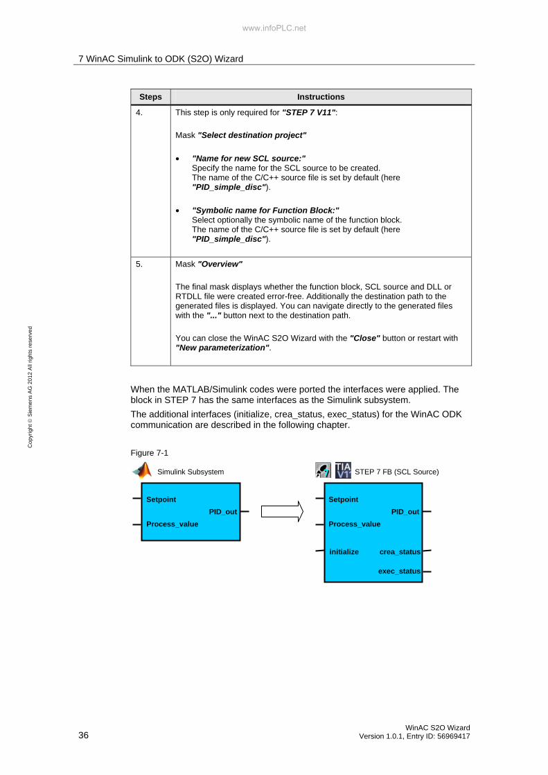
5. Mask "Overview" The final mask displays whether the function block, SCL source and DLL or RTDLL file were created error-free. Additionally the destination path to the generated files is displayed. You can navigate directly to the generated files with the "..." button next to the destination path. You can close the WinAC S2O Wizard with the "Close" button or restart with "New parameterization".
When the MATLAB/Simulink codes were ported the interfaces were applied. The block in STEP 7 has the same interfaces as the Simulink subsystem. The additional interfaces (initialize, crea_status, exec_status) for the WinAC ODK communication are described in the following chapter.
Figure 7-1
Setpoint
Process_value
PID_out
Setpoint
Process_value
PID_out
initialize crea_status
exec_status
Simulink Subsystem STEP 7 FB (SCL Source)
www.infoPLC.net

8 Program and Commissioning with STEP 7
8.1 Configuration with STEP 7 V5.5
WinAC S2O Wizard Version 1.0.1, Entry ID: 56969417 37
Co
pyr
igh
t S
iem
en
s A
G 2
01
2 A
ll rig
hts
re
serv
ed
8 Program and Commissioning with STEP 7 This chapter describes the configuration both with STEP 7 V5.5 and with STEP 7 V11. You can choose the variant which suits your requirements best.
8.1 Configuration with STEP 7 V5.5
8.1.1 Programming
Note You have to install the software WinAC ODK in order to integrate subsystems. In addition, the WinAC ODK Library must be integrated in the SIMATIC Manager since the blocks SFB65001 (CREA_COM) and SFB65002 (EXEC_COM) are needed for the execution of the DLL/RTDLL.
For further information on WinAC ODK refer to http://www.automation.siemens.com/mcms/programmable-logic-controller/en/software-plc/simatic-winac-odk/Pages/Default.aspx
www.infoPLC.net

8 Program and Commissioning with STEP 7
8.1 Configuration with STEP 7 V5.5
38 WinAC S2O Wizard
Version 1.0.1, Entry ID: 56969417
Co
pyr
igh
t S
iem
en
s A
G 2
01
2 A
ll rig
hts
re
serv
ed
The folder "…\04_STEP7_V5x_Project" contains the example project for STEP7 V5.5 with the following contents:
• WinAC RTX This is only the hardware configuration of a PC station with a WinAC RTX. The program is empty. This configuration just serves as a template.
• PID Simple This example provides a prepared program for integration through the WinAC S2O Wizard. The following blocks have been created already:
– OB35 (CYC_INT5) as cyclic OB with 100 ms cycle. The simulated controlled system and the PID controller (PID_simple_disc) are called in this block.
– DB35 (Data) as a global data block. It contains all required variables: - Setpoint [Real], - PID_output [Real], - Process_value [Real], - crea_status [Word] (provides the status via CREA_COM), - exec_status[Word] (provides the status via EXEC_COM) - initialize [Bool]
– FB100 (PROC_C) with Instanz-DB100 Simulated PT3 process (parameterized like the process in MATLAB/Simulink)
– SFB65001 (CREA_COM) for initialization of the DLL/RTDLL file
– SFB65002 (EXEXC_COM) for execution of the DLL/RTDLL file
– VAT_1 Variable table with the variables of DB35 (DATA)
• PID_Simple_dll_final This program contains a complete programming with integration of the PID controller from MATLAB/Simulink through the WinAC S2O Wizard. A DLL call is used in this program.
• PID_Simple_rtdll_final This program contains a complete programming with integration of the PID controller from MATLAB/Simulink through the WinAC S2O Wizard. An RTDLL call is used in this program.
www.infoPLC.net

8 Program and Commissioning with STEP 7
8.1 Configuration with STEP 7 V5.5
WinAC S2O Wizard Version 1.0.1, Entry ID: 56969417 39
Co
pyr
igh
t S
iem
en
s A
G 2
01
2 A
ll rig
hts
re
serv
ed
The following steps complete the program "PID_simple" with the "PID_simple_disc" block from the WinAC S2O Wizard:
Table 8-1
Steps Instructions
1. Open the SIMATIC Manager.
2. Open the example project "S2O_PID_simple" in the directory "...\04_STEP7_V5x_Project"
3. When you have executed the WinAC SO2 Wizard as described in the previous section, the SCL source "PID_simple_disc" has already been integrated and the function block ("PID_simple_disc") has already been created.
4. Open OB 35 and insert the "FB PID_simple_disc" into the "Network 2: PID Controller“. Interconnect the inputs and outputs as shown in the picture.
5. Load the program to the WinAC RTX.
6. Copy the DLL (C_ODK.dll) or RTDLL (C_ODK.rtdll) into the directory C:\ of the PC system with the WinAC RTX. RTDLL files have to be registered still (see the following instructions).
7. Set the WinAC into the RUN mode.
www.infoPLC.net

8 Program and Commissioning with STEP 7
8.1 Configuration with STEP 7 V5.5
40 WinAC S2O Wizard
Version 1.0.1, Entry ID: 56969417
Co
pyr
igh
t S
iem
en
s A
G 2
01
2 A
ll rig
hts
re
serv
ed
Note If you wish to use a different path for storing the DLL/RTLL file, you have to adapt the path accordingly in the SCL source.
Variable: "DLL_name"
Alternatively, you can change the variable also directly in the generated function block
"Interface – Static – DLL_name"
Note If an RTDLL shall be called in WinAC RTX, it has to be registered in the IntervalZero Runtime after you copied it to the PC system.
Select in the PC system "Start - Programs - IntervalZero - RTX 2009 - Tools - RtssRun". Register the RTDLL file like shown in the picture.
www.infoPLC.net

8 Program and Commissioning with STEP 7
8.1 Configuration with STEP 7 V5.5
WinAC S2O Wizard Version 1.0.1, Entry ID: 56969417 41
Co
pyr
igh
t S
iem
en
s A
G 2
01
2 A
ll rig
hts
re
serv
ed
8.1.2 Commissioning
After having loaded the program to the WinAC RTX, execute the following steps for commissioning. Table 8-2
Steps Instructions
1. Open the "VAT_1" variable table
2. Click the icon "Monitor Variable"
3. Change the value of the variable "initialize" to "TRUE" and click the icon "Modify Variable".
4. Change the value of the variable "initialize" to "FALSE" and click the icon "Modify Variable".
5. Change the value of the variable "Setpoint" to a desired value, e.g. 50, and click the icon "Modify Variable". Due to the change of the setpoint, the PID controller will output an output value. The process will change accordingly until it corresponds to the "Setpoint".
Figure 8-1
Note The following variables can be used to detect errors.
Variable "crea_status" corresponds to SFB65001.Status Variable "exec_status" corresponds to SFB65002.Status
For the error code refer to the manual WinAC ODK. http://support.automation.siemens.com/WW/view/en/35948966
www.infoPLC.net

8 Program and Commissioning with STEP 7
8.2 Configuration with STEP 7 V11
42 WinAC S2O Wizard
Version 1.0.1, Entry ID: 56969417
Co
pyr
igh
t S
iem
en
s A
G 2
01
2 A
ll rig
hts
re
serv
ed
8.2 Configuration with STEP 7 V11
8.2.1 Programming
The folder "…\05_STEP7_V11_Project" contains the example project for STEP7 V11 with the following contents:
• PID_Simple This example provides a prepared program for integration through the WinAC S2O Wizard. The following blocks have been created already: – OB35 (CYC_INT5) as cyclic OB with 100 ms cycle. The simulated
controlled system and the PID controller (PID_simple_disc) are called in this block after the integration.
– DB35 (Data) as a global data block. It contains all required variables: - Setpoint [Real], - PID_output [Real], - Process_value [Real], - crea_status [Word] (provides the status via CREA_COM), - exec_status[Word] (provides the status via EXEC_COM) - initialize [Bool]
– FB100 (PROC_C) with Instanz-DB100 Simulated PT3 process (parameterized like the process in MATLAB/Simulink)
– Watch table_1 Variable table with the variables of DB35 (DATA)
• PID_Simple_dll_final This program contains a complete programming with integration of the PID controller from MATLAB/Simulink through the WinAC S2O Wizard. A DLL call is used in this program.
• PID_Simple_rtdll_final This program contains a complete programming with integration of the PID controller from MATLAB/Simulink through the WinAC S2O Wizard. A RTDLL call is used in this program.
The following steps complete the program "PID_simple" with the "PID_simple_disc" block from the S2O Wizard:
Table 8-3
Steps Instructions
1. Open the TIA Portal V11
2. Open the example project "S2O_PID_simple" in the directory "...\05_STEP7_V11_Project"
3. Change over to the "Project View" (bottom left)
www.infoPLC.net
8 Program and Commissioning with STEP 7
8.2 Configuration with STEP 7 V11
WinAC S2O Wizard Version 1.0.1, Entry ID: 56969417 43
Co
pyr
igh
t S
iem
en
s A
G 2
01
2 A
ll rig
hts
re
serv
ed
Steps Instructions
4. Expand the tree under "PID_Simple [IPC427C PN]".
5. Expand the tree under "WinAC RTX [CPU]" further.
6. With a double-click select "Add new external file" under the folder "External source files"
7. Select "SCL Sources (*.scl)"
8. If you have generated the SCL source and the DLL/RTDLL for STEP 7 V11 with the WinAC S2O Wizard already, navigate to the directory where the SCL source is stored. Alternatively, open the SCL source under "…\03_S2O_Code\PID_simple_disc_S2O_V11_dll" for the DLL call or "…\03_S2O_Code\PID_simple_disc_S2O_V11_rtdll" for the RTDLL call
9. The SCL source is located in the STEP 7 V11 project now. With the right mouse-button click on the SCL source "PID_simple_disc_dll.scl" or "PID_simple_disc_rtdll.scl".
10. In the context menu select "Generate Blocks". A function block is generated out of the SCL source and it is stored in the folder "Program Blocks".
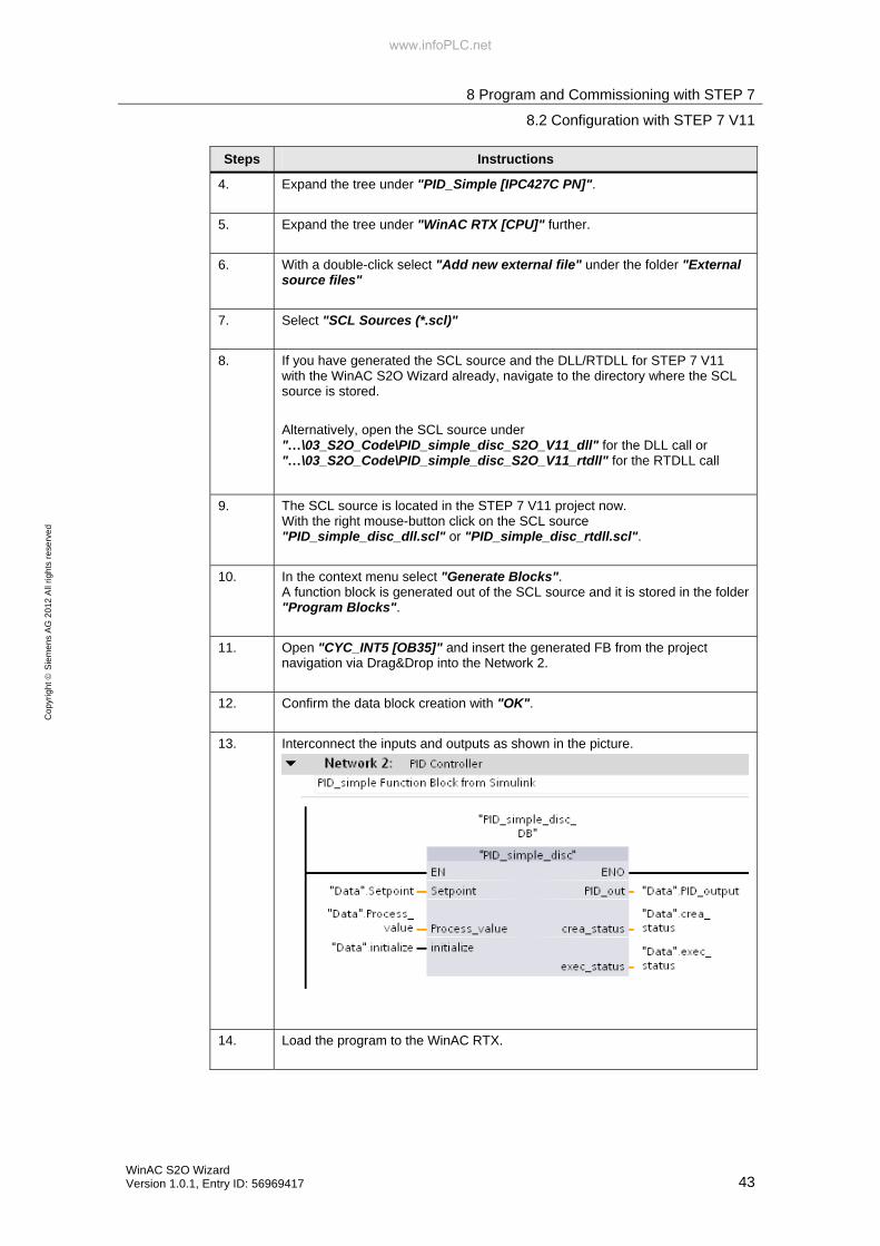
11. Open "CYC_INT5 [OB35]" and insert the generated FB from the project navigation via Drag&Drop into the Network 2.
12. Confirm the data block creation with "OK".
13. Interconnect the inputs and outputs as shown in the picture.
14. Load the program to the WinAC RTX.
www.infoPLC.net

8 Program and Commissioning with STEP 7
8.2 Configuration with STEP 7 V11
44 WinAC S2O Wizard
Version 1.0.1, Entry ID: 56969417
Co
pyr
igh
t S
iem
en
s A
G 2
01
2 A
ll rig
hts
re
serv
ed
Steps Instructions
15. Copy the DLL (C_ODK.dll) or RTDLL (C_ODK.rtdll) into the directory C:\ of the PC system with the WinAC RTX. RTDLL files have to be registered still (see the following instructions).
16. Set the WinAC into the RUN mode.
Note If you wish to use a different path for storing the DLL/RTLL file, you have to adapt the path accordingly in the SCL source and create the function block anew.
Variable: "DLL_name"
Alternatively, you can change the variable also directly in the generated function block
"Interface – Static – DLL_name"
Note If an RTDLL shall be called in WinAC RTX, it has to be registered in the IntervalZero Runtime after you copied it to the PC system.
Select in the PC system "Start - Programs - IntervalZero - RTX 2009 - Tools - RtssRun". Register the RTDLL file like shown in the picture.
www.infoPLC.net

8 Program and Commissioning with STEP 7
8.2 Configuration with STEP 7 V11
WinAC S2O Wizard Version 1.0.1, Entry ID: 56969417 45
Co
pyr
igh
t S
iem
en
s A
G 2
01
2 A
ll rig
hts
re
serv
ed
8.2.2 Commissioning
After having loaded the program to the WinAC RTX and copied the DLL/RTDLL file, execute the following steps for commissioning.
Table 8-4
Steps Instructions
1. Open the variable table "Watch table_1" under "Watch and force table"
2. Click the icon "Monitor all"
3. Change the value of the variable "Init_ODK" to "TRUE" and click the icon "Modify all selected values once and now".
4. Change the value of the variable "Init_ODK" to "FALSE" and click the icon "Modify all selected values once and now".
5. Change the value of the variable "Setpoint" to a desired value, e.g. 50.0, and click the icon "Modify all selected values once and now". Due to the change of the setpoint, the PID controller will output an output value. The process will change accordingly until it corresponds to the set "Setpoint".
Figure 8-2
Note The following variables can be used to detect errors.
Variable "crea_status" corresponds to SFB65001.Status Variable "exec_status" corresponds to SFB65002.Status
For the error code refer to the manual WinAC ODK. http://support.automation.siemens.com/WW/view/en/35948966
www.infoPLC.net

9 References
46 WinAC S2O Wizard
Version 1.0.1, Entry ID: 56969417
Co
pyr
igh
t S
iem
en
s A
G 2
01
2 A
ll rig
hts
re
serv
ed
9 References
9.1 Bibliographic references
This list is by no means complete and only presents a selection of related references. Table 9-1
Topic Title
1 Controlling with SIMATIC "Controlling with SIMATIC" by Jürgen Müller ISBN: 3-89578-255-´6
9.2 Internet Links
The following list is by no means complete and only presents a selection of related sources. Table 9-2
Topic Title
1 Reference to this entry http://support.automation.siemens.com/WW/view/en/56969417
2 Basics for the Solution of Automation Tasks Based on WinAC RTX.
http://support.automation.siemens.com/WW/view/en/21004765
3 Linking Windows Applications to WinAC RTX with WinAC ODK using the Example of SIMATIC Vision Sensors
http://support.automation.siemens.com/WW/view/en/21572937
10 History
Table 10-1
Version Date Revisions
V1.0 12/2011 First edition V1.0.1 02/2012 Addition:
Installation requirement of WinAC S2O Wizard Windows XP Professional
www.infoPLC.net