Embed Size (px)
Citation preview
1
Please note: this is a draft document – it has not been validated. If you choose to use it please check all steps and, if you find something wrong or have suggestions, contact Rob Mueller.
This was presented at the Spring 2016 GMCWS rally at Temecula, CA. Last updated on 5/5/2016
STEERING COLUMN, LOWER STEERING SHAFT, AND STEERING GEAR BOX ALIGNMENT The directional stability of a GMC is affected by a number of factors:
1) Tire pressure and condition 2) Condition of the front and rear suspension components 3) Condition of the steering components 4) Weight distribution fore / aft and driver / passenger sides 5) Vehicle ride height settings front and rear 6) Front and rear wheel alignment 7) Steering column, lower steering shaft, and steering gear box alignment
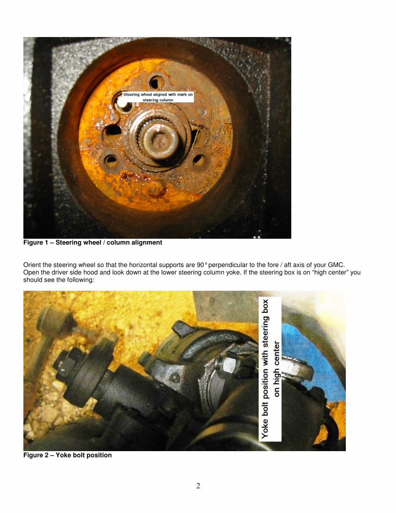
This procedure will address item 7) Steering column, lower steering shaft, and steering gear box alignment. See Addendum B for information on how to address items 1) through 6). The GMC uses a Saginaw re-circulating ball power assisted power steering gear box. For the best directional stability (least wandering) it must be adjusted properly and on “high center” when driving straight ahead. The following procedure and photos will detail how to ascertain that the steering gear box is on “high center” and the steps to take if it is not. I would highly recommend that you download and perform The Basic GMC Motorhome Steering Inspection Guide as found here: http://www.gmceast.com/technical/Mueller_Steering_Inspection_Guide.pdf. Pay particular attention to steps 5 through 8 which check the lower steering shaft and step 9 which checks the steering gear box. Once you have determined that the steering gear box is serviceable and adjusted as per the MM remove the horn and the nut that retains the steering wheel. Verify that the marks on the steering wheel and steering column align as per the photo below. If the marks are not aligned remove the steering wheel and re-install it with the marks aligned. Install the retaining nut finger tight.
2
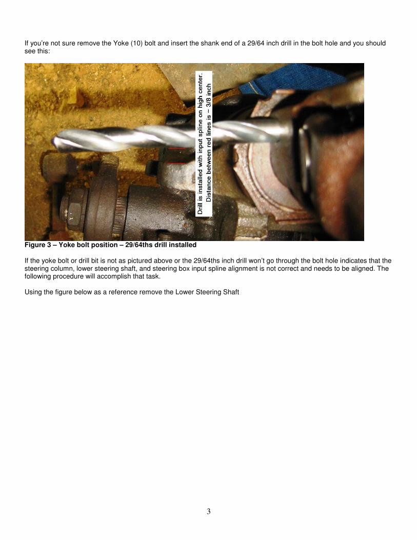
Figure 1 – Steering wheel / column alignment Orient the steering wheel so that the horizontal supports are 90° perpendicular to the fore / aft axis of your GMC. Open the driver side hood and look down at the lower steering column yoke. If the steering box is on “high center” you should see the following:
Figure 2 – Yoke bolt position
3
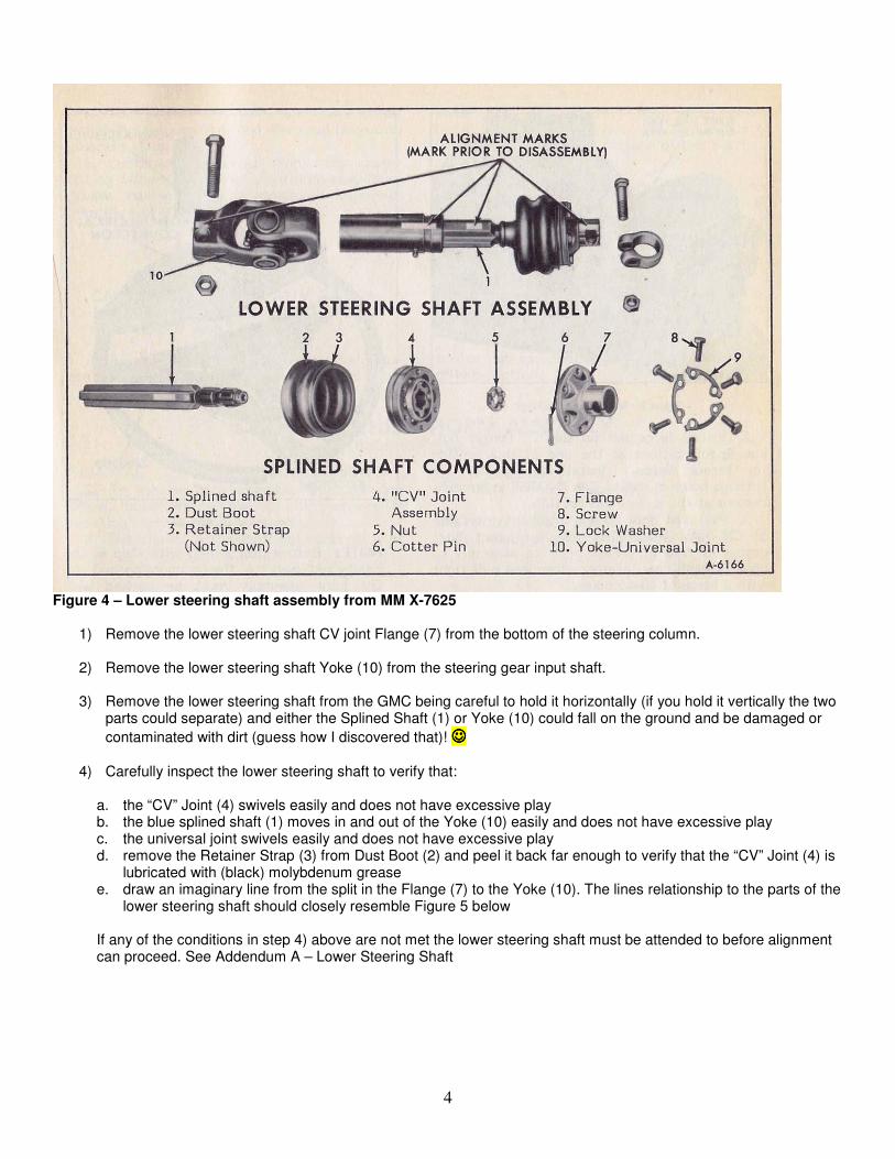
If you’re not sure remove the Yoke (10) bolt and insert the shank end of a 29/64 inch drill in the bolt hole and you should see this:
Figure 3 – Yoke bolt position – 29/64ths drill installed If the yoke bolt or drill bit is not as pictured above or the 29/64ths inch drill won’t go through the bolt hole indicates that the steering column, lower steering shaft, and steering box input spline alignment is not correct and needs to be aligned. The following procedure will accomplish that task. Using the figure below as a reference remove the Lower Steering Shaft
4
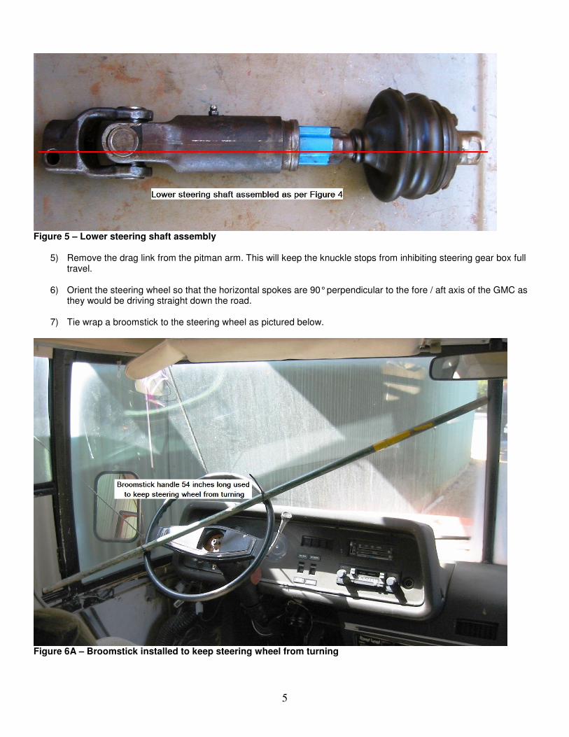
Figure 4 – Lower steering shaft assembly from MM X-7625
1) Remove the lower steering shaft CV joint Flange (7) from the bottom of the steering column.
2) Remove the lower steering shaft Yoke (10) from the steering gear input shaft.
3) Remove the lower steering shaft from the GMC being careful to hold it horizontally (if you hold it vertically the two parts could separate) and either the Splined Shaft (1) or Yoke (10) could fall on the ground and be damaged or
contaminated with dirt (guess how I discovered that)! ☺☺☺☺
4) Carefully inspect the lower steering shaft to verify that:
a. the “CV” Joint (4) swivels easily and does not have excessive play b. the blue splined shaft (1) moves in and out of the Yoke (10) easily and does not have excessive play c. the universal joint swivels easily and does not have excessive play d. remove the Retainer Strap (3) from Dust Boot (2) and peel it back far enough to verify that the “CV” Joint (4) is
lubricated with (black) molybdenum grease e. draw an imaginary line from the split in the Flange (7) to the Yoke (10). The lines relationship to the parts of the
lower steering shaft should closely resemble Figure 5 below
If any of the conditions in step 4) above are not met the lower steering shaft must be attended to before alignment can proceed. See Addendum A – Lower Steering Shaft
5
Figure 5 – Lower steering shaft assembly
5) Remove the drag link from the pitman arm. This will keep the knuckle stops from inhibiting steering gear box full travel.
6) Orient the steering wheel so that the horizontal spokes are 90° perpendicular to the fore / aft axis of the GMC as
they would be driving straight down the road.
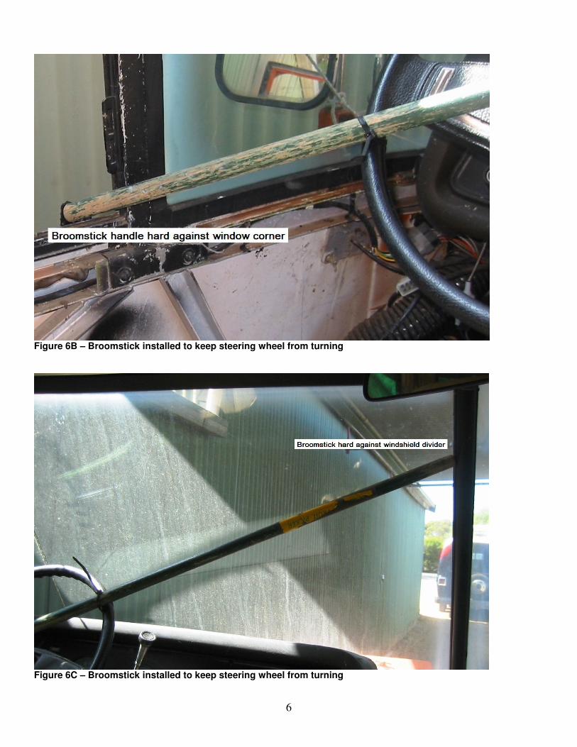
7) Tie wrap a broomstick to the steering wheel as pictured below.
Figure 6A – Broomstick installed to keep steering wheel from turning
6
Figure 6B – Broomstick installed to keep steering wheel from turning
Figure 6C – Broomstick installed to keep steering wheel from turning
7
8) Using a 3/4 inch 12 point socket, turn the steering gear box input shaft from lock to lock counting the number of turns (usually about 3 1/3 turns).
9) Turn the steering gear box input shaft until it stops then turn it back one half the number of turns. This is
approximately the center.
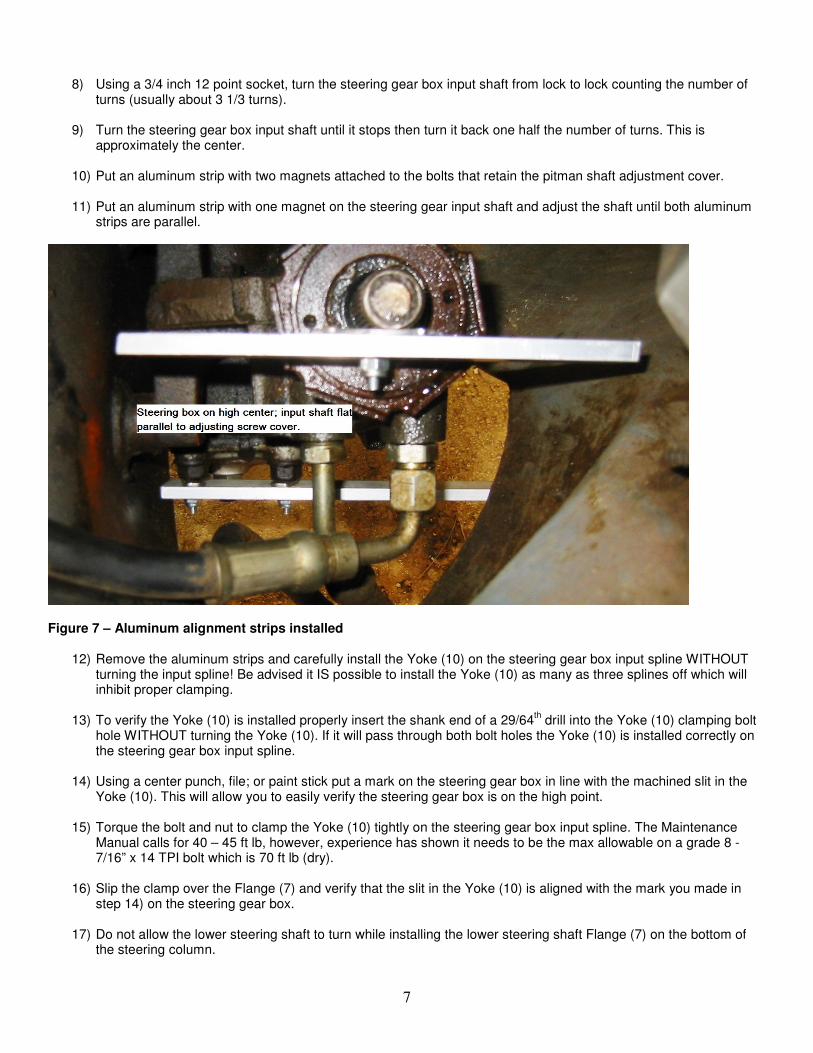
10) Put an aluminum strip with two magnets attached to the bolts that retain the pitman shaft adjustment cover.
11) Put an aluminum strip with one magnet on the steering gear input shaft and adjust the shaft until both aluminum strips are parallel.
Figure 7 – Aluminum alignment strips installed
12) Remove the aluminum strips and carefully install the Yoke (10) on the steering gear box input spline WITHOUT turning the input spline! Be advised it IS possible to install the Yoke (10) as many as three splines off which will inhibit proper clamping.
13) To verify the Yoke (10) is installed properly insert the shank end of a 29/64
th drill into the Yoke (10) clamping bolt
hole WITHOUT turning the Yoke (10). If it will pass through both bolt holes the Yoke (10) is installed correctly on the steering gear box input spline.
14) Using a center punch, file; or paint stick put a mark on the steering gear box in line with the machined slit in the
Yoke (10). This will allow you to easily verify the steering gear box is on the high point.
15) Torque the bolt and nut to clamp the Yoke (10) tightly on the steering gear box input spline. The Maintenance Manual calls for 40 – 45 ft lb, however, experience has shown it needs to be the max allowable on a grade 8 - 7/16” x 14 TPI bolt which is 70 ft lb (dry).
16) Slip the clamp over the Flange (7) and verify that the slit in the Yoke (10) is aligned with the mark you made in
step 14) on the steering gear box.
17) Do not allow the lower steering shaft to turn while installing the lower steering shaft Flange (7) on the bottom of the steering column.
8
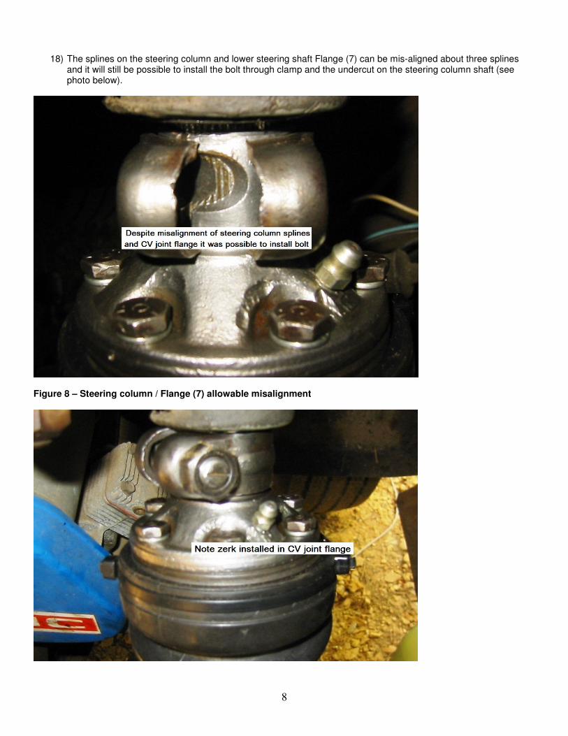
18) The splines on the steering column and lower steering shaft Flange (7) can be mis-aligned about three splines and it will still be possible to install the bolt through clamp and the undercut on the steering column shaft (see photo below).
Figure 8 – Steering column / Flange (7) allowable misalignment
9
Figure 9 – Flange (7) clamp bolt installed and torqued 19) Torque the clamp retaining bolt to 40 – 45 ft lb.
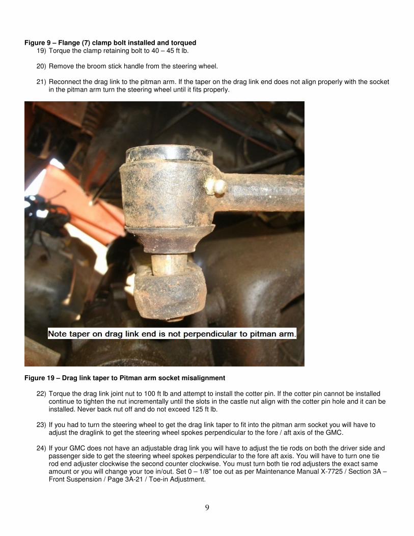
20) Remove the broom stick handle from the steering wheel. 21) Reconnect the drag link to the pitman arm. If the taper on the drag link end does not align properly with the socket
in the pitman arm turn the steering wheel until it fits properly.
Figure 19 – Drag link taper to Pitman arm socket misalignment
22) Torque the drag link joint nut to 100 ft lb and attempt to install the cotter pin. If the cotter pin cannot be installed continue to tighten the nut incrementally until the slots in the castle nut align with the cotter pin hole and it can be installed. Never back nut off and do not exceed 125 ft lb.
23) If you had to turn the steering wheel to get the drag link taper to fit into the pitman arm socket you will have to
adjust the draglink to get the steering wheel spokes perpendicular to the fore / aft axis of the GMC.
24) If your GMC does not have an adjustable drag link you will have to adjust the tie rods on both the driver side and passenger side to get the steering wheel spokes perpendicular to the fore aft axis. You will have to turn one tie rod end adjuster clockwise the second counter clockwise. You must turn both tie rod adjusters the exact same amount or you will change your toe in/out. Set 0 – 1/8” toe out as per Maintenance Manual X-7725 / Section 3A – Front Suspension / Page 3A-21 / Toe-in Adjustment.
10
Addendum A - Repairing Lower Steering Column Reference Page 3 Figure 4 – Lower steering shaft assembly from MM X-7625 The following steps detail the disassembly, cleaning, lubrication, reassembly with the correct clocking of the lower steering column.
1) Remove the Retainer Strap (3) that holds the Dust Boot (2) to the CV Joint (4) 2) Carefully bend the tabs on the Lock Washer (9) to allow removal of the six Screws (8)
3) Remove the six Screws (8), Lock Washer (9) and the Flange (7)
4) Remove the Cotter Pin (6) from the Nut (5)
5) Remove the Nut (5)
6) As you remove the CV Joint (4) note how it is oriented on the Splined Shaft (1), if you flip it over it will not fit.
7) DO NOT disassemble the CV Joint (4)
8) Place the CV Joint (4) in a container containing diesel fuel and use a brush to clean out the old grease.
Manipulate the CV Joint to allow the brush to reach as much area as possible. As you manipulate the CV Joint be careful not to orient it in such a way as to cause the balls to fall out. Should that happen put the ball that fell out back in immediately. When you have finished cleaning the CV joint put it in a second container containing clean diesel fuel and a clean it again with a fresh brush.
9) When you have completed cleaning the CV Joint in diesel fuel spray it thoroughly with brake cleaner then set it
aside on a clean cloth and cover it with another.
10) Re-grease the CV Joint with grease containing molybdenum.
11) Remove the Dust Boot (2) from the splined shaft.
12) Pull the Splined Shaft (1) out of the Yoke-Universal Joint (10)
13) If the Splined Shaft (1) is stuck can’t be removed stand the Yoke (10) and Splined Shaft (1) vertically in vise and spray penetrating fluid at the point where the splined shaft enters the Yoke (10). Repeat this process for several days attempting to pull the splined shaft out of the yoke.
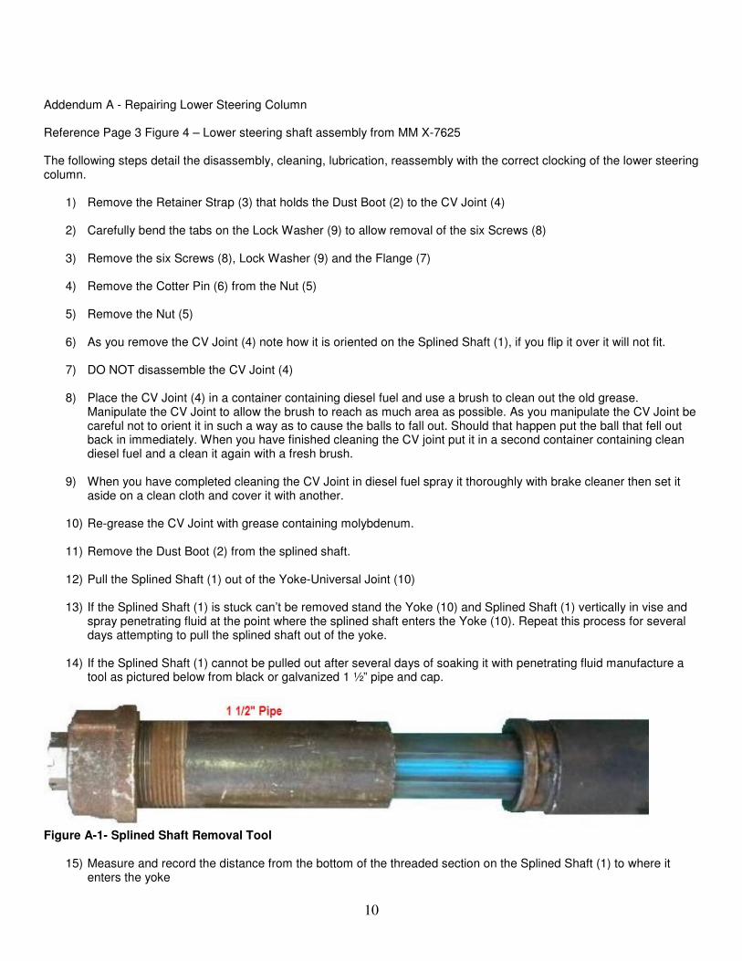
14) If the Splined Shaft (1) cannot be pulled out after several days of soaking it with penetrating fluid manufacture a
tool as pictured below from black or galvanized 1 ½” pipe and cap.
Figure A-1- Splined Shaft Removal Tool
15) Measure and record the distance from the bottom of the threaded section on the Splined Shaft (1) to where it enters the yoke
11
16) Drill a 7/16 inch hole in the pipe cap
17) Lubricate the cap and pipe threads with moly grease and screw the cap onto the pipe finger tight.
18) Cut the pipe / cap to the dimension recorded in step 15) above.
19) De-burr the pipe internally and externally
20) Lubricate the ID of the pipe and OD of the Splined Shaft (1) with Moly grease
21) Slip the pipe and cap over the Splined Shaft (1) and tighten the Nut (5) on the spline shaft exposed threads
22) Clamp the cap in a vice and using a pipe wrench unscrew the pipe from the cap
23) You may need to remove the pipe and cap tool and insert some 1 ½” ID spacers to pull the Splined Shaft (1) out
of the Yoke (10) far enough to be able to pull it by hand.
24) Do not disassemble the Universal Joint