Embed Size (px)
Citation preview
VEHICLE HANDLING IMPROVING BY ACTIVE STEERING
ABDUL HAFIZ BIN AB AZLZ
This Report Submitted to Faculty of Mechanical Engineering to Fulfill Part of Granting Bachelor of Mechanical Engineering (Automotive)
Faculty of Mechanical Engineering
Universiti Teknikal Malaysia Melaka
April 2009
REFERENCE
J Ackerman, T Bunte and D Odenthal, "Advantages of Active Steering for Vehicle Dynamics Control".
Adrian Rodriguez Orozco, "Evaluation of an Active Steering System", Master's Degree Project Stockholm, Sweeden 2004
Said Marnmar and Vahe Badal Baghdassarian, "Two-degree-of-$Feedom Formulation of Vehicle Handling Improvement by ~c t i v e Steerinf, 2000
Jarlrnark J. : Driver-vehicle interaction under influence of crosswind gusts. Lic. Thesis, KTH, Stockholm 2002.
Tom Pilutti, Research Engineer, Galip Ulsoy and Davor Hrovat, "Vehicle Steering Intervention Through Dzrerential Braking", 1 995
Bilin Aksun Guvenc and Levent Guvenc, "The Limited Integrator Model Regulator and Its use in Vehicle Steering Control", 200 1
"I admitted that I have read this paper and in my opinion this paper is enough in terms ofiEqe and quality for granting of Bachelor of Mechanical Engineering (Automotive)"
Signature ..............................
Supervisor : .............................
Date ..............................
"I admitted that this report is my own work except summary and extract the each of them I explained it source"
Signature
Name .................... . j k a v i U A F ~ 8-46 At iz
Date
ABSTRAK
Projek PSM ini menceritakan bagaimana untuk meningkatkan tahap kecekapan
kawalan sesebuah kereta dengan menggunakan aktif stereng hadapan. Active Front
Steering (AFS) adalah teknologi baru yang dicipta untuk kereta penurnpang. Ia
mengandungi elektronik kawalan yang dapat mengawal sudut stereng yang dig&aJ&m
oleh tangan, di mana sudut stereng tersebut ditentukan oleh pernandu. pen&
sudut bebas berlaku berterusan dan bergantung pada situasi pemanduan dan ciri-ciri
tambahan stereng. Di dalarn teknologi Active Steering terdapat satu set si&m gear
yang bercantum dengan tiang stereng. Elekrik motor dalarn sarnbungan akan
membetulkan sudut roda hadapan stereng dalarn kedudukan semasa kelajuan kmderaan.
Aktif stereng h i dinilai dengan menggunakan sistem penyerupam perbezflan input
stereng. Penyelesaian masdah akan dilakukan dalam MatlabISimulink. Model
kenderaan juga dilakukan dalam MatlabISimulink. Di akhir projek ini, system stmeng
akan dapat diketahui dengan lebih mendalam dalam meningkatkan kestabilan k e n d e m
dmipada tergelincir.
ABSTRACT
This PSM project is about improving handling behavior of car by using active
fiont steering. Active Front Steering (AFS) is a newly developed technology for
passenger cars. It provides an electronically controlled superposition of an angle to the
hand steering wheel angle that is prescribed by the driver. This additional degree of
freedom enables a continuous and driving-situation dependent adaptation of the steering
characteristics. At the heart of the new Active Steering system is the planetary gear set
integrated into the steering column. An electric motor in the joint adjusts the front
wheels' steering angle in proportion to the vehicle current speed. This active steering is
evaluated by simulating different steering inputs. The active steering solution has been
implemented in MatlabISimulink. A vehicle model is also implemented in
Matlab/Simulink. This paper focuses on comparison both two systems: a conventional
vehicle and a controlled vehicle. Simulation is made for a constant speed and a specific
changeable road adhesion coefficient. The motivation for this work is to understand and
characterize the response of a vehicle with a complementary steering system. Improved
stability is obtained for the vehicle during slippery road driving.
TABLE OF CONTENT
CHAPTER CONTENT
DECLARATION
ABSTRACT
ABSTRAK
TABLE OF CONTENT
LIST OF TABLE
LIST OF FIGURES
LIST OF APPENDIX
CHAPTER 1 INTRODUCTION
1.1 Project overview
1.2 Objective
1.3 Scope
1.4 Problem statement
PAGE
i
ii
iii
iv
vii
viii
CHAPTER 2 LITERATURE REVIEW
2.1 Basic steering components
2.2 Steering ratio
2.3 Turning circles
2.4 Steering system design
2.4.1 Pitrnan and types
2.4.2 Worm and sector
2.4.3 Worm and roller
2.4.4 Worm and nut
2.4.5 Cam and lever
2.4.6 Rack and pinion
2.4.7 Variable-ratio rack and pinion
2.5 Vehicle dynamic
2.5.1 Understeer
2.5.2 Oversteer
2.5.3 Counter-steering
2.6 Active front steering
2.6.1 Function of AFS
2.7 Yaw motion
2.8 AFS components
2.8.1 The electric and mechanical component
CHAPTER 3 METHODOLOGY
3.1 Flow chart
3.2 Vehicle model
5.3 Single track model
3.4 Subsystem block diagram '
3.5 Control system
3.6 Signal builder
3.7 Parameter
CHAPTER 4 RESULT AND ANALYSIS
4.1 Generate result
4.2 Wind force disturbance
CHAPTER 5 DISCUSSION
5.1 Yaw rate
5.2 Lateral acceleration
5.3 Stability increase
CHAPTER 6 CONCLUSION
6.1 Project conclusion
6.2 Future work
RE-NCES
APPENDIX
LIST OF FIGURE
NO. DESCRIPTION PAGE
Without AFS
With AFS
Steering component
Compound link
Worm sector
Worm and roller
Worm and nut or recirculating ball
Cam and lever
Rack and pinion
Rack and pinion 2
Understeer
Oversteer
Counter-steering
Low speed
Medium to high speed
AFS technology overview
System overview
Front steer angle
Single track model
Vehicle model subsystem
vehicle model subsystem
Modelling of AFS
Signal builder
'Scope' function
Vehicle response
Vehicle response
DIAGRAM PAGE
Diagram 3.1 : Flow chart
CHAPTER 1
INTRODUCTION
This chapter describes a general overview of this research. Background
information related to the topic of active steering and modeling along wit11 project
objectives. Brief literature is reviewed in this section, linking relevant topics to the
research presented here. Finally an objective of the thesis and a brief description in
problem statement are also presented.
1.1 Project overview
An active steering system is a complementary system for a front-steered vehicle
that adds or subtracts a component to the steering signal performed by the driver. The
steering signal from the driver is an angular movement on the steering wheel. The
resulting steering angle is thus composed by the component performed by the driver and
the component contributed by the steering system. The main reason for this is the aim to
improve safety and handling. However it is still difficult to value the improvements. In
this paper one solution is implemented and analyses.
1.2 Objective
1) Characteristic the difference of the response between the controlled and the
uncontrolled vehicle steering for nominal driving and at the limit driving.
2) Have a system with steady state distribution rejection.
3) Stability of the vehicle due to side wind force by reduces yaw rate and lateral
acceleration phase difference.
4) Improve the vehicle handling performance in terms of lateral and yaw motion.
1.3 Scope
The scope for this project is shown below:
Development of Vehicle Handling Model
Develop Active Front Steering Model
Performance evaluation
1.4 Problem statement
Usually for currently car without active front steering (AFS) will hard to control the
car especially when driving with side wind force disturbance. This situation gives the
unwanted yaw to the car. The driver will overcome the unwanted yaw by controlling the
steering angle. This situation was reducing the car comfortable. The new dimension in
steering comfort; active steering offers precision, agility and comfort in every driving
situation.
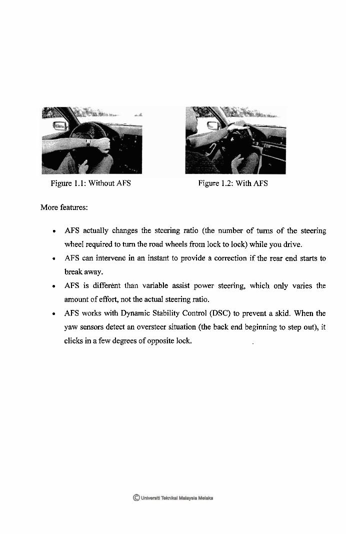
Figtire 1.1 : Without AFS Figure 1.2: With AFS
More features:
AFS actually changes the steering ratio (the number of turns of the steering
wheel required to turn the road wheels fiom lock to lock) while you drive.
AFS can intervene in an instant to provide a correction if the rear end starts to
break away.
AFS is different than variable assist power steering, which only varies the
amount of effort, not the actual steering ratio.
AFS works with Dynamic Stability Control (DSC) to prevent a skid. When the
yaw sensors detect an oversteer situation (the back end beginning to step out), it
clicks in a few degrees of opposite lock.
CHAPTER 2
LITERATURE REVIEW
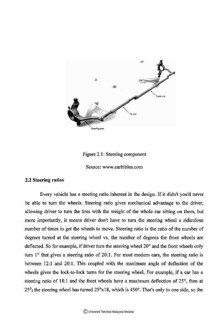
2.1 Basic steering components
The steering system can be one of several designs, which we'll go into further
down the page, but a11 the designs essentially move the track rod left-to-right across the
car. The tie rods connect to the ends of the track rod with ball and socket joints, and then
to the ends of the steering arms, also with ball and socket joints. The purpose of the tie
rods is to allow suspension movement as well as an element of adjustability in the
steering geometry. The tie rod lengths can nornlally be changed to achieve these
different geometries.
Steeiyl arm
Figure 2.1 : Steering component
Source: www.carbib1es.com
2.2 Steering ratios
Every vehicle has a steering ratio inherent in the design. If it didn't you'd never
be able to turn the wheels. Steering ratio gives mechanical advantage to the driver,
allowing driver to turn the tires with the weight of the whole car sitting on them, but
more importantly, it means driver don't have to turn the steering wheel a ridiculous
number of times to get the wheels to move. Steering ratio is the ratio of the number of
degrees turned at the steering wheel vs. the number of degrees the front wheels are
deflected. So for example, if driver turn the steering wheel 20" and the front wheels only
turn l o that gives a steering ratio of 20:l. For most modern cars, the steering ratio is
between 12: 1 and 20: 1. This coupled with the maximum angle of deflection of the
wheels gives the lock-to-lock turns for the steering wheel. For example, if a car has a
steering ratio of 18:l and the fiont wheels have a maximum deflection of 25", then at
25" the steering wheel has turned 25Ox18, which is 450". That's only to one side, so the
entire steering goes from -25" to plus 25" giving a lock-to-lock angle at the steering
wheel of 900°, or 2.5 turns (900" I 360). This works the other way around too of course.
For example if a car is advertised as having a 16:l steering ratio and 3 turns lock-to-
lock, then the steering wheel can turn 1 .5x360° (540") each way. At a ratio of 16:1 that
means the front wheels deflect by 33.75" each way. For racing cars, the steering ratio is
normally much smaller than for passenger cars - i.e. closer to 1: 1 - as the racing drivers
need to get fbller deflection into the steering as quickly as possible.
2.3 Turning circles
The turning circle of a car is the diameter of the circle described by the outside
wheels when turning on full lock. There is no hard and fast formula to calculate the
turning cirele but can get close by using this; turning eircle radius = (tracM2) + (wheelbase/sin(average steer angle)) The numbers required to calculate the turning circle
explain why a classic black London taxi has a tiny 8m turning circle to allow it to do U-
turns in the narrow London streets. In this case, the wheelbase and track aren't radically
different to any other car, but the average steering angle is huge. For comparison, a
typical passenger car turning circle is normally between 1 lm and 13m with SUV turning
circles going out as much as 1 Sm to 17m.
2.4 Steering System designs:
2.4.1 Pitman arm types
There really are only two basie categories of steering system today; those that
have pitman arms with a steering 'box' and those that don't. Older cars and some current
trucks use pitrnan arms. Newer cars and unibody light-duty trucks typically all use some
derivative of rack and pinion steering.
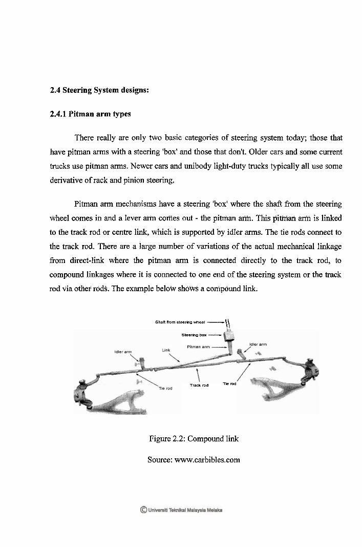
Pitman arm mechanisms have a steering 'box' where the shaft from the steering
wheel comes in and a lever arm comes out - the pitman arm. This pitman arm is linked
to the track rod or centre link, which is supported by idler arms. The tie rods connect to
the track rod. There are a large number of variations of the actual mechanical linkage
from direct-link where the pitman arm is coxlnected directly to the track rod, to
compound linkages where it is connected to one end of the steering system or the track
rod via other rods. The example below shows a compound link.
Shaft from steering hee l -kg t 7
Shering box ---i
Trackmd lied
Figure 2.2: Compound link
Source: www.carbibles.com
Most of the steering box mechanisms that drive the pitrnan arm have a 'dead spot'
in the centre of the steering where can turn the steering wheel a slight amount before the
front wheels start to turn. This slack can normally be adjusted with a screw mechanism
but it can't ever be eliminated. The traditional advantage of these systems is that they
give bigger mechanical advantage and thus work well on heavier vehicles. With the
advent of power steering, that has become a moot point and the steering system design is
now more to do with mechanical design, price and weight. The following are the four
basic types of steering box used in pitman arm systems.
2.4.2 Worm and sector
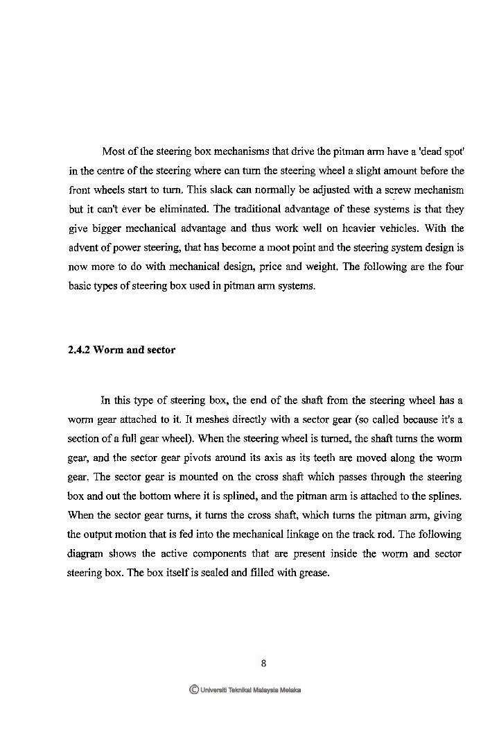
In this type of steering box, the end of the shaft fiom the steering wheel has a
worm gear attached to it. It meshes directly with a seetor gear (so called because it's a
section of a full gear wheel). When the steering wheel is turned, the shaft turns the worm
gear, and the sector gear pivots around its axis as its teeth are moved along the worm
gear. The sector gear is mounted on the cross shaft which passes through the steering
box and out the bottom where it is splined, and the pitman arm is attached to the splines.
When the sector gear turns, it turns the cross shaft, which turns the pitman arm, giving
the output motion that is fed into the mechanical linkage on the track rod. The following
diagram shows the active components that are present inside the worm and sector
steering box. The box itself is sealed and filled with grease.
Shaft lo steer~ng Hiheel
Pitman arm
Figure 2.3: Worm sector
Source: www.carbibles.com
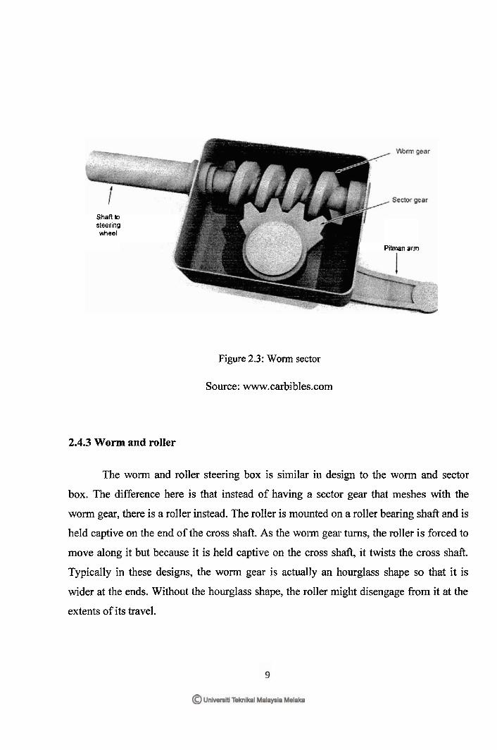
2.4.3 Worm and roller
The worm and roller steering box is similar in design to the worm and sector
box. The difference here is that instead of having a sector gear that meshes with the
worm gear, there is a roller instead. The roller is mounted on a roller bearing shaft md is
held captive on the end of the cross shaft. As the worm gear turns, the roller is forced to
move along it but because it is held captive on the cross shaft, it twists the cross shaft.
Typically in these designs, the worm gear is actually an hourglass shape so that it is
wider at the ends. Without the hourglass shape, the roller might disengage fiom it at the
extents of its travel.
Pitman arm
Figure 2.4: Won% and roller
Source: www.carbibles.com
2.4.4 Worm and nut or recirculating ball
This is by far the most common type of steering box for pitrnan ann systems. In a
recirculating ball steering box, the worm drive has many more turns on it with a finer
pitch. A box or nut is clamped over the worm drive that contains dozens of ball bearings.
These loop around the worm drive and then out into a recirculating channel within the
nut where they are fed back into the worm drive again. As the steering wheel is turned,
the worms drive turns and forces the ball bearings to press against the channel inside the
nut. This forces the nut to move along the worm drive. The nut itself has a couple of
gear teeth cast into the outside of it and these mesh with the teeth on a sector gear which
is attached to the cross shaft just like in the worm and sector mechanism. This system
has much less free play or slack in it than the other designs, hence why it's used the
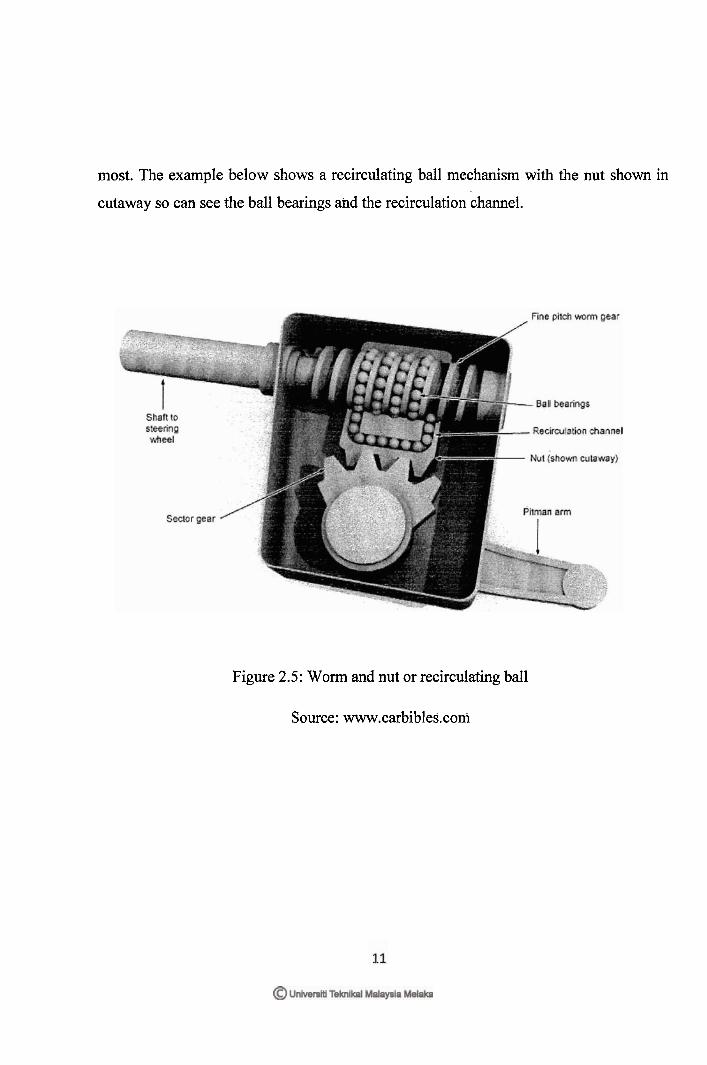
most. The example below shows a recirculating ball mechanism with the nut shown in
cutaway so can see the ball bearings and the recirculation channel.
Figure 2.5: Worm and nut or recirculating ball
Source: www.carbibles.com
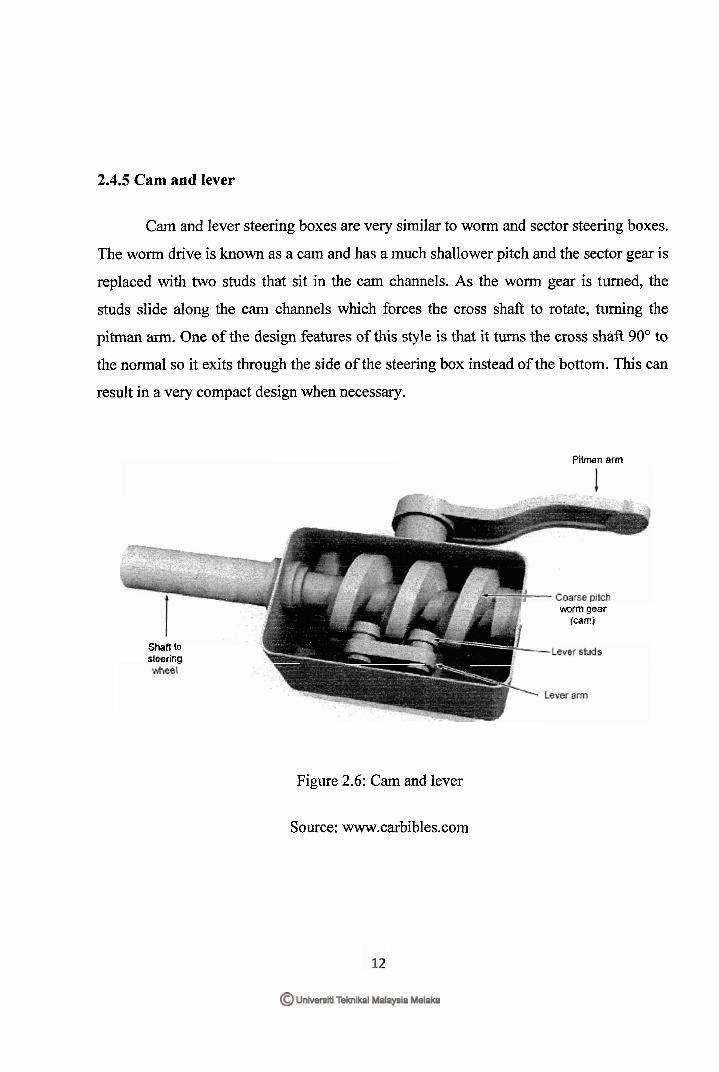
2.4.5 Cam and lever
Cam and lever steering boxes are very similar to worm and sector steering boxes.
The worm drive is known as a cam and has a much shallower pitch and the sector gear is
replaced with two studs that sit in the cam channels. As the worm gear is turned, the
studs slide along the cam channels which forces the cross shafi to rotate, turning the
pitman arm. One of the design features of this style is that it turns the cross shafi 90" to
the normal so it exits through the side of the steering box instead of the bottom. This can
result in a very compact design when necessary.
Pitman arm
Shaft (a
steering
m r m gear (caw)
Figure 2.6: Cam and lever
Source: www.carbibles.com


![Isaac Pitman s Short Isaac Pitman Black and White [Ebooksread.com]](https://img.pdfslide.us/doc/110x75/577cc2f71a28aba71194dba0/isaac-pitman-s-short-isaac-pitman-black-and-white-ebooksreadcom.jpg)