Embed Size (px)
Citation preview
2010 Steelhead Redd Surveys 1 Preliminary Draft – Subject to Revision Protocols and Procedures January 19, 2010
SPECIFIC SAMPLING PROTOCOLS AND PROCEDURES FOR CONDUCTING STEELHEAD REDD SURVEYS DURING THE 2010
SPAWNING SEASON
Yuba River Steelhead Redd Surveys 1.0 RATIONALE Ongoing operation of the Yuba River Development Project (Yuba Project) facilities influences flows and water temperatures in the Yuba River downstream of Englebright Dam and Reservoir. These influences vary both seasonally and geographically, and can act either independently or in combination to affect flow, water temperature, instream habitat, coarse sediment supply and other instream conditions in the lower Yuba River which, in turn, can affect salmonid spawning. A detailed Chinook salmon and steelhead redd survey protocols and procedures was developed by the RMT in August 2009 to guide 2009/2010 redd survey activities. The protocols and procedures presented herein provide an update to the August 2009 redd survey protocols and procedures (which addressed spring-run Chinook salmon, fall-run Chinook salmon and steelhead). This updated protocols and procedures focuses on steelhead spawning, incorporates portions of the August 2009 protocols and procedures for consistency and completeness, and addresses additional considerations, the most important of which are:
(1) Increased sampling frequency
(2) Microhabitat utilization characterization (water depth, velocity and substrate) (3) A revised substrate classification
Although numerous investigations have been conducted on the lower Yuba River, uncertainties remain regarding spawning habitat utilization and the temporal and spatial distribution of steelhead spawning in the lower Yuba River. Steelhead spawning has been reported to generally occur from January through April in the lower Yuba River (CALFED and YCWA 2005; CDFG 1991). However, additional specific information on the temporal and spatial distribution of steelhead redds can be used to gain an improved understanding of the effects of stream flow and water temperature on the time of spawning, spawning site selection, and susceptibility of steelhead redds to scour and dewatering in the lower Yuba River. This updated steelhead redd survey protocols and procedures represents an initial phase of data collection activities, with additional data collection activities to be conducted during subsequent steelhead spawning seasons to obtain a long-term data set. Long-term data sets for steelhead redd characteristics in the lower Yuba River provide an ability to identify trends in spawning
2010 Steelhead Redd Surveys 2 Preliminary Draft – Subject to Revision Protocols and Procedures January 19, 2010
activity as it relates to stream flow and water temperature, and will be useful in the characterization of steelhead spawning microhabitat utilization. This updated 2010 steelhead redd survey protocols and procedures includes obtaining steelhead spawning microhabitat utilization data, building upon and augmenting steelhead spawning microhabitat utilization data previously obtained in the lower Yuba River by CDFG (1991) and USFWS (2008). The USFWS (2008) reported steelhead spawning occurring in deep water areas of the lower Yuba River. This updated 2010 steelhead redd survey protocols and procedures includes surveying areas accessible via the previously determined kayak and wading-based methodology (“Above-Water Surveys”), and also includes surveying deeper water areas (“Underwater Surveys”) during the 2010 survey season. It is anticipated that steelhead redd surveys conducted during subsequent steelhead spawning seasons, as necessary, will include sampling of both above-water and deep water (underwater) habitat in the lower Yuba River. 2.0 OBJECTIVES The overall long-term objective of steelhead redd surveys, of which this 2010 updated steelhead protocols and procedures is a component, is to obtain information contributing to the evaluation of the potential effects of implementation of the Yuba Accord on steelhead spawning activities, and related aquatic habitat conditions in the lower Yuba River. The tasks included as part of the 2010 updated protocols and procedures have several specific objectives, which address the influence of implementation of the Yuba Accord on particular variables (e.g., flow, water temperature) that, in turn, may affect steelhead spawning in the lower Yuba River. These objectives incorporate those identified in the August 2009 protocols and procedures as they pertain to steelhead:
Calculate an annual index of in-river steelhead spawning abundance by enumerating redds, and calculating spawner-to-redd ratios.
Describe and evaluate trends in the temporal and spatial spawning distributions of steelhead.
Identify and describe habitats utilized for spawning by steelhead.
Examine potential relationships between the spatial and temporal distributions of steelhead spawning, and abiotic factors including flow and water temperature.
Compare water temperatures at the time and location of spawning to indices of suitability reported in the literature.
Examine potential inter- and intra-annual trends in the magnitude, and temporal and spatial distribution of steelhead spawning.
Describe and evaluate trends in the magnitude, temporal and spatial distribution of redd superimposition, and compare magnitude of redd superimposition with estimates of steelhead spawning stock escapement.
Obtain steelhead spawning microhabitat utilization data.

2010 Steelhead Redd Surveys 3 Preliminary Draft – Subject to Revision Protocols and Procedures January 19, 2010
Provide additional data contributing to a long-term data set for the evaluation of the potential effects of implementation of the Yuba Accord on steelhead spawning activities, and related aquatic habitat conditions in the lower Yuba River.
3.0 SURVEY DESIGN 3.1 Survey Location The lower Yuba River extends about 38.6 km (24 mi) from Englebright Dam, the first impassible fish barrier on the river, downstream to the confluence with the Feather River near Marysville, California. Approximately 33.6 km (20.9 mi) of the 38.6 km (24 mi) of the total length of the lower Yuba River will be surveyed during the 2010 steelhead redd surveys. About 1.1 km (0.7 mi) of the lower Yuba River located immediately below the first set of riffles downstream of Deer Creek to the top of Narrows Pool will not be surveyed due to rugged and dangerous conditions in the steep canyon known as the Narrows. Additionally, an approximate 3.2 km (2 mi) section of the lower Yuba River from Simpson Lane Bridge to the confluence with the Feather River will not be regularly surveyed because redds have not been observed during past surveys. The area of the lower Yuba River to be surveyed for redds includes four major sections (Table 1). Table 1. Lower Yuba River redd survey sections. Sections Location Kilometers (Miles) 1 Englebright Dam to 1st set of riffles below Deer
Creek 1.4 0.9 2 Narrows Pool to SR 20 Bridge 6.4 4.0 3 SR 20 Bridge to Daguerre Point Dam 9.7 6.0 4 Daguerre Point Dam to Simpson Lane Bridge 16.1 10.0 Total 32.2 20.9
3.2 Survey Period With implementation of the Yuba Accord, the steelhead redd surveys will be considered a long-term monitoring effort. Steelhead redd surveys are anticipated to be conducted annually for at least five years, from 2009/2010 through 2013/2014. The RMT will review the data and reports on an annual basis, and determine whether the overall duration of the redd surveys should be adjusted. During the 2010 steelhead spawning season, redd surveys will begin mid- to late-January 2010 and extend through about May 1 (or until newly constructed redds are no longer observed). 3.3 Sampling Frequency The 2010 steelhead redd surveys will be conducted weekly from mid- to late-January 2010 and extend through about May 1 (or until newly constructed redds are no longer observed).
2010 Steelhead Redd Surveys 4 Preliminary Draft – Subject to Revision Protocols and Procedures January 19, 2010
3.4 Sample Size For estimates of total abundance, spatial and temporal distribution of steelhead redds, the sample size for the steelhead redd surveys is the number of weekly surveys conducted for the entire survey season. 4.0 SURVEY PROTOCOLS AND PROCEDURES 4.1 Pre-survey Planning Pre-survey preparations include: (1) developing the seasonal survey schedule; (2) obtaining all necessary equipment; and (3) training all survey personnel. A planning meeting will be held with the RMT to review the survey procedures and logistics. The purpose of this meeting is two-fold: (1) to verify that all necessary preparations and planning arrangements have been completed for the 2010 steelhead redd survey season; and (2) to provide an opportunity to make adjustments to the survey timing, logistics or approach if new information becomes available or if deemed necessary by the RMT. 4.2 Data Collection and Sampling Techniques 4.2.1 Redd Location Prior to conducting a survey, the following data will be recorded: (1) survey date; (2) surveyors’ initials; (3) survey section; (4) number of crews; (5) specific crew identification (Crew A or B); (6) weather; (7) streamflow (cfs); and (8) secchi disk depth (ft). Flow data will be obtained from the Yuba River Smartsville and Marysville gages through the California Department of Water Resources’ (CDWR) online California Data Exchange Center (CDEC). The Smartsville gage will be used for flows above Daguerre Point Dam (DPD) and the Marysville gage for flows below DPD. The accuracy of reported flows at these gages will be periodically verified. Each observed redd will be consecutively numbered from the very first redd observed during the steelhead redd survey through the entire redd sampling season. For each new redd observed throughout the sampling season, the following data will be recorded: (1) a GPS (Trimble GeoExplorer XT) location taken at the center of the redd’s pit with a unique identifying number (i.e., Date + plus redd number; e.g. 011510-001); (2) the time of observation; (3) total dimensional area (using a GPS) for areas appearing to contain multiple redds with no clear boundaries (i.e., mass aggregate spawning); (4) habitat type (i.e., pool, riffle, run, or glide); (5) redd species identification; (6) species, number and estimated lengths of fish observed on the redd; (7) location information (i.e., side channel or main channel and distance to unique fluvial geomorphologic features such as “riffle-crest”); (8) comments regarding observable redd superimposition (i.e., redd overlap); and (9) any additional comments. The path undertaken by each surveyor down the river will be recorded using Garmin GPSMAP 60Cx GPS units to document specific locations of the river surveyed.
2010 Steelhead Redd Surveys 5 Preliminary Draft – Subject to Revision Protocols and Procedures January 19, 2010
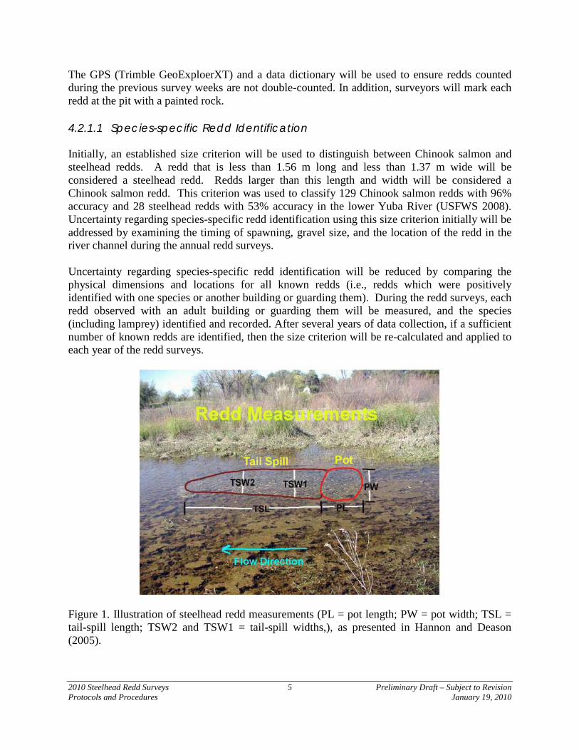
The GPS (Trimble GeoExploerXT) and a data dictionary will be used to ensure redds counted during the previous survey weeks are not double-counted. In addition, surveyors will mark each redd at the pit with a painted rock. 4.2.1.1 Species-specific Redd Identification Initially, an established size criterion will be used to distinguish between Chinook salmon and steelhead redds. A redd that is less than 1.56 m long and less than 1.37 m wide will be considered a steelhead redd. Redds larger than this length and width will be considered a Chinook salmon redd. This criterion was used to classify 129 Chinook salmon redds with 96% accuracy and 28 steelhead redds with 53% accuracy in the lower Yuba River (USFWS 2008). Uncertainty regarding species-specific redd identification using this size criterion initially will be addressed by examining the timing of spawning, gravel size, and the location of the redd in the river channel during the annual redd surveys. Uncertainty regarding species-specific redd identification will be reduced by comparing the physical dimensions and locations for all known redds (i.e., redds which were positively identified with one species or another building or guarding them). During the redd surveys, each redd observed with an adult building or guarding them will be measured, and the species (including lamprey) identified and recorded. After several years of data collection, if a sufficient number of known redds are identified, then the size criterion will be re-calculated and applied to each year of the redd surveys.
Figure 1. Illustration of steelhead redd measurements (PL = pot length; PW = pot width; TSL = tail-spill length; TSW2 and TSW1 = tail-spill widths,), as presented in Hannon and Deason (2005).
2010 Steelhead Redd Surveys 6 Preliminary Draft – Subject to Revision Protocols and Procedures January 19, 2010
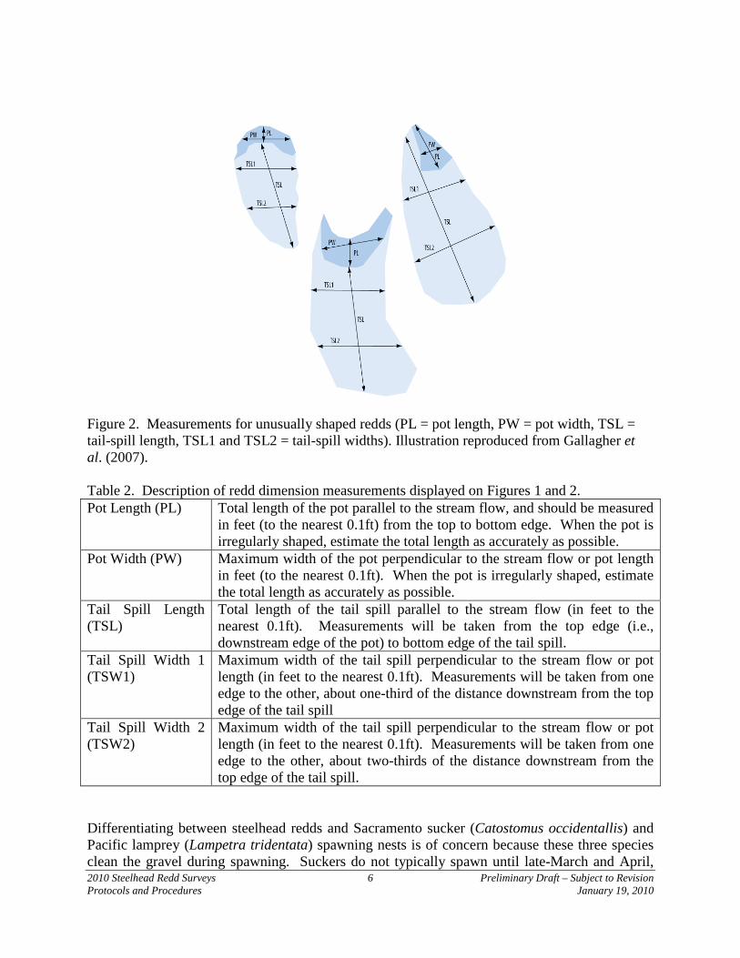
Figure 2. Measurements for unusually shaped redds (PL = pot length, PW = pot width, TSL = tail-spill length, TSL1 and TSL2 = tail-spill widths). Illustration reproduced from Gallagher et al. (2007). Table 2. Description of redd dimension measurements displayed on Figures 1 and 2. Pot Length (PL) Total length of the pot parallel to the stream flow, and should be measured
in feet (to the nearest 0.1ft) from the top to bottom edge. When the pot is irregularly shaped, estimate the total length as accurately as possible.
Pot Width (PW) Maximum width of the pot perpendicular to the stream flow or pot length in feet (to the nearest 0.1ft). When the pot is irregularly shaped, estimate the total length as accurately as possible.
Tail Spill Length (TSL)
Total length of the tail spill parallel to the stream flow (in feet to the nearest 0.1ft). Measurements will be taken from the top edge (i.e., downstream edge of the pot) to bottom edge of the tail spill.
Tail Spill Width 1 (TSW1)
Maximum width of the tail spill perpendicular to the stream flow or pot length (in feet to the nearest 0.1ft). Measurements will be taken from one edge to the other, about one-third of the distance downstream from the top edge of the tail spill
Tail Spill Width 2 (TSW2)
Maximum width of the tail spill perpendicular to the stream flow or pot length (in feet to the nearest 0.1ft). Measurements will be taken from one edge to the other, about two-thirds of the distance downstream from the top edge of the tail spill.
Differentiating between steelhead redds and Sacramento sucker (Catostomus occidentallis) and Pacific lamprey (Lampetra tridentata) spawning nests is of concern because these three species clean the gravel during spawning. Suckers do not typically spawn until late-March and April,
2010 Steelhead Redd Surveys 7 Preliminary Draft – Subject to Revision Protocols and Procedures January 19, 2010
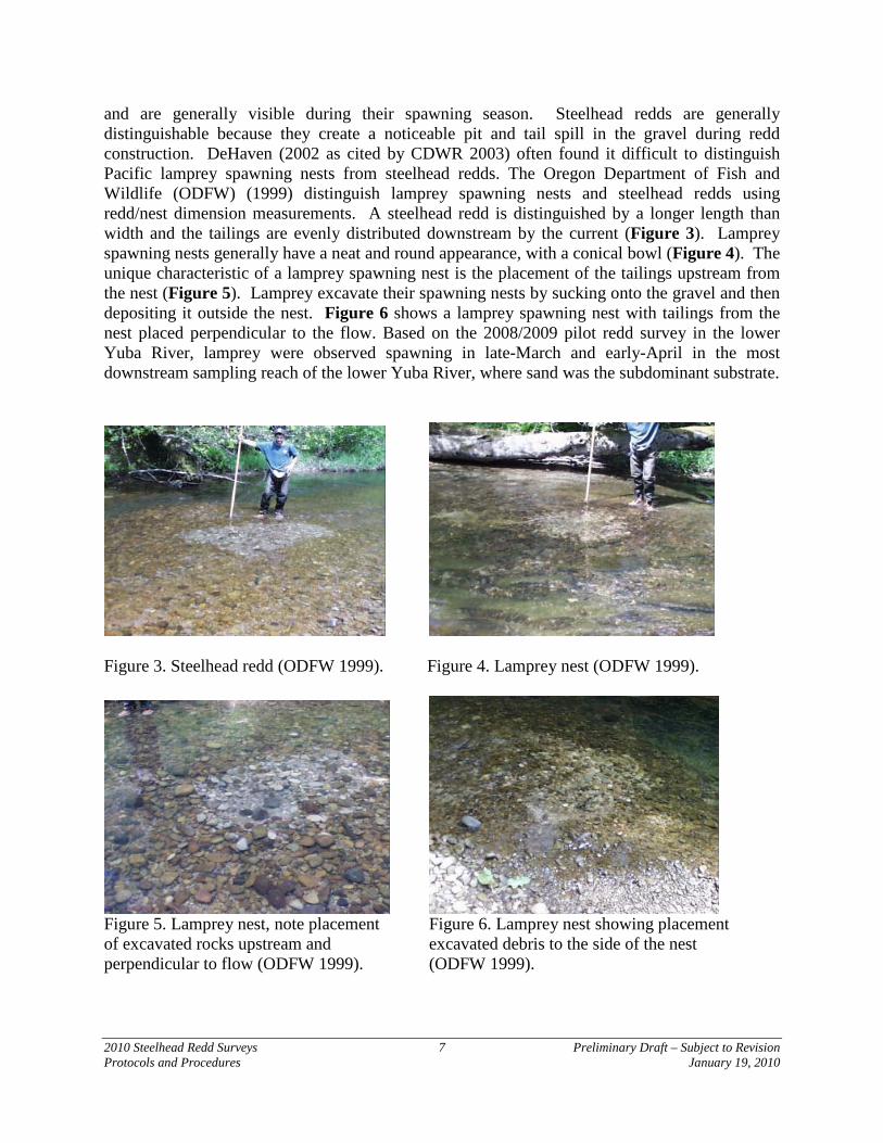
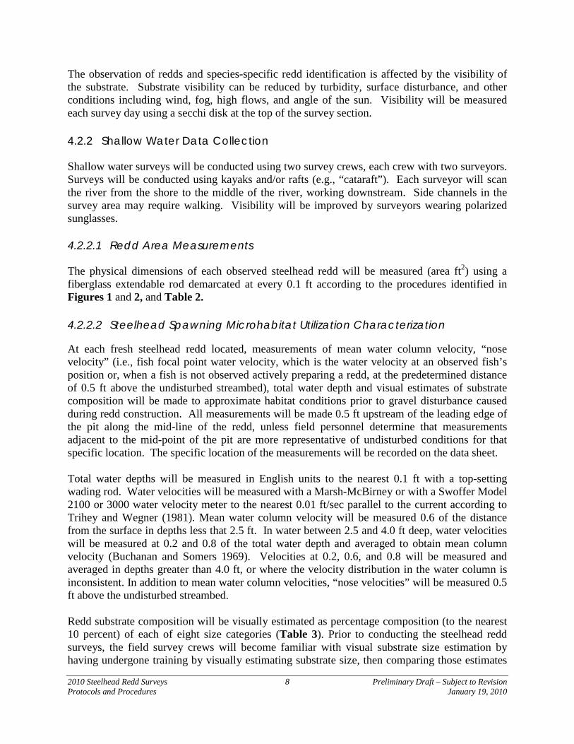
and are generally visible during their spawning season. Steelhead redds are generally distinguishable because they create a noticeable pit and tail spill in the gravel during redd construction. DeHaven (2002 as cited by CDWR 2003) often found it difficult to distinguish Pacific lamprey spawning nests from steelhead redds. The Oregon Department of Fish and Wildlife (ODFW) (1999) distinguish lamprey spawning nests and steelhead redds using redd/nest dimension measurements. A steelhead redd is distinguished by a longer length than width and the tailings are evenly distributed downstream by the current (Figure 3). Lamprey spawning nests generally have a neat and round appearance, with a conical bowl (Figure 4). The unique characteristic of a lamprey spawning nest is the placement of the tailings upstream from the nest (Figure 5). Lamprey excavate their spawning nests by sucking onto the gravel and then depositing it outside the nest. Figure 6 shows a lamprey spawning nest with tailings from the nest placed perpendicular to the flow. Based on the 2008/2009 pilot redd survey in the lower Yuba River, lamprey were observed spawning in late-March and early-April in the most downstream sampling reach of the lower Yuba River, where sand was the subdominant substrate.
Figure 3. Steelhead redd (ODFW 1999). Figure 4. Lamprey nest (ODFW 1999).
Figure 5. Lamprey nest, note placement Figure 6. Lamprey nest showing placement of excavated rocks upstream and excavated debris to the side of the nest perpendicular to flow (ODFW 1999). (ODFW 1999).
2010 Steelhead Redd Surveys 8 Preliminary Draft – Subject to Revision Protocols and Procedures January 19, 2010
The observation of redds and species-specific redd identification is affected by the visibility of the substrate. Substrate visibility can be reduced by turbidity, surface disturbance, and other conditions including wind, fog, high flows, and angle of the sun. Visibility will be measured each survey day using a secchi disk at the top of the survey section.
4.2.2 Shallow Water Data Collection Shallow water surveys will be conducted using two survey crews, each crew with two surveyors. Surveys will be conducted using kayaks and/or rafts (e.g., “cataraft”). Each surveyor will scan the river from the shore to the middle of the river, working downstream. Side channels in the survey area may require walking. Visibility will be improved by surveyors wearing polarized sunglasses. 4.2.2.1 Redd Area Measurements The physical dimensions of each observed steelhead redd will be measured (area ft2) using a fiberglass extendable rod demarcated at every 0.1 ft according to the procedures identified in Figures 1 and 2, and Table 2.
4.2.2.2 Steelhead Spawning Microhabitat Utilization Characterization
At each fresh steelhead redd located, measurements of mean water column velocity, “nose velocity” (i.e., fish focal point water velocity, which is the water velocity at an observed fish’s position or, when a fish is not observed actively preparing a redd, at the predetermined distance of 0.5 ft above the undisturbed streambed), total water depth and visual estimates of substrate composition will be made to approximate habitat conditions prior to gravel disturbance caused during redd construction. All measurements will be made 0.5 ft upstream of the leading edge of the pit along the mid-line of the redd, unless field personnel determine that measurements adjacent to the mid-point of the pit are more representative of undisturbed conditions for that specific location. The specific location of the measurements will be recorded on the data sheet. Total water depths will be measured in English units to the nearest 0.1 ft with a top-setting wading rod. Water velocities will be measured with a Marsh-McBirney or with a Swoffer Model 2100 or 3000 water velocity meter to the nearest 0.01 ft/sec parallel to the current according to Trihey and Wegner (1981). Mean water column velocity will be measured 0.6 of the distance from the surface in depths less that 2.5 ft. In water between 2.5 and 4.0 ft deep, water velocities will be measured at 0.2 and 0.8 of the total water depth and averaged to obtain mean column velocity (Buchanan and Somers 1969). Velocities at 0.2, 0.6, and 0.8 will be measured and averaged in depths greater than 4.0 ft, or where the velocity distribution in the water column is inconsistent. In addition to mean water column velocities, “nose velocities” will be measured 0.5 ft above the undisturbed streambed. Redd substrate composition will be visually estimated as percentage composition (to the nearest 10 percent) of each of eight size categories (Table 3). Prior to conducting the steelhead redd surveys, the field survey crews will become familiar with visual substrate size estimation by having undergone training by visually estimating substrate size, then comparing those estimates
2010 Steelhead Redd Surveys 9 Preliminary Draft – Subject to Revision Protocols and Procedures January 19, 2010
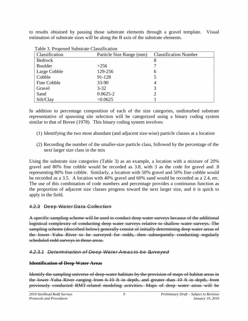
to results obtained by passing those substrate elements through a gravel template. Visual estimation of substrate sizes will be along the B axis of the substrate elements. Table 3. Proposed Substrate Classification
Classification Particle Size Range (mm) Classification Number Bedrock Boulder Large Cobble
>256 129-256
8 7 6
Cobble 91-128 5 Fine Cobble Gravel
33-90 3-32
4 3
Sand 0.0625-2 2 Silt/Clay <0.0625 1
In addition to percentage composition of each of the size categories, undisturbed substrate representative of spawning site selection will be categorized using a binary coding system similar to that of Bovee (1978). This binary coding system involves:
(1) Identifying the two most abundant (and adjacent size-wise) particle classes at a location
(2) Recording the number of the smaller-size particle class, followed by the percentage of the next larger size class in the mix
Using the substrate size categories (Table 3) as an example, a location with a mixture of 20% gravel and 80% fine cobble would be recorded as 3.8, with 3 as the code for gravel and .8 representing 80% fine cobble. Similarly, a location with 50% gravel and 50% fine cobble would be recorded as a 3.5. A location with 40% gravel and 60% sand would be recorded as a 2.4, etc. The use of this combination of code numbers and percentage provides a continuous function as the proportion of adjacent size classes progress toward the next larger size, and it is quick to apply in the field. 4.2.3 Deep Water Data Collection
A specific sampling scheme will be used to conduct deep water surveys because of the additional logistical complexity of conducting deep water surveys relative to shallow water surveys. The sampling scheme (described below) generally consist of initially determining deep water areas of the lower Yuba River to be surveyed for redds, then subsequently conducting regularly scheduled redd surveys in those areas. 4.2.3.1 Determination of Deep Water Areas to be Surveyed Identification of Deep Water Areas Identify the sampling universe of deep-water habitats by the provision of maps of habitat areas in the lower Yuba River ranging from 6-10 ft in depth, and greater than 10 ft in depth, from previously conducted RMT-related modeling activities. Maps of deep water areas will be
2010 Steelhead Redd Surveys 10 Preliminary Draft – Subject to Revision Protocols and Procedures January 19, 2010
developed by preparation of a riverbed topographic map derived from the ArcGIS raster files from the digital elevation model, preparation of a water surface elevation topographic map derived either from the ArcGIS raster files from the SRH2D 2-dimensional hydraulic model (at a flow of approximately 750 cfs) or from the LIDAR observational data of the water surface elevation (at a flow of approximately 820 cfs), then differencing the raster files to obtain water depths. The resultant deep water area maps will be classified into water depth intervals (i.e., 0 - 6.0 ft, 6.1 – 10.0 ft, 10.1 – 12.0 ft, and > 12.0 ft). Areas corresponding to each of these water depth intervals will be indicated on a base map of the lower Yuba River. Delineation of Suitable Substrate in Deep Water Areas
Referencing the deep water area base map (described in the preceding step), the field crew will navigate via jet boat to the areas demarcated on the map comprised of water depths > 6.0 ft, then utilize fathometer readings to determine specific locations of each deep water (i.e., > 6.0 ft) area to be examined. The substrate sizes presented in Table 3 corresponding to gravel, fine cobble, and cobble size classes (ranging from 3 – 128 mm, or 0.1 – 5 inches) encompass the range of particle sizes reported to be utilized by spawning steelhead, and will be the focus of the deep-water potential spawning area mapping. Regarding substrate composition, a potentially “spawnable” area will be defined as those areas characterized by a predominance of gravel (3 - 32 mm), fine cobble (33 - 90 mm), or cobble (91 - 128 mm). An initial substrate survey effort will be conducted (described below) to examine whether deep water areas contain patches of substrate suitable for spawning. The initial surveys will identify deep water areas characterized by surface substrate within the broad range (i.e., 3 – 128 mm) of suitable spawning substrate, recording the dominant and subdominant substrate sizes corresponding to the size categories in Table 3, as well as percent fines. Areas comprised of suitable spawning substrate will be retained as part of the sampling universe of deep water habitats for redd surveys subsequent to the initial survey effort. Examination of the riverbed in deep water areas during the initial surveys will be accomplished by a combination of direct and indirect observation techniques. Direct observation techniques include the use of boat-mounted view tubes and snorkeling in moderate depth areas (where the bottom is clearly visible from the surface), or with SCUBA in deeper areas (if deemed more efficient and safe). Direct observation survey methods consist of entering the river upstream of the area to be surveyed, floating through the area to the downstream boundary, and repeating this process in parallel tracks until the entire habitat area has been examined. In areas characterized by relatively slow surface water velocities, the snorkeler(s) may work independently of the jet boat (to identify boundaries), and in areas characterized by relatively fast surface water velocities a snorkeler may occupy a small pontoon raft tethered to the boat for more rapid marking of substrate boundaries. If the surveys are being conducted by snorkeling or SCUBA diving, then the surveyors will define suitable spawning substrate boundaries by placing markers (weights with floats), then subsequently having the jet boat crew take GPS coordinates directly over the boundary markers. Substrate characterization by view tubes, snorkel or SCUBA divers will be conducted by personnel trained in substrate size estimation using the previously described gravel template training process.
2010 Steelhead Redd Surveys 11 Preliminary Draft – Subject to Revision Protocols and Procedures January 19, 2010
If surface water velocities are too fast to allow thorough examination of the area being surveyed by the boat-mounted view tube, then it is anticipated that this direct observation survey method will consist of entering the river downstream of the area to be surveyed and powering the jet boat upstream in parallel tracks until the entire habitat area has been examined. If substrate boundaries are located using the boat-mounted view tube, then boundary locations will be marked by taking GPS waypoints directly over the identified boundaries. Indirect observation techniques include the use of a boom-mounted underwater video camera. Video surveying will utilize a commercial-grade, high-resolution, low-lux underwater video camera (Outland Technology UWC-300, http://www.outlandtech.com/oticam.htm), suspended from the bow of the boat using a weight-and-winch system, and viewed via an onboard laptop or a portable viewer (Archos AV-700 mini digital recorder). Video-based surveying will incorporate a ruler mounted below the camera to assist in the characterization of substrate sizes. Video surveys will be digitally recorded for later QA/QC purposes. GPS waypoints will be collected at the boundaries of each spawning area while traversing the area by jet-boat during underwater video surveys. Specific streambed substrate surveying techniques and methods to be used in each deep water habitat area will be determined following initial on-site testing of the suite of previously described techniques and methods. Regardless of the specific surveying techniques and methods employed at each deep water area, GPS coordinates of the waypoints of suitable spawning substrate boundaries (i.e., transitions between relatively homogenous patches of substrate particle size composition within the 3 - 128 mm range) will be recorded using either a Trimble Pathfinder Pro XRS submeter GPS (with Omnistar correction), or a Trimble GeoExploerXT handheld GPS. Substrate boundary waypoints will be used to develop polygons of deep water areas characterized by streambed surface substrate within the broad range of suitable spawning substrate (i.e., 3 - 128 mm) areas, and the polygons will be transferred to a base map of the lower Yuba River to identify areas to be included in subsequent redd surveys. Non-spawnable areas dominated by silt/clay or sand, as well as large cobble, boulders or bedrock, will be noted as encountered but will not be specifically delineated and mapped. 4.2.3.2 Deep Water Redd Surveys Deep water redd surveys will be conducted at regularly scheduled intervals (approximately weekly, depending upon logistical feasibility) from late January through about May 1, 2010 (or until newly constructed redds are no longer observed). Referencing the base map, the field crew will navigate (using GPS) the jet boat to the polygons depicting deep water areas characterized by the broad range (i.e., 3 – 128 mm) of suitable spawning substrate. Prior to conducting each deep water redd survey, the following data will be recorded: (1) survey date; (2) surveyors’ initials; (3) survey polygon identification on the reference map; (4) number of surveyors; (5) specific survey methods and techniques; (6) weather; (7) streamflow (cfs); and (8) secchi disk depth (ft).
2010 Steelhead Redd Surveys 12 Preliminary Draft – Subject to Revision Protocols and Procedures January 19, 2010
Areas delineated by the polygons will be systematically surveyed for redds using the direct and indirect deep water methods and techniques described in Section 4.2.3.1, and conducting the following specific data collection activities. At each newly constructed redd located during the deep water surveys, a painted lead marker will be dropped into the pit of the redd to minimize the potential for repeat measurements at previously constructed and measured redds. If a redd is located using the boat-mounted view tube, or by using underwater videography, then the redd location will be marked by taking GPS coordinates directly over the redd location. If a redd is located using snorkel or SCUBA, then the divers will direct the jet boat such that GPS coordinates are taken directly over the redd location. GPS coordinates of redd locations will be recorded using either a Trimble Pathfinder Pro XRS submeter GPS (with Omnistar correction), or a Trimble GeoExploerXT handheld GPS).
Redd characteristics will be measured to approximate habitat conditions prior to gravel disturbance caused during redd construction. All measurements will be made 0.5 ft upstream of the leading edge of the pit along the mid-line of the redd, unless field personnel determine that measurements adjacent to the mid-point of the pit are more representative of undisturbed conditions for that specific location. The specific location of the measurements will be recorded on the data sheet. Total water depths will be measured to the nearest 0.1 ft using the jet boat fathometer. Water velocities will be measured using a Marsh-McBirney or with a Swoffer Model 2100 or 3000 water velocity meter (to the nearest 0.01 ft/sec parallel to the current according to Trihey and Wegner 1981), suspended from the boat by a weight-and-winch system, or by using an ADCP meter. Mean water column velocity will be measured at 0.2, 0.6, and 0.8 of the distance from the surface and averaged to obtain mean column velocity (Buchanan and Somers 1969). In addition to mean water column velocities, “nose velocities” will be measured 0.5 ft above the undisturbed streambed. Redd substrate composition will be visually estimated (to the nearest 10 percent) of each of the eight size categories presented in Table 3, depending upon the logistical difficulties of estimating percentage composition while conducting deep water surveys. At a minimum, undisturbed substrate representative of spawning site selection will be categorized using the binary coding system described in Section 4.2.2.2. Each redd observed during the deep water surveys will be consecutively numbered from the very first redd observed through the entire redd sampling season. For each new redd observed throughout the sampling season, the following data will be recorded: (1) a GPS (using either a Trimble Pathfinder Pro XRS submeter GPS (with Omnistar correction), or a Trimble GeoExploerXT handheld GPS) location taken at the center of the redd’s pit with a unique identifying number (i.e., Date + plus redd number; e.g. 011510-001); (2) the time of observation; (3) total dimensional area (using a GPS) for areas appearing to contain multiple redds with no clear boundaries (i.e., mass aggregate spawning); (4) habitat type (i.e., pool, run, or glide); (5) redd species identification; (6) species, number and estimated length of fish observed on the
2010 Steelhead Redd Surveys 13 Preliminary Draft – Subject to Revision Protocols and Procedures January 19, 2010
redd; (7) location information (i.e., head of pool, tail of pool, transitional area); (8) estimates of redd area (length by average width); (9) comments regarding observable redd superimposition (i.e., redd overlap); and (10) any additional comments. 4.3 Field Gear Decontamination New Zealand mudsnails (Potamopyrgus antipodarum, NZMS) were first discovered in California (Owens River) in 1999. The NZMS has the ability to adapt to new ecosystems and alter food web dynamics. Controlling the spread of the NZMS is a top priority for the California Department of Fish and Game. CDFG needs to ensure that their employees are not spreading NZMS in the course of carrying out their duties. Therefore, a field gear decontamination protocol for NZMS has been developed and will be used for gear used in the lower Yuba River. The following procedures for decontaminating field gear (i.e., waders, wading boots, boot insoles, nets, wading sticks, or anything else that comes into contact with the water) developed by CDFG (2008) will be followed prior to entering a new body of water or at the end of the day, whichever occurs first. Freezing field gear will be the first option if a freezer is available. Freezing has no adverse effect on field gear or on the environment, and is the most cost effective means of decontamination. 4.3.1 Freezing Procedure Place field gear into a new large plastic bag and seal before placing into the vehicle. Any surface that comes in contact with field gear can become contaminated. Upon returning to a CDFG office, place the plastic bag containing the field gear into a freezer (<0 °C) for a minimum of six hours. 4.3.2 Immersion Procedure 1) If field gear is not going to be decontaminated on site, place the field gear into a new
large plastic bag and seal before placing into the vehicle.
2) Place all field gear that came in contact with water into a container of sufficient size to allow gear to be completely immersed in decontamination solution.
3) Pour decontamination solution (5% Sparquat) into container to allow complete immersion of all field gear. If necessary, weigh down the gear to ensure the gear is completely immersed. To make the decontamination solution, use a ratio of 7 oz of Sparquat to 1 gallon of water.
4) Soak field gear in decontamination solution for a minimum of 15 minutes. 5) Remove field gear from the decontamination solution and inspect gear to ensure that all
debris that could contain NZMS has been removed. Use a stiff brush to remove any debris that remains on the field gear.
2010 Steelhead Redd Surveys 14 Preliminary Draft – Subject to Revision Protocols and Procedures January 19, 2010
6) Rinse field gear with fresh water. Do not use water from the sampling site. Using water
from the sampling site will contaminate your field gear. Rinse water should not be allowed to enter a storm drain or water body.
7) Decontamination solution must be disposed of into a sanitary fill for proper waste treatment. Decontamination solution cannot be dumped on the ground under any circumstances. Decontamination solution cannot be disposed into a septic system. Five- gallon disposal containers will be provided to personnel for use in disposing decontamination solution. Decontamination solution can be disposed of at the CDFG Regional office.
4.3.3 Spray Bottle Procedure 1) Create a decontamination solution that contains 10% Sparquat (900ml of water and
100ml of Sparquat).
2) Liberally spray field gear until gear is completely saturated. Ensure that hard to reach areas are sprayed thoroughly.
3) Allow decontamination solution to remain on field gear for a minimum of 15 minutes.
4) Rinse sampling gear with fresh water. Do not use water from the sampling site. Using water from the sampling site will contaminate the field gear.
5) Rinse water should not be allowed to enter a storm drain or water body.
6) The spray bottle procedure should not be used except under very extreme circumstances when freezing or immersion procedures cannot be completed. Contact time and concentration of decontamination solution from spray bottle procedures cannot be guaranteed, which does not ensure 100% mortality of NZMS.
4.4 Watercraft Decontamination
California’s waterways currently face the challenge of invasion by quagga mussels (Dreissena bugensis) and zebra mussels (Dreissena polymorpha). Zebra mussels, a species native to Eastern Europe, were first introduced in the United States through ballast water released into the Great Lakes in the late 1980s. Quagga mussels soon followed. In January 2007, quagga mussels were discovered in Lake Mead and later in the Colorado River. They now infest water bodies in Riverside, San Diego and Orange counties. In January 2008, zebra mussels were discovered in the San Justo Reservoir in San Benito County. Preventing the spread of quagga and zebra mussels is a top priority for CDFG. CDFG needs to ensure that their employees are not spreading quagga and zebra mussels in the course of carrying out their duties. Therefore, the following watercraft decontamination protocol for quagga and
2010 Steelhead Redd Surveys 15 Preliminary Draft – Subject to Revision Protocols and Procedures January 19, 2010
zebra mussels has been developed for immediate implementation by all CDFG employees (CDFG 2008). 1) Prior to leaving the launch facility; remove all plants and mud from the watercraft, trailer,
and equipment. Dispose of all material in the trash.
2) Prior to leaving the launch facility; drain all water from the watercraft and dry all areas, including the motor, motor cooling system, live wells, bilges, and lower end unit.
3) Upon return to Regional facilities or local office, pressure wash the watercraft and trailer with 140 °F water, including all of the boat equipment (i.e., ropes, anchors, etc.) that came into contact with the water. (Pressure washers are available at the Region office for boat decontamination.)
4) Flush the engine with 140 °F water for at least 10 minutes and run 140 °F water through the live wells, bilges, and all other areas that could contain water.
5) For areas that cannot be washed, but have come into contact with the water, spray or wipe the areas with a solution of 4% muriatic acid.
6) Wash all field gear with 140 °F water or a decontamination solution that contains a 6% chlorine solution.
7) To ensure 100% mortality the water needs to be 140 °F at the point of contact or 155 °F at the nozzle.
Anyone with questions regarding the acquisition of chemicals, require proper training to implement these protocols, or need a field gear decontamination kit, call (916) 358-2895 (Mr. Jason Roberts; CDFG; Environmental Scientist) or (916) 358-2943 (Mr. Joseph Johnson; CDFG; Senior Environmental Scientist). 4.5 Quality Assurance/Quality Control Processes A chain of custody and review process will occur for all data sheets. Surveyors in the field will review data sheets to verify all data has been collected, and they will record their initials on all data sheets and place them into a “data to be entered” binder. Subsequently, personnel that enter the data into a database will date and initial the data sheets and place them into an “entered data” binder. Following this, personnel will complete a final review the data entered into the database against the data sheets for quality assurance/quality control purposes and initial and date the bottom of the data sheet. Although handheld GPS data recorders will be used in the field, a paper copy of the data will also be collected in the field and used to check the GPS data for errors.
2010 Steelhead Redd Surveys 16 Preliminary Draft – Subject to Revision Protocols and Procedures January 19, 2010
5.0 LOGISTICS 5.1 Personnel Redd survey personnel will be responsible for conducting redd surveys according to this protocols and procedures. Copies of this protocols and procedures will be provided to all survey personnel prior to the onset of field data collection activities. All survey personnel will be expected to maintain complete survey field notes per this protocols and procedures. 5.2 Qualifications To successfully complete data collection associated with this study, the lead personnel conducting the work will have the following minimum qualifications: a related 4-year college degree (e.g., fisheries biology or biology) and a minimum of 2 years of professional experience in fisheries field surveys. Specifically, personnel will have experience with:
Use of various fish and fish habitat sampling techniques
Use of aerial photographs as a field mapping base
Use of GPS equipment
Design and analysis of biological field studies
The data collection methods will be conducted by two person (minimum) monitoring teams to facilitate safe and efficient data collection. At least one of the team members of the monitoring team will have the minimum qualifications as stated above and will be conducting the survey. Redd survey personnel should be in such physical shape as to allow for extended and at times strenuous hiking while carrying equipment and personal gear that may weigh 20 pounds or more. Personnel must be able to swim. Survey personnel should expect to work extended daily hours as necessary to complete described surveys. Prior to the initiation of survey work, all survey personnel will have had to complete several training sessions on field collection techniques and safety. All necessary training will be provided during the preseason preparation and training period. 5.2.1 Training This protocols and procedures will be available to all redd survey personnel to promote consistency among survey efforts and to address safety concerns. New hires will be scheduled to go on surveys with experienced redd survey personnel and receive training in the field. Safety, aspects of landowner relations, trespassing regulations, and redd count protocol training for all survey crew members will be scheduled and conducted prior to initiating the field season. Safety training for field crews will include first aid, wilderness medicine, swift water rescue training, boat safety, and wader safety training. Specialized training for using all-terrain vehicles, four-wheel drive vehicles, boats, or other equipment needed for conducting redd surveys will occur during the pre-field season period. Redd survey protocol training will include time for personnel
2010 Steelhead Redd Surveys 17 Preliminary Draft – Subject to Revision Protocols and Procedures January 19, 2010
to read and become familiar with the specifics of field procedures, redd identification, and data management. 5.3 Schedule The timing of field surveys will be important in both the collection of relevant data and the interpretation of results. The following is a synopsis of the preparatory efforts, fieldwork, and analyses that will be completed over the course of an annual survey season. June through July 31, 2009 (Completed)
Conduct pre-season preparations and planning (e.g., hire field crews, logistics coordination, scheduling redd surveys, equipment maintenance and testing)
RMT Planning Group Coordination
Conduct Field Personnel Technical Training
Conduct Field Personnel Safety Training
August 1 through December 31, 2009 (Completed)
Conduct Reconnaissance-level Redd Surveys
Conduct Extensive Area Redd Surveys, as specified in the August 2009 protocols and procedures
January 1 through May 1, 2010
Conduct the steelhead redd surveys weekly
May 2 through July 31, 2010
Finalize Data QA/QC and Compilation
Data Analysis and Interpretation of Results
Prepare Draft Annual Monitoring Report
RMT Planning Group Review of Draft Monitoring Report
Prepare Final Annual Monitoring Report
5.4 Cost [To be developed by YCWA]
2010 Steelhead Redd Surveys 18 Preliminary Draft – Subject to Revision Protocols and Procedures January 19, 2010
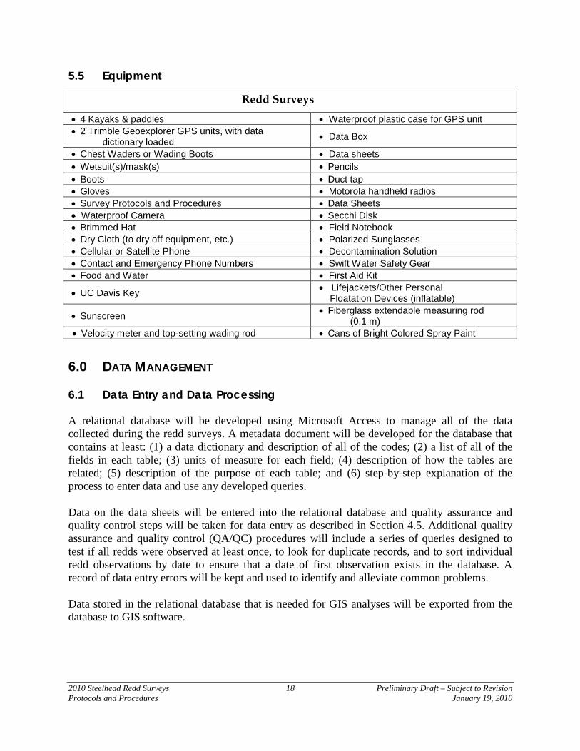
5.5 Equipment
6.0 DATA MANAGEMENT 6.1 Data Entry and Data Processing A relational database will be developed using Microsoft Access to manage all of the data collected during the redd surveys. A metadata document will be developed for the database that contains at least: (1) a data dictionary and description of all of the codes; (2) a list of all of the fields in each table; (3) units of measure for each field; (4) description of how the tables are related; (5) description of the purpose of each table; and (6) step-by-step explanation of the process to enter data and use any developed queries. Data on the data sheets will be entered into the relational database and quality assurance and quality control steps will be taken for data entry as described in Section 4.5. Additional quality assurance and quality control (QA/QC) procedures will include a series of queries designed to test if all redds were observed at least once, to look for duplicate records, and to sort individual redd observations by date to ensure that a date of first observation exists in the database. A record of data entry errors will be kept and used to identify and alleviate common problems. Data stored in the relational database that is needed for GIS analyses will be exported from the database to GIS software.
Redd Surveys
• 4 Kayaks & paddles • Waterproof plastic case for GPS unit • 2 Trimble Geoexplorer GPS units, with data
dictionary loaded • Data Box
• Chest Waders or Wading Boots • Data sheets • Wetsuit(s)/mask(s) • Pencils • Boots • Duct tap • Gloves • Motorola handheld radios • Survey Protocols and Procedures • Data Sheets • Waterproof Camera • Secchi Disk • Brimmed Hat • Field Notebook • Dry Cloth (to dry off equipment, etc.) • Polarized Sunglasses • Cellular or Satellite Phone • Decontamination Solution • Contact and Emergency Phone Numbers • Swift Water Safety Gear • Food and Water • First Aid Kit
• UC Davis Key • Lifejackets/Other Personal Floatation Devices (inflatable)
• Sunscreen • Fiberglass extendable measuring rod (0.1 m)
• Velocity meter and top-setting wading rod • Cans of Bright Colored Spray Paint
2010 Steelhead Redd Surveys 19 Preliminary Draft – Subject to Revision Protocols and Procedures January 19, 2010
6.2 Data Storage and Archival Procedures All original data sheets will be photocopied, well organized, clearly labeled, and archived. Photo copied datasheets will be used for data entry. Reports will be prepared annually and archived. Electronic versions of the data sets, as well as hardcopies of reports, will be submitted to the RMT Planning Group. Raw Data Electronic Storage Format (Software): Microsoft Access Processed Data Electronic Storage Format (Software): Microsoft Excel, Access, ArcMap Electronic files and print copies of the field data sheets will be located at: Yuba County Water Agency Yuba Accord RMT Field Office 1220 F Street 4413 Highway 20 Marysville, CA 95901-4226 Marysville, CA 95901 Data Retrieval Contact: Project Manager – Duane Massa Telephone Number: (530) 570-3474 Email Address: [email protected]
2010 Steelhead Redd Surveys 20 Preliminary Draft – Subject to Revision Protocols and Procedures January 19, 2010
REFERENCES Bovee, K.D. 1978. Probability-of-use criteria for the family Salmonidae. Instream Flow
Information Paper 4, U.S. Fish. Wild. Serv. Buchanan, T.J., and W.P. Somers. 1969. Discharge measurements at gaging stations. Techniques
of water resources investigations of the United States Geological Survey. CALFED and YCWA. 2005. Draft Implementation Plan for Lower Yuba River Anadromous
Fish Habitat Restoration. Prepared on Behalf of the Lower Yuba River Fisheries Technical Working Group by SWRI.
CDFG. 1991. Lower Yuba River Fisheries Management Plan. Stream Evaluation Report No. 91-
1. February 1991. CDFG. 2008. California Department of Fish and Game. Field Gear Decontamination Protocol For New Zealand Mudsnails (Potamopyrgus antipodarum) Draft. CDFG, North Central Region. CDWR. 2003. SP F-10, Task 2B Report 2003 Lower Feather River Steelhead (oncorhynchus
mykiss) redd survey. Oroville facilities relicensing FERC Project No. 2100. Gallagher, S. P., P. J. Hahn, and D. H. Johnson. 2007. Redd Counts. Pages 197-234 in D. H.
Johnson, B. M. Shrier, J. S. O’Neal, J. A. Knutzen, X. Augerot, T. A. O’Neil, and T. N. Pearsons, editors, Salmonid Field Protocols Handbook: Techniques for Assessing Status and Trends in Salmon and Trout Populations. American Fisheries Society, Bethesda MD.
Hannon, J. and B. Deason. 2005. American River Steelhead (Onchorhynchus Mykiss) Spawning
2001 - 2005. Central Valley Project, American River, California Mid-Pacific Region. United States Bureau of Reclamation.
ODFW. 1999. Evaluation of Spawning Ground Surveys for Indexing the Abundance of Adult
Winter Steelhead in Oregon Coastal Basins. http://oregonstate.edu/dept/ODFW/spawn/pdf%20files/reports/steel.pdf Trihey, E.W., and D.L. Wegner. 1981. Field data collection procedures for use with the physical
habitat simulation system of the Instream Flow Service Group. Ft. Collins, CO. USFWS. 2008. Flow-Habitat Relationships for Spring and Fall-run Chinook Salmon and
Steelhead/Rainbow Trout Spawning in the Yuba River. Prepared by personnel of the Energy Planning and Instream Flow Branch. Sacramento, California.