Embed Size (px)
Citation preview
1
CE3166 Tutorial 2: Members under combined axial load and bending moments
Semester 1, AY2009/2010
CE3166 CE Materials and Structural Steel Systems
Tutorial 2:Members under combined axial load
and bending moments
2
CE3166 Tutorial 2: Members under combined axial load and bending moments
Semester 1, AY2009/2010
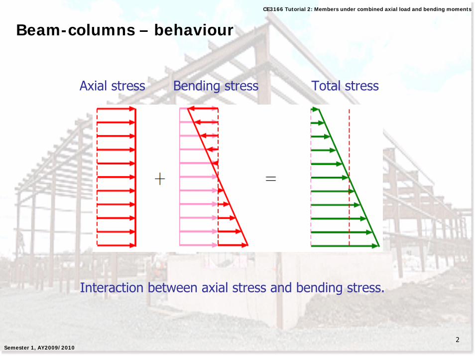
Beam-columns – behaviour
Axial stress Bending stress Total stress
Interaction between axial stress and bending stress.
3
CE3166 Tutorial 2: Members under combined axial load and bending moments
Semester 1, AY2009/2010
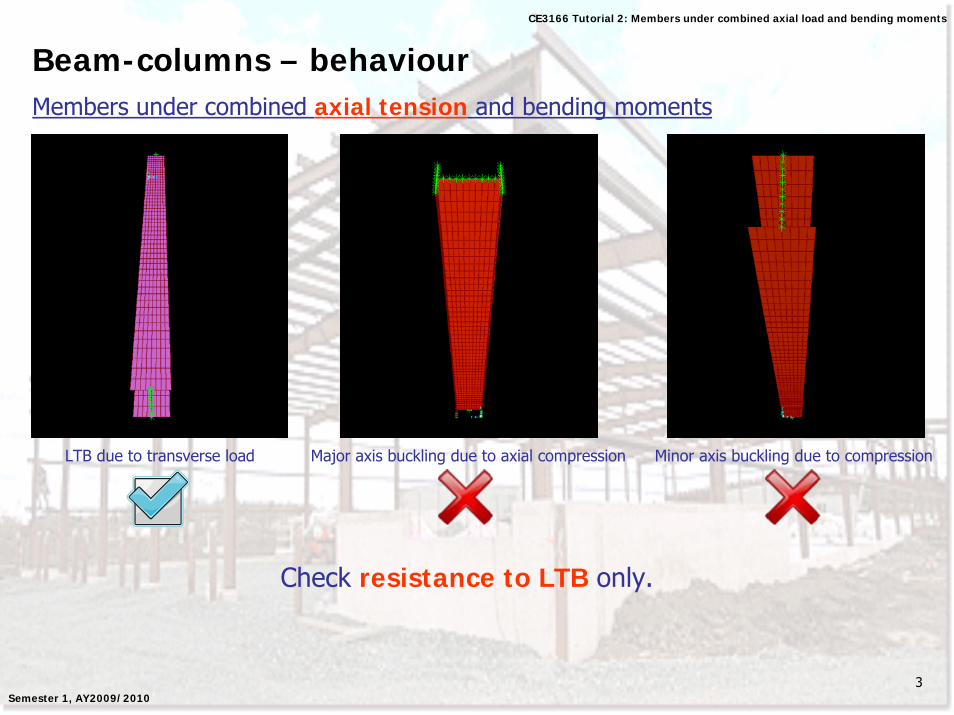
Beam-columns – behaviourMembers under combined axial tension and bending moments
LTB due to transverse load Major axis buckling due to axial compression Minor axis buckling due to compression
Check resistance to LTB only.
4
CE3166 Tutorial 2: Members under combined axial load and bending moments
Semester 1, AY2009/2010
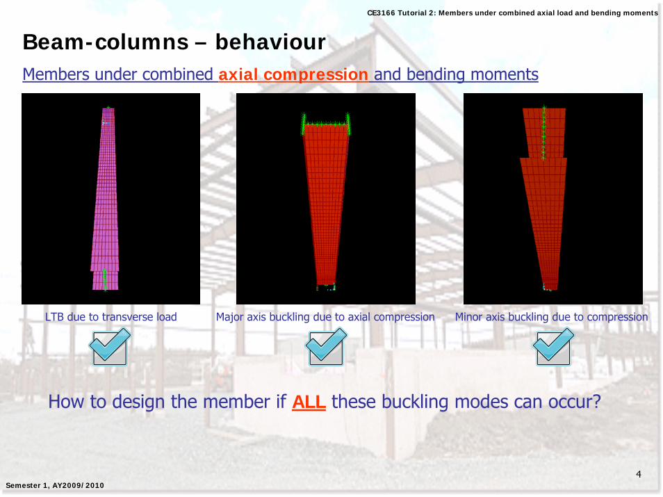
Beam-columns – behaviourMembers under combined axial compression and bending moments
LTB due to transverse load Major axis buckling due to axial compression Minor axis buckling due to compression
How to design the member if ALL these buckling modes can occur?
5
CE3166 Tutorial 2: Members under combined axial load and bending moments
Semester 1, AY2009/2010
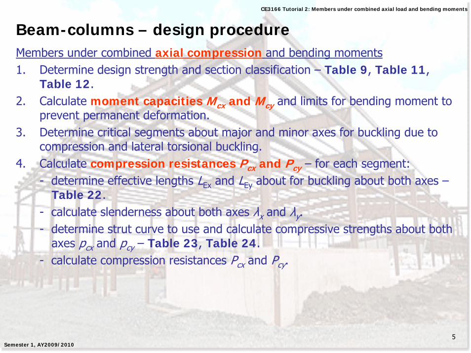
Beam-columns – design procedureMembers under combined axial compression and bending moments1. Determine design strength and section classification – Table 9, Table 11,
Table 12.2. Calculate moment capacities Mcx and Mcy and limits for bending moment to
prevent permanent deformation.3. Determine critical segments about major and minor axes for buckling due to
compression and lateral torsional buckling.4. Calculate compression resistances Pcx and Pcy – for each segment:
- determine effective lengths LEx and LEy about for buckling about both axes –Table 22.
- calculate slenderness about both axes λx and λy.- determine strut curve to use and calculate compressive strengths about both
axes pcx and pcy – Table 23, Table 24.- calculate compression resistances Pcx and Pcy.
6
CE3166 Tutorial 2: Members under combined axial load and bending moments
Semester 1, AY2009/2010
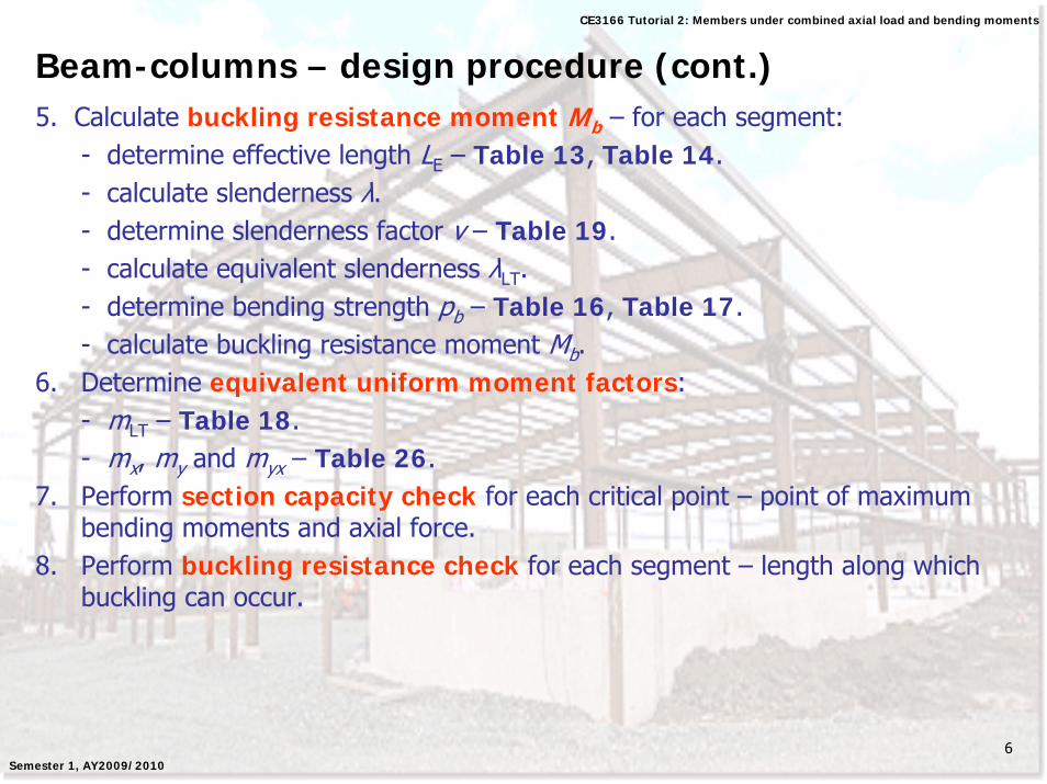
Beam-columns – design procedure (cont.)5. Calculate buckling resistance moment Mb – for each segment:
- determine effective length LE – Table 13, Table 14.- calculate slenderness λ.- determine slenderness factor v – Table 19.- calculate equivalent slenderness λLT.- determine bending strength pb – Table 16, Table 17.- calculate buckling resistance moment Mb.
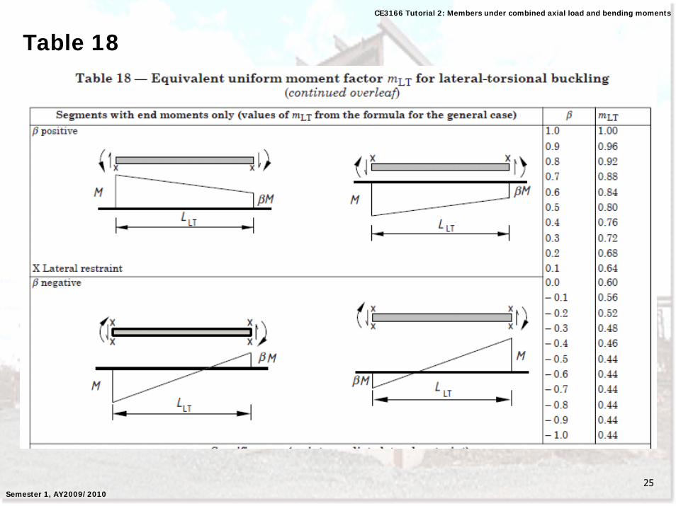
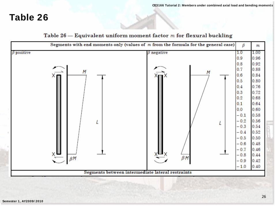
6. Determine equivalent uniform moment factors:- mLT – Table 18.- mx, my and myx – Table 26.
7. Perform section capacity check for each critical point – point of maximum bending moments and axial force.
8. Perform buckling resistance check for each segment – length along which buckling can occur.
7
CE3166 Tutorial 2: Members under combined axial load and bending moments
Semester 1, AY2009/2010
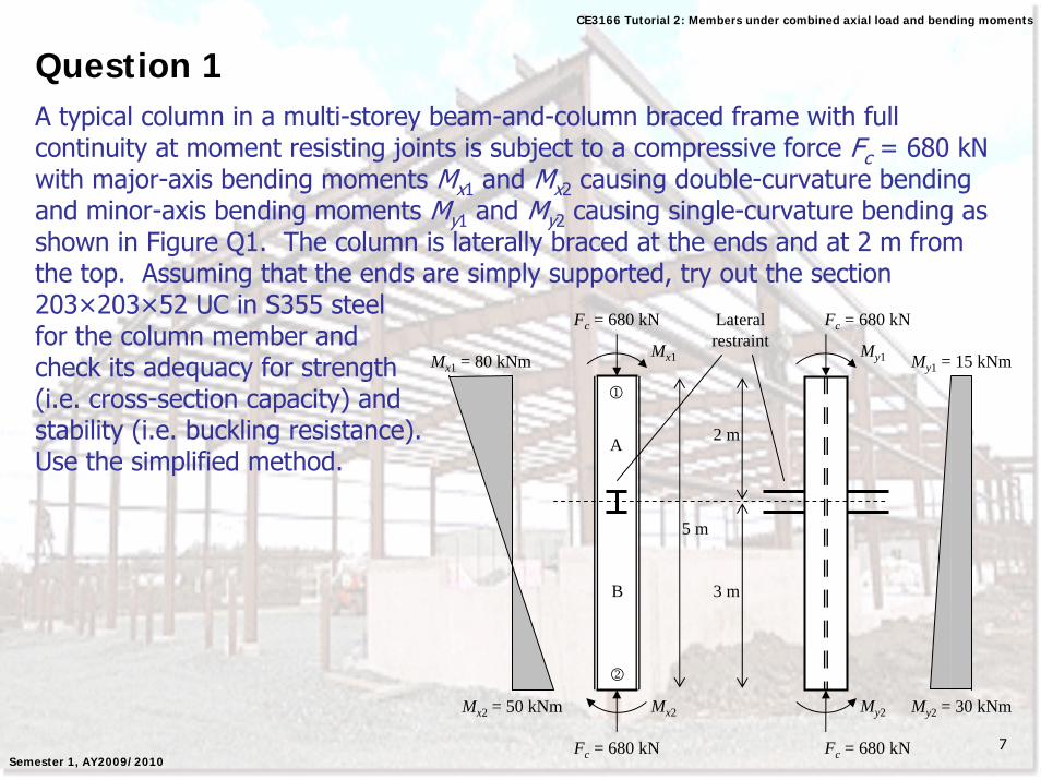
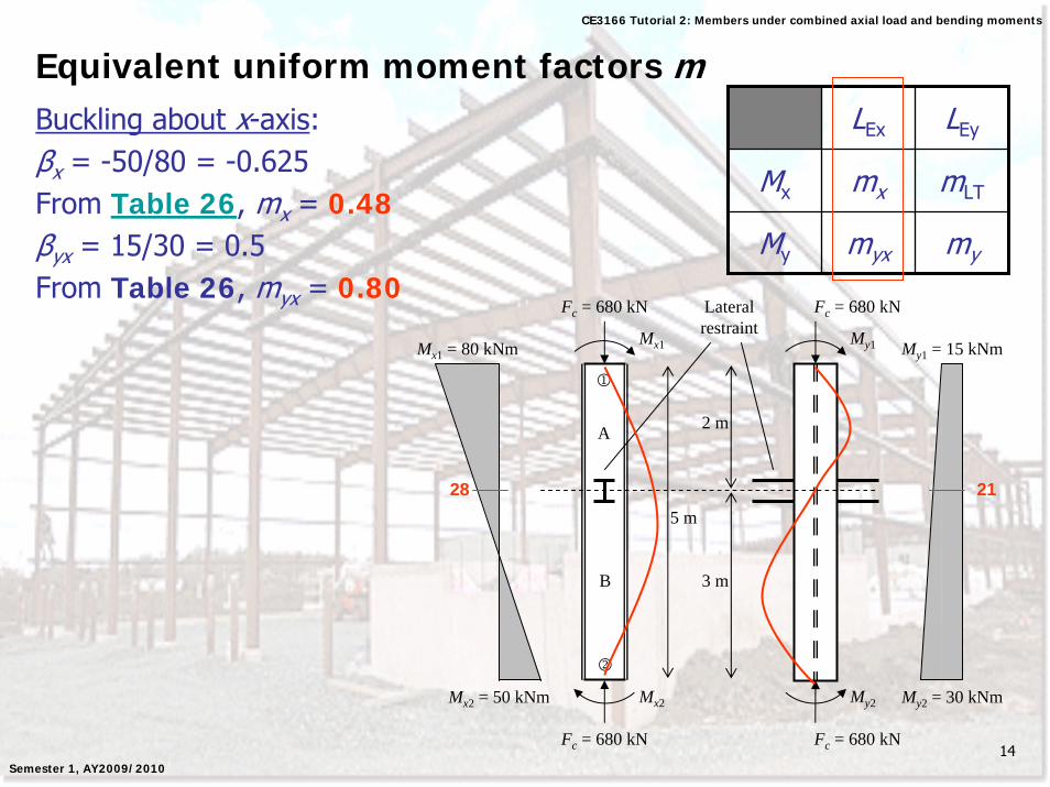
Question 1A typical column in a multi-storey beam-and-column braced frame with full continuity at moment resisting joints is subject to a compressive force Fc = 680 kNwith major-axis bending moments Mx1 and Mx2 causing double-curvature bending and minor-axis bending moments My1 and My2 causing single-curvature bending as shown in Figure Q1. The column is laterally braced at the ends and at 2 m from the top. Assuming that the ends are simply supported, try out the section 203×203×52 UC in S355 steel for the column member and check its adequacy for strength (i.e. cross-section capacity) and stability (i.e. buckling resistance). Use the simplified method.
Fc = 680 kN
5 m
Fc = 680 kN
Mx2 = 50 kNm
Mx1 = 80 kNm Mx1
Mx2
Fc = 680 kN
My1
Fc = 680 kN
My2 My2 = 30 kNm
My1 = 15 kNm
1
2
2 m
3 m
Lateral restraint
A
B
8
CE3166 Tutorial 2: Members under combined axial load and bending moments
Semester 1, AY2009/2010
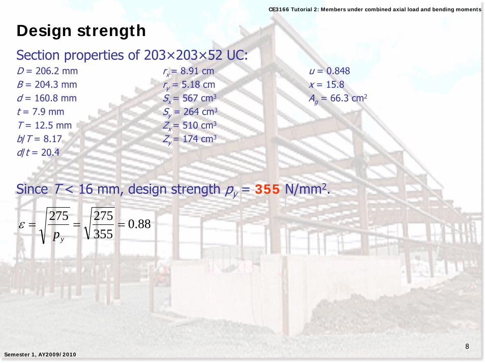
Design strengthSection properties of 203×203×52 UC:D = 206.2 mm rx = 8.91 cm u = 0.848B = 204.3 mm ry = 5.18 cm x = 15.8d = 160.8 mm Sx = 567 cm3 Ag = 66.3 cm2
t = 7.9 mm Sy = 264 cm3
T = 12.5 mm Zx = 510 cm3
b/T = 8.17 Zy = 174 cm3
d/t = 20.4
Since T < 16 mm, design strength py = 355 N/mm2.
88.0355275275
===yp
ε
9
CE3166 Tutorial 2: Members under combined axial load and bending moments
Semester 1, AY2009/2010
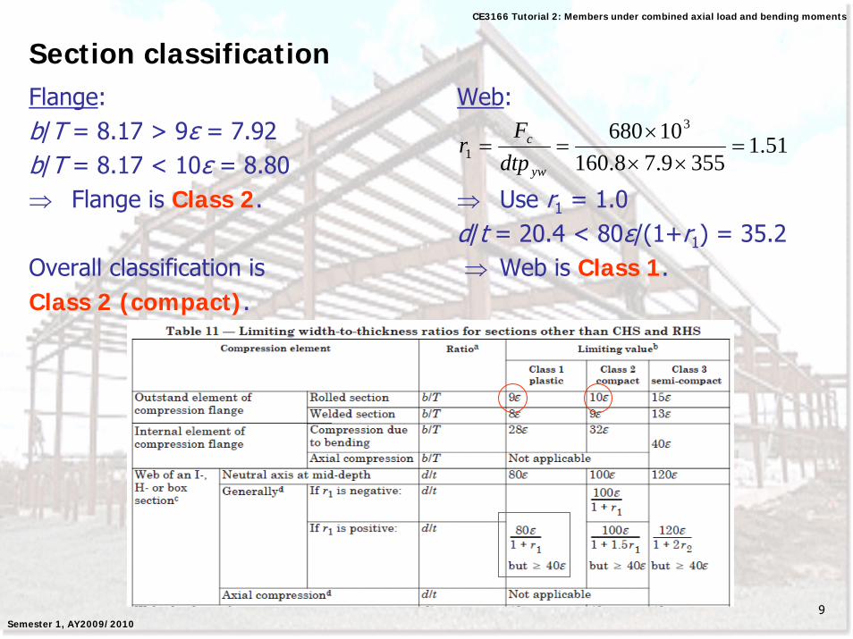
Section classificationFlange: Web:b/T = 8.17 > 9ε = 7.92b/T = 8.17 < 10ε = 8.80⇒ Flange is Class 2. ⇒ Use r1 = 1.0
d/t = 20.4 < 80ε/(1+r1) = 35.2Overall classification is ⇒ Web is Class 1.Class 2 (compact).
51.13559.78.160
10680 3
1 =××
×==
yw
c
dtpF
r
10
CE3166 Tutorial 2: Members under combined axial load and bending moments
Semester 1, AY2009/2010
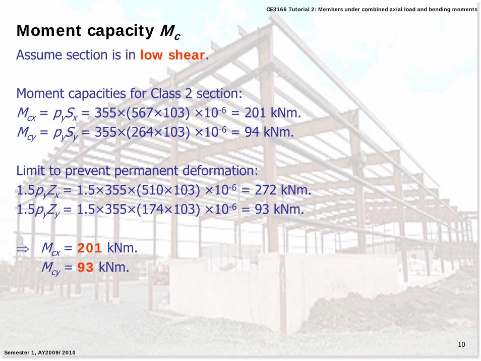
Moment capacity Mc
Assume section is in low shear.
Moment capacities for Class 2 section:Mcx = pySx = 355×(567×103) ×10-6 = 201 kNm.Mcy = pySy = 355×(264×103) ×10-6 = 94 kNm.
Limit to prevent permanent deformation:1.5pyZx = 1.5×355×(510×103) ×10-6 = 272 kNm.1.5pyZy = 1.5×355×(174×103) ×10-6 = 93 kNm.
⇒ Mcx = 201 kNm.Mcy = 93 kNm.
11
CE3166 Tutorial 2: Members under combined axial load and bending moments
Semester 1, AY2009/2010
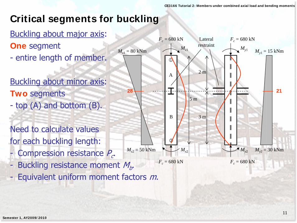
Critical segments for bucklingBuckling about major axis:One segment- entire length of member.
Buckling about minor axis:Two segments- top (A) and bottom (B).
Need to calculate valuesfor each buckling length:- Compression resistance Pc.- Buckling resistance moment Mb.- Equivalent uniform moment factors m.
Fc = 680 kN
5 m
Fc = 680 kN
Mx2 = 50 kNm
Mx1 = 80 kNm Mx1
Mx2
Fc = 680 kN
My1
Fc = 680 kN
My2 My2 = 30 kNm
My1 = 15 kNm
1
2
2 m
3 m
Lateral restraint
A
B
28 21
12
CE3166 Tutorial 2: Members under combined axial load and bending moments
Semester 1, AY2009/2010
Compression resistance Pc
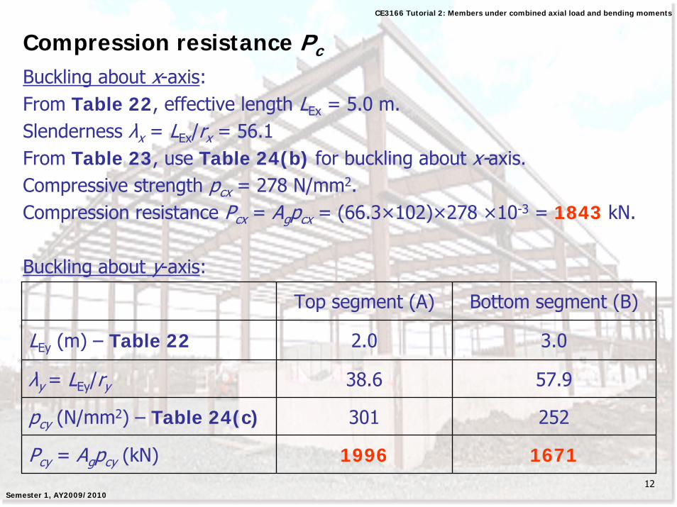
Buckling about x-axis:From Table 22, effective length LEx = 5.0 m.Slenderness λx = LEx/rx = 56.1From Table 23, use Table 24(b) for buckling about x-axis.Compressive strength pcx = 278 N/mm2.Compression resistance Pcx = Agpcx = (66.3×102)×278 ×10-3 = 1843 kN.
Buckling about y-axis:
Top segment (A) Bottom segment (B)
LEy (m) – Table 22 2.0 3.0
λy = LEy/ry 38.6 57.9
pcy (N/mm2) – Table 24(c) 301 252
Pcy = Agpcy (kN) 1996 1671
13
CE3166 Tutorial 2: Members under combined axial load and bending moments
Semester 1, AY2009/2010
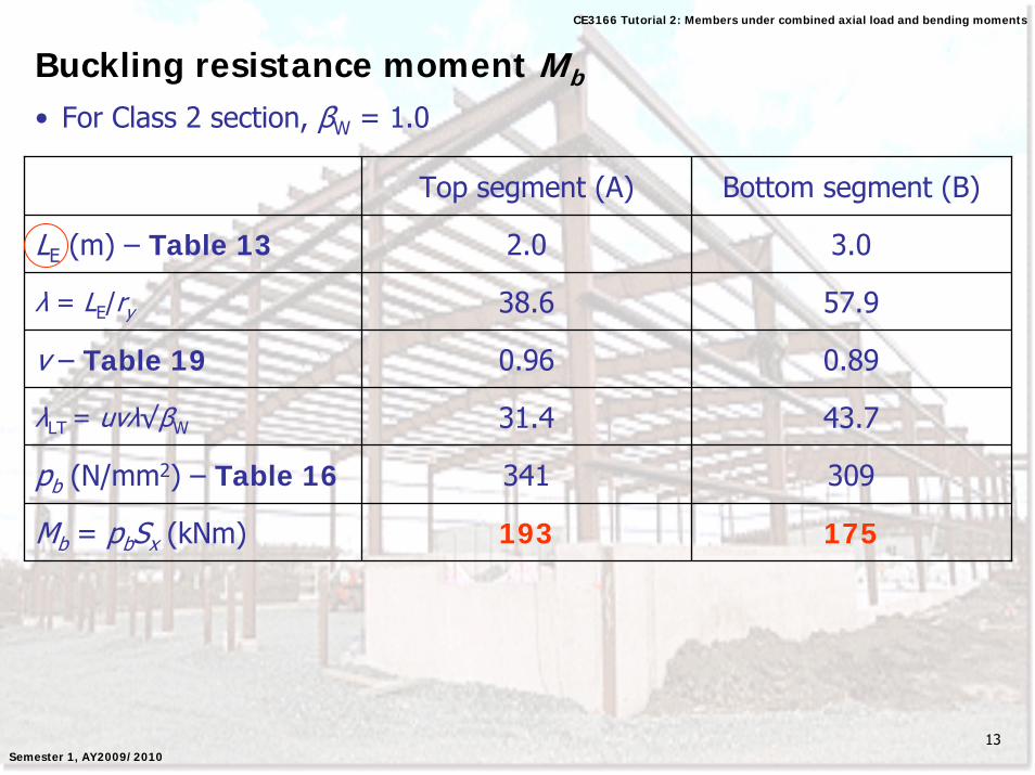
Buckling resistance moment Mb
• For Class 2 section, βW = 1.0
Top segment (A) Bottom segment (B)
LE (m) – Table 13 2.0 3.0
λ = LE/ry 38.6 57.9
v – Table 19 0.96 0.89
λLT = uvλ√βW 31.4 43.7
pb (N/mm2) – Table 16 341 309
Mb = pbSx (kNm) 193 175
14
CE3166 Tutorial 2: Members under combined axial load and bending moments
Semester 1, AY2009/2010
Equivalent uniform moment factors mBuckling about x-axis:βx = -50/80 = -0.625From Table 26, mx = 0.48βyx = 15/30 = 0.5From Table 26, myx = 0.80
Fc = 680 kN
5 m
Fc = 680 kN
Mx2 = 50 kNm
Mx1 = 80 kNm Mx1
Mx2
Fc = 680 kN
My1
Fc = 680 kN
My2 My2 = 30 kNm
My1 = 15 kNm
1
2
2 m
3 m
Lateral restraint
A
B
28 21
LEx LEy
Mx mx mLT
My myx my
15
CE3166 Tutorial 2: Members under combined axial load and bending moments
Semester 1, AY2009/2010
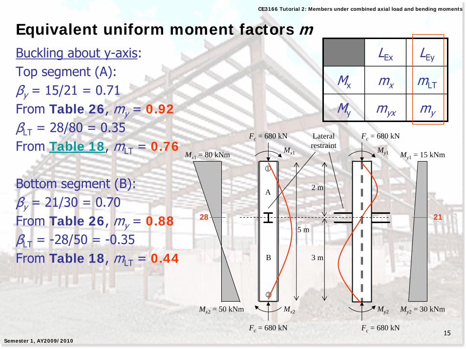
Equivalent uniform moment factors mBuckling about y-axis:Top segment (A):βy = 15/21 = 0.71From Table 26, my = 0.92βLT = 28/80 = 0.35From Table 18, mLT = 0.76
Bottom segment (B):βy = 21/30 = 0.70From Table 26, my = 0.88βLT = -28/50 = -0.35From Table 18, mLT = 0.44
Fc = 680 kN
5 m
Fc = 680 kN
Mx2 = 50 kNm
Mx1 = 80 kNm Mx1
Mx2
Fc = 680 kN
My1
Fc = 680 kN
My2 My2 = 30 kNm
My1 = 15 kNm
1
2
2 m
3 m
Lateral restraint
A
B
28 21
LEx LEy
Mx mx mLT
My myx my
16
CE3166 Tutorial 2: Members under combined axial load and bending moments
Semester 1, AY2009/2010
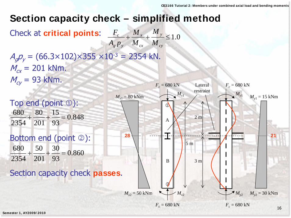
Section capacity check – simplified methodCheck at critical points:
Agpy = (66.3×102)×355 ×10-3 = 2354 kN.Mcx = 201 kNm.Mcy = 93 kNm.
Top end (point 1):
Bottom end (point 2):
Section capacity check passes.
0.1≤++cy
y
cx
x
yg
c
MM
MM
pAF
Fc = 680 kN
5 m
Fc = 680 kN
Mx2 = 50 kNm
Mx1 = 80 kNm Mx1
Mx2
Fc = 680 kN
My1
Fc = 680 kN
My2 My2 = 30 kNm
My1 = 15 kNm
1
2
2 m
3 m
Lateral restraint
A
B
28 21
848.09315
20180
2354680
=++
860.09330
20150
2354680
=++
17
CE3166 Tutorial 2: Members under combined axial load and bending moments
Semester 1, AY2009/2010
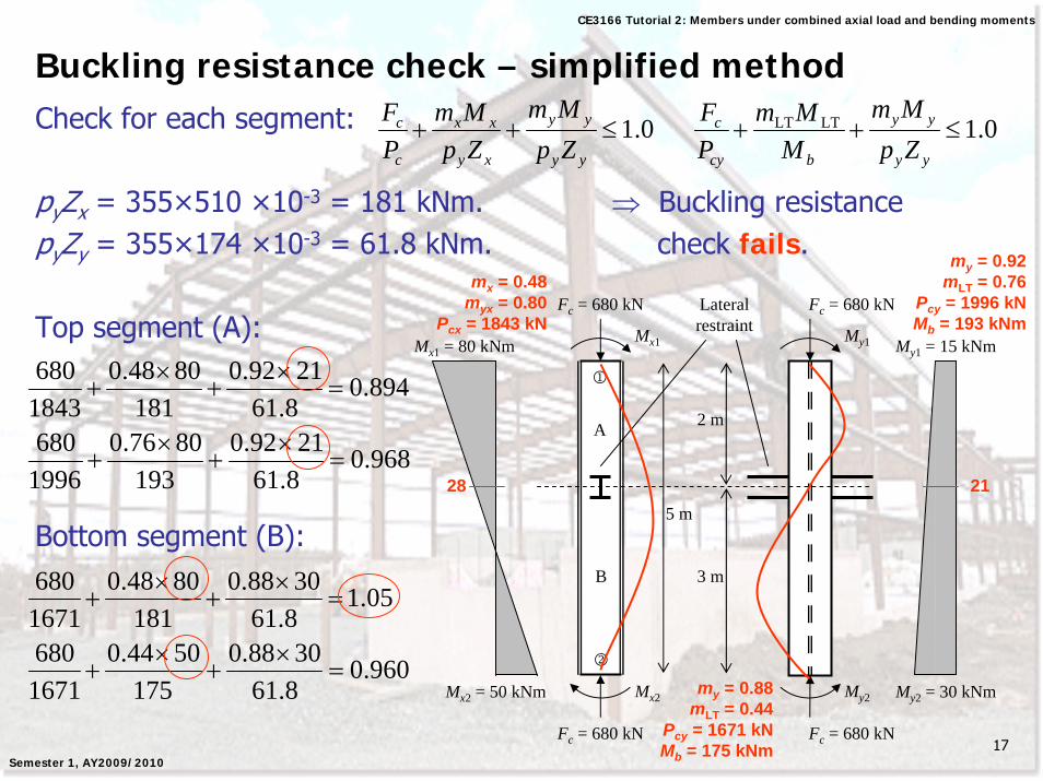
Buckling resistance check – simplified methodCheck for each segment:
pyZx = 355×510 ×10-3 = 181 kNm. ⇒ Buckling resistance pyZy = 355×174 ×10-3 = 61.8 kNm. check fails.
Top segment (A):
Bottom segment (B):
Fc = 680 kN
5 m
Fc = 680 kN
Mx2 = 50 kNm
Mx1 = 80 kNm Mx1
Mx2
Fc = 680 kN
My1
Fc = 680 kN
My2 My2 = 30 kNm
My1 = 15 kNm
1
2
2 m
3 m
Lateral restraint
A
B
28 21
0.1≤++yy
yy
xy
xx
c
c
ZpMm
ZpMm
PF 0.1LTLT ≤++
yy
yy
bcy
c
ZpMm
MMm
PF
894.08.612192.0
1818048.0
1843680
=×
+×
+
mx = 0.48myx = 0.80
Pcx = 1843 kN
my = 0.92mLT = 0.76
Pcy = 1996 kNMb = 193 kNm
my = 0.88mLT = 0.44
Pcy = 1671 kNMb = 175 kNm
968.08.612192.0
1938076.0
1996680
=×
+×
+
05.18.613088.0
1818048.0
1671680
=×
+×
+
960.08.613088.0
1755044.0
1671680
=×
+×
+
18
CE3166 Tutorial 2: Members under combined axial load and bending moments
Semester 1, AY2009/2010
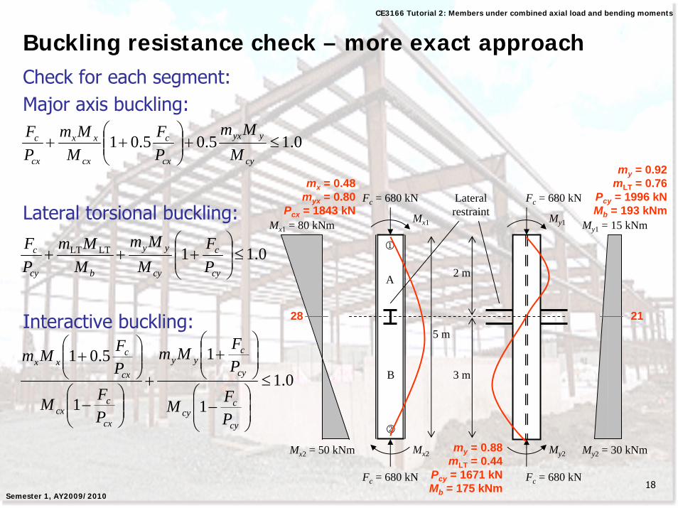
Buckling resistance check – more exact approachCheck for each segment:Major axis buckling:
Lateral torsional buckling:
Interactive buckling:
0.15.05.01 ≤+⎟⎟⎠
⎞⎜⎜⎝
⎛++
cy
yyx
cx
c
cx
xx
cx
c
MMm
PF
MMm
PF
0.11LTLT ≤⎟⎟⎠
⎞⎜⎜⎝
⎛+++
cy
c
cy
yy
bcy
c
PF
MMm
MMm
PF
0.11
1
1
5.01≤
⎟⎟⎠
⎞⎜⎜⎝
⎛−
⎟⎟⎠
⎞⎜⎜⎝
⎛+
+
⎟⎟⎠
⎞⎜⎜⎝
⎛−
⎟⎟⎠
⎞⎜⎜⎝
⎛+
cy
ccy
cy
cyy
cx
ccx
cx
cxx
PFM
PFMm
PFM
PFMm
Fc = 680 kN
5 m
Fc = 680 kN
Mx2 = 50 kNm
Mx1 = 80 kNm Mx1
Mx2
Fc = 680 kN
My1
Fc = 680 kN
My2 My2 = 30 kNm
My1 = 15 kNm
1
2
2 m
3 m
Lateral restraint
A
B
28 21
mx = 0.48myx = 0.80
Pcx = 1843 kN
my = 0.92mLT = 0.76
Pcy = 1996 kNMb = 193 kNm
my = 0.88mLT = 0.44
Pcy = 1671 kNMb = 175 kNm
19
CE3166 Tutorial 2: Members under combined axial load and bending moments
Semester 1, AY2009/2010
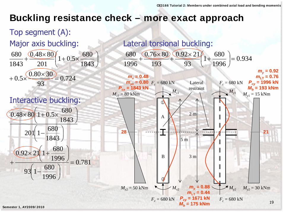
Buckling resistance check – more exact approachTop segment (A):Major axis buckling: Lateral torsional buckling:
Interactive buckling:
934.019966801
932192.0
1938076.0
1996680
=⎟⎠⎞
⎜⎝⎛ +
×+
×+
781.0
1996680193
199668012192.0
18436801201
18436805.018048.0
=⎟⎠⎞
⎜⎝⎛ −
⎟⎠⎞
⎜⎝⎛ +×
+
⎟⎠⎞
⎜⎝⎛ −
⎟⎠⎞
⎜⎝⎛ ×+×
Fc = 680 kN
5 m
Fc = 680 kN
Mx2 = 50 kNm
Mx1 = 80 kNm Mx1
Mx2
Fc = 680 kN
My1
Fc = 680 kN
My2 My2 = 30 kNm
My1 = 15 kNm
1
2
2 m
3 m
Lateral restraint
A
B
28 21
mx = 0.48myx = 0.80
Pcx = 1843 kN
my = 0.92mLT = 0.76
Pcy = 1996 kNMb = 193 kNm
my = 0.88mLT = 0.44
Pcy = 1671 kNMb = 175 kNm
724.093
3080.05.0
18436805.01
2018048.0
1843680
=×
×+
⎟⎠⎞
⎜⎝⎛ ×+
×+
20
CE3166 Tutorial 2: Members under combined axial load and bending moments
Semester 1, AY2009/2010
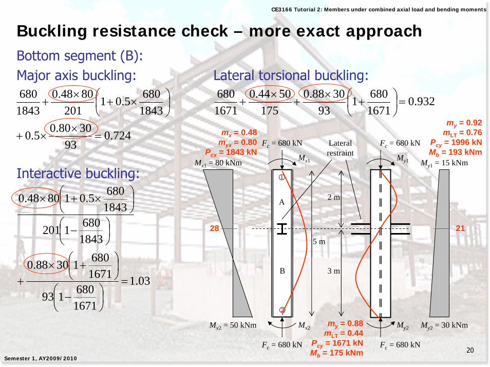
Buckling resistance check – more exact approachBottom segment (B):Major axis buckling: Lateral torsional buckling:
Interactive buckling:
932.016716801
933088.0
1755044.0
1671680
=⎟⎠⎞
⎜⎝⎛ +
×+
×+
03.1
1671680193
167168013088.0
18436801201
18436805.018048.0
=⎟⎠⎞
⎜⎝⎛ −
⎟⎠⎞
⎜⎝⎛ +×
+
⎟⎠⎞
⎜⎝⎛ −
⎟⎠⎞
⎜⎝⎛ ×+×
Fc = 680 kN
5 m
Fc = 680 kN
Mx2 = 50 kNm
Mx1 = 80 kNm Mx1
Mx2
Fc = 680 kN
My1
Fc = 680 kN
My2 My2 = 30 kNm
My1 = 15 kNm
1
2
2 m
3 m
Lateral restraint
A
B
28 21
mx = 0.48myx = 0.80
Pcx = 1843 kN
my = 0.92mLT = 0.76
Pcy = 1996 kNMb = 193 kNm
my = 0.88mLT = 0.44
Pcy = 1671 kNMb = 175 kNm
724.093
3080.05.0
18436805.01
2018048.0
1843680
=×
×+
⎟⎠⎞
⎜⎝⎛ ×+
×+
21
CE3166 Tutorial 2: Members under combined axial load and bending moments
Semester 1, AY2009/2010
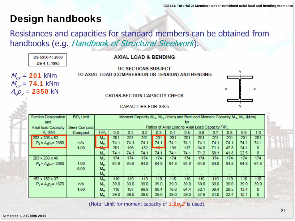
Design handbooksResistances and capacities for standard members can be obtained from handbooks (e.g. Handbook of Structural Steelwork).
Mcx = 201 kNmMcy = 74.1 kNmAgpy = 2350 kN
(Note: Limit for moment capacity of 1.2pyZ is used).
22
CE3166 Tutorial 2: Members under combined axial load and bending moments
Semester 1, AY2009/2010
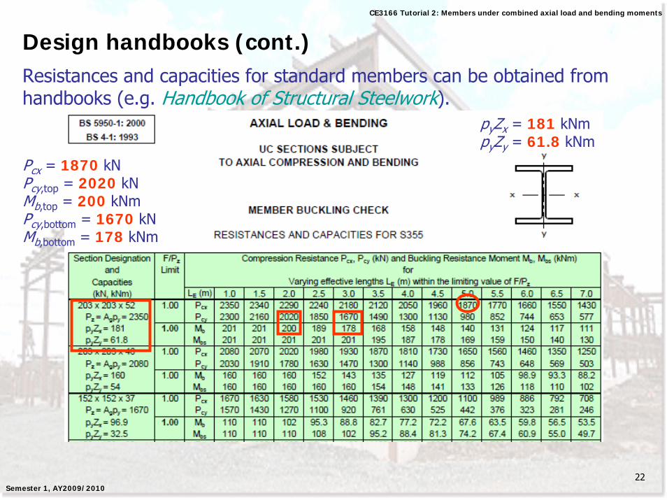
Design handbooks (cont.)Resistances and capacities for standard members can be obtained from handbooks (e.g. Handbook of Structural Steelwork).
Pcx = 1870 kNPcy,top = 2020 kNMb,top = 200 kNmPcy,bottom = 1670 kNMb,bottom = 178 kNm
pyZx = 181 kNmpyZy = 61.8 kNm
23
CE3166 Tutorial 2: Members under combined axial load and bending moments
Semester 1, AY2009/2010
Questions to ponder1. What if shear in member is high? How would you account for high
shear in the section capacity and buckling resistance checks?
2. Since it is possible for a member to pass the buckling resistance check using the simplified method but FAIL the same check using the more exact method, is it necessary to perform the more exact check even if the simplified check passes?
3. Suppose you have two members of the same section which are subjected to the same axial force, bending moment distribution, support and restraint conditions. However, these members are ofdifferent lengths. If the shorter member passes the section capacity check, will the longer member also pass the same check?
24
CE3166 Tutorial 2: Members under combined axial load and bending moments
Semester 1, AY2009/2010
Questions to ponder4. Should you use the algebraic or absolute values for moments Mx
and My to determine the equivalent uniform moment factors mx, my,mLT and myx? How about for the section capacity and buckling resistance checks?
25
CE3166 Tutorial 2: Members under combined axial load and bending moments
Semester 1, AY2009/2010
Table 18
26
CE3166 Tutorial 2: Members under combined axial load and bending moments
Semester 1, AY2009/2010
Table 26


![Sintap British Steel Bs-23[1]](https://img.pdfslide.us/doc/110x75/577d348e1a28ab3a6b8e4dd6/sintap-british-steel-bs-231.jpg)