Embed Size (px)
Citation preview

A N A M E R I C A N N A T I O N A L S T A N D A R D
Steel Stacks
ASME STS-1–2006(Revision of ASME STS-1–2000)
Copyright ASME International Provided by IHS under license with ASME
Not for ResaleNo reproduction or networking permitted without license from IHS
--`,,```,,,,````-`-`,,`,,`,`,,`---
//^:^
^#^~
^^""
~:@
":^*^
~$~"
#:*~
:*@
^:#^
#:~~
^^~:
^":^
@::~
*\\
ASME STS-1–2006(Revision of ASME STS-1–2000)
Steel Stacks
A N A M E R I C A N N A T I O N A L S T A N D A R D
Three Park Avenue • New York, NY 10016
Copyright ASME International Provided by IHS under license with ASME
Not for ResaleNo reproduction or networking permitted without license from IHS
--`,,```,,,,````-`-`,,`,,`,`,,`---
//^:^^#^~^^""~:@":^*^~$~"#:*~:*@
^:#^#:~~^^~:^":^@::~*\\
Date of Issuance: October 13, 2006
The 2006 edition of this Standard is being issued with an automatic addenda subscription service.The use of addenda allows revisions made in response to public review comments or committeeactions to be published as necessary. This Standard will be revised when the Society approves theissuance of a new edition.
ASME issues written replies to inquiries concerning interpretations of technical aspects of thisStandard. The interpretations will be included with the above addenda service.
ASME is the registered trademark of The American Society of Mechanical Engineers.
This code or standard was developed under procedures accredited as meeting the criteria for American NationalStandards. The Standards Committee that approved the code or standard was balanced to assure that individuals fromcompetent and concerned interests have had an opportunity to participate. The proposed code or standard was madeavailable for public review and comment that provides an opportunity for additional public input from industry, academia,regulatory agencies, and the public-at-large.
ASME does not “approve,” “rate,” or “endorse” any item, construction, proprietary device, or activity.ASME does not take any position with respect to the validity of any patent rights asserted in connection with any
items mentioned in this document, and does not undertake to insure anyone utilizing a standard against liability forinfringement of any applicable letters patent, nor assumes any such liability. Users of a code or standard are expresslyadvised that determination of the validity of any such patent rights, and the risk of infringement of such rights, isentirely their own responsibility.
Participation by federal agency representative(s) or person(s) affiliated with industry is not to be interpreted asgovernment or industry endorsement of this code or standard.
ASME accepts responsibility for only those interpretations of this document issued in accordance with the establishedASME procedures and policies, which precludes the issuance of interpretations by individuals.
No part of this document may be reproduced in any form,in an electronic retrieval system or otherwise,
without the prior written permission of the publisher.
The American Society of Mechanical EngineersThree Park Avenue, New York, NY 10016-5990
Copyright © 2006 byTHE AMERICAN SOCIETY OF MECHANICAL ENGINEERS
All Rights ReservedPrinted in U.S.A.
Copyright ASME International Provided by IHS under license with ASME
Not for ResaleNo reproduction or networking permitted without license from IHS
--`,,```,,,,````-`-`,,`,,`,`,,`---
//^:^
^#^~
^^""
~:@
":^*^
~$~"
#:*~
:*@
^:#^
#:~~
^^~:
^":^
@::~
*\\

iii
CONTENTS
Foreword . . . . . . . . . . . . . . . . . . . . . . . . . . . . . . . . . . . . . . . . . . . . . . . . . . . . . . . . . . . . . . . . . . . . . . . . . . . . . . ivCommittee Roster . . . . . . . . . . . . . . . . . . . . . . . . . . . . . . . . . . . . . . . . . . . . . . . . . . . . . . . . . . . . . . . . . . . . . vCorrespondence with the Steel Stacks Committee . . . . . . . . . . . . . . . . . . . . . . . . . . . . . . . . . . . . . . . viIntroduction . . . . . . . . . . . . . . . . . . . . . . . . . . . . . . . . . . . . . . . . . . . . . . . . . . . . . . . . . . . . . . . . . . . . . . . . . . . vii
1 Mechanical Design . . . . . . . . . . . . . . . . . . . . . . . . . . . . . . . . . . . . . . . . . . . . . . . . . . . . . . . . . . . 1
2 Materials . . . . . . . . . . . . . . . . . . . . . . . . . . . . . . . . . . . . . . . . . . . . . . . . . . . . . . . . . . . . . . . . . . . . 4
3 Linings and Coatings . . . . . . . . . . . . . . . . . . . . . . . . . . . . . . . . . . . . . . . . . . . . . . . . . . . . . . . . 7
4 Structural Design . . . . . . . . . . . . . . . . . . . . . . . . . . . . . . . . . . . . . . . . . . . . . . . . . . . . . . . . . . . . 13
5 Dynamic Wind Loads . . . . . . . . . . . . . . . . . . . . . . . . . . . . . . . . . . . . . . . . . . . . . . . . . . . . . . . . . 20
6 Access and Safety . . . . . . . . . . . . . . . . . . . . . . . . . . . . . . . . . . . . . . . . . . . . . . . . . . . . . . . . . . . 23
7 Electrical . . . . . . . . . . . . . . . . . . . . . . . . . . . . . . . . . . . . . . . . . . . . . . . . . . . . . . . . . . . . . . . . . . . . 28
8 Fabrication and Erection . . . . . . . . . . . . . . . . . . . . . . . . . . . . . . . . . . . . . . . . . . . . . . . . . . . . . . 29
9 Inspection and Maintenance . . . . . . . . . . . . . . . . . . . . . . . . . . . . . . . . . . . . . . . . . . . . . . . . . . 31
10 References . . . . . . . . . . . . . . . . . . . . . . . . . . . . . . . . . . . . . . . . . . . . . . . . . . . . . . . . . . . . . . . . . . 33
Figures6.2.6-1 Example of the General Construction of Cages . . . . . . . . . . . . . . . . . . . . . . . . . . . . . . . 246.2.6-2 Minimum Ladder Clearances . . . . . . . . . . . . . . . . . . . . . . . . . . . . . . . . . . . . . . . . . . . . . . . . 256.3.6 Ladder Dimensions, Support Spacing, and Side Clearances . . . . . . . . . . . . . . . . . . . 266.3.8 Landing Platform Dimensions . . . . . . . . . . . . . . . . . . . . . . . . . . . . . . . . . . . . . . . . . . . . . . . 27
Tables4.4.6 Factors of Safety . . . . . . . . . . . . . . . . . . . . . . . . . . . . . . . . . . . . . . . . . . . . . . . . . . . . . . . . . . . . 164.4.7 Minimum Structural Plate Thickness and Maximum Stiffener Spacing . . . . . . . . 164.10.1.3 Cable Selection Criteria . . . . . . . . . . . . . . . . . . . . . . . . . . . . . . . . . . . . . . . . . . . . . . . . . . . . . 185.2.1 Representative Structural Damping Values (�s) . . . . . . . . . . . . . . . . . . . . . . . . . . . . . . . 21
Mandatory AppendixI Structural Design . . . . . . . . . . . . . . . . . . . . . . . . . . . . . . . . . . . . . . . . . . . . . . . . . . . . . . . . . . . 35
Nonmandatory AppendicesA Mechanical Design . . . . . . . . . . . . . . . . . . . . . . . . . . . . . . . . . . . . . . . . . . . . . . . . . . . . . . . . . . 46B Materials for Ambient and Elevated Temperature Service . . . . . . . . . . . . . . . . . . . . . 59C Linings and Coatings . . . . . . . . . . . . . . . . . . . . . . . . . . . . . . . . . . . . . . . . . . . . . . . . . . . . . . . 75D Structural Design . . . . . . . . . . . . . . . . . . . . . . . . . . . . . . . . . . . . . . . . . . . . . . . . . . . . . . . . . . . 79E Example Calculations . . . . . . . . . . . . . . . . . . . . . . . . . . . . . . . . . . . . . . . . . . . . . . . . . . . . . . . 86F Conversion Factors: U.S. Customary to SI (Metric) . . . . . . . . . . . . . . . . . . . . . . . . . . . 97
Copyright ASME International Provided by IHS under license with ASME
Not for ResaleNo reproduction or networking permitted without license from IHS
--`,,```,,,,````-`-`,,`,,`,`,,`---
//^:^^#^~^^""~:@":^*^~$~"#:*~:*@^:#^#:~~^^~:^":^@::~*\\
FOREWORD
In early 1978, the American Society of Mechanical Engineers was approached by a groupinterested in formulating a standard for the design, fabrication, and erection of steel stacks andtheir appurtenances. They felt there was a need for such a code to establish a better level ofstandardization in the industry and for safeguarding the community. Because of the particularnature of stacks and their susceptibility to failures due to wind and seismic-induced vibrations,along with corrosion and erosion, the design process is a complex one. Additionally, recentregulations by the Environmental Protection Agency concerning emissions have placed a strongemphasis on the mechanical design of stacks. In the last several decades, much research has beendone and many papers written on the subject. While investigation and research continued, itwas the feeling of these persons that some formal guidelines needed to be established. Therefore,in April of 1979, a group comprised of stack users, researchers, designers, fabricators, and erectorsconvened at the United Engineering Center in New York City under the auspices of the AmericanSociety of Mechanical Engineers to formulate such a code.
With the above in mind, the group subdivided and began gathering information to formulateguidelines for mechanical design, material selection, the use of linings and coatings, structuraldesign, vibration considerations, access and safety, electrical requirements, and fabrication andconstruction. When these were established, a section on maintenance and inspection was added.The following is a result of their work and investigation. The initial document was approved asan American National Standard in August 1986 and published as ASME/ANSI STS-1-1986 inMay 1988.
During the next three years, the committee received comments from the public at large andfrom its own membership regarding the Standard’s content. Several formulas needed correctionand some of the symbols needed clarification. Section 6.3.3 regarding Earthquake Response wasalso reviewed and revised to allow for static rather than dynamic analysis in certain cases, andto correlate it with ASCE STD-7-88 (formerly ANSI A58-1). These changes were then submittedto the general membership and approved.
In 1994, the committee was reorganized to further review and update this steel stack Standard.Emphasis was given to the Structural Design and Vibrations chapters. Chapter 4, “StructuralDesign,” was rewritten to be more compatible with the nomenclature, formulae, and symbolsused in the Manual of Steel Construction - Allowable Stress Design (ASD), 9th Edition and Loadand Resistance Factor Design (LRFD) 1st Edition. Chapter 5, “Vibrations,” was revised to bemore “user friendly.” These and other chapters were updated to include the latest recognizedapplicable codes and standards.
This edition includes changes and improvements to the Environmental Protection Agencyregulation concerning emissions that have created a strong emphasis on the mechanical designof steel stacks, makes necessary changes found through practical experience with the previousedition, expands formulas as necessary, and provides both revised and new sections for steelstack design, fabrication, and erection. It revises sections on appurtenances to meet today’srequirements for these items. A new section provides the fundamental concepts for guyed stacks.Revisions to the section on the physical properties of steel at elevated temperatures have beenmade to match information available through a comprehensive review of current technical litera-ture. Sections on vibration include minor changes but will yield a more workable standard. Also,a detailed example is included to provide a method for determining the magnitude of acrosswind loads. One method is included to address fatigue due to vibration. Fatigue can be a significantissue in steel stack design and needs to be considered in the design. Methods to determine acrosswind load and seismic loads are provided in the nonmandatory appendices. If fatigue requiresclose examination, the engineer is cautioned to review this issue with other design standards ifnecessary. There are several standards among them: AISC, CICIND, or ASME that can be helpful.
This revised standard was approved as an American National Standard on March 21, 2006and reissued as STS-1-2006.
iv
Copyright ASME International Provided by IHS under license with ASME
Not for ResaleNo reproduction or networking permitted without license from IHS
--`,,```,,,,````-`-`,,`,,`,`,,`---
//^:^
^#^~
^^""
~:@
":^*^
~$~"
#:*~
:*@
^:#^
#:~~
^^~:
^":^
@::~
*\\

ASME STS COMMITTEESteel Stacks
(The following is the roster of the Committee at the time of approval of this Standard.)
OFFICERS
J. C. Sowizal, ChairM. J. Gault, Vice Chair
A. L. Guzman, Secretary
COMMITTEE PERSONNEL
A. K. Bhowmik, Hamon CustodisK. Scott, Alternate, Hamon CustodisJ. J. Carty, R and P Industrial Chimney Co.V. Z. Gandelsman, ConsultantM. J. Gault, Braden ManufacturingA. L. Guzman, The American Society of Mechanical EngineersW. L. Mathay, Nickel Development InstituteD. C. Mattes, Hoffmann, Inc.T. Oswald, Jr., Sauereisen Co.S. L. Reid, Industrial Environment Systems, Inc.C. Reid, Alternate, Industrial Environment Systems, Inc.W. C. Rosencutter, Meca Enterprises, Inc.R. K. Simonetti, Parsons E&CR. L. Schneider, Alternate, Parsons E&CR. S. Slay, Warren Environment, Inc.J. C. Sowizal, Industrial Chimney Engineering Co.B. J. Vickery, University of Western OntarioL. A. Yadav, Foster Wheeler Energy Corp.W. J. Van Dyke, Alternate, Foster Wheeler Energy Corp.N. Zarrabi, Assoc. Engineering Resources, Inc.
v
Copyright ASME International Provided by IHS under license with ASME
Not for ResaleNo reproduction or networking permitted without license from IHS
--`,,```,,,,````-`-`,,`,,`,`,,`---
//^:^^#^~^^""~:@":^*^~$~"#:*~:*@
^:#^#:~~^^~:^":^@::~*\\

CORRESPONDENCE WITH THE STEEL STACKSCOMMITTEE
General. ASME Standards are developed and maintained with the intent to represent theconsensus of concerned interests. As such, users of this Standard may interact with the Committeeby requesting interpretations, proposing revisions, and attending Committee meetings. Corre-spondence should be addressed to:
Secretary, Steel Stacks Standards CommitteeThe American Society of Mechanical EngineersThree Park AvenueNew York, NY 10016
Proposing Revisions. Revisions are made periodically to the Steel Stacks Standard to incorporatechanges that appear necessary or desirable, as demonstrated by the experience gained from theapplication of the Standard. Approved revisions will be published periodically.
The Committee welcomes proposals for revisions to this Standard. Such proposals should beas specific as possible, citing the paragraph number(s), the proposed wording, and a detaileddescription of the reasons for the proposals, including any pertinent documentation.
Interpretations. Upon request, the Committee will render an interpretation of any requirementof the Standard. Interpretations can only be rendered in response to a written request sent to theSecretary of the Steel Stacks Standards Committee.
The request for interpretation should be clear and unambiguous. It is further recommendedthat the inquirer submit his request in the following format:
Subject: Cite the applicable paragraph number(s) and concise description.Edition: Cite the applicable edition of the Standard for which the interpretation is
being requested.Question: Phrase the question as a request for an interpretation of a specific requirement
suitable for general understanding and use, not as a request for an approvalof a proprietary design or situation. The inquirer may also include any plansor drawings, which are necessary to explain the question; however, theyshould not contain proprietary names or information.
Requests that are not in this format will be rewritten in this format by the Committee priorto being answered, which may inadvertently change the intent of the original request.
ASME procedures provide for reconsideration of any interpretation when or if additionalinformation that might affect an interpretation is available. Further, persons aggrieved by aninterpretation may appeal to the cognizant ASME Committee or Subcommittee. ASME does not“approve,” “certify,” “rate,” or “endorse” any item, construction, proprietary device, or activity.
Attending Committee Meetings. The Steel Stacks Standards Committee regularly holds meet-ings, which are open to the public. Persons wishing to attend any meeting should contact theSecretary of the Steel Stacks Standards Committee.
vi
Copyright ASME International Provided by IHS under license with ASME
Not for ResaleNo reproduction or networking permitted without license from IHS
--`,,```,,,,````-`-`,,`,,`,`,,`---
//^:^
^#^~
^^""
~:@
":^*^
~$~"
#:*~
:*@
^:#^
#:~~
^^~:
^":^
@::~
*\\

INTRODUCTION
The following Standard applies to steel stacks; that is, those stacks where the primary supportingshell is made of steel. It applies to both single- and multiple-walled steel stacks, either of whichcan be lined or unlined. It also applies to steel stacks that are guyed, or to certain aspects oftower stacks. The stack may be supported on a foundation or from another structure.
This Standard covers many facets of the design of steel stacks. It outlines the considerationwhich must be made for both the mechanical and structural design. It emphasizes what consider-ation must be taken for wind- and seismic-induced vibrations. It gives guidelines for the selectionof material, linings, and coatings. It gives the requirements for lighting and lightning protectionbased upon existing building and federal codes. It gives the requirements for climbing andaccess based upon current Occupational Safety and Health Administration (OSHA) standards. Itemphasizes the important areas regarding fabrication and construction. It outlines areas requiringmaintenance and inspection following initial operation.
Although many of the topics within these guidelines may be used for all stacks, this Standardis intended to provide design guidelines for stacks containing nonflammable gases such ascombustion exhaust gases at low internal pressures. For stacks containing combustible gasesunder pressure such as flare stacks and flammable vents, additional design considerations mustbe addressed, including design for internal pressure, design for internal deflagration pressure,and compatibility with adjoining piping design that is in accordance with piping and/or vesseldesign codes such as ASME B31.3 and Section VIII of the ASME Boiler and Pressure Vessel Code(BPVC). In addition, the materials of construction referenced in this Standard may not be allowedfor use with flammable gases under pressure per ASME B31.3 and Section VIII of the ASMEBPVC; materials suitable for pressure containment of flammable gases are listed in these codes.No attempt is made within this Standard to define the need or the methods to be used to considerthese additional design considerations.
The information presented has been prepared in accordance with established engineeringprinciples utilizing state-of-the-art information. It is intended for general information. Whileevery effort has been made to ensure its accuracy, the information should not be relied upon forany specific application without the consultation of a competent, licensed professional engineerto determine its suitability. It is therefore recommended that Engineering/Design drawings ofthe stack bear the Professional Engineer Seal, signature, and date.
Nothing in the Standard shall be construed to alter or subvert the requirements of any existingcode or authority having jurisdiction over the facility. Furthermore, alternate methods and materi-als to those herein indicated may be used, provided that the engineer can demonstrate theirsuitability to all affected agencies and authorities.
vii
Copyright ASME International Provided by IHS under license with ASME
Not for ResaleNo reproduction or networking permitted without license from IHS
--`,,```,,,,````-`-`,,`,,`,`,,`---
//^:^^#^~^^""~:@":^*^~$~"#:*~:*@^:#^#:~~^^~:^":^@::~*\\

viii
Copyright ASME International Provided by IHS under license with ASME
Not for ResaleNo reproduction or networking permitted without license from IHS
--`,,```,,,,````-`-`,,`,,`,`,,`---
//^:^^#^~^^""~:@":^*^~$~"#:*~:*@^:#^#:~~^^~:^":^@::~*\\

ASME STS-1–2006
STEEL STACKS
1 MECHANICAL DESIGN
1.1 Scope
Mechanical design includes sizing of the gas passage,both in diameter and height; and the drop in gas temper-ature as heat is transferred through the stack wall. Meth-ods for calculating draft, draft losses, and heat lossesare given. Differential expansion of stack componentsis discussed. Design considerations for stack appurte-nances are established.
1.2 General
The purpose of a stack is to vent process exhaust gasesto the atmosphere. The mechanical design of stacks isnow controlled in part by air pollution rules and regula-tions. Heights and diameters are set by a balancebetween structural stability and function, while at thesame time meeting the requirements for air pollutioncontrol dispersion of the gases to the atmosphere. Theheights of steel stacks have increased to satisfy ambientair quality, and stack inlet gas temperatures havedecreased as more heat energy is recovered. The impor-tance of attention to stack heat losses has thereforeincreased. Stack minimum metal temperature should beheld above the acid dew point of the vented gases, ifpossible. Stacks are being designed with many appurte-nances to monitor the gases and make stack inspections.
1.3 Size Selection (Height, Diameter, and Shape)
1.3.1 Height. Stack height may be set by one or morefactors.
(a) Environmental Protection Agency (EPA) regula-tions may set the required stack height for downwashdue to local terrain or adjacent structures, or to dispersepollutants at a minimum height above the site. Referproposed stack location and purposes to the proper EPAauthorities for the minimum height requirement undercontrolling air pollution control regulations. See Federalregister part II EPA 40CFR, part 51, Stack Height Regula-tion (July 8, 1985).
(b) The National Fire Protection Association (NFPA)sets minimum height of high-temperature stacks abovebuilding roofs and structures for fire protection andhuman safety. Local codes are often more stringent andmust be followed. A minimum of 8 ft of height abovea roof surface or roof mounted structure within 25 ft ofa stack emitting gases above 200°F (93°C) should bemaintained.
1
(c) The draft requirement of the process to be ventedmay establish stack height. Formulas to calculate avail-able draft are presented in subsequent paragraphs.
(d) The effective height of a stack considering plumerise may be increased by installing a nozzle or truncatedcone at the top to increase the exit velocity of the gases.Several plume rise formulas are available but in actualpractice, plume rise can be essentially negated by highwind velocities, low temperatures, and site conditions.
1.3.2 Diameters. The stack diameter may be set byone or more factors.
(a) Gas passage diameter is usually established bythe volume of process gas flowing and available draft(natural draft minus draft losses). Velocities in a roundstack between 2400 and 3600 ft/min are most common.Stacks venting saturated gases sometimes limit maxi-mum stack velocities between 1800 and 2400 ft/min toreduce entrained or condensed moisture from leavingthe stack exit. Tests by EPRI give different ranges foreach type of inner surface (see EPRI Wet Stack DesignGuide TR-107099-1996).
(b) Stack shell diameters may be controlled by trans-portation shipping limitations. Caution should be takento ensure that mechanical performance and structuralstability are maintained.
(c) Structural stability may control a stack shell diam-eter selection and therefore, any size selection based onmechanical criteria must be maintained as tentative untila structural analysis can confirm its acceptability.
(d) Future increases in stack gas volume should beconsidered as well as future changes in process gas tem-peratures and gas quality in the diameter selection.
(e) EPA regulations may set stack exit diameterbecause of plume rise considerations. EPA requirementshave sometimes set stack diameters in the test zone toprovide optimum velocities for testing.
1.3.3 Shape. The shape of the stack varies withdesigners’ preferences.
(a) Stacks generally are cylindrical in shape for effi-ciency in structural stability and economy in fabrication.Cylindrical shapes may vary in diameter throughout theheight of the stack; however, diameter changes shalloccur at an angle not exceeding 30 deg from the vertical.
(b) Other geometrical shapes such as octagonal, trian-gular, etc. must be considered special and particularattention given to dynamic stability as well as mechani-cal design. Unusual shapes for aesthetic appearanceshould be treated both structurally and mechanically as
Copyright ASME International Provided by IHS under license with ASME
Not for ResaleNo reproduction or networking permitted without license from IHS
--`,,```,,,,````-`-`,,`,,`,`,,`---
//^:^^#^~^^""~:@":^*^~$~"#:*~:*@
^:#^#:~~^^~:^":^@::~*\\

ASME STS-1–2006 STEEL STACKS
unusual and basic engineering design standards shouldbe followed.
1.4 Available Draft
The available draft without fan assistance equals thenatural draft minus draft losses.
1.4.1 Natural Draft. The approximate natural draft ofa stack is calculated from the following equation:
DRN p 7.57 HE � 1TA
−1
TG�B30
(1-1)
whereB p barometric pressure—mercury absolute, in.
DRN p stack natural draft—water gage, in.HE p stack height above center line inlet, ftTA p absolute temperature of atmosphere, °RTG p average absolute temperature of gas, °R
Differences in gas absolute density due to compositionand moisture have been neglected.
1.4.2 Draft Losses. Stack draft losses are entrancelosses, friction losses, and exit losses. Draft losses arecalculated from the following formula:
(a) Entrance loss
FLen p 0.003 KdV2 (1-2)
(b) Friction loss
FLf p2.76
B(F) (Tg) �HE
Di5� � W
105�2
(1-3)
(c) Exit loss
FLex p �2.76B � � Tg
Dt4� � W
105�2
(1-4)
whereB p barometric pressure—mercury absolute, in.
Di p inside diameter(s) of stack section, ftDt p inside diameter of stack at outlet, ft
d p gas density, lb/cu. ftF p friction factor based on Reynolds number
(see Fig. A-1 in Nonmandatory Appendix A)FLex p stack exit loss—water gage, in.FLen p stack entrance loss—water gage, in.FLf p stack friction loss—water gage, in.HE p stack height above center line of inlet, ft
K p breeching inlet angle factor (see Nonmanda-tory Appendix A, Table A-1)
Tg p average absolute temperature of gas, °RV p gas velocity at inlet, ft/secW p mass flow rate of gas, lb/hr
2
The total of the calculated losses comprises the totalstack draft loss.
(d) Total loss
FLtotal p FLen + FLf + FLex water gage, in. (1-5)
Consideration should be given to the possible gas expan-sion or compression draft loss in large or unusuallyshaped entrances. Consideration should also be givento stack draft losses caused by stack mounted soundattenuators, stack dampers, or stack caps.
1.4.3 Approximate Stack Draft Losses and Size. SeeNonmandatory Appendix A, Figs. A-10 through A-13.
1.5 Heat Loss (See Nonmandatory Appendix A,Figs. A-2 to A-9)
1.5.1 Ambient Conditions. Since the heat loss throughthe walls of a stack varies with ambient conditions, itis necessary to establish the desired design criteria. Thelow ambient temperature expected should be specified,as well as an average normal wind speed.
1.5.2 Insulation and Linings. Insulation and liningsaffect total heat loss.
(a) Insulation is applied to outer surface of the stackor between the shells of a dual wall stack. A thicknessis selected to reduce the stack heat loss to the desiredlevel or to provide a maximum stack exterior surfacetemperature. Insulation should be selected for the maxi-mum temperature to which it will be exposed. Insulationshould be held to the stack shell as recommended bythe insulation manufacturer for the job conditions. Whenthicknesses over 11⁄2 in. are used, two layers should bespecified so that joints can be staggered. An appropriateouter surface weather protection should be specified forexternal applied insulation. Metal lagging should besecured with metal bands on maximum 24 in. centers.
(b) Stack linings are used for either heat loss reduc-tion, as a protective coating, or both. A thickness isselected for the job conditions. Specify a service temper-ature range. Lining reinforcing and attachments to stackshell should be per manufacturer’s recommendation.
(c) Stack surface cladding, either internal or external,will affect heat loss and should be considered in heatloss calculations.
1.5.3 Film Coefficients. Internal and external filmcoefficients affect heat loss.
(a) The internal stack surface film coefficient varieswith gas velocity, gas temperature, stack diameter, andsurface roughness. The effect of both maximum andminimum gas flow velocity on film coefficients shouldbe studied in heat loss calculations. Therefore, the rangeof expected gas flow should be specified.
(b) The external stack surface film coefficient varieswith ambient wind speed and stack diameter. A wind
Copyright ASME International Provided by IHS under license with ASME
Not for ResaleNo reproduction or networking permitted without license from IHS
--`,,```,,,,````-`-`,,`,,`,`,,`---
//^:^
^#^~
^^""
~:@
":^*^
~$~"
#:*~
:*@
^:#^
#:~~
^^~:
^":^
@::~
*\\
STEEL STACKS ASME STS-1–2006
speed of 15 mph is suggested for establishing a maxi-mum heat loss unless field data can prove higher orlower average velocities.
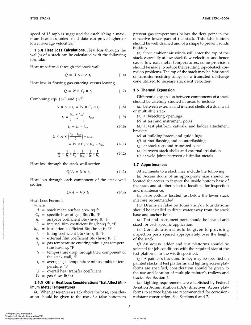
1.5.4 Heat Loss Calculations. Heat loss through thewall(s) of a stack can be calculated with the followingformula:
Heat transferred through the stack wall
Q p U � A � ts (1-6)
Heat loss in flowing gas entering versus leaving
Q p W � Cp � tg (1-7)
Combining eqs. (1-6) and (1-7)
U � A � ts p W � Cp � tg (1-8)
ts p �tin + tout
2 � − tamb (1-9)
tg p tin − tout (1-10)
U � A � �tin + tout
2 � − tamb
p W � Cp � (tin − tout) (1-11)
1U
p1hi
+1ha
+1
hins+
1hl
+1ho
(1-12)
Heat loss through the stack wall section
Q/A p U � ts (1-13)
Heat loss through each component of the stack wallsection
Q/A p h � th (1-14)
Heat Loss Formulawhere
A p stack mean surface area, sq ftCp p specific heat of gas, Btu/lb, °Fha p airspace coefficient Btu/hr-sq ft, °Fhi p internal film coefficient Btu/hr-sq ft, °F
hins p insulation coefficient Btu/hr-sq ft, °Fhl p lining coefficient Btu/hr-sq ft, °Fho p external film coefficient Btu/hr-sq ft, °Ftg p gas temperature entering minus gas tempera-
ture leaving, °Fth p temperature drop through the h component of
the stack wall, °Fts p average gas temperature minus ambient tem-
perature, °FU p overall heat transfer coefficientW p gas flow, lb/hr
1.5.5 Other Heat Loss Considerations That Affect Min-imum Metal Temperatures
(a) When gases enter a stack above the base, consider-ation should be given to the use of a false bottom to
3
prevent gas temperatures below the dew point in thenonactive lower part of the stack. This false bottomshould be well drained and of a shape to prevent solidsbuildup.
(b) Since ambient air winds will enter the top of thestack, especially at low stack flow velocities, and hencecause low exit metal temperatures, some provisionshould be made to reduce the resulting top-of-stack cor-rosion problems. The top of the stack may be fabricatedof corrosion-resisting alloys or a truncated dischargecone utilized to increase stack exit velocities.
1.6 Thermal Expansion
Differential expansion between components of a stackshould be carefully studied in areas to include
(a) between external and internal shells of a dual wallor multi-flue stack
(b) at breeching openings(c) at test and instrument ports(d) at test platform, catwalk, and ladder attachment
brackets(e) at building braces and guide lugs(f) at roof flashing and counterflashing(g) at stack tops and truncated cone(h) between stack shells and external insulation(i) at weld joints between dissimilar metals
1.7 Appurtenances
Attachments to a stack may include the following:(a) Access doors of an appropriate size should be
located for access to inspect the inside bottom base ofthe stack and at other selected locations for inspectionand maintenance.
(b) False bottoms located just below the lower stackinlet are recommended.
(c) Drains in false bottoms and/or foundationsshould be installed to direct water away from the stackbase and anchor bolts.
(d) Test and instrument ports should be located andsized for each specific application.
(e) Consideration should be given to providinginspection ports spaced appropriately over the heightof the stack.
(f) An access ladder and test platforms should beselected for job conditions with the required size of thetest platforms in the width specified.
(g) A painter’s track and trolley may be specified onpainted stacks. If test platforms and lighting access plat-forms are specified, consideration should be given tothe use and location of multiple painter’s trolleys andtracks. See Section 6.
(h) Lighting requirements are established by FederalAviation Administration (FAA) directives. Access plat-forms to service lights are recommended for corrosion-resistant construction. See Sections 6 and 7.
Copyright ASME International Provided by IHS under license with ASME
Not for ResaleNo reproduction or networking permitted without license from IHS
--`,,```,,,,````-`-`,,`,,`,`,,`---
//^:^^#^~^^""~:@":^*^~$~"#:*~:*@
^:#^#:~~^^~:^":^@::~*\\

ASME STS-1–2006 STEEL STACKS
(i) Rain caps are generally not required on full-timeactive stacks. When specified, a diameter of two timesthe stack diameter and a clear height of one stack diame-ter is recommended.
(j) Stack spark-arresting screens of stainless steelmaterial a minimum of two stack diameters high maybe specified when needed.
(k) Metal stacks require no lightning protection otherthan proper grounding at the base per NFPA require-ments. See section 7.
(l) Stack internal shutoff dampers and stack capdampers demand special consideration when specified.
(m) Straightening vanes to distribute flowing gas foreffective testing should be specified as required.
(n) Splitter baffles are sometimes used when twostack inlets enter the stack opposite each other to reduceback pressure in the event that isolation dampers arenot used.
(o) Gin pole or davit lifts are sometimes specified forhoisting instruments to the test platform.
(p) Top of stack roofs for multiple flue stacks anddual wall stacks should provide proper weather protec-tion for the inside surfaces, while at the same time pro-viding for expected differential expansion between fluesand the stack outer shell. Consideration should be givento the effect of the buildup of ash on any flat surfaces.
(q) Noise pollution control may require acousticalsuppressing sound attenuators within the stack.
1.8 Mechanical Section Symbols
A p stack mean surface area, sq in.B p barometric pressure — mercury absolute, in.
Cp p specific heat of gas Btu/lb, °FDi p inside diameter(s) of stack sections, ftDt p inside diameter of stack at outlet, ft
DRN p stack natural draft — water gage, in.d p density of gas, lb/ft2
F p friction factor based on Reynolds numberFLex p stack exit loss — water gage, in.FLf p stack friction loss — water gage, in.
FLen p stack entrance loss — water gage, in.HE p stack height above center line inlet, ftha p airspace coefficient Btu/hr-sq ft, °Fhi p internal film coefficient Btu/hr-sq ft, °F
hins p insulation coefficient Btu/hr-sq ft, °Fhl p lining coefficient Btu/hr-sq ft, °Fh0 p external film coefficient Btu/hr-sq ft, °FK p constant for breeching inlet angle
TA p absolute temperature of atmosphere, °RTG p average absolute temperature of gas, °R
tg p gas temperature entering minus gas tempera-ture leaving, °F
th p temperature drop through the h component ofthe stack wall
ts p average gas temperature minus ambient tem-perature, °F
4
U p overall heat transfer coefficientV p gas velocity at stack inlet, ft/secW p mass flow rate of gas, lb/hr
1.9 Mechanical Section Definitions
appurtenances: stack specialty design items apart fromshell and structural members.
cladding: thin metal overlaid over the base metal metal-lurgically and integrally bonded to the base metal.
EPA: Environmental Protection Agency (may be Federal,State, or local) government regulatory authority.
EPRI: Electric Power Research Institute.
false bottom: a cone or plate located just below thebreeching opening to prevent gases from entering thelower section of stack.
NFPA: National Fire Protection Association.
test zone: section of stack designed for testing. The loca-tion of test ports in relationship to upstream and down-stream flow pattern disturbances is well documented inFederal and State air quality rules and regulations.
truncated cone: a converging section reducing the exitdiameter located at the top of the stack.
2 MATERIALS
2.1 Scope
Material specifications are intended to cover singleor double wall stacks that are free-standing and self-supporting, guy or cable supported, or supported bystructural steel braces or framework. Reference is madeto the 1975 edition of Design and Construction of SteelChimney Liners, published by the American Society ofCivil Engineers.
2.2 Materials
The Materials listed in the following sections are sug-gested for use based on their ability to meet the physical,mechanical, chemical, and environmental requirementsof a given application. Acceptance of a material for aspecific application must be based on service experienceor independent verification of its suitability.
2.2.1 General Considerations(a) Materials shall conform to the applicable require-
ments in the sections hereinafter detailed.(b) The contractor shall submit one copy of the chemi-
cal-composition and mechanical-property mill testreports for all steels used to the owner for approval priorto construction unless otherwise indicated.
(c) When required for testing purposes, the contractorwill furnish the owner with identified scrap samples ofthe shell plates.
Copyright ASME International Provided by IHS under license with ASME
Not for ResaleNo reproduction or networking permitted without license from IHS
--`,,```,,,,````-`-`,,`,,`,`,,`---
//^:^^#^~^^""~:@":^*^~$~"#:*~:*@^:#^#:~~^^~:^":^@::~*\\

STEEL STACKS ASME STS-1–2006
(d) This section does not apply to linings and coatingsof stacks. See section 3.
(e) Corrosion allowances shall be considered (typi-cally 1⁄16 in. to 1⁄8 in.) where carbon, high-strength, lowalloy, and alloy steels are used. Experience or the resultsof tests should be used when selecting an allowance.
2.2.2 Shell and Base Plates. For more informationon this subject, see Tables B-1 through B-11 in Nonman-datory Appendix B.
(a) Shell and base plates typically may be of one ormore of the following structural quality materials:
(1) Carbon steels conforming to the ASTM A 36,A 283, or A 529 Specifications.
(2) High-strength, low alloy steels conforming tothe ASTM A 242, A 572, or A 588 Specifications.
(3) Stainless steels conforming to the ASTM A 666Specification.
(4) Stainless chromium-nickel steel clad plate con-forming to ASTM A 264 and nickel-base alloy clad steelconforming to ASTM A 265 may be considered for useas shell plate.
(5) Metals listed in Materials Appendix (i.e., Non-mandatory Appendix B), Table B-9 may be used notonly as sheet linings and cladding but also as solid platefor shell plates.
(b) Pressure vessel quality carbon steels such asASTM A 285, A 515, and A 516; alloy steels such asASTM A 387; and stainless steels such as ASTM A 240may be substituted for structural quality materials asappropriate.
(c) Carbon steels such as ASTM A 516, Grades 55through 70 and low alloy steels such as ASTM A 517,Grades A through T and ASTM A 537 are usually speci-fied for service temperatures as low as −50°F (−46°C).Nickel-containing alloy steels such as ASTM A 203,Grades A and B are usually used for service tempera-tures as low as −75°F (−59°C); and ASTM Grades D, E,and F are often used for service temperatures of −150°F(−101°C). Nickel-containing alloy steels and nickel stain-less steels are used for even lower temperatures. Suppli-ers of structural quality steels will provide data on notchtoughness when specified.
(d) Protection against corrosion and/or oxidationmay be required on interior and/or exterior surfacesdepending on the materials utilized and the conditionsencountered. Section 3 should be consulted and utilizedas appropriate.
(e) Creep rupture tensile stresses for sustained load-ing and high-temperature service conditions must beconsidered as given in para. 4.4.8.
2.2.3 Stiffeners and Structural Braces and/orFramework
(a) Stiffeners and structural braces and/or frameworktypically may be of one or more of the following mate-rials:
5
(1) carbon steels conforming to the ASTM A 36,A 283, or A 529 Specifications
(2) high-strength, low alloy steels conforming tothe ASTM A 242, A 572, or A 588 Specifications
(3) stainless steels conforming to the ASTM A 240or A 666 Specifications or nickel-containing alloys hav-ing compositions similar to those of the shell plate
(b) Protection may be required against corrosion forcomponents exterior to the shell and against corrosionand/or oxidation for components on the shell interior.Section 3 should be consulted and utilized as appro-priate.
2.2.4 Guy Wires, Cables, or Fittings(a) Guy wires and cables typically may be of one
or more of the following materials, and considerationshould be given to the initial stretch of the material:
(1) aluminum-coated steel wire strand conformingto the ASTM A 474 Specification
(2) zinc-coated (galvanized) steel wire strand con-forming to the ASTM A 475 and A 586 Specifications
(3) zinc-coated (galvanized) steel wire rope con-forming to the ASTM A 603 Specification
(4) stainless steel wire strand conforming to theASTM A 368 Specification
(b) Fittings for guys and cables should comply withmanufacturers’ standards and be of aluminum-coated,zinc-coated (galvanized), or stainless steel as appro-priate. Aluminum and zinc coating weights and stain-less steel grade should match those of the guys or cableson which they are used.
2.2.5 Anchor Bolts, Washers, and Nuts(a) Anchor bolts may be of threaded bolt and stud
stock normally used as connectors, or of round stockof structural material that may be threaded. They aretypically one of the following specifications:
(1) carbon steel threaded fasteners conforming tothe ASTM A 307 Specification
(2) carbon steel bolts for general applications con-forming to the ASTM A 449 Specification
(3) alloy steel bolts, studs, and threaded fastenersconforming to the ASTM A 354 Specification
(4) alloy steel bolts and studs with enhanced impactproperties conforming to the ASTM A 687 Specification
(5) carbon steel conforming to the ASTM A 36 Spec-ification
(6) high-strength, low alloy steels conforming tothe ASTM A 572 or A 588 Specification
(b) Material for washers shall conform to theASTM F 436 Specification and correspond to the anchorbolt material.
(c) Material for nuts shall conform to the ASTM A 563Specification and correspond to the anchor bolt material.
(d) Protection against corrosion may be required. Sec-tion 3 should be consulted and utilized as appropriate.
Copyright ASME International Provided by IHS under license with ASME
Not for ResaleNo reproduction or networking permitted without license from IHS
--`,,```,,,,````-`-`,,`,,`,`,,`---
//^:^^#^~^^""~:@":^*^~$~"#:*~:*@^:#^#:~~^^~:^":^@::~*\\

ASME STS-1–2006 STEEL STACKS
(e) Double nutting or an appropriate locking deviceis recommended.
2.2.6 Bolts, Washers, and Nuts(a) Unless otherwise specified, carbon and high-
strength steel bolts conforming to the ASTM A 307,A 325, or A 449 Specifications will be utilized.
(b) High-strength alloy steel bolts may be requiredand these should conform to the ASTM A 354 or A 490Specifications.
(c) For high-temperature applications, bolt materialshould conform to the ASTM A 193 B7 Specificationcovering alloy and stainless steels. Stainless steel boltsare also covered under the ASTM F 593 Specification.
(d) Unless otherwise specified, nuts should conformto the ASTM A 563 Specification. Stainless/heat resistingnuts shall be of a material corresponding to that of thebolt unless galling/seizing considerations dictateotherwise.
(e) Washers shall conform to the ASTM F 436 Specifi-cation. Stainless/heat resisting washers shall be of amaterial corresponding to that of the bolt.
(f) Protection from corrosion may be required. Section3 should be consulted and utilized as appropriate.
2.2.7 Appurtenances(a) Ladders, cages, and stairs may be constructed of
one or more of the following materials:(1) structural steels and stainless steels conforming
to the standards under para. 2.2.2(a)(2) carbon steel sheet and strip conforming to the
ASTM A 569 and A 570 Specification(3) high-strength, low alloy sheet and strip con-
forming to the ASTM A 606 and A 607 Specification(b) Platforms and grating may be constructed of one
or more of the following materials:(1) materials under 2.2.7(a)(2) stainless steels conforming to the ASTM A 666
Specification(3) aluminum conforming to the ASTM B 221 Speci-
fication. Reference is made to the National Associationof Architectural Metal Manufacturers (NAAMM) Man-ual for metal bar grating and stair treads
(c) Handrails, toe plates, etc., typically are made ofone of the following materials:
(1) carbon structural steel conforming to the ASTMA 36 or A 20 Specifications
(2) high-strength, low alloy steel conforming to theASTM A 242, A 588, or A 618 Specifications
(3) aluminum conforming to the ASTM B 221 Speci-fication
(4) stainless steels conforming to the ASTM A 666and A 554 Specifications
(d) Access doors, instrument and sampling ports(1) Access doors shall be of a material matching
the shell plates or cast iron.
6
(2) Instrument and sampling ports shall be of amaterial of matching or higher alloy content than theshell plates.
(e) Painter’s trolley and ring(1) A painter’s trolley and ring may be of carbon
steel or high-strength, low-alloy steels as specified underpara. 2.2.3 provided suitable corrosion protection isapplied.
(2) Ring also may be of a material such as Type 304or Type 316 stainless steel conforming to the ASTMA 240 or A 666 Specifications. Adequate structural sup-ports are to be provided.
(f) Stack Rain Caps(1) Unless otherwise specified, stack rain caps shall
be of the same composition as the stack shell.(2) Because of potential corrosion problems, stain-
less steel conforming to the ASTM A 240 Specificationor higher alloyed, corrosion-resistant materials shouldbe considered.
(g) Drain Systems. A system should be provided forcollecting and routing rain and condensate from theinterior of the stack to a single collection point at gradelevel 2. Drain pipe shall be of corrosion-resistant materialsuch as Type 304 or Type 316 stainless steel conformingto the ASTM A 240 or A 666 Specifications, nickel alloyor plastic.
2.2.8 Welding Electrodes(a) AWS D1.1, Structural Welding Code Steel is usu-
ally specified for structural welding of steel stacks. Asan alternative, ASME BPVC, Section IX, QualificationStandard for Welding and Brazing Procedures, Welders,Brazers, and Welding and Brazing Operations may bespecified.
(b) Welding electrodes with a minimum tensilestrength of 70 ksi are to be used for carbon steel applica-tions in steel stack construction. The type of electrodespecified is a function of the welding process to be used.
(c) For high-temperature applications, above 750°F(400°C), using high-strength, low-alloy steels, weldingelectrodes with a minimum tensile strength of 80 ksi areto be used.
(d) For steel stack construction using alloy steels, suchas ASTM A 335 and A 387, E8018-B2L electrode withwelding procedures conforming to AWS D10.8, Recom-mended Practice for Welding of Chromium-Molybde-num Steel Piping and Tubing should be used.
(e) When stainless steels and nickel alloys are used asplate, sheet, or as clad plate, the following specificationsapply:
(1) ANSI/AWS A5.4, Specification for StainlessSteel Electrodes for Shielded Metal Arc Welding
(2) ANSI/AWS A5.9, Specification for Bare Stain-less Steel Welding Electrodes and Rods
(3) ANSI/AWS A5.11, Specification for Nickel andNickel Alloy Welding Electrodes for Shielded Metal ArcWelding
Copyright ASME International Provided by IHS under license with ASME
Not for ResaleNo reproduction or networking permitted without license from IHS
--`,,```,,,,````-`-`,,`,,`,`,,`---
//^:^^#^~^^""~:@":^*^~$~"#:*~:*@^:#^#:~~^^~:^":^@::~*\\
STEEL STACKS ASME STS-1–2006
(4) ANSI/AWS A5.14, Specification of Nickel andNickel Alloy Bare Welding Electrodes and Rods
(5) ANSI/AWS A5.1, Specification for CoveredCarbon Steel Arc Welding Electrodes
(6) ANSI/AWS A5.18, Specification for CarbonSteel Filler Metals for Gas Shielded Arc Welding
(7) ANSI/AWS A5.20, Specification for CarbonSteel Electrodes for Flux Cored Arc Welding
(f) When welds are made between dissimilar metals,the type of electrode to be used should be based on thehigher grade material being welded.
(g) As with the design of the stack metal, proper con-sideration must be given to the reduction in weld metalstrength when exposed to high temperatures. The tem-perature-based strength reductions for the weld metalshould be assumed to be the same as that for the basemetal.
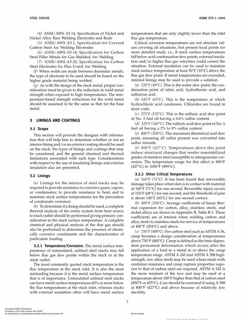
3 LININGS AND COATINGS
3.1 Scope
This section will provide the designer with informa-tion that will help him to determine whether or not aninterior lining and/or an exterior coating should be usedon the stack, the types of linings and coatings that maybe considered, and the general chemical and thermallimitations associated with each type. Considerationswith respect to the use of insulating linings and exteriorinsulation also are presented.
3.2 Linings
(a) Linings for the interior of steel stacks may berequired to provide resistance to corrosive gases, vapors,or condensates; to provide resistance to heat; and tomaintain stack surface temperatures for the preventionof condensate corrosion.
(b) To determine if a lining should be used, a completethermal analysis of the entire system from heat sourceto stack outlet should be performed giving primary con-sideration to the stack surface temperature. A completechemical and physical analysis of the flue gas shouldalso be performed to determine the presence of chemi-cally corrosive constituents and the characteristics ofparticulate loading.
3.2.1 Temperature/Corrosion. The metal surface tem-peratures of uninsulated, unlined steel stacks may fallbelow flue gas dew points within the stack or at thestack outlet.
The most commonly quoted stack temperature is theflue temperature at the stack inlet. It is also the mostmisleading because it is the metal surface temperaturethat is of importance. Uninsulated unlined steel stackscan have metal surface temperatures 60% or more belowthe flue temperatures at the stack inlet, whereas stackswith external insulation often will have metal surface
7
temperatures that are only slightly lower than the inletflue gas temperature.
Critical corrosion temperatures are not absolute val-ues covering all situations, but present focal points formore detailed study, i.e., if stack surface temperaturesfall below acid condensation dew points, external insula-tion and/or higher flue gas velocities could correct thesituation. External insulation can be used to maintainstack surface temperature at least 50°F (10°C) above theflue gas dew point. If metal temperatures are exceeded,internal linings may be used to provide a solution.
(a) 120°F (49°C). This is the water dew point, the con-densation point of nitric acid, hydrofluoric acid, andsulfurous acid.
(b) 145°F (63°C). This is the temperature at whichhydrochloric acid condenses. Chlorides are found inmost coals.
(c) 275°F (135°C). This is the sulfuric acid dew pointof No. 2 fuel oil having a 0.6% sulfur content.
(d) 320°F (160°C). The sulfuric acid dew point of No. 6fuel oil having a 2% to 8% sulfur content.
(e) 400°F (204°C). The maximum theoretical acid dewpoint, assuming all sulfur present was converted intosulfur trioxide.
(f ) 800°F (427°C). Temperatures above this pointinduce structural changes that render nonstabilizedgrades of stainless steel susceptible to intergranular cor-rosion. The temperature range for this effect is 800°F(427°C) to 1650°F (899°C).
3.2.2 Other Critical Temperatures(a) 160°F (71°C). It has been found that irreversible
damage takes place when skin is in contact with materialat 160°F (71°C) for one second. Reversible injury occursat 154°F (68°C) for one second, and the threshold of painis about 140°F (60°C) for one second contact.
(b) 400°F (204°C). Average coefficients of linear ther-mal expansion for carbon, alloy, stainless steels, andnickel alloys are shown in Appendix B, Table B-1. Thesecoefficients are of interest when welding carbon andalloy steels to stainless steels for service at temperaturesof 400°F (204°C) and above.
(c) 750°F (400°C). For carbon steel such as ASTM A 36,creep becomes a design consideration at temperaturesabove 750°F (400°C). Creep is defined as the time-depen-dent permanent deformation which occurs after theapplication of a load to a metal in or above the creeptemperature range. ASTM A 242 and ASTM A 588 high-strength, low-alloy steels may be used where steels withoxidation resistance and creep rupture properties supe-rior to that of carbon steel are required. ASTM A 242 isthe more resistant of the two and may be used at atemperature about 100°F higher than that of carbon steel(850°F or 455°C). Care should be exercised if using A 588at 800°F (427°C) and above because of relatively lowductility.
Copyright ASME International Provided by IHS under license with ASME
Not for ResaleNo reproduction or networking permitted without license from IHS
--`,,```,,,,````-`-`,,`,,`,`,,`---
//^:^^#^~^^""~:@":^*^~$~"#:*~:*@^:#^#:~~^^~:^":^@::~*\\

ASME STS-1–2006 STEEL STACKS
(d) 850°F (455°C). The temperature at which creepbecomes important for alloy steels.
(e) 1050°F (565°C). The temperature at which creepbecomes important for chromium-nickel austeniticstainless steels.
(f) 1150°F (620°C) to 2000°F (1093°C). The temperaturerange over which the stainless steels depending on theiralloy content, provide useful resistance to scaling. Referto Nonmandatory Appendix B, Table B-17 for informa-tion on maximum temperatures for alloy and stainlesssteels to avoid excessive scaling.
3.2.3 Environmental Severity Levels. See Nonmanda-tory Appendix C, Table C-1.
(a) Chemical Environment. Constituents within the fluegas that will affect the corrosivity of the environmentand thereby the suitability of linings include oxides ofsulfur (SOx), oxides of nitrogen (NOx), chlorides (Cl),and fluorides (F).
(1) Mild. Flue surface temperatures above acid dewpoints (pH p 4 to 8)
(2) Moderate. Flue surface temperatures below aciddew points on an intermittent basis, but normally abovethe acid dew points (pH p 2 to 4)
(3) Severe. Flue surface temperatures below the aciddew points for all operating cycles (pH p less than 2)
(b) Temperature Environments. Temperature levels alsocontribute to the severity of the environment particularlyas they relate to the suitability of organic linings. Tem-peratures that remain constant or steady may be less ofa problem than those that are cyclic.
(1) Mild. Temperatures up to, but not exceeding,200°F (93°C)
(2) Moderate. Temperatures from 200°F (93°C) to350°F (177°C)
(3) Severe. Temperatures greater than 350°F (177°C)
3.2.4 Classifications of Linings. See NonmandatoryAppendix C, Table C-1 and Table C-2.
3.2.4.1 Organic Linings. Most acid-resistant organiclinings fail or lose their flexibility and ability to resistliquid or vapor penetration at temperatures over 300°F(149°C). Some manufacturers claim that their productscan perform up to 500°F (260°C). Often-times, the combi-nation of the chemical environment, together with thetemperature environment, will be synergistic in nature,and require more careful selection of a lining. Beforechoosing a particular lining, the designer should contactthe manufacturer to ensure the suitability of the productfor the requirements at hand.
(a) Organic resin. Polyester, novolac phenolic epoxy,novolac epoxy, epoxy, vinyl ester, etc. Linings comprisedof chemical resinous compounds based on carbon chainsor rings, and also containing hydrogen with or withoutoxygen, nitrogen, and other elements. The formulationsincorporate hardening agents to cure the resins, andusually fillers or reinforcement to provide desirable
8
physical properties. Application is in liquid form (solu-tion, dispersion, etc.) using spray, roller, or trowel.
(b) Organic elastomers. Fluoropolymers, natural rub-ber, butyl rubber, and urethane asphalts, etc. Liningsbased on natural or synthetic polymers which, at roomtemperature, return rapidly to their approximate initialdimension and shape after substantial deformation bya weak stress and subsequent release of that stress.Application is in sheet or liquid form.
Due to the great number of variations of formulationsby manufacturers of organic linings, this document willnot be more specific in this regard. There are ASTMstandards that can be used to evaluate certain propertiesof organic linings, and where standards do not exist orwhen further information is needed regarding specificproducts, their performance, and recommended usagesare required, the linings manufacturers should be con-tacted.
3.2.4.2 Inorganic Linings(a) Inorganic Cementitious Concrete Monolithics. Lin-
ings comprised of materials other than hydrocarbonsand their derivatives. These protective barriers are com-prised of inert mixtures of chemically inert, solid aggre-gate fillers and a cementing agent. The cementing agentmay be an acid-setting agent contained in the powderand a silicate binder, which subsequently hardens bythe chemical reaction between the setting agent and thesilicate binder, or a high alumina cement binder thathardens by hydration. Application is by troweling, cast-ing, or Guniting. Refractory installation quality controlguidelines, monolithic refractory linings inspection andtesting, and materials used shall be in accordance withAPI RP 936. Included are the following:
(1) Acid-Resistant Concrete. These linings are basedon silicate chemical setting cements and utilize chemi-cally inert fillers. Particularly suited for severe chemicalenvironments and mild/moderate temperature environ-ments.
(2) Acid-Alkali-Resistant Concrete. These linings aregenerally based on a combined silicate, chemically-resis-tant cement, with inert aggregate fillers. Particularlysuited under moderate chemical environments andmild/moderate temperature environments.
(3) Refractory Concrete. These linings are typicallybased on high alumina, hydraulically-setting cementbinders, utilizing inert refractory-type aggregate fillers.Suitable for mild chemical environments and severetemperature environments.
(4) Insulating Concrete for Temperatures to 650°F(899°C). Typical formulations include: expanded clay,slag, or fuel ash, combined with a high alumina hydrau-lic cement binder; a calcined diatomite aggregate fillerand high alumina cement; a perlite or vermiculite aggre-gate filler combined with a high alumina cement binder.Suited for application where temperature is the mainenvironmental condition to be addressed.
Copyright ASME International Provided by IHS under license with ASME
Not for ResaleNo reproduction or networking permitted without license from IHS
--`,,```,,,,````-`-`,,`,,`,`,,`---
//^:^
^#^~
^^""
~:@
":^*^
~$~"
#:*~
:*@
^:#^
#:~~
^^~:
^":^
@::~
*\\

STEEL STACKS ASME STS-1–2006
(5) Insulating Concrete for Temperatures up to 2200°F(1204°C). Linings are based on high-temperature insulat-ing aggregate fillers utilizing a high alumina hydraulicsetting cement binder. Particularly suited where the tem-perature environment and insulation characteristics ofthe lining are important.
(b) Inorganic Masonry. Linings comprised of nonme-tallic, chemically inert masonry units, such as brick orfoamed, closed, cellular glass block, bonded togetherwith a mortar having adequate adhesion to the units,and possessing suitable chemical and thermal resistancefor the anticipated exposure. Included are the following:
(1) Foamed, Closed, Cellular Glass Block. Linings con-structed of this unit are highly insulative. Borosilicate-type glass compositions are most suited for withstand-ing severe chemical environments and severe tempera-ture environments as defined by this Standard.
(2) Firebrick. Linings of brick having appropriatealumina content to be chemically and physically stableat high temperatures, and installed with a suitablerefractory mortar, may be used to temperatures of 2200°F(1204°C).
(3) Acid-Resistant Brick. These linings are con-structed of chemically-resistant bricks, which are nor-mally laid in chemical-resistant mortar for use wherethere are severe chemical and thermal environments.The acid-resisting brick should be specified in accor-dance with either ASTM C 279 or ASTM C 980.
(4) Insulating Firebrick Linings. These linings arecomprised of lightweight, porous refractory brick hav-ing much lower thermal conductivity and heat storagecapacity than firebrick and installed with high-tempera-ture refractory mortars and used in very high-tempera-ture environments where insulation quality is desirable.
3.2.4.3 Metallic Linings and Cladding. See Non-mandatory Appendix C, Table C-1.
Metallic linings and cladding should be considered foruse whenever resistance to corrosion and/or elevatedtemperature is a concern. High performance metals andalloys including stainless steels, nickel-based alloys andtitanium are available for use as linings or as claddingon carbon-steel plate. Usually, the metallic linings are1⁄16 in. (1.6 mm) thick although thickness of 1⁄8 in. (3.2 mm)also are used. Cladding thickness can range from 5% to50% of the total plate thickness, but for light gauge, 1⁄4-in. (6.4 mm) carbon steel, the preferred thickness is 1⁄16in. (1.6 mm) or 25% of the total plate thickness. Metalliclinings are applied to the substrate and welded togetherby the overlap joint method as described in NACE Stan-dard Recommended Practice RP0292-98. Metal claddingis applied to carbon steel plate by either the hot, sand-wich-rolling process or the explosive bonding process.The roll-bonded clad-plate product with the claddingmetallurgically bonded to the carbon steel is availablefrom the mill. Clad plate may be installed as describedin NACE Standard Recommended Practice RP0199-99.
9
When selecting stainless steels and nickel alloys forcorrosive applications, a brief description of the effectsof some of the alloying elements may be helpful. Chro-mium (Cr) is most important from the standpoint ofdeveloping the passive or protective film which formson the surface of the alloy in air or oxidizing environ-ments. Nickel (Ni) is important in that it helps to expandthe passivity limits of the alloy thereby contributing toimproved corrosion resistance. It also is responsible forthe maintenance of the desirable austenitic microstruc-ture, which provides good ductility, fabricability, andweldability. Molybdenum (Mo) is the most importantelement for providing pitting and crevice corrosionresistance, and nitrogen (N) and tungsten (W) are help-ful in this regard. Nitrogen also increases the strengthof the alloy and helps to maintain the austenitic micro-structure. ASTM G 48 offers standard test methods forevaluating pitting and crevice corrosion resistance inchloride environments.
The most important element for increasing oxidation(corrosion) resistance of steels at temperatures of 1,000°F(538°C) and above is chromium. Other elements suchas silicon (Si), aluminum (Al) and the rare earth elementssuch as cerium (Ce) also increase oxidation resistance,particularly when added to alloys containing chromium.
To avoid intergranular corrosion in certain acidic envi-ronments, intergranular carbide precipitation (ICP)resulting from welding must be prevented. ICP can beprevented by the use of low-carbon (L) grades (less than0.03 C) or the addition of stabilizing elements such astitanium (Ti) and columbium (Cb).
3.3 Coatings
(a) The terms paint and coating are sometimes difficultto differentiate. The term coating is a more generic classi-fication that includes paint. While the primary functionof a coating is to provide protection, a paint may havethe additional function of color along with protection.The color properties of a paint may be more importantthan the protective properties. In this document, theword coating will also mean paint.
Stacks that are constructed of carbon steel may requirecoatings to protect the steel from corrosion by the atmo-spheres to which it is exposed; to provide an aestheticallypleasing structure; and to be in accordance with under-writer codes and government regulations pertaining toaviation safety. Some low alloy steels, such as ASTMA 242 and A 588 exhibit superior atmospheric corrosionresistance to carbon steels and may not require an exte-rior coating depending on the corrosivity of the atmo-sphere. Stacks that are constructed of stainless steel orhigher alloys should be resistant to atmospheric cor-rosion.
(b) Since a stack is subjected to outdoor exposure,careful consideration for sunlight and weathering must
Copyright ASME International Provided by IHS under license with ASME
Not for ResaleNo reproduction or networking permitted without license from IHS
--`,,```,,,,````-`-`,,`,,`,`,,`---
//^:^^#^~^^""~:@":^*^~$~"#:*~:*@
^:#^#:~~^^~:^":^@::~*\\

ASME STS-1–2006 STEEL STACKS
be given, together with an awareness of discoloration,fading, brittleness, etc.
(c) In assessing the corrosive effects of the environ-ment, careful consideration should be given to the topportion of the stack where washdown may create a moresevere condition.
(d) The type of coating required will depend uponthe color, pigmentation, maximum temperature reachedby the steel skin, and the duration of the higher tempera-tures.
(e) The majority of heat-resistant coatings use heat-resistant pigments, either inorganic or metallic.
(f) In coating steel stacks, water-based paints or emul-sions have not shown good performance, and tend toexhibit bleeding.
3.3.1 Classification of Coatings. See NonmandatoryAppendix C, Table C-2.
(a) Oil-Based Coating System. Such a coating system issuitable for providing excellent protection when sub-jected to outside rural weather conditions, but only pro-tects against very mild industrial fumes and mild marineenvironments. This coating system is not recommendedfor corrosive environments. It tends to exhibit very slowdrying characteristics in curing, and embrittles and yel-lows with aging.
(b) Alkyd Coating System. This type of coating showsexcellent resistance to weathering in rural environments.It shows poor acid chemical resistance, and shows onlyfair performance in marine salt environments. This sys-tem is easy to apply, exhibits good color retention andgloss, is economical, and is easy to recoat. However, itis very limited in its usage.
(c) Phenolic Coating System. This system is excellent inmoderate/severe chemical corrosive atmospheres, andexhibits good weathering resistance. It shows excellentresistance in very humid environments.
(d) Vinyl Coatings. These coatings are normally usedin severe chemical environments, and not usually usedas stack coatings because they are expensive. However,these coatings do exhibit excellent resistance to weather-ing, and provide a good degree of flexibility.
(e) One-Coat Shop Painting for Structural Steel. Thistype of coating is not for protecting steel exposed toweathering for greater than a six-month period even innormal rural or mild industrial environments, or marineexposures.
(f) Coal-Tar Epoxy Coating. Used extensively in marineand chemical environments. These coatings have a ten-dency to embrittle during early years of exposure and,hence, require relatively rigid substrate to show goodperformance. They are less expensive than the two-com-ponent epoxies, normally black in color, and require anSSPC-PC#5 surface preparation.
10
(g) Zinc-Rich Painting Systems (Inorganic). This coatingprovides excellent protection to the steel from weather-ing and is suited for high humidity and marine atmo-spheres. It is not particularly suited for acid resistance.However, when it is top-coated, it provides good resist-ance to exposure to chemical fumes. It requires an SSPC-SP#10 minimum surface preparation with a surface pro-file of 1 to 2 mils in order to obtain total adhesion.
(h) Epoxy Coating System. This coating provides goodresistance to industrial fumes and marine atmosphereexposures. These coatings exhibit good flexibility, hard-ness, toughness, and are of a high solids content.Although they tend to chalk quickly under weathering,they retain excellent chemical resistance.
(i) Novolac Epoxy System. This coating provides excel-lent resistance to industrial fumes and marine atmo-sphere exposures. These coatings exhibit good flexibility,hardness, toughness, and are of 100% solids content.They have a higher temperature resistance than an epoxysystem and better chemical resistance.
(j) Novolac Phenolic Epoxy System. This coating pro-vides excellent resistance to industrial fumes and marineatmosphere exposures. These coatings exhibit flexibility,hardness, excellent toughness, and are of 100% solidscontent. They have a higher temperature resistance thannovolac epoxy systems and better chemical resistance.
(k) Chlorinated Rubber. This coating is similar to a vinyland provides a good tough film, which has good abra-sion resistance and possesses excellent weathering char-acteristics. It also shows excellent resistance to mineralacids and to marine environments in salt water. Nor-mally limited to 160°F (71°C) performance temperature.
(l) Silicones. Silicones provide excellent heat resistanceand may be used up to 1,200°F (649°C). They have supe-rior exterior weathering, minimum film erosion, asshown by chalking resistance, gloss retention, and colorretention. They show good resistance to mild chemicalexposure. The properties depend upon the amount ofsilicone resin present and the type of modified agentused. Pure silicone, together with aluminum pigment,provides an excellent durable coating resistant to hightemperature, and is also expensive.
(m) Two-Component Urethane System. A two-compo-nent, catalyzed, cured aliphatic urethane provides ahard, tough, and abrasion-resistant coating, whichshows excellent weathering characteristics and glossretention. It also possesses good chemical resistance tomild acids and alkalis, and shows excellent adhesionto steel. However, during application, it tends to bemoisture-sensitive; yet, upon curing, it exhibits excellentresistance to humidity, marine environments, and mildcorrosive environments.
(n) Acrylics. These coatings show excellent color andgloss retention for outdoor application. However, theyare very limited in their chemical resistance. They areeconomical, and provide satisfactory performance in
Copyright ASME International Provided by IHS under license with ASME
Not for ResaleNo reproduction or networking permitted without license from IHS
--`,,```,,,,````-`-`,,`,,`,`,,`---
//^:^
^#^~
^^""
~:@
":^*^
~$~"
#:*~
:*@
^:#^
#:~~
^^~:
^":^
@::~
*\\

STEEL STACKS ASME STS-1–2006
rural environments, where there are nothing more thanvery mild fume conditions. They do not exhibit proper-ties as good as vinyl or chlorinated rubbers with respectto chemical resistance.
3.3.2 Important Coating Considerations(a) environment (rural, industrial, and marine)(b) exposure to temperature(c) weathering(d) aesthetic color retention(e) durability(f) surface preparation(g) cost(h) coating manufacturer’s recommendation
3.3.3 Curing Methods(a) Air oxidation (alkyds, epoxy)(b) Solvent evaporation (vinyls, chlorinated rubber,
coal-tar, and acrylics)(c) Chemical reaction (epoxies, polyurethanes, vinyl
esters, and inorganic zincs)(d) Heat cure (silicones and high-bake phenolics)
3.3.4 Primer(a) The primer is the most critical element in most
coating systems because it is responsible for preservingthe metallic state of the substrate, and it must anchorthe total coating system to the steel. Surface preparationis very important.
(b) In general, the more severe the environment, orthe longer the requirement for protection, the greaterthe coating dry-film thickness will be. Care should betaken, however, in the application of high build systemsto thin-walled structures and other dimensionally unsta-ble substrates. Thick films, particularly those of rigidthermal sets, are less able to provide the necessary flexi-bility to substrate movements (expansion and contrac-tion) than are thin films, and can easily undergoadhesive and cohesive failure leading to subsequent dis-bondment.
(c) It is to be noted that temperatures are to referto the exterior steel surfaces, and not to the flue gastemperatures within the stacks.
(d) For external steel surface temperatures between450°F (232°C) and 900°F (482°C), two coats of aluminumpigmented, silicone resin-based coatings have beenshown to provide excellent performance.
(e) For external steel surface temperatures between450°F (232°C) and 900°F (482°C), a zinc primer, followedby a top-finished coat of a modified silicone, has shownexcellent performance.
(f) All coatings should be applied in strict accordancewith the manufacturer’s instructions, observing mini-mum application temperatures, catalyst, type, additionrates and thinners, and the amounts allowed.
3.3.5 Design Considerations(a) Edges.
11
(b) Deep, square corners.(c) Discontinuous areas (bolt heads, corners, etc.).(d) Weld and weld spatter.(e) Skip welds.(f) Back-to-back angles.(g) Effective separation of faces of dissimilar metals.(h) Separation materials of suitable shape and thick-
ness (gaskets, butyl tape, etc.).(i) Structural materials, guy wires, cables, fittings,
bolts, nuts, washers, ladders, cages, grating, and otheraccessories may be protected from atmospheric corro-sion by the use of hot-dip galvanized coatings. Theseshould be applied in accordance with the ASTM A 153Specification, and should involve the appropriate coat-ing weight, Classes A, B, and C, which are in order ofincreasing zinc coating weight.
(j) Hot-dip galvanized coatings should not be usedon material in contact with unpainted A 242 or A 588steels.
(k) Because of potential corrosion problems with stackrain-caps, stainless steels conforming to the ASTM A 240Specification or higher alloy, corrosion-resistant materi-als should be considered in their construction.
(l) Galvanizing of such items as hand rails, ladders,and other items of suitable size and shape affords long-term protection in nonaggressive atmospheric environ-ments.
(m) Silicone coatings have been well-known for sometime for their good color and gloss retention whenexposed to exterior weathering. Unmodified siliconesare expensive, and must cure at 400°F to 500°F (204°Cto 260°C). Air drying properties, lower cost, and hard-ness in adhesion are obtained by copolymerizing sili-cones with organic polymers. The copolymers showpractically no film erosion and, therefore, are very slowto chalk.
(n) Inorganic zinc pigmented coatings, when prop-erly applied to blast-cleaned surfaces, show good resist-ance to atmospheric exposure.
3.3.6 Variations of Formulations. Due to the greatnumber of variations of formulations by coating manu-facturers, this document will not be more specific in thisregard. When standards do not exist, or when furtherinformation is needed regarding specific products, theirperformance, and recommended usages, the coatingmanufacturers should be contacted.
3.4 Corrosion
3.4.1 Attack Due to Sulfur Oxides [From the ModelCode on Steel Chimneys (CICIND)]
(a) The most common form of internal chemical attackis due to acids formed by the condensation of sulfuroxides in the flue gas. Sulfur is found in all solid andliquid fuels to varying degrees and can also be foundin gaseous fuels. During the combustion process, nearly
Copyright ASME International Provided by IHS under license with ASME
Not for ResaleNo reproduction or networking permitted without license from IHS
--`,,```,,,,````-`-`,,`,,`,`,,`---
//^:^^#^~^^""~:@":^*^~$~"#:*~:*@^:#^#:~~^^~:^":^@::~*\\

ASME STS-1–2006 STEEL STACKS
all sulfur in the fuel is oxidized to sulfur dioxide (SO2),which is absorbed by condensing water vapor to formsulfurous acid.
(b) A small quantity of sulfur dioxide (SO2) is oxi-dized to sulfur trioxide (SO3). The quantity depends ina complex manner upon the sulfur content of the fuel,the amount of excess air available during combustion,temperature in the combustion chamber, and the pres-ence of catalysts such as iron oxides. This small concen-tration of SO3 (usually measured in ppm) gives riseto most of the acid corrosion problems encountered inchimneys. This is because on condensation, the SO3 ionscombine with water vapor to form sulfuric acid, whoseconcentration can be as high as 85%.
(c) Condensation of these acids takes place when thetemperature of the flue gas falls below their acid dewpoint, or when the flue gas comes into contact with asurface at or below the relevant acid dew point temper-ature.
(d) The acid dew point temperature of sulfuric aciddepends upon the concentration of SO3 in the flue gas.Provided the temperature of the surfaces with whichthe flue gas can come into contact is maintained at least50°F (10°C) above the acid dew point estimated in Fig.C-1 in Nonmandatory Appendix C, there is no danger ofacid corrosion due to this cause. An adiabatic saturationcurve showing sulfuric acid concentrations for varioustemperatures and operating conditions together withsuggested material is shown in Fig. C-2 in Nonmanda-tory Appendix C.
(e) The acid dew point of sulfurous acid is about 120°F(49°C), a little above the water dew point. If the fuel iscontaminated, other acids, such as hydrochloric andnitric acid can be expected to condense in the sametemperature range. Thus, even if fuel and combustionprocesses are chosen to minimize production of SO3, orif flue gases are scrubbed to remove most of the SO3and SO2, severe corrosion can be expected if the tempera-tures of the flue gas, or the surfaces with which it cancome into contact, fall below 149°F (65°C), or the aciddew point temperature relevant to the reduced SO3 con-centration, if this is higher. Again, a safety margin of50°F (10°C) above the acid dew point is determined fromFigs. C-1 and C-2 in Nonmandatory Appendix C.
3.4.2 Attack Due to Chlorine, Chlorides, and Fluorides(a) Chlorides and fluorides may be found in all solid
fuels, including refuse, and in many liquid fuels. Uponcombustion, chlorides and fluorides are transformedinto free chloride and fluoride ions, respectively, which,on contact with water vapor, are transformed into hydro-chloric acid and hydrofluoric acid. The highest conden-sation temperature at which hydrochloric acid has beenfound is 140°F (60°C). The condensation temperaturefor hydrofluoric acid can be even lower. Thus, when anyflue surface falls below this acid dew point, very seriouscorrosion will occur. This dew point is close to that of
12
the water dew point and the sulfurous acid dew point.Therefore, even very small amounts of chlorides andfluorides, if allowed to concentrate such as under depos-its, can cause serious corrosion problems. For example,chloride levels under deposits have been found to be ashigh as 100,000 ppm necessitating the use of the mostcorrosion-resistant materials.
(b) Hydrogen chloride, hydrogen fluoride, and freechlorine in flue gases also become corrosive in theirvapor stage. Stainless steels are attacked at temperaturesabove 600°F (316°C). Fluoride vapors are corrosive tostainless steels at temperatures above 480°F (249°C).
3.4.3 Limited Acid Corrosion Exposure. Limited expo-sure to acid corrosion conditions can be permitted instacks, which, for most of the time, are safe from chemi-cal attack, provided the flue gas does not contain halo-gens (chlorine, chlorides, fluorides, etc.).
3.4.4 Critical Corrosion Factors(a) Air leaks(b) Fin cooling of flanges, spoilers, or other attach-
ments(c) Cooling through support points(d) Downdraft effects at top of the chimney
(1) presence of chlorides or fluorides in the flue gascondensate can radically increase corrosion rates
(2) regardless of temperatures, corrosion can occurif halogen concentrations exceed the following limits
(a) hydrogen fluoride: 0.025% by weight(300 mg/m3 at 20°C and 1 bar pressure)
(b) elementary chlorine: 0.1% by weight(1 300 mg/m3 at 20°C and 1 bar pressure)
(c) hydrogen chloride: 0.1% by weight (1 300mg/m3 at 20°C and 1 bar pressure)
3.5 Insulation, Jacketing, and Strapping
3.5.1 Insulation(a) Insulation may be required on the stack exterior
and/or interior, or between the walls of a dual wall stack.(b) Insulating linings are covered in para. 3.2.4.2.(c) There are numerous ASTM standards covering
thermal insulating materials and their properties. Thesestandards should be consulted and utilized in conjunc-tion with the manufacturers’ recommendations to meetthe application requirements.
3.5.2 Jacketing and Strapping(a) Jacketing may be of a material selected from one
of the following ASTM Specifications:(1) aluminum-coated steel conforming to A 463(2) galvanized steel conforming to A 527(3) stainless steel conforming to A 666(4) aluminum conforming to B 209
(b) Strapping may be of the same material as the jack-eting, but stainless steel is usually preferred.
Copyright ASME International Provided by IHS under license with ASME
Not for ResaleNo reproduction or networking permitted without license from IHS
--`,,```,,,,````-`-`,,`,,`,`,,`---
//^:^^#^~^^""~:@":^*^~$~"#:*~:*@
^:#^#:~~^^~:^":^@::~*\\

STEEL STACKS ASME STS-1–2006
4 STRUCTURAL DESIGN
4.1 Scope
This section includes currently acceptable methodsfor establishing structural configuration of steel stacksand stack elements to resist all external and internalloads imposed by the geography and topography of thesite and by operating conditions.
4.2 General
4.2.1 Limitations. The design recommendationsmade in the Standard are applicable primarily to circularsteel stacks.
4.2.2 Location. The stack design and constructionshall be appropriate to the specific site, with particularconsideration to local wind and seismic conditions, air-craft traffic, operating conditions, and local laws.
4.2.3 Drawings and Computations. Design drawingsof the stack and all appurtenances shall be preparedshowing all elements and details necessary for satisfac-tory fabrication and erection of the stack. Computationsshall be prepared and submitted. All means of connec-tion of material shall be specifically detailed with properdifferentiation between shop and field connections.
4.3 Applied Loading
4.3.1 Dead Load. The dead load shall consist of theweight of steel stack, coatings, internal liner, insulation,and cladding, and all permanent accessories such asladders, platforms, and gas sampling equipment. Fordead load, the full plate thickness shall be used. Thecorroded plate area shall be used for stress calculations.For stacks possessing refractory lining, the appliedweight of the refractory material shall be used to calcu-late dead load stresses.
4.3.2 Live Load. The minimum live load of 50 psfshall be included for platforms and walkways. This loadneed not be considered for wind or earthquake combina-tions. Consideration shall be given for accumulated ashloads, and moisture in the case of wet gases, on the stackwalls and floors.
4.3.3 Wind Load. The wind load shall be calculatedin accordance with procedures outlined in this section.The design shall also consider wind loads due to interfer-ence effects as stated in para. 4.3.3.7.
4.3.3.1 Design Wind Force. The design load distri-bution is given by
w(z) p w(z) + wD(z) (4-1)
where
w(z) pCf qz D
12(1 + 6.8Iz)(4-2)
13
and
wD(z) p3zM0
h3�Gf (1 + 6.8Iz) −1� (4-3)
The velocity pressure, qz, shall be calculated by:
qz p 0.00256 V2IKztKz (4-4)
where the basic wind speed (V) is based on a three-second gust velocity and is selected in accordance withthe provisions of para. 4.3.3.2 – para. 4.3.3.4, the impor-tance factor (I) is set forth in Tables I-2 and I-3 of Manda-tory Appendix I, and the velocity pressure exposurecoefficient (Kz) is given in Table I-4 of of MandatoryAppendix I in accordance with the provisions of paras.4.3.3.5 and 4.3.3.7. Provisions of para. 4.3.3.5 shall beused to determine Kzt where applicable, but Kzt shallnot be less than 1.0. The numerical coefficient 0.00256shall be used, except where sufficient climatic data areavailable to justify the selection of a different value ofthis factor for a specific design application. Interferenceeffects on the force coefficient (Cf) described in para.4.3.3.7 shall be considered.
The basic wind speed V used in the determination ofdesign wind loads is given in Fig. I-1 of MandatoryAppendix I, except as provided in paras. 4.3.3.2 through4.3.3.4.
4.3.3.2 Special Wind Regions. The basic windspeed shall be increased where records or experienceindicate that the wind speeds are higher than thosereflected in Fig. I-1 of Mandatory Appendix I. Mountain-ous terrain, gorges and special regions shown in Fig. I-1shall be examined for unusual wind conditions. Theauthority having jurisdiction shall, if necessary, adjustthe values given in Fig. I-1 to account for higher localwind speeds. Such adjustment shall be based on meteo-rological information and an estimate of the basic windspeed obtained in accordance with the provisions ofpara. 4.3.3.3.
4.3.3.3 Estimation of Basic Wind Speeds FromRegional Climatic Data. Regional climatic data shall onlybe used in lieu of the basic wind speeds given inFig. I-1 when
(a) approved extreme-value statistical-analysis proce-dures have been employed in reducing the data; and
(b) the length of record, sampling error, averagingtime, anemometer height, data quality, and terrain expo-sure have been taken into account.
4.3.3.4 Exposure Categories. An exposure categorythat adequately reflects the characteristics of groundsurface irregularities shall be determined for the site atwhich the building or structure is to be constructed.Account shall be taken of variations in ground surface
Copyright ASME International Provided by IHS under license with ASME
Not for ResaleNo reproduction or networking permitted without license from IHS
--`,,```,,,,````-`-`,,`,,`,`,,`---
//^:^^#^~^^""~:@":^*^~$~"#:*~:*@^:#^#:~~^^~:^":^@::~*\\

ASME STS-1–2006 STEEL STACKS
roughness that arises from natural topography and veg-etation as well as from constructed features. The expo-sure in which a specific building or other structure issited shall be assessed as being one of the followingcategories:
(a) Exposure A. Large city centers with at least 50% ofthe buildings having a height in excess of 70 ft. Use ofthis exposure category shall be limited to those areasfor which terrain representative of Exposure A prevailsin the upwind direction for a distance of at least 0.5miles or 10 times the height of the steel stack, whicheveris greater. Possible channeling effects or increased veloc-ity pressures due to the steel stack being located in thewake of adjacent buildings shall be taken into account.
(b) Exposure B. Urban and suburban areas, woodedareas, or other terrain with numerous closely spacedstructures having the size of single-family dwellings orlarger. Use of this exposure category shall be limited tothose areas for which terrain representative of ExposureB prevails in the upwind direction for a distance of atleast 1,500 ft or 10 times the height of the building orother structure, whichever is greater.
(c) Exposure C. Open terrain with scattered obstruc-tions having heights generally less than 30 ft. This cate-gory includes flat, open country and grasslands.
(d) Exposure D. Flat, unobstructed areas exposed towind flowing over open water for a distance of at least1 mile. This exposure shall apply only to those steelstacks exposed to the wind coming from over the water.Exposure D extends inland from the shoreline a distanceof 1,500 ft or 10 times the height of the stack, whicheveris greater.
4.3.3.5 Wind Speed Over Hills and Escarpments.The provisions of this paragraph shall apply to isolatedhills or escarpments located in Exposures B, C, or Dwhere the upwind terrain is free of such topographicfeatures for a distance equal to 50HH or 1 mile, whicheveris smaller, as measured from the point at which HHis determined. Wind speed-up over isolated hills andescarpments that constitute abrupt changes in the gen-eral topography shall be considered for steel stacks sitedon the upper half of hills and ridges or near the edgesof escarpments, illustrated in Fig. I-2 of MandatoryAppendix I, by using factor Kzt
Kzt p (1 + K1 K2 K3)2 (4-5)
where K1, K2, and K3 are given in Fig. I-2 of MandatoryAppendix I. The effect of wind speed-up shall not berequired to be considered when HH/Lh < 0.2, or whenHH < 15 ft for Exposure D, or 30 ft for Exposure C, or< 60 ft for all other exposures.
4.3.3.6 Gust Effect Factor. The gust effect factor Gffor main wind-force resisting systems of steel stacksshall be calculated in accordance with the equationsshown in Mandatory Appendix I.
14
4.3.3.7 Force Coefficient Interference Effect. Forgrouped or clustered stacks having a center-to-centerdistance of 3 diam. or less, an increase in the force coeffi-cient value of 20% is suggested in the absence of modelwind tunnel testing or existing full scale data.
4.3.4 Seismic Load. Lateral seismic forces shall beconsidered in accordance with the guidelines describedin this Section. The procedure provided shall be followedin the U.S. as a minimum requirement. It has been foundthat, due to the low mass of steel stacks, those onlyin high seismic areas or those containing high massdistribution are governed by seismic loads.
4.3.4.1 Earthquake Response. The steel stackresponse to earthquake can be determined using theresponse spectrum method by using a horizontalresponse spectrum based upon a maximum groundacceleration of 1.0g with a damping value of 0.05, whichis scaled to the specific site. The value of the acceleration,Av, related to the effective peak velocity, shall be deter-mined using Table D-2 in Nonmandatory Appendix Dor the published value for the location. Using the valueof Av, the response spectrum scaling ratio is found inTable D-2 in Nonmandatory Appendix D. Linear inter-polation may be used in between published values ofAv. The modal moment, shear, and deflection responseof each mode is scaled with the scaling ratio for thespecific frequency of each mode. Modal responses foreach mode are then added using the SRSS method (tak-ing the square root of the sum of the squares of modalmoment, shear deflection responses). In lieu of theresponse spectrum method, a static equivalent methodmay be used.
The mathematical model of the steel stack used in theanalysis shall be sufficiently detailed to represent thesteel stack, liner or coating, lateral support and founda-tion property and support conditions. A minimum of10 elements and 5 modes of vibration should be used.
An example of the mathematical calculation of modalproperties and response spectrum earthquake responseis shown in Nonmandatory Appendix D.
4.3.5 Thermal Loads. Nonuniform distribution of fluegas across the steel stack or steel stack liner may causedifferential temperatures. Unless the temperature distri-bution is uniform or linearly varying across the stack/liner diameter, thermal stresses will be induced in bothlongitudinal and circumferential directions. In addition,longitudinal bending stresses and shear stresses will beproduced if the stack shell or liner that is subjected tononuniform temperatures along its height is restrainedfrom lateral movements. The thermal stresses should beconsidered in applicable stack and liner designs. Referto 1975 ASCE Publication, Design and Construction ofSteel Chimney Liners for more discussion of thermaleffects.
Copyright ASME International Provided by IHS under license with ASME
Not for ResaleNo reproduction or networking permitted without license from IHS
--`,,```,,,,````-`-`,,`,,`,`,,`---
//^:^^#^~^^""~:@":^*^~$~"#:*~:*@^:#^#:~~^^~:^":^@::~*\\

STEEL STACKS ASME STS-1–2006
For stacks to be subjected to high-temperature(>500°F) and/or fast plant startup or shutdown such ascyclic operation of combustion turbine, design consider-ation should be given to minimize the nonuniform ther-mal differentials that may exist between shell andstiffeners or other structural elements. Localized thermalstresses induced in the inner plates and stiffeners canbe substantial and must be considered in the design.
4.3.6 Construction Loads. Consideration shall begiven in the design for applied construction loads incombination with wind and seismic loads that may rea-sonably be expected to occur during construction.
4.3.7 Other Loads. Where applicable, additionalloading such as expansion joint thrusts, pressure loads,or other loads unique to the specific case shall be consid-ered in the design.
4.4 Allowable Stresses
The following formulas for determining allowablestresses are applicable for circular stacks and liners pro-vided that eq. (4-6) is satisfied:
tD
≤10Fy
E(4-6)
An increase in allowable shell stresses due to wind orseismic loads shall not be allowed.
All other steel members shall comply with the require-ments of the American Institute of Steel Construction(AISC) specification for the design, fabrication, and erec-tion of structural steel for buildings, AISC Manual ofSteel Construction, latest edition, with the exception thatan increase in allowable shell stresses due to wind orseismic loads shall not be allowed. For stacks and linersmeeting the requirements of eq. (4-6), the following fourload cases must be satisfied.
4.4.1 Case 1 Longitudinal Compression. The longitu-dinal compressive stress in cylindrical stacks and liners(P/A) shall not exceed the allowable limit, Scl.
PA
≤ Scl (4-7)
where
Scl pEtY
4D (F. S.)when
tD
≤2.8 Fy
E(4-8)
or
Scl pFy (1 − 0.3Ks)Y
(F.S.)(4-9)
when2.8 Fy
E<
tD
≤10 Fy
E
15
and
Y p 1
whenLe
r≤ 60 and Fy ≤ 50 ksi
and
Y p21,600
18,000 +�Le
r �2
whenLe
r> 60 and Fy ≤ 50 ksi
Ks p � 10Fy
E−
tD
7.2Fy
E �2
4.4.2 Case 2 Longitudinal Compression and BendingCombination. The combined longitudinal compressiveand bending stress in cylindrical stacks and liners shallnot exceed the allowable stress, Sbl.
PA
+MD
2Isection≤ Sbl (4-10)
where Sbl (pScl) is given in eqs. (4-8) and (4-9) ofpara. 4.4.1.
NOTE: Yp1 for compression due to bending.
4.4.3 Case 3 Circumferential Stress. The circumferen-tial stress fc in the shell due to external wind pressureqz between stiffeners spaced at distance, ls, shall be deter-mined using
fc pqzD288t
(4-11)
The circumferential stress shall be less than the allowablestress, Scc, calculated as
Scc p
1.30EK� tD�1.5
(F.S.)� lsD�
(4-12)
when 0 ≤tD
≤2.8 Fy
E, K p 1
when2.8 Fy
E<
tD
≤10Fy
E,
Copyright ASME International Provided by IHS under license with ASME
Not for ResaleNo reproduction or networking permitted without license from IHS
--`,,```,,,,````-`-`,,`,,`,`,,`---
//^:^^#^~^^""~:@":^*^~$~"#:*~:*@
^:#^#:~~^^~:^":^@::~*\\

ASME STS-1–2006 STEEL STACKS
K p 1.68Fy D
Et+ 0.465 −
0.0232 EtFy D
where qz p external wind pressure on stack shell atelevation under consideration, psf and Cf p 1.0
4.4.4 Case 4 Combined Longitudinal and Circumferen-tial Compressive Stress. The combined longitudinal andcircumferential compressive stress in cylindrical stacksand liners may be determined using the following for-mulae.
�PA� +
MD2Isection
Sbl+ � fc
Scc�2
≤ 1.0 (4-13)
4.4.5 Circumferential Compression In Stiffeners. Thesize of stiffeners shall satisfy the following three require-ments.
(a) The stiffener and plate section shall have amoment of inertia equal to or greater than that deter-mined by the following equation:
I s + p ≥qlsD
3 (F.S.)3456 E
(4-14)
whereq p external wind pressure, qz or stack draft pressure, qp
(b) The stiffener and plate section shall have an areaequal to or greater than that determined by the followingequation:
As + p ≥q lsD
288 Sccs(4-15)
Circumferential compression in the stiffeners shall notexceed
Sccs p � EI
D2 � � 1As + p� �
1F.S.�
in which I is the moment of inertia of the stiffener anda band of shell plate. The band of shell plate shall notexceed the 8 � t projection beyond the stiffener.
(c) The stiffener and plate section shall have a sectionmodulus equal to or greater than that determined bythe following equation:
Ss + p ≥qzD
2ls (F.S.)1830 Fy
(4-16)
whereqz p external wind pressure
4.4.6 Factors of Safety. The stack shall be designedfor minimum factor of safety (F.S.) for the loading con-siderations given in Table 4.4.6.
4.4.7 Minimum Structural Plate Thickness and Maxi-mum Stiffener Spacing. Table 4.4.7 shows the minimum
16
Table 4.4.6 Factors of Safety
Load Combination F.S.
Dead + Live + Other + Thermal + Along or Across Wind 1.50Dead + Live + Other + Thermal + Seismic 1.50Dead + Live + Other + Abnormal Thermal + Along Wind/4 1.33Construction 1.33
Table 4.4.7 Minimum Structural Plate Thicknessand Maximum Stiffener Spacing
Inside Diameter, Minimum Structural Maximum StiffenerD Plate Thickness, in. Spacing,ft [Note (1)] ft
D ≤ 3.5 0.125 5 D3.5 < D ≤ 6.5 0.1875 3 D6.5 < D ≤ 18.0 0.1875 2 DD > 18.0 0.25 11⁄2 D
NOTE:(1) Minimum plate thickness does not include corrosion allowance.
If corrosion allowance is required, the minimum plate thicknessshall be increased by the amount of the corrosion allowance.
plate thickness to be used in the fabrication of steelstacks and steel liners and maximum stiffener spacing.
4.4.8 Creep Rupture Tensile Stress. For sustainedloading and high-temperature service above 750°F,depending on the steel chemistry, the creep-rupturestrength of the steel becomes a significant factor indetermining the allowable design tension stress.
(a) Because of their nature, allowable creep stressesare only used to limit tension stresses or tensile bendingstresses from loading combinations that will be sus-tained at elevated temperatures. Creep and creep-rup-ture are very dependent on the exact chemistry of thesteel. Some carbon steels, such as ASTM A 36, are verysusceptible to creep and creep rupture, while others arealmost creep resistant. The exact chemical compositionof the steel is necessary to quantify its creep and creeprupture properties.
(b) The design creep life should be selected based onthe expected service life and service conditions. Designfor creep is typically based on creep and rupture proper-ties corresponding to a creep life of 100,000 hr. This creepdesign life is the duration presented in Section II of theASME Boiler and Pressure Vessel Code. A shorter orlonger creep design life may be appropriate dependingon the expected service life of the stack.
(c) The maximum allowable creep tensile designstress, as taken from Section I of the ASME Boiler andPressure Vessel Code, Rules for Construction of PowerBoilers, should not exceed the lowest of the followingtwo values:
(1) the average stress to produce a creep rate of 1%within 100,000 hr with a factor of safety of 1
Copyright ASME International Provided by IHS under license with ASME
Not for ResaleNo reproduction or networking permitted without license from IHS
--`,,```,,,,````-`-`,,`,,`,`,,`---
//^:^^#^~^^""~:@":^*^~$~"#:*~:*@
^:#^#:~~^^~:^":^@::~*\\

STEEL STACKS ASME STS-1–2006
(2) the average stress to cause creep rupture after100,000 hr with a factor of safety of 1.5
(d) Selected allowable creep tensile design stresses forvarious steels used in ductwork and steel stacks arepresented for reference (see Nonmandatory AppendixD) from the American Society of Civil Engineers (ASCE)1995 publication, The Structural Design of Air and GasDucts for Power Stations and Industrial Boiler Applica-tions, Section 3. The values presented in this book areintended to be used only as a reference. Creep ruptureallowable tensile design stress used in stack designshould be obtained from test data reflecting the precisechemical composition of the steel to be used in the stackfabrication.
4.5 Deflections
4.5.1 Lateral Deflection. The maximum deflectionunder the static design loading shall be calculated, andthe foundation rotation or movement shall be consid-ered in evaluating deflection. There is no practical limitplaced on the maximum deflection a stack can experi-ence; however, for large deflections, the resulting sec-ondary stresses caused by P·� should be considered.The calculated maximum deflection shall also be consid-ered in evaluating the suitability of equipment anchoredto the stack.
4.5.2 Dual Wall or Multiflue Stacks. The forces dueto contact between liners and the shell of dual wall ormultiflue steel stacks due to any velocity wind up tothe design velocity shall be considered at all elevationsof the shell and liners.
4.6 Structural Shell Discontinuities
4.6.1 Discontinuities. Openings in the shell shall bedesigned to maintain the minimum factors of safetyspecified for the loading conditions.
(a) The top and bottom of the breeching opening shallbe adequately reinforced to transfer the discontinuitiesof shell stress back to the full circumference of the shell.
(b) The sides of breeching openings shall act as col-umns or tension members to withstand the end reactionsof the assumed horizontal girders above and below theopening. The strength of a plane cut through the openingat any elevation shall be adequate to withstand allapplied loads on the section.
(c) The breeching opening reinforcement may serveas a means of connecting the breeching to the liner orshell. The applicable corrosion allowance shall beapplied to the reinforcement if exposed to the flue gas.
4.6.2 Flanged Shell and/or Liner Connections. Forinformation on flanged shell and/or liner connections,see CICIND or SMACNA publications in section 10.
4.7 Base
The base ring and anchor bolts shall be designed totransfer the steel stack shear, compression, and tensile
17
forces to the supporting structure or foundation in accor-dance with proven design methods. No strength increasewill be permitted for wind or seismic loads.
4.8 Anchor Bolts
4.8.1 Anchor Bolt Tension. Anchor bolts shall bedesigned to transfer all tension and shear forces to thefoundation unless other methods are incorporated toaccomplish this purpose. The maximum anchor bolt ten-sion, Fb, may be determined from the following relationfor circular sections sufficiently away from discontinu-ities:
Fb p4 Mb
NDbc−
PN
(4-17)
4.8.2 Anchor Bolt Material. All anchor bolt materialshall conform to Section 2.
4.8.3 Anchor Bolt Loading. Anchor bolt capacities fortension and/or shear shall not exceed those given forsize of bolt and material indicated in AISC, latest edition.No load increase in bolts will be permitted for wind orseismic loading.
4.8.4 Load Transfers Between Anchor Bolts and Shell.Transfer of loads between anchor bolts and shell shallaccommodate all loads and eccentricities. An increasein allowable shell stresses due to wind or seismic loadsshall not be allowed.
4.9 Foundation
The foundation shall transfer all moment and shearloads (static and dynamic) to the supporting soil or piles.Concrete and steel reinforcement design shall complywith the latest edition of ACI 318 and ACI 301. A quali-fied geotechnical engineer shall review soil boring andpile capacity test results. The combined dead load ofthe stack plus the foundation weight, times the distancefrom the center of the weight to the toe shall be at least1.5 times the design moment.
4.10 Guyed Stacks
In a guyed stack, externally applied loads (wind, seis-mic forces, etc.) are carried by the stack shell as well asby guys in tension. The term “guy wire” refers to wirerope or structural bridge strand. Sometimes it is alsoreferred to as a “stay.”
4.10.1 Guy Wire. In design and selection of guy wires,the factors as stated in paras. 4.10.1.1 – 4.10.1.5 shouldbe considered.
4.10.1.1 Guy Wire Spacing and Position. Guy wiresare to be equally spaced in plan. A stack may be guyedat one or more levels through its height. A minimumof three cables (at 120 deg from each other around thecircumference) is recommended at each level. An angleof 45 – 60 deg between the guy and the horizontal axisof the stack is typical.
Copyright ASME International Provided by IHS under license with ASME
Not for ResaleNo reproduction or networking permitted without license from IHS
--`,,```,,,,````-`-`,,`,,`,`,,`---
//^:^^#^~^^""~:@":^*^~$~"#:*~:*@^:#^#:~~^^~:^":^@::~*\\

ASME STS-1–2006 STEEL STACKS
Table 4.10.1.3 Cable Selection Criteria
Cable Type Lateral Deflection Thermal Expansion Construction
Structural bridge strand Due to high stiffness, Due to high stiffness, thermal Requires guy fittings for bothoffers good resistance to expansion introduces large ends to be installed in shop.lateral movement stresses into the cables, Consequently, length adjust-
stack, and foundation ment in the field is limited toturnbuckle allowance.
Wire rope Relatively high flexibility Flexibility is more forgiving for Flexibility allows cable to beleads to larger deflection thermal expansion, offering supplied longer than required
less stress in cables, stack, and field adjustedand foundation
4.10.1.2 Guy Wire Anchorage. Guy cables shall beattached to a fixed and stable structure or foundationoften referred to as a dead man. Each set of guy wireanchors should be at the same relative elevation aboveground.
4.10.1.3 Guy Wire Material. Guy wires shall be gal-vanized or protected from corrosion by other suitablemeans such as plastic coating or using stainless steelcable strands. The fittings required in the assembly ofguy wires shall be galvanized. See Table 4.10.1.3 for cableselection criteria and refer to para. 2.2.4 for more details.
4.10.1.4 Guy Wire Pretensioning/Site Tensioning.Guyed stacks move laterally due to wind. With adequateinitial tension in the guys (pretensioning), this move-ment is reduced. The pretension force as well as theprocedure for pretensioning shall be established by thedesigner. To avoid stretching of the cables during con-struction, which may alter the design condition, use ofprestretched cable is recommended. In the case of hotstacks (over 400°F), the pretension is usually less so thatthe cable is more forgiving as the stack grows. However,the lateral deflection of the stack will increase due tothis reduction in pretension. Consequently, the guyedstack must be analyzed in both hot and cold conditions.A turnbuckle or take-up, typically provided at the guy-wire-to-dead-man connection, allows adjustment to thecable to set the pretension. The effect of temperaturecausing differential thermal expansion in stack and guysshall be considered. The effect of ice on guys shall also beconsidered. Refer to ASCE 7, Section 10.0 for additionalinformation. The breaking strength (B.S.) of the cablesshould be based on a minimum factor of safety of 3.The efficiency of the fittings shall also be considered.For detailed information, such as material, size, andstrength, refer to the cable manufacturer.
4.10.1.5 Guy Wire Inspection and Maintenance. Theguy wires should be inspected frequently. This may com-prise visual inspection of the cable or electromagneticmeasurement, which estimates the lost metal thickness.For inspection frequency refer to para. 9.4.1. The preten-sion of the cables should also be periodically checked
18
and verified. It is recommended that the guy wires belubricated and tension verified every five years.
4.10.2 Analysis of Guy Wire Stacks. After height andstability considerations, the guy wire levels as well asthe number and angle of the guy wires shall be estab-lished by the designer. Analysis of a multilevel guy wirestack is very complex due to many variable supportconditions. Therefore, timesaving computer modelingfor structural analysis is essential. In computer modelingthe following parameters must be considered:
(a) nonlinear cable effects(b) wind/seismic loads in different directions(c) thermal expansion of the stack
4.10.3 Guy Wire Attachment to Stack. Commercialrated capacity of the cable shall be used for design ofguy wire attachment assembly, including the lug. Thestack shell shall be reinforced at the attachment level,by using continuous ring and stiffeners as needed.
4.10.4 Vortex Shedding of Guyed Stacks. Nonlineareffects may be critical unless the guys are relativelyhighly tensioned. Guy modes (modes involving guymotion much greater than the stack motions) are notlikely to be critical.
4.11 Braced and Tower Supported Stacks
In addition to freestanding stacks on typical ground-based foundation or guyed stacks, a stack may also besupported vertically or laterally at different elevationsdue to structural reasons surrounding physical con-straints and even safety reasons. Understanding advan-tages and structural characteristics of stack supportoptions are prerequisites for analysis and design ofbraced or tower-supported stacks.
4.11.1 Types of Supports. There are two types of stacksupports: vertical and lateral, or braced. Vertical sup-ports may be above ground. Examples of this kind ofsupport would be a stack supported on a steel framewithin a structural tower or a stack supported on afloor or on top of a building. Considerations for stackssupported on other structures are discussed in para.
Copyright ASME International Provided by IHS under license with ASME
Not for ResaleNo reproduction or networking permitted without license from IHS
--`,,```,,,,````-`-`,,`,,`,`,,`---
//^:^
^#^~
^^""
~:@
":^*^
~$~"
#:*~
:*@
^:#^
#:~~
^^~:
^":^
@::~
*\\

STEEL STACKS ASME STS-1–2006
4.11.3.2. Examples of a laterally supported stack wouldbe a stack braced against a building or braced by astructural tower. A stack may be braced at more thanone location. Design considerations for this type of stackare discussed in para. 4.11.3.1. It is very important thatany catwalk connecting any building to a stack be of asliding connection type, where it does not permit anyhorizontal load transfer between the stack and the con-necting structure. Otherwise, redistribution of forces andstresses shall be considered in modeling and analysis ofthe stack. Refer to para. 4.11.3 for further discussion onanalysis.
4.11.2 Advantages of Vertically Supported and BracedStacks. Stacks supported above ground usually havethe option of receiving exhaust duct attachment frombelow, as well as from the sides. A braced stack willrequire a smaller foundation as compared to a free-standing stack with the same height since some of thewind load will be transferred to the adjacent bracingstructure. Due to the same load transfer, a braced stackalso has fewer shell stresses as compared to a free-stand-ing stack, therefore requiring thinner shell or smallerdiameter. For multiplatform and tall stacks, sometimesaccess to the platform can be provided by catwalks fromthe adjacent building rather than a ladder from groundlevel. In the case of the tower-supported stacks, thetower also has the advantage of providing an easy andsafe framework for staircase and test platforms.
4.11.3 Analysis. The stack should be analyzed basedon a model considering rigidity of the supporting struc-ture and the connecting component between the stackand the supporting structure. Stiffeners are requiredaround the perimeter of the stack to resist the localstresses due to wind or seismic reaction at bracing level.
4.11.3.1 Stacks Supported by Other Structures.Stacks may be laterally supported by other structuressuch as towers and buildings. No credit for shieldingprovided by the bracing building shall be consideredwhen computing design wind. The bracing assemblyshould allow vertical movement due to thermal expan-sion. Stacks may also be vertically supported by otherstructures. For proper analysis, structural interactionbetween the stack and its supporting structure shouldbe considered.
4.11.3.2 Stacks Supported on Top of Other Struc-tures. Sometimes short and light stacks are supportedon top of equipment directly below them. In this case,special attention shall be given to ensure proper baseattachment and load transfer to the supporting equip-ment. When possible, the designer may consider place-ment of an independent structural frame to support thestack and using an expansion joint under the stack toconnect the stack to the equipment without any loadtransfer between them. Where feasible, a stack may alsobe supported on a building roof or supported on a floor
19
penetrating, and braced at, the roof. In either case, thebase support condition shall be evaluated.
4.12 Section 4 Symbols and Definitions
A p cross-sectional area of stack plate, in.2
As+p p area of stack stiffener and plate section, in.2
Av p effective peak velocity-related accelerationb p stack diameter (used only in Mandatory
Appendix I, Gust Factor Calculation), ftb� p coefficient given in Table I-1 of Mandatory
Appendix ICf p force coefficient given in Table I-5 of Man-
datory Appendix Ic p coefficient given in Table I-1 of Mandatory
Appendix Id p stack diameter (used in Mandatory Appen-
dix I, Gust Factor Calculation), ftD p diameter of stack at elevation under consid-
eration, in.Dbc p diameter of anchor bolt circle, in.
E p modulus of elasticity at mean shell temper-ature, psi
Fb p anchor bolt tension force, lbfF.S. p factor of safety
Fy p yield strength at mean shell temperature,psi
fc p circumferential stress in the shell due toexternal wind pressure, psi
Gf p gust effect factorHH p height of hill or escarpment given in Fig. I-2
of Mandatory Appendix I, fth p height of stack, ftI p importance factor given in Table I-3 of Man-
datory Appendix IIsection p moment of inertia of stack section, in.4
Is+p p moment of inertia of stack stiffener andplate section, in.4
Iz� p intensity of turbulence at height z�K p circumfrential stress coeffecient
Kz p velocity pressure exposure coefficient eva-luted at height z
Kzt p topographic factor for along wind pressurecalculation
K1, K2 p topographic multipliers given in Fig. I-2 ofMandatory Appendix I
K3 p topographic multipliers given in Fig. I-2 ofMandatory Appendix I
Le p two times the overall stack height for canti-lever stacks, or two times cantilever portionor height for guided stacks for stresses inthat cantilevered section or the distance
Copyright ASME International Provided by IHS under license with ASME
Not for ResaleNo reproduction or networking permitted without license from IHS
--`,,```,,,,````-`-`,,`,,`,`,,`---
//^:^
^#^~
^^""
~:@
":^*^
~$~"
#:*~
:*@
^:#^
#:~~
^^~:
^":^
@::~
*\\

ASME STS-1–2006 STEEL STACKS
between lateral supports, for stresses in thesection between lateral supports, in.
Lh p distance upwind of crest of hill or escarp-ment in Fig. I-2 of Mandatory Appendix Ito where the difference in ground elevationis half the height of hill or escarpment, ft
Lz� p integral length scale of turbulence at theequivalent height, ft
ls p spacing between circumferential stiffeners,determined as the sum of half of the dis-tance to adjacent stiffeners on either sideof the stiffener under consideration, in.
M p moment in stack at elevation under consid-eration due to wind or earthquake loads,lbf-in.
Mb p moment at the base of the stack due to windor earthquake loads, lbf-in.
M0 p moment at the base of the stack due to w(z) loading, lbf-ft
N p number of anchor boltsN1 p coefficient used to calculate the resonant
response factorn1 p first natural frequency of the stack, HzP p dead load of stack above elevation under
consideration, lbQ p background response factorqp p stack draft pressure, psf.qz p external wind pressure on stack shell at ele-
vation under consideration, psf.R p resonant response factor
Rb, Rd p coefficients used to calculate the resonantresponse factor
Rh, Rn p coefficients used to calculate the resonantresponse factor
r p weighted mean radius of gyration for eleva-tion under consideration, in.
Sbl p allowable combined longitudinal compres-sive and bending stress, psi
Scc p allowable circumferential compressivestress in shell, psi
Sccs p allowable circumferential compressivestress in stiffeners and band of shellplate, psi
Scl p allowable longitudinal compressive stressin shell, psi
Ss+p p section modulus of stack stiffener and platesection, in.3
t p stack shell or liner wall thickness, in.V p basic wind speed corresponding to a 3-sec-
ond gust speed at 33 ft above ground inexposure category C, associated with anannual probability of 0.02 of being equalledor exceeded (50-year mean recurrence inter-val), mph
V� z� p mean hourly wind speed, ft/sec
20
Y p coefficient used to calculate longitudinalcompressive stress
z p elevation under consideration, ftz� p equivalent height of stack, ft�� p coefficients given in Table I-1 of Mandatory
Appendix I� p total damping value∈� p coefficients given in Table I-1 of Mandatory
Appendix I� p coefficient used to calculate the resonant
response factorw(z) p total along-wind load on stack per unit
height, lbf/ftw(z) p mean along-wind load on stack per unit
length, lbf/ftwD(z) p fluctuating along-wind load on stack per
unit height, lbf/ft
5 DYNAMIC WIND LOADS
5.1 Scope
This Section considers the dynamic wind load effectson steel stacks. Since steel stacks are lightweight, flexiblestructures with low inherent structural damping, thedynamic effects of wind shall be considered in thedesign.
5.2 Dynamic Responses
5.2.1 Dynamic Characteristics. The dynamic charac-teristics of natural frequencies, corresponding modeshapes, and damping shall be considered in wind load-ing. All modes of vibration that could occur based uponthe wind loads considered in the design shall be investi-gated.
Frequencies. Stack frequencies and correspondingmode shapes are a function of the stack configurationand the vertical and lateral support conditions. The fre-quencies and mode shapes shall be calculated using asuitable mathematical modeling method.
Mathematical Modeling. Appropriate detailed calcula-tion methods shall be used for dynamic analysis of morecomplex configurations. These configurations includestacks with variable diameters and thickness, inner lin-ers, stacks with internal coatings, guyed or laterally sup-ported stacks, derrick-supported stacks, or stacks withflexible foundations. The finite element analysis tech-niques shall be used in these cases. However, for simplestack configurations, simpler models can be used if justi-fication can be provided.
(a) For steel stacks supported on rock or firm soiland/or supported on end-bearing piles, a fixed-basemodeling approach is acceptable. For steel stacks sup-ported on buildings, the interaction effects of the build-ing shall be included. For steel stacks supported withshallow foundations on soil or on friction piles, appro-priate methods of analysis shall be used to account for
Copyright ASME International Provided by IHS under license with ASME
Not for ResaleNo reproduction or networking permitted without license from IHS
--`,,```,,,,````-`-`,,`,,`,`,,`---
//^:^
^#^~
^^""
~:@
":^*^
~$~"
#:*~
:*@
^:#^
#:~~
^^~:
^":^
@::~
*\\

STEEL STACKS ASME STS-1–2006
Table 5.2.1 Representative Structural DampingValues (�s)
Support Damping Value
Type Welded Stack Rigid Support (1) Elastic Support (2)
Unlined 0.002 0.004Lined (3) 0.003 0.006
NOTES:(1) Foundations on bedrock, end-bearing piles or other rigid base
support conditions.(2) For foundations with friction piles or mat foundations on soil
or other elastic base support conditions.(3) Lining must consist of a minimum 2 in. thick, nominally 100pcf
density liner material for stack to be considered lined for theuse of this table.
interaction effects. Parametric studies may be necessaryto account for the uncertainty of soil properties.
Consideration should be given in the design to thecorrosion or erosion of the stack or liner, which couldaffect the frequency.
(b) Damping. Steel stacks have relatively low inherentstructural damping. Additional damping may be gainedfrom the inclusion of a brick or refractory lining, founda-tion system, or aerodynamic methods which disruptvortex formation, although the last may, in fact, reducethe damping.
For wind loads, the structural damping values (�s)shown in Table 5.2.1 have been observed for steel stacks. Otherdamping values shown in Table 5.1 may be used for supportconditions that have inherently large damping or utilize thedamping methods of para. 5.3.2, when justified by results oftesting or analysis. Consideration should be given to stackssupported on steel frames.
Aerodynamic damping shall also be considered. Theaerodynamic damping value, �a, is calculated as follows:
(a) For along wind response
�a pCf � D V z
4 �man1(5-1)
where ma p mass per unit length of the top 1⁄3 ofthe stack
(b) For a crosswind motion response, the effects of theaerodynamic damping are included in the proceduresdescribed in Nonmandatory Appendix E.
The total damping shall be as follows:
� p �s + �a (5-2)
5.2.2 Wind Responses(a) Vortex Shedding. Across wind loads for plumb or
nearly plumb (less than ±10% diameter variation overthe top 1⁄3) stacks, the mean hourly speed at 5⁄6 heightabove ground, Vzcr
(ft/sec), shall be used for evaluatingthe critical vortex shedding velocity. The value of Vzcrshall be calculated as follows:
21
Vzcrp b �Zcr
33 � � 2215
VR (5-3)
The critical wind speed for vortex shedding (ft/sec) forany mode of vibration is given by
Vc p n1 D/S (5-4)
(1) Vortex shedding loads shall be calculated forall modes of vibration where Vc < Vzcr
. The procedurein Nonmandatory Appendix E may be used. Fatigueanalysis must be considered. The vortex shedding loadsneed not be combined with long wind loads.
(2) Vortex shedding loads shall be calculated forall modes of vibration where Vzcr
< Vc < 1.2 Vzcr. The
procedure in Nonmandatory Appendix E may be used.The resulting loads may be reduced by the factor
�Vzcr
Vc �2
. Fatigue analysis need not be considered.
(3) If Vc > 1.2 Vzcr, then response vortex shedding
can be ignored.For variable diameter stacks, a range of critical speeds
must be considered. The procedure in NonmandatoryAppendix E may be used for variable diameter stacks.
(b) Ovalling. The intermediate application of vortexforces on the stack could cause ovalling resonance. Thelined stack is more resistant to ovalling because the lin-ing contributes to a high natural frequency and increaseddamping for the elastic ring; therefore, ovalling neednot be considered for lined stacks. The unlined stackpossesses very little damping to restrict ovalling, andmay experience excessive stresses and deflections at thecritical ovalling wind velocity. For unlined steel stacks,the ovalling natural frequency is calculated as follows:
fo p680t
D2(5-5)
and the critical wind velocity for ovalling is
�co pfoD2S
(5-6)
If the vco is less than Vz, the unlined stack should bereinforced with ring stiffeners meeting the requirementsof Table 4.2. The required minimum section modulus ofstiffener, Ss (in.3), with respect to the neutral axis ofits cross section parallel to the longitudinal axis of thestack is
Ss p (2.52 � 10−3) (�co)2 D2 ls/�a (5-7)
where �a shall be 0.6 FyIn the area where helical strakes are attached to the
stack, ring stiffeners may be omitted if it can be proventhat the helical strakes provide adequate stiffness.
(c) Interference Effects. A stack downwind of anotherstack may experience larger vortex shedding loads thanan unobstructed stack. When the distance between
Copyright ASME International Provided by IHS under license with ASME
Not for ResaleNo reproduction or networking permitted without license from IHS
--`,,```,,,,````-`-`,,`,,`,`,,`---
//^:^^#^~^^""~:@":^*^~$~"#:*~:*@^:#^#:~~^^~:^":^@::~*\\

ASME STS-1–2006 STEEL STACKS
stacks A divided by the diameter D of the obstructedstack is less than 15, the Strouhal number S shall bedetermined from eq. (5.8). The resulting increase in vor-tex shedding velocity and resulting loads shall be con-sidered. This increase may result in increasing the criticalvelocity beyond the design consideration value of 1.2Vzcr
for wind directions near the line of the stacks.
S p 0.16 +1
300 � A
D− 3� for A/D ≤ 15 (5-8)
S p 0.20 for A/D > 15
For all stacks that are identical and have center-to-centerdistances of less than three mean diameters, or for stacksthat are not identical, interference effects shall be estab-lished by reference to model test, or other studies ofsimilar arrangements.
5.3 Prevention of Excessive Vibrations
Many methods have been used to prevent excessivevibrations in stack designs. It is not the purpose of thisStandard to determine the exact method to be used inthe design of stacks, but rather to indicate some methodsthat have been successfully used. One or more of thefollowing methods have been shown to prevent ordiminish resonant vibrations: aerodynamic methods,damping methods, and stiffening methods.
5.3.1 Aerodynamic Methods. Aerodynamic methodsdisrupt the formation of vortices on the sides of thestack and limit the source of vibration.
Helical Strakes. A three-start set of curved-plate helicalstrakes 120 deg apart on the stack circumference maybe attached to the outer surface of the stack with thestrake plate approximately perpendicular to the stacksurface at all points. The pitch of the helix should be fivetimes the aerodynamic diameter and the strake shouldproject 1⁄10 diam. from the aerodynamic diameter. Strakesof adequate structural thickness should be provided onthe top 1⁄3 of the stack height. Each strake is to be aerody-namically continuous except at specific locations wherecuts may be necessary to clear ring stiffeners or otherattachments. The maximum gap allowed between thestack shell and helical strake shall be equal to 0.1 x strakewidth. The presence of strakes significantly increasesthe drag forces and a drag force coefficient of 1.4 usedin conjunction with the outside diameter (includinginsulation and lagging) of the stack is recommended.Segments of flat vertical strakes at helical locations arenot acceptable methods for disrupting vortices.
Shrouds. Stability against lateral vibration can also beachieved by mounting a perforated cylindrical shroudthat covers the upper 30% of the stack length. The gapbetween shroud and stack should be 6% to 12% of thestack diameter and the perforations should be circularholes measuring 5% to 7% of the stack diameter on theside, and should comprise a minimum of 30% of the
22
shroud surface area. Values stated are minimums andmay be modified if proven by testing.
5.3.2 Damping Methods. The second category con-sists of attachments and auxiliary structures that absorbdynamic energy from the moving stack.
Mass Damper. The mass damper represents a second-ary mass-spring system attached to the top of the stack.The mass ratio of the secondary system to the equivalentmass of a stack at the attachment location is normallynot more than 5%. This method has demonstrated thecapability to provide a damping value of up to approxi-mately 0.05.
Preformed Fabric Pads. The control of damping in astack is obtained by installing a preformed fabric padat the base of the stack. The placement of the fabric padsshall be such as to ensure that all stress paths betweenthe stack and its support are through segments of thefabric pads. This will require the addition of a preformedfabric pad (washer) and steel backing plate beneath eachanchor bolt nut. This method has been demonstrated toprovide a damping value up to approximately 0.03.
Other Devices. Other devices such as hanging chainsor impact damping between the lining and the shell(of dual wall or multiflue stacks) have been proven toincrease damping in a stack system during vibration.The damping values provided shall be documented bydesign or testing.
5.3.3 Stiffness Methods. The response to vortex shed-ding can be significantly affected by changing the criticaldiameter, stack height, mass distribution, or adding lat-eral supports or guy wires to the stack system. Changesto these factors can be used to increase the critical veloc-ity beyond 1.2 Vzcr
or lower the critical velocity to anacceptable level.
5.4 Section 5 Symbols and Definitions
A p horizontal distance between stacks centerlines, ft
b� p coefficient given in Table I-1 of MandatoryAppendix I
Cf p force coefficient given in Table I-5 of MandatoryAppendix I
D p diameter of stack at elevation under consider-ation (ft)
D p mean diameter for the segment z1 to z2, or forstacks ±10% variation over the top 1⁄3 the valueof D is the average over the top 1⁄3 (ft)
ƒ0 p ovalling natural frequency of the stack (Hz)I p Importance Factor from Table I-3ls p spacing between circumferential stiffeners,
determined as the sum of half the distance toadjacent stiffeners on either side of the stiffenerunder consideration (ft)
Copyright ASME International Provided by IHS under license with ASME
Not for ResaleNo reproduction or networking permitted without license from IHS
--`,,```,,,,````-`-`,,`,,`,`,,`---
//^:^^#^~^^""~:@":^*^~$~"#:*~:*@
^:#^#:~~^^~:^":^@::~*\\

STEEL STACKS ASME STS-1–2006
ma p mass per unit length of upper 1⁄3 of stack (lb/ft)n1 p natural frequency for mode being considered
(Hz)S p Strouhal number, usually used as 0.2 for single
stacks and may vary due to Reynolds numbersand multiple stacks
Ss p minimum section modulus of stack stiffeners(in.3)
t p stack shell or liner wall thickness (in.)V p basic wind speed corresponding to a 3-sec gust
speed at 33 ft above ground in exposure cate-gory C, associated with an annual probabilityof 0.02 of being equalled or exceeded (50-yrmean recurrence interval) (mph)
Vc p critical wind speed for vortex shedding (ft/sec)VR p reference design speed, which is V factored by
the importance factor V√I (mph)Vz p mean hourly wind speed (ft/sec)
Vzcrp mean hourly wind speed at zcr (ft/sec)
Zcr p elevation equal to 5⁄6 stack height (ft)vco p ovalling critical wind velocity (ft/sec)�� p coefficients given in Table I-1 of Mandatory
Appendix I� p total damping value
�a p aerodynamic damping value�s p structural damping value� p Pi (3.141593)� p density of air (lbm/ft3)
�a p allowable tensile stress in stack stiffener (psi)
6 ACCESS AND SAFETY
6.1 Scope
This section applies to the design and construction ofpermanently installed equipment commonly used foraccessing steel stacks. Equipment used in the construc-tion, inspection, and demolition of steel stacks is notincluded.
6.2 General
6.2.1 Purpose. The access safety option of the Stan-dard has the purpose of protecting persons by establish-ing minimum standards for the design, installation, andmaintenance of equipment used to provide access tosteel stacks.
6.2.2 Limitations. Access to a steel stack shall be pro-vided and used only when required for inspection, test-ing, and maintenance. Access shall not be providedwhen prohibited by government regulations, local laws,or ordinances.
6.2.3 Maintenance of Equipment. All equipment usedin providing access to steel stacks shall be maintainedin a serviceable condition at all times. Inspection ofladders, platforms, and other equipment used to access
23
steel stacks shall be made on a regular basis, preferablyonce each year.
6.2.4 Welding. All welding shall be in accordancewith the Structural Welding Code, Steel, AWS D1.1 latestedition) published by the American Welding Society, orSection IX of the ASME Boiler and Pressure Vessel Code,Welding and Brazing Qualifications.
6.2.5 OSHA. Ladders, platforms, and other equip-ment used to access steel stacks must conform to theOSHA Standard (29 CFR 1910).
6.2.6 Definitions
cage (also known as cage guard or basket guard): a barrierthat is an enclosure mounted on the siderails of thefixed ladder or fastened to the structure to enclose theclimbing space of the ladder. (See Fig. 6.2.6-1.)
climbing protection device: a vertical support system otherthan a cage, used in conjunction with a ladder, whichwill limit a person’s fall from a ladder without havingto continuously manipulate the device.
grab bar: an individual handhold placed adjacent to, oras an extension above, a ladder for the purpose of pro-viding safe access/egress for a user of the ladder.
ladder: a device incorporated or employing steps orrungs on which a person may step ascending or descend-ing, and siderails or grab bars for holding.
ladder, side step: a ladder that requires a person accessingor egressing to or from the ladder to step sideways.
ladder, step through: a ladder that requires a personaccessing or egressing at the top to step between thesiderails.
ladder support: a device for attaching a ladder to a struc-ture, building, or equipment.
landing or rest platform: a surface that is used when trans-ferring from one section of a ladder to another, or forresting.
length of climb: the total vertical distance a person couldclimb in traveling between the extreme points of access/egress for a fixed ladder, whether the ladder is of anunbroken length or consists of multiple sections. Thistotal vertical distance is determined by including allspaces between all ladder steps or rungs, and all othervertical intervening spaces between the extreme pointsof access/egress.
pitch: the included angle between the horizontal andladder, which is measured on the opposite (back) sideof the ladder from the climbing side (See Fig. 6.2.6-2).
platform: a surface that is used for working, standing,or transferring from one ladder section to another.
serviceable: capable of performing its intended functionwithin its design parameters.
Copyright ASME International Provided by IHS under license with ASME
Not for ResaleNo reproduction or networking permitted without license from IHS
--`,,```,,,,````-`-`,,`,,`,`,,`---
//^:^^#^~^^""~:@":^*^~$~"#:*~:*@
^:#^#:~~^^~:^":^@::~*\\

ASME STS-1–2006 STEEL STACKS
Access Through Ladder
Access Laterally From Ladder
18 in. min.
15 in. min.
27 in. min.30 in. max.
31 in. min.34 in. max.
20 in. max.
2 × in. horizontal bands
1 × in. vertical bars
Weld (typical)
Ladder
4 in. flare4 in. flare
50 ft
0 in
. max
.3
ft 6
in. m
in.
50 ft
0 in
. max
.3
ft 6
in. m
in.
4 ft
0 in
. max
.4
ft 0
in. m
ax.
Example of Cage Elevation
31 in. min.34 in. max.
27 in. min.30 in. max.
7 ft
min
.8
ft m
ax.
7 ft
min
.8
ft m
ax.
12
14
14
Fig. 6.2.6-1 Example of the General Construction of Cages
siderail: the side members of fixed ladder joined at inter-vals by either rungs or steps.
toeboard: a barrier erected along the exposed edge of aplatform to prevent objects from falling, which couldcreate hazards to persons below.
well: a walled enclosure around a fixed ladder, whichprovides the person climbing the ladder with protectionsimilar to a cage.
6.3 Fixed Ladders
6.3.1 Application. This Section applies to new fixedladders on new or existing steel stacks. Ladders usedfor steel stack access must conform to ANSI A14.3 (latestedition) Safety Code for Fixed Ladders.
6.3.2 Materials of Construction. Refer to Section 2 ofthis Standard for materials of construction.
6.3.3 Live Loads(a) Live Loads Imposed by Persons
24
(1) The minimum design live load shall be twoloads of 250 lb each concentrated between any two con-secutive ladder supports. Each step or rung in the laddershall be designed for a single concentrated live load of250 lb minimum.
(2) The number and position of additional concen-trated live load units of 250 lb each, determined fromanticipated usage of the ladder, shall be considered inthe design.
(b) Other Live Loads. The following live load shall beconsidered in the design, where applicable:
(1) ice on parts of the ladder and appurtenances(2) maximum anticipated wind or seismic loading
on all parts of the ladder(3) anticipated impact loads resulting from the use
of climbing protection devices(c) Live Load Concentration. All live loads shall be con-
sidered to be concentrated at a point or points that willcause the maximum stress in the structural memberbeing considered.
Copyright ASME International Provided by IHS under license with ASME
Not for ResaleNo reproduction or networking permitted without license from IHS
--`,,```,,,,````-`-`,,`,,`,`,,`---
//^:^^#^~^^""~:@":^*^~$~"#:*~:*@^:#^#:~~^^~:^":^@::~*\\

STEEL STACKS ASME STS-1–2006
60 deg.
Floor, platform, roof, or other obstructions
30 in. min.
24 in. min.
12 in. max.
7 in. to of rungs
Normal ClearanceReduced Clearance Deflector Plate for Head Hazards
Pitch 90 deg max.
32 in. min.
in. min.116
Fig. 6.2.6-2 Minimum Ladder Clearances
6.3.4 Dead Loads. The weight of the ladder andattached appurtenances shall be considered simultane-ously with the live loads in the design of siderails, sup-ports, and fastenings.
6.3.5 Pitch. The pitch of a fixed ladder shall neverexceed 90 deg nor be less than 75 deg from the hori-zontal. The pitch shall not be such that a person’s posi-tion is below the ladder when climbing. (See definitionof pitch in para. 6.2.6 and Fig. 6.2.6-2.)
6.3.6 Clearances. The distance from the center lineof the rungs to the nearest permanent object on theclimbing side of the ladder shall not be less than 36 in.For a pitch of 75 deg, and 30 in. (See Fig. 6.2.6-2.)
(a) The distance from the center line of the rungs tothe nearest permanent object on the opposite (back) sideshall not be less than 7 in. (See Fig. 6.2.6-2.)
(b) A clear side-to-side width of a least 15 in. shall beprovided each way from the center line of the ladder inthe climbing space, except when cages are used. (SeeFig. 6.3.6.)
(c) The distance from the center line of a grab bar tothe nearest permanent object in the back of the grab barshall not be less than 4 in. The grab bars shall not pro-trude on the climbing side beyond the rungs of theladder that they serve.
6.3.7 Landing Platforms. When caged ladders areused to ascend to heights exceeding 50 ft (except asprovided in para. 6.3.10), landing platforms shall bespaced at intervals of 50 ft or less. Where installationconditions (even for a short, unbroken length) require
25
that adjacent sections be offset, landing platforms shallbe provided at each offset. The total depth of platformshall provide a minimum space of 30 in. from the ladderon the climbing side. The width of the platform shallnot be less than 30 in. The grating and straight require-ments for landing platforms shall be the same as workplatforms. (See para. 6.4.3.)
6.3.8 Access/Egress. The siderails of step-throughand side step-fixed ladders shall extend at least 42 in.above the roof, parapet, or landing platform, preferablybeing gooseneck, unless other convenient and securehand holds (grab bars) are fixed at such places.
(a) For step-through ladders, the rungs shall be omit-ted from this extension. For step-through ladders, thestep-across distance from the center line of the rung tothe nearest edge of the structure, building, or equipmentshall not be less than 7 in., or more than 12 in. If thenormal step-across distance exceeds 12 in., a landingplatform shall be provided to reduce the distance tobetween 7 in. and 12 in. For these step-through ladders,the same rung spacing used on the ladder shall be usedfrom the landing platform to the first rung below thelanding. (See Fig. 6-4.)
(b) For side step or offset fixed ladder sections atlandings, the siderails and rungs shall be carried to thenext regular rung beyond or above the 42-in. min. men-tioned above. Side step ladders at the point of access/egress to a platform shall have a step-across distance of15 in. min. and 20 in. max. from the center line of theladder. For side step landings, the platform shall belocated at the same level as one of the rungs.
Copyright ASME International Provided by IHS under license with ASME
Not for ResaleNo reproduction or networking permitted without license from IHS
--`,,```,,,,````-`-`,,`,,`,`,,`---
//^:^^#^~^^""~:@":^*^~$~"#:*~:*@
^:#^#:~~^^~:^":^@::~*\\

ASME STS-1–2006 STEEL STACKS
12 in. max. centers, all rungs
16 in. clear width between side rails
10 ft 0 in. nominal max. spacing of supports
7 in. min. 12 in. max.
15 in. min. 20 in. max.
15 in. min.
3 ft 6 in. min.
15 in.
Min. clearance to any permanent obstruction for ladder without cage or well
Support Spacing, Ladder Dimensions, and Side Clearances
Side Clearances for Side-Step Ladders
Fig. 6.3.6 Ladder Dimensions, Support Spacing, and Side Clearances
6.3.9 Safety Cages. Except as provided in para. 6.3.10,safety cages shall be provided for all ladders to a maxi-mum unbroken length of 50 ft. (See para. 6.3.7.)
(a) Cages shall extend to a minimum of 3 in. to 6 in.above the top of a landing unless other acceptable pro-tection is provided.
(b) Cages shall extend down the ladder to a point notless than 7 ft or more than 8 ft above the base of theladder with the bottom flared not less than 4 in., or theportion of the cage opposite the ladder shall be carriedto the base.
(c) Cages shall not extend less than 27 in. or morethan 30 in. from the center line of the rungs of the ladder.Cages shall not be less than 27 in. in width. The insideshall be clear of projections. Vertical bars shall be locatedat maximum spacing of 40 deg around the circumferenceof the cage. This will give a maximum spacing of approx-imately 91⁄2 in. center-to-center of the vertical bars. Thereshall be seven vertical bars located inside the hoops.
(d) Hoop bars shall be 1⁄4 x 2 in. steel minimum witha maximum spacing of 4 ft on centers.
(e) Vertical bars shall be sized 3⁄16 in. − 11⁄2 in. min.Ver-tical bars shall be welded or bolted together and to thehoops with bolt heads countersunk on the inside.
(f) Where a caged ladder is so located that it couldbe ascended on the uncased side, a sheet steel baffle
26
shall be erected extending from the ground or floor levelto a height of at least 8 ft to prevent access to the uncasedside of the ladder.
(g) Climbing protection devices may be used in com-bination with cages if additional protection is desired.
6.3.10 Climbing Protection Devices. Climbing protec-tion devices may be used on ladders in lieu of cageprotection. Landing platforms shall be provided at amaximum of 150-ft intervals in these cases. Climbingprotection devices that incorporate friction brakes andsliding attachments shall meet the requirements of ANSIA14.3. Special consideration shall be given to increasedpossibility of corrosion at the top of stacks resultingfrom the action of stack gases.
6.3.11 Short Ladders. All stack ladders over 10 ft inheight shall be caged, or have a safety device unless theladder extends less than 15 ft above ground.
6.3.12 Siderails. The siderails shall be of flat bar stockand not be less than 21⁄2 in. − 3⁄8 in. If siderails of othercross sections are desired, they shall be at least equal instrength to the above-sized steel bar.
(a) Rails shall be spaced a minimum of 16 in. (inside)and a maximum of 24 in. (inside) apart.
(b) All splices shall provide smooth transitions withthe main siderails so as to afford minimum interference
Copyright ASME International Provided by IHS under license with ASME
Not for ResaleNo reproduction or networking permitted without license from IHS
--`,,```,,,,````-`-`,,`,,`,`,,`---
//^:^^#^~^^""~:@":^*^~$~"#:*~:*@
^:#^#:~~^^~:^":^@::~*\\

STEEL STACKS ASME STS-1–2006
24 in. min., 30 in. max. except 3 ft 0 in. max. where LSD is used
Top of rung flush with top of floor or platform
3 ft 6 in. min.
Weld (typical)
Grind smooth
Floor or platform line
Weld (typical)
7 in. min.
Side ViewElevation
Grating platform fastener
16 in. clear
Anchor straps
Floor or platform line
Steps or rungs 12 in. OC max.
Fig. 6.3.8 Landing Platform Dimensions
with the gripping surface for the hands of the personusing the ladder. Sharp or extensive projections shallnot be permitted.
(c) Provisions for expansion due to thermal changesshall be made at the siderail splices, if these provisionsare required to prevent buckling or the buildup ofstresses in the siderails.
(d) For ladders subject to unusually corrosive atmo-spheric conditions, corrosion-resistant steel of increasedthickness should be used. The extent of increased thick-ness should be determined from experience with cor-rosion.
(e) Bolt heads shall be countersunk or the button type.The heads shall be on the inside of the siderails. Boltsshall not be less than 5⁄8 in. in diameter.
(f) With the bolted siderail joints, a minimum of twobolts shall be provided on each side.
(g) Welded siderail splices shall be full penetrationbutt welds between the rungs and staggered at least12 in.
6.3.13 Rungs. Rungs shall not be less than 3⁄4 in. indiameter. For ladders exposed to unusually corrosiveatmospheres, rungs shall be of at least 1 in. solid bars.Spacing of rungs shall not exceed 12 in. center-to-centerand shall be spaced uniformly throughout the length of
27
the ladder. Rungs shall be inserted through holes in thesiderails and shall be welded completely around thecircumference of the rung to the outside of the siderails.
6.3.14 Ladder Support. Ladder supports shall be ofsteel at least equivalent to the siderails in strength. Lad-der supports may be bolted or welded to the siderails,but must be welded to the stack shell. Ladder supportsshall not be more than 10 ft apart. Anchorage of laddersmust account for the thermal growth of the stack.
6.4 Work Platforms
6.4.1 Where Required. Work platforms shall be pro-vided wherever duties require an employee to work atelevations above grade or building floors adjacent tothe stack.
6.4.2 Strength Requirements. Work platforms shallbe designed to support the expected loads, including thepossible attachment of gin poles, davits, and suspendedinspection and maintenance scaffolding.
6.4.3 Surfaces. The flooring should be of the gratingtype. The space in the grating bars should be such thatany one opening is not greater than will permit a ball1 in. in diameter to pass through. The grating shouldbe of sufficient strength to withstand a live floor loading
Copyright ASME International Provided by IHS under license with ASME
Not for ResaleNo reproduction or networking permitted without license from IHS
--`,,```,,,,````-`-`,,`,,`,`,,`---
//^:^^#^~^^""~:@":^*^~$~"#:*~:*@
^:#^#:~~^^~:^":^@::~*\\

ASME STS-1–2006 STEEL STACKS
of 100 lb/sq. ft over the entire platform area. The mini-mum size of the platform should be the same as the sizefor landing platforms, as indicated in para. 6.3.7.
6.4.4 Railings. Railings shall be used on all workplatforms and shall be of steel construction (see para.6.3.2). A standard railing shall consist of top rail, inter-mediate rail, and posts and shall have a vertical heightof 42 in. nominal from upper surface of top rail through-out the length of the railing. The intermediate railingshall be approximately halfway between the top rail andthe platform. The spacing of the horizontal rails shallbe such that a 21-in. diameter ball will not pass betweenthe rails. The ends of the rail shall not overhang theterminal posts, except where such an overhang does notconstitute a projection hazard.
(a) The railings shall be of pipe or tubing with mini-mum 11⁄2 in. outside diameter or other cross sections ofequivalent strength with the vertical posts spaced notmore than 6 ft on centers.
(b) The top and intermediate railings shall be capableof withstanding a force of 200 lb in any direction, andat any location on the railing.
6.4.5 Toe Boards. Toe boards shall be at least 4 in.nominal vertical height from the top edge to the levelof the platform. They shall be securely fastened in placewith not more than 1⁄4 in. clearance above the platform.They should be made of steel.
6.4.6 Access(a) Access openings to work platforms shall be
guarded.(b) Where access to work platforms is through the
floor, trap doors shall be provided. Access doors shallremain closed except when persons are accessing orleaving the platform. Access doors and hatches shouldbe designed as self-closing.
(c) Where access to work platforms is by way of side-step ladders, the opening shall be guarded by self- clos-ing gates.
6.5 Scaffolding and Hoists Used For Construction ofSteel Stacks
6.5.1 General. Scaffolding shall meet the applicablerequirements of the current revision of ANSI A10.8,Safety Requirements for Scaffolding.
6.5.2 Lifelines. Lifelines and body belts, or harnessesand their anchorages, shall be used as specified in thecurrent revision of ANSI A10.14, Requirements forSafety Belts, Harnesses, Lanyards, Lifelines, and DropLines for Construction and Industrial Use.
6.5.3 Anchorage Points. When scaffolds and hoistsare to be used to provide access to steel stacks, appro-priate anchorage points shall be provided. Attachmentsfor suspending scaffolds, hoists, and lifelines shall not
28
be bolted or riveted through the stack plate. (See para.6.3.14.)
6.5.4 Personnel Hoists. Personnel hoists shall meetthe requirements of the current revision of ANSI A10.4,Safety Requirements of Personnel Hoists.
6.5.5 Painter’s Trolleys. Painter’s trolleys should notbe used for hoisting, lowering, or supporting personnel.Painter’s trolleys should be used for hoisting materi-als only.
6.6 Thermal Protection
6.6.1 Hot Surfaces. Surface of steel stacks (whenexposed to personnel) shall be limited to a maximumtemperature of 140°F.
6.6.2 Where to Protect. Areas that should be pro-tected are as follows:
(a) 2 ft width − full length of ladders(b) platform grating to 8 ft above grating(c) stack base to 8 ft above base, if hot
6.6.3 How to Protect. Protection may be provided byinsulation and cladding, and/or stand-off mesh. Meshshall be no larger than 2 in. − 2 in.
6.6.4 Materials. Materials used for anchorage, clad-ding, and mesh shall be corrosion resistant and designedto resist wind pressures.
7 ELECTRICAL
7.1 Scope
Provisions of this Section shall apply to permanentelectrical items as related to the stack. They shall notapply to items used during construction or demolitionof steel stacks.
7.2 General
7.2.1 Purpose. The purpose of this section is to iden-tify the electrical items commonly used with stacks andto establish a standard as it relates to such items.
7.3 Aviation Obstruction Light System
7.3.1 FAA Requirements. It is recommended, immedi-ately following the determination of the location andheight of the proposed stack, that the Federal AviationAdministration (FAA) be contacted to determine theFAA’s specific requirements for lighting and marking.Aviation warning lighting will be required for stackheights 200 ft and higher; and sometimes for shorterstacks, when the stack is near an airport, heliport, orseaport.
Sometimes, however, modifications to the marking/lighting rules are logical and can be acceptable to theFAA. This is generally true in the case of cluster stacks,stacks in line, stacks in a large industrial complex where
Copyright ASME International Provided by IHS under license with ASME
Not for ResaleNo reproduction or networking permitted without license from IHS
--`,,```,,,,````-`-`,,`,,`,`,,`---
//^:^^#^~^^""~:@":^*^~$~"#:*~:*@^:#^#:~~^^~:^":^@::~*\\

STEEL STACKS ASME STS-1–2006
other tall structures or other stacks are present, etc. TheFAA will investigate and rule on the most appropriatemarking and/or lighting for each such case uponrequest.
7.3.2 System Components. When required, anobstruction-marking light system shall conform to therequirements of the FAA current Advisory Circular AC70/7460. A light system may consist of the following:
(a) Flood Lights. Flood lights located at or near thebase of the stack are considered nonstandard but maybe utilized on short stacks with FAA approval.
(b) Aviation Red Obstruction Lights. Aviation redobstruction lights mounted on the stack at required ele-vations and at specific positions around the circumfer-ence should be as required by the FAA Advisory CircularAC 70/7460. All red obstruction lighting should beexhibited from sunset to sunrise. When the red lightsystem is used, it usually is necessary to paint the stackwith an aviation orange and white color pattern fordaytime obstruction marking.
(c) Medium Intensity White Obstruction Lights. Omnidi-rectional medium intensity obstruction lights are recom-mended for most steel stacks, since the high intensitylights are not normally recommended on structures withheights below 500 ft. The light system intensity must becontrolled. The FAA current Advisory Circular AC 70/7460 sets the number and locations. On small diameterstacks, the FAA frequently will allow only two lights,since their light rays are omnidirectional.
(d) High Intensity White Obstruction Lights. If FAA uni-directional high intensity white obstruction lights arerequired, they should be mounted on the stack at partic-ular elevations and at specific positions around the cir-cumference as required by the FAA current AdvisoryCircular AC 70/7460. This type of system is used witha light sensitive control device, which faces the northsky to control intensity.
(e) Dual Lighting With Red/Medium Intensity WhiteObstruction Lights. This lighting system is a combinationof the red and white lighting systems defined in paras.7.3.2(b) and (c). A dual lighting system is most com-monly used in populated areas where the use of lessconspicuous red lights at night is preferred. Utilizingwhite lights during daylight hours negates the need topaint the stack with obstruction markings.
7.3.3 System Access Location. Access to lights formaintenance may be by ladders and platform or by alowering device which brings the light fixture to anaccessible location. Because of stack gas downwash, thelocation of the access and lights should be as low as theFAA allows.
7.4 Lightning Protection
The lightning protection requirement for metal stacksas covered in the ANSI/NFPA 78, Lightning Protection
29
Code requires two ground terminals located on oppositesides of a stack having a metal thickness of 3⁄16 in.(4.8 mm) or greater. No air terminals or down conductorsare required. On guyed stacks, metal guy wires are tobe grounded at their lower ends if anchored in concrete,or to a masonry building or other nonconductivesupport.
7.5 Convenience Lighting
Convenience or area lighting on test platforms, moni-tor platforms, access systems, annular space, etc., maybe considered and specified as applicable.
7.6 Convenience Power Outlets
Convenience power outlets are generally useful dur-ing stack testing and maintenance of monitoringequipment.
7.7 Instrumentation: Sampling
Instrumentation for monitoring or sampling of stackemissions, based on current Federal EPA regulations,CFR Part 60, shall be mounted on the external surfaceof the steel stack protected from excessive heat andproviding for thermal and other stack movement.
8 FABRICATION AND ERECTION
8.1 Purpose
This section is designed to establish a good level offabrication and erection quality to create a high degreeof public safety and confidence in these structures. Itestablishes the welding requirements for the fabricationand erection of welded steel stacks.
8.2 Scope
This section covers the recommended guidelinesapplying to the fabrication and erection of steel stacks.It includes, but is not limited to, single-wall, dual-wall,and multiflue steel stacks; and applies to stacks that arefree-standing, self-supported, guy or cable supported,or supported by structural steel braces or framework.These guidelines also pertain to shop or field fabricationand to field erection.
8.3 Welding
The American Welding Society Structural WeldingCode ANSI/AWS D1.1 (latest edition) or ASME BPVC,Section IX shall be used for all welding provisions, work-manship, techniques, welder and inspector qualifica-tions, and inspections. All structural butt welds shall befull penetration welds.
8.4 Welding Inspection and Nondestructive Testing
Welding inspection shall be performed to the extentspecified with minimum requirements as follows:
Copyright ASME International Provided by IHS under license with ASME
Not for ResaleNo reproduction or networking permitted without license from IHS
--`,,```,,,,````-`-`,,`,,`,`,,`---
//^:^
^#^~
^^""
~:@
":^*^
~$~"
#:*~
:*@
^:#^
#:~~
^^~:
^":^
@::~
*\\

ASME STS-1–2006 STEEL STACKS
8.4.1 Minimum Weld Inspection(a) Visual inspections shall be made for all welds dur-
ing the welding operation and again after the workis completed to determine that thorough fusion existsbetween adjacent layers of weld metal and between theweld metal and the base metal. After the welding iscompleted, slag shall be removed from all welds. Theweld and the adjacent weld metal shall be cleaned bybrushing or other suitable means. The inspector shallpay particular attention to surface cracking, surfaceporosity, surface slag inclusion, undercut, overlap, gaspockets, and size of welds. Defective welding shall becorrected according to ASME or AWS Code require-ments.
(b) A minimum of one radiograph per each three shopcircumferential seams on the stack structural shell shallbe made, preferably at the vertical weld intersection.The inner or outer shell shall be considered structuralwhen it is designed to resist the controlling wind orseismic load.
(c) All structural full penetration field welds shouldbe visually inspected. Radiographs of shell or flue fieldsplice welds are not usually feasible due to the designof the field splices.
8.4.2 Types of Welding Inspection. The procedure andtechnique shall be in accordance with specifications ofthe specific job and the standards of acceptance shall beaccording to ASME or AWS Codes.
(a) Radiographic Inspection. This procedure can be per-formed in the shop on full penetration butt welds.
(b) Visual Inspection. This procedure is to be performedon all shop and field welds.
(c) Magnetic Particle Inspection. This procedure can beused on all ferromagnetic material welds.
(d) Ultrasonic Inspection. This procedure can be usedon all shop butt welds ≥ 5⁄16 in.
(e) Dye Penetrant Inspection. This procedure shall beused as required to supplement the visual inspection.The standard methods set forth in ANSI/AWS D1.1(latest edition) shall be used for dye penetrant inspec-tion, and the standard acceptance shall be according toASME or AWS Codes.
8.5 Tolerances
Unless otherwise specified, the following shall be usedas acceptable tolerances:
(a) Misalignment between plates at any butt joint shallnot exceed the following limits:
Plate Thickness, in. Maximum Offset
Up to 3⁄4 1⁄4 (t)3⁄4 to 11⁄2 3⁄16 in.
t p normal thickness of the thinner plate at the joint in inches
(b) Peaking is a localized deviation of stack cylindricalsection contour from a true circle at junctions. Peakingof joints and seams shall not exceed 1⁄4 in. (6 mm) max.
30
as measured from an 18 in. (450 mm) long templatecentered at the weld and cut to the prescribed radius.
(c) At the time of erection, the stack shall be true andplumb to within 2 in. (50 mm) in 100 ft (30 m).
(d) The difference between the maximum and mini-mum inside diameters at any cylindrical shell cross sec-tion along the height shall not exceed 1% of the diameter.
(e) Local dents in plates shall be no deeper than 1⁄2the plate thickness.
8.6 Shop Fabrication and Field Erection
8.6.1 During the assembly of bolted connections(a) drifting, if required, shall not enlarge the holes or
distort the members. Holes that must be enlarged shallbe reamed.
(b) bolts shall be tightened using one of the following:(1) turn-of-the-nut method(2) load-indicating washers(3) calibrated wrenches(4) other approved method
8.6.2 Any required straightening of material shallbe done by procedures that will result in the minimumresidual stress to the steel.
8.6.3 Anchor bolt straightening or bending by heat-ing is prohibited.
8.6.4 All vertical shop and field plate butt weldseams are to be staggered a minimum of 20 deg. Allwelded cylindrical sections joined to other cylindricalsections by circumferential welds shall have their verti-cal seams staggered from each other a minimum of20 deg.
8.6.5 Dimensions and weights of stack sections shallbe accurately calculated and compared with crane capa-bilities at the working radii of cranes to be used duringerection. Crane capacities and working radii shall notbe exceeded.
8.6.6 Lifting clips, lugs, dogs, brackets, and otheritems welded to the stack sections, or other parts ofthe permanent structure and used for erection or fit-uppurposes, if not left in place, shall be removed withoutdamaging the base material. Any portion of the weldremaining on the internal surface of the stack subjectedto flue gas shall be made flush and ground smooth. Ifbacking is used for welding purposes, they need not beremoved.
8.6.7 Erection and scaffolding, ladders, etc. shall bein accordance with latest applicable and/or specifiedcodes.
8.6.8 Anchor bolts should be retightened 30 daysafter stack erection.
Copyright ASME International Provided by IHS under license with ASME
Not for ResaleNo reproduction or networking permitted without license from IHS
--`,,```,,,,````-`-`,,`,,`,`,,`---
//^:^^#^~^^""~:@":^*^~$~"#:*~:*@^:#^#:~~^^~:^":^@::~*\\

STEEL STACKS ASME STS-1–2006
8.7 Grouting
Grouting of the stack base ring is recommended whenthe stack is supported by a concrete foundation or ele-vated concrete pad.
8.7.1 After the stack is completely erected plumband the anchor bolts have been torqued, the spacebetween the bottom of the base plate and the top ofthe foundation shall be grouted. The grout shall be anonshrink type and shall harden free of bleeding ordrying shrinkage when mixed and placed at any consist-ency (fluid, flowable, plastic, or damp-pack). Steel shimsused for plumbing the stack during erection may be bestleft in place.
8.7.2 Surface areas to be grouted shall be free of allforeign matter and thoroughly wetted down prior togrouting.
8.7.3 The temperatures of the grout, base plate, andfoundation during grouting shall be in accordance withthe grout manufacturer’s recommendations.
8.7.4 If anchor bolts are set in open sleeves, caremust be taken to ensure complete filling with grout ofsleeve cavity.
8.8 Handling and Storage
8.8.1 Handling during unloading, erecting, or mov-ing any section using a crane, lift, hoist, or manpowershould be safely planned.
8.8.2 Protective shipping coverings, if provided,shall remain on their respective stack section areas orlocations as long as possible. Components to be set downprior to erection shall be kept off the ground and prop-erly positioned and braced to prevent damage.
8.8.3 All erection aids such as slings, hooks, chokers,beams, lifting lugs, etc., shall be of adequate strengthto handle all sections and parts in a safe manner.
8.8.4 The following storage conditions shall be met:(a) All parts shall be stored in a manner to preclude
being kinked, dented, bent, misshapen, or otherwisemismanaged.
(b) All parts shall be stored above ground and sopositioned as to minimize water-holding pockets, soil-ing, contamination, or deterioration of the coating orlining.
(c) Items that could deteriorate or become damageddue to the influence of the elements shall be properlyprotected.
9 INSPECTION AND MAINTENANCE
9.1 Purpose
The purpose of this section is to identify problemsthat occur during the service life of steel stacks, and to
31
outline the measures for counteracting such problemsthrough regular inspections and maintenance.
For a database systematic inspection procedure andtechnique, the reader is referred to ASCE “Chimney andStack Inspection Guidelines,” Section 10.
9.2 Scope
The inspection and maintenance provisions of thissection apply to the stack shell, flue liners, and appurte-nances.
9.3 Common Problems
(a) atmospheric corrosion and weathering on exteriorsurface
(b) corrosion due to acid condensation in flue gaseson internal surfaces
(c) fly ash or particulate collection at the base, falsebottom, or roof cap of the stack
(d) moisture condensate at the base of the stack(e) acid/moisture infiltration of insulation(f) deformation due to thermal or other loading(g) corrosion of anchor bolts(h) fatigue cracks(i) loss or deterioration of insulation, coating, or
linings(j) loosening of anchor bolts
9.4 Inspection
For early detection of the commonly occurring prob-lems, it is recommended that the stack be inspectedperiodically to enable the user of the stack to take appro-priate measures to counteract such problems.
9.4.1 Frequency of Inspection. The frequency ofinspections should be based upon climate, constructionmaterials, type of construction, and the nature of use(i.e., fuel type, operating temperature, and operatingschedule). This may be specified by the stack manufac-turer; however, in the absence of such information, it isrecommended that the stacks be inspected annually forthe first three years. The results of these inspectionsshould then determine the frequency of future inspec-tions.
9.4.2 Items of Inspection(a) Exterior Inspection
(1) Shell Thickness. Ultrasonic devices for nonde-structive thickness testing or core samples and drill testsfor destructive testing may be used to measure the shellthickness. Depending upon the condition of the stack,one shell thickness reading for each portion of the stackheight equal to the stack diameter is recommended. Arecord of the results shall be maintained for monitoringcorrosion of the steel shell.
(2) Finish. Damage, wear, and discontinuity in theexterior finish shall be inspected and all deficienciesshould be recorded.
Copyright ASME International Provided by IHS under license with ASME
Not for ResaleNo reproduction or networking permitted without license from IHS
--`,,```,,,,````-`-`,,`,,`,`,,`---
//^:^^#^~^^""~:@":^*^~$~"#:*~:*@
^:#^#:~~^^~:^":^@::~*\\

ASME STS-1–2006 STEEL STACKS
(3) Access System. All ladders, ladder anchors,cages, safety climb devices, platforms, painter’s trolleys,and trolley rails shall be inspected to assure their integ-rity and safety.
(4) Lightning Protection System. All components ofthe lightning protection system, including the ground-ing connection, shall be inspected for electrical conti-nuity.
(5) Support System. Any brace, guy wire anchors,guy cables, guy fittings, and other similar items shallbe checked. All deficiencies shall be noted and analyzed.
(6) Anchor bolts shall be inspected.(7) Electrical System. The presence of any moisture
condensation on the inside of the conduit and fittingsshall be noted. Corrosion of fittings and conduits shallalso be noted. Burned out lamps must be replaced.
(8) Insulation. Soaking of insulation due to infiltra-tion of acid in insulated stacks is possible. Wet and acid-saturated insulation rapidly accelerates corrosion of theshell leading to major structural damage.
(b) Interior Inspection(1) Shell Thickness. Ultrasonic devices for nonde-
structive thickness testing may be used to measure theshell thickness. Depending upon the condition of thestack, one shell thickness reading for each portion ofthe stack height equal to the stack diameter is recom-mended. A record of the results shall be maintained formonitoring corrosion of the steel.
(2) Lining. This component of the stack is the mostcritical in terms of wear, cracks, spells, and other defi-ciencies. Such deficiencies are often hidden by overlay-ing particulate deposits and, therefore, proper care shallbe exercised to detect deficiencies. It is recommendedthat pH readings be taken throughout. pH readings maybe taken using litmus paper, reagent(s), or by chemicalanalysis of representative samples of scrapings from lin-ing surfaces.
(3) Particulate Accumulation. Accumulation of par-ticulates such as combustion residue, fly ash, etc., onthe stack wall and at the base of the stack provides amatrix for acid condensate.
(c) General Items. Deformation of any component ofthe stack due to thermal or other loading shall be notedto include stack cap, expansion joints, and test andinstrument ports.
9.4.3 Inspection Procedure(a) For thorough inspections, the stack shall be rigged
with equipment allowing the inspector to traverse theentire height on the interior and exterior of the chimney.All rigging and scaffolding shall be in compliance withOSHA regulations.
(b) The full height of the stack shall be traversed,photographing general interior conditions at regularintervals with specific attention to defective areas.
32
(1) It is recommended that color photographs betaken for use in the report. Instant photographs may betaken as backups.
(2) Defective areas that may be found shall becharted and noted.
(c) The integrity of the lining shall be judged on avisual basis, supplemented by routine probing to deter-mine hardness, soundness, and/or general conditions.
(d) Unlined steel stacks shall receive either nonde-structive thickness testing using an acceptable ultrasonicdevice, or destructive thickness testing using drilling orcore sampling.
(e) The exterior inspection shall also include a thor-ough examination of all appurtenance items, such asanchor bolts, cleanout door, ladder, caps, lightning pro-tection system, and any other hardware items.
9.4.4 Inspection Report. The scope of inspectionwork shall be specified by the stack owner. In the absenceof such specifications, it is recommended that the stackinspection report have the following items:
(a) identification and brief description of the stack.(b) description of the inspection procedures.(c) color photographs showing typical condition as
well as problem areas. Each photograph must be identi-fied as to the location of the photograph as well as thedescription of what is shown in the photograph.
(d) drawings and/or location charts defining shellthickness, pH readings, and deficiencies.
(e) analysis of deficiencies and problems noted duringthe inspection.
(f) maintenance and/or repair recommendations.
9.5 Maintenance
9.5.1 Exterior Surface. All wear, corrosion, and otherdeficiencies in the exterior surfaces shall be repaired asrequired.
9.5.2 Interior Surface. Periodic removal of particledeposits on the interior surfaces using high-pressurewash or other effective and practical methods is recom-mended, and other deficiencies in the lining should berepaired.
9.5.3 Anchor Bolts. Areas around the anchor boltsshall be kept clean and free of particle deposits andmoisture. Periodic retightening of anchor bolts is recom-mended.
9.5.4 Drains. All drains and false bottom floors shallbe kept clean through periodic maintenance.
9.5.5 Appurtenance. All appurtenances shall berepaired as necessary for safety and intended use.
Copyright ASME International Provided by IHS under license with ASME
Not for ResaleNo reproduction or networking permitted without license from IHS
--`,,```,,,,````-`-`,,`,,`,`,,`---
//^:^
^#^~
^^""
~:@
":^*^
~$~"
#:*~
:*@
^:#^
#:~~
^^~:
^":^
@::~
*\\

STEEL STACKS ASME STS-1–2006
10 REFERENCES
ACI 307, Standard Practice for The Design and Construc-tion of Cast-In-Place Reinforced Concrete Chimneys
Publisher: The American Concrete Institute (ACI), 38800Country Club Drive, Farmington Hills, MI 48333
ANSI/NFPA 78, Lightning Protection CodePublisher: American National Standards Institute
(ANSI), 25 West 43rd Street, New York, NY 10036
ASCE 7-98, Minimum Design Loads for Buildings andOther Structures, 1998
ASCE Chimney and Stack Inspection Guidelines: DesignAnd Construction of Steel Chimney Liners, 1975
The Structural Design of Air and Gas Ducts, 1995Publisher: The American Society of Civil Engineers
(ASCE), 1801 Alexander Bell Drive, Reston, VA20191-4400
ASHRAE Handbook, latest editionPublisher: American Society of Heating, Refrigerating
and Air Conditioning Engineers, 1791 Tullie Circle,NE, Atlanta, GA 30329
ASME Technical Paper, 65WA/FU5Publisher: The American Society of Mechanical Engi-
neers (ASME), Three Park Avenue, New York, NY10016-5990; Order Department: 22 Law Drive, P.O.Box 2300, Fairfield, NJ 07007-2300
Coatings and Linings HandbookPublisher: National Association of Corrosion Engineers
(NACE International), 1440 South Creek Drive, Hous-ton, TX 77084-4906
Chimney Coatings Manual, 1995Model Code For Steel Chimneys, 1988Publisher: International Committee on Industrial Chim-
neys (CICIND), Preussenstrasse 11, D-40883 Ratingen,Germany
Code of Federal RegulationsPublisher: Occupational Safety And Health Administra-
tion (OSHA), Department Of Labor, Title 29, Part 1910and Part 1926, U.S. Government Printing Office, 732N. Capitol Street, NW, Washington, DC 20401
Design And Evaluation Guidelines For Department ofEnergy Facilities Subjected To Natural PhenomenaHazards, UCRL-15910, 1990
Publisher: U.S. Department of Energy, Office of SafetyAppraisals, 1000 Independence Avenue, SW,Washington, DC 20585
Entrainment in Wet Stacks, CS-2520, 1982Publisher: Electric Power Research Institute, 3412 Hill-
view Avenue, P.O. Box 10412, Palo Alto, CA 94304
33
FAA Advisory Circular, Obstruction Marking andLighting, AC 70/7460-1H
Publisher: U.S. Department of Transportation, 400 7thStreet, SW, Washington, DC 20590
Formulas for Stress and Strain, 1965, 5th ed.Mechanical Vibrations, 1948, 3rd ed.Structural Engineering HandbookWind Effects on Structures, 1978
Publisher: McGraw Hill Co., P.O. Box 182604, Columbus,OH 43272
Good Painting Practice, Steel Structures Painting Man-ual, Vol. 1
Systems and Specifications, Steel Structures PaintingManual, Vol. 2
Publisher: Steel Structures Painting Council, 40 24thStreet, Suite 600, Pittsburgh, PA 15213
Guide For Steel Stack and Duct Design Construction
Publisher: Sheet Metal and Air Conditioning Contrac-tors’ National Association (SMACNA), 4201 LafayetteCenter Drive, Chantilly, VA 20151-1209
National Building Code
Publisher: Building Officials and Code Administrators(BOCA), 4051 West Flossmoor Country Road, CountryClub Hills, IL 60477
National Building Code Of Canada
Publisher: National Research Council of Canada(NRCC), Building M-23A, 1200 Montreal Road,Ottawa, ON, K1A0R6 Canada
NEC 96, National Electrical Code
National Fire Protection Association (NFPA), 1 Bat-terymarch Park, Quincy, MA 02169-7471
Permanence of Organic Coatings (STP-1)ASTM International, 100 Barr Harbor Drive, P.O. Box
C700, West Conshohocken, PA 19428-2959
Stack Height Regulation, 40 CRF Part 51, 1983Publisher: Federal Register, Environmental Protection
Agency, Ariel Rios Building, 1200 PennsylvaniaAvenue, NW, Washington, DC 20460
SteamPublisher: Babcock and Wilcox Co., 20 S. Van Buren
Avenue, Barberton, OH 44203-0351
UL 96AUnderwriters Laboratories, Inc. (UL), 333 Pfingsten
Road, Northbrook, IL 60062-2096
Copyright ASME International Provided by IHS under license with ASME
Not for ResaleNo reproduction or networking permitted without license from IHS
--`,,```,,,,````-`-`,,`,,`,`,,`---
//^:^
^#^~
^^""
~:@
":^*^
~$~"
#:*~
:*@
^:#^
#:~~
^^~:
^":^
@::~
*\\

34
Copyright ASME International Provided by IHS under license with ASME
Not for ResaleNo reproduction or networking permitted without license from IHS
--`,,```,,,,````-`-`,,`,,`,`,,`---
//^:^^#^~^^""~:@":^*^~$~"#:*~:*@^:#^#:~~^^~:^":^@::~*\\

ASME STS-1–2006
MANDATORY APPENDIX ISTRUCTURAL DESIGN
Gust Effect Factor Calculation
The gust effect factor is given by
Gf p 0.925 �1 + 1.7 Iz �gQ2 Q 2 + gR
2 R2
1 + 1.7 Iz gv �where R, the resonant response factor, is given by
R p �1�
RnRhRB (0.53 + 0.47 Rd)
Rn p7.47 N1
(1 + 10.3N1)5⁄3
N1 pnlLz
Vz
Rl p1�
−1
2 �2(1 − e−2�) for � > 0
1 for � p 0
(l p h, B, d)
Rl p Rh setting � p 4.6n1h/VzRl p RB setting � p 4.6n1B/VzRl p Rd setting � p 15.4n1d/Vz� p damping ratio
Vz p b � z33�
�
V �2215�
where b and �� are listed in Table I-1.
Table I-1 Terrain Exposure Constants
Exposure � Zg (ft) a b �� b� c l (ft) �� Zmin (ft)(1)
A 5.0 1500 1/5 0.64 1/3.0 0.30 0.45 180 1/2.0 60B 7.0 1200 1/7 0.84 1/4.0 0.45 0.30 320 1/3.0 30C 9.5 900 1/9.5 1.00 1/6.5 0.65 0.20 500 1/5.0 15D 11.5 700 1/11.5 1.07 1/9.0 0.80 0.15 650 1/8.0 7
NOTE:(1) Zmin p minimum height used to ensure that the equivalent height z� is greater of 0.6h or Zmin. For
stacks with h ≤ Zmin, z� shall be taken at Zmin.
35
gR p �2 1n(3600n1) +0.577
�2 1n(3600n1)
The factors gQ and gv may be taken equal to 3.4. V isthe 3-sec gust speed in exposure C at the reference height(obtained from Fig. I-1.)
Iz p c �33z �
1⁄6
where I z p the intensity of turbulence at height z, wherez p the equivalent height of the structure (0.6 h but notless than zmin) listed for each exposure in Table I-1, cis given in Table I-1 and Q represents the backgroundresponse. Q is given by
Q p � 1
1 + 0.63 �B + hLz �
0.63
where B p stack diameter, h p stack height; and Lz pthe integral length scale of turbulence at the equivalentheight
Lz p l(z/33)
in which l and are as listed in Table I-1.
Copyright ASME International Provided by IHS under license with ASME
Not for ResaleNo reproduction or networking permitted without license from IHS
--`,,```,,,,````-`-`,,`,,`,`,,`---
//^:^^#^~^^""~:@":^*^~$~"#:*~:*@^:#^#:~~^^~:^":^@::~*\\

ASME STS-1–2006 MANDATORY APPENDIX I
72
68
64
60
56
52−172
−166−160
−154 −148−136
−130
−142
120(54)
120(54)
110(49)
110(49)
100(45)
100(45)
90(40)
90(40)
90(40)
130(58)
130(58)
130(58)
130(58)
85(38)
90(40)
Fig. I-1 Basic Wind Speed
36
Copyright ASME International Provided by IHS under license with ASME
Not for ResaleNo reproduction or networking permitted without license from IHS
--`,,```,,,,````-`-`,,`,,`,`,,`---
//^:^
^#^~
^^""
~:@
":^*^
~$~"
#:*~
:*@
^:#^
#:~~
^^~:
^":^
@::~
*\\

MANDATORY APPENDIX I ASME STS-1–2006
120(54)
130(58)
130(58)
140(63)
140(63)
140(63)
90(40)
100(45)
110(49) 120(54)
130(58)
150(67)
140(63)
150(67)
Location
Special Wind Region
HawaiiPuerto RicoGuamVirgin IslandsAmerican Samoa
105145
V mph
170145125
(47)(65)
(m/s)
(76)(65)(56)
110(49)
100(45)
90(40)
90(40)
GENERAL NOTES:
(a) Values are nominal design 3-second gust wind speeds in miles per hour (m/s)at 33 ft (10 m) above ground for Exposure C category.
(b) Linear interpolation between wind contours is permitted.
(c) Islands and coastal areas outside the last contour shall use the last wind speedcontour of the coastal area.
(d) Mountainous terrain, gorges, ocean promontories, and special wind regionsshall be examined for unusual wind conditions.
Fig. I-1 Basic Wind Speed (Cont’d)
37
Copyright ASME International Provided by IHS under license with ASME
Not for ResaleNo reproduction or networking permitted without license from IHS
--`,,```,,,,````-`-`,,`,,`,`,,`---
//^:^^#^~^^""~:@":^*^~$~"#:*~:*@^:#^#:~~^^~:^":^@::~*\\

ASME STS-1–2006 MANDATORY APPENDIX I
90(40)
Special Wind Region
100(45)
110(49)120(54)
130(58)
140(63)
GENERAL NOTES:
(a) Values are nominal design 3-second gust wind speeds in miles per hour (m/s) at 33 ft (10 m) above ground for Exposure C category.
(b) Linear interpolation between wind contours is permitted.
(c) Islands and coastal areas outside the last contour shall use the last wind speed contour of the coastal area.
(d) Mountainous terrain, gorges, ocean promontories, and special wind regions shall be examined for unusualwind conditions.
140(63)150(67)
Fig. I-1a Basic Wind Speed – Western Gulf of Mexico Hurricane Coastline
38
Copyright ASME International Provided by IHS under license with ASME
Not for ResaleNo reproduction or networking permitted without license from IHS
--`,,```,,,,````-`-`,,`,,`,`,,`---
//^:^
^#^~
^^""
~:@
":^*^
~$~"
#:*~
:*@
^:#^
#:~~
^^~:
^":^
@::~
*\\

MANDATORY APPENDIX I ASME STS-1–2006
90(40)
100(45)
110(49)
120(54)
130(58) 130(58)150(67)
150(67)
140(63)
140(63)
130(58)
140(63)
GENERAL NOTES:
(a) Values are nominal design 3-second gust wind speeds in miles per hour (m/s) at 33 ft (10 m) above ground for
Exposure C category.
(b) Linear interpolation between wind contours is permitted.
(c) Islands and coastal areas outside the last contour shall use the last wind speed contour of the coastal area.
(d) Mountainous terrain, gorges, ocean promontories, and special wind regions shall be examined for unusual wind
conditions.
Special Wind Region
Fig. I-1b Basic Wind Speed – Eastern Gulf of Mexico and Southeastern U.S. Hurricane Coastline
39
Copyright ASME International Provided by IHS under license with ASME
Not for ResaleNo reproduction or networking permitted without license from IHS
--`,,```,,,,````-`-`,,`,,`,`,,`---
//^:^^#^~^^""~:@":^*^~$~"#:*~:*@
^:#^#:~~^^~:^":^@::~*\\

ASME STS-1–2006 MANDATORY APPENDIX I
90(40)
100(45)
110(49)
120(54)
GENERAL NOTES:
(a) Values are nominal design 3-second gust wind
speeds in miles per hour (m/s) at 33 ft (10 m)
above ground for Exposure C category.
(b Linear interpolation between wind contours is
permitted.
(c) Islands and coastal areas outside the last
contour shall use the last wind speed contour
of the coastal area.
(d) Mountainous terrain, gorges, ocean
promontories, and special wind regions shall
be examined for unusual wind conditions.
Special Wind Region
Fig. I-1c Basic Wind Speed – Mid and Northern Atlantic Hurricane Coastline
40
Copyright ASME International Provided by IHS under license with ASME
Not for ResaleNo reproduction or networking permitted without license from IHS
--`,,```,,,,````-`-`,,`,,`,`,,`---
//^:^^#^~^^""~:@":^*^~$~"#:*~:*@^:#^#:~~^^~:^":^@::~*\\

MANDATORY APPENDIX I ASME STS-1–2006
x (Upwind)
z z
x (Upwind)x (Downwind)
H/2
H/2
V(z)V(z)
LhLh
V(z)V(z)
H
x (Downwind)
H/2
H/2H
Speed-up
Escarpment 2-D Ridge or 3-D Axisymmetrical Hill
Speed-up
Topographic Multipliers for Exposure C (1)
K1 Multiplier (2) K2 Multiplier (2) K3 Multiplier (2)
H/Lh 2-D 2-D 3-D x/Lh 2-D All z/Lh 2-D 2-D 3-D(3) Ridge Escarp. Axisym. Hill (3) Escarp. Other Cases (3) Ridge Escarp. Axisym. Hill
0.20 0.29 0.17 0.21 0.00 1.00 1.00 0.00 1.00 1.00 1.000.25 0.36 0.21 0.26 0.50 0.88 0.67 0.10 0.74 0.78 0.670.30 0.43 0.26 0.32 1.00 0.75 0.33 0.20 0.55 0.61 0.450.35 0.51 0.30 0.37 1.50 0.63 0.00 0.30 0.41 0.47 0.300.40 0.58 0.34 0.42 2.00 0.50 0.00 0.40 0.30 0.37 0.200.45 0.65 0.38 0.47 2.50 0.38 0.00 0.50 0.22 0.29 0.140.50 0.72 0.43 0.53 3.00 0.25 0.00 0.60 0.17 0.22 0.09. . . . . . . . . . . . 3.50 0.13 0.00 0.70 0.12 0.17 0.06. . . . . . . . . . . . 4.00 0.00 0.00 0.80 0.09 0.14 0.04. . . . . . . . . . . . . . . . . . . . . 0.90 0.07 0.11 0.03. . . . . . . . . . . . . . . . . . . . . 1.00 0.05 0.08 0.02. . . . . . . . . . . . . . . . . . . . . 1.50 0.01 0.02 0.00. . . . . . . . . . . . . . . . . . . . . 2.00 0.00 0.00 0.00
GENERAL NOTE:Notation:
H p height of hill or escarpment relative to the upwind terrain, ft (m)Lh p distance upwind of crest to where the difference in ground elevation is half the height of hill or escarpment,
ft (m)K1 p factor to account for shape of topographic feature and maximum speed-up effectK2 p factor to account for reduction in speed-up with distance upwind or downwind of crestK3 p factor to account for reduction in speed-up with height above local terrain
x p distance (upwind or downwind) from the crest to the building site, ft (m)z p height above local ground level, ft (m)
p horizontal attenuation factor� p height attenuation factor
NOTES:(1) Multipliers are based on the assumption that wind approaches the hill or escarpment along the direction of maximum
slope.(2) For H/Lh > 0.5, assume H/Lh p 0.5 for evaluating K1 and substitute 2H for Lh for evaluating K2 and K3.(3) For values of H/Lh, x/Lh and z/Lh other than those shown, linear interpolation is permitted.
Fig. I-2 Topographic Factor, Kzt
41
Copyright ASME International Provided by IHS under license with ASME
Not for ResaleNo reproduction or networking permitted without license from IHS
--`,,```,,,,````-`-`,,`,,`,`,,`---
//^:^
^#^~
^^""
~:@
":^*^
~$~"
#:*~
:*@
^:#^
#:~~
^^~:
^":^
@::~
*\\

ASME STS-1–2006 MANDATORY APPENDIX I
Equations:
Kzt p (1 + K1 K2 K3)2
K1 determined from table below
K2 p �1 -❘x ❘
Lh
K3 p e -�z/Lh
Parameters for Speed-Up Over Hills and Escarpments
K1/(H/Lh) �
Exposure Upwind DownwindHill Shape B C D � of Crest of Crest
2-dimensional ridges [or val-leys with negative H in K1/ 1.30 1.45 1.55 3 1.5 1.5(H/Lh)]
2-dimensional escarpments 0.75 0.85 0.95 2.5 1.5 4
3-dimensional axisym. hill 0.95 1.05 1.15 4 1.5 1.5
Fig. I-2 Topographic Factor, Kzt (Cont’d)
42
Copyright ASME International Provided by IHS under license with ASME
Not for ResaleNo reproduction or networking permitted without license from IHS
--`,,```,,,,````-`-`,,`,,`,`,,`---
//^:^^#^~^^""~:@":^*^~$~"#:*~:*@^:#^#:~~^^~:^":^@::~*\\

MANDATORY APPENDIX I ASME STS-1–2006
Table I-2 Classification of Buildings and Other Structures for Flood, Wind, Snow, andEarthquake Loads
Nature of Occupancy Category
Buildings and other structures that represent a low hazard to human life in the event of failure including, but Inot limited to:
• Agricultural facilities• Certain temporary facilities• Minor storage facilities
All buildings and other structures except those listed in Categories I, III, and IV II
Buildings and other structures that represent a substantial hazard to human life in the event of failure includ- IIIing, but not limited to:
• Buildings and other structures where more than 300 people congregate in one area• Buildings and other structures with day-care facilities with capacity greater than 150• Buildings and other structures with elementary or secondary school facilities with capacity greater than 150• Buildings and other structures with a capacity greater than 500 for colleges or adult education facilities• Health care facilities with a capacity of 50 or more resident patients but not having surgery or
emergency treatment facilities• Jails and detention facilities• Power generating stations and other public utility facilities not included in Category IV
Buildings and other structures containing sufficient quantities of toxic, explosive or other hazardous sub-stances to be dangerous to the public if released including, but not limited to:
• Petrochemical facilities• Fuel storage facilities• Manufacturing or storage facilities for hazardous chemicals• Manufacturing or storage facilities for explosives
Buildings and other structures that are equipped with secondary containment of toxic, explosive or other haz- IVardous substances (including, but not limited to double wall tank, dike of sufficient size to contain a spill,or other means to contain a spill or a blast within the property boundary of the facility and prevent releaseof harmful quantities of contaminants to the air, soil, ground water, or surface water) or atmosphere(where appropriate) shall be eligible for classification as a Category II structure.
In hurricane-prone regions, buildings and other structures that contain toxic, explosive, or other hazard
Buildings and other structures designated as essential facilities including, but not limited to:• Hospitals and other health care facilities having surgery or emergency treatment facilities• Fire, rescue, and police stations and emergency vehicle garages• Designated earthquake, hurricane, or other emergency shelters• Communications centers and other facilities required for emergency response• Power generating stations and other public utility facilities required in an emergency• Ancillary structures (including, but not limited to communication towers, fuel storage tanks, cooling towers,
electrical substation structures, fire water storage tanks or other structures housing or supporting water orother fire-suppression material or equipment) required for operation of Category IV structures during anemergency
• Aviation control towers, air traffic control centers, and emergency aircraft hangars• Water storage facilities and pump structures required to maintain water pressure for fire suppression• Buildings and other structures having critical national defense functions
43
Copyright ASME International Provided by IHS under license with ASME
Not for ResaleNo reproduction or networking permitted without license from IHS
--`,,```,,,,````-`-`,,`,,`,`,,`---
//^:^^#^~^^""~:@":^*^~$~"#:*~:*@^:#^#:~~^^~:^":^@::~*\\

ASME STS-1–2006 MANDATORY APPENDIX I
Table I-3Importance Factor, I (Wind Loads)
Non-Hurricane Prone Regionsand Hurricane Prone Regions
with V p 85–100 mph Hurricane Prone RegionsCategory and Alaska with V > 100 mph
I 0.87 0.77II 1.00 1.00
III 1.15 1.15IV 1.15 1.15
GENERAL NOTE: The building and structure classification categoriesare listed in Table I-2.
Table I-4 Velocity Pressure ExposureCoefficients, Kz
Height Above GroundLevel, z
ft (m) [Note (1)] A B C D
0–15 (0–4.6) 0.32 0.57 0.85 1.0320 (6.1) 0.36 0.62 0.90 1.0825 (7.6) 0.39 0.66 0.94 1.1230 (9.1) 0.42 0.70 0.98 1.1640 (12.2) 0.47 0.76 1.04 1.22
50 (15.2) 0.52 0.81 1.09 1.2760 (18) 0.55 0.85 1.13 1.3170 (21.3) 0.59 0.89 1.17 1.3480 (24.4) 0.62 0.93 1.21 1.3890 (27.4) 0.65 0.96 1.24 1.40
100 (30.5) 0.68 0.99 1.26 1.43120 (36.6) 0.73 1.04 1.31 1.48140 (42.7) 0.78 1.09 1.36 1.52160 (48.8) 0.82 1.13 1.39 1.55180 (54.9) 0.86 1.17 1.43 1.58200 (61.0) 0.90 1.20 1.46 1.61
250 (76.2) 0.98 1.28 1.53 1.68300 (91.4) 1.05 1.35 1.59 1.73350 (106.7) 1.12 1.41 1.64 1.78400 (121.9) 1.18 1.47 1.69 1.82450 (137.2) 1.24 1.52 1.73 1.86500 (152.4) 1.29 1.56 1.77 1.89
GENERAL NOTE: Exposure categories are defined in para. 4.3.3.4.
NOTE:(1) Linear interpolation for intermediate values of height Z is
acceptable.
44
Copyright ASME International Provided by IHS under license with ASME
Not for ResaleNo reproduction or networking permitted without license from IHS
--`,,```,,,,````-`-`,,`,,`,`,,`---
//^:^^#^~^^""~:@":^*^~$~"#:*~:*@^:#^#:~~^^~:^":^@::~*\\
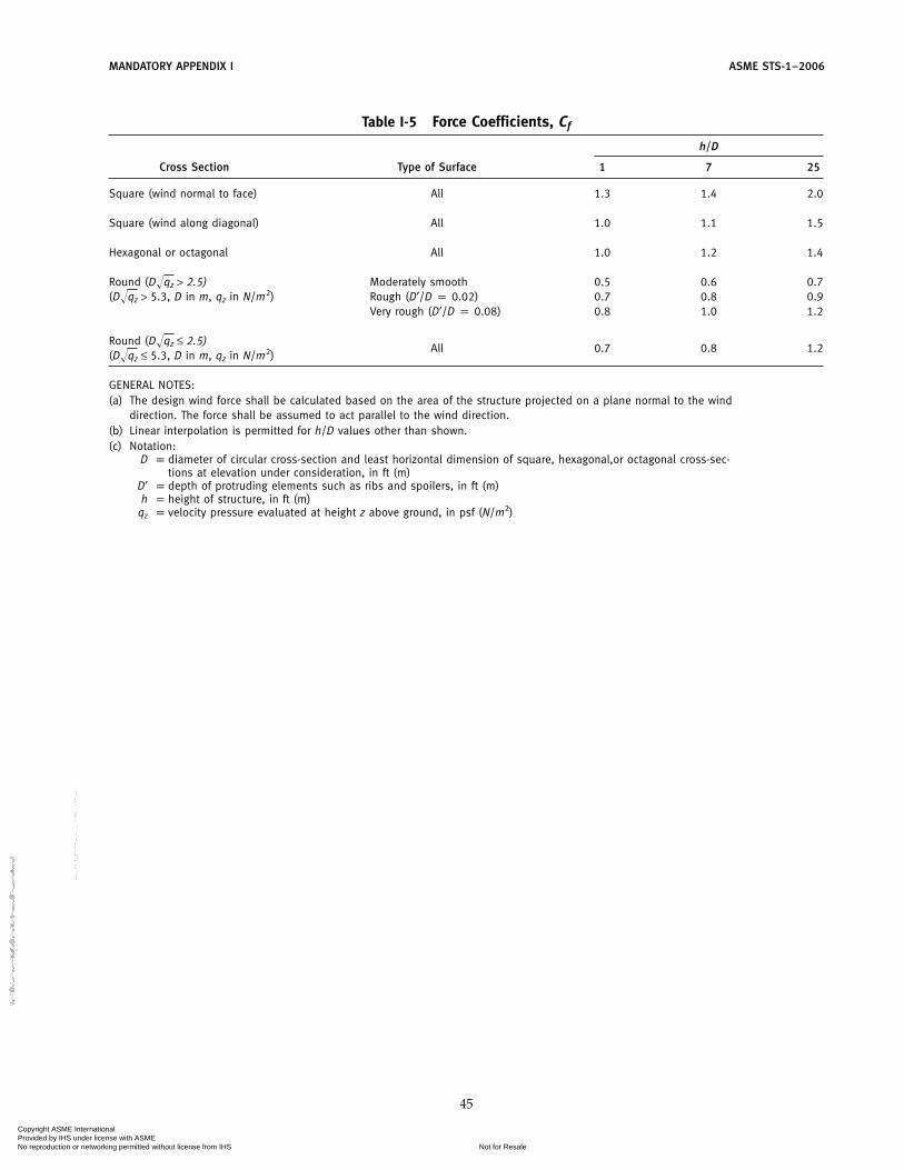
MANDATORY APPENDIX I ASME STS-1–2006
Table I-5 Force Coefficients, Cf
h/D
Cross Section Type of Surface 1 7 25
Square (wind normal to face) All 1.3 1.4 2.0
Square (wind along diagonal) All 1.0 1.1 1.5
Hexagonal or octagonal All 1.0 1.2 1.4
Round (D�qz > 2.5) Moderately smooth 0.5 0.6 0.7(D�qz > 5.3, D in m, qz in N/m2) Rough (D′/D p 0.02) 0.7 0.8 0.9
Very rough (D′/D p 0.08) 0.8 1.0 1.2
Round (D�qz ≤ 2.5)All 0.7 0.8 1.2
(D�qz ≤ 5.3, D in m, qz in N/m2)
GENERAL NOTES:(a) The design wind force shall be calculated based on the area of the structure projected on a plane normal to the wind
direction. The force shall be assumed to act parallel to the wind direction.(b) Linear interpolation is permitted for h/D values other than shown.(c) Notation:
D p diameter of circular cross-section and least horizontal dimension of square, hexagonal,or octagonal cross-sec-tions at elevation under consideration, in ft (m)
D′ p depth of protruding elements such as ribs and spoilers, in ft (m)h p height of structure, in ft (m)
qz p velocity pressure evaluated at height z above ground, in psf (N/m2)
45
Copyright ASME International Provided by IHS under license with ASME
Not for ResaleNo reproduction or networking permitted without license from IHS
--`,,```,,,,````-`-`,,`,,`,`,,`---
//^:^^#^~^^""~:@":^*^~$~"#:*~:*@
^:#^#:~~^^~:^":^@::~*\\

ASME STS-1–2006
NONMANDATORY APPENDIX AMECHANICAL DESIGN
0.030
0.025
0.020
0.015
20,000wTgDi
f = F
rict
ion
Fac
tor
0.0105
5
10
152025
2
2
NRe = Reynolds Number
NRe (approx.) =
Di = stack dia, ft
5 2 5105 106 107
Fig. A-1 Friction Factor f as Related to Reynolds Number and Stack Diameter
Table A-1 K Factors for Breeching EntranceAngle
K p factor depending on breeching entrance angle from verticalp 1.0 for 90 degp 0.75 for 60 degp 0.5 for 45 degp 0.2 for 30 degp 0.85 for 45 deg slope on top only
46
Copyright ASME International Provided by IHS under license with ASME
Not for ResaleNo reproduction or networking permitted without license from IHS
--`,,```,,,,````-`-`,,`,,`,`,,`---
//^:^^#^~^^""~:@":^*^~$~"#:*~:*@
^:#^#:~~^^~:^":^@::~*\\

NONMANDATORY APPENDIX A ASME STS-1–2006
50 mph
45 mph
40 mph
35 mph
30 mph
25 mph
20 mph
15 mph
10 mph
7 mph
5 mph
3 mph2 mph
600560520480440400360320
, Temperature Difference Between External Surfaceand Ambient Air Free Stream, �F
280240200160120804000.0
15141312111098Diameter, ft
Natural convection
Ambient Air Free Temperature: 60°F
Ext
ern
al H
eat
Tran
sfer
Co
effi
cien
t, B
tu/h
r-ft
2 –
�F
Forced convection
7654321
1.0
2.0
3.0
4.0
5.0
6.0
7.0
8.0
9.0
10.0
Fig. A-2 External Heat Transfer Coefficient for Forced and Natural Convection
47
Copyright ASME International Provided by IHS under license with ASME
Not for ResaleNo reproduction or networking permitted without license from IHS
--`,,```,,,,````-`-`,,`,,`,`,,`---
//^:^
^#^~
^^""
~:@
":^*^
~$~"
#:*~
:*@
^:#^
#:~~
^^~:
^":^
@::~
*\\

ASME STS-1–2006 NONMANDATORY APPENDIX A
1.2
1.1
1.0
0.9
0.8100
GENERAL NOTE: hT = (h60�F) (Temperature Correction Factor)T, where hT is the external heat transfer coefficient for forced convection when the ambient air free stream temperature is T (�F); h60�F is the external heat transfer coefficient for forced convection for a T (�F) of 60�F (see Fig. A-2).
Tem
per
atu
re C
orr
ecti
on
Fac
tor
90 80 70Ambient Air-Free Stream Temperature, T (�F)
60 50 40 30 20 10 0 −10
Fig. A-3 Effect of a Change in the Ambient Air Free Stream Temperature on the External Heat TransferCoefficient for Forced Convection
48
Copyright ASME International Provided by IHS under license with ASME
Not for ResaleNo reproduction or networking permitted without license from IHS
--`,,```,,,,````-`-`,,`,,`,`,,`---
//^:^^#^~^^""~:@":^*^~$~"#:*~:*@
^:#^#:~~^^~:^":^@::~*\\

NONMANDATORY APPENDIX A ASME STS-1–2006
Mean temperature = 300°F
Mean temperature = 400°F
Mean temperature = 200°F
4.2
4.0
3.8
3.4
3.6
3.2
3.0
2.8
2.6
2.4
2.2
2.0
1.8
1.6
1.4Hea
t Tra
nsf
er C
oef
fici
ent
for
Air
Gap
, Btu
/hr-
ft2
− °F
1.2
1.0
0.8
0.6
0.4
0.2
00 1 2 3
Air Gap, in.
4 5 6
∆T = 200°F∆T = 150°F∆T = 100°F∆T = 50°F∆T = 10°F
∆T = 200°F∆T = 150°F∆T = 100°F∆T = 50°F∆T = 10°F
∆T = 200°F∆T = 150°F∆T = 100°F∆T = 50°F∆T = 10°F
Fig. A-4 Heat Transfer Coefficient for the Air Gap Between Two Walls of a Double-Walled Metal Chimney
49
Copyright ASME International Provided by IHS under license with ASME
Not for ResaleNo reproduction or networking permitted without license from IHS
--`,,```,,,,````-`-`,,`,,`,`,,`---
//^:^^#^~^^""~:@":^*^~$~"#:*~:*@^:#^#:~~^^~:^":^@::~*\\

ASME STS-1–2006 NONMANDATORY APPENDIX A
Mean temperature = 600°F
8.0
7.8
7.6
7.2
7.4
7.0
6.8
6.6
6.4
6.2
6.0
5.8
5.6
5.4
Hea
t Tra
nsf
er C
oef
fici
ent
for
Air
Gap
, Btu
/hr-
ft2
− °F
4.8
5.0
5.2
4.6
4.4
4.2
4.00 1 2 3
Air Gap, in.
4 5 6
Mean temperature = 500°F
∆T = 200°F∆T = 150°F∆T = 100°F∆T = 50°F∆T = 10°F
∆T = 200°F∆T = 150°F∆T = 100°F∆T = 50°F∆T = 10°F
Fig. A-5 Heat Transfer Coefficient for the Air Gap Between Two Walls of a Double-Walled Metal Chimney
50
Copyright ASME International Provided by IHS under license with ASME
Not for ResaleNo reproduction or networking permitted without license from IHS
--`,,```,,,,````-`-`,,`,,`,`,,`---
//^:^^#^~^^""~:@":^*^~$~"#:*~:*@^:#^#:~~^^~:^":^@::~*\\

NONMANDATORY APPENDIX A ASME STS-1–2006
12.0
11.0
1 ft
2 ft
3 ft
4 ft
6 ft
8 ft
10 ft
12 ft
15 ft
Film temperature: 200°F
Internal diameterof cylindricalsmoke stack, ft
10.0
9.0
8.0
7.0
6.0
5.0
Inte
rnal
Hea
t Tra
nsf
er C
oef
fici
ent,
Btu
/hr-
ft2
− °F
3.0
4.0
2.0
1.0
0.00 10 20 30 40
Velocity, ft/sec
6050 70 80 90 100
Fig. A-6 Internal Heat Transfer Coefficient (Btu/hr-ft2°F) vs. Velocity (ft/sec) Film Temperature: 200°F
51
Copyright ASME International Provided by IHS under license with ASME
Not for ResaleNo reproduction or networking permitted without license from IHS
--`,,```,,,,````-`-`,,`,,`,`,,`---
//^:^^#^~^^""~:@":^*^~$~"#:*~:*@
^:#^#:~~^^~:^":^@::~*\\

ASME STS-1–2006 NONMANDATORY APPENDIX A
12.0
11.0
1 ft
2 ft
3 ft
4 ft
12 ft
6 ft
8 ft
10 ft
Film temperature: 300°F
Internal diameterof cylindricalsmoke stack, ft
10.0
9.0
8.0
7.0
6.0
5.0
Inte
rnal
Hea
t Tra
nsf
er C
oef
fici
ent,
Btu
/hr-
ft2
− °F
3.0
4.0
2.0
1.0
0.00 10 20 30 40
Velocity, ft/sec
6050 70 80 90 100
15 ft
Fig. A-7 Internal Heat Transfer Coefficient (Btu/hr-ft2°F) vs. Velocity (ft/sec) Film Temperature: 300°F
52
Copyright ASME International Provided by IHS under license with ASME
Not for ResaleNo reproduction or networking permitted without license from IHS
--`,,```,,,,````-`-`,,`,,`,`,,`---
//^:^
^#^~
^^""
~:@
":^*^
~$~"
#:*~
:*@
^:#^
#:~~
^^~:
^":^
@::~
*\\

NONMANDATORY APPENDIX A ASME STS-1–2006
12.0
11.0
1 ft
3 ft
2 ft
4 ft
12 ft
6 ft
8 ft
10 ft
Film temperature: 500°F
Internal diameterof cylindricalsmoke stack, ft
10.0
9.0
8.0
7.0
6.0
5.0
Inte
rnal
Hea
t Tra
nsf
er C
oef
fici
ent,
Btu
/hr-
ft2
− °F
3.0
4.0
2.0
1.0
0.00 10 20 30 40
Velocity, ft/sec
6050 70 80 90 100
15 ft
Fig. A-8 Internal Heat Transfer Coefficient (Btu/hr-ft2°F) vs. Velocity (ft/sec) Film Temperature: 500°F
53
Copyright ASME International Provided by IHS under license with ASME
Not for ResaleNo reproduction or networking permitted without license from IHS
--`,,```,,,,````-`-`,,`,,`,`,,`---
//^:^^#^~^^""~:@":^*^~$~"#:*~:*@
^:#^#:~~^^~:^":^@::~*\\

ASME STS-1–2006 NONMANDATORY APPENDIX A
12.0
11.0
1 ft
3 ft
2 ft
4 ft
12 ft
6 ft8 ft10 ft
Film temperature: 1000°F
Internal diameterof cylindricalsmoke stack, ft
10.0
9.0
8.0
7.0
6.0
5.0
Inte
rnal
Hea
t Tra
nsf
er C
oef
fici
ent,
Btu
/hr-
ft2 -
°F
3.0
4.0
2.0
1.0
0.00 10 20 30 40
Velocity, ft/sec
6050 70 80 90 100
15 ft
Fig. A-9 Internal Heat Transfer Coefficient (Btu/hr-ft2°F) vs. Velocity (ft/sec) Film Temperature: 1000°F
54
Copyright ASME International Provided by IHS under license with ASME
Not for ResaleNo reproduction or networking permitted without license from IHS
--`,,```,,,,````-`-`,,`,,`,`,,`---
//^:^^#^~^^""~:@":^*^~$~"#:*~:*@
^:#^#:~~^^~:^":^@::~*\\

NONMANDATORY APPENDIX A ASME STS-1–2006
1000
900
800
700
600
500
400
300
200
100
0 160
150
140
130
120
110
100
90
80
70
60
Example: Gas flow = 200,000 lb/hr; gas temp. = 500�F, gas velocity in flue = 50 ft/sec. Flue size = 70 ft.
50
40
30
20
10
0
W =
Gas
Flo
w 1
000
lb/h
r
Sta
ck D
ia. o
r Ex
it D
ia. (
in.)
[Not
e(1)
]
500F500F
300�F
400�F700�F
1000�F1200�F
60 ft
/sec
30 ft
/sec
45 ft
/sec
50 ft
/sec
72 ft
/sec
40 ft
/sec
80 ft
/sec
90 ft
/sec
Gas ve
locity V
S = 20 ft/
sec
900�F800�F600�F
500�FGas temp. TG = 200�F
1500�F1800�F
TG = 2300�F
NOTE:(1) For square or rectangular flues, use equal cross sectional areas.
Fig. A-10 Flue Size
55
Copyright ASME International Provided by IHS under license with ASME
Not for ResaleNo reproduction or networking permitted without license from IHS
--`,,```,,,,````-`-`,,`,,`,`,,`---
//^:^^#^~^^""~:@":^*^~$~"#:*~:*@
^:#^#:~~^^~:^":^@::~*\\

ASME STS-1–2006 NONMANDATORY APPENDIX A
100
200
300
400
500
600
700
800
900
1000
1100
1200
1300
1400
1500
1600
1700
1800
1900
2000
2100
Example: TAG = 600�F; H = 150 ft, 0 in.; TAMB = 60�F. Natural draft = 1.124 in.2.0
1.9
1.8
1.7
1.6
1.5
1.4
1.3
1.2
1.1
1.0
0.9
0.8
0.7
0.6
0.5
0.4
0.3
0.2
0.1
0.0
Ave
rage
Gas
Tem
p. T
AG
�F
Nat
ural
Dra
ft, i
n. o
f Wat
er
100100′–0–0″
60�F
0�F
–20�
F
Stack height = 20 ft, 0 in.
150 ft, 0 in.175 ft, 0 in.
275 ft, 0 in.
Am
bien
t tem
p. 1
00�–
0�80
�F
30�F
30 ft, 0 in.
40 ft, 0 in.50 ft, 0 in.60 ft, 0 in.70 ft, 0 in.
80 ft, 0 in.90 ft, 0 in.
100 ft, 0 in.
125 ft, 0 in.
200 ft, 0 in.225 ft, 0 in.
250 ft, 0 in.
300 ft, 0 in.350 ft, 0 in.
400 ft, 0 in.450 ft, 0 in.500 ft, 0 in.
Fig. A-11 Natural Draft
56
Copyright ASME International Provided by IHS under license with ASME
Not for ResaleNo reproduction or networking permitted without license from IHS
--`,,```,,,,````-`-`,,`,,`,`,,`---
//^:^^#^~^^""~:@":^*^~$~"#:*~:*@
^:#^#:~~^^~:^":^@::~*\\

NONMANDATORY APPENDIX A ASME STS-1–2006
0.00
0.20
0.10
0.11
0.40
0.50
0.60
0.30
Example: D = 5 ft, 0 in.; TAVG = 500�F; V = 50 ft/sec.Friction loss for 100 ft, �F = 0.11 (in. of water).
Gas velocity “V” (ft/sec)
10 20 30 40 50 60 700Fr
ictio
n Lo
ss, �
F (f
or 1
00 ft
) – in
. of W
ater
400�F
600�F
2100�F
600�
F
1200
�F
500�F
D = 15 ft, 0 in.
D = 5 ft, 0 in.
D = 2 ft, 0 in.
TAVG = 200�F
1500�F1200�F 1800�F
1000�F800�F
Gas velocity V = 20 ft/sec
V = 30 ft/sec
V = 40 ft/sec
V = 60 ft/sec
V = 50 ft/sec
D = 6 ft, 0 in.D = 7 ft, 0 in.
D = 10 ft, 0 in.
D = 15 ft, 0 in.
D = 20 ft, 0 in.D = 25 ft, 0 in.
Avg. g
as te
mp.
TAVG = 20
0�F
400�
F
800�
F
1000
�F
1500
�F
1800
�F21
00�F
500�
F
D = 4 ft, 0 in.
D = 3 ft, 0 in.
Flue dia. D = 2 ft, 0 in.
V = 70 ft/sec
D = 25 ft, 0 in.D = 20 ft, 0 in.
D = 10 ft, 0 in.
D = 5 ft, 0 in.
D = 8 ft, 0 in.
Fig. A-12 Friction Loss
57
Copyright ASME International Provided by IHS under license with ASME
Not for ResaleNo reproduction or networking permitted without license from IHS
--`,,```,,,,````-`-`,,`,,`,`,,`---
//^:^
^#^~
^^""
~:@
":^*^
~$~"
#:*~
:*@
^:#^
#:~~
^^~:
^":^
@::~
*\\

ASME STS-1–2006 NONMANDATORY APPENDIX A
0.00
10.0
20.0
30.0
40.0
50.0
60.0
70.0
80.0
90.0
100.0
Example: V = 80�/sec;T = 500�F; 10� exit cone; pressure drop �P 0.986�.
0.986�
2.85
3.00
2.55
2.70
2.10
1.95
2.40
2.25
1.80
1.50
1.20
1.05
0.90
0.60
0.75
0.45
0.15
0.30
0.00
1.35
1.65
V (G
as v
eloc
ity in
ft./s
ec)
�P (Pressure drop in in. of H
2 O)
2100
�F
1000
�F80
0�F
500�
F40
0�F
10 deg cone
15 deg cone
No cone 90 deg angle
60 deg angle
45 deg angle
30 deg angle entranceGas
tem
pera
ture
T =
200�
F
300�
F
600�
F
1200
�F
1500
�F18
00�F
Fig. A-13 Exit Loss and Entrance
58
Copyright ASME International Provided by IHS under license with ASME
Not for ResaleNo reproduction or networking permitted without license from IHS
--`,,```,,,,````-`-`,,`,,`,`,,`---
//^:^
^#^~
^^""
~:@
":^*^
~$~"
#:*~
:*@
^:#^
#:~~
^^~:
^":^
@::~
*\\

ASME STS-1–2006
NONMANDATORY APPENDIX BMATERIALS FOR AMBIENT AND ELEVATED TEMPERATURE
SERVICE
Table B-1 ASTM A 36 Carbon Steel
A – Chemical Composition of Elements
Elements Chemical Composition, %
Carbon 0.35 max.Manganese 0.29/1.06Phosphorus 0.048 max.Sulphur 0.058 max.Silicon 0.10 min.
B – Typical Annealed Properties
Temperature Minimum Yield Minimum Tensile Modulus of Elasticity
°F °C ksi MPa ksi MPa ksi MPa
−20 −29 36.0 248.0 58.0 399.6 29,676 204,471100 38 36.0 248.0 58.0 399.6 29,062 200,234150 66 33.8 232.9 58.0 399.6 28,831 198,644200 93 33.0 227.4 58.0 399.6 28,600 197,054250 121 32.4 223.2 58.0 399.6 28,350 195,332300 149 31.8 219.1 58.0 399.6 28,100 193,609400 204 30.8 212.2 58.0 399.6 27,700 190,853500 260 29.3 201.9 58.0 399.6 27,100 186,719600 316 27.6 190.2 58.0 399.6 26,400 181,896650 343 26.7 184.0 58.0 399.6 25,850 178,106700 371 25.8 177.8 58.0 399.6 25,300 174,317750 399 24.9 171.6 57.3 394.8 24,650 169,838800 427 24.1 166.0 53.3 367.2 24,000 165,360850 454 23.4 161.2 48.5 334.2 23,150 159,503900 482 22.8 157.1 43.3 298.3 22,300 153,647950 510 22.1 152.3 38.0 261.8 21,250 146,413
1000 538 21.4 147.4 33.4 230.1 20,200 139,178
GENERAL NOTES:(a) Properties taken from ASME Boiler and Pressure Vessel Code (BPVC), Section II.(b) Properties are “typical” unless otherwise indicated, and should not be taken as guaranteed properties.
59
Copyright ASME International Provided by IHS under license with ASME
Not for ResaleNo reproduction or networking permitted without license from IHS
--`,,```,,,,````-`-`,,`,,`,`,,`---
//^:^
^#^~
^^""
~:@
":^*^
~$~"
#:*~
:*@
^:#^
#:~~
^^~:
^":^
@::~
*\\

ASME STS-1–2006 NONMANDATORY APPENDIX B
Table B-2 ASTM A 387 GR 11 Alloy Steel
A – Chemical Composition of Elements
Elements Chemical Composition, %
Carbon 0.15 max.Manganese 0.30/0.61Phosphorus 0.045 max.Sulphur 0.045 max.Silicon 0.50 max.Chromium 0.80/1.25Molybdenum 0.44/0.65
B – Typical Annealed Properties (Class/Cond/Temper p 1)
Temperature Minimum Yield Minimum Tensile Modulus of Elasticity
°F °C ksi MPa ksi MPa ksi MPa
−20 −29 35.0 241.2 60.0 413.4 30,076 207,227100 38 35.0 241.2 60.0 413.4 29,462 202,990150 66 33.3 229.4 60.0 413.4 29,231 201,400200 93 32.3 222.5 60.0 413.4 29,000 199,810250 121 31.5 217.0 60.0 413.4 28,750 198,088300 149 30.7 211.5 60.0 413.4 28,500 196,365400 204 29.5 203.3 60.0 413.4 28,000 192,920500 260 28.4 195.7 60.0 413.4 27,400 188,786600 316 27.4 188.8 60.0 413.4 26,900 185,341650 343 26.9 185.3 60.0 413.4 26,550 182,929700 371 26.4 181.9 60.0 413.4 26,200 180,518750 399 25.9 178.5 60.0 413.4 25,900 178,451800 427 25.2 173.6 60.0 413.4 25,600 176,384850 454 24.5 168.8 58.3 401.7 25,200 173,628900 482 23.8 164.0 55.8 384.5 24,800 170,872950 510 22.9 157.8 52.6 362.4 24,350 167,771
1000 538 21.9 150.9 48.8 336.2 23,900 164,671
C – Typical Normalized and Tempered Properties (Class/Cond/Temper p 2)
Temperature Minimum Yield Minimum Tensile Modulus of Elasticity
°F °C ksi MPa ksi MPa ksi MPa
−20 −29 45.0 310.1 75.0 516.8 30,076 207,227100 38 45.0 310.1 75.0 516.8 29,462 202,990150 66 42.8 294.9 75.0 516.8 29,231 201,400200 93 41.5 285.9 75.0 516.8 29,000 199,810250 121 40.5 279.0 75.0 516.8 28,750 198,088300 149 39.5 272.2 75.0 516.8 28,500 196,365400 204 37.9 261.1 75.0 516.8 28,000 192,920500 260 36.5 251.5 75.0 516.8 27,400 188,786600 316 35.3 243.2 75.0 516.8 26,900 185,341650 343 34.6 238.4 75.0 516.8 26,550 182,929700 371 34.0 234.3 75.0 516.8 26,200 180,518750 399 33.2 228.7 75.0 516.8 25,900 178,451800 427 32.5 223.9 75.0 516.8 25,600 176,384850 454 31.6 217.7 72.8 501.6 25,200 173,628900 482 30.6 210.8 69.7 480.2 24,800 170,872950 510 29.4 202.6 65.7 452.7 24,350 167,771
1000 538 28.4 195.7 61.0 420.3 23,900 164,671
GENERAL NOTES:(a) Properties taken from ASME BPVC, Section II.(b) Properties are “typical” unless otherwise indicated, and should not be taken as guaranteed properties.
60
Copyright ASME International Provided by IHS under license with ASME
Not for ResaleNo reproduction or networking permitted without license from IHS
--`,,```,,,,````-`-`,,`,,`,`,,`---
//^:^
^#^~
^^""
~:@
":^*^
~$~"
#:*~
:*@
^:#^
#:~~
^^~:
^":^
@::~
*\\

NONMANDATORY APPENDIX B ASME STS-1–2006
Table B-3 ASTM A 387 GR 12 Alloy Steel
A – Chemical Composition of Elements
Elements Chemical Composition, %
Carbon 0.15 max.Manganese 0.30/0.61Phosphorus 0.045Sulphur 0.045 max.Silicon 0.50/1.00Chromium 1.00/1.50Molybdenum 0.44/0.65
B – Typical Annealed Properties (Class/Cond/Temper p 1)
Temperature Minimum Yield Minimum Tensile Modulus of Elasticity
°F °C ksi MPa ksi MPa ksi MPa
−20 −29 33.0 227.4 55.0 379.0 30,076 207,227100 38 33.0 227.4 55.0 379.0 29,462 202,990150 66 31.0 213.6 55.0 379.0 29,231 201,400200 93 29.8 205.3 54.0 372.1 29,000 199,810250 121 28.9 199.1 53.5 368.3 28,750 198,088300 149 28.1 193.6 52.9 364.5 28,500 196,365400 204 26.8 184.7 52.9 364.5 28,000 192,920500 260 25.9 178.5 52.9 364.5 27,400 188,786600 316 25.1 172.9 52.9 364.5 26,900 185,341650 343 24.8 170.9 52.9 364.5 26,550 182,929700 371 24.4 168.1 52.9 364.5 26,200 180,518750 399 24.0 165.4 52.9 364.5 25,900 178,451800 427 23.6 162.6 52.9 364.5 25,600 176,384850 454 23.1 159.2 52.9 364.5 25,200 173,628900 482 22.5 155.0 51.4 354.1 24,800 170,872950 510 21.7 149.5 48.9 336.9 24,350 167,771
1000 538 20.9 144.0 45.8 315.6 23,900 164,671
C – Typical Normalized and Tempered Properties (Class/Cond/Temper p 2)
Temperature Minimum Yield Minimum Tensile Modulus of Elasticity
°F °C ksi MPa ksi MPa ksi MPa
−20 −29 40.0 275.6 65.0 447.9 30,076 207,227100 38 40.0 275.6 63.8 439.6 29,462 202,990150 66 37.5 258.4 62.5 430.6 29,231 201,400200 93 36.2 249.4 62.5 430.6 29,000 199,810250 121 35.0 241.2 62.5 430.6 28,750 198,088300 149 34.0 234.3 62.5 430.6 28,500 196,365400 204 32.5 223.9 62.5 430.6 28,000 192,920500 260 31.4 216.3 62.5 430.6 27,400 188,786600 316 30.5 210.1 62.5 430.6 26,900 185,341650 343 30.1 207.4 62.5 430.6 26,550 182,929700 371 29.6 203.9 62.5 430.6 26,200 180,518750 399 29.1 200.5 62.5 430.6 25,900 178,451800 427 28.6 197.1 62.5 430.6 25,600 176,384850 454 28.0 192.9 62.5 430.6 25,200 173,628900 482 27.2 187.4 60.8 418.9 24,800 170,872950 510 26.3 181.2 57.8 398.2 24,350 167,771
1000 538 25.3 174.3 54.2 373.4 23,900 164,671
GENERAL NOTES:(a) Properties taken from ASME BPVC, Section II.(b) Properties are “typical” unless otherwise indicated, and should not be taken as guaranteed properties.
61
Copyright ASME International Provided by IHS under license with ASME
Not for ResaleNo reproduction or networking permitted without license from IHS
--`,,```,,,,````-`-`,,`,,`,`,,`---
//^:^^#^~^^""~:@":^*^~$~"#:*~:*@^:#^#:~~^^~:^":^@::~*\\

ASME STS-1–2006 NONMANDATORY APPENDIX B
Table B-4 ASTM A 242 Type 1/A 606 Type 4 (Corten A)
A – Chemical Composition of Elements
Elements Chemical Composition, %
Carbon 0.12 max.Manganese 0.20/0.50Phosphorus 0.07/0.15Sulphur 0.05 max.Silicon 0.25/0.75Copper 0.25/0.55Chromium 0.50/1.25Vanadium 0.65 max.
GENERAL NOTE: Reprinted with permission from USS Steels forElevated Temperature Service, 1976 revision.
B – Typical Tensile Properties
Temperature Minimum Yield Minimum Tensile Modulus of Elasticity
°F °C ksi MPa ksi MPa ksi MPa
−20 −29 54.1 372.7 81.3 560.2 30,000 206,70080 27 54.1 372.7 81.3 560.2 30,000 206,700
200 93 50.8 350.0 76.2 525.0 29,000 199,810400 204 47.6 328.0 76.4 526.4 28,000 192,920600 316 41.1 283.2 81.3 560.2 26,900 185,341800 427 39.9 274.9 76.4 526.4 25,600 176,384
1000 538 35.2 242.5 52.8 363.8 23,900 164,6711200 649 20.5 141.2 27.6 190.2 21,800 150,2021400 760 20.5 141.2 10.6 73.0 18,900 130,221
GENERAL NOTES:(a) Considerable deviation from the listed properties may occur as a result of the relatively broad chemical composition
range shown.(b) Properties are “typical” unless otherwise indicated, and should not be taken as guaranteed properties.(c) Values taken from “USS Steels for Elevated Temperature Service.”(d) Reprinted with permission from “USS Steels for Elevated Temperature Service,” 1976 revision.
62
Copyright ASME International Provided by IHS under license with ASME
Not for ResaleNo reproduction or networking permitted without license from IHS
--`,,```,,,,````-`-`,,`,,`,`,,`---
//^:^^#^~^^""~:@":^*^~$~"#:*~:*@^:#^#:~~^^~:^":^@::~*\\

NONMANDATORY APPENDIX B ASME STS-1–2006
Table B-5 ASTM A 588 GR A/A 709 (Corten B)
A – Chemical Composition of Elements
Elements Chemical Composition, %
Carbon 0.10/0.19Manganese 0.90/1.25Phosphorus 0.04 Max.Sulphur 0.05 Max.Silicon 0.15/0.30Copper 0.25/0.40Chromium 0.40/0.65Vanadium 0.02/0.10
GENERAL NOTE: Reprinted with permission from USS Steels forElevated Temperature Service, 1976 revision.
B – Typical Tensile Properties
Temperature Minimum Yield Minimum Tensile Modulus of Elasticity
°F °C ksi MPa ksi MPa ksi MPa
−20 −29 55.0 379.0 86.7 597.4 30,000 206,70080 27 55.0 379.0 86.7 597.4 30,000 206,700
200 93 51.7 356.2 81.4 560.8 29,000 199,810400 204 48.4 333.5 79.8 549.8 28,000 192,920600 316 46.7 321.8 75.5 520.2 26,900 185,341800 427 45.1 310.7 71.1 489.9 25,600 176,384
1000 538 35.8 246.7 52.0 358.3 23,900 164,6711200 649 20.0 137.8 30.3 208.8 21,800 150,2021400 760 9.4 64.8 11.3 77.9 18,900 130,221
GENERAL NOTES:(a) Considerable deviation from the listed properties may occur as a result of the relatively broad chemical composition
range shown.(b) This material should not be used above 800°F for load bearing structures because of possible loss of ductility.(c) Properties are “typical” unless otherwise indicated, and should not be taken as guaranteed properties.(d) Values taken from “USS Steels for Elevated Temperature Service.”(e) Reprinted with permission from “USS Steels for Elevated Temperature Service,” 1976 revision.
63
Copyright ASME International Provided by IHS under license with ASME
Not for ResaleNo reproduction or networking permitted without license from IHS
--`,,```,,,,````-`-`,,`,,`,`,,`---
//^:^^#^~^^""~:@":^*^~$~"#:*~:*@
^:#^#:~~^^~:^":^@::~*\\
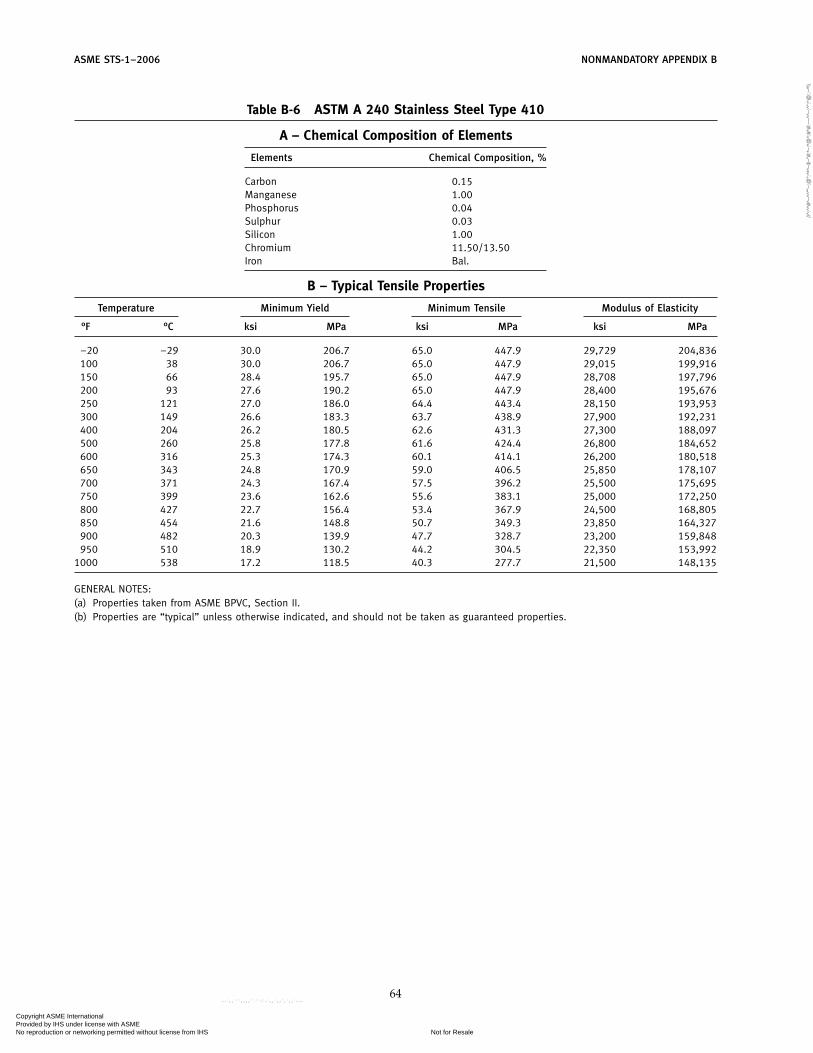
ASME STS-1–2006 NONMANDATORY APPENDIX B
Table B-6 ASTM A 240 Stainless Steel Type 410
A – Chemical Composition of Elements
Elements Chemical Composition, %
Carbon 0.15Manganese 1.00Phosphorus 0.04Sulphur 0.03Silicon 1.00Chromium 11.50/13.50Iron Bal.
B – Typical Tensile Properties
Temperature Minimum Yield Minimum Tensile Modulus of Elasticity
°F °C ksi MPa ksi MPa ksi MPa
−20 −29 30.0 206.7 65.0 447.9 29,729 204,836100 38 30.0 206.7 65.0 447.9 29,015 199,916150 66 28.4 195.7 65.0 447.9 28,708 197,796200 93 27.6 190.2 65.0 447.9 28,400 195,676250 121 27.0 186.0 64.4 443.4 28,150 193,953300 149 26.6 183.3 63.7 438.9 27,900 192,231400 204 26.2 180.5 62.6 431.3 27,300 188,097500 260 25.8 177.8 61.6 424.4 26,800 184,652600 316 25.3 174.3 60.1 414.1 26,200 180,518650 343 24.8 170.9 59.0 406.5 25,850 178,107700 371 24.3 167.4 57.5 396.2 25,500 175,695750 399 23.6 162.6 55.6 383.1 25,000 172,250800 427 22.7 156.4 53.4 367.9 24,500 168,805850 454 21.6 148.8 50.7 349.3 23,850 164,327900 482 20.3 139.9 47.7 328.7 23,200 159,848950 510 18.9 130.2 44.2 304.5 22,350 153,992
1000 538 17.2 118.5 40.3 277.7 21,500 148,135
GENERAL NOTES:(a) Properties taken from ASME BPVC, Section II.(b) Properties are “typical” unless otherwise indicated, and should not be taken as guaranteed properties.
64
Copyright ASME International Provided by IHS under license with ASME
Not for ResaleNo reproduction or networking permitted without license from IHS
--`,,```,,,,````-`-`,,`,,`,`,,`---
//^:^
^#^~
^^""
~:@
":^*^
~$~"
#:*~
:*@
^:#^
#:~~
^^~:
^":^
@::~
*\\

NONMANDATORY APPENDIX B ASME STS-1–2006
Table B-7 ASTM A 240 Stainless Steel Type 304
A – Chemical Composition of Elements
Elements Chemical Composition, %
Carbon 0.06Manganese 2.00Phosphorus 0.045Sulphur 0.030Silicon 0.75Chromium 18.0/12.00Nickel 8.0/10.5Iron Bal.
B – Typical Tensile Properties
Temperature Minimum Yield Minimum Tensile Modulus of Elasticity
°F °C ksi MPa ksi MPa ksi MPa
−20 −29 30.0 206.7 75.0 516.8 28,776 198,270100 38 30.0 206.7 75.0 516.8 28,115 193,715150 66 26.7 184.0 73.0 503.0 27,808 191,595200 93 25.0 172.3 71.0 489.2 27,500 189,475250 121 23.6 162.6 68.6 472.7 27,250 187,753300 149 22.4 154.3 66.2 456.1 27,000 186,030400 204 20.7 142.6 64.0 441.0 26,400 181,896500 260 19.4 133.7 63.4 436.8 25,900 178,451600 316 18.4 126.8 63.4 436.8 25,300 174,317650 343 18.0 124.0 63.4 436.8 25,050 172,594700 371 17.6 121.3 63.4 436.8 24,800 170,872750 399 17.2 118.5 63.4 436.8 24,450 168,461800 427 16.9 116.4 62.8 432.7 24,100 166,049850 454 16.5 113.7 62.0 427.2 23,800 163,982900 482 16.2 111.6 60.8 418.9 23,500 161,915950 510 15.9 109.6 59.3 408.6 23,150 159,503
1000 538 15.5 106.8 57.4 395.5 22,800 157,092
GENERAL NOTES:(a) Properties taken from ASME BPVC, Section II.(b) Properties are “typical” unless otherwise indicated, and should not be taken as guaranteed properties.
65
Copyright ASME International Provided by IHS under license with ASME
Not for ResaleNo reproduction or networking permitted without license from IHS
--`,,```,,,,````-`-`,,`,,`,`,,`---
//^:^
^#^~
^^""
~:@
":^*^
~$~"
#:*~
:*@
^:#^
#:~~
^^~:
^":^
@::~
*\\

ASME STS-1–2006 NONMANDATORY APPENDIX B
Table B-8 ASTM A 240 Stainless Steel Type 316
A – Chemical Composition of Elements
Elements Chemical Composition, %
Carbon 0.08Manganese 2.00Phosphorus 0.045Sulphur 0.030Silicon 0.75Chromium 16.0/18.00Nickel 10.0/14.0Iron Bal.
B – Typical Tensile Properties
Temperature Minimum Yield Minimum Tensile Modulus of Elasticity
°F °C ksi MPa ksi MPa ksi MPa
−20 −29 30.0 206.7 75.0 516.8 28,776 198,270100 38 30.0 206.7 75.0 516.8 28,115 193,715150 66 27.4 188.8 75.0 516.8 27,808 191,595200 93 25.9 178.5 75.0 516.8 27,500 189,475250 121 24.6 169.5 72.9 502.3 27,250 187,753300 149 23.4 161.2 71.9 495.4 27,000 186,030400 204 21.4 147.4 71.8 494.7 26,400 181,896500 260 20.0 137.8 71.8 494.7 25,900 178,451600 316 18.9 130.2 71.8 494.7 25,300 174,317650 343 18.5 127.5 71.8 494.7 25,050 172,594700 371 18.2 125.4 71.8 494.7 24,800 170,872750 399 17.9 123.3 71.5 492.6 24,450 168,461800 427 17.7 122.0 70.8 487.8 24,100 166,049850 454 17.5 120.6 69.7 480.2 23,800 163,982900 482 17.3 119.2 68.3 470.6 23,500 161,915950 510 17.1 117.8 66.5 458.2 23,150 159,503
1000 538 17.0 117.1 64.3 443.0 22,800 157,092
GENERAL NOTES:(a) Properties taken from ASME BPVC, Section II.(b) Properties are “typical” unless otherwise indicated, and should not be taken as guaranteed properties.
66
Copyright ASME International Provided by IHS under license with ASME
Not for ResaleNo reproduction or networking permitted without license from IHS
--`,,```,,,,````-`-`,,`,,`,`,,`---
//^:^
^#^~
^^""
~:@
":^*^
~$~"
#:*~
:*@
^:#^
#:~~
^^~:
^":^
@::~
*\\

NONMANDATORY APPENDIX B ASME STS-1–2006
Table B-9 ASTM A 240 Stainless Steel Type 304L
A – Chemical Composition of Elements
Elements Chemical Composition, %
Carbon 0.03Manganese 2.00Phosphorus 0.045Sulphur 0.030Silicon 0.75Chromium 18.0/20.00Nickel 8.0/12Iron Bal.
B – Typical Tensile Properties
Temperature Minimum Yield Minimum Tensile Modulus of Elasticity
°F °C ksi MPa ksi MPa ksi MPa
−20 −29 25.0 172.3 70.0 482.3 28,776 198,270100 38 25.0 172.3 70.0 482.3 28,115 193,715150 66 22.7 156.4 68.1 468.9 27,808 191,595200 93 21.4 147.4 66.1 455.4 27,500 189,475250 121 20.26 139.2 63.7 438.5 27,250 187,753300 149 19.2 132.3 61.2 421.7 27,000 186,030400 204 17.5 120.6 58.7 404.4 26,400 181,896500 260 16.4 113.0 57.5 396.2 25,900 178,451600 316 15.5 106.8 56.9 392.0 25,300 174,317650 343 15.2 104.7 56.7 390.7 25,050 172,594700 371 15.0 103.4 56.4 388.6 24,800 170,872750 399 14.7 101.3 56.0 385.8 24,450 168,461800 427 14.5 99.9 55.4 381.7 24,100 166,049850 454 14.3 98.5 54.6 376.2 23,800 163,982900 482 14.0 96.5 53.6 369.3 23,500 161,915950 510 13.7 94.4 52.3 360.3 23,150 159,503
1000 538 13.3 91.6 50.7 349.3 22,800 157,092
GENERAL NOTES:(a) Properties taken from ASME BPVC, Section II.(b) Properties are “typical” unless otherwise indicated, and should not be taken as guaranteed properties.
67
Copyright ASME International Provided by IHS under license with ASME
Not for ResaleNo reproduction or networking permitted without license from IHS
--`,,```,,,,````-`-`,,`,,`,`,,`---
//^:^^#^~^^""~:@":^*^~$~"#:*~:*@^:#^#:~~^^~:^":^@::~*\\

ASME STS-1–2006 NONMANDATORY APPENDIX B
Table B-10 ASTM A 240 Stainless Steel Type 316L
A – Chemical Composition of Elements
Elements Chemical Composition, %
Carbon 0.03Manganese 2.00Phosphorus 0.045Sulphur 0.030Silicon 0.75Chromium 16.0/18.00Nickel 10.0/14.0Iron Bal.
B – Typical Tensile Properties
Temperature Minimum Yield Minimum Tensile Modulus of Elasticity
°F °C ksi MPa ksi MPa ksi MPa
−20 −29 25.0 172.3 70.0 482.3 28,776 198,270100 38 25.0 172.3 70.0 482.3 28,115 193,715150 66 22.7 156.4 69.1 475.8 27,808 191,595200 93 21.3 146.8 68.1 469.2 27,500 189,475250 121 20.1 138.5 66.1 455.1 27,250 187,753300 149 19.0 130.9 64.0 441.0 27,000 186,030400 204 17.5 120.6 62.2 428.6 26,400 181,896500 260 16.4 113.0 61.8 425.8 25,900 178,451600 316 15.6 107.5 61.7 425.1 25,300 174,317650 343 15.3 105.4 61.6 424.4 25,050 172,594700 371 15.0 103.4 61.5 423.7 24,800 170,872750 399 14.7 101.3 61.1 421.0 24,450 168,461800 427 14.4 99.2 60.5 416.8 24,100 166,049850 454 14.1 97.1 59.7 411.3 23,800 163,982900 482 13.8 95.1 58.6 403.8 23,500 161,915950 510 13.5 93.0 57.1 393.4 23,150 159,503
1000 538 13.2 90.9 55.4 381.7 22,800 157,092
GENERAL NOTES:(a) Properties taken from ASME BPVC, Section II.(b) Properties are “typical” unless otherwise indicated, and should not be taken as guaranteed properties.
68
Copyright ASME International Provided by IHS under license with ASME
Not for ResaleNo reproduction or networking permitted without license from IHS
--`,,```,,,,````-`-`,,`,,`,`,,`---
//^:^^#^~^^""~:@":^*^~$~"#:*~:*@
^:#^#:~~^^~:^":^@::~*\\

NONMANDATORY APPENDIX B ASME STS-1–2006
Table B-11 ASTM A 240 Stainless Steel Type 317
A – Chemical Composition of Elements
Elements Chemical Composition, %
Carbon 0.08Manganese 2.00Phosphorus 0.045Sulphur 0.030Silicon 0.75Chromium 18.0/20.0Nickel 11.0/15.0Iron Bal.
B – Typical Tensile Properties
Temperature Minimum Yield Minimum Tensile Modulus of Elasticity
°F °C ksi MPa ksi MPa ksi MPa
−20 −29 30.0 206.7 75.0 516.8 28,776 198,270100 38 30.0 206.7 75.0 516.8 28,115 193,715150 66 27.4 188.8 75.0 516.8 27,808 191,595200 93 25.9 178.5 75.0 516.8 27,500 189,475250 121 24.6 169.5 72.9 502.3 27,250 187,753300 149 23.4 161.2 71.9 495.4 27,000 186,030400 204 21.4 147.4 71.8 494.7 26,400 181,896500 260 20.0 137.8 71.8 494.7 25,900 178,451600 316 18.9 130.2 71.8 494.7 25,300 174,317650 343 18.5 127.5 71.8 494.7 25,050 172,594700 371 18.2 125.4 71.8 494.7 24,800 170,872750 399 17.9 123.3 71.5 492.6 24,450 168,461800 427 17.7 122.0 70.8 487.8 24,100 166,049850 454 17.5 120.6 69.7 480.2 23,800 163,982900 482 17.3 119.2 68.3 470.6 23,500 161,915950 510 17.1 117.8 66.5 458.2 23,150 159,503
1000 538 17.0 117.1 64.3 443.0 22,800 157,092
GENERAL NOTES:(a) Properties taken from ASME BPVC, Section II.(b) Properties are “typical” unless otherwise indicated, and should not be taken as guaranteed properties.
69
Copyright ASME International Provided by IHS under license with ASME
Not for ResaleNo reproduction or networking permitted without license from IHS
--`,,```,,,,````-`-`,,`,,`,`,,`---
//^:^^#^~^^""~:@":^*^~$~"#:*~:*@
^:#^#:~~^^~:^":^@::~*\\

ASME STS-1–2006 NONMANDATORY APPENDIX B
Table B-12 ASTM A 516 Grade 70
A – Chemical Composition of Elements
Elements Chemical Composition, %
Carbon 0.28Manganese 0.85/1.20Phosphorus 0.035Sulphur 0.035Silicon 0.15/0.40
B – Typical Tensile Properties
Temperature Minimum Yield Minimum Tensile Modulus of Elasticity
°F °C ksi MPa ksi MPa ksi MPa
−20 −29 38.0 261.8 70.0 482.3 29,876 205,849100 38 38.0 261.8 70.0 482.3 29,262 201,612150 66 35.7 246.0 70.0 482.3 29,031 200,022200 93 34.8 239.8 70.0 482.3 28,800 198,432250 121 34.2 235.6 70.0 482.3 28,550 196,709300 149 33.6 231.5 70.0 482.3 28,300 194,987400 204 32.5 223.9 70.0 482.3 27,900 192,231500 260 31.0 213.6 70.0 482.3 27,300 188,097600 316 29.1 200.5 70.0 482.3 26,500 182,585650 343 28.2 194.3 70.0 482.3 26,000 179,140700 371 27.2 187.4 70.0 482.3 25,500 175,695750 399 26.3 181.2 69.1 476.1 24,850 171,217800 427 25.5 175.7 64.3 443.0 24,200 166,738850 454 24.7 170.2 58.6 403.8 23,350 160,882900 482 24.0 165.4 52.3 360.3 22,500 155,025950 510 23.3 160.5 45.9 316.3 21,450 147,791
1000 538 22.6 155.7 40.4 278.4 20,400 140,556
GENERAL NOTES:(a) Properties taken from ASME BPVC, Section II.(b) Properties are “typical” unless otherwise indicated, and should not be taken as guaranteed properties.
70
Copyright ASME International Provided by IHS under license with ASME
Not for ResaleNo reproduction or networking permitted without license from IHS
--`,,```,,,,````-`-`,,`,,`,`,,`---
//^:^
^#^~
^^""
~:@
":^*^
~$~"
#:*~
:*@
^:#^
#:~~
^^~:
^":^
@::~
*\\

NONMANDATORY APPENDIX B ASME STS-1–2006
Table B-13 ASTM A 240 Stainless Steel Type 309
A – Chemical Composition of Elements
Elements Chemical Composition, %
Carbon 0.08Manganese 2.00Phosphorus 0.045Sulphur 0.030Silicon 0.75Chromium 22/24Nickel 12/15Iron Bal.
B – Typical Tensile Properties
Temperature Minimum Yield Minimum Tensile Modulus of Elasticity
°F °C ksi MPa ksi MPa ksi MPa
−20 −29 30.0 206.7 75.0 516.8 28,776 198,270100 38 30.0 206.7 75.0 516.8 28,115 193,715150 66 27.6 190.2 75.0 516.8 27,808 191,595200 93 26.3 181.2 75.0 516.8 27,500 189,475250 121 25.1 172.9 74.9 515.7 27,250 187,753300 149 24.2 166.7 74.7 514.7 27,000 186,030400 204 22.7 156.4 73.2 504.0 26,400 181,896500 260 21.6 148.8 71.6 493.3 25,900 178,451600 316 20.8 143.3 70.2 483.7 25,300 174,317650 343 20.5 141.2 69.3 477.5 25,050 172,594700 371 20.2 139.2 68.3 470.6 24,800 170,872750 399 20.0 137.8 67.2 463.0 24,450 168,461800 427 19.7 135.7 65.8 453.4 24,100 166,049850 454 19.4 133.7 64.2 442.3 23,800 163,982900 482 19.1 131.6 62.5 430.6 23,500 161,915950 510 18.8 129.5 60.4 416.2 23,150 159,503
1000 538 18.4 126.8 58.2 401.0 22,800 157,092
GENERAL NOTES:(a) Properties taken from ASME BPVC, Section II.(b) Properties are “typical” unless otherwise indicated, and should not be taken as guaranteed properties.
71
Copyright ASME International Provided by IHS under license with ASME
Not for ResaleNo reproduction or networking permitted without license from IHS
--`,,```,,,,````-`-`,,`,,`,`,,`---
//^:^
^#^~
^^""
~:@
":^*^
~$~"
#:*~
:*@
^:#^
#:~~
^^~:
^":^
@::~
*\\

ASME STS-1–2006 NONMANDATORY APPENDIX B
Table B-14 ASTM A 240 Stainless Steel Type 310
A – Chemical Composition of Elements
Elements Chemical Composition, %
Carbon 0.08Manganese 2.00Phosphorus 0.045Sulphur 0.030Silicon 0.75Chromium 24/26Nickel 19/22Iron Bal.
B – Typical Tensile Properties
Temperature Minimum Yield Minimum Tensile Modulus of Elasticity
°F °C ksi MPa ksi MPa ksi MPa
−20 −29 30.0 206.7 75.0 516.8 28,776 198,270100 38 30.0 206.7 75.0 516.8 28,115 193,715150 66 27.9 192.2 74.6 514.0 27,808 191,595200 93 26.5 182.6 74.2 511.2 27,500 189,475250 121 25.3 174.3 72.5 499.5 27,250 187,753300 149 24.2 166.7 70.8 487.8 27,000 186,030400 204 22.6 155.7 69.6 479.5 26,400 181,896500 260 21.4 147.4 69.5 478.9 25,900 178,451600 316 20.6 141.9 69.5 478.9 25,300 174,317650 343 20.2 139.2 69.5 478.9 25,050 172,594700 371 19.9 137.1 69.3 477.5 24,800 170,872750 399 19.6 135.0 68.8 474.0 24,450 168,461800 427 19.4 133.7 68.0 468.5 24,100 166,049850 454 19.1 131.6 66.9 460.9 23,800 163,982900 482 18.8 129.5 65.5 451.3 23,500 161,915950 510 18.5 127.5 63.8 439.6 23,150 159,503
1000 538 18.2 125.4 61.6 424.4 22,800 157,092
GENERAL NOTES:(a) Properties taken from ASME BPVC, Section II.(b) Properties are “typical” unless otherwise indicated, and should not be taken as guaranteed properties.
72
Copyright ASME International Provided by IHS under license with ASME
Not for ResaleNo reproduction or networking permitted without license from IHS
--`,,```,,,,````-`-`,,`,,`,`,,`---
//^:^^#^~^^""~:@":^*^~$~"#:*~:*@
^:#^#:~~^^~:^":^@::~*\\
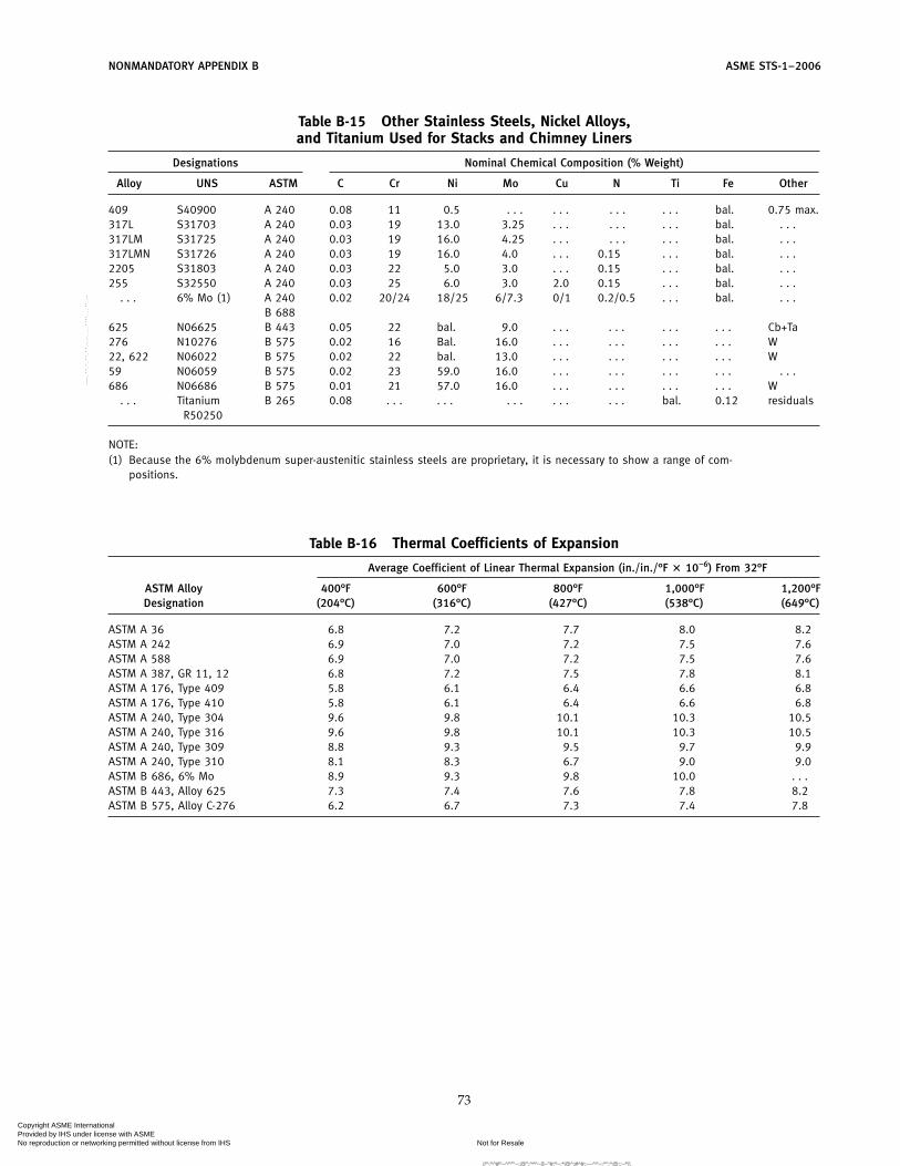
NONMANDATORY APPENDIX B ASME STS-1–2006
Table B-15 Other Stainless Steels, Nickel Alloys,and Titanium Used for Stacks and Chimney Liners
Designations Nominal Chemical Composition (% Weight)
Alloy UNS ASTM C Cr Ni Mo Cu N Ti Fe Other
409 S40900 A 240 0.08 11 0.5 . . . . . . . . . . . . bal. 0.75 max.317L S31703 A 240 0.03 19 13.0 3.25 . . . . . . . . . bal. . . .317LM S31725 A 240 0.03 19 16.0 4.25 . . . . . . . . . bal. . . .317LMN S31726 A 240 0.03 19 16.0 4.0 . . . 0.15 . . . bal. . . .2205 S31803 A 240 0.03 22 5.0 3.0 . . . 0.15 . . . bal. . . .255 S32550 A 240 0.03 25 6.0 3.0 2.0 0.15 . . . bal. . . .
. . . 6% Mo (1) A 240 0.02 20/24 18/25 6/7.3 0/1 0.2/0.5 . . . bal. . . .B 688
625 N06625 B 443 0.05 22 bal. 9.0 . . . . . . . . . . . . Cb+Ta276 N10276 B 575 0.02 16 Bal. 16.0 . . . . . . . . . . . . W22, 622 N06022 B 575 0.02 22 bal. 13.0 . . . . . . . . . . . . W59 N06059 B 575 0.02 23 59.0 16.0 . . . . . . . . . . . . . . .686 N06686 B 575 0.01 21 57.0 16.0 . . . . . . . . . . . . W
. . . Titanium B 265 0.08 . . . . . . . . . . . . . . . bal. 0.12 residualsR50250
NOTE:(1) Because the 6% molybdenum super-austenitic stainless steels are proprietary, it is necessary to show a range of com-
positions.
Table B-16 Thermal Coefficients of Expansion
Average Coefficient of Linear Thermal Expansion (in./in./°F � 10−6) From 32°F
ASTM Alloy 400°F 600°F 800°F 1,000°F 1,200°FDesignation (204°C) (316°C) (427°C) (538°C) (649°C)
ASTM A 36 6.8 7.2 7.7 8.0 8.2ASTM A 242 6.9 7.0 7.2 7.5 7.6ASTM A 588 6.9 7.0 7.2 7.5 7.6ASTM A 387, GR 11, 12 6.8 7.2 7.5 7.8 8.1ASTM A 176, Type 409 5.8 6.1 6.4 6.6 6.8ASTM A 176, Type 410 5.8 6.1 6.4 6.6 6.8ASTM A 240, Type 304 9.6 9.8 10.1 10.3 10.5ASTM A 240, Type 316 9.6 9.8 10.1 10.3 10.5ASTM A 240, Type 309 8.8 9.3 9.5 9.7 9.9ASTM A 240, Type 310 8.1 8.3 6.7 9.0 9.0ASTM B 686, 6% Mo 8.9 9.3 9.8 10.0 . . .ASTM B 443, Alloy 625 7.3 7.4 7.6 7.8 8.2ASTM B 575, Alloy C-276 6.2 6.7 7.3 7.4 7.8
73
Copyright ASME International Provided by IHS under license with ASME
Not for ResaleNo reproduction or networking permitted without license from IHS
--`,,```,,,,````-`-`,,`,,`,`,,`---
//^:^^#^~^^""~:@":^*^~$~"#:*~:*@^:#^#:~~^^~:^":^@::~*\\

ASME STS-1–2006 NONMANDATORY APPENDIX B
Table B-17 Maximum Nonscaling Temperature
ASTM Type or Grade Temp., Max.,[Note (1)] °F (°C)
A 36 800°F (427°C)A 242, Type 1 950°F (510°C)A 387, Gr. 11, 12 1,050°F (566°C)A 176, Type 409 1,300°F (704°C)A 176, Type 410 1,300°F (704°C)A 240, Type 304 1,650°F (899°C)A 240, Type 316 1,650°F (899°C)A 240, Type 317 1,650°F (899°C)A 240, Type 309 1,900°F (1 038°C)A 240, Type 310 2,000°F (1 038°C)
NOTE:(1) Manufacturers of types or grades not listed should be consulted
for recommendations.
74
Copyright ASME International Provided by IHS under license with ASME
Not for ResaleNo reproduction or networking permitted without license from IHS
--`,,```,,,,````-`-`,,`,,`,`,,`---
//^:^^#^~^^""~:@":^*^~$~"#:*~:*@
^:#^#:~~^^~:^":^@::~*\\

ASME STS-1–2006
NONMANDATORY APPENDIX CLININGS AND COATINGS
Table C-1 Suggested Suitability of Linings for Steel Stacks to Withstand Chemical andTemperature Environments of Flue Gases
LiningChemical Environment Thermal EnvironmentClassification
UNS No. Type (ASTM) Mild Moderate Severe Mild Moderate Severe
Organic Polyester X X . . . X . . . . . .Resin Novolac phenolic epoxy (1) X X X X X X (2)
Novolac epoxy (1) X X X X X . . .Epoxy X X . . . X . . . . . .Vinyl ester X X X X . . . . . .Urethanes X X . . . X . . . . . .
Organic Natural rubber X X . . . X . . . . . .Elastomers Neoprene X X . . . X . . . . . .
Chlorobutyl X X . . . X . . . . . .Fluoroelastomer X X X X X . . .
Inorganic Potassium Silicate X X X X X XMonolitic Calcium Aluminate X X . . . X X XConcrete Refractory X . . . . . . X X X
Insulating . . . . . . . . . X X X
Inorganic Borosilicate glass block X X X X X XMasonry Firebrick and refractory mortar X X . . . X X X
Acid resistant brick and chem- X X X X X Xically-resistant mortar
Insulating brick and refractory . . . . . . . . . X X Xmortar
UNS 40900 Stainless steel (A 240) (3) X . . . . . . X X XUNS 41000 Stainless steel (A 240) (3) X . . . . . . X X XUNS 30403 Stainless steel (A 240) (3) X X . . . X X XUNS S31603 Stainless steel (A 240) (3) X X . . . X X XUNS S31703 Stainless steel (A 240) X X . . . X X XUNS S31725 Stainless steel (A 240) X X . . . X X XUNS S31726 Stainless steel (A 240) X X . . . X X XUNS S31803 Stainless steel (A 240) X X X X X XUNS S32550 Stainless steel (A 240) X X X X X X6% Mo Stainless steel (A 240) X X X X X XUNS N06625 Nickel-based alloy (B 443) X X XX (4) X X XUNS N10276 Nickel-based alloy (B 575) X X XX (4) X X XUNS N06022 Nickel-based alloy (B 575) X X XX (4) X X XUNS N06059 Nickel-based alloy (B 575) X X XX (4) X X XUNS N06686 Nickel-based alloy (B 575) X X XX (4) X X XUNS R50250 Titanium (B 246) X X XX (4) X X X
GENERAL NOTE: Materials suppliers shall be consulted with respect to specific recommendations on usage.
NOTES:(1) Can be used in very severe chemical environments.(2) Coating may darken surface and convert to organic carbon at higher temperatures.(3) There is usually no significant price advantage to the use of these alloys as linings in place of solid alloys.(4) Most resistant of the alloys.
75
Copyright ASME International Provided by IHS under license with ASME
Not for ResaleNo reproduction or networking permitted without license from IHS
--`,,```,,,,````-`-`,,`,,`,`,,`---
//^:^^#^~^^""~:@":^*^~$~"#:*~:*@
^:#^#:~~^^~:^":^@::~*\\

ASME STS-1–2006 NONMANDATORY APPENDIX C
Table C-2 Suggested Stack Coating Characteristics and Classifications
GenericMaximum Cure
Type Mechanism Acid Salt Weather Dry Heat
Alkyd Air oxidation Poor Fair Excellent 250°F (121°C)
Chlorinated Solvent Excellent Excellent Good 150°F (66°C)rubber evaporation
Catalyzed Chemical Excellent Excellent Good 250°F–300°Fepoxy crosslinking (121°C–149°C)
Novolac phenolic Chemical Excellent Excellent Excellent 325°F (163°C)epoxy crosslinking
Novolac Chemical Excellent Excellent Excellent 250°F–300°Fepoxy crosslinking (121°C–149°C)
Aliphatic Chemical Very good Excellent Excellent 180°F–250°Fpolyurethane crosslinking (82°C–121°C)
Aluminum Solvent/heat Poor Good Good 1,000°F (538°C)silicone
Coal-tar Solvent Very good Excellent Poor 160°F–250°Fepoxy evaporation (71°C–121°C)
Vinyl Solvent Excellent Excellent Very good 150°F (66°C)evaporation
Inorganic Hydrolysis Excellent (1) Excellent Excellent 750°F–1,000°F (2)zinc (399°C–538°C)
Organic Chemical Very good (1) Very good Very good 300°F (149°C) (2)zinc-rich crosslinking
Inorganic Chemical Very good Excellent Excellent . . .silicate reaction
NOTES:(1) Indicated results based on primer being top coated.(2) Indicated results based on limitation of top coat in the system.
76
Copyright ASME International Provided by IHS under license with ASME
Not for ResaleNo reproduction or networking permitted without license from IHS
--`,,```,,,,````-`-`,,`,,`,`,,`---
//^:^
^#^~
^^""
~:@
":^*^
~$~"
#:*~
:*@
^:#^
#:~~
^^~:
^":^
@::~
*\\

NONMANDATORY APPENDIX C ASME STS-1–2006
1000
100
10120 130 140 150 160
9010−5
10−4
10−3
100 110 120 130 140
a. 10% H2O from oilb. 6% H2O from coal
a. 10% H2O from oilb. 6% H2O from coal
6% H2O b. a. 10% H2O by volume
b. 6% H2O a. 10% H2O by volume
1500.1
1
10
170 180
Su
lfu
r Tri
oxid
e in
Gas
, pp
m
Su
lfu
r Tri
oxid
e in
Gas
, pp
m
Su
lfu
r Tri
oxid
e in
Gas
, Vo
lum
e %
Su
lfu
r Tri
oxid
e in
Gas
, Vo
lum
e %
(356°F) (374°F)(338°F)(320°F)(302°F)(284°F)
Dewpoint Versus Sulfur Trioxide Concentration
Dewpoint, °C
Dewpoint, °C
(266°F)(248°F)
190
10−1
10−2
10−3
Fig. C-1 Dewpoint in Stack Gases
77
Copyright ASME International Provided by IHS under license with ASME
Not for ResaleNo reproduction or networking permitted without license from IHS
--`,,```,,,,````-`-`,,`,,`,`,,`---
//^:^
^#^~
^^""
~:@
":^*^
~$~"
#:*~
:*@
^:#^
#:~~
^^~:
^":^
@::~
*\\
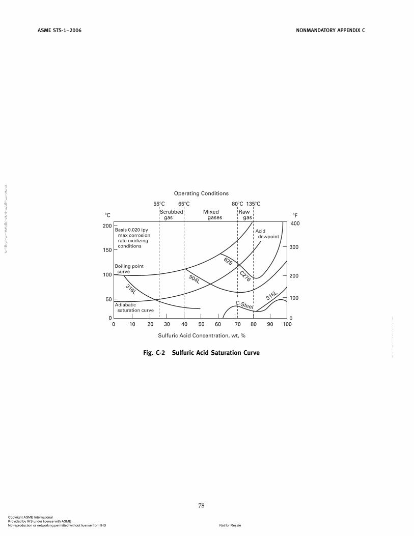
ASME STS-1–2006 NONMANDATORY APPENDIX C
300
�F400
Operating Conditions
200
316L
904L
625
C276
316L
C-Steel
�C
150
Basis 0.020 ipy max corrosion rate oxidizing conditions
55�C 65�C 80�CScrubbed gas
Mixed gases
Raw gas
Acid dewpoint
135�C
Boiling point curve
100
50
0
200
1009080706050
Sulfuric Acid Concentration, wt, %
403020100
100
0
Adiabatic saturation curve
Fig. C-2 Sulfuric Acid Saturation Curve
78
Copyright ASME International Provided by IHS under license with ASME
Not for ResaleNo reproduction or networking permitted without license from IHS
--`,,```,,,,````-`-`,,`,,`,`,,`---
//^:^^#^~^^""~:@":^*^~$~"#:*~:*@
^:#^#:~~^^~:^":^@::~*\\

ASME STS-1–2006
NONMANDATORY APPENDIX DSTRUCTURAL DESIGN
60402010
Frequency, cps.
Velo
cit
y, in
./sec
86420.80.60.40.2 10.11
2
4
6
8
10
20
40
60
80
100
200
400
600
800
1000
1000
800
600
400
200
100
8060
40
20
108
6
4
2
10.8
00.6
00.4
0
0.20
0.10
0.0800.80
2
4
68
10
20
40
60
80
100
200
400
600
800
1000
2000
4000Accele
ratio
n, %Displacem
ent, in.
6000
8000
10,000
0.600.40
0.20
0.100.0800.0600.040
0.020
0.0100.0080.0060.004
0.060
0.040
0.020
0.010
0.008
00.0
060
0.004
0
0.002
0
0.001
00.0
008
80 100 200 400 600 800 1000
0.0006
0.0004
Fig. D-1 Normalized Response Spectrum Values
79
Copyright ASME International Provided by IHS under license with ASME
Not for ResaleNo reproduction or networking permitted without license from IHS
--`,,```,,,,````-`-`,,`,,`,`,,`---
//^:^^#^~^^""~:@":^*^~$~"#:*~:*@^:#^#:~~^^~:^":^@::~*\\

ASME STS-1–2006 NONMANDATORY APPENDIX D
Table D-1 Special Values for Maximum GroundAcceleration of 1.0g
VelocityFrequency, Displacement Spectrum, Acceleration
Hz Spectrum, in. in./sec Spectrum, g
f ≤ 0.25 50.7 318.6f 5.186f 2
0.25 ≤ f ≤ 2.510.39
f 1.1436
65.26
f 0.14361.062f 0.8564
2.5 ≤ f ≤ 925.32
f 2.1158
159.1
f 1.1158
2.589
f 0.1158
9 ≤ f ≤ 3363.87
f 2.5369
401.3
f 1.5369
6.533
f 0.5369
f > 339.768
f 2
61.37f
1.00
80
Copyright ASME International Provided by IHS under license with ASME
Not for ResaleNo reproduction or networking permitted without license from IHS
--`,,```,,,,````-`-`,,`,,`,`,,`---
//^:^^#^~^^""~:@":^*^~$~"#:*~:*@
^:#^#:~~^^~:^":^@::~*\\

NONMANDATORY APPENDIX D ASME STS-1–2006
Honolulu
Maui
Hawaii
Molokai
Av = 0.30
Av = 0.30
Av = 0.20
St. Thomas
0 100 200 300
St. Croix
Vieques
St. JohnCulebra
Av = 0.20
0.300.40
0.300.200.150.100.
05
0 90
0.15
0.15
0.15
0.40
0.40
0.40
0.400.40
0.20
0.200.20
0.05
0.10
0.10
Kauai
Guam Tutuila
0.10
0.10
0.10
0.100.10
0.200.20
0.11
0.12
0.05
0.05
0.15
0.15
0.15
0.10
0.20
0.20
0.400.05
0.05
0.30
0.21
0.05
0.10
0.10
0.15
0.15
0.20
0.30
0.30
0.400.30
0.40
0.40
Fig. D-2 Seismic Zone Map
81
Copyright ASME International Provided by IHS under license with ASME
Not for ResaleNo reproduction or networking permitted without license from IHS
--`,,```,,,,````-`-`,,`,,`,`,,`---
//^:^^#^~^^""~:@":^*^~$~"#:*~:*@^:#^#:~~^^~:^":^@::~*\\

ASME STS-1–2006 NONMANDATORY APPENDIX D
Table D-2 Response Spectrum Scaling RatioVersus Av
Av, Effective PeakVelocity-Related
Accelerations Scaling Ratio
0.05 0.040.08 0.060.15 0.110.20 0.150.30 0.230.40 0.30
GENERAL NOTE: Linear interpolation may be used in between Av
coefficients not given.
82
Copyright ASME International Provided by IHS under license with ASME
Not for ResaleNo reproduction or networking permitted without license from IHS
--`,,```,,,,````-`-`,,`,,`,`,,`---
//^:^
^#^~
^^""
~:@
":^*^
~$~"
#:*~
:*@
^:#^
#:~~
^^~:
^":^
@::~
*\\

NONMANDATORY APPENDIX D ASME STS-1–2006
0.10
0.10
0.10
0.10
0.08
0.05
0.05
0.11
0.11
0.05
0.05
0.11
0.10
0.10 0.05 0.11
0.10 0.10
0.100.10
0.33
0 100
Miles
200 300
0.15
0.20
0.05
Fig. D-2a Seismic Zone Map
83
Copyright ASME International Provided by IHS under license with ASME
Not for ResaleNo reproduction or networking permitted without license from IHS
--`,,```,,,,````-`-`,,`,,`,`,,`---
//^:^
^#^~
^^""
~:@
":^*^
~$~"
#:*~
:*@
^:#^
#:~~
^^~:
^":^
@::~
*\\

ASME STS-1–2006 NONMANDATORY APPENDIX D
Table D-3 Allowable Creep Stress of Carbon Steel at Elevated Temperature
Allowable Creep Stresses (in ksi) (1)
Temperature (°F)
Type of Steel (2) 750 800 850 900 950 1000 1050 1100
A 36 (5) 14.3 (3) ‡ · · · · · ·A 53 Gr B (5) 10.3 (3)
A 242 Type I ·· 12-17 8-13 5-9 ‡ ‡ · ·(6)(8)A 618 Gr 1 (6)(8)
A 588 Gr A (6)(8) ·· 12-17 ‡ ‡ ‡ ‡ · ·A 588 Gr B (6) 8-13 5-9
A 387 Gr 11 (7) ·· ·· ·· 15.7 (3) 10.7 (3) 7.1 (4) 4.4 (4) 2.7 (4)A 335 Gr P11 (7)
A 387 Gr 12 (7) ·· ·· ·· 18.0 (3) 11.3 (3) 7.3 (3) 4.5 (4) 2.5 (4)A 335 Gr P12 (7)
·· Indicates that the creep value does not govern—normal allowable stresses based on Fy govern.· Indicates that the use of this steel is not recommended at this temperature.‡ Indicates that the use of this steel at this temperature is only recommended for noncritical
applications.
NOTES:(1) The values presented in this Table are allowable stresses based on the criteria presented in para. 3.3.5 with a design
life of 100,000 hr. The appropriated factor of safety has been incorporated in these values.(2) Creep and rupture properties are highly dependent upon the exact chemical composition of the steel. The values indi-
cated in the table are intended to be used only as a reference. Values used in design should be obtained from testdata reflecting the precise chemical composition of the steel to be used in the ductwork fabrication.
(3) The allowable stress value at this temperature is governed by the creep rupture strength.(4) The allowable stress value at this temperature is governed by the creep rate.(5) Creep and rupture properties for this steel are derived from ASTM DS-11S1.(6) Creep and rupture properties for this steel are derived from various United States Steel Corporation publications, includ-
ing Steels for Elevated Temperature Service.(7) Creep and rupture properties for this steel are derived from ASTM DS-50. These values differ from some of the ASME
values because ASME limits the allowable stress to 0.25 Fy, which is a limitation for boilers, not ducts.(8) A range of values is presented for A 242, A 588, and A 618 steels because of the potentially large variation in chemis-
try, which can drastically affect the steel’s properties. The lower bound value should be used unless data indicateotherwise.
Table D-4 Creep and Rupture Properties of Type 410 Stainless Steel
Stress for a Creep Rate of Stress for Rupture in
0.0001% per hr 0.00001% per hrTest Temperature 1% in 10,000 hr 1% in 100,000 hr 1,000 hr 10,000 hr
°F °C ksi MPa ksi MPa ksi MPa ksi MPa
900 482 24 165 13.6 94 34 234 22 1521000 538 9 62 7.4 51 19.4 134 13 901100 593 4.2 29 3.6 25 10 69 6.8 471200 649 2 14 1.7 12 4.8 33 2.8 191300 704 0.8 6 0.8 4 2.5 17 1.2 81400 760 . . . . . . . . . . . . 1.2 8 0.6 4
84
Copyright ASME International Provided by IHS under license with ASME
Not for ResaleNo reproduction or networking permitted without license from IHS
--`,,```,,,,````-`-`,,`,,`,`,,`---
//^:^
^#^~
^^""
~:@
":^*^
~$~"
#:*~
:*@
^:#^
#:~~
^^~:
^":^
@::~
*\\

NONMANDATORY APPENDIX D ASME STS-1–2006
Table D-5 Creep and Rupture Properties of Type 304 Stainless Steel
Stress for a Creep Rate of Stress for Rupture in
0.0001% per hr 0.00001% per hrTest Temperature 1% in 10,000 hr 1% in 100,000 hr 1,000 hr 10,000 hr
°F °C ksi MPa ksi MPa ksi MPa ksi MPa
1000 538 25.5 176 17.9 123 49.8 343 36 2481100 593 16.5 114 11.1 77 31 214 22.2 1531200 649 10.8 74 7.2 50 19 131 13.8 951300 704 7 48 4.5 31 11.9 82 8.5 591400 760 4.6 32 2.9 20 7.7 53 5.3 371500 816 3 21 1.8 12 4.7 32 3.3 23
Table D-6 Creep and Rupture Properties of Type 316 Stainless Steel
Stress for a Creep Rate of Stress for Rupture in
0.0001% per hr 0.00001% per hrTest Temperature 1% in 10,000 hr 1% in 100,000 hr 1,000 hr 10,000 hr
°F °C ksi MPa ksi MPa ksi MPa ksi MPa
1000 538 35.5 245 20.1 139 50 345 43 2961100 593 22.5 155 12.4 85 34 234 26.5 1831200 649 14.2 98 7.9 54 23 159 16.2 1121300 704 8.9 61 4.8 33 15.4 106 9.9 661400 760 5.6 39 3 21 10.3 71 6 411500 816 3.6 25 1.9 13 6.7 46 3.7 26
Table D-7 Creep and Rupture Properties of Type 317 Stainless Steel
Stress for a Creep Rate of Stress for Rupture in
0.0001% per hr 0.00001% per hrTest Temperature 1% in 10,000 hr 1% in 100,000 hr 1,000 hr 10,000 hr
°F °C ksi MPa ksi MPa ksi MPa ksi MPa
1000 538 24 165 16 110 . . . . . . . . . . . .1100 593 17.3 119 14.7 101 34 234 28 1931200 649 12.7 88 8.7 60 24 165 13.3 921300 704 7.3 50 4.7 32 16.7 115 10.7 741400 760 4.3 30 2.3 16 10.3 71 6.7 461500 816 2.7 19 2 14 6.7 46 3.3 23
85
Copyright ASME International Provided by IHS under license with ASME
Not for ResaleNo reproduction or networking permitted without license from IHS
--`,,```,,,,````-`-`,,`,,`,`,,`---
//^:^^#^~^^""~:@":^*^~$~"#:*~:*@
^:#^#:~~^^~:^":^@::~*\\

ASME STS-1–2006
NONMANDATORY APPENDIX EEXAMPLE CALCULATIONS
Example Calculation E-1: Velocity Pressure (qz)
Stack 1 Stack 2 Stack 3
3-sec gust speed V 90 100 110 mphImportance factor I 1.00 1.00 1.00 (unitless)
Stack height h 80.00 160.00 240.00 ftTop outside diameter D 5.000 10.000 15.000 ft
Exposure category C C C C Input ValuesFirst mode frequency �1 2.60 1.30 0.90 Hz
Plate thickness t 0.250 0.3125 0.375 in.Damping value � 0.006 0.006 0.006 (unitless)
Slenderness ratio h/D 16.0 16.0 16.0Force coefficient cf 0.65 0.65 0.65 Table I-5
Gust effect factor Gf 0.95 1.01 1.05 See Mandatory Calculated ValuesAppendix I
Topographical factor Kzt 1.000 1.000 1.000 Eq. (4-5)Exposure coefficient Kz (at h) 1.210 1.390 1.516 Table 1-4
Velocity pressure qz (at h) 25.09 35.58 46.96 psf
86
Copyright ASME International Provided by IHS under license with ASME
Not for ResaleNo reproduction or networking permitted without license from IHS
--`,,```,,,,````-`-`,,`,,`,`,,`---
//^:^
^#^~
^^""
~:@
":^*^
~$~"
#:*~
:*@
^:#^
#:~~
^^~:
^":^
@::~
*\\

NONMANDATORY APPENDIX E ASME STS-1–2006
Example Calculation E-2: Gust Effect Factor (Gf)
Gf p 0.925 �1 + 1.7Iz �g2QQ2 + g2
R2R2
1 + 1.7Iz gv �Stack 1 Stack 2 Stack 3
3-sec gust speed V 90 100 110 mphImportance factor I 1.00 1.00 1.00 (unitless)
Stack height h 80.00 160.00 240.00 ftTop outside diameter D 5.000 10.000 15.000 ft
Exposure category C C C . . .First mode frequency �1 2.60 1.30 0.90 Hz
Plate thickness t 0.250 0.3125 0.375 in.Damping value � 0.006 0.006 0.006 (unitless)
Stack width B 5.000 10.000 15.000 ftTurbulence intensity factor c 0.20 0.20 0.20 Table I-1Integral length scale factor l 500 500 500 ft (Table I-1)
Integral length scale power law exponent 0.2 0.2 0.2 Table I-1Equivalent height z 48.00 96.00 144.00 ft
Intensity turbulence Iz 0.188 0.167 0.156 . . .Integral length scale of turbulence Lz 538.91 619.04 671.34 ft
Background response Q 0.914 0.884 0.863 . . .Mean hourly wind speed factor b 0.65 0.65 0.65 Table I-1
Mean hourly wind speed law exponent a 0.154 0.154 0.154 Table I-1Mean hourly wind speed Vz 90.89 112.35 131.55 . . .
Reduced frequency N1 15.42 7.16 4.59 . . .. . . Rn 0.0245 0.0403 0.0535 . . .. . . �h 10.53 8.52 7.55 . . .. . . �b 0.658 0.532 0.472 . . .. . . �d 2.20 1.78 1.58 . . .. . . Rh 0.0905 0.1105 0.1236 . . .. . . RB 0.6747 0.7226 0.7475 . . .. . . Rd 0.3522 0.4082 0.4410 . . .
Resonant Response Factor R 0.4160 0.6221 0.7794 . . .Peak Factor of Resonant Response gR 4.411 4.252 4.164 . . .
Peak Factor for Wind Response gv 3.4 3.4 3.4 . . .Peak Factor for Background Response gQ 3.4 3.4 3.4 . . .
Gust Effect Factor Gf 0.95 1.01 1.05 (unitless)
Example Calculation E-3: Along Wind Loads
Wind design based upon ASCE 7, as applicable forsteel stack design used as an Example of the designmethod for ASME STS-1.
3 Second Gust Velocity (mph) V p 100(Fig. 1-1, Mandatory Appendix I)
Stack Height (ft) h p 140
Stack Diameter - Top 1⁄3 (ft) d p 8
Importance Factor (unitless) I p 1.00(Table I-3 and Table I-2)
87
Exposure Category CSection 4.3.3.4
Zmin. (ft) Zmin. p 15(Table I-1)
c (unitless) c p 0.20(Table I-1)
Equivalent Structure Height (ft)(Mandatory Appendix I)z p 0.6, h p 84
Intensity of Turbulence (unitless) Iz(Mandatory Appendix I)
Copyright ASME International Provided by IHS under license with ASME
Not for ResaleNo reproduction or networking permitted without license from IHS
--`,,```,,,,````-`-`,,`,,`,`,,`---
//^:^^#^~^^""~:@":^*^~$~"#:*~:*@
^:#^#:~~^^~:^":^@::~*\\

ASME STS-1–2006 NONMANDATORY APPENDIX E
Iz p c �33z �
1/6
p 0.1712
Topographical Factors K1, K2, K3 (Fig. 1-2)K1 p 0.00K2 p 1.00K3 p 1.00
Combined Topographic Factor K21[eq. (4.5)]Ku p (1 + K1 K2 K3)2 p 1.0000
Velocity Pressure Exposure Coeff.Per Table 1-4, pg. 46 Kz (at h) p 1.360
Velocity Pressure qz (at h), [eq. (4.4)]qz p 0.00256 Kz, Kz V2l p 34.816 (psf)
Force Coefficient Cf (at h), (Table I-5)for (h/D) p 17.50
Cr p 0.6583
Terrain Exposure Constants , b, �, l(Table I-1)
p 0.2000 (unitless)b p 0.65 (unitless)� p 0.1538 (unitless)l p 500 (ft)
Stack First Mode Natural Frequency (Hz) n1(Modal Frequency Analysis)n1 p 1.335
Gust Factor Calculation GfMandatory Appendix I)
Integral Scale Length (ft) LzLz p l (z/33) p 602.73037
Factors gQ and gv (unitless)gQ p 3.4gv p 3.4
Background Response Q (unitless)
Q p� 1
1 + 0.63 �B + hLz �
0.63p 0.8908
Mean Hourly Wind Speed Vz (ft/sec)
Vz p b � z33�
u
V �2215� p 110.0703
Coefficient N1 (unitless)
N1 pniLi
Vip 7.3103
88
Coefficient �h, �b, �d (unitless)�h p 4.6n1h/Vz p 7.8108�b p 4.6n1B/Vz p 0.4463�d p 15.4n1d/Vz p 1.4942
Coefficient gR (unitless)
gR p �2 In (3600n1) +0.577
�2 In �3600n1p 4.2578
Coefficient Rn (unitless)
Rn p7.47 N1
�1 + 10.3N1 53
p 0.0397
Coefficients Rh, RB, Rd (unitless)Rh p Rt setting � p �hRB p Rt setting � p �bRd p Rt setting � p �d
Ri p1�
−1
2 �2(1 − e−2�) for � > 0
1 for � p 0Rh p 0.1198RB p 0.7586Rd p 0.4566
Mass per unit length of top 1⁄3 of stack ma (lbm/ft)Para. 5.2.1.(b), pg. 22ma p 319.0
Air Density � (lbm/ft3)� p 0.076474
Avg. Stack Diameter top 1⁄3 D (ft)D p 8.0000
Aerodynamic Damping �a (unitless)[eq. (5.1)]
�a pCf � D V z4 �mani
p 0.008284
Structural Damping �r (unitless)(Table 5.1)�r p 0.004
Total Damping � (unitless)� p �a + �r p 0.012284
Resonance Response Factor R (unitless)
R p �1�
RnRhRg (0.53 + 0.47 Rd) p 0.4680
Gust Factor Gr (unitless)
Gf p 0.925 �l + 1.7 Iz �gq2 Q2 + gR
2 R2
1 + 1.7 Iz gv � p 0.9555
Copyright ASME International Provided by IHS under license with ASME
Not for ResaleNo reproduction or networking permitted without license from IHS
--`,,```,,,,````-`-`,,`,,`,`,,`---
//^:^^#^~^^""~:@":^*^~$~"#:*~:*@
^:#^#:~~^^~:^":^@::~*\\

NONMANDATORY APPENDIX E ASME STS-1–2006
Table E-1 Stack Along Wind Loading
Velocity Velocity Base Fluctuating BaseElevation, Pressure Pressure, Force Mean Load Moment, Load, Moment,
Location, z, Coefficient, qz i, Coefficient, w(z) i, Mo (i to i+1), WD(z) i, M* (i to i+1),i ft Kz i psf Ct i lbt/ft kip-ft lbt/ft kip-ft
1 140 1.360 34.816 0.6583 84.7340 . . . 122.4351 . . .2 130 1.335 34.176 0.6583 83.1764 113.3525 113.6897 159.45713 120 1.310 33.536 0.6583 81.6188 103.0100 96.1990 115.7303
4 110 1.285 32.896 0.6583 80.0612 92.9790 113.6897 115.73035 100 1.260 32.256 0.6583 78.5036 83.2595 87.4536 96.49056 90 1.240 31.744 0.6583 77.2575 73.9969 78.7083 76.9998
7 80 1.210 30.976 0.6583 75.3884 64.8901 69.9629 63.25818 70 1.170 29.952 0.6583 72.8962 55.6275 61.2175 49.26559 60 1.130 28.928 0.6583 70.4040 46.5933 52.4722 37.0220
10 50 1.090 27.904 0.6583 67.9118 38.0576 43.7268 26.527611 40 1.040 26.624 0.6583 64.7966 29.8854 34.9815 17.782212 30 0.980 25.088 0.6583 61.0583 22.0558 26.2361 10.7859
13 20 0.900 23.04 0.6583 56.0740 14.6831 17.4907 5.538714 10 0.850 21.76 0.6583 52.9588 8.2034 8.7454 2.040615 0 0.850 21.76 0.6583 52.9588 2.6479 0.0000 0.2915
Mo p 749.2419 M* p 799.9092
Total Base Moment M p Mo + M* p 1549.15 kip-ft
GENERAL NOTE: A linear variation in load between the calculation points is assumed in calculation of the moments.
Example Calculation E-4: Earthquake Response
For a lumped mass system, such as shown in Example1, the response spectra analysis is as follows:
(a) The displacement ujn of the jth mass in the nthmode of vibration is given by
ujn p �nuonarn (1)
where�n p participation factor of the nth mode
n p
N
j p 1Mjajn
N
j p 1Mja
2jn
(2)
N p number of massesMj p the jth mass of stackuo
n p design response spectra value for the nthmode frequency
ajn p the nth mode shape value of the jth mass
For the horizontal excitation, the bending momentMin and shear force Vin at the ith mass location and inthe nth mode of vibration can be obtained, as
89
Vin p N
j p 1Mj�
2nujn (3)
Min p N
j p 1Mj�
2nujn(hj − hi) (4)
(b) The overturning moment is
MA,n p N
j p 1(Mj�
2nujnhj) + IA�2
n�A,n (5)
where� p natural circular frequency of the nth mode
of stack, in radians per secondIA p mass moment of inertia of footing about
point A�A,n p the nth mode rotation of footing of stack
In the general case, when a stack is supported at manyplaces, the shear forces Vin and bending moments Minalong a stack can be obtained by static analysis due toinertia loads
Fj p Mj�2nujn , j p 1 to N (6)
Copyright ASME International Provided by IHS under license with ASME
Not for ResaleNo reproduction or networking permitted without license from IHS
--`,,```,,,,````-`-`,,`,,`,`,,`---
//^:^^#^~^^""~:@":^*^~$~"#:*~:*@^:#^#:~~^^~:^":^@::~*\\

ASME STS-1–2006 NONMANDATORY APPENDIX E
Total shear force Vi and bending moments Mi at theith location are calculated from the modal values Vinand Min using expressions
Vi p � N
n p 1V2
in�1⁄2
(7)
Mi p � N
n p 1M2
in�1⁄2
(8)
whereN p number of governing modes, i.e., modes which
contribute 10% or more to the responses.
90
Copyright ASME International Provided by IHS under license with ASME
Not for ResaleNo reproduction or networking permitted without license from IHS
--`,,```,,,,````-`-`,,`,,`,`,,`---
//^:^
^#^~
^^""
~:@
":^*^
~$~"
#:*~
:*@
^:#^
#:~~
^^~:
^":^
@::~
*\\

NONMANDATORY APPENDIX E ASME STS-1–2006
Example Calculation E-5: Earthquake Response Spectrum ExampleA single-wall steel stack, which has a height of 210 ft, outside diameter of 12 ft, and thickness of 0.50 in., which is located
with Av p 0.30 has the following modal properties and response spectrum earthquake SRSS values.
Modal Properties
1 2 3 4 5
Frequency (cycle/sec) 0.883 5.373 14.429 26.740 41.371Time period (sec) 1.132 0.186 0.069 0.037 0.024Participation factor 1.6008 −0.9801 0.4572 −0.414 0.2089Scaled displacement (ft) 0.2994 0.018 0.0018 0.0004 0.0001
Mode Shape, ft:
Elev (ft) 1 2 3 4 5 SRSS
210 1.0000 1.0000 1.0000 1.0000 1.0000 0.4796196 0.9087 0.6833 0.4818 0.2706 0.0541 0.4357182 0.8175 0.3695 −0.0118 −0.3630 −0.6344 0.3919168 0.7266 0.0699 −0.4099 −0.6960 −0.6823 0.3483154 0.6367 −0.2009 −0.6437 −0.6201 −0.1261 0.3052140 0.5485 −0.4279 −0.6734 −0.2032 0.5582 0.2630126 0.4629 −0.5979 −0.5039 0.3311 0.8113 0.2221112 0.3808 −0.7016 −0.1867 0.7080 0.4251 0.1829
98 0.3033 −0.7353 0.1921 0.7344 −0.2956 0.146084 0.2317 −0.7017 0.5333 0.3929 −0.7776 0.111870 0.1673 −0.6101 0.7507 −0.1517 −0.6350 0.080956 0.1113 −0.4762 0.7944 −0.6366 0.0249 0.054042 0.0652 −0.3213 0.6656 −0.8358 0.6915 0.031828 0.0303 −0.1712 0.4192 −0.6794 0.8665 0.014814 0.0081 −0.0541 0.1550 −0.3020 0.4816 0.0040
0 0.0000 0.0000 0.0000 0.0000 0.0000 0.0000
Moment, ft-kips:
Elev (ft) 1 2 3 4 5 SRSS
210 0 0 0 0 0 0196 72 2661 19186 65894 157732 62182 274 8958 56860 167448 332516 213168 594 17222 94081 221161 307182 426154 1019 25858 115574 183151 66594 677140 1535 33425 112369 63421 −213779 948126 2130 38715 83326 −83092 −318044 1231112 2791 40823 34947 −185969 −166383 1521
98 3507 39197 −20594 −195537 119371 181984 4267 33658 −68763 −108314 311865 213170 5060 24384 −96467 30687 259070 246556 5877 11863 −95364 149693 5951 282642 6710 −3191 −63777 184799 −239327 321728 7553 −19956 −6651 109762 −266473 363714 8400 −37632 66561 −54813 −20266 4081
GENERAL NOTE: Shear calculation method similar with base shear p 37 kips.
E-5 VORTEX SHEDDING DESIGN(THIS METHODOLOGY IS NOT AN EXAMPLE)
NOTE: This subsection does not apply to guyed or braced stacks(Sections 4.10 and 4.11).
The steel stack response to vortex-induced wind loadsis based upon dimensions, modal properties for thevibration mode being considered, the structural damp-ing, �s and aerodynamic damping, �a.
It should be noted that the structural damping forvortex shedding is in accordance with para. 5.2(b). This
91
is not the same value of damping used for seismic loads.Response is highly sensitive to small changes in
damping �s where values of A2 are near 1.
GENERAL THEORY
The root-mean-square motion at the point of maxi-mum displacement is given by
aM
Dp
C1CM
mr � �(�s + �a)1⁄2
Copyright ASME International Provided by IHS under license with ASME
Not for ResaleNo reproduction or networking permitted without license from IHS
--`,,```,,,,````-`-`,,`,,`,`,,`---
//^:^^#^~^^""~:@":^*^~$~"#:*~:*@
^:#^#:~~^^~:^":^@::~*\\

ASME STS-1–2006 NONMANDATORY APPENDIX E
�a p −C2
mr �1 − 4�aM
D �2�� p H ⁄D
mr p me ��D 2g
me p �H
0m(z) �2 (z)dz��
H
0�2 (z)dz
C2 p 0.6 (for parallel stacks only)
CM p �(zM)�1H
�H
0�2 (z)dz�
1⁄2
1H �
H
0
�2(z)dz
�(zM) p Value of �(z) at maximum deflectionzM p H for cantilever mode
CM p 2.0 for the fundamental mode of vibrationC1 p 0.12 for an isolated steel stack
C1 p0.12(5S)2
� for a grouped steel stack
For a group of two or more identical steel stacks,the amplification factor � and Strouhal Number S aregiven as,
� p 1.50 −(A�D − 3)
24, 3 <
A
D< 15
� p 1.0 forA
D≥ 15
S p 0.16 +1
300 � A
D− 3� for
A
D< 15
S p 0.20 forA
D≥ 15
ForAD
< 3 or for groups of identical steel stacks ornonidentical steel stack groups, interference effects shallbe established by reference to model test, or other studiesof similar arrangements.
E-6 COMPUTATION OF VORTEX-INDUCED RESPONSE(THIS METHODOLOGY IS NOT AN EXAMPLE)
Evaluation of Loads Due to Vortex Shedding
The equation defining aM�D can be written as,aM
Dp
A1
1 − A2�1 − 4�aM
D �2� �1⁄2
A1 p C1 CM�mr ��s �
A2 p C2�mr �s
For mr �s > 0.8aM
Dp
A1
�1 − � C2
mr �S��1⁄2
92
For mr �s < 0.4aM
Dp 0.5 �1 −
mr �s
C2 �1⁄2
Practical Application
The general solution may be reduced to the followingformulas of vortex shedding and then used to determineequivalent static loads. For any values of mr �s,
aM p D �− (1 − A2) + �(1 − A2)2 + 16 A12A2
8 A2 �1⁄2
The peak values for vortex shedding response are:
a p g aM and as p gs aM
where a is the maximum value and is used to calculatepeak loads and stresses while as defines equivalent con-stant amplitude for fatigue calculations. The values ofg and gs are determined from the following:
For mr �s > 0.8,g p 4.0
gs p 2.0
For mr �s < 0.4,g p 1.6
gs p 1.5
Linear interpolation is used for 0.4 < mr �s < 0.8.
Equivalent Static Loads
The equivalent static loads corresponding the dis-placement, aM, are given by:
w(z) p a (2�n1) 2 � (z) m(z)⁄gc
ws(z) p as (2�n1)2 � (z) m(z)⁄gc
The number of cycles in T years at the equivalentconstant amplitude as is given by:
N⁄n1 p � T50� 1010 �Vc�I
Vzcr �2
exp � − 15�Vc�IVzcr �
2
�Vc and Vzcr
are evaluated at the same height.
A fatigue analysis can be performed using the methodsin the CICIND Model Code for Steel Chimneys or theAmerican Institute of Steel Construction (AISC).
Variable Diameter Stacks
For variable diameter stacks, the preceding method maybe used with the following modifications to account forthe range of possible critical diameters. The previousmethod is used with the following changes in formulas.
Copyright ASME International Provided by IHS under license with ASME
Not for ResaleNo reproduction or networking permitted without license from IHS
--`,,```,,,,````-`-`,,`,,`,`,,`---
//^:^
^#^~
^^""
~:@
":^*^
~$~"
#:*~
:*@
^:#^
#:~~
^^~:
^":^
@::~
*\\

NONMANDATORY APPENDIX E ASME STS-1–2006
The peak response is determined by varying the rangeof height being considered for any mean diameter, Dfor a portion of the steel stack where the diameter varies15% from this mean diameter. The peak response isdetermined by iterations over the full height of the stack.
CM p � (zM)
� 1H �
z2
z1
�2 (z)dz �1⁄2
1H �
H
0
�2 (z) dz
R p
� �z2
z1
�2 (z)dz ��H
0
�2 (z) dz
R p 1.0 for nearly parallelC2 p 0.6 R
The limits change to
mr �s > 0.8 Rmr �s < 0.4 R
Symbols and Definitions
A p center-to-center stack spacing for interfer-ence effects, ft
A1 p constantA2 p constant
a p maximum value amplitude for staticequivalent design loads, ft
as p maximum value amplitude for staticequivalent fatigue loads, ft
aM p r. m. s. dynamic displacement at zpzm, ftC1 p constant for grouped/isolated stacksC2 p constant
CM p mode shape constantD p mean diameter for the segment z1 to z2, or
for stacks with less than ±10% variationover the top 1⁄3 the value of D is the averageover the top 1⁄3, ft
H p height of steel stack, ftg p constant for maximum static equiv. loadsg p gravitational acceleration (32.2 ft/sec2)
gc p gravitational constant (32.2 lbm-ft/lbf-sec2)
gs p constant for fatigue static equiv. loadsme p equivalent uniform mass per unit length,
lbm/ftm(z) p mass per unit length at height z, lbm/ft
mr p dimensionless massn1 p natural frequency of mode, Hz
NT p effective number of cycles in period yearsR p constant for tapered stacks
93
S p Strouhal numberT p life of stack in years
Vc p critical speed for the segmentz1 to z2 p 5n1D, ft/sec
Vzcrp mean hourly design speed (50-year return
period) at the critical height zcr used forevaluating the critical wind velocity (ft/sec)
z p height z under consideration, ftzcr p 1⁄2 (z1 + z2) or, for stacks with less than
±10% variation over the top third, zcr p 5⁄6H, ft
zM p height at maximum modal shape displace-ment (H for mode 1), ft
z1, z2 p upper and lower limits of a section of thestack over which the diameter changes by30% (i.e., D ±15%), ft
a p amplification factor�a p aerodynamic damping�s p structural damping� p aspect ratio� p air density (0.00238), lbm-sec2/ft4
�(z) p normalized mode shape at height, z(unitless)
�(zM) p max normalized modal displacement �(z)for mode at z p zM, for the first modez p H (unitless)
�(z) p equivalent static load, lbf/ft�s(z) p equivalent fatigue load, lbf/ft
E-7 VORTEX SHEDDING EXAMPLE(EXAMPLE CALCULATION)
Vortex Shedding Design per E-5 for steel stacks withless than 10% variation in diameter in the upper 1⁄3 ofthe stack. Stack is 140 ft tall, 8 ft diameter and 0.3125in. constant wall thickness.
Height (ft):H p 140.00 ft
Top 1⁄3 Ht Mean OS Diameter, ft:D p 8.00
Top 1⁄3 Ht Mean Thickness, in.:t p 0.3125 in.
3-sec gust Velocity (mph) from (Fig. I-1)V p 100
Importance Factor (Table I-2 and Table I-3)Ifactor p 1.00
Reference Design Wind Speed:
VR p V �l factor
Exposure: (para. 4.3.3.4): C
Copyright ASME International Provided by IHS under license with ASME
Not for ResaleNo reproduction or networking permitted without license from IHS
--`,,```,,,,````-`-`,,`,,`,`,,`---
//^:^^#^~^^""~:@":^*^~$~"#:*~:*@
^:#^#:~~^^~:^":^@::~*\\

ASME STS-1–2006 NONMANDATORY APPENDIX E
First Mode Frequency, Hz:n1 p 1.335
Density of air, slugs/ft3:� p 0.00238
Gravity Constant, ft/sec2
g p 32.2
Structural Damping, unlined (Table 5-1):�s p 0.004
Shape Factor (Table I-5):Cf p 0.6583
Spacing between stacks:A p 160 ft (20 � D)
First Mode, therefore (E-5):CM p 2.0
Strouhal Number (E-5):
St p if �AD
> 15, 0.2, 0.16 +1
300 �AD − 3��Average Diameter for Top 1⁄3 Ht:
Dbar p DDbar p 8 ft
St p 0.20
Vortex Shedding Elevation Range:z1 p Hz2 p 0
For Exposure C (Table 4A-1):
�bar p1
6.5bbar p 0.65
c p 0.2Ift p 500
p15
Number of Sections:n p 15k p 1...nI p 500
Zmin p 15� p 9.5zg p 900
94
Zk odk htk mk (lbn/
k (ft) EIk (ft) (ft) (ft) ft) �k
1 140 135 8 10 320 1.0000
2 130 125 8 10 320 0.9022
3 120 115 8 10 320 0.8044
4 110 105 8 10 320 0.7072
5 100 95 8 10 320 0.6113
6 90 85 8 10 320 0.5176
7 80 75 8 10 320 0.4272
8 70 65 8 10 320 0.3413
9 60 55 8 10 320 0.2616
10 50 45 8 10 320 0.1894
11 40 35 8 10 320 0.1263
12 30 25 8 10 320 0.0742
13 20 15 8 10 320 0.0346
14 10 5 8 10 320 0.0092
15 0 0 8 0 0 0.0000
Critical Elevation
zcr p56
H
zcr p 116.67 ftz1 p 140.00 ftz2 p 0.00 ft
Critical Velocity
Vc p1St
n1 Dbar
Vc p 53.40 fps
Vc3044
p 36.41 mph
Mean Hourly Design Speed at 5H/6 (ft):
Vz.cr p bbar �zcr
33��
barVR
4430
Vz.cr p 115.78 fps
If Vc > 1.2 * Vzcr then ignoreRegion p if (Vc > 1.2 Vzcr,
“Need not Consider”, “Consider”)Region p “Consider”
If Vc > 1.2 Vzcr but less than 1.2 * Vzcr reduction factorallowed:
Freduction p �Vzcr
Vc �2
Reduction p if (Vc > Vzcr, “true”, “false”)Reduction p “false”
Freduction p if (Reduction p “true”, Freduction, 1)Freduction p 1.00
Grouped Chimney effects must be considered below15 � Spa:
A p 160.00
Copyright ASME International Provided by IHS under license with ASME
Not for ResaleNo reproduction or networking permitted without license from IHS
--`,,```,,,,````-`-`,,`,,`,`,,`---
//^:^^#^~^^""~:@":^*^~$~"#:*~:*@
^:#^#:~~^^~:^":^@::~*\\

NONMANDATORY APPENDIX E ASME STS-1–2006
For Spacing below 3 � Spa/D.bar Seek Advice:
Advice p if � ADbar
< 3, ”Seek Advice”, “Use Code”��gp1 p 1.0
�gp2 p 1.5 −124 � A
Dbar− 4�
�gp2 p 0.83Advice p “Use Code”
�gp3 p 2.0�gr p if �A > 15 Dbar, 1, if (A ≥
4 Dbar, �gp2, �gp3)��gr p 1.00
� pH
Dbar� p 17.50
C1 p0.12
(5 St)2�gr C1 p 0.12
�c p 15
k p 1(�k)2 htk �c p 35.288
me p1�c
15
k p 1mk htk (�k)2 me p 320.000 lbm/ft
Max. Deflection at Top for 1st Mode:�zM p 1.0
C2 p 0.60
CMt p
�zM �1H
�c�1⁄2
1H
�c
CMt p 1.992
mr pme
� Dbar2 g
mr p 65.24
mr �s p 0.2610
A1 pC1 CM
mr ��s �A1 p 0.01390
A2 p0.60
mr �sA2 p 2.30
mr p �s p 0.2610me �s
� g Dbar2
p 0.2610
For any value of mr * �s:
am p Dbar �-1 (1 − A2) + �(1 − A2)2 + 16 A12 A2
8 A2 �1⁄2
am p 3.01
gxh p 1.6 +(mr �
s− 0.4) 2.4
0.4gxh p 0.766
gxs p 1.5 +(mr �
s− 0.4) 0.5
0.4gxs p 1.326
95
ghat p if �mr �s < 0.4, 1.6, �if (mr �s >
0.8, 4.0, gxh���ghat p 1.60
ghat p if �mr �s < 0.4, 1.5, �if (mr �s >
0.8, 2.0, gxh���gs p 1.50
For Peak Loads:ah p ghat am ah p 4.8134
For Fatigue:as p gs am as p 4.5125
whkp �ah (2 � n1)2 �k mk�
wskp �as (2 � n1)2 �k mk�
whk
wsk
k zk (ft) (lb/ft) (lb/ft)
1.00 140.00 3366 31552.00 130.00 3036 28473.00 120.00 2707 25384.00 110.00 2380 22315.00 100.00 2057 19296.00 90.00 1742 16337.00 80.00 1438 13488.00 70.00 1149 10779.00 60.00 880 825
10.00 50.00 637 59811.00 40.00 425 39912.00 30.00 250 23413.00 20.00 116 10914.00 10.00 31 2915.00 0.00 0 0
Peak Bending Moment for Vortex Shedding:
Mh p1
1000 g 15
k p 2 �whk
+ whk − 1
2 � (zk − 1 − zk)(zk + zk−1)
2
Mh p 18784 ft-Kip
Avg. Peak Moment to Consider for Fatigue:
Ms p1
1000 g 15
k p 2 �wsk
+ wsk − 1
2 � (zk − 1 − zk)(zk + zk−1)
2
Ms p 17,610 ft-kip
Copyright ASME International Provided by IHS under license with ASME
Not for ResaleNo reproduction or networking permitted without license from IHS
--`,,```,,,,````-`-`,,`,,`,`,,`---
//^:^
^#^~
^^""
~:@
":^*^
~$~"
#:*~
:*@
^:#^
#:~~
^^~:
^":^
@::~
*\\

ASME STS-1–2006 NONMANDATORY APPENDIX E
Number of Stresses at Peak Moment for Fatigue:
NT p � T50� n1 1010 �Vc �lfactor
Vz cr �2
exp �-15�Vc �lfactor
Vz cr �2�
Nf 0 p 1.17 � 108 cycles (based on 50 years)
Calculate Bending Stress due to Peak Moment forfatigue consideration.
Section Modulus:D p 8.00 ft
96
Din. p D −t6
S p�
32 D(D4 − Din.
4) 123
S p 2239.95 in.3
�b pMs 12
S�b p 94.34 ksi
High bending stress level indicates failure for thisstack configuration. Additional damping or aerody-namic wind spoilers such as helical strakes arerequired.
Copyright ASME International Provided by IHS under license with ASME
Not for ResaleNo reproduction or networking permitted without license from IHS
--`,,```,,,,````-`-`,,`,,`,`,,`---
//^:^^#^~^^""~:@":^*^~$~"#:*~:*@^:#^#:~~^^~:^":^@::~*\\

ASME STS-1–2006
NONMANDATORY APPENDIX FCONVERSION FACTORS: U.S. CUSTOMARY TO SI (METRIC)
Table F-1 Length
To Convert From To Multiply By
in. mm 25.4in. cm 2.54ft m 0.3048yd m 0.9144
mile (statute) km 1.609
Table F-2 Area
To Convert From To Multiply By
sq in. mm2 645.16sq in. cm2 6.451sq ft m2 0.0929
sq in. m2 0.0006451sq yd m2 0.8361
sq mile (statute) m2 2,590,000
Table F-3 Volume(Capacity)
To Convert From To Multiply By
ounce cm3 29.57gal m3 0.003785cu in. cm3 16.4cu ft m3 0.02832cu yd m3 0.7646
Table F-4 Kinematic Viscosity(Thermal Diffusivity)
To Convert From To Multiply By
in./sec m2/sec 0.0006451in./sec stokes 6.4521
Table F-5 Force
To Convert From To Multiply By
kgf N 9.807kip-force N 4448lbf N 4.448
97
Table F-6 Force/Length
To Convert From To Multiply By
lbf/in. N/m 175.13lbf/ft N/m 14.59
Table F-7 Pressure or Stress(Force per Area)
To Convert From To Multiply By
kgf/m2 Pa 9.807ksi MPa 6.895N/m2 Pa 1.000ksf kPa 47.88psf Pa 47.88psi kPa 6.895
Table F-8 Bending Moment(Torque)
To Convert From To Multiply By
in./lbf NWm 0.1130ft/lbf NWm 1.356m/kgf NWm 9.807
Table F-9 Mass
To Convert From To Multiply By
ounce-mass (avoirdupois) g 28.34ounce-mass (avoirdupois) kg 0.0283pound-mass (avoirdupois) kg 0.4536ton (metric) Mg 1.000ton (short, 2,000 lbm) Mg 0.9072
Table F-10 Mass per Area
To Convert From To Multiply By
psf kg/m2 4.88lbm/sq yd kg/m2 0.034
Copyright ASME International Provided by IHS under license with ASME
Not for ResaleNo reproduction or networking permitted without license from IHS
--`,,```,,,,````-`-`,,`,,`,`,,`---
//^:^^#^~^^""~:@":^*^~$~"#:*~:*@^:#^#:~~^^~:^":^@::~*\\

ASME STS-1–2006 NONMANDATORY APPENDIX F
Table F-11 Mass per Volume
To Convert From To Multiply By
lbm/cu in. kg/m3 27,680lbm/cu ft kg/m3 16.02lbm/cu yd kg/m3 0.5933
lbm/gal (U.S. liquid) kg/m3 119.83
Table F-12 Temperatures
To Convert From To Multiply By
°F °C tc p (tf − 32)/1.8°C °F tf p 1.8tc + 32K °C tc p tk − 273.15
Table F-13 Heat
To Convert From To Multiply By
Btu/lbm J/kg 2326Btu in./h sq ft W/mWK 0.1442Btu/h sq ft°F W/m2
WK 5.678Btu/lbm°F J/kg-°C 4184Btu/lbm°F Kcal/kg-°C 1.0
98
Table F-14 Velocity
To Convert From To Multiply By
in./sec m/s 0.0254ft/sec m/s 0.305ft/min m/s 0.00508mph km/h 1.609km/h m/s 0.278
Table F-15 Acceleration
To Convert From To Multiply By
ft/sec2 m/s2 0.3048in./sec2 m/s2 0.0254
freefall, standard m/s2 9.807
Copyright ASME International Provided by IHS under license with ASME
Not for ResaleNo reproduction or networking permitted without license from IHS
--`,,```,,,,````-`-`,,`,,`,`,,`---
//^:^^#^~^^""~:@":^*^~$~"#:*~:*@^:#^#:~~^^~:^":^@::~*\\

L06906
ASME STS-1–2006
Copyright ASME International Provided by IHS under license with ASME
Not for ResaleNo reproduction or networking permitted without license from IHS
--`,,```,,,,````-`-`,,`,,`,`,,`---
//^:^^#^~^^""~:@":^*^~$~"#:*~:*@
^:#^#:~~^^~:^":^@::~*\\


![Cã¡lculo, una variable, volumen i, decimosegunda ediciã³n [george b thomas, jr]](https://img.pdfslide.us/doc/110x75/589dcb551a28abf45d8b51b1/calculo-una-variable-volumen-i-decimosegunda-edician-george-b-thomas.jpg)


![[Libro] C lculo. Louis Leithold. Septima Edici¢n.pdf](https://img.pdfslide.us/doc/110x75/577c7e871a28abe054a18ac9/libro-clculo-louis-leithold-septima-edicinpdf.jpg)