Embed Size (px)
Citation preview

Steel Portal Frame EC3
Design of Steel portal frame structures according to Eurocode 3 Elastic analysis, with allowance for second order effects. Gravity loads, snow loads,
wind loads and imposed loads are considered. Analysis for seismic loads using lateral
force method and modal superposition spectrum analysis. Verification of the
members in ULS (strength and stability), deflection check SLS, all the load
combinations. Detailed design of bolted connection, purlin system, lateral bracing
system and concrete foundation. Parameters according to National Annex of
Eurocode.
USER’s Manual
Copyright RUNET software www.runet-software.com

Steel Portal Frame EC3 RUNET software
Contents 1 Design Steel portal frame structures according to Eurocode 3 .................................... 4 2 Concept design ................................................................................................... 5 3 Program features ................................................................................................ 6 4 Eurocodes used in SteelPortalFrameEC3 ................................................................. 6 5 Main screen........................................................................................................ 8 5.1 Main window fields: ..........................................................................................8 5.2 Structure data and load data..............................................................................8 6 10 steps - How to work with the program ............................................................... 9 7 Files ................................................................................................................ 10 8 Parameters ...................................................................................................... 10 8.1 National Annex............................................................................................... 10 8.2 Materials ....................................................................................................... 10 8.3 Design Parameters ......................................................................................... 11
8.3.1 NAD parameters ................................................................................................. 11 8.3.2 Parameters for Portal frames................................................................................ 12
8.4 Snow load on the ground................................................................................. 13 8.5 Basic wind velocity ......................................................................................... 13 8.6 Seismic zone ................................................................................................. 13 9 Setup .............................................................................................................. 14 9.1 Language setup.............................................................................................. 14 10 Computations ................................................................................................... 14 11 Report ............................................................................................................. 14 11.1 Report menu............................................................................................... 16 11.2 Report setup ............................................................................................... 16 12 CAD Drawings................................................................................................... 17 13 Input Data ....................................................................................................... 18 13.1 Materials .................................................................................................... 18 13.2 Steel grades included in the program.............................................................. 18 13.3 Cross-sections............................................................................................. 19
13.3.1 Estimate of member sizes. ................................................................................... 19 13.3.2 Standard types of cross section profiles included in the program............................... 19 13.3.3 Welded (fabricated) cross sections ........................................................................ 20
13.4 Structure data............................................................................................. 21 13.4.1 Basic structure dimensions................................................................................... 21
13.5 Loads......................................................................................................... 22 13.5.1 Permanent loads................................................................................................. 22 13.5.2 Variable loads..................................................................................................... 22 13.5.3 Seismic load Eurocode 8-1:2004........................................................................... 23
13.6 Connections ................................................................................................ 23 13.7 Foundation ................................................................................................. 23
13.7.1 Foundation bearing resistance .............................................................................. 24 14 Design Considerations........................................................................................ 26 15 Error messages................................................................................................. 26 16 Short theoretical overview.................................................................................. 27 16.1 Design Loads EN1991:2005 : ........................................................................ 27
16.1.1 Permanent loads EN1991-1:2005.......................................................................... 27 16.1.2 Imposed loads EN1991-1:2005............................................................................. 27 16.1.3 Snow load EN1991-3:2003................................................................................... 27 16.1.4 Wind load of EN1991-4:2005................................................................................ 27 16.1.5 Earthquake loading EN1998-1:2004 ...................................................................... 27
16.2 Design load combinations EN1990:2002.......................................................... 28 16.2.1 Load combination factors (EN1990 Tab.A1.1) ....................................................... 28 16.2.2 Ultimate Limit State (ULS) (EQU).......................................................................... 28 16.2.3 Ultimate Limit State (ULS) (STR) .......................................................................... 28 16.2.4 Serviceability Limit State (SLS)............................................................................. 29 16.2.5 Ultimate Limit State (ULS)Seismic situation............................................................ 29
16.3 Finite element model.................................................................................... 30 16.4 Materials ΕΝ 1993-1-1:2005 § 3.2 ................................................................. 30 16.5 Partial factors ΕΝ 1993-1-1:2005 § 6.1........................................................... 30 16.6 Second order effects EN1993-1-1 §5.2.1......................................................... 31 16.7 Imperfections EN1993-1-1 §5.3.1 .................................................................. 31 16.8 Classification of cross sections ΕΝ 1993-1-1:2005 § 5.5 .................................... 32 16.9 Design for SLS EN1993-1-1 § 7.2.................................................................. 34 16.10 Ultimate limit states ΕΝ 1993-1-1:2005 § 6.2 ............................................... 34
16.10.1 Tension ΕΝ 1993-1-1:2005 § 6.2.3 ....................................................................... 34
Copyright RUNET Software www.runet-software.com 2

Steel Portal Frame EC3 RUNET software
16.10.2 Compression ΕΝ 1993-1-1:2005 § 6.2.4 ................................................................ 34 16.10.3 Bending moment ΕΝ 1993-1-1:2005 § 6.2.5 .......................................................... 35 16.10.4 Bi-axial bending ΕΝ 1993-1-1:2005 § 6.2.9 ........................................................... 36 16.10.5 Shear ΕΝ 1993-1-1:2005 § 6.2.6.......................................................................... 36 16.10.6 Buckling resistance of uniform members in compression .......................................... 37 16.10.7 Lateral torsional buckling for uniform members ΕΝ 1993-1-1:2005 § 6.3.2 ........ 39 16.10.8 Uniform members in bending and compression ΕΝ 1993-1-1:2005 § 6.3.4................. 40
16.11 Connections Eurocode 3-1-8:2005............................................................... 42 16.12 Bracing system......................................................................................... 42 16.13 Foundation............................................................................................... 43
16.13.1 Design of footing................................................................................................. 43 16.13.2 Passive earth pressure......................................................................................... 43
17 Standards and Bibliography ................................................................................ 44
Copyright RUNET Software www.runet-software.com 3

Steel Portal Frame EC3 RUNET software
License and Copyright If you do not agree with the terms of the following Disclaimer and License Agreement, return the program before you install and activate it, to RUNET Norway as, within 30 days of purchase for a full refund of software cost and sales tax. Disclaimer This software should be used only from experienced and licensed professional engineers. The software must be considered as a helping tool for the designer engineer, and can never replace the knowledge, the experience and the judgment of a professional engineer. The user of this software must understand that no matter how advanced and well checked this software is, he should carefully check the results and take responsibility of their use. Copyright This software is owned by RUNET Norway as, and it is protected by EC (European Community) Copyright Laws and International Treaty Provisions. This software and the accompanying materials must be treated like any other copyrighted material (e.g. book). It is allowed although to make one copy of the Software for backup or archive purposes. You may not copy and distribute the accompanying materials. It is strictly prohibited by law unauthorized reproduction or resale of this software product and the accompanying materials. Software License This is a legal agreement between the legal user of this software and RUNET Norway as. By installing this software you agree to be bound by the terms of this agreement. If you do not agree to the terms of this agreement then do not install this software and return within 30 days after purchase, for a fully refund of your payment. Scope of License Each licensed copy of SteelPortalFrameEC3, must be used either on a single computer, or installed on a single workstation used non-simultaneously by multiple people, but not both. This is not a concurrent use license. You may not rent or lease this software. You may not modify, adapt, translate, reverse engineer, decompose, or disassemble the software. Any violation of this agreement terminates your right to use this software. Liability Limitations SteelPortalFrameEC3, in no event shall be liable for any damages whatsoever (including without limitations, damages for loss of business profits, business interruption, or any other loss) arising of the use of this software. RUNET makes no warranties, either expressed or implied, as to the quality or performance of this software, that the results and calculations of this software will meet your requirements, or that the operation of this software will be error free. This software is a helping tool to aid you in the design of timber structures. The results of this software must be reviewed and interpreted from experienced licensed engineers, and by no means constitute an acceptable engineering design. SteelPortalFrameEC3 and related documentation are provided "AS IS" and without warranties as to performance or merchantability or any other warranties whether expressed or implied. Because of the various hardware and software environment into which this software may be put, no warranty of fitness for a particular purpose is offered. Under no circumstances shall RUNET Norway as and its personal be liable for any direct or indirect, incidental special or consequential damages resulting from the use or inability to use of this software or related documentation, even if RUNET Norway as has been advised of the possibility of such damages. This agreement shall be governed by EC (European Community) laws. If for any reason a court or competent jurisdiction finds any provision of this agreement, or portion thereof, to be unenforceable, that provision of the agreement shall be enforced to the maximum extend permissible so as to effect the intent of the parties, and the remainder of this agreement shall continue in full force effect. If this license is too restrictive with the laws of your country, do not use this software and return within 30 days after purchase, for a fully refund of your payment. 1 Design Steel portal frame structures according to Eurocode 3
Copyright RUNET Software www.runet-software.com 4

Steel Portal Frame EC3 RUNET software
Single-storey, one bay portal frames. Complete design according to Eurocode 3. All the loading conditions and load combinations according to Eurocode 0 and Eurocode 1. Seismic design according to Eurocode 8. Design of steel structure, according to Eurocode 3-1-1, steel joints according to Eurocode 3-1-8, lateral bracing system according to Eurocode 3-1, and the concrete foundation according to Eurocode 2-1 and Eurocode 7-1. Detailed drawings of the structure and the connections.
2 Concept design
Elastic linear analysis, with allowance for second order effects. (Eurocode 3-1-1) Gravity loads, imposed loads, snow loads, wind loads (Eurocode 1-1, 1-3, 1-4). Seismic loads (Eurocode 8-1). All the load combinations (Eurocode 0) Analysis for seismic loads using lateral force method and modal superposition
spectrum analysis. (Eurocode 8-1) Verification of the members (rafters, columns, haunch) in ultimate limit state (ULS)
cross-section resistance and member flexural and lateral stability (Eurocode 3-1-1, 3-1-3, 3-1-5)
Deflection checks in SLS, (Eurocode 3-1). Detailed design of bolted eave, apex and base connections. (Eurocode 3-1-8) Design of base anchoring (Eurocode 3-1-1, CEN/TS 1992-4-1) Design of purlins (Eurocode 3-1). Design of vertical and horizontal lateral bracing system (Eurocode 3-1). Design of concrete foundation. (Eurocode 2-1, Eurocode 7-1) Detailed drawings of the structure and the connections.
Copyright RUNET Software www.runet-software.com 5

Steel Portal Frame EC3 RUNET software
3 Program features
Automatic production of structure geometry with minimum data entering. All necessary data on one screen.
Analysis and design of the structure simultaneously solution with data changes. Error messages for inadequate design in a specialized window. Design parts are marked OK or error.
Selection of National Annex, snow, wind and earthquake region. Material and code parameters can be modified. Tools for evaluating snow load according to EN1991-1-3, wind load according to
EN1991-1-4 and earthquake load according to EN1998-1-1 from environmental data. All the load combination for Ultimate limit state ULS (EQU, STR), serviceability limit
state SLS, and analysis for seismic loading according to EN1990-1-1. Full library with steel section profiles. Welded (fabricated) profiles can be used. Editor
for properties of welded (fabricated) profiles. Linear elastic finite element analysis with modified element stiffness for the haunch
effect. Imperfections with equivalent loads. Second order effects using αcr and amplification
factors. ΕΝ1993-1-1 §5.2 Complete design verification according to EN1993-1-1 for section classification, cross-
section resistance and member in plane, out-of plane and lateral torsional buckling. Design of bolted connections for Apex and Eave, and base according to EN1993-1-8. Design of column base joint according to EN1993-1-8. Anchoring system to resist
uplift forces according to CEN/TS 1992-4. Base connection can be pinned or rigid. Design of concrete foundation, according to EN1997-1-1 and EN1992-1-1. Design for seismic loading using both Lateral force method, and Modal superposition
spectrum analysis according to EN1998-1-1. Design of purlins. Continuous or simply supported purlins, lateral restrained or not.
The degree of restrain due to sheeting is evaluated. Design of vertical and horizontal lateral bracing system. Detailed report with diagrams of internal forces, connection drawings. References to
Eurocode paragraphs, report of analytical formulas and calculations. Table of contents. PDF and DOC export of the report. Report contents and design parts can be selected. Detailed drawing of the structure and the connection details, CAD tools to preview and adjust the drawings, with dxf, pdf and wmf export.
4 Eurocodes used in SteelPortalFrameEC3 EN1990:2002, Eurocode 0 Basis of Structural Design EN1991-1-1:2002, Eurocode 1-1 Actions on structures EN1991-1-3:2003, Eurocode 1-3 Snow loads EN1991-1-4:2005, Eurocode 1-4 Wind actions EN1992-1-1:2004, Eurocode 2 Reinforced concrete CEN/TS 1992-4-1:2009, Design of fastenings in concrete, General CEN/TS 1992-4-2:2009, Design of fastenings, Headed Fasteners EN1993-1-1:2005, Eurocode 3 1-1 Design of Steel structures EN1993-1-3:2005, Eurocode 3 1-3 Cold-formed members EN1993-1-5:2006, Eurocode 3 1-5 Plated structural elements EN1993-1-8:2005, Eurocode 3 1-8 Design of Joints EN1997-1-1:2004, Eurocode 7 Geotechnical design EN1998-1-1:2004, Eurocode 8 Design in earthquake environment
Copyright RUNET Software www.runet-software.com 6

Steel Portal Frame EC3 RUNET software
Copyright RUNET Software www.runet-software.com 7
Steel Portal Frame EC3 RUNET software
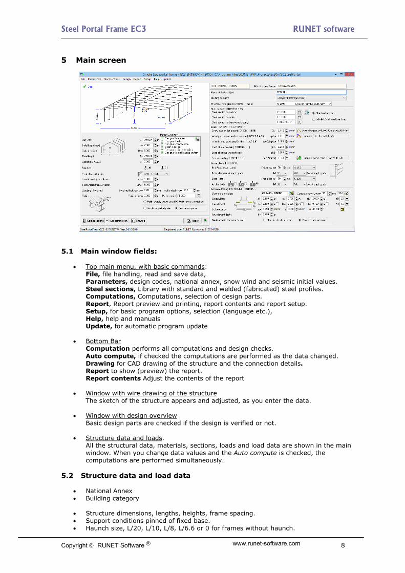
5 Main screen
5.1 Main window fields:
Top main menu, with basic commands: File, file handling, read and save data,
Parameters, design codes, national annex, snow wind and seismic initial values. Steel sections, Library with standard and welded (fabricated) steel profiles. Computations, Computations, selection of design parts. Report, Report preview and printing, report contents and report setup. Setup, for basic program options, selection (language etc.), Help, help and manuals Update, for automatic program update
Bottom Bar Computation performs all computations and design checks.
Auto compute, if checked the computations are performed as the data changed. Drawing for CAD drawing of the structure and the connection details. Report to show (preview) the report. Report contents Adjust the contents of the report
Window with wire drawing of the structure The sketch of the structure appears and adjusted, as you enter the data.
Window with design overview
Basic design parts are checked if the design is verified or not.
Structure data and loads. All the structural data, materials, sections, loads and load data are shown in the main window. When you change data values and the Auto compute is checked, the computations are performed simultaneously.
5.2 Structure data and load data
National Annex Building category
Structure dimensions, lengths, heights, frame spacing. Support conditions pinned of fixed base. Haunch size, L/20, L/10, L/8, L/6.6 or 0 for frames without haunch.
Copyright RUNET Software www.runet-software.com 8

Steel Portal Frame EC3 RUNET software
Roofing dimensions cladding and purlins Continuous or simply supported purlins Spacing of lateral bracing for columns Spacing for lateral torsional constraints for rafters Steel grade Steel sections for columns rafter and bracing. Selection from full library of profiles. Standard or Welded (fabricated) profiles for columns and rafters
Snow load. Can be selected from snow region and altitude. Wind loading. May be selected from wind region, altitude and terrain configuration. Wind internal pressure Roof covering and ceiling load under. Seismic loading. May be selected from seismic region and ground type.
Connection data, plate thickness and steel grade, bolt characteristics. Anchor bolt characteristics
Concrete footing dimensions and material. Properties of foundation soil. Horizontal forces can be resisted with steel tie at column base or passive earth
pressure. 6 10 steps - How to work with the program
1. To avoid the computations being slow, uncheck Auto computation on the left of button line. If it is checked, the computations are performed at the same moment you change some of the data, and your computer might be slow when it is turned on. When the computations are completed, the full design of the structure is done. If the computer is not very fast it may be a small delay when you entering data if the Auto computation is checked. So until you enter all the basic data for the structure and loads keep Auto computations unchecked.
2. Check the National Annex to be appropriate on the top right of the window. If not,
reset from Parameters/National Annex or click on 3. Check snow, wind and earthquake regions. If the regions are not right, reset from
Parameters or click on the corresponding fields. 4. Enter the basic structure dimensions and loads. If the structure is flat enter first H1
and then H. Select pinned or rigid base connection . Specify the haunch size as ratio of total length. 0 when there is no haunch.
5. Select Standard or welded (fabricated) steel profiles for column or rafter sections.
Specify steel sections. Click to pre estimate the section sizes.
6. Click . If an error window appears with messages try to refine the model by changing the cross-sections.
7. Check the window with design overview if all design parts are OK.
8. Preview the Drawing of the structure and details.
9. Click to preview the design report. You can print the report from the preview.
10. Check Auto computation . Refine the design.
Copyright RUNET Software www.runet-software.com 9

Steel Portal Frame EC3 RUNET software
7 Files New, Open, Reopen, Save, Save As A standard windows dialog is displayed, where you should select a file name. Reopen, Keeps a list of the five (5) more recent files, to open them directly. All the data of a project are saved in file *.SteelPortalFrameEC3. After you opened an old or new file the changes are saved automatically. In the folder /examples you will find examples of ready frame structures. 8 Parameters Basic program parameters for materials, design parameters and regions for snow, wind and earthquake loading. 8.1 National Annex Select the National Annex of the country you want to work. To do this first click Locked to unlock. The various design parameters (load factors, material factors etc..) are set according to the National annex. This does don affect the regions for snow, wind and earthquake, which have to be selected from the next menu lines of the parameter menu. 8.2 Materials Structural steel, Concrete, Reinforcing steel and Soils for the foundation. You can change (edit) material properties. In order to avoid accidental material changes the edit capabilities are locked. To edit, click first
to unlock the edit capabilities. With you add or delete lines from the
property tables, with the original program values are loaded.
Copyright RUNET Software www.runet-software.com 10

Steel Portal Frame EC3 RUNET software
8.3 Design Parameters The National Annex parameters are set according to the National Annex you select. You may although want to change some of them, or specify some design considerations not mentioned in the national Annex. 8.3.1 NAD parameters Action coefficients for Ultimate limit states EQU and STR. According to Eurocode 0 Table A1.2A and Table A1.2B. Click Reset to reset to National Annex values. Load Combination coefficients according to Eurocode0 Table A1.1. Click Reset to reset to National Annex values Material factors for Steel according to Eurocode 3 §6.1 Material factors for Reinforced concrete according to Eurocode 2 §2.4.2.4., used for the reinforced concrete in the foundation. Material factors for Soil according to Eurocode 7 Annex A. Used for the foundation design. Eurocode 3, design parameters. Lateral torsional buckling computations base on Eurocode 3 Eq. 6.56, and Tables T 6.3, and T 6.4. (most common) Lateral torsional buckling computations base on Eurocode 3 Eq. 6.57, and Table T 6.5. Method for Bending and compression. Method 1 Annex A or method 2 Annex B (most common)
Copyright RUNET Software www.runet-software.com 11
Steel Portal Frame EC3 RUNET software
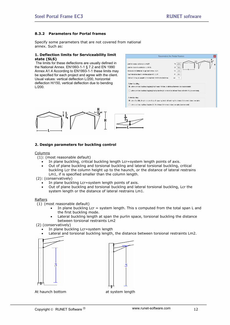
8.3.2 Parameters for Portal frames Specify some parameters that are not covered from national annex. Such as: 1. Deflection limits for Serviceability limit state (SLS) The limits for these deflections are usually defined in the National Annex. EN1993-1-1 § 7.2 and EN 1990 Annex A1.4 According to EN1993-1-1 these limits may be specified for each project and agree with the client. Usual values: vertical deflection L/200, horizontal deflection H/150, vertical deflection due to bending L/200.
2. Design parameters for buckling control Columns (1): (most reasonable default)
In plane buckling, critical buckling length Lcr=system length points of axis. Out of plane buckling and torsional buckling and lateral torsional buckling, critical
buckling Lcr the column height up to the haunch, or the distance of lateral restrains Lm1, if is specified smaller than the column length.
(2): (conservatively) In plane buckling Lcr=system length points of axis. Out of plane buckling and torsional buckling and lateral torsional buckling, Lcr the
system length or the distance of lateral restrains Lm1. Rafters (1) (most reasonable default)
In plane buckling Lcr = system length. This s computed from the total span L and the first buckling mode.
Lateral buckling length at span the purlin space, torsional buckling the distance between torsional restraints Lm2
(2) (conservatively) In plane buckling Lcr=system length Lateral and torsional buckling length, the distance between torsional restraints Lm2.
At haunch bottom at system length
Copyright RUNET Software www.runet-software.com 12
Steel Portal Frame EC3 RUNET software
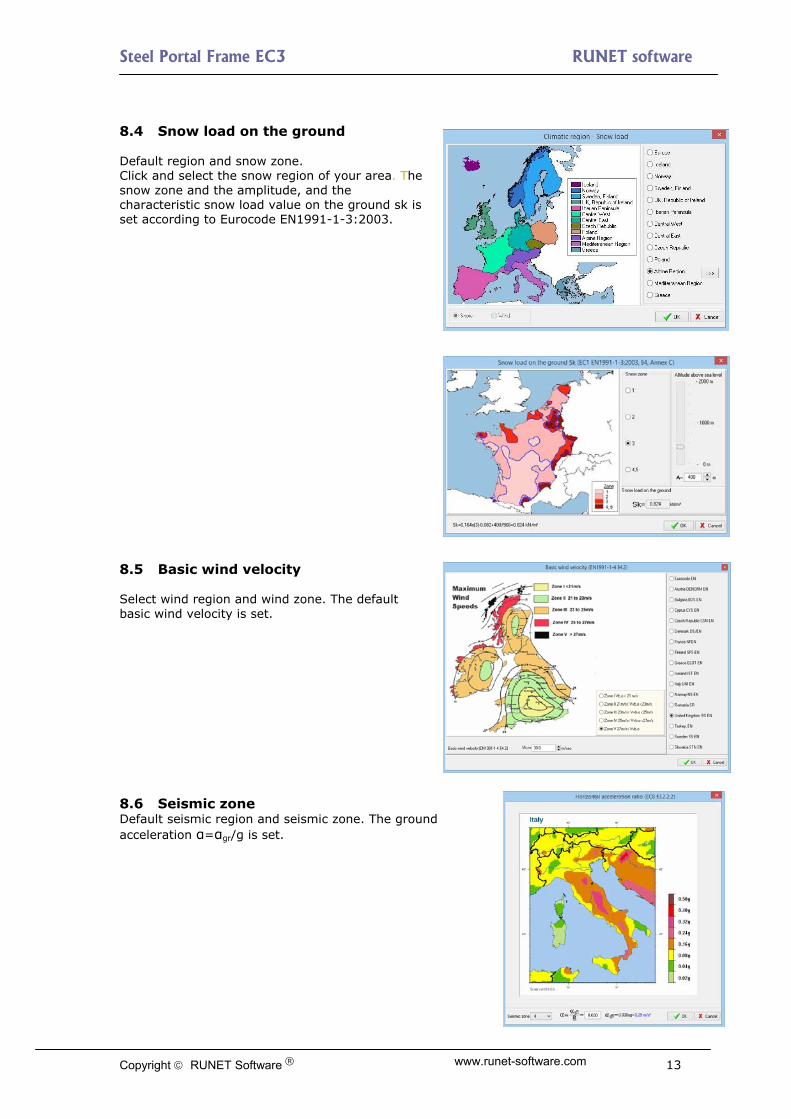
8.4 Snow load on the ground Default region and snow zone. Click and select the snow region of your area. The snow zone and the amplitude, and the characteristic snow load value on the ground sk is set according to Eurocode ΕΝ1991-1-3:2003. 8.5 Basic wind velocity Select wind region and wind zone. The default basic wind velocity is set. 8.6 Seismic zone Default seismic region and seismic zone. The ground acceleration α=αgr/g is set.
Copyright RUNET Software www.runet-software.com 13

Steel Portal Frame EC3 RUNET software
Copyright RUNET Software www.runet-software.com 14
9 Setup 9.1 Language setup Sets program language to Native language or English. Set current data as Default-Initial values. Saves the current structure data. When you start the program next time, these values will be loaded. If you, instead of [Save], click [Reset] the Initial values from the program are loaded. 10 Computations
Click to perform all the
computations, if checked the computations are performed at the same time the data are changed. This may sometimes (if slow computer) delay the changing of input data. It is advised to uncheck Auto computation when you form the model and when you make a lot of input data adjustments. If the sections, plate thickness or bolt diameters, are not adequate, an error window appears with appropriate error messages for the verifications that are not verified. In addition if you preview the report you will see in red extended error messages at the place the calculations or verifications are performed. In the design overview window it is displayed which designs are verified. The program automatically increases plate thicknesses, bolt diameters or foundation width to achieve design verification. 11 Report
Click and the full design report with detailed analysis, drawings and references to Eurocodes is displayed. Warning message, in red colour, appears in the report for the design parts for which the verifications fail. The report is organized in numbered paragraphs. Some basic chapters start on a new page. From Report/Report setup you can select to start every chapter on a new page. In the end of the report an extended table of contents is included.
You go front and back pages in the report or jump to a specific page with From the preview you can print all or part of the report, and export to PDF and Word file.

Steel Portal Frame EC3 RUNET software
In order to select a range of pages to be printed click . The appearance, top or bottom logo, font, margins etc.., is adjusted from Compute-Report/Report setup. It is advisable to don’t change the font used in the report. The font already selected is courier new and it supports certain characters (Greek, mathematical symbols) and it is fixed pitch font so the various formulas and tables are lined correctly.
The contents of the report are adjusted with . You can select the drawings and the chapters that are included in the report. By checking full, medium or short report you can fast select report configurations. Options: Structure drawing is the first wired diagram of the structure, with the basic shape and dimensions. Finite element analysis details gives detailed description and output of the finite element model and matrices, and better not to be checked/marked. CAD structural drawing, CAD Drawing of structure and CAD Drawing of details, are drawing in scale at the end of the report. Visible layers in drawing as in CAD, if checked, the visible layers in the drawings in the end of the report are the same as the ones checked in the CAD drawing, otherwise all the layers are visible. Table of Contents. If checked, a full table of contents is included in the end of the report. The last five(5) options Design of Purlins, Design of connections, Seismic design, Design of concrete footing, Design of lateral bracing system, are design parts which you can choose to be included or not. This is only to include or not include these design parts in the report. If you don’t want to perform these design parts you have to uncheck them from Active design parts.
Copyright RUNET Software www.runet-software.com 15

Steel Portal Frame EC3 RUNET software
11.1 Report menu Compute Perform all the design computations. Report Preview-print the report. Report contents. You can select the drawings and the chapters to appear in the report. Report setup, font settings, captions, footnotes, etc.., for report Printer. Standard dialog to select printer, and printer properties Drawing, opens the CAD drawing window. 11.2 Report setup Report, Adjust the appearance and contents of header, footer report margins and font. Page setup, Select the Paper size, printing on both sides. Paragraphs: Adjust the distance between the report lines, (usually for best appearance 4mm.) You can choose to have each chapter to start on a new page. The errors appear in red or other colour.
Copyright RUNET Software www.runet-software.com 16

Steel Portal Frame EC3 RUNET software
12 CAD Drawings
By clicking you obtain the CAD drawing of the structure and the structural details for the connections.
With the CAD tools you can adjust the appearance of the drawings, print drawing in various forms and paper sizes, export to DXF, PDF, WMF. Select the kind of drawing to be included:
Structure and details Only structure Eave connection detail Apex connection detail
Base connection detail Visible layers are checked in the layer window. The colour and thickness of the line, font size and colour, colour of DXF layer are adjusted in the property window. -Click on screen. When the hand appears as cursor, you can drag and move the drawing up, down, left, right, by pressing the mouse.
- adjust scale of drawing or details.
- move drawing, enable drag. Drag is enabled by clicking on the main drawing.
cursor options and measuring distances.
Copyright RUNET Software www.runet-software.com 17

Steel Portal Frame EC3 RUNET software
Preview, print, export to PDF, WMF, or DXF for AutoCAD or other drawing programs. You enter a new window. From the dialog box you choose the options for paper size and panels appearing at the side of the drawing. By clicking on the drawing (when the hand appears as cursor) you drag the drawing to the place you want to appear into the printout paper. In order to have right appearance or printing, the selected printer has to support the paper option. In case you have problems with right appearance try the paper selection with dimensions. Eg. Instead of A2 Landscape try A2L 420x594. The adjustment of the DXF layers is done in the property window. All the layers are sent to DXF file. 13 Input Data 13.1 Materials Select the steel grade from the steel materials available. Most of the used steel grades are included in the program, and are loaded according to the national Annex you select. You can add steel grades, or change properties for steel grades in the menu Parameters/materials/Structural Steel. The program automatically sets the respective steel properties (fyk, fuk, Es etc.) The material partial factors γM0 γM1, γM2, are set according to the national Annex selected. 13.2 Steel grades included in the program S 235 EN 10025-2 fy40:235;fu40:360 S 275 EN 10025-2 fy40:275;fu40:430 S 355 EN 10025-2 fy40:355;fu40:510 S 450 EN 10025-2 fy40:440;fu40:550 S 275 N/NL EN 10025-3 fy40:275;fu40:390 S 355 N/NL EN 10025-3 fy40:355;fu40:490 S 420 N/NL EN 10025-3 fy40:420;fu40:520 S 460 N/NL EN 10025-3 fy40:460;fu40:540 S 275 M/ML EN 10025-4 fy40:275;fu40:370 S 355 M/ML EN 10025-4 fy40:355;fu40:470 S 420 M/ML EN 10025-4 fy40:420;fu40:520 S 460 M/ML' EN 10025-4 fy40:460;fu40:540 S 235 W EN 10025-5 fy40:235;fu40:360 S 355 W EN 10025-5 fy40:355;fu40:510 S 460 Q/QL EN 10025-6 fy40:460;fu40:570 S 235 H EN 10210-1 fy40:235;fu40:360 S 275 H EN 10210-1 fy40:275;fu40:430 S 355 H EN 10210-1 fy40:355;fu40:510 S 275 NH/NLH EN 10210-1 fy40:275;fu40:390 S 355 NH/NLH EN 10210-1 fy40:355;fu40:490 S 420 NH/NLH EN 10210-1 fy40:420;fu40:540 S 460 NH/NLH EN 10210-1 fy40:460;fu40:560 S 460 NH/NLH EN 10210-1 fy40:460;fu40:560 S 460 NH/NLH EN 10210-1 fy40:460;fu40:560 S 460 NH/NLH EN 10210-1 fy40:460;fu40:560
Copyright RUNET Software www.runet-software.com 18

Steel Portal Frame EC3 RUNET software
13.3 Cross-sections Specify the cross section for the columns, the rafters, purlins and transverse bracing. All the standard hot- rolled or cold-format cross sections are included.
Click , and the library with the standard section will open. You select the section type on the left tree and at the same time all the sections of this group with their geometric properties are displayed on the right window together with the section drawing in scale. Section geometric properties are calculated precisely including fillets. The notation is shown at the drawing at the low left window. 13.3.1 Estimate of member sizes.
Click and you get a rough estimate of member sizes for the structural elements of the structure with the dimensions you have specified. You can start with this estimate to continue for better design. 13.3.2 Standard types of cross section profiles included in the program
D= 10.2 – 1016 mm
Copyright RUNET Software www.runet-software.com 19

Steel Portal Frame EC3 RUNET software
13.3.3 Welded (fabricated) cross sections If you specify (check) welded cross sections for the columns and rafters, the library with the cross sections defined from the user appears to select cross section. This library is updated from the menu Steel-sections/Welded sections.
Click at Edit to update or change the properties. to add or remove sections. In the window that appears, enter the name of the profile and the values for total height h in mm, total width b in mm, web thickness tw in mm, flange thickness tf in mm, and weld seam a in mm.
Copyright RUNET Software www.runet-software.com 20
Steel Portal Frame EC3 RUNET software
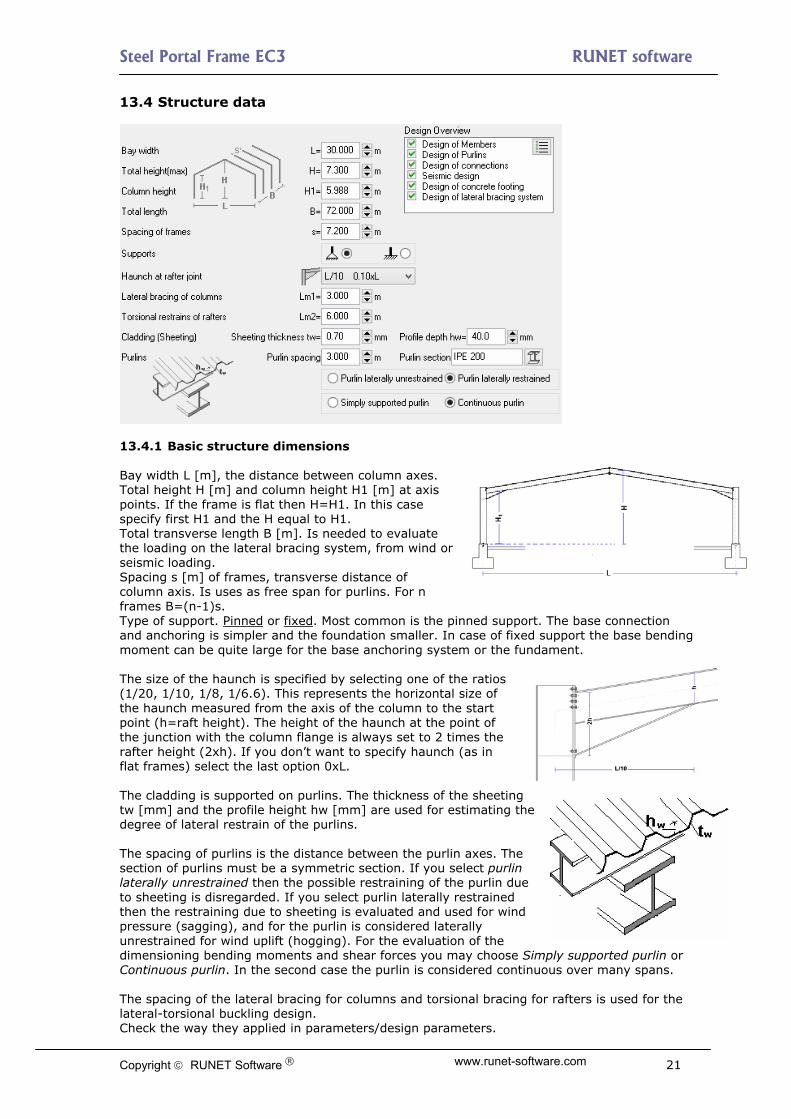
13.4 Structure data
13.4.1 Basic structure dimensions Bay width L [m], the distance between column axes. Total height H [m] and column height H1 [m] at axis points. If the frame is flat then H=H1. In this case specify first H1 and the H equal to H1. Total transverse length B [m]. Is needed to evaluate the loading on the lateral bracing system, from wind or seismic loading. Spacing s [m] of frames, transverse distance of column axis. Is uses as free span for purlins. For n frames B=(n-1)s. Type of support. Pinned or fixed. Most common is the pinned support. The base connection and anchoring is simpler and the foundation smaller. In case of fixed support the base bending moment can be quite large for the base anchoring system or the fundament. The size of the haunch is specified by selecting one of the ratios (1/20, 1/10, 1/8, 1/6.6). This represents the horizontal size of the haunch measured from the axis of the column to the start point (h=raft height). The height of the haunch at the point of the junction with the column flange is always set to 2 times the rafter height (2xh). If you don’t want to specify haunch (as in flat frames) select the last option 0xL. The cladding is supported on purlins. The thickness of the sheeting tw [mm] and the profile height hw [mm] are used for estimating the degree of lateral restrain of the purlins. The spacing of purlins is the distance between the purlin axes. The section of purlins must be a symmetric section. If you select purlin laterally unrestrained then the possible restraining of the purlin due to sheeting is disregarded. If you select purlin laterally restrained then the restraining due to sheeting is evaluated and used for wind pressure (sagging), and for the purlin is considered laterally unrestrained for wind uplift (hogging). For the evaluation of the dimensioning bending moments and shear forces you may choose Simply supported purlin or Continuous purlin. In the second case the purlin is considered continuous over many spans. The spacing of the lateral bracing for columns and torsional bracing for rafters is used for the lateral-torsional buckling design. Check the way they applied in parameters/design parameters.
Copyright RUNET Software www.runet-software.com 21

Steel Portal Frame EC3 RUNET software
13.5 Loads The program automatically forms and evaluates all the load combinations in ultimate limit state ULS (EQU,STR), and serviceability limit state SLS. The partial factors for loading and load combination factors are taken according to Eurocode 0 and National Annex. The basic loads are:
13.5.1 Permanent loads
Load of roof covering [kN/m²] It includes the weight of the sheeting, purlins and insulation materials.
Load of ceiling under the roof [kN/m²] self weight of frame elements, calculated by the program from the element cross
sections with Unit mass ρ= 7850 Kg/m³ 13.5.2 Variable loads
Imposed load according to EN1990-1-1 Tab 6.1, calculated by the program according to the selected National Annex
Snow load according to Eurocode 1-3:2004
The characteristic snow load on the ground sk is specified in kN/m2.
Click , and a special dialog window appear. In this window you set the snow zone and the height above the sea level. The characteristic snow load on the ground is computed according to Eurocode 1-3:2004, and the National Annex. The snow region can be selected from Parameters/snow load on the ground. The snow load on the roof is computed according to Eurocode 1-3:2003.
Wind load, according to Eurocode 1-
4:2005
The wind pressure on vertical surface is
specified in kN/m2. Click and in this window you compute the wind pressure from the wind velocity and the topography of the region according to Eurocode 1-4:2005. The wind load is computed for various places at the roof and the vertical walls according to Eurocode 1-4:2005 §7.2.5 and Tab 7.4a and Tab. 7.1. The wind region, which specifies the wind velocity, is selected from Parameters/Basic wind velocity. Wind internal pressure wi in kN/m2. This is internal pressure and it acts from inside outwards on the walls and roof. It is subtracted directly (without further multiplication by pressure coefficients) from any uplift wind pressure on the outside surfaces.
Copyright RUNET Software www.runet-software.com 22

Steel Portal Frame EC3 RUNET software
13.5.3 Seismic load Eurocode 8-1:2004 The program performs a verification of the structure under seismic loading, using both Lateral force method, and Modal superposition spectrum
analysis. . Basic value used in the seismic design is the ratio
of horizontal seismic acceleration. Click and a special dialog window appears where you may in detail specify all the necessary seismic parameters (soil factors, spectra periods, behaviour factors, etc..) for the design spectrum, according to Eurocode 8-1:2004. 13.6 Connections Apex and eave bolt-connections with end plate are designed to resist moment and shear forces. For the apex and eave connection the end plate (thickness and steel grade) and bolts (diameter, grade) are the same. The thickness of Apex and eave end plate should be at least as thick as the flange thickness of the rafter and column section. At the base of the haunch, a stiffener is designed to resist the increased compressive forces. Base plate bolt-connection is designed for the column over the concrete foundation. The anchor bolts are designed to resist shear and pullout forces due to uplift wind or seismic forces. CEN/TS 1992-4-1:1992 and CEN/TS 1992-4-2:1992 are used for the design of the fastenings in concrete. The holding down anchor bolts of the base plate are extended with anchors. The anchor system can be (simple hook, bended hook or washer plate). The hook type anchoring (first two choices) cannot be selected for bolt grade with fy>300N/mm2 (M>5.6), according to Eurocode 1993-1-8:2005, 6.2.6.12 (6). The program will, if it is necessary, increase the diameter of the bolts or the thickness of the connection plate to satisfy the design checks. Connections are designed according to EN1993-1-8. 13.7 Foundation The concrete footing has to be designed to resist soil pressure for maximum vertical load, and it must have enough weight to resist uplift (from wind or seismic forces).
Reinforced concrete properties
Click and select concrete and steel class. Click to select concrete cover Cnom [mm]
Fundament dimensions Specify the dimensions of the short column above the fundament cross-section dimensions cx and cy and height ch, and next the diameter of the column main reinforcing bars for the CAD drawing.
Copyright RUNET Software www.runet-software.com 23

Steel Portal Frame EC3 RUNET software
The dimensions of the fundament Bx width lengthwise, By width in transverse direction, Bh the height of the fundament, and the size of the reinforcing bars of the fundament. The program may change the footing dimensions chosen by the user to fulfil the design criteria for the foundation design. If you don’t want a footing dimension to be changed then check the box next to the dimension.
Soil properties, soil bearing capacity qu [N/mm2], soil unit weight γ KN/m3, and soil
angle of internal friction φ, can be selected by click .
Foundation depth hf is the depth of the bottom of the fundament. This depth is used for the computation of the passive earth resistance.
The high horizontal forces acting at the base are acting outwards as a result of bending in the columns due to vertical loading on the roof. This is resisted in two ways.
Steel tie at column base A tie cast into the floor slab connected to the base of the columns. This should be considered more safe method to resist the horizontal forces at the base of the columns
Passive earth pressure on the side of the foundation.
In this case the earth filling and compacting on the side of the foundation must be performed carefully, so that the passive earth pressure is not reduced. The fundament transverse width By and the height Bh are used to compute the active area for passive earth pressure.
It is advisable to check the desired fundament height Bh on the side and let the dimensions Bx and By to be adjusted by the program. Bx and By are adjusted so the fundament weight has enough weight to resist uplift, (the foundation is also an important factor). By is adjusted also for adequate passive earth force to resist the horizontal base force outwards. 13.7.1 Foundation bearing resistance The basis for the design of foundations is the bearing resistance of the soil. The design bearing resistance may be calculated using analytical or semi-empirical methods. Annex D of Eurocode 7 EN1997:2004 describes a method of obtaining the design bearing strength of the soil. The methods of Annex D for drained and undrained conditions are implemented in the program. The Design bearing strength of the soil is estimated for EQU, STR and GEO conditions. The computation of design bearing strength is for drained and undrained soil conditions. For drain soil conditions the important soil property is the angle of shearing resistance φk [°] and the cohesion intercept c[kPA]. For undrained soil conditions the important soil property is the undrained strength cu [kPa]. For the computation of design bearing strength other parameters are the dimensions and foundation depth of the footing, as well as the loading and the load eccentricities.
Copyright RUNET Software www.runet-software.com 24

Steel Portal Frame EC3 RUNET software
In the foundation design of the program for the soil strength we use the soil bearing pressure quk (N/mm2). This is corresponding soil strength to the soil allowable pressure. In the foundation design we use as design bearing soil pressure qud=quk/γqu, where γqu is the partial factor for unconfined strength. (Eurocode 7, Annex A). So to be consistent in order to convert the design strength estimated from Annex D of Eurocode7 to the soil bearing pressure used in the program the design value have to be multiplied by γqu, quk = qud. γqu. γqu =1.40 for EQU and 1.00 and 1.4 for STR-GEO.
Click in the design of fundaments, and you get into a calculation window for design bearing resistance. There you have an estimate of the soil bearing resistance quk which you may use in the program, from the soil and fundament parameters. If there you check to include the calculations in the report, then the design bearing resistance will be set to the minimum estimated and the calculations will be included in the report of the footing design (remember that if you alter the dimensions or loading you have to reevaluate quk).
Copyright RUNET Software www.runet-software.com 25

Steel Portal Frame EC3 RUNET software
14 Design Considerations Active parts of the design.
Design of members (always active) Design of purlins Design of connections Seismic design Design of concrete foundation Design of lateral bracing system
On the design overview you can see the various parts of the design. A green check OK shows that this part of design is verified, a red cross shows inadequate design. If there are no marks
then this design part is not active. Active design parts are selected by click at or from the
report contents, . 15 Error messages When the verification checks are not satisfied, error messages appear in red in the report and in a special window that appears on the main screen. These errors are:
acr=Fcr/Fed<3, Change cross-sections, or perform second-order analysis §5.2.2.1 Second order effects are significant in dynamic analysis EC8 §4.4.2.2(2), θ>0.2 and
second order P-D affects must be taken into account with a second order analysis. If θ<0.2 the program uses the multiplier 1/(1- θ) to take into account the second order effects.
Limit for Vertical deflection is exceeded. (SLS serviceability limit state EC3 §7.2.1). The limit value can be st in menu Parameters/design parameters
Limit for Horizontal deflection (SLS serviceability limit state (EC3 §7.2.2). The limit value can be st in menu Parameters/design parameters
verification of cross section resistance Ned<Nrd, Ved<Vrd, Med<Mrd are not satisfied , (EC3 §6.2.4, §6.2.5, §6.2.6) and combined Ned+Ved+Med (EC3 §6.2.9, §6.2.10) If not satisfy you must change sections for column or rafter
verification of Buckling check compression, Nc,ed<Nb,rd (EC3 §6.3.1) verification of Bucking check bending, My,ed<Mr,rd (EC3 §6.3.2) verification of Lateral torsional buckling equations 6.61 and 6.62 , EC3 §6.3.2. if the
buckling checks are not satisfied you must select stiffer cross-sections for column or rafter or you must reduce the spacing of lateral restraints
Copyright RUNET Software www.runet-software.com 26

Steel Portal Frame EC3 RUNET software
16 Short theoretical overview 16.1 Design Loads EN1991:2005 : 16.1.1 Permanent loads EN1991-1:2005 Weight of the roof system (sheeting+purlins+insulation) Weight of the ceiling structure (if any) Self-weight of the portal frame elements (calculated by the program) 16.1.2 Imposed loads EN1991-1:2005 A distributed imposed load qk according to Eurocode 1 EN1991-1-1 Tab 6.1 is considered on top of the roof. 16.1.3 Snow load EN1991-3:2003 Snow load is computed according to Eurocode 1-3 EN1991-3:2003, from the characteristic snow load on the ground and the roof slope. s=μi Ce Ct sk (EN1991-3:2003 §5.2) [kN/m²] The three characteristic load arrangements of EN1991-3:2003 §5.3.3 are
considered in the load cases. If the frame is flat (α=0°) one load arrangement is considered s= 0.80 Ce Ct sk. The characteristic snow load on the ground sk can be defined directly by selecting the snow region, snow zone and the altitude, according to EN1991-3:20 Annex C. The snow load arrangements according to Eurocode 1-3 are Flat roofs. Load case (I) Pitched roofs Load cases (I) (II) III) If the roof slop is low, only snow load arrangement (I) is necessary. The limit slope for this is angle a=2°. You can set this angle to a bigger value at Parameters/Design parameters/ parameters for Portal frames. 16.1.4 Wind load of EN1991-4:2005 Wind load is computed according to of EN1991-4:2005 §7.2.5 from the wind peak velocity pressure q(z). Wind pressure on surfaces we=q(z)·Cpe [kN/m²] The wind pressure coefficients Cpe are computed from EN1991-4:2005 Tab.74a for roof surfaces and EN1991-4:2005 Tab 7.1 for the vertical wall surfaces. The wind peak velocity pressure q(z), can be defined directly from the wind velocity the terrain roughness and the oreography. According to EN1991-4:2005 §4.5 and Annex A.
The wind pressure or underpressure on roof and wall surface are computed according to Eurocode 1-4. For roof slopes (α<=8ο) one load arrangement is considered. For higher slope values two wind load cases are considered according to the pressure coefficients of Table 7.4a of Eurocode 1-4. The specified internal pressure is always added (increase underpressure) to the external wind pressure situation. 16.1.5 Earthquake loading EN1998-1:2004 The earthquake loading is defined from the ground acceleration and the design spectrum according to Eurocode 8 EN1998-1:2004.
Copyright RUNET Software www.runet-software.com 27

Steel Portal Frame EC3 RUNET software
16.2 Design load combinations EN1990:2002 All the necessary load combinations defined in Eurocode0 EN1990:2002 are considered and the resulting design forces are checked in the strength verifications. 16.2.1 Load combination factors (EN1990 Tab.A1.1) Category H (roofs) Qk ψο=0.00, ψ1=0.00, ψ2=0.00 Snow loads on buildings Qs ψο=0.50, ψ1=0.20, ψ2=0.00 Wind loads on buildings Qw ψο=0.60, ψ1=0.20, ψ2=0.00 16.2.2 Ultimate Limit State (ULS) (EQU) Ed = γG·Gk + γQ·Qk1 + γQ·ψο·Qk2 (Eq.6.10) γG,sup=1.10 (Unfavourable) γG,inf=0.90 (Favourable) γQ =1.50 (Unfavourable) γQ =0.00 (Favourable) Load combinations (ULS)(EQU), Permanent load Gk, Imposed load Qk, Snow load Qs1,Qs2,Qs3, Wind load Qw1,Qw2 L.C. 101: 1.10Gk+1.50Qk (Eq.6.10) L.C. 102: 1.10Gk+1.50Qs1 (Eq.6.10) L.C. 103: 1.10Gk+1.50Qs2 (Eq.6.10) L.C. 104: 1.10Gk+1.50Qs3 (Eq.6.10) L.C. 105: 1.10Gk+1.50Qw1 (Eq.6.10) L.C. 106: 1.10Gk+1.50Qw2 (Eq.6.10) L.C. 111: 0.90Gk+1.50Qw1 (Eq.6.10) L.C. 121: 1.10Gk+1.50Qs1+0.60x1.50Qw1= 1.10xGk+1.50Qs1+0.90Qw1 (Eq.6.10) L.C. 122: 1.10Gk+1.50Qs1+0.60x1.50Qw2= 1.10xGk+1.50Qs1+0.90Qw2 (Eq.6.10) L.C. 123: 1.10Gk+1.50Qs2+0.60x1.50Qw1= 1.10xGk+1.50Qs2+0.90Qw1 (Eq.6.10) L.C. 124: 1.10Gk+1.50Qs2+0.60x1.50Qw2= 1.10xGk+1.50Qs2+0.90Qw2 (Eq.6.10) L.C. 125: 1.10Gk+1.50Qs3+0.60x1.50Qw1= 1.10xGk+1.50Qs3+0.90Qw1 (Eq.6.10) L.C. 126: 1.10Gk+1.50Qs3+0.60x1.50Qw2= 1.10xGk+1.50Qs3+0.90Qw2 (Eq.6.10) L.C. 127: 1.10Gk+1.50Qw1+0.50x1.50Qs1= 1.10xGk+1.50Qw1+0.75Qs1 (Eq.6.10) L.C. 128: 1.10Gk+1.50Qw1+0.50x1.50Qs2= 1.10xGk+1.50Qw1+0.75Qs2 (Eq.6.10) L.C. 129: 1.10Gk+1.50Qw1+0.50x1.50Qs3= 1.10xGk+1.50Qw1+0.75Qs3 (Eq.6.10) L.C. 130: 1.10Gk+1.50Qw2+0.50x1.50Qs1= 1.10xGk+1.50Qw2+0.75Qs1 (Eq.6.10) L.C. 131: 1.10Gk+1.50Qw2+0.50x1.50Qs2= 1.10xGk+1.50Qw2+0.75Qs2 (Eq.6.10) L.C. 132: 1.10Gk+1.50Qw2+0.50x1.50Qs3= 1.10xGk+1.50Qw2+0.75Qs3 (Eq.6.10) 16.2.3 Ultimate Limit State (ULS) (STR) Ed = γG·Gk + γQ·Qk1 + γQ·ψο·Qk2 (Eq.6.10) Ed = γG·Gk + γQ·ψο·Qk1 + γQ·ψο·Qk2 (Eq.6.10a) Ed = ξ·γG·Gk + γQ·Qk1 + γQ·ψο·Qk2 (Eq.6.10b) γG,sup=1.35 (Unfavourable) γG,inf=1.00 (Favourable) γQ =1.50 (Unfavourable) γQ =0.00 (Favourable) ξ=0.850, ξ·γG=0.850x1.35=1.15 Load combinations (ULS)(STR), Permanent load Gk, Imposed load Qk, Snow load Qs1,Qs2,Qs3, Wind load Qw1,Qw2 L.C. 201: 1.35Gk+1.50Qk (Eq.6.10) L.C. 202: 1.35Gk+1.50Qs1 (Eq.6.10) L.C. 203: 1.35Gk+1.50Qs2 (Eq.6.10) L.C. 204: 1.35Gk+1.50Qs3 (Eq.6.10) L.C. 205: 1.35Gk+1.50Qw1 (Eq.6.10) L.C. 206: 1.35Gk+1.50Qw2 (Eq.6.10) L.C. 211: 1.35Gk+1.50Qs1+0.60x1.50Qw1= 1.35xGk+1.50Qs1+0.90Qw1 (Eq.6.10) L.C. 212: 1.35Gk+1.50Qs1+0.60x1.50Qw2= 1.35xGk+1.50Qs1+0.90Qw2 (Eq.6.10) L.C. 213: 1.35Gk+1.50Qs2+0.60x1.50Qw1= 1.35xGk+1.50Qs2+0.90Qw1 (Eq.6.10) L.C. 214: 1.35Gk+1.50Qs2+0.60x1.50Qw2= 1.35xGk+1.50Qs2+0.90Qw2 (Eq.6.10) L.C. 215: 1.35Gk+1.50Qs3+0.60x1.50Qw1= 1.35xGk+1.50Qs3+0.90Qw1 (Eq.6.10) L.C. 216: 1.35Gk+1.50Qs3+0.60x1.50Qw2= 1.35xGk+1.50Qs3+0.90Qw2 (Eq.6.10) L.C. 217: 1.35Gk+1.50Qw1+0.50x1.50Qs1= 1.35xGk+1.50Qw1+0.75Qs1 (Eq.6.10) L.C. 218: 1.35Gk+1.50Qw1+0.50x1.50Qs2= 1.35xGk+1.50Qw1+0.75Qs2 (Eq.6.10) L.C. 219: 1.35Gk+1.50Qw1+0.50x1.50Qs3= 1.35xGk+1.50Qw1+0.75Qs3 (Eq.6.10)
Copyright RUNET Software www.runet-software.com 28

Steel Portal Frame EC3 RUNET software
L.C. 220: 1.35Gk+1.50Qw2+0.50x1.50Qs1= 1.35xGk+1.50Qw2+0.75Qs1 (Eq.6.10) L.C. 221: 1.35Gk+1.50Qw2+0.50x1.50Qs2= 1.35xGk+1.50Qw2+0.75Qs2 (Eq.6.10) L.C. 222: 1.35Gk+1.50Qw2+0.50x1.50Qs3= 1.35xGk+1.50Qw2+0.75Qs3 (Eq.6.10) L.C. 231: 1.35Gk+1.50x0.50Qs1 +1.50x0.60Qw1= 1.35xG+0.75Qs1+0.90Qw1 (Eq.6.10a) L.C. 232: 1.35Gk+1.50x0.50Qs1 +1.50x0.60Qw2= 1.35xG+0.75Qs1+0.90Qw2 (Eq.6.10a) L.C. 233: 1.35Gk+1.50x0.50Qs2 +1.50x0.60Qw1= 1.35xG+0.75Qs2+0.90Qw1 (Eq.6.10a) L.C. 234: 1.35Gk+1.50x0.50Qs2 +1.50x0.60Qw2= 1.35xG+0.75Qs2+0.90Qw2 (Eq.6.10a) L.C. 235: 1.35Gk+1.50x0.50Qs3 +1.50x0.60Qw1= 1.35xG+0.75Qs3+0.90Qw1 (Eq.6.10a) L.C. 236: 1.35Gk+1.50x0.50Qs3 +1.50x0.60Qw2= 1.35xG+0.75Qs3+0.90Qw2 (Eq.6.10a) L.C. 251: 0.850x1.35Gk+1.50Qs1+1.50x0.60Qw1= 1.15xG+1.50Qs1+0.90Qw1 (Eq.6.10b) L.C. 252: 0.850x1.35Gk+1.50Qs1+1.50x0.60Qw2= 1.15xG+1.50Qs1+0.90Qw2 (Eq.6.10b) L.C. 253: 0.850x1.35Gk+1.50Qs2+1.50x0.60Qw1= 1.15xG+1.50Qs2+0.90Qw1 (Eq.6.10b) L.C. 254: 0.850x1.35Gk+1.50Qs2+1.50x0.60Qw2= 1.15xG+1.50Qs2+0.90Qw2 (Eq.6.10b) L.C. 255: 0.850x1.35Gk+1.50Qs3+1.50x0.60Qw1= 1.15xG+1.50Qs3+0.90Qw1 (Eq.6.10b) L.C. 256: 0.850x1.35Gk+1.50Qs3+1.50x0.60Qw2= 1.15xG+1.50Qs3+0.90Qw2 (Eq.6.10b) L.C. 257: 0.850x1.35Gk+1.50Qw1+1.50x0.50Qs1= 1.15xG+1.50Qw1+0.75Qs1 (Eq.6.10b) L.C. 258: 0.850x1.35Gk+1.50Qw1+1.50x0.50Qs2= 1.15xG+1.50Qw1+0.75Qs2 (Eq.6.10b) L.C. 259: 0.850x1.35Gk+1.50Qw1+1.50x0.50Qs3= 1.15xG+1.50Qw1+0.75Qs3 (Eq.6.10b) L.C. 260: 0.850x1.35Gk+1.50Qw2+1.50x0.50Qs1= 1.15xG+1.50Qw2+0.75Qs1 (Eq.6.10b) L.C. 261: 0.850x1.35Gk+1.50Qw2+1.50x0.50Qs2= 1.15xG+1.50Qw2+0.75Qs2 (Eq.6.10b) L.C. 262: 0.850x1.35Gk+1.50Qw2+1.50x0.50Qs3= 1.15xG+1.50Qw2+0.75Qs3 (Eq.6.10b) 16.2.4 Serviceability Limit State (SLS) Ed = Gk + Qk1 + ψο·Qk2 + ψο·Qk3 (Characteristic combination) (Eq.6.14b) Ed = Gk + ψ1·Qk1 + ψ2·Qk2 + ψ2·Qk3 (Frequent combination) (Eq.6.15b) Ed = Gk + ψ2·Qk1 + ψ2·Qk2 + ψ2·Qk3 (Quasi-permanent combination) (Eq.6.16b) Load combinations (SLS) Permanent load Gk, Imposed load Qk, Snow load Qs1,Qs2,Qs3, Wind load Qw1,Qw2 L.C. 301: Gk+Qk (Eq.6.14a) L.C. 302: Gk+Qs1 (Eq.6.14a) L.C. 303: Gk+Qs2 (Eq.6.14a) L.C. 304: Gk+Qs3 (Eq.6.14a) L.C. 305: Gk+Qw1 (Eq.6.14a) L.C. 306: Gk+Qw2 (Eq.6.14a) L.C. 311: G + Qs1 + 0.60Qw1 (Eq.6.14a) L.C. 312: G + Qs1 + 0.60Qw2 (Eq.6.14a) L.C. 313: G + Qs2 + 0.60Qw1 (Eq.6.14a) L.C. 314: G + Qs2 + 0.60Qw2 (Eq.6.14a) L.C. 315: G + Qs3 + 0.60Qw1 (Eq.6.14a) L.C. 316: G + Qs3 + 0.60Qw2 (Eq.6.14a) L.C. 317: G + Qw1 + 0.50Qs1 (Eq.6.14a) L.C. 318: G + Qw1 + 0.50Qs2 (Eq.6.14a) L.C. 319: G + Qw1 + 0.50Qs3 (Eq.6.14a) L.C. 320: G + Qw2 + 0.50Qs1 (Eq.6.14a) L.C. 321: G + Qw2 + 0.50Qs2 (Eq.6.14a) L.C. 322: G + Qw2 + 0.50Qs3 (Eq.6.14a) L.C. 331: G + 0.50Qs1 + 0.30Qw1 (Eq.6.15a) L.C. 332: G + 0.50Qs1 + 0.30Qw2 (Eq.6.15a) L.C. 333: G + 0.50Qs2 + 0.30Qw1 (Eq.6.15a) L.C. 334: G + 0.50Qs2 + 0.30Qw2 (Eq.6.15a) L.C. 335: G + 0.50Qs3 + 0.30Qw1 (Eq.6.15a) L.C. 336: G + 0.50Qs3 + 0.30Qw2 (Eq.6.15a) L.C. 337: G + 0.20Qw1 + 0.00Qs1 (Eq.6.15a) L.C. 338: G + 0.20Qw1 + 0.00Qs2 (Eq.6.15a) L.C. 339: G + 0.20Qw1 + 0.00Qs3 (Eq.6.15a) L.C. 340: G + 0.20Qw2 + 0.00Qs1 (Eq.6.15a) L.C. 341: G + 0.20Qw2 + 0.00Qs2 (Eq.6.15a) L.C. 342: G + 0.20Qw2 + 0.00Qs3 (Eq.6.15a) L.C. 351: G + 0.00Qs1 + 0.30Qw1 (Eq.6.16a) L.C. 352: G + 0.00Qs1 + 0.30Qw2 (Eq.6.16a) L.C. 353: G + 0.00Qs2 + 0.30Qw1 (Eq.6.16a) L.C. 354: G + 0.00Qs2 + 0.30Qw2 (Eq.6.16a) L.C. 355: G + 0.00Qs3 + 0.30Qw1 (Eq.6.16a) L.C. 356: G + 0.00Qs3 + 0.30Qw2 (Eq.6.16a) 16.2.5 Ultimate Limit State (ULS)Seismic situation
Copyright RUNET Software www.runet-software.com 29

Steel Portal Frame EC3 RUNET software
Ed = Gk + Aed + ψ2·Qk1 + ψ2·Qk2 + ψ2·Qk3 (Eq.6.12b) Snow load Qs, Wind load Qw, Seismic load Aed L.C. 601: Gk + 0.30Qs1 + Aed (Eq.6.14a) 16.3 Finite element model The structure displacements and the internal forces and moments in the structure are calculated with the finite element program FRAME2Dexpress® (©RUNET). The Finite element model uses 2-dimensinal beam elements. The axes of the elements are passing from the centroid of the cross-sections of the beams and the columns. The effective span of the portal frame is the distance between the center lines of the columns. The increase of the stiffness of the rafter elements due to the haunches is taken into account by modifying the element stiffness matrix of the rafter elements. Linear static and dynamic elastic analysis is performed. The eave and apex connections are modelled as stiff connections. The base connection is considered pin or fixed connection according to the selection of the user. The horizontal force acting outwards is resisted either by the passive earth force or by a steel tie placed into the floor slab. 16.4 Materials ΕΝ 1993-1-1:2005 § 3.2 The steel grades listed in Eurocode EN 1993-1-1 Table 3.1 and EN 1993-1-3 are included in the program. The steel properties (yield strength fy and ultimate strength fu) can be changed from Parameters/Material. Design values for: Modulus of elasticity E=210000 N/mm², Poisson ratio ν=0.30, Unit mass ρ= 7850 Kg/m³ Steel grades S 235 EN 10025-2 fy:235 fu:360 S 275 EN 10025-2 fy:275 fu:430 S 355 EN 10025-2 fy:355 fu:510 S 450 EN 10025-2 fy:440 fu:550 S 275 N/NL EN 10025-3 fy:275 fu:390 S 355 N/NL EN 10025-3 fy:355 fu:490 S 420 N/NL EN 10025-3 fy:420 fu:520 S 460 N/NL EN 10025-3 fy:460 fu:540 S 275 M/ML EN 10025-4 fy:275 fu:370 S 355 M/ML EN 10025-4 fy:355 fu:470 S 420 M/ML EN 10025-4 fy:420 fu:520 S 460 M/ML' EN 10025-4 fy:460 fu:540 S 235 W EN 10025-5 fy:235 fu:360 S 355 W EN 10025-5 fy:355 fu:510 S 460 Q/QL EN 10025-6 fy:460 fu:570 S 235 H EN 10210-1 fy:235 fu:360 S 275 H EN 10210-1 fy:275 fu:430 S 355 H EN 10210-1 fy:355 fu:510 S 275 NH/NLH EN 10210-1 fy:275 fu:390 S 355 NH/NLH EN 10210-1 fy:355 fu:490 S 420 NH/NLH EN 10210-1 fy:420 fu:540 S 460 NH/NLH EN 10210-1 fy:460 fu:560 S 460 NH/NLH EN 10210-1 fy:460 fu:560 S 460 NH/NLH EN 10210-1 fy:460 fu:560 S 460 NH/NLH EN 10210-1 fy:460 fu:560 16.5 Partial factors ΕΝ 1993-1-1:2005 § 6.1 The partial factors γΜ are applied to various characteristics resistance values. The partial factors are defined in the program from the selected National Annex., and can be overwritten in Parameters/National Annex parameters. Usual values for steel structures γΜ0 = 1.00
Copyright RUNET Software www.runet-software.com 30

Steel Portal Frame EC3 RUNET software
γΜ1 = 1.00
γΜ2 = 1.25 Usual values for concrete structures (EN1992-1-1 Tab. 2.1N) γc = 1.50 (concrete) γs = 1.15 (reinforcing steel) 16.6 Second order effects EN1993-1-1 §5.2.1 The material behaviour is considered linear elastic. The second order effects are geometrical (P-Δ and P-δ) effects. The practical consequence of (P-Δ)-effects is to reduce the stiffness of the frame, with a result the increase of the deflections and the internal forces beyond the ones calculated from first-order analysis. The effects of the deformed geometry are quantified using the factor acr EN1993-1-1 §5.2.1 acr=Fcr/Fed EN1993-1-1 Eq. (5.1) Fed: is the design loading of the structure Fcr : is the elastic critical buckling load for global instability mode based on initial elastic stiffness. The frame is considered sufficiently stiff and second order effects may be ignored in a first order analysis if acr ≥ 10 For portal frames with shallow slopes according to EN1993-1-1 §5.2.1 (4) acr can be estimated as
αcr =
EdHEd
Ed h
V
H
, EN1993-1-1 Eq (5.2)
Hed : total design the total design horizontal load Ved : total design vertical load δhed : is the horizontal displacement at the top of the columns h : is the column height Axial force in the rafters may be assumed to be significant if
Ed
y
N
Af5.0 EN1993-1-1 Eq (5.3)
According to EN1993-1-1 §5.2.2 (5), single story portal frames designed based on elastic analysis the global analysis second order effects due to vertical load may be calculated by increasing the horizontal loads Hed by equivalent loads φ Ved due to imperfections and other possible sway effects according to the first order theory by an amplification factor
cr11
1
provided that acr ≥ 3 EN1993-1-1 Eq (5.4)
If αcr < 3, second order analysis is necessary 16.7 Imperfections EN1993-1-1 §5.3.1 Global initial sway imperfection: φ = φ0 αh φm φ0: Initial value =1/200 αh: Reduction factor for column height = 2/√h (2/3 ≤ αh ≤ 1) (h: structure height)
φm: Reduction factor for number of columns in a row αm = m115.0
Copyright RUNET Software www.runet-software.com 31
Steel Portal Frame EC3 RUNET software
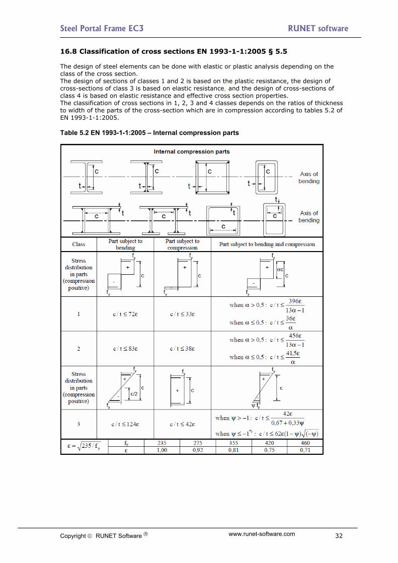
16.8 Classification of cross sections ΕΝ 1993-1-1:2005 § 5.5 The design of steel elements can be done with elastic or plastic analysis depending on the class of the cross section. The design of sections of classes 1 and 2 is based on the plastic resistance, the design of cross-sections of class 3 is based on elastic resistance, and the design of cross-sections of class 4 is based on elastic resistance and effective cross section properties. The classification of cross sections in 1, 2, 3 and 4 classes depends on the ratios of thickness to width of the parts of the cross-section which are in compression according to tables 5.2 of ΕΝ 1993-1-1:2005. Table 5.2 ΕΝ 1993-1-1:2005 – Internal compression parts
Copyright RUNET Software www.runet-software.com 32

Steel Portal Frame EC3 RUNET software
Table 5.2 ΕΝ 1993-1-1:2005 – Outstanding flanges
Table 5.2 ΕΝ 1993-1-1:2005 - Angles
Copyright RUNET Software www.runet-software.com 33

Steel Portal Frame EC3 RUNET software
16.9 Design for SLS EN1993-1-1 § 7.2 The analysis for Serviceability Limit State (SLS), is performed by checking the deflections for all the SLS load cases after a first-order analysis. Load combinations (SLS) Ed = Gk + Qk1 + ψο·Qk2 + ψο·Qk3 (Characteristic combination) (Eq.6.14b) Ed = Gk + ψ1·Qk1 + ψ2·Qk2 + ψ2·Qk3 (Frequent combination) (Eq.6.15b) Ed = Gk + ψ2·Qk1 + ψ2·Qk2 + ψ2·Qk3 (Quasi-permanent combination)(Eq.6.16b) The basic deflection checks are for the maximum vertical deflection in the apex and the maximum horizontal deflection at the top of the columns. The limits for these deflections are usually defined in the National Annex. EN1993-1-1 § 7.2 and EN 1990 Annex A1.4 According to EN1993-1-1 these limits may be specified for each project and agree with the client. The limits for deflections in the program can be specified in Parameters/Design parameters. Usual values: vertical deflection L/200, horizontal deflection H/150, vertical deflection due to bending L/200. 16.10 Ultimate limit states ΕΝ 1993-1-1:2005 § 6.2 16.10.1 Tension ΕΝ 1993-1-1:2005 § 6.2.3
1,
Rdt
Ed
N
N (ΕΝ 1993-1-1, 6.5)
Design plastic resistance of the cross-section.
0,
y
Rdpl
fAN (ΕΝ 1993-1-1, 6.6)
Design ultimate resistance of net cross-section at holes for fasteners.
2,
9.0
M
unetRdu
fAN
(ΕΝ 1993-1-1, 6.7)
A area of cross-section
netA area of net cross-section (minus holes)
yf yield strength of steel
uf ultimate strength of steel
0 , 2M partial factors for material
16.10.2 Compression ΕΝ 1993-1-1:2005 § 6.2.4
1,
Rdc
Ed
N
N (ΕΝ 1993-1-1, 6.9)
0,
MRdc
fyAN
for class 1, 2, 3 cross-sections (ΕΝ 1993-1-1, 6.10)
Copyright RUNET Software www.runet-software.com 34

Steel Portal Frame EC3 RUNET software
Copyright RUNET Software www.runet-software.com 35
0,
M
effRdc
fyAN
for class 4 cross-sections (ΕΝ 1993-1-1, 6.11)
A area of cross-section
effA effective area of cross-section
fy yield strength of steel
0 partial factors for material
In case the design value of shear is > 0.50 the reduced yield strength is used. EdV RdplV ,
fy1 , where ρ =
2
,
12
Rdpl
Ed
V
V (ΕΝ 1993-1-1, 6.29)
16.10.3 Bending moment ΕΝ 1993-1-1:2005 § 6.2.5
1,
Rdc
Ed
M
M (ΕΝ 1993-1-1, 6.12)
Design resistance of cross section for bending about the principal (y-y) or secondary (z-z) axis.
0
,,,,
M
yplRdyplRdy
fyWMM
for class 1, 2 cross-sections (ΕΝ 1993-1-1, 6.13)
0
,,,,
M
zplRdzplRdz
fyWMM
for class 1, 2 cross-sections
0
,,,,
M
yelRdyelRdy
fyWMM
for class 3 cross-sections (ΕΝ 1993-1-1, 6.14)
0
,,,,
M
zelRdzelRdz
fyWMM
for class 3 cross-sections
0
,,,,
M
yeffRdycRdy
fyWMM
for class 4 cross-sections (ΕΝ 1993-1-1, 6.15)
0
,,,,
M
zeffRdzcRdz
fyWMM
for class 4 cross-sections
yplW , zplW , plastic section modulus about principal and secondary axis,
yelW , zelW , elastic section modulus about principal and secondary axis,
yeffW , effective section modulus about principal and secondary axis, zeffW ,
fy yield strength of steel
0 partial factors for material
When bending moment acts together with axial force design check is performed according to :

Steel Portal Frame EC3 RUNET software
Copyright RUNET Software www.runet-software.com 36
1,
RdN
Ed
M
M (ΕΝ 1993-1-1, 6.31)
2
,,, 1
Rdpl
EdRdplRdN N
NMM
(ΕΝ 1993-1-1, 6.32)
In case the design value of shear is > 0.50 the reduced yield strength is used. EdV RdplV ,
fy1 , where ρ =
2
,
12
Rdpl
Ed
V
V (ΕΝ 1993-1-1, 6.29)
16.10.4 Bi-axial bending ΕΝ 1993-1-1:2005 § 6.2.9
1,
,
,
zRd
Edz
Rdy
Edy
M
M
M
M (ΕΝ 1993-1-1, 6.41)
For Ι and Η sections: α=2, β=5n, β≥1 (n=NEd/Npl,Rd) For circular hollow sections: α=2, β=2 For rectangular hollow sections α=β=1.66/(1-1.13 n2) 16.10.5 Shear ΕΝ 1993-1-1:2005 § 6.2.6
1,
Rdc
Ed
V
V (ΕΝ 1993-1-1, 6.17)
Plastic shear resistance parallel to the cross-section web.
0
,,,3 M
yvzRdzplRdz
fAVV
(ΕΝ 1993-1-1, 6.18)
Plastic shear resistance parallel to the cross-section flanges.
0
,,,3 M
yvyRdyplRdy
fAVV
(ΕΝ 1993-1-1, 6.18)
vyA vzA shear areas parallel to the cross-section web or flanges,
fy yield strength of steel
0 partial factors for material

Steel Portal Frame EC3 RUNET software
16.10.6 Buckling resistance of uniform members in compression ΕΝ 1993-1-1:2005 § 6.3.1 Buckling resistance due to compression.
1,
Rdb
Ed
N
N (ΕΝ 1993-1-1, 6.46)
1,
M
yRdb
AfN
for class 1, 2, 3 cross-sections (ΕΝ 1993-1-1, 6.47)
1,
M
yeffRdb
fAN
for class 4 cross-sections (ΕΝ 1993-1-1, 6.48)
The reduction factor is determined from the non-dimensional slenderness
11
22
(ΕΝ 1993-1-1, 6.49)
22.015.0
A
Ii
i
lN
N
Af effcr
cr
y
;;;2
2
non-dimensional slenderness,
crN elastic critical buckling load,
Lcr equivalent buckling length, λ slenderness, i radius of gyration. The imperfection factor that corresponds to the appropriate buckling curve ao,a,b,c,d should be obtained from Table 6.2 of Eurocode 3, ΕΝ 1993-1-1:2005: Buckling curve ao a b C d Imperfection factor α 0.13 0.21 0.34 0.49 0.76 Equivalent buckling lengths Lcr/L
Copyright RUNET Software www.runet-software.com 37

Steel Portal Frame EC3 RUNET software
Table 6.2 ΕΝ 1993-1-1:2005 Selection of buckling curve of a cross-section
Copyright RUNET Software www.runet-software.com 38

Steel Portal Frame EC3 RUNET software
16.10.7 Lateral torsional buckling for uniform members ΕΝ 1993-1-1:2005 § 6.3.2
Lateral torsional buckling of uniform members in bending.
1,
Rdb
Ed
M
M (ΕΝ 1993-1-1, 6.54)
1,
yyLTRdb
fWM (ΕΝ 1993-1-1, 6.55)
yW = for class 1, 2 cross-sections, yplW ,
yW = for class 3 cross-sections, yelW ,
yW = for class 4 cross-sections. yeffW ,
The reduction factor LT is determined from the non-dimensional slenderness LT
11
22
LTLTLT
LT
(ΕΝ 1993-1-1, 6.56)
22.015.0 LTLTLTLT
cr
yyLT
M
fW
The imperfection factor which corresponds to the appropriate buckling curve a,b,c,d: Buckling curve a b C d Imperfection factor αLT 0.21 0.34 0.49 0.76
Recommended values for torsional buckling curves: Rolled Sections h/b<2 buckling curve a, h/b>2 buckling curve b Welded sections h/b<2 buckling curve c, h/b>2 buckling curve d The critical elastic moment for lateral torsional buckling is computed according to Annex F of Eurocode 3-1-1 (1992).
jgjg
z
t
z
w
w
zcr ZCZCZCZC
EI
GIkL
I
I
k
k
kL
EICM 32
2
322
22
2
2
1
C1, C2, C3, coefficients depending on the loading conditions and support conditions, for a beam with uniform bending moment diagram C1=1.000, C2=0.000, C3=1.000 for a beam with parabolic bending moment diagram C1=1.132, C2=0.459, C3=0.525
tI St. Venant torsional constant,
wI warping constant,
zI second moment of inertia about the weak axis,
L beam length between the support points,
k , coefficients depending on the support conditions, wk
gZ distance of shear center from point of load application
Copyright RUNET Software www.runet-software.com 39

Steel Portal Frame EC3 RUNET software
16.10.8 Uniform members in bending and compression ΕΝ 1993-1-1:2005 § 6.3.4
1/// 1,
,
1,
,
1
MRkz
Edzyz
MRkyLT
EdYyy
Rky
Ed
M
Mk
M
Mk
Nx
N
(ΕΝ 1993-1-1, 6.61)
1/// 1,
,
1,
,
1
MRkz
Edzzz
MRkyLT
EdYzy
Rkz
Ed
M
Mk
M
Mk
Nx
N
(ΕΝ 1993-1-1, 6.62)
yRk AfN
yyplRky fWM ,, for class 1, 2 cross-sections
yyelRky fWM ,, for class 3 cross-sections,
yyeffRky fWM ,, for class 4 cross-sections,
yzplRkz fWM ,, for class 1, 2 cross-sections
yzelRkz fWM ,, for class 3 cross-sections,
yzeffRkz fWM ,, for class 4 cross-sections.
The interaction coefficients , , , are determined from tables Β.1 and Β.2 yyk yzk zyk zzk
Table Β.1 interaction coefficients , , , yyk yzk zyk zzk
Copyright RUNET Software www.runet-software.com 40

Steel Portal Frame EC3 RUNET software
Table Β.2
Factor Bending axis Points braced in direction Cmy y-y z-z Cmz z-z y-y CmLT y-y y-y
Table Β.3
Copyright RUNET Software www.runet-software.com 41

Steel Portal Frame EC3 RUNET software
16.11 Connections Eurocode 3-1-8:2005 The three connections designed are eave, apex and base connection. The connections are designed based on Eurocode 3 1-8 Design of Joints. The eave and apex connections are designed with end plates and bolts. All the checks for moment and shear resistance are performed. The base connection is a plate bearing connection and considered pinned or fixed connection to the footing. The anchor bolts are designed to resist shear and uplift forces(wind and seismic uplift forces) . In the case of rigid (fixed) base connection the anchor bolts are designed to resist the tension upwards forces due to bending. The anchoring system is designed according to. Eurocode 3-1-8 §6.2.6.12 and CEN/TS 1992-4-1:2009, Design of fastenings in concrete, General and CEN/TS 1992-4-2:2009, Design of fastenings, Headed Fasteners. The concrete of the base is designed to resist the compression forces according to Eurocode 3-1-8 §6.2.5(7) and Eurocode 2-1-1:2004.
FC,Rd = fjd · beff · leff
fjd = βj FRdu/ (beff leff) βj = ⅔ fcd = αcc fck / γc αcc=1.0, γc = 1.5 defined in National annex
16.12 Bracing system Bracing systems are required to resist transverse actions, due to wind and earthquake. For this, two bracing systems are provided. Vertical bracing system in the sidewalls between the columns. This system transmits the horizontal transverse loads from the roof to the ground and temporary stability during the erection. Horizontal roof bracing system. On the roof to transmit the transverse loads from the roof to the vertical bracing and to provide temporary stability during the erection. If you select a light profile L for the bracing system then it may result in many braced frames along the building than if you select a heavier profile.
Copyright RUNET Software www.runet-software.com 42

Steel Portal Frame EC3 RUNET software
16.13 Foundation The horizontal reaction acting outwards is resisted in two ways. 1.Passive earth pressure on the side of the foundation. In this case the earth filling and compacting on the side of the foundation must be performed carefully, so that the passive earth pressure is not reduced. 2.A tie cast into the floor slab connected to the base of the columns. This should be considered more safe method to resist the horizontal forces at the base of the columns. The fundament is designed according to Eurocode 7 EN1997-1-1:2004, Eurocode 7 Geotechnical design, for stability in vertical download forces as well as uplift forces due to wind or seismic load. The reinforced concrete design is according to EN1992-1-1:2004, Eurocode 2 Reinforced concrete. 16.13.1 Design of footing According to Eurocode 7 §6.5.2. The bearing resistance of the footing Rd must be greater than the design load Vd, Rd>Vd. The bearing resistance Rd=quxA'/q, where qu is bearing capacity of soil and the A' is the effective design area of footing as defined in Annex D of Eurocode 7. The partial factor for soil properties q is used for the design values of geotechnical parameters according to Eurocode 7 Annex A. EQU STR and GEO limit states, and can be modified in Parameters/Design parameters/NAD parameters/material factors. Only vertical load A'=BxL Vertical load N and moment M, A’=BxL’. L’=effective foundation length) L’=L-2xe), e=M/N (load eccentricity) 16.13.2 Passive earth pressure Passive earth pressure is the resultant pressure developed by a granular material against some surface, when the latter shifts over a small distance towards the material. The basic assumptions for lateral earth-pressure, using a simplified wedge theory, are set by Coulomb (1736-1806).
Copyright RUNET Software www.runet-software.com 43

Steel Portal Frame EC3 RUNET software
17 Standards and Bibliography
EN 1990:2002/A1:2005/AC:2010 Eurocode - Basis of structural design EN 1991-1-1:2002/AC:2009 Eurocode 1: Actions on structures - Part 1-1: General actions - Densities, self-weight, imposed loads for buildings EN 1991-1-2:2002/AC:2013 Eurocode 1: Actions on structures - Part 1-2: General actions - Actions on structures exposed to fire EN 1991-1-3:2003/AC:2009 Eurocode 1 - Actions on structures - Part 1-3: General actions - Snow loads EN 1991-1-4:2005/A1:2010 Eurocode 1: Actions on structures - Part 1-4: General actions - Wind actions EN 1991-1-4:2005/AC:2010 Eurocode 1: Actions on structures - Part 1-4: General actions - Wind actions EN 1991-1-5:2003/AC:2009 Eurocode 1: Actions on structures - Part 1-5: General actions - Thermal actions EN 1991-1-6:2005/AC:2013 Eurocode 1 - Actions on structures Part 1-6: General actions - Actions during execution EN 1991-1-7:2006/AC:2010 Eurocode 1 - Actions on structures - Part 1-7: General actions - Accidental actions EN 1991-2:2003/AC:2010 Eurocode 1: Actions on structures - Part 2: Traffic loads on bridges EN 1991-3:2006/AC:2012 Eurocode 1 - Actions on structures - Part 3: Actions induced by cranes and machinery EN 1991-4:2006/AC:2012 Eurocode 1 - Actions on structures - Part 4: Silos and tanks EN 1992-1-1:2004 Eurocode 2: Design of concrete structures - Part 1-1: General rules and rules for buildings EN 1992-1-1:2004/AC:2010 Eurocode 2: Design of concrete structures - Part 1-1: General rules and rules for buildings EN 1992-1-2:2004/AC:2008 Eurocode 2: Design of concrete structures - Part 1-2: General rules - Structural fire design EN 1992-2:2005/AC:2008 Eurocode 2 - Design of concrete structures - Concrete bridges - Design and detailing rules EN 1992-3:2006 Eurocode 2 - Design of concrete structures - Part 3: Liquid retaining and containment structures *** EN 1993-1-1:2005/AC:2009 Eurocode 3: Design of steel structures - Part 1-1: General rules and rules for buildings EN 1993-1-2:2005/AC:2009 Eurocode 3: Design of steel structures - Part 1-2: General rules - Structural fire design EN 1993-1-3:2006/AC:2009 Eurocode 3 - Design of steel structures - Part 1-3: General rules - Supplementary rules for cold-formed members and sheeting EN 1993-1-4:2006 Eurocode 3 - Design of steel structures - Part 1-4: General rules - Supplementary rules for stainless steels EN 1993-1-5:2006/AC:2009 Eurocode 3 - Design of steel structures - Part 1-5: Plated structural elements EN 1993-1-6:2007/AC:2009 Eurocode 3 - Design of steel structures - Part 1-6: Strength and Stability of Shell Structures EN 1993-1-7:2007/AC:2009 Eurocode 3 - Design of steel structures - Part 1-7: Plated structures subject to out of plane loading EN 1993-1-8:2005/AC:2009 Eurocode 3: Design of steel structures - Part 1-8: Design of joints EN 1993-1-9:2005/AC:2009 Eurocode 3: Design of steel structures - Part 1-9: Fatigue EN 1993-1-10:2005/AC:2009 Eurocode 3: Design of steel structures - Part 1-10: Material toughness and through-thickness properties
Copyright RUNET Software www.runet-software.com 44

Steel Portal Frame EC3 RUNET software
Copyright RUNET Software www.runet-software.com 45
EN 1993-1-11:2006/AC:2009 Eurocode 3 - Design of steel structures - Part 1-11: Design of structures with tension components EN 1993-1-12:2007/AC:2009 Eurocode 3 - Design of steel structures - Part 1-12: Additional rules for the extension of EN 1993 up to steel grades S 700 *** EN 1997-1:2004/AC:2009 Eurocode 7: Geotechnical design - Part 1: General rules EN 1997-2:2007/AC:2010 Eurocode 7 - Geotechnical design - Part 2: Ground investigation and testing EN 1998-1:2004/A1:2013 Eurocode 8: Design of structures for earthquake resistance - Part 1: General rules, seismic actions and rules for buildings EN 1998-1:2004/AC:2009 Eurocode 8: Design of structures for earthquake resistance - Part 1: General rules, seismic actions and rules for buildings. EN 1998-2:2005/A1:2009 Eurocode 8: Design of structures for earthquake resistance - Part 2: Bridges EN 1998-2:2005/A2:2011 Eurocode 8: Design of structures for earthquake resistance - Part 2: Bridges EN 1998-2:2005/AC:2010 Eurocode 8 - Design of structures for earthquake resistance - Part 2: Bridges EN 1998-3:2005/AC:2013 Eurocode 8: Design of structures for earthquake resistance - Part 3: Assessment and retrofitting of buildings EN 1998-4:2006 Eurocode 8 - Design of structures for earthquake resistance - Part 4: Silos, tanks and pipelines EN 1998-5:2004 Eurocode 8: Design of structures for earthquake resistance Part 5: Foundations, retaining structures and geotechnical aspects EN 1998-6:2005 Eurocode 8: Design of structures for earthquake resistance - Part 6: Towers, masts and chimneys Other Standard references CEN/TS 1992-4-1:2009 Design of fastenings for use in concrete - Part 4-1: General CEN/TS 1992-4-2:2009 Design of fastenings for use in concrete - Part 4-2: Headed Fasteners CEN/TS 1992-4-3:2009 Design of fastenings for use in concrete - Part 4-3: Anchor channels CEN/TS 1992-4-4:2009 Design of fastenings for use in concrete - Part 4-4: Post-installed fasteners - Mechanical systems CEN/TS 1992-4-5:2009 Design of fastenings for use in concrete - Part 4-5: Post-installed fasteners - Chemical systems EN 13391:2004 Mechanical tests for post-tensioning systems Other Bibliography
Timoshenko, S.P. and Gere, J.M. Theory of Elastic Stability, Mc-Graw-Hill, 1961. Lawrence M. Structural Design to Steelwork to EN1993 and EN1994, Elsevier 2008 Trahair NS, Branford MA, Nethercot DA, Gardner L, The behaviour and Design of Steel
Structures to EC3, Taylor and Francis 2008 Access Steel documents. Steel Construction Institute publications.