Embed Size (px)
Citation preview
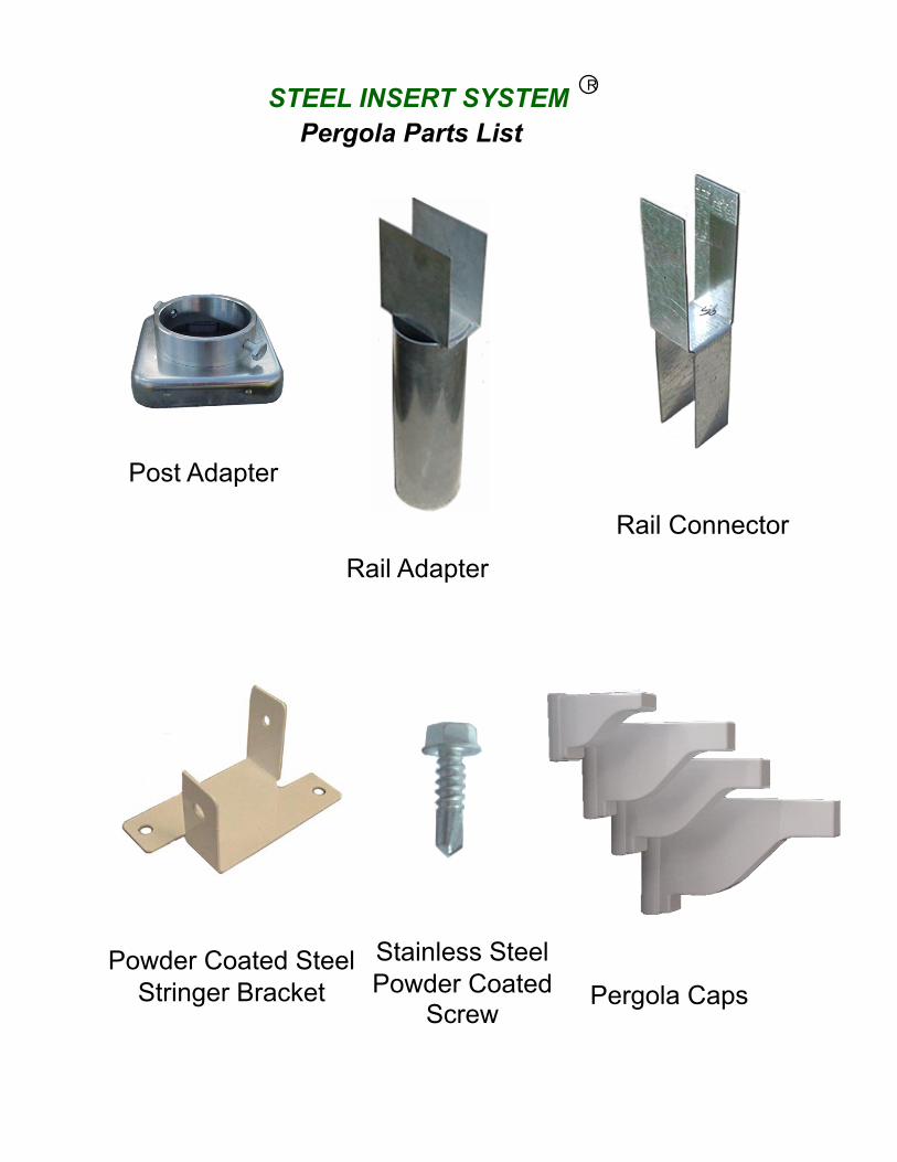
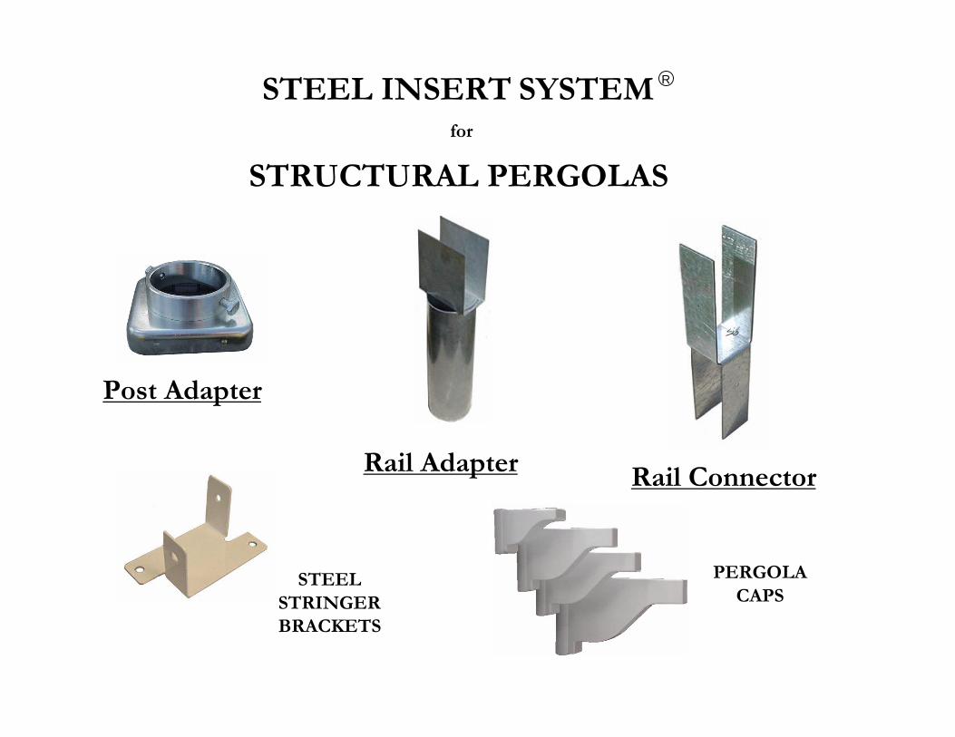
Pergola Parts List
Post Adapter
Powder Coated Steel Stringer Bracket
Rail Adapter
Rail Connector
Stainless Steel Powder Coated
Screw Pergola Caps
STEEL INSERT SYSTEM R
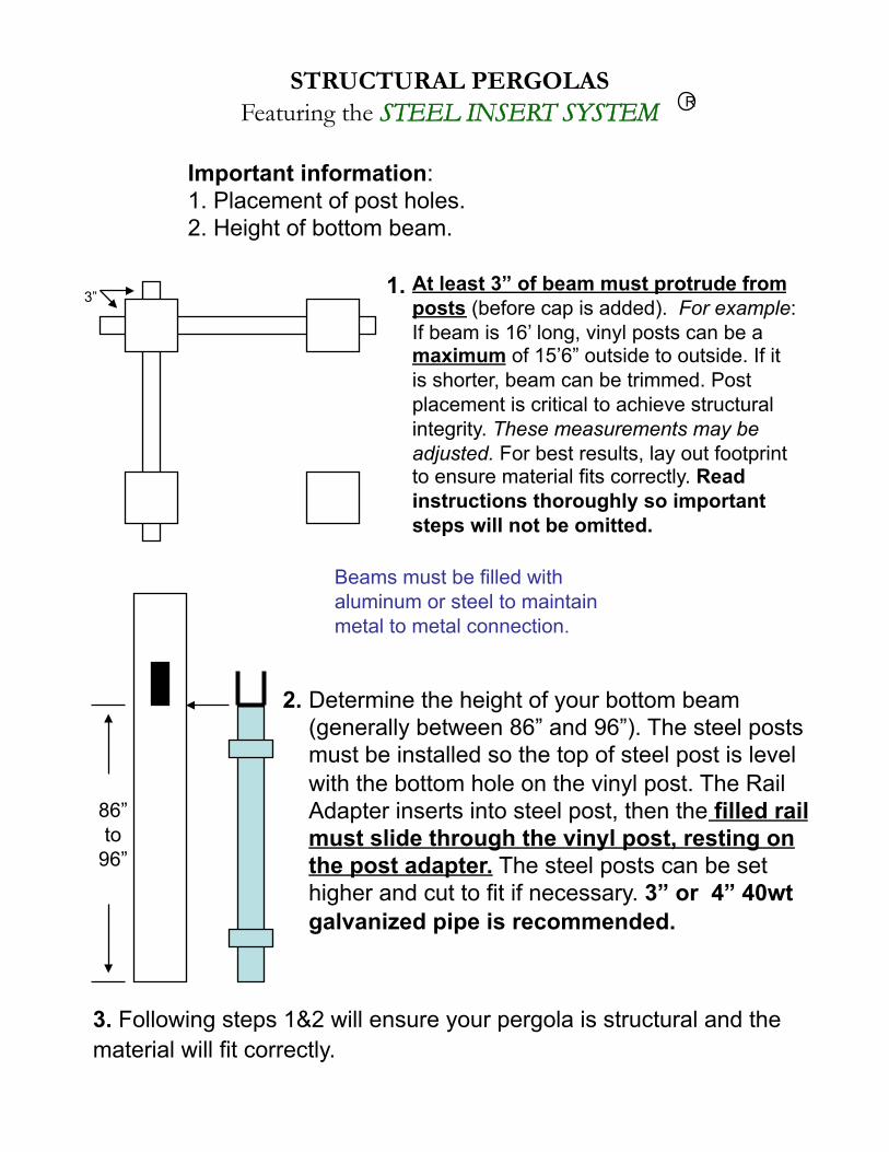
Important information: 1. Placement of post holes. 2. Height of bottom beam.
At least 3” of beam must protrude from posts (before cap is added). For example: If beam is 16’ long, vinyl posts can be a maximum of 15’6” outside to outside. If it is shorter, beam can be trimmed. Post placement is critical to achieve structural integrity. These measurements may be adjusted. For best results, lay out footprint to ensure material fits correctly. Read instructions thoroughly so important steps will not be omitted.
Determine the height of your bottom beam (generally between 86” and 96”). The steel posts must be installed so the top of steel post is level with the bottom hole on the vinyl post. The Rail Adapter inserts into steel post, then the filled rail must slide through the vinyl post, resting on the post adapter. The steel posts can be set higher and cut to fit if necessary. 3” or 4” 40wt galvanized pipe is recommended.
1.
2.
3. Following steps 1&2 will ensure your pergola is structural and the material will fit correctly.
86” to
96”
STRUCTURAL PERGOLAS Featuring the STEEL INSERT SYSTEM
3”
Beams must be filled with aluminum or steel to maintain metal to metal connection.
R
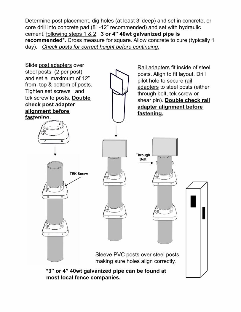
Determine post placement, dig holes (at least 3’ deep) and set in concrete, or core drill into concrete pad (8” -12” recommended) and set with hydraulic cement, following steps 1 & 2. 3 or 4” 40wt galvanized pipe is recommended*. Cross measure for square. Allow concrete to cure (typically 1 day). Check posts for correct height before continuing.
Slide post adapters over steel posts (2 per post) and set a maximum of 12” from top & bottom of posts. Tighten set screws and tek screw to posts. Double check post adapter alignment before fastening.
Rail adapters fit inside of steel posts. Align to fit layout. Drill pilot hole to secure rail adapters to steel posts (either through bolt, tek screw or shear pin). Double check rail adapter alignment before fastening.
Sleeve PVC posts over steel posts, making sure holes align correctly.
*3” or 4” 40wt galvanized pipe can be found at most local fence companies.
TEK Screw
ThroughBolt
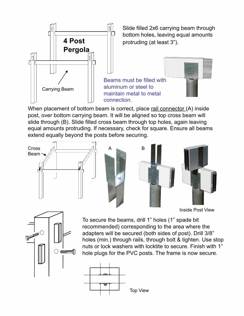
Slide filled 2x6 carrying beam through bottom holes, leaving equal amounts protruding (at least 3”).
To secure the beams, drill 1” holes (1” spade bit recommended) corresponding to the area where the adapters will be secured (both sides of post). Drill 3/8” holes (min.) through rails, through bolt & tighten. Use stop nuts or lock washers with locktite to secure. Finish with 1” hole plugs for the PVC posts. The frame is now secure.
When placement of bottom beam is correct, place rail connector (A) inside post, over bottom carrying beam. It will be aligned so top cross beam will slide through (B). Slide filled cross beam through top holes, again leaving equal amounts protruding. If necessary, check for square. Ensure all beams extend equally beyond the posts before securing.
Cross Beam
Carrying Beam
Inside Post View
A B
4 Post Pergola
Top View
Beams must be filled with aluminum or steel to maintain metal to metal connection.
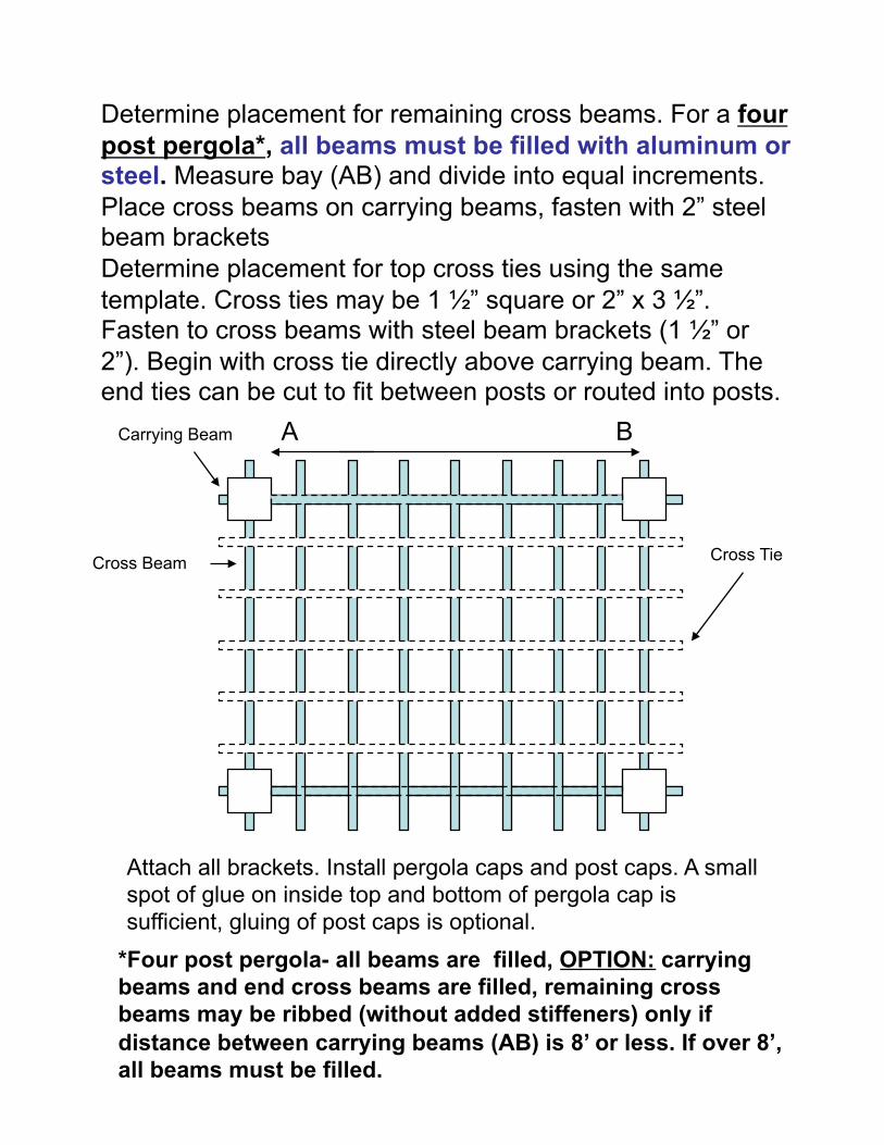
Determine placement for top cross ties using the same template. Cross ties may be 1 ½” square or 2” x 3 ½”. Fasten to cross beams with steel beam brackets (1 ½” or 2”). Begin with cross tie directly above carrying beam. The end ties can be cut to fit between posts or routed into posts.
Determine placement for remaining cross beams. For a four post pergola*, all beams must be filled with aluminum or steel. Measure bay (AB) and divide into equal increments. Place cross beams on carrying beams, fasten with 2” steel beam brackets
A B
Attach all brackets. Install pergola caps and post caps. A small spot of glue on inside top and bottom of pergola cap is sufficient, gluing of post caps is optional.
Carrying Beam
Cross Beam Cross Tie
*Four post pergola- all beams are filled, OPTION: carrying beams and end cross beams are filled, remaining cross beams may be ribbed (without added stiffeners) only if distance between carrying beams (AB) is 8’ or less. If over 8’, all beams must be filled.
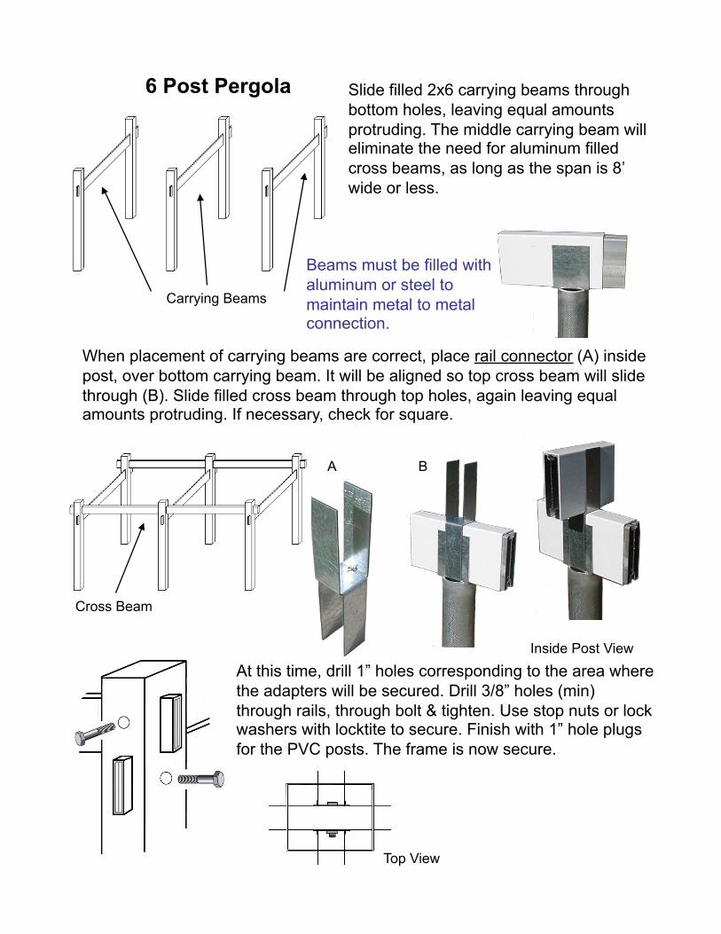
Slide filled 2x6 carrying beams through bottom holes, leaving equal amounts protruding. The middle carrying beam will eliminate the need for aluminum filled cross beams, as long as the span is 8’ wide or less.
At this time, drill 1” holes corresponding to the area where the adapters will be secured. Drill 3/8” holes (min) through rails, through bolt & tighten. Use stop nuts or lock washers with locktite to secure. Finish with 1” hole plugs for the PVC posts. The frame is now secure.
When placement of carrying beams are correct, place rail connector (A) inside post, over bottom carrying beam. It will be aligned so top cross beam will slide through (B). Slide filled cross beam through top holes, again leaving equal amounts protruding. If necessary, check for square.
Inside Post View
A B
6 Post Pergola
Carrying Beams
Cross Beam
Beams must be filled with aluminum or steel to maintain metal to metal connection.
Top View
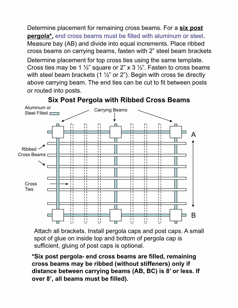
Determine placement for top cross ties using the same template. Cross ties may be 1 ½” square or 2” x 3 ½”. Fasten to cross beams with steel beam brackets (1 ½” or 2”). Begin with cross tie directly above carrying beam. The end ties can be cut to fit between posts or routed into posts.
Determine placement for remaining cross beams. For a six post pergola*, end cross beams must be filled with aluminum or steel. Measure bay (AB) and divide into equal increments. Place ribbed cross beams on carrying beams, fasten with 2” steel beam brackets
A
B
Attach all brackets. Install pergola caps and post caps. A small spot of glue on inside top and bottom of pergola cap is sufficient, gluing of post caps is optional.
Carrying Beams
Ribbed Cross Beams
Cross Ties
*Six post pergola- end cross beams are filled, remaining cross beams may be ribbed (without stiffeners) only if distance between carrying beams (AB, BC) is 8’ or less. If over 8’, all beams must be filled).
Six Post Pergola with Ribbed Cross Beams Aluminum or Steel Filled
STEEL INSERT SYSTEM
Post Adapter
Rail ConnectorRail Adapter
STRUCTURAL PERGOLASfor
PERGOLA CAPS
STEEL STRINGER BRACKETS
R
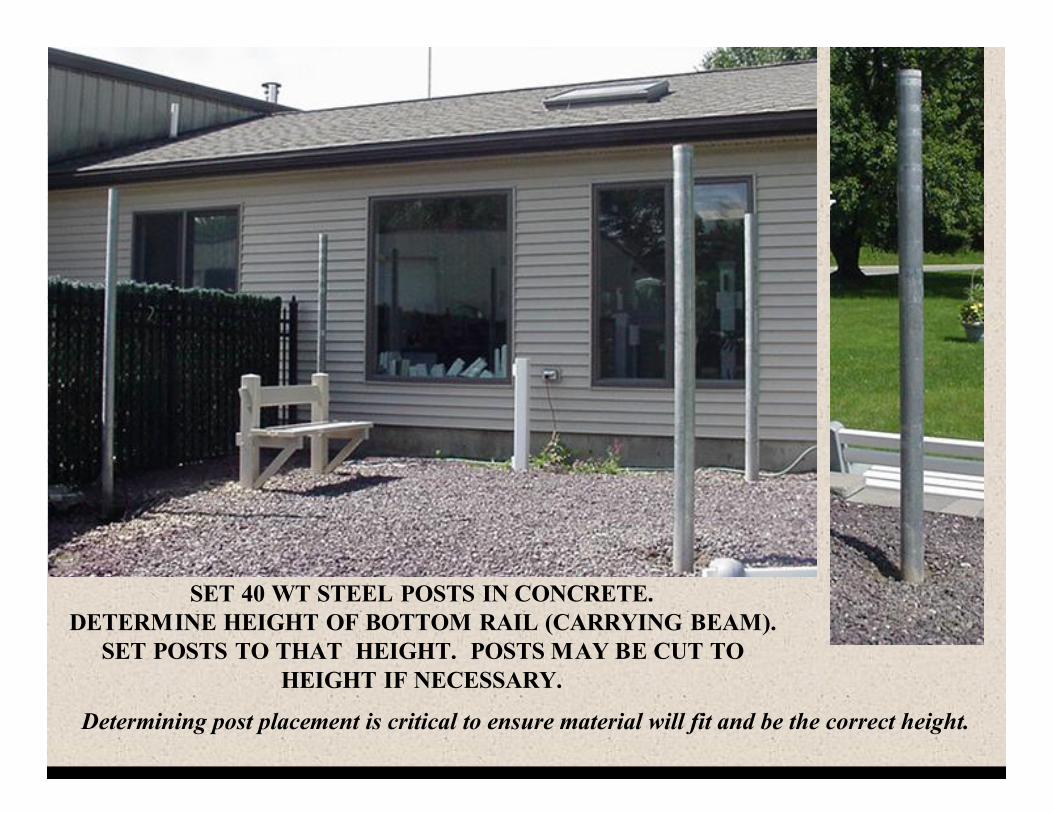
SET 40 WT STEEL POSTS IN CONCRETE. DETERMINE HEIGHT OF BOTTOM RAIL (CARRYING BEAM).
SET POSTS TO THAT HEIGHT. POSTS MAY BE CUT TO HEIGHT IF NECESSARY.
Determining post placement is critical to ensure material will fit and be the correct height.
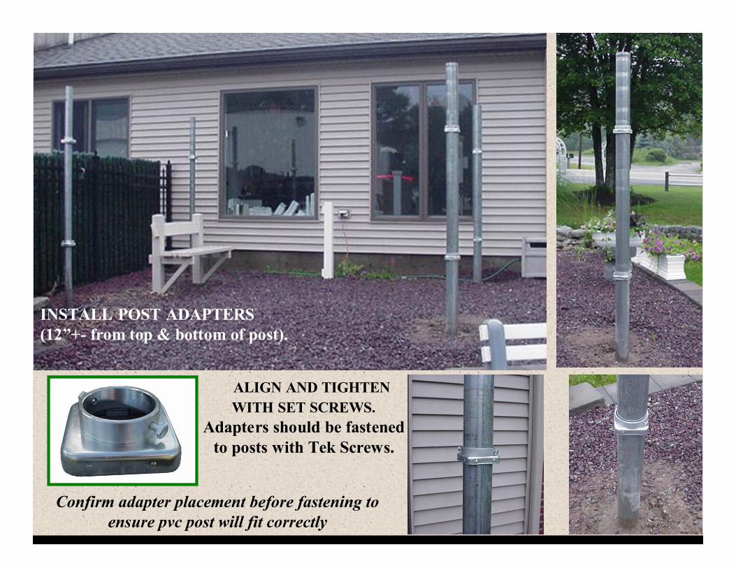
Confirm adapter placement before fastening to ensure pvc post will fit correctly
ALIGN AND TIGHTEN WITH SET SCREWS.
Adapters should be fastened to posts with Tek Screws.
INSTALL POST ADAPTERS (12”+- from top & bottom of post).
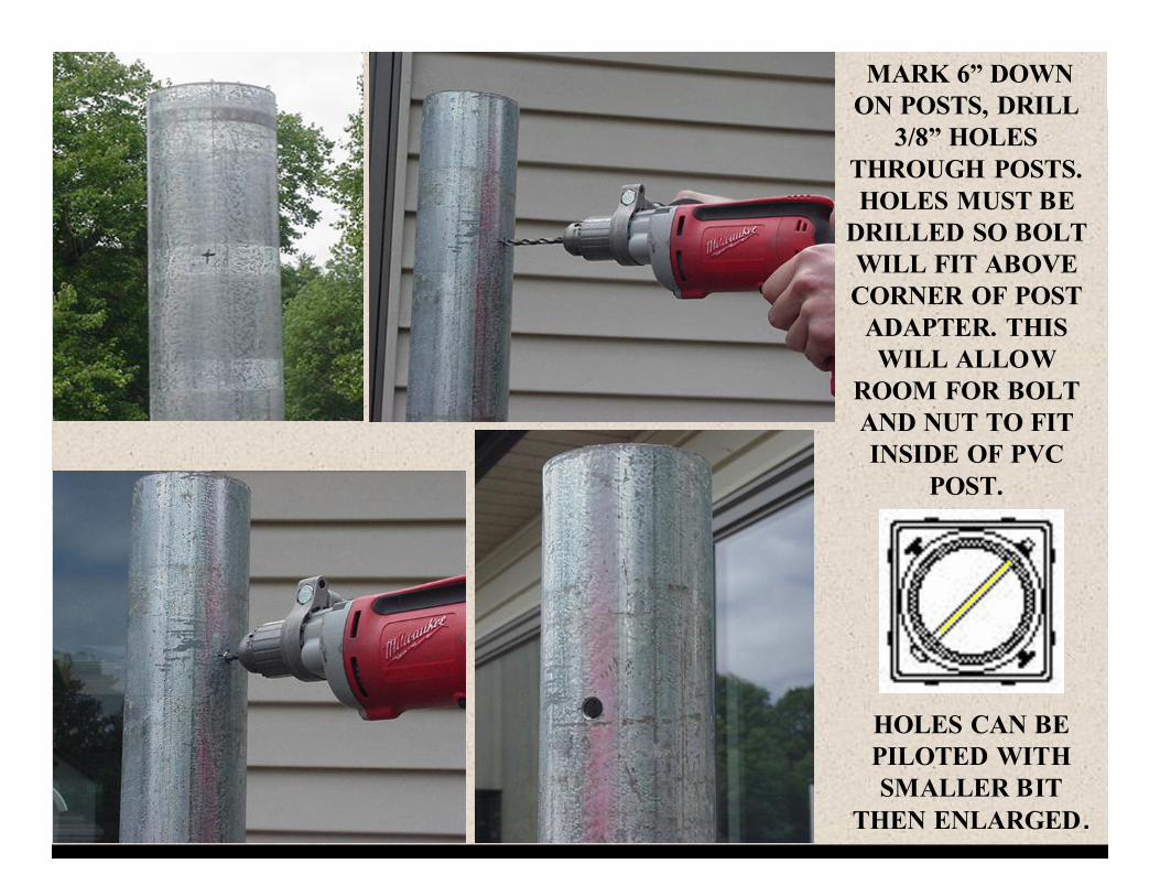
MARK 6” DOWN ON POSTS, DRILL
3/8” HOLES THROUGH POSTS. HOLES MUST BE
DRILLED SO BOLT WILL FIT ABOVE CORNER OF POST
ADAPTER. THIS WILL ALLOW
ROOM FOR BOLT AND NUT TO FIT INSIDE OF PVC
POST.
HOLES CAN BE PILOTED WITH SMALLER BIT
THEN ENLARGED .
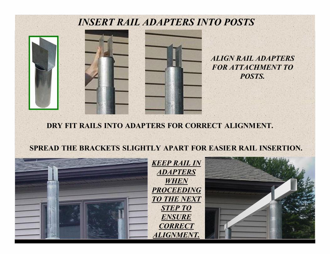
ALIGN RAIL ADAPTERS FOR ATTACHMENT TO
POSTS.
SPREAD THE BRACKETS SLIGHTLY APART FOR EASIER RAIL INSERTION.
DRY FIT RAILS INTO ADAPTERS FOR CORRECT ALIGNMENT.
INSERT RAIL ADAPTERS INTO POSTS
KEEP RAIL IN ADAPTERS
WHEN PROCEEDING TO THE NEXT
STEP TO ENSURE
CORRECT ALIGNMENT.
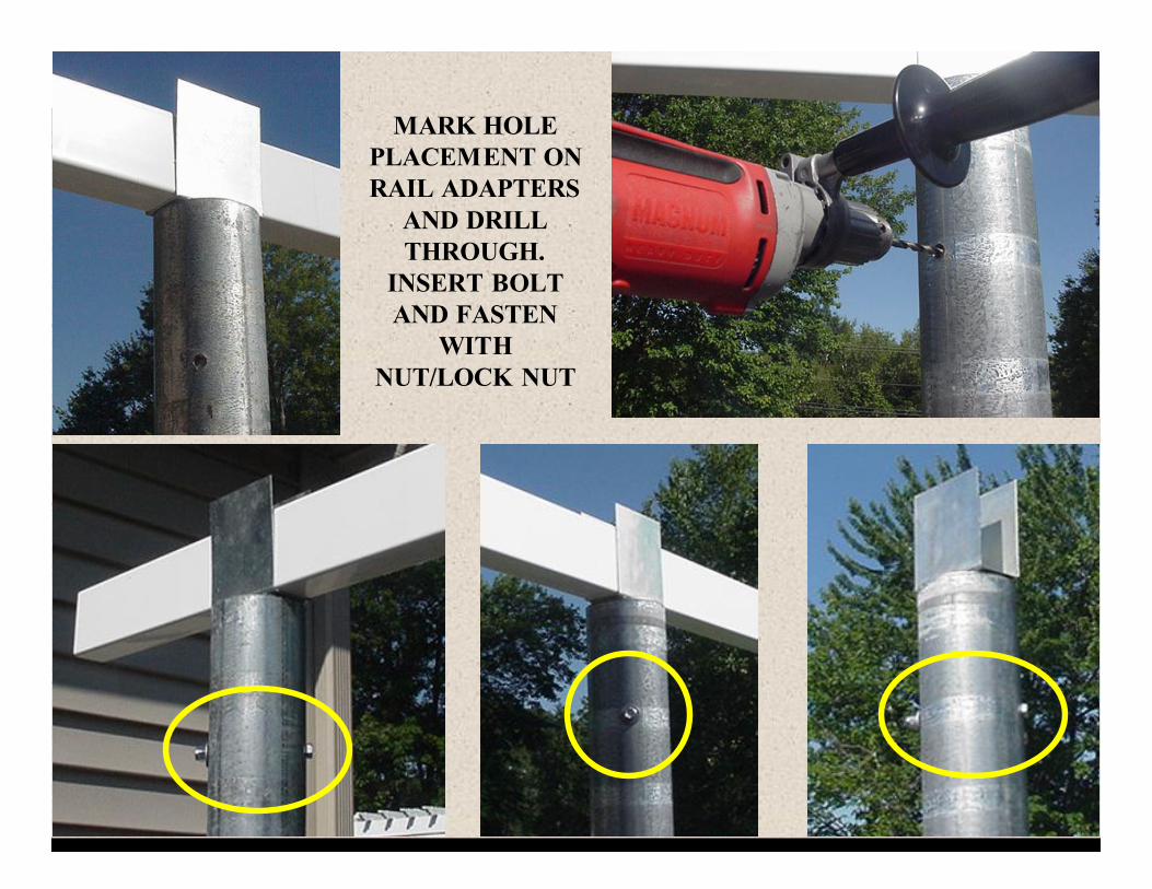
MARK HOLE PLACEMENT ON RAIL ADAPTERS
AND DRILL THROUGH.
INSERT BOLT AND FASTEN
WITH NUT/LOCK NUT
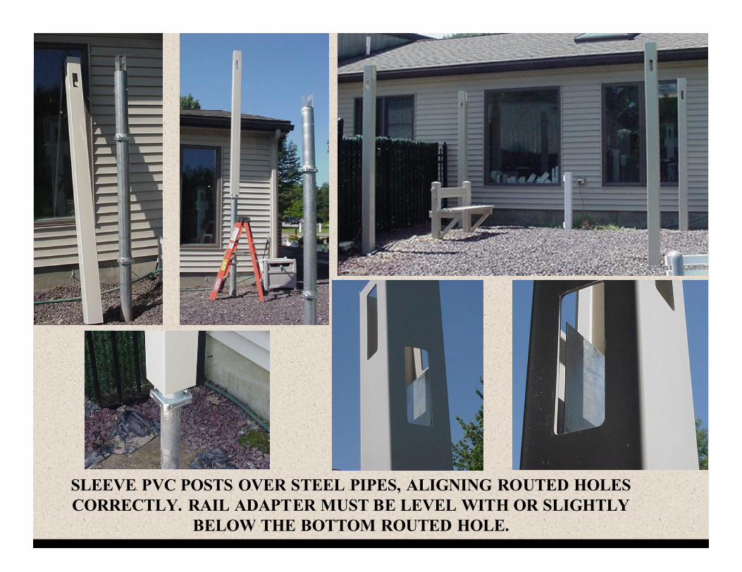
SLEEVE PVC POSTS OVER STEEL PIPES, ALIGNING ROUTED HOLES CORRECTLY. RAIL ADAPTER MUST BE LEVEL WITH OR SLIGHTLY
BELOW THE BOTTOM ROUTED HOLE.
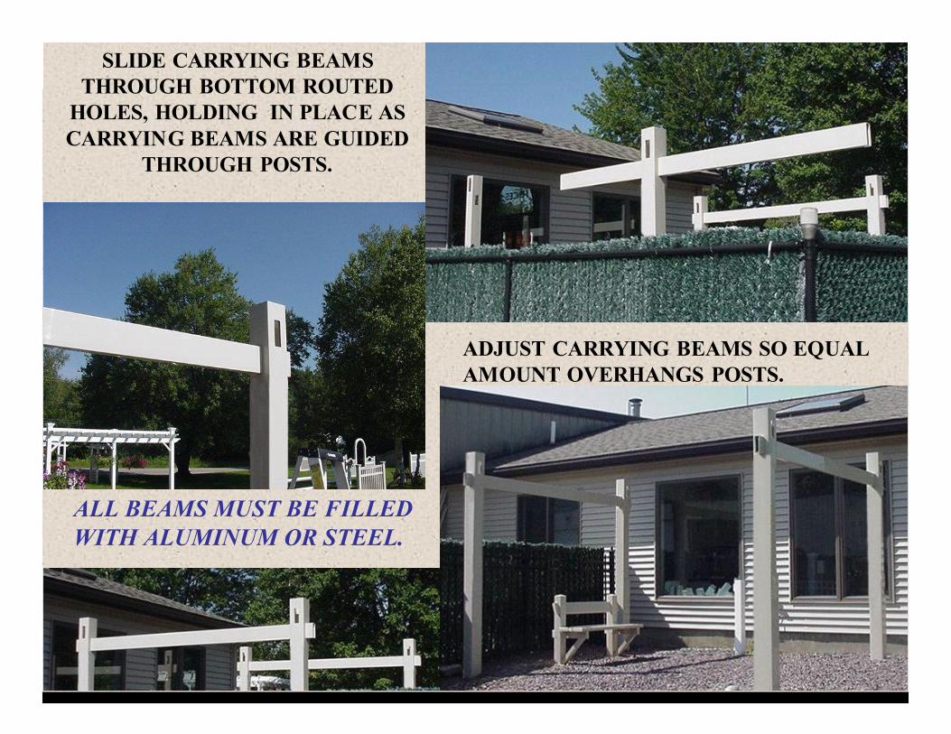
SLIDE CARRYING BEAMS THROUGH BOTTOM ROUTED
HOLES, HOLDING IN PLACE AS CARRYING BEAMS ARE GUIDED
THROUGH POSTS.
ADJUST CARRYING BEAMS SO EQUAL AMOUNT OVERHANGS POSTS.
ALL BEAMS MUST BE FILLED WITH ALUMINUM OR STEEL.
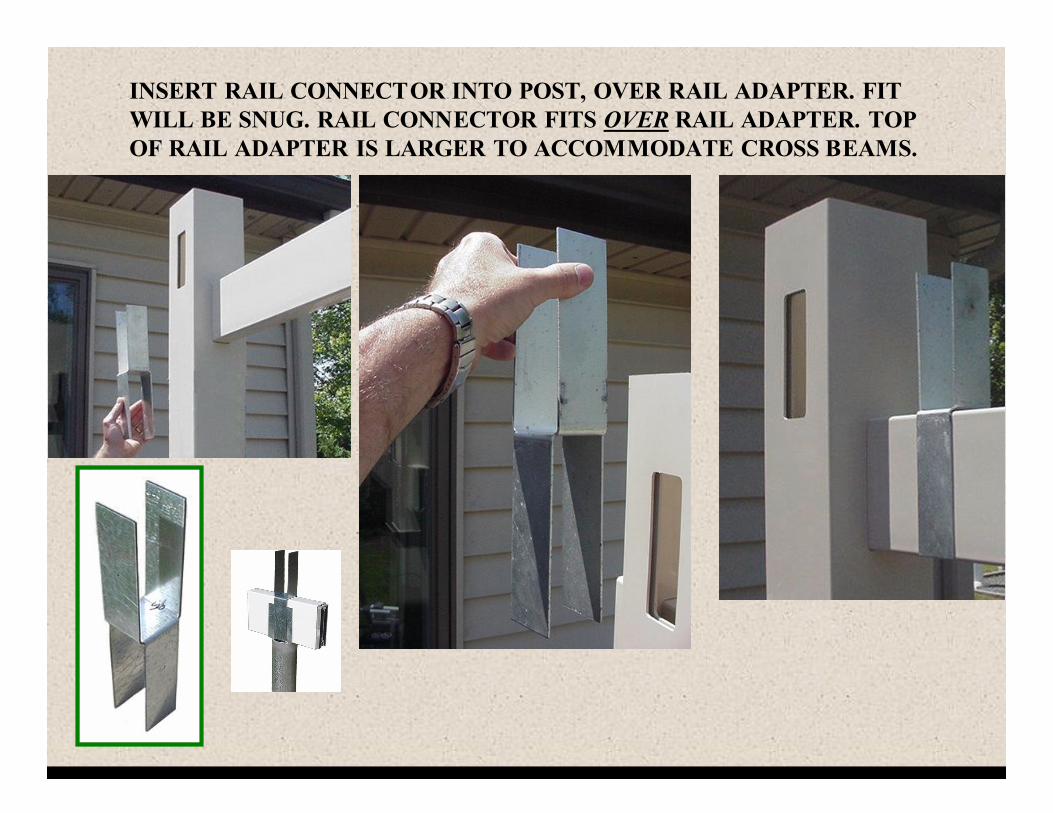
INSERT RAIL CONNECTOR INTO POST, OVER RAIL ADAPTER. FIT WILL BE SNUG. RAIL CONNECTOR FITS OVER RAIL ADAPTER. TOP OF RAIL ADAPTER IS LARGER TO ACCOMMODATE CROSS BEAMS.
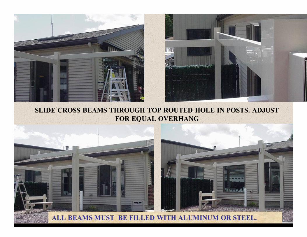
SLIDE CROSS BEAMS THROUGH TOP ROUTED HOLE IN POSTS. ADJUST FOR EQUAL OVERHANG
ALL BEAMS MUST BE FILLED WITH ALUMINUM OR STEEL.
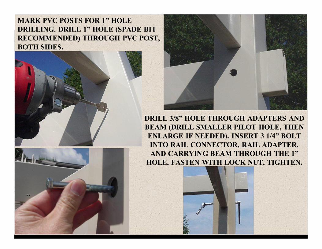
MARK PVC POSTS FOR 1” HOLE DRILLING. DRILL 1” HOLE (SPADE BIT RECOMMENDED) THROUGH PVC POST, BOTH SIDES.
DRILL 3/8” HOLE THROUGH ADAPTERS AND BEAM (DRILL SMALLER PILOT HOLE, THEN ENLARGE IF NEEDED). INSERT 3 1/4” BOLT INTO RAIL CONNECTOR, RAIL ADAPTER, AND CARRYING BEAM THROUGH THE 1”
HOLE, FASTEN WITH LOCK NUT, TIGHTEN.
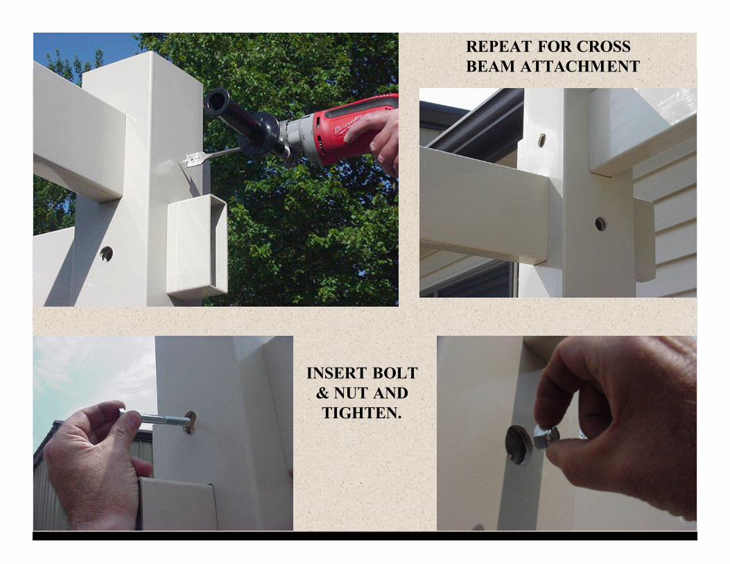
REPEAT FOR CROSS BEAM ATTACHMENT
INSERT BOLT & NUT AND TIGHTEN.
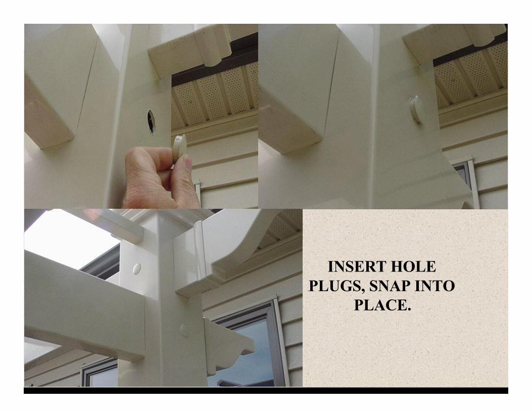
INSERT HOLE PLUGS, SNAP INTO
PLACE.
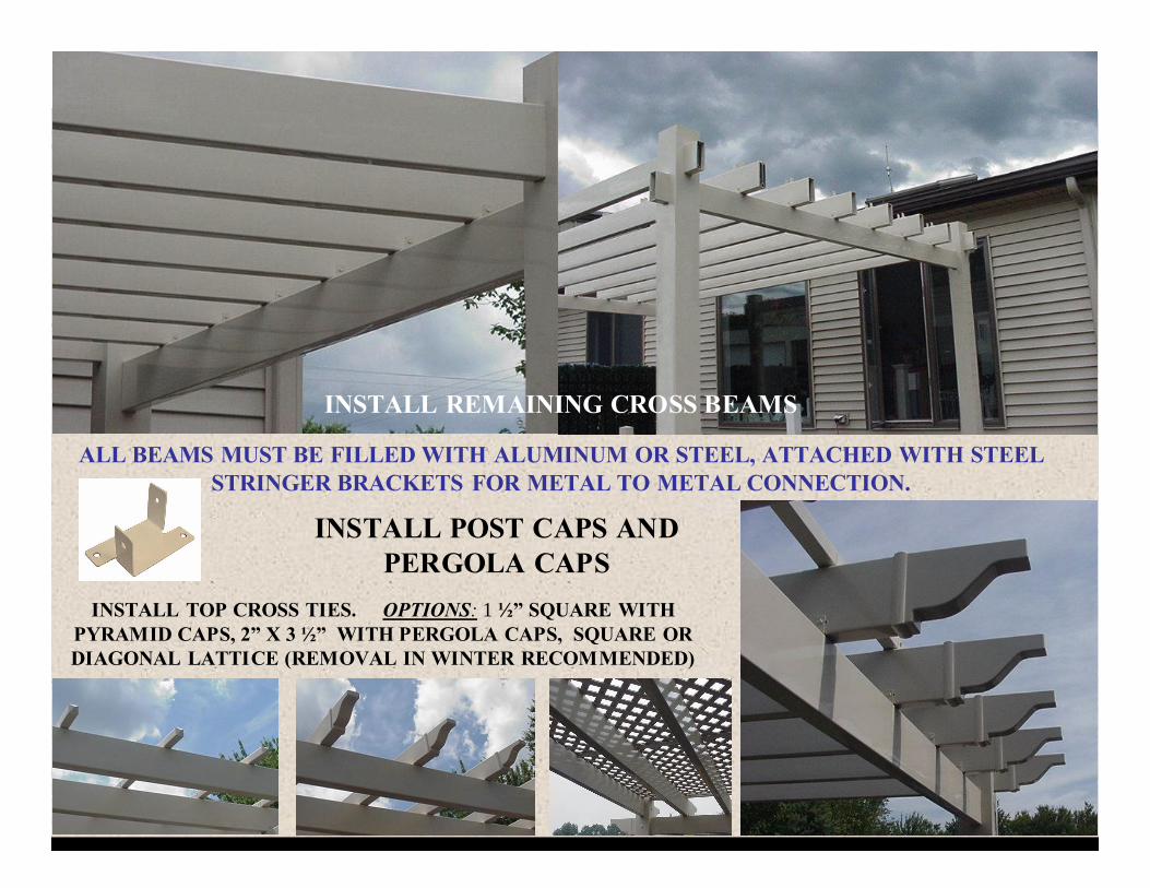
ALL BEAMS MUST BE FILLED WITH ALUMINUM OR STEEL, ATTACHED WITH STEEL STRINGER BRACKETS FOR METAL TO METAL CONNECTION.
INSTALL REMAINING CROSS BEAMS
INSTALL POST CAPS AND PERGOLA CAPS
INSTALL TOP CROSS TIES. OPTIONS: 1 ½” SQUARE WITH PYRAMID CAPS, 2” X 3 ½” WITH PERGOLA CAPS, SQUARE OR DIAGONAL LATTICE (REMOVAL IN WINTER RECOMMENDED)