Embed Size (px)
Citation preview
STEEL BUILDINGS IN EUROPE
Single-Storey Steel Buildings
Part 7: Fire Engineering

Single-Storey Steel Buildings
Part 7: Fire Engineering

7 - ii
Part 7: Fire Engineering
7 - iii
FOREWORD
This publication is the seventh part of the design guide, Single-Storey Steel Buildings.
The 11 parts in the Single-Storey Steel Buildings guide are:
Part 1: Architect’s guide
Part 2: Concept design
Part 3: Actions
Part 4: Detailed design of portal frames
Part 5: Detailed design of trusses
Part 6: Detailed design of built up columns
Part 7: Fire engineering
Part 8: Building envelope
Part 9: Introduction to computer software
Part 10: Model construction specification
Part 11: Moment connections
Single-Storey Steel Buildings is one of two design guides. The second design guide is Multi-Storey Steel Buildings.
The two design guides have been produced in the framework of the European project “Facilitating the market development for sections in industrial halls and low rise buildings (SECHALO) RFS2-CT-2008-0030”.
The design guides have been prepared under the direction of Arcelor Mittal, Peiner Träger and Corus. The technical content has been prepared by CTICM and SCI, collaborating as the Steel Alliance.

Part 7: Fire Engineering
7 - iv
Part 7: Fire Engineering
7 - v
Contents Page No
FOREWORD iii
SUMMARY vi
1 INTRODUCTION 1
2 FIRE RISKS IN SINGLE-STOREY BUILDINGS 2 2.1 Fire safety objectives 2 2.2 Fire risk analysis 2 2.3 Main requirements of current fire regulations 3
3 PRACTICAL FIRE ENGINEERING OPTIONS IN THE EUROCODES 6 3.1 Current design approaches 6 3.2 Fire analysis 7 3.3 Heat transfer analysis 8 3.4 Structural analysis 8
4 GUIDANCE ON APPROPRIATE FIRE ENGINEERING SOLUTIONS 10 4.1 Field of application of different design methods 10 4.2 Choice of optimum design approach 11
5 DIRECT USE OF SIMPLE ENGINEERING OPTIONS FOR USE BY NON SPECIALISTS 12 5.1 Fire models 12 5.2 Thermal Models 16 5.3 Structural Models 21 5.4 Specific design rules for single-storey buildings 31 5.5 Simplified design methods 33 5.6 Design recommendations 37
6 GUIDANCE ON THE USE OF MORE ADVANCED SOLUTIONS 47 6.1 Fire models 47 6.2 Thermal Models 50 6.3 Structural models 51
REFERENCES 56
APPENDIX A German fire safety procedure for single-storey industrial and commercial buildings 57
Part 7: Fire Engineering
7 - vi
SUMMARY
This document provides guidance for the fire design of single-storey steel building structures. It contains detailed information to allow engineers and designers to be more familiar with the current design approaches and calculation models, which can be applied not only to meet the prescriptive requirements but also to develop the performance-based fire safety design. The design methods introduced in the guide, ranging from simple design rules to more sophisticated calculation models, are derived from EN 1993-1-2 and 1994-1-2. They cover both steel and composite structures (unprotected or protected). In addition, some specific design rules are given, allowing simple verification of whether the behaviour of the steel structure of single-storey industrial buildings in fire situation fulfils the safety objectives on the basis of performance-based requirement.
Part 7: Fire Engineering
7 - 1
1 INTRODUCTION
Due to the particularities of single-storey buildings, the life safety objective in case of fire can be met easily without onerous fire resistance requirement for the structure. However, other safety objectives have to be taken into account if the collapse of these buildings or a part of them may be accepted. In consequence, many European fire safety building regulations are moving toward acceptance of alternative fire safety engineering designs. Prescriptive rules can then be replaced with performance based requirements, such as adequate fire behaviour of the structure, aimed at satisfying fire safety objectives that include life safety of people (occupants and fire-fighters), protection of environment, property protection and business continuity. Benefits and successful application of the performance-based approach to building fire safety designs have already been well demonstrated for single-storey buildings, especially where fire resistance was required, allowing in some cases more innovative, cost effective and safer solutions to be adopted.
To help the structural fire design of buildings, a new set of European Standards has been developed, the Eurocodes. The Parts of the Eurocodes that are relevant to the fire design of single-storey building consist of EN 1991-1-2[1] (which includes principal concepts and rules necessary for describing thermal and mechanical actions on structures exposed to fire) and Parts of material –specific Eurocodes dealing with the fire design of structures, such as EN 1993-1-2,[2], related to steel structures and EN 1994-1-2[3] related to composite steel and concrete structures.
The fire parts of Eurocodes provide at present a wide range of calculation methods. They allow engineers to follow either a prescriptive approach to meet the fire safety requirements, as specified in national building regulations, or to carry out on the basis of performance-based rules, a fire safety engineering design that involves in general more complex computational analysis and provides more accurate answers to fire safety objectives.
The present guide provides an overview of the current design methods available for evaluating the fire performance of single-storey buildings composed of either steel or composite structure as well as their application fields. Simple calculations methods, easy to use, and more advanced calculations models are dealt with separately. Moreover, to allow quick assessment, simple design rules are given to assess quickly whether the structural behaviour of steel structures of storage and industrial buildings fulfils the fire safety objectives required by the fire safety regulations for industrial buildings.
This guide aims also to help the engineer to understand more clearly the different calculation methodologies and to carry out the structural fire design of single-storey building according to the Eurocodes, from a relatively simple analysis of single members under standard fire conditions to a more complex analysis under real fire conditions.
Part 7: Fire Engineering
7 - 2
2 FIRE RISKS IN SINGLE-STOREY BUILDINGS
2.1 Fire safety objectives The primary objective of most fire safety regulations is to ensure the protection of life (building occupants and fire fighters), environment and to some extent property (building contents and building itself). Through a lot of measures including a combination of active and passive fire protection systems, the objectives are:
To reduce and prevent the incidence of fire by controlling fire hazards in the building.
To provide safe escape routes for evacuation of building occupants.
To prevent fire spread from the fire compartment to others parts of the building and to neighbouring buildings.
To ensure that the building remains structurally stable for a period of time sufficient to evacuate the occupants and for the fire-fighters to rescue occupants, if necessary.
2.2 Fire risk analysis Single-storey buildings used as factories, warehouses or commercial centres constitute a very common type of steel construction today. In the specific case of warehouses, according to the storage arrangement (including free standing storage, palletised rack storage, post-pallet storage or storage with solid or slatted shelves) and the combustibility of materials being stored, fire may develop very quickly and then might endanger occupants long enough before the structural collapse of the building. Indeed, fire growth may be extremely important, as the upward flame propagation is usually very rapid. Vertical and horizontal shafts formed between adjacent pallets and racking behave as chimneys, which increase the spread of flames up to the roof. The smoke quickly forms a hot layer under the roof and then descends progressively with fire development. Obviously, the rate at which this occurs varies according to the combustible contents and the building arrangement. In unventilated conditions, single-storey buildings can become smoke-logged in few minutes. Although the smoke is largely made up of ‘entrained’ air, it contains enough toxic substances and asphyxiates to incapacitate or kill within minutes people exposed to them. Moreover, the hot smoke layer will also radiate high heat flux to people escaping from fire area. A hot gas layer at 500°C leads to a heat flux of about 20 kW/m² (corresponding to the radiant energy emitted by a blackbody at the temperature of 500°C) and, under such thermal conditions, skin burn will occur after only a few seconds4. Generally, it is agreed that the tenability threshold is 2.5 kW/m2, which is much lower than heat flux needed to lead to the failure of structural members. Consequently, buildings will survive longer than occupants and the structural collapse of steel structures of single-storey buildings generally does not provide additional threat to people escaping from the fire area.
Part 7: Fire Engineering
7 - 3
Regarding fire service operations, it is commonly accepted that fire-fighters should not enter a single-storey building because of fast fire growth. Usually they are forced to fight the fire from outside, covering neighbouring walls with water. Hazard in this case for fire-fighters is then reduced to zero in the event of structural collapse since it occurs at a level of temperature at which fire-fighters can not withstand (provided that the progressive collapse, in the case of compartmented buildings, and the collapse of the structure toward outside do not occur[5,6]). In the event of, at the beginning of fire, they need to enter within the building to rescue people, they cannot last within the building after the heat flux is more than 7 kW/m², which is also very far for the risk of collapse of the structure.
For these reasons, an increase of the intrinsic fire resistance of single-storey buildings is unnecessary. However, the overall stability of the structure and the stability of fire walls need to be accurately considered, to avoid any progressive collapse. A single-storey building undergoes progressive collapse when local failure of the heated part of the structure leads for the failure of adjoining cold structures. In addition, to provide a safe situation to fire-fighters located around the building, the structure of single-storey building (including façade elements) must collapse towards the inside of the building.
Many National Regulations have taken into account previous remarks for industrial single-storey buildings as well as for public buildings by not requiring any fire resistance rating for such works but introducing specific safety requirements in terms of overall structural behaviour and concentrating requirements on egress facilities and early fire detection and/or suppression.
With regards to other single-storey buildings with relatively low fire loads, the risk of life in the event of fire is reduced as egress of occupants and fire-ground operations are straightforward.
2.3 Main requirements of current fire regulations 2.3.1 Fire resistance of structural members
Despite the comments above, fire resistance ratings are sometimes required for the structure of single-storey buildings[7].
The fire resistance is expressed as the time during which a building element can withstand exposure to fire without losing its function (load-bearing elements or separating element). Usually, building elements are classified using three performance criterion:
The load bearing capacity, R, which is the ability for a load-bearing element to resist a fire without losing its structural stability
The integrity, E, which is the ability of a separating element, when exposed to fire on one side, to prevent the passage through it of flames and hot gases
The insulation, I, is the ability of a separating element, when exposed to fire on one side, to restrict the temperature rise on the unexposed face below specified levels (in general a average value of 140°C).
Part 7: Fire Engineering
7 - 4
In prescriptive fire regulations, required fire resistance for a building element is expressed in terms of the minimum period of time during which the building element would function satisfactorily while subject to the standard fire.
When fire stability requirements are given for single-storey buildings, they usually range from 15 minutes (R15) to 60 minutes (R60), depending on the occupancy class of the building, the provision of sprinklers, the building height and the compartment size.
2.3.2 Compartmentation and building separation
Single-storey building must be subdivided into compartments separated by fire walls when the floor area of the building exceeds the allowed maximum compartment size. Limits on the compartment size may be removed by fitting the building with sprinklers.
The effects providing compartmentation on property loss is that direct damage is confined to the content of the compartment in which the fire starts, reducing the chances of the fire growing large. As regards the life safety, people in other parts of the building can use escape routes to get out safely without being exposed to the smoke or gases from the fire.
When considering fire walls between compartments, fire resistance is generally in the range of REI 60 to REI 120.
Fire spread to neighbouring buildings also needs to be prevented. This is achieved traditionally by sufficient separating distances or façade elements with adequate fire resistance. In the French research project Flumilog, a design method has been recently developed to assess the thermal radiant effects of fires in single-storey storage buildings. The method allows calculation of the safe separating distances, taking into account the main characteristics of the building, such as the building content, the type of façade elements and roof, etc.
2.3.3 Fire suppression
Sprinklers may be required by national fire regulations. In addition to their obvious effect in the reduction of the fire growth, their use leads usually to a reduction of the fire resistance rating required for the structure. They allow also larger fire compartment sizes.
2.3.4 Smoke control systems
National fire regulations may require that smoke control systems are implemented in public buildings, storage building and industrial buildings in order to facilitate escape, by minimising risks of smoke inhalation and injury and to some extend to enable fire-fighters to better see the fire and therefore to extinguish it more speedily and effectively. Smoke control systems help in removing smoke from the fire area, and in limiting the spread of hot gas beneath the roof, which increases the time for the compartment to become smoke-logged, giving people more time to escape safely from the building. This can be achieved by a combination of smoke exhaust systems (mechanical or natural) and screens (which contain the smoke in specific areas).
Part 7: Fire Engineering
7 - 5
2.3.5 Fire detection and fire alarms
Adequate measures are necessary for detecting any outbreak of fire and for alerting the building occupants and the fire department of the occurrence of fire. In small single-storey buildings where all exits are visible, it is likely that any fire will be quickly detected by the occupants and a shout of ‘Fire!’ may be sufficient. In larger single-storey buildings, a simple sounder such as a battery powered alarm or rotary bell may be adequate. In an industrial building, the ambient noise has to be considered, to ensure that the alarm will be heard by the occupants.
2.3.6 Egress facilities
For safe evacuation, appropriate means of escape are needed, such as a proper number and width of emergency exits and proper length, width and height of passages and evacuation accesses. Escape routes in small single-storey buildings generally lead directly to a safe location outside the building; they do not normally require any special treatment. In larger buildings, where travel distances are greater and where the fire is likely to make a single escape routes unusable, an alternative means of escape may be necessary. Consideration of disabled people must also be made
Part 7: Fire Engineering
7 - 6
3 PRACTICAL FIRE ENGINEERING OPTIONS IN THE EUROCODES
3.1 Current design approaches Using the fire parts of Eurocodes[8,9], single-storey buildings can be designed using either the prescriptive approach or the performance-based approach applying fire safety engineering principles[10].
The prescriptive approach is mostly applied to fulfil standard fire resistance requirements usually prescribed in national fire regulations. It gives a safety level that is relatively easy to achieve and implement. However it may be conservative, in requiring the use of important passive fire protection to fulfil the required fire resistance rating. This approach is usually carried out for the design of relatively simple buildings and structures.
As an alternative or when allowed by national regulation, the performance-based approach can allow to assess adequate measures to satisfy a set-out of defined fire safety objectives, such as stated in paragraph 2.1, and the corresponding performance criteria. Using structural fire engineering, engineers can assess the necessary fire resistance to structure in order to avoid the spread of fire and/or to prevent a premature structural collapse. As regards the single-storey buildings, the main structure could be designed to remain stable under fire exposure conditions long enough for the occupants to escape. Such an approach takes into account the severity of fire exposure by appropriate estimations of actual fire loads and fire development parameters, which may be calculated from the building activity.
The performance-based approach provides flexibility when selecting technical solutions to meet the fire safety objectives, but usually requires the use of sophisticated design tools. Engineers and designers using advanced calculations models need to be properly educated in their use and in their limitations. As fire safety engineering allows for highly efficient designs, with little unassigned reserve capacity, an experienced user is required to ensure that appropriate models are used.
Where national fire regulations authorise the performance-based approach, regulatory bodies may require that the fire design is checked by a third party.
The fire performance of a whole structure, or a part of it, is carried out by following, for a given design fire scenario, three successive steps of structural fire engineering[1].
Fire Analysis. To calculate the thermal actions/exposure - Fire models.
Thermal analysis. To determinate the heating rate and temperatures on structural members - Thermal models.
Structural analysis. To calculate the mechanical response of structural members- Structural models.
Part 7: Fire Engineering
7 - 7
Available design methods to evaluate the fire performance of structure are briefly described below. These methods range from simple hand calculations to the use of sophisticated computer models. The overall complexity of the fire safety design will depend on the assumptions and methods adopted to predict each of the three design steps.
3.2 Fire analysis The main objective of the fire modelling is the simulation of the fire development and the prediction of thermal actions (gas temperature, heat flux) on the structural members (in order to determinate, in a following step, the temperature in the structural members).
Although common practice is to represent a fire by a standard fire curve, structural fire design may be based on a design fire that provides more realistic conditions in fire compartment. In this way, parameters such as the magnitude of the fire load, the rate of heat release and the ventilation factor, which play an important role in fire severity, are taken into account. Moreover, the identification of relevant and realistic design fire scenarios is a crucial aspect of the fire safety design. The design fire scenarios used for the analysis of a building fire have to be deduced from all the possible fire scenarios. In most buildings, the number of possible fire scenarios is infinite and need to be reduced. Only ‘credible worst case’ fire scenarios will need to be studied. When the design fire scenarios are chosen, a number of fire models are available to assess the fire severity and calculate the corresponding thermal actions
Different levels of fire models are relevant to the various stages of fire development. When a fire is initiated, it is localised within a compartment and, according to the characteristics of the compartment and of the fire load, it can remain localised or becomes generalised to the whole compartment. In the case of small compartments or compartments with small ventilation openings relative to the size of the compartment, the fire develops into to a fully engulfed fire.
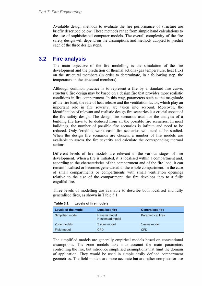
Three levels of modelling are available to describe both localised and fully generalised fires, as shown in Table 3.1.
Table 3.1 Levels of fire models
Levels of the model Localised fire Generalised fire
Simplified model Hasemi model Heskestad model
Parametrical fires
Zone models 2 zone model 1-zone model
Field model CFD CFD
The simplified models are generally empirical models based on conventional assumptions. The zone models take into account the main parameters controlling the fire, but introduce simplified assumptions that limit the domain of application. They would be used in simple easily defined compartment geometries. The field models are more accurate but are rather complex for use
Part 7: Fire Engineering
7 - 8
as a general design tool; they would be required in compartments with complex geometries or with high and irregular ceilings.
Conditions of use will be briefly detailed in Chapter 6.
3.3 Heat transfer analysis Once the thermal actions are calculated, the thermal transfer to the structural elements has to be calculated. Thermal models, which will be used, should be based on the acknowledged principles and assumptions of the theory of heat transfer.
Different modelling can be used according to the assumptions and needs. In the thermal models, there are the analytical rules allowing obtaining an estimation of uniform temperature across-section, mainly for steel elements. There are also advanced calculation methods based on either finite elements or the finite difference method, allowing determination of the 2D or 3D temperature distribution in structural members (through the cross-section and along the length). Advanced models can be applied for any type of structural member analysis in fire design.
Thermal models will be briefly detailed in following chapters.
3.4 Structural analysis From the temperature fields previously obtained in the structural members and from the combination of the mechanical actions loads in case of fire the structural behaviour can be assessed following one of the three possible approaches:
Member analysis, in which each member of the structure will be assessed by considering it fully separated from other members. The connection condition with other members will be replaced by appropriate boundary conditions.
Analysis of parts of the structure, in which a part of the structure will be directly taken into account in the assessment by using appropriate boundary conditions to reflect its links with other parts of the structure
Global structural analysis, in which the whole structure will be used in the assessment
Part 7: Fire Engineering
7 - 9
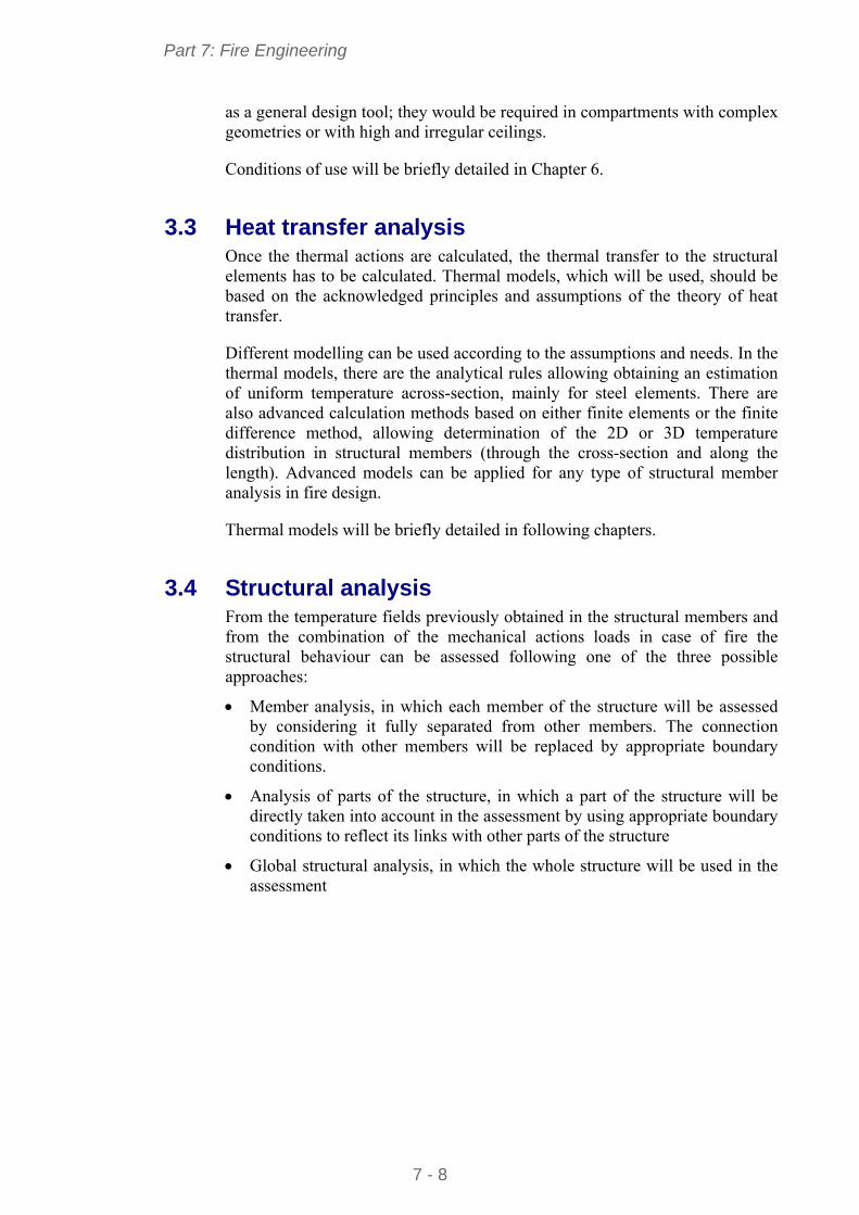
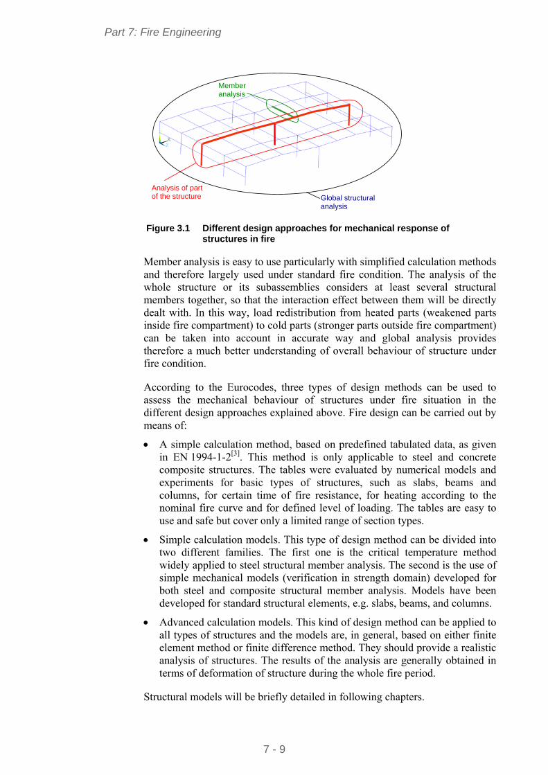
Member analysis
Analysis of part of the structure Global structural
analysis Figure 3.1 Different design approaches for mechanical response of
structures in fire
Member analysis is easy to use particularly with simplified calculation methods and therefore largely used under standard fire condition. The analysis of the whole structure or its subassemblies considers at least several structural members together, so that the interaction effect between them will be directly dealt with. In this way, load redistribution from heated parts (weakened parts inside fire compartment) to cold parts (stronger parts outside fire compartment) can be taken into account in accurate way and global analysis provides therefore a much better understanding of overall behaviour of structure under fire condition.
According to the Eurocodes, three types of design methods can be used to assess the mechanical behaviour of structures under fire situation in the different design approaches explained above. Fire design can be carried out by means of:
A simple calculation method, based on predefined tabulated data, as given in EN 1994-1-2[3]. This method is only applicable to steel and concrete composite structures. The tables were evaluated by numerical models and experiments for basic types of structures, such as slabs, beams and columns, for certain time of fire resistance, for heating according to the nominal fire curve and for defined level of loading. The tables are easy to use and safe but cover only a limited range of section types.
Simple calculation models. This type of design method can be divided into two different families. The first one is the critical temperature method widely applied to steel structural member analysis. The second is the use of simple mechanical models (verification in strength domain) developed for both steel and composite structural member analysis. Models have been developed for standard structural elements, e.g. slabs, beams, and columns.
Advanced calculation models. This kind of design method can be applied to all types of structures and the models are, in general, based on either finite element method or finite difference method. They should provide a realistic analysis of structures. The results of the analysis are generally obtained in terms of deformation of structure during the whole fire period.
Structural models will be briefly detailed in following chapters.
Part 7: Fire Engineering
7 - 10
4 GUIDANCE ON APPROPRIATE FIRE ENGINEERING SOLUTIONS
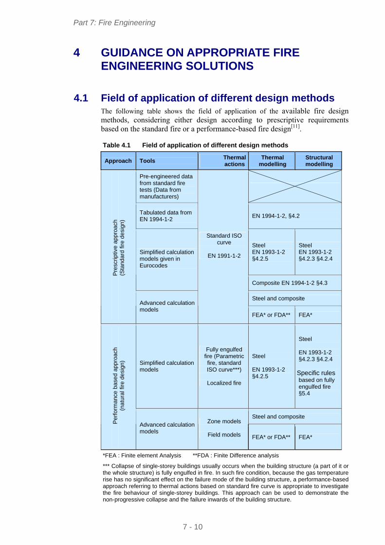
4.1 Field of application of different design methods The following table shows the field of application of the available fire design methods, considering either design according to prescriptive requirements based on the standard fire or a performance-based fire design[11]. Table 4.1 Field of application of different design methods
Approach Tools Thermal actions
Thermal modelling
Structural modelling
Pre-engineered data from standard fire tests (Data from manufacturers)
Tabulated data from EN 1994-1-2
EN 1994-1-2, §4.2
Steel EN 1993-1-2 §4.2.5
Steel EN 1993-1-2 §4.2.3 §4.2.4
Simplified calculation models given in Eurocodes
Composite EN 1994-1-2 §4.3
Steel and composite
Pre
scrip
tive
appr
oach
(S
tand
ard
fire
desi
gn)
Advanced calculation models
Standard ISO curve
EN 1991-1-2
FEA* or FDA** FEA*
Simplified calculation models
Fully engulfed fire (Parametric fire, standard ISO curve***)
Localized fire
Steel EN 1993-1-2 §4.2.5
Steel EN 1993-1-2 §4.2.3 §4.2.4
Specific rules based on fully engulfed fire §5.4
Steel and composite
Per
form
ance
bas
ed a
ppro
ach
(n
atur
al f
ire d
esi
gn)
Advanced calculation models
Zone models
Field models FEA* or FDA** FEA*
*FEA : Finite element Analysis **FDA : Finite Difference analysis
*** Collapse of single-storey buildings usually occurs when the building structure (a part of it or the whole structure) is fully engulfed in fire. In such fire condition, because the gas temperature rise has no significant effect on the failure mode of the building structure, a performance-based approach referring to thermal actions based on standard fire curve is appropriate to investigate the fire behaviour of single-storey buildings. This approach can be used to demonstrate the non-progressive collapse and the failure inwards of the building structure.
Part 7: Fire Engineering
7 - 11
4.2 Choice of optimum design approach The choice of the design approach depends on the type of building (storage building, industrial building, commercial building, etc.), the requirements specified in the corresponding national fire regulation and the acceptance or not by the regulatory authorities of applying a performance-based approach as an alternative to prescriptive rules.
Some suggestions on the choice of fire design approach are given below.
With the diversity of requirement, the most important first step is to answer the following:
What is the required fire resistance rating, if any?
Is it possible to carry-out a performance-based approach?
When a prescriptive approach is to be used (with reference to standard fire design):
It may be appropriate to use simplified calculation models where low fire resistance ratings (R15 or R30) are required for structural members
Advanced calculation models must be used where structural members are not covered by the simplified calculation models. They can also be employed with some economic benefits for steel structure where high fire resistance ratings (higher than R60) are required, reducing the thickness of fire protection on steel members.
Where the performance-based approach is accepted by the regulatory authorities and structural stability is needed:
A performance-based approach is most likely to be beneficial where the structure is unusual and may not be well covered by traditional prescriptive methods
Localised fire protection may be needed, considering the overall behaviour of the whole structure in a real fire, to ensure adequate life safety for the building occupants and firemen.
National fire regulations may require the use of the performance based approach for single-storey buildings with significant fire risks (high fire loads).
National fire regulations may allow a performance-based fire safety design to refer to simple rules and design recommendations for single-storey buildings. Such approaches are given in §5.4 and Appendix A. Other design guidance and recommendations can be found in reference[12].
Active fire protection measures (installation of sprinklers, fire detectors, fire alarms, smoke exhaust systems) and passive fire protection measures (compartmentation, egress facilities, etc.) are usually implemented in buildings in accordance with the requirements in fire national regulations.
Part 7: Fire Engineering
7 - 12
5 DIRECT USE OF SIMPLE ENGINEERING OPTIONS FOR USE BY NON SPECIALISTS
This chapter gives an overview of current easy-to-use ‘simple’ calculation design rules, for assessing the fire resistance of steel and composite steel and concrete structural members.
Specific simple design rules and design recommendations to satisfy specific safety requirements in terms of structural behaviour introduced recently in fire safety regulations of many European countries for single-storey storage and industrial buildings are given. It is noted that these methods are also applicable to other type of single-storey buildings.
5.1 Fire models 5.1.1 Nominal temperature-time curves
EN 1991-1-2[1] provides three standard fire curves, defining arbitrary hot gas temperature-time relationships in which no physical parameters of the fire load or fire compartment are taken into account. The most commonly used relationships in building design and in regulation prescriptions is the standard temperature-time curve (standard ISO fire) which represents a fully developed compartment fire. The second curve, the external fire curve, is intended for façade elements and the third curve is the hydrocarbon fire curve, representing a fire with hydrocarbon or liquid type fuel.
The nominal temperature-time curves are defined as follows:
For standard temperature-time curve (standard ISO fire ):
)18(log34520 10 tg (1)
For the external fire curve:
20)313,0687,01(660 8,332,0g tt ee (2)
For the hydrocarbon fire curve:
20)675,0325,01(1080 5,2167,0g tt ee (3)
where:
θg is the gas temperature in the fire compartment [°C]
t is the time [min]
It is important to note that the previous curves are reference curves. They do not represent the real thermal effect of a fire. The temperatures given by these curves always increase with time, without considering the limited fire load. The standard fire resistance rating required for structural members (expressed in terms of time) does not therefore indicate the actual time for which they will survive in a building fire.
Part 7: Fire Engineering
7 - 13
5.1.2 Parametric fires
Parametric fire models provide a rather simple design method to estimate gas temperature in fire compartment, taking into account in a simplified way the main parameters that influence the fire development, such as the fire compartment size, the fire load (corresponding to the mass of combustible materials in the fire compartment), ventilation conditions (openings) and thermal properties (such as thermal conductivity and specific heat) of the compartment walls and ceilings.
Like nominal temperature-time curves, parametric temperature-time curves provide gas temperature-time relationships for design. They are based on the hypothesis that the temperature is uniform in the compartment, which limits their field of application to post-flashover fires (fires generalised to the whole compartment) in compartments of reasonable dimensions. The predicted fire curve comprises a heating phase represented by an exponential curve up to a maximum temperature, followed by a linearly decreasing cooling phase to a residual temperature that is usually the ambient temperature. The maximum temperature and the corresponding fire duration are the two main parameters affecting the fire behaviour of structural members. Consequently, they were adopted as the governing parameters in the design formulae for the parametric fires.
Such a model is given in Annex A of EN 1991-1-2. It is valid for compartments up to 500 m² of floor area, without openings in the roof, and a maximum compartment height of 4 m, for compartment linings with thermal inertia between 100 and 2200 J/m2s1/2K, for an opening factor in the range 0,02 to 0.20 and for compartments with mainly cellulosic type fire loads. Due to these limitations, the model is mainly used for the office part of single-storey buildings.
Part 7: Fire Engineering
7 - 14
Time
g
max
t*max
heating phase
cooling phase
g=20+1325(1-0,324e-0,2t*-0,2e-1,7t*-0,427e-19t*)
with t*= t.C where t is the time (hours) and )²1160/04.0/(]²b/O[R
Main parameters:
- Wall characteristics : thermal inertia cb
- Opening characteristics: opening factor tv A/hAO
max= g (t*max) = g (tmax . ) (°C)
with tmax = max{ (0.2.10-3 qt,d / O). / O, tlim } (hours)
where tlim is a function of fire growth rate (according to building type):
- tlim =25 min if slow fire growth rate
- tlim =20 min if medium fire growth rate,
- tlim =15 min if fast fire growth rate,
- qt,d is the design value of the load density [MJ/m²]
g = g (t*, t*max, x) (°C)
= max – 625.(t* - t*max.x) if t*max 0,5
= max – 250.(3- t*max).(t* - t*max.x) if 0,5 < t*max 2
= max – 250.(t* - t*max) if t*max > 2
with t*= t. t*max = (0.2.10-3 qt,d / O).
and x is a function of tmax as follows:
x = 1 if tmax > tlim
x = tlim. / t*max if tmax = tlim
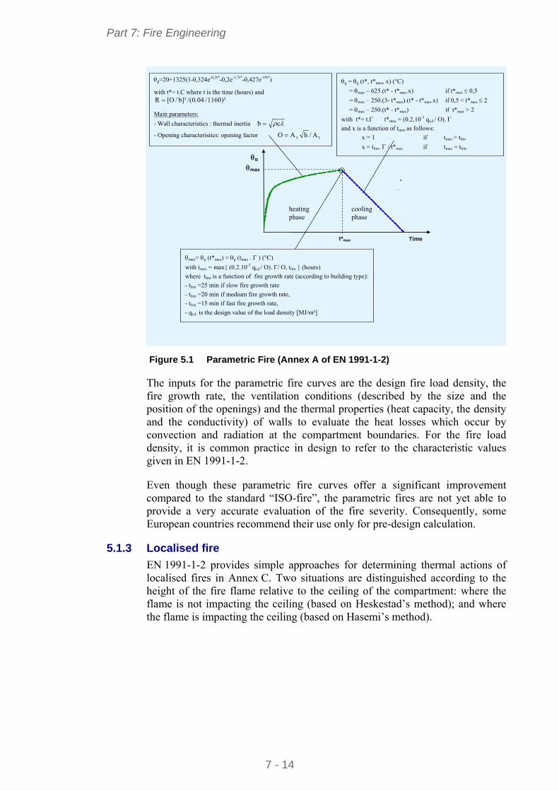
Figure 5.1 Parametric Fire (Annex A of EN 1991-1-2)
The inputs for the parametric fire curves are the design fire load density, the fire growth rate, the ventilation conditions (described by the size and the position of the openings) and the thermal properties (heat capacity, the density and the conductivity) of walls to evaluate the heat losses which occur by convection and radiation at the compartment boundaries. For the fire load density, it is common practice in design to refer to the characteristic values given in EN 1991-1-2.
Even though these parametric fire curves offer a significant improvement compared to the standard “ISO-fire”, the parametric fires are not yet able to provide a very accurate evaluation of the fire severity. Consequently, some European countries recommend their use only for pre-design calculation.
5.1.3 Localised fire
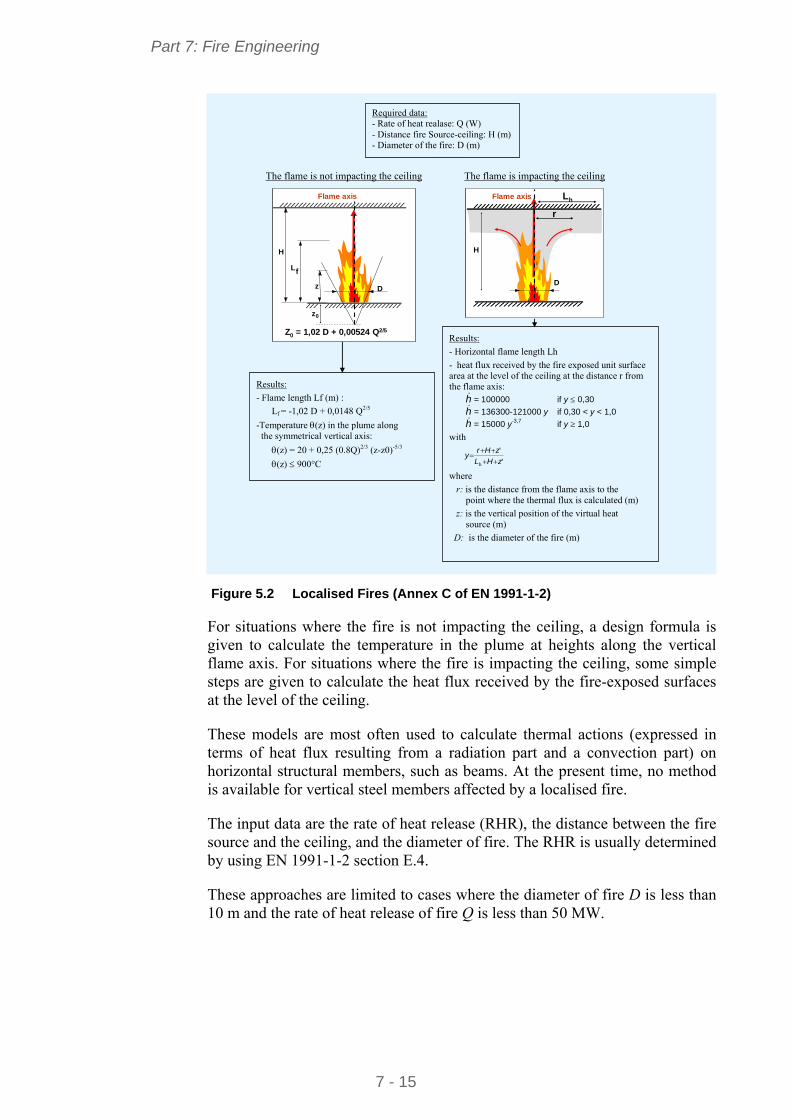
EN 1991-1-2 provides simple approaches for determining thermal actions of localised fires in Annex C. Two situations are distinguished according to the height of the fire flame relative to the ceiling of the compartment: where the flame is not impacting the ceiling (based on Heskestad’s method); and where the flame is impacting the ceiling (based on Hasemi’s method).
Part 7: Fire Engineering
7 - 15
Flame axis
L
z D
f
H
Z0 = 1,02 D + 0,00524 Q2/5
z0
Flame axis
L
z D
f
H
Z0 = 1,02 D + 0,00524 Q2/5
z0
Flame axis Lh
D
H
r
Flame axis Lh
D
H
r
The flame is not impacting the ceiling The flame is impacting the ceiling
Required data: - Rate of heat realase: Q (W) - Distance fire Source-ceiling: H (m) - Diameter of the fire: D (m)
Results:
- Flame length Lf (m) :
Lf = -1,02 D + 0,0148 Q2/5
-Temperature (z) in the plume along the symmetrical vertical axis:
(z) = 20 + 0,25 (0.8Q)2/3 (z-z0)-5/3
(z) 900°C
Results:
- Horizontal flame length Lh
- heat flux received by the fire exposed unit surface area at the level of the ceiling at the distance r from the flame axis: h = 100000 if y 0,30
h = 136300-121000 y if 0,30 < y < 1,0
h = 15000 y-3,7 if y 1,0
with
'
'
h zHL
zHry
where
r: is the distance from the flame axis to the point where the thermal flux is calculated (m)
z: is the vertical position of the virtual heat source (m)
D: is the diameter of the fire (m)
Figure 5.2 Localised Fires (Annex C of EN 1991-1-2)
For situations where the fire is not impacting the ceiling, a design formula is given to calculate the temperature in the plume at heights along the vertical flame axis. For situations where the fire is impacting the ceiling, some simple steps are given to calculate the heat flux received by the fire-exposed surfaces at the level of the ceiling.
These models are most often used to calculate thermal actions (expressed in terms of heat flux resulting from a radiation part and a convection part) on horizontal structural members, such as beams. At the present time, no method is available for vertical steel members affected by a localised fire.
The input data are the rate of heat release (RHR), the distance between the fire source and the ceiling, and the diameter of fire. The RHR is usually determined by using EN 1991-1-2 section E.4.
These approaches are limited to cases where the diameter of fire D is less than 10 m and the rate of heat release of fire Q is less than 50 MW.
Part 7: Fire Engineering
7 - 16
5.2 Thermal Models Considering the high thermal conductivity of steel and the small thickness of steel profiles commonly used in the construction, it is sufficiently accurate to ignore thermal gradients within the cross-section of structural members and assume a uniform temperature when uniformly heated.
Consequently, simple design equations can be used to predict the temperatures of steel members that are fully exposed to fire or steel members that support a concrete slab and are exposed on three sides. Similar rules exist for fire-protected steel sections, although the thermal properties of the proposed protection material are needed, which can be difficult to obtain.
For the composite steel-concrete members, strictly speaking, there are no simplified models to estimate the evolution, as a function of time, of temperature distribution through members. To simplify the design, information on temperature distribution at current time of standard fire exposure (i.e. 30, 60, 90 and 120 minutes) is given in EN 1994-1-2.
5.2.1 Unprotected steel member
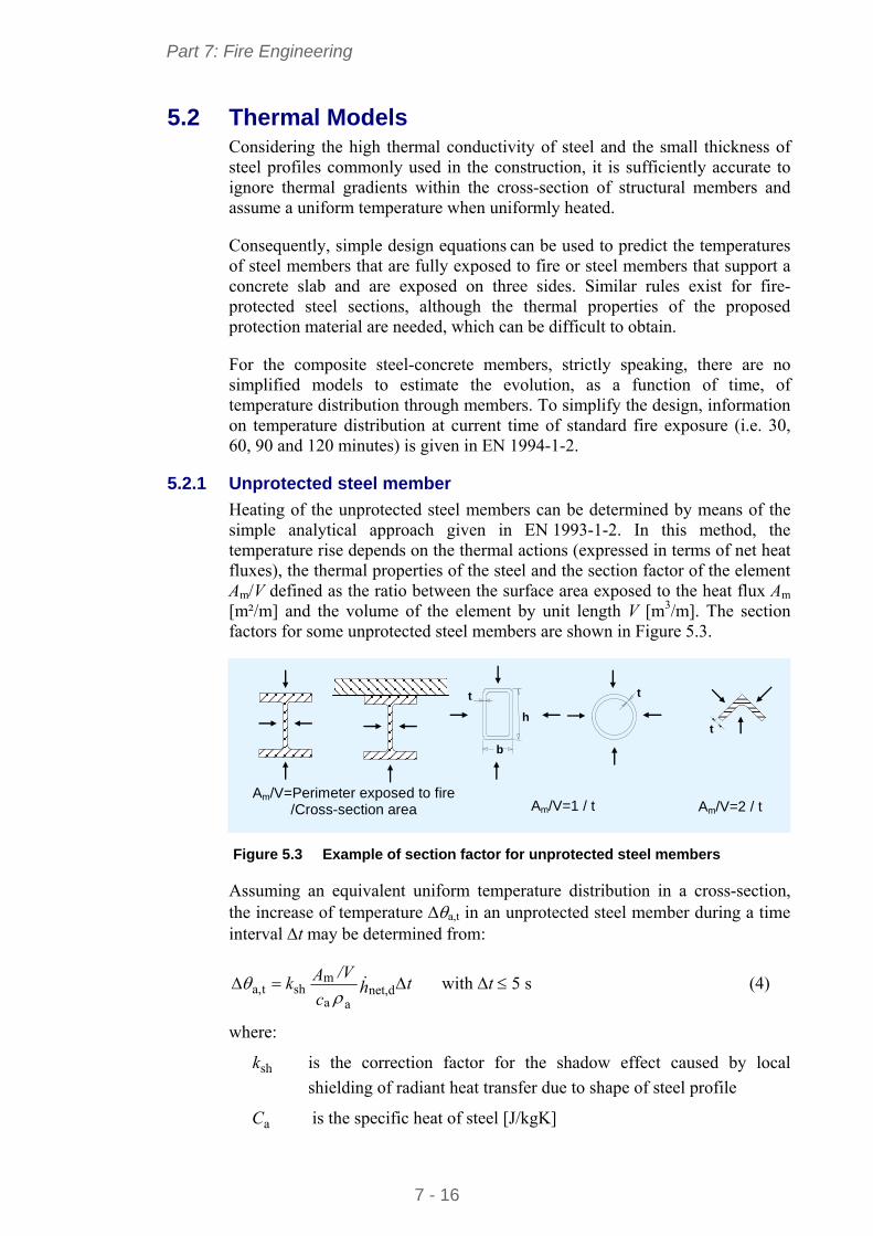
Heating of the unprotected steel members can be determined by means of the simple analytical approach given in EN 1993-1-2. In this method, the temperature rise depends on the thermal actions (expressed in terms of net heat fluxes), the thermal properties of the steel and the section factor of the element Am/V defined as the ratio between the surface area exposed to the heat flux Am [m²/m] and the volume of the element by unit length V [m3/m]. The section factors for some unprotected steel members are shown in Figure 5.3.
b
h
t t
t
Am/V=Perimeter exposed to fire /Cross-section area Am/V=1 / t Am/V=2 / t
Figure 5.3 Example of section factor for unprotected steel members
Assuming an equivalent uniform temperature distribution in a cross-section, the increase of temperature a,t in an unprotected steel member during a time interval t may be determined from:
thc
/VAk dnet,aa
mshta,
with t 5 s (4)
where:
shk is the correction factor for the shadow effect caused by local
shielding of radiant heat transfer due to shape of steel profile
aC is the specific heat of steel [J/kgK]
Part 7: Fire Engineering
7 - 17
a is the unit mass of steel [kg/m3]
h dnet, is the net heat flux per unit area [W/m²]
Solving the incremental equation step by step gives the temperature development of the steel element during the fire. In order to assure the numerical convergence of the solution, some upper limit must be taken for the time increment t. In EN 1993-1-2, it is suggested that the value of t should not be taken as more than 5 seconds.
The thermal actions are determined by the net heat flux rnet,h absorbed by the
steel member during the fire exposure. It is expressed in terms of the hot gas
temperature as the sum of two distinct fluxes: a convective component cnet,h
and a radiant component rhnet, .
Convective heat flux is expressed as:
)( mgccnet, h (5)
where:
c is the coefficient of heat transfer by convection [W/m²K]
g is the gas temperature [°C]
m is the surface temperature of the member [°C]
Radiant heat flux is given by:
)273)()273(( 4m
4rm0rnet, h (6)
where:
is the configuration factor, including position and shape effect (<1)
m is the surface emissivity of the member
r is the radiation temperature of the fire environment [°C] (r ≈ g)
m is the surface temperature of the member [°C]
0 is the Stephan Boltzmann constant [= 5,67 10-8 W/m2 K4]
According to EN 1991-1-2, for many practical cases the configuration factor may be taken equal to unity. The coefficient of convection ( c ) varies from
25 W/m²K (standard fire conditions) to 50 W/m²K (hydrocarbon fire conditions). The emissivity of carbon steel and composite steel and concrete members may be taken as 7,0m .
Part 7: Fire Engineering
7 - 18
For cross-section with a convex shape, such as hollow steel sections, fully embedded in fire, the shadow effect does not play a role and it can be taken that ksh = 1. Otherwise, the correction factor for the shadow effects ksh is given by:
casesothersfor
actions fire nominalunder sections-Ifor
/
]/[/
]/[9,0
m
bm
m
bm
sh
VA
VAVA
VA
k (7)
where:
bm ]/[ VA is the box value of the section factor [m-1].
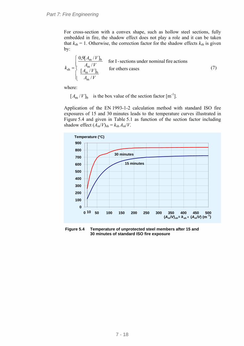
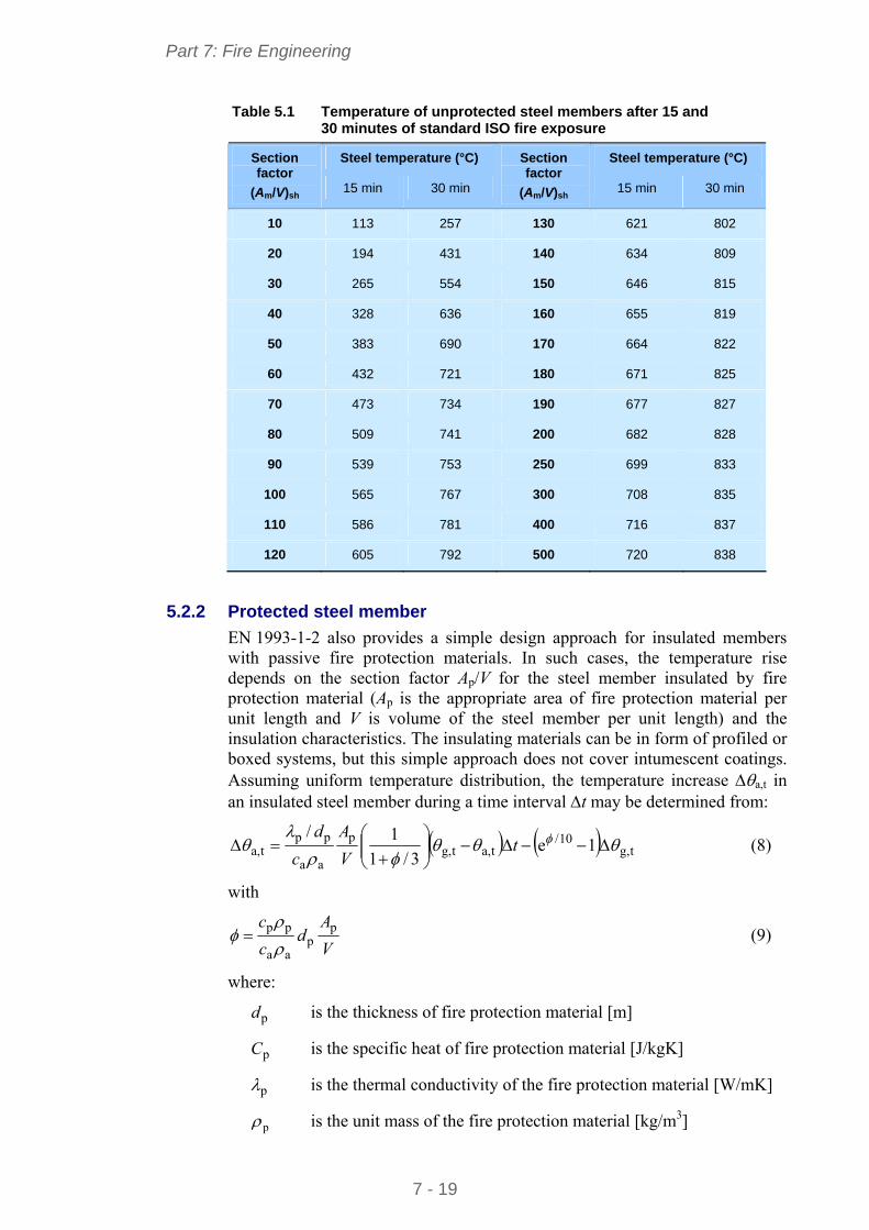
Application of the EN 1993-1-2 calculation method with standard ISO fire exposures of 15 and 30 minutes leads to the temperature curves illustrated in Figure 5.4 and given in Table 5.1 as function of the section factor including shadow effect (Am/V)sh = ksh Am/V.
Figure 5.4 Temperature of unprotected steel members after 15 and
30 minutes of standard ISO fire exposure
0
100
200
300
400
500
600
700
800
900
0 50 100 150 200 250 300 350 400 450 500(Am/V) sh= k sh (Am /V) (m -1)
Temperature (°C)
15 minutes
30 minutes
10
Part 7: Fire Engineering
7 - 19
Table 5.1 Temperature of unprotected steel members after 15 and 30 minutes of standard ISO fire exposure
Steel temperature (°C) Steel temperature (°C) Section factor
(Am/V)sh 15 min 30 min
Section factor
(Am/V)sh 15 min 30 min
10 113 257 130 621 802
20 194 431 140 634 809
30 265 554 150 646 815
40 328 636 160 655 819
50 383 690 170 664 822
60 432 721 180 671 825
70 473 734 190 677 827
80 509 741 200 682 828
90 539 753 250 699 833
100 565 767 300 708 835
110 586 781 400 716 837
120 605 792 500 720 838
5.2.2 Protected steel member
EN 1993-1-2 also provides a simple design approach for insulated members with passive fire protection materials. In such cases, the temperature rise depends on the section factor Ap/V for the steel member insulated by fire protection material (Ap is the appropriate area of fire protection material per unit length and V is volume of the steel member per unit length) and the insulation characteristics. The insulating materials can be in form of profiled or boxed systems, but this simple approach does not cover intumescent coatings. Assuming uniform temperature distribution, the temperature increase a,t in an insulated steel member during a time interval t may be determined from:
tg,10/
ta,tg,p
aa
ppta, 1e
3/1
1/
tV
A
c
d (8)
with
V
Ad
c
c pp
aa
pp
(9)
where:
pd is the thickness of fire protection material [m]
pC is the specific heat of fire protection material [J/kgK]
p is the thermal conductivity of the fire protection material [W/mK]
p is the unit mass of the fire protection material [kg/m3]
Part 7: Fire Engineering
7 - 20
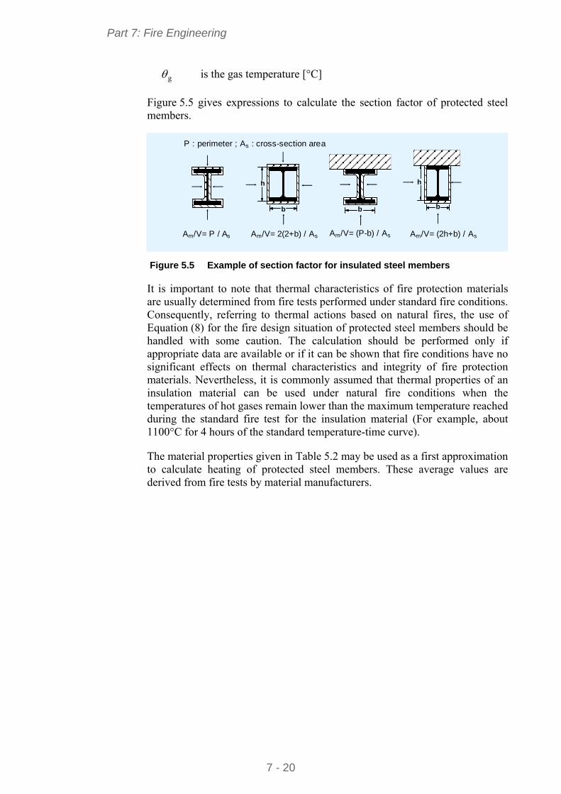
g is the gas temperature [°C]
Figure 5.5 gives expressions to calculate the section factor of protected steel members.
Am/V= (P-b) / As
b
Am/V= (2h+b) / As Am/V= 2(2+b) / As Am/V= P / As
h
b b
h
P : perimeter ; As : cross-section area
Figure 5.5 Example of section factor for insulated steel members
It is important to note that thermal characteristics of fire protection materials are usually determined from fire tests performed under standard fire conditions. Consequently, referring to thermal actions based on natural fires, the use of Equation (8) for the fire design situation of protected steel members should be handled with some caution. The calculation should be performed only if appropriate data are available or if it can be shown that fire conditions have no significant effects on thermal characteristics and integrity of fire protection materials. Nevertheless, it is commonly assumed that thermal properties of an insulation material can be used under natural fire conditions when the temperatures of hot gases remain lower than the maximum temperature reached during the standard fire test for the insulation material (For example, about 1100°C for 4 hours of the standard temperature-time curve).
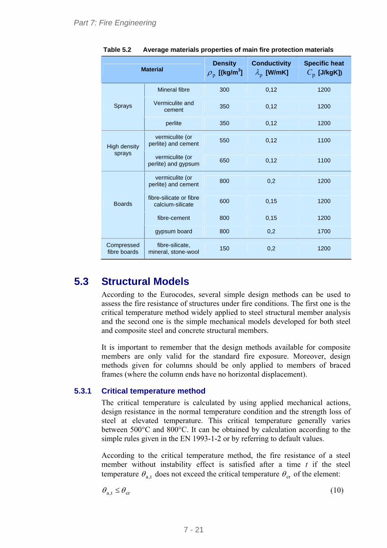
The material properties given in Table 5.2 may be used as a first approximation to calculate heating of protected steel members. These average values are derived from fire tests by material manufacturers.
Part 7: Fire Engineering
7 - 21
Table 5.2 Average materials properties of main fire protection materials
Material Density
p [(kg/m3]
Conductivity
p [W/mK]
Specific heat
pC [J/kgK])
Mineral fibre 300 0,12 1200
Vermiculite and cement
350 0,12 1200 Sprays
perlite 350 0,12 1200
vermiculite (or perlite) and cement
550 0,12 1100 High density
sprays vermiculite (or
perlite) and gypsum 650 0,12 1100
vermiculite (or perlite) and cement
800 0,2 1200
fibre-silicate or fibre calcium-silicate
600 0,15 1200
fibre-cement 800 0,15 1200
Boards
gypsum board 800 0,2 1700
Compressed fibre boards
fibre-silicate, mineral, stone-wool
150 0,2 1200
5.3 Structural Models According to the Eurocodes, several simple design methods can be used to assess the fire resistance of structures under fire conditions. The first one is the critical temperature method widely applied to steel structural member analysis and the second one is the simple mechanical models developed for both steel and composite steel and concrete structural members.
It is important to remember that the design methods available for composite members are only valid for the standard fire exposure. Moreover, design methods given for columns should be only applied to members of braced frames (where the column ends have no horizontal displacement).
5.3.1 Critical temperature method
The critical temperature is calculated by using applied mechanical actions, design resistance in the normal temperature condition and the strength loss of steel at elevated temperature. This critical temperature generally varies between 500°C and 800°C. It can be obtained by calculation according to the simple rules given in the EN 1993-1-2 or by referring to default values.
According to the critical temperature method, the fire resistance of a steel member without instability effect is satisfied after a time t if the steel temperature t,a does not exceed the critical temperature cr of the element:
crt,a (10)
Part 7: Fire Engineering
7 - 22
The critical temperature of the member can be calculated from the degree of utilization 0 as follows:
48219674.0
1ln19,39 833.3
0
cr (11)
The degree of utilization 0 is obtained from:
d,0fi,
dfi,0 R
E (12)
where:
dfi,E is the design effect of actions for the fire design situation, according
to EN 1991-1-2
d,0fi,R is the corresponding design resistance of the steel member, for the
fire design situation, at time t = 0 (at normal temperature) but with safety factor fi,M in fire situation
The expression for θcr can be used for all classes of section except the very slender Class 4 sections, for which a single conservative critical temperature of 350°C should be used.
In principle, Expression (11) applies for members in pure bending, short columns without buckling and members in tension, heated uniformly or with slight temperature gradient. However, in situations of instability (slender columns, unrestrained beams), the method becomes applicable by calculating the design resistance for the fire design situation at time t = 0 with a value of the slenderness that takes into account temperature effects on the slenderness of structural members. As a simplification, the slenderness in fire situations can be taken as 3.1 (where is the non dimensional slenderness at
normal temperature).
As an alternative, to relation (11) nationally determined critical temperatures can be given in the National Annex to EN 1993-1-2.
A simple conservative expression for 0 can also be used for tension members and restrained beams (where lateral-torsional buckling is not a potential failure mode):
21M
fi,Mt,fi0
(13)
where:
t,fi is the load level at time t
fi,M is the relevant partial safety factor for fire situation ( 1fi,M )
0M is the partial safety factor at normal temperature ( 10M )
Part 7: Fire Engineering
7 - 23
κ1, κ2 are the adaptation factors to take account a non-uniform temperature distribution on steel member.
The load level at time t is defined as:
d
dfi,tfi, R
E (14)
where:
dfi,E is the design effect of actions for the fire design situation, according
to EN 1991-1-2
dR is the ultimate resistance in room temperature
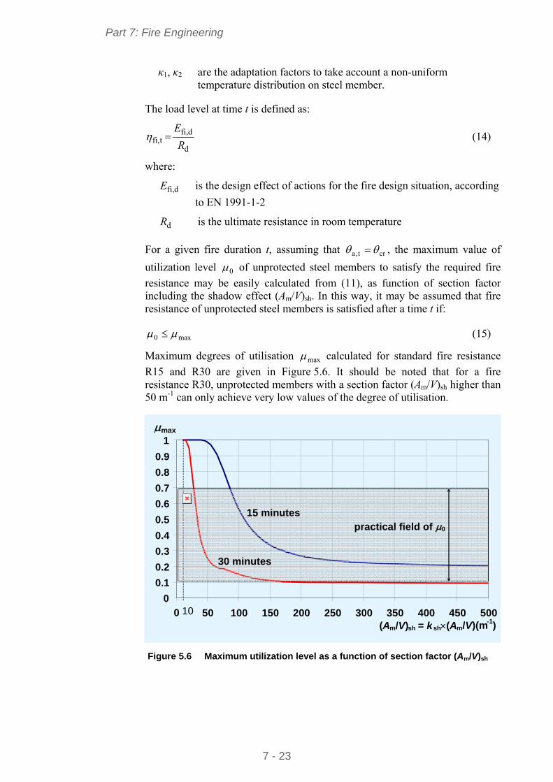
For a given fire duration t, assuming that crt,a , the maximum value of
utilization level 0 of unprotected steel members to satisfy the required fire
resistance may be easily calculated from (11), as function of section factor including the shadow effect (Am/V)sh. In this way, it may be assumed that fire resistance of unprotected steel members is satisfied after a time t if:
max0 (15)
Maximum degrees of utilisation max calculated for standard fire resistance
R15 and R30 are given in Figure 5.6. It should be noted that for a fire resistance R30, unprotected members with a section factor (Am/V)sh higher than 50 m-1 can only achieve very low values of the degree of utilisation.
Figure 5.6 Maximum utilization level as a function of section factor (Am/V)sh
0
0.1
0.2
0.3
0.4
0.5
0.6
0.7
0.8
0.9
1
0 50 100 150 200 250 300 350 400 450 500(Am/V) sh = ksh (A m/V)(m-1)
max
10
15 minutes
30 minutes
practical field of 0
Part 7: Fire Engineering
7 - 24
5.3.2 Simple design method for steel members
According to EN 1993-1-2, the load-bearing function of a steel member should be assumed to be maintained at a time t if:
tfi,d,dfi, RE (16)
where:
dfi,E is the design effect of actions for the fire design situation, according
to EN 1991-1-2
tfi,d,R is the corresponding design resistance of the steel member, for the
fire design situation, at time t
The following simplified calculation methods allow the designer to assess the design fire resistance (buckling resistance, resistance moment) of steel members. They are mainly based on the assumption of constant temperature within the section.
Steel columns under compression only
The design resistance for the fire design situation at time t of a compression member with a Class 1, 2 or 3 cross-sections at a uniform temperature θa should be determined from:
Rdθy,fM,
M0fRdt,fi, NkN
ii
(17)
where:
θy,k is the reduction factor for the yield strength of steel at the steel
temperature θ reached at time t
fi,M is the partial safety factor for fire situation ( 1fi,M )
0M is the partial safety factor at normal temperature ( 10M )
RdN is the design resistance of the cross-section Npl,Rd for the normal
temperature design according to EN 1993-1-1
fi is the reduction factor for flexural buckling in the fire design situation
The reduction factor fi for flexural buckling is obtained from the non-
dimensional slenderness at temperature θ using:
2θ
2θθ
f1
i but fi 1.0 (18)
with
2θθθ 1
2
1
Part 7: Fire Engineering
7 - 25
where:
is the imperfection factor for the appropriate buckling curve given
by y/23565.0 f with fy is characteristic yield strength of steel.
The non dimensional slenderness at temperature θ is given by:
θE,θy,θ / kk (19)
where:
θy,k is the reduction factor for the yield strength of steel at the
temperature
θE,k is the reduction factor for the slope of the linear elastic range at the
temperature
The non dimensional slenderness at normal temperature, according to EN 1993-1-1
The non dimensional slenderness at normal temperature is given by:
E
f
iycr
π
1 (20)
where:
cr is the buckling length in the buckling plane considered
i is the radius of gyration about the relevant axis, determined using the properties of the gross cross-section
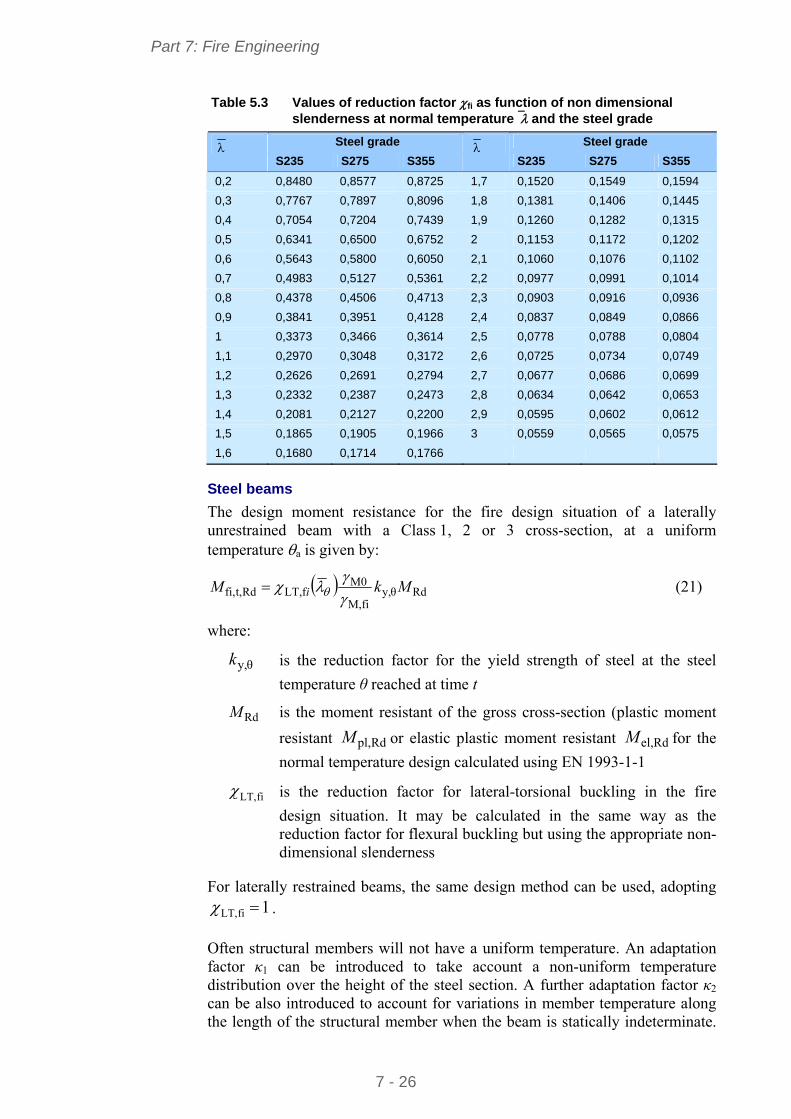
For a practical use, the reduction factor if for flexural buckling can be directly
calculated from values given in Table 5.3, according to the steel grade and the non dimensional slenderness of steel member at normal temperature . Values of reduction factor fi in Table 5.3 were calculated assuming a slenderness in
the fire situation equal to 3.1θ . For intermediate value of non-
dimensional relative slenderness, linear interpolation may be used.
Part 7: Fire Engineering
7 - 26
Table 5.3 Values of reduction factor fi as function of non dimensional slenderness at normal temperature and the steel grade
Steel grade Steel grade S235 S275 S355
S235 S275 S355
0,2 0,8480 0,8577 0,8725 1,7 0,1520 0,1549 0,1594
0,3 0,7767 0,7897 0,8096 1,8 0,1381 0,1406 0,1445
0,4 0,7054 0,7204 0,7439 1,9 0,1260 0,1282 0,1315
0,5 0,6341 0,6500 0,6752 2 0,1153 0,1172 0,1202
0,6 0,5643 0,5800 0,6050 2,1 0,1060 0,1076 0,1102
0,7 0,4983 0,5127 0,5361 2,2 0,0977 0,0991 0,1014
0,8 0,4378 0,4506 0,4713 2,3 0,0903 0,0916 0,0936
0,9 0,3841 0,3951 0,4128 2,4 0,0837 0,0849 0,0866
1 0,3373 0,3466 0,3614 2,5 0,0778 0,0788 0,0804
1,1 0,2970 0,3048 0,3172 2,6 0,0725 0,0734 0,0749
1,2 0,2626 0,2691 0,2794 2,7 0,0677 0,0686 0,0699
1,3 0,2332 0,2387 0,2473 2,8 0,0634 0,0642 0,0653
1,4 0,2081 0,2127 0,2200 2,9 0,0595 0,0602 0,0612
1,5 0,1865 0,1905 0,1966 3 0,0559 0,0565 0,0575
1,6 0,1680 0,1714 0,1766
Steel beams
The design moment resistance for the fire design situation of a laterally unrestrained beam with a Class 1, 2 or 3 cross-section, at a uniform temperature a is given by:
Rdθy,fiM,
M0fLT,Rdt,fi, MkM i
(21)
where:
θy,k is the reduction factor for the yield strength of steel at the steel
temperature θ reached at time t
RdM is the moment resistant of the gross cross-section (plastic moment
resistant Rdpl,M or elastic plastic moment resistant Rdel,M for the
normal temperature design calculated using EN 1993-1-1
fiLT, is the reduction factor for lateral-torsional buckling in the fire
design situation. It may be calculated in the same way as the reduction factor for flexural buckling but using the appropriate non-dimensional slenderness
For laterally restrained beams, the same design method can be used, adopting 1fiLT, .
Often structural members will not have a uniform temperature. An adaptation factor κ1 can be introduced to take account a non-uniform temperature distribution over the height of the steel section. A further adaptation factor κ2 can be also introduced to account for variations in member temperature along the length of the structural member when the beam is statically indeterminate.
Part 7: Fire Engineering
7 - 27
The value of the adaptation factors κ1 and κ2 should be taken according to EN 1993-1-2.
Members subject to combined bending and axial compression
A simplified design method is also available to verify the fire resistance of steel members subjected to combined bending and axial compression, such as slender columns under eccentric load and long beams with lateral buckling. For this situation, the simple calculation model takes into account the combination effect of bending and compression by combining above two models for the simple loading condition. Detailed information is given in EN 1993-1-2.
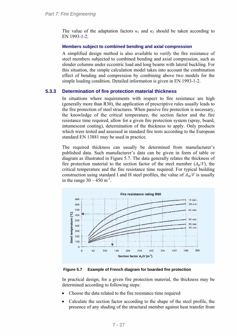
5.3.3 Determination of fire protection material thickness
In situations where requirements with respect to fire resistance are high (generally more than R30), the application of prescriptive rules usually leads to the fire protection of steel structures. When passive fire protection is necessary, the knowledge of the critical temperature, the section factor and the fire resistance time required, allow for a given fire protection system (spray, board, intumescent coating), determination of the thickness to apply. Only products which were tested and assessed in standard fire tests according to the European standard EN 13881 may be used in practice.
The required thickness can usually be determined from manufacturer’s published data. Such manufacturer’s data can be given in form of table or diagram as illustrated in Figure 5.7. The data generally relates the thickness of fire protection material to the section factor of the steel member (Ap/V), the critical temperature and the fire resistance time required. For typical building construction using standard I and H steel profiles, the value of Am/V is usually in the range 30 – 450 m-1.
Fire resistance rating R60
Section factor Ap/V (m-1)
Ste
el
tem
pe
ratu
re (
°C)
Figure 5.7 Example of French diagram for boarded fire protection
In practical design, for a given fire protection material, the thickness may be determined according to following steps:
Choose the data related to the fire resistance time required
Calculate the section factor according to the shape of the steel profile, the presence of any shading of the structural member against heat transfer from
Part 7: Fire Engineering
7 - 28
the fire during the fire duration (for example a concrete slab put on the upper flange of the profile), the type of fire protection (according to the outline of the steel profile or in box)
Determine the thickness from the manufacturer’s data using the critical temperature and the section factor. Linear interpolation is permissible to determine thickness.
The European Convention for Constructional Steelwork (ECCS) has developed so-called Euro-nomograms[13], which relate for a given time of standard fire exposure, the temperature reached by insulated steel members to the factor (λp/dp) (Ap/V) depending on the fire protection characteristics (λp and dp) and the section factor Ap/V. Note that these Euro-nomograms are determined on the basis of the ENV version of the fire part of Eurocode 3. Also for this reason they should be used with some caution. Other nomograms based on EN 1993-1-2 have been recently developed[14].
5.3.4 Design tables for composite members
Design tables for composite members are given in EN 1994-1-2. They are applicable only to steel and concrete composite members (composite beams with partially or fully concrete encasement of steel beam, composite columns with partially or fully concrete encased profiles, composite columns with concrete filled rectangular or circular steel hollow sections). They use predefined values, based mainly on standard fire test results, improved with analytical investigation. The tables allow the designer to quickly obtain the member size (minimum dimensions of cross-section, the necessary reinforcing steel area and its minimum concrete cover) as a function of the load level for common standard fire resistances. The most important advantage of this method is the ease of application. However it is limited by a very strict set of geometrical rules and it gives more conservative results compared to other simple calculation models or advanced calculation models. As a consequence, it should only be applied for the pre-design of a building.
Detailed information is given in EN 1994-1-2.
5.3.5 Simplified calculations models for composite members
The following design methods have been developed to predict the resistance of individual members when exposed to a standard fire curve. Therefore they are not applicable to “natural” fires.
Only the design methods for the most commonly used composite members in single-storey building (composite columns and partially encased concrete beams) are described here.
Composite columns
The simple design methods for columns allow the designer to assess the fire resistance of a composite column by calculating its buckling resistance using the temperature distribution through the cross-section and the corresponding reduced material strength defined at the required fire resistance time. This method is based on the buckling curve concept: the plastic resistance to axial compression Nfi,pl,Rd and the effective flexural stiffness (EI)fi,eff, are used to derive a reduction factor for buckling. The method is applicable to all types of
Part 7: Fire Engineering
7 - 29
composite column provide that an appropriate buckling curve is used. Checking the column consists of proving that the axial compression (for the combination of actions considered in fire situation according to EN 1991-1-2) is less than the buckling resistance of the column.
For a given temperature distribution across the cross-section, the design resistance of a composite column Nfi,Rd can be determined from the appropriate buckling column curve relating the load capacity Nfi,Rd to the plastic load Nfi,pl,Rd and the elastic critical load Nfi,cr as follows:
Rdpl,fi,θRdfi, .NN (22)
is the reduction factor for flexural buckling depending on the slenderness in
fire situation θ .For composite columns, θ may be defined as:
crfi,Rpl,fi,θ / NN (23)
where:
crfi,N is the Euler buckling load
Rpl,fi,N is the value of Nfi,pl,Rd according to (24) when the partial security
factors M,fi,a, M,fi,s, and M,fi,c,of the materials are taken as 1.0
The reduction factor is determined as for normal temperature design but using an appropriate buckling curve defined as function of column type (partially encased steel section, filled hollow steel section).
The ultimate plastic load, Nfi,pl,Rd of the cross-section is determined by summing the strengths of every part of the cross-section (yield stress for steel parts, compressive strength for concrete parts) multiplied by the corresponding areas, taking into account the effect of temperature on these elements, without considering their interaction (due to differential thermal stresses), i.e.:
m
ck
sj
fA
fA
fAN )()().(
cfi,M,
θc,
sfi,M,
θs,
afi,M,
θay,aRdpl,fi,
(24)
Nfi,cr is the Euler buckling load calculated as a function of the effective flexural
stiffness of the cross-section efffi,)(EI and the buckling length of the
column in fire situation, i.e.:
2θ
efffi,2crfi,
)(π
EIN (25)
The effective rigidity (EI)fi,eff is determined from:
mkj
IEIEIEEI )()()()( θc,θsec,c,θc,θs,θs,θs,θa,θa,θa,efffi, (26)
where:
θ,iE is the characteristic modulus of material i at the temperature . For
steel, it is the modulus of elasticity. For concrete: 2/3 secc,c, EE
Part 7: Fire Engineering
7 - 30
where θsec,c,E is the characteristic value for the secant modulus of
concrete in the fire situation, given by the ration between fc,θ and cu,
Ii is the second moment of area of material i related to the central axis (y or z) of the composite cross-section
a, (for steel profile), s, (for reinforcements) and c, (for concrete) are reduction coefficients due to the differential effects of thermal stresses.
Detailed information is given in EN 1994-1-2 §4.3.5.
Partially encased steel beams
The simple design method for partially encased steel beams allows the designer to assess the fire resistance by calculating its bending resistance at the required fire resistance time. It is based on the simple plastic moment theory. The method requires the calculation of the neutral axis and corresponding bending resistance, taking into account temperature distribution through the cross-section and corresponding reduced material strength. Distinction is made between sagging moment capacity (usually at mid-span) and the hogging moment capacity (at the support, if appropriate). If the applied moment is less than the bending resistance of the beam, the member is deemed to have adequate fire resistance.
The plastic neutral axis of the beam is determined such that the tensile and compressive forces acting in the section are in equilibrium:
01 cfi,M,
c,,θc,
1 afi,M,
,y,y,
m
j
jjj
n
i
iii
fkA
fkA
(27)
where:
fy,i is the nominal yield strength for the elemental steel area Ai taken as positive on the compression side of the plastic neutral axis and negative on the tension side
fc,j is the nominal compressive strength for the elemental concrete area Aj taken as positive on the compression side of the plastic neutral axis and negative on the tension side
The design moment resistance Rdt,fi,M may be determined from:
m
1j c,fi,M
jc,j,c,jj
n
1i a,fi,M
i,yi,y,iiRd,t,fi
fkzA
fkzAM
(28)
where:
zi, zj are the distances from the plastic neutral axis to the centroid of the elemental area Ai and Aj
Part 7: Fire Engineering
7 - 31
For the calculation of the design value of the moment resistance, the cross-section of the beam is divided into various components, namely:
the flanges of the steel profile
the web (lower and upper parts) of the steel profile
the reinforcing bars
the encased concrete.
To each of these parts of the cross-section, simple rules are given which define the effect of temperatures and allow calculation of the reduced characteristic strength in function of the standard fire resistance R30, R60, R90 or R120.
Detailed information is given in EN 1994-1-2 §4.3.4.
5.4 Specific design rules for single-storey buildings National fire regulations of many European countries have been changed recently to introduce, for single-storey storage and industrial buildings with significant fire risks (high fire loads), specific safety requirements in terms of structural behaviour as an alternative to standard prescriptive requirements. The following criteria relating to the structural behaviour of storage and industrial buildings (load-bearing structure, façade elements, roofing and fire walls) must be satisfied to ensure adequate life safety for building occupants and firemen:
In case of fire occurring in one of the cells of the building, its structure (including façade elements) must not collapse towards the outside.
In case of fire occurring in one of the cells of the building, the localized failure of the cell in fire must not lead to the collapse of the neighbouring cells.
To help the design of storage and industrial buildings with a steel structure, several simple design methods can be used5,6. These design methods allow the designer to easily prove that the behaviour of the steel structure of these buildings in fire situations fulfils the above criteria. The methods are implemented in the LUCA software[15].
The design methods enable the designer to:
Evaluate forces induced by the collapse of the heated part of the structure. These forces should be used as additional horizontal load for the stability check of the part of the frame that remains cold during the fire. That part can be assessed using normal conditions design tools for structure analysis.
Provide maximum horizontal displacements developed at the ends of the compartment affected by the fire. These displacements are used to ensure that movements of the structure in the event of fire do not adversely affect the stability of fire walls or building façades. Design methods used for this verification depend on the type of the wall (such as in lightweight concrete, reinforced concrete, hollow block, steel sheeting with insulator, plasterboard, bricks, etc.) and connection to the steel frame.
Part 7: Fire Engineering
7 - 32
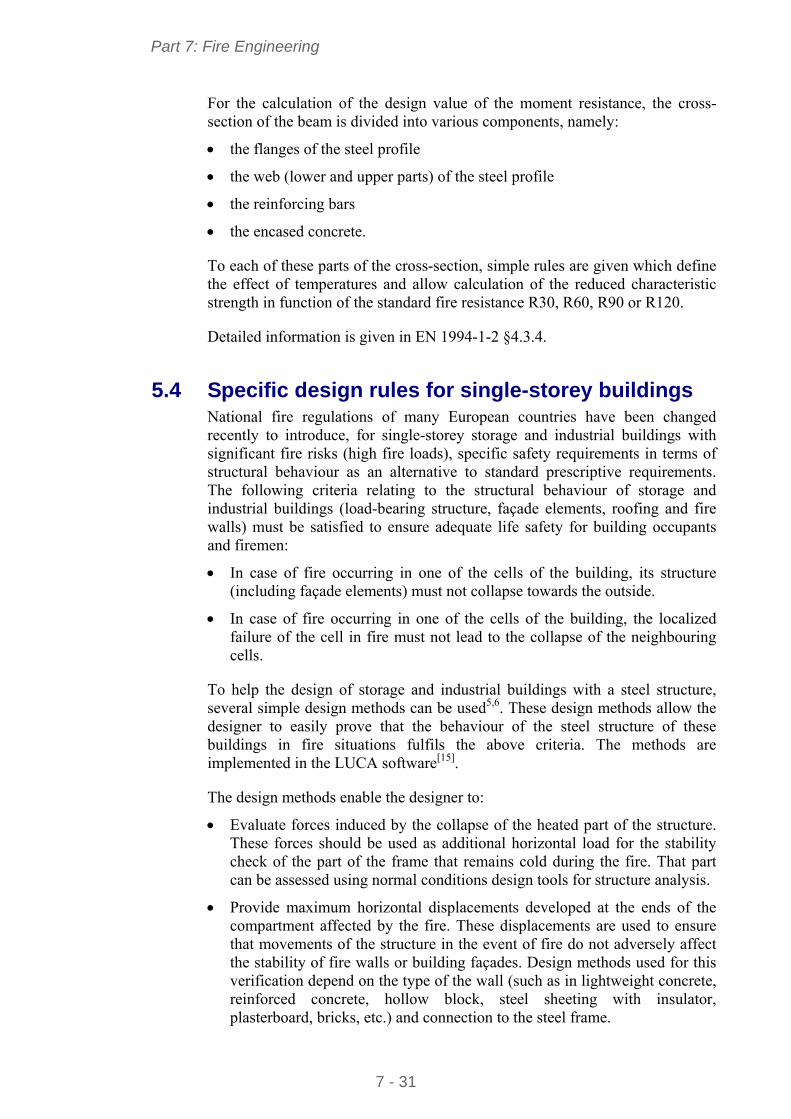
The following buildings can de designed by these methods:
Storage and industrial buildings with steel structure. Either steel portal frames with standard H or I hot rolled profiles or equivalent welded plate girders, or steel frames based on lattice beams with columns in standard H or I hot rolled profiles or equivalent welded plate girders
Storage and industrial buildings of portal frame construction divided in several cells, separated one from each other by fire walls. These walls can be either perpendicular to the steel portal frames or parallel to the steel portal frames (see Figure 5.8).
These methods were specifically developed for storage and industrial buildings but they can also be applied to other type of single-storey buildings.
fire wall perpendicular to the steel frame
fire wall parallel to the steel frame
Figure 5.8 Location of fire wall compared to steel frames
Calculation methods (see Section 5.5) are only required when fire walls are perpendicular to steel frames of the building and the building height exceeds 20 m5. When fire walls are parallel to steel frames, the risks of collapse towards the outside and progressive collapse (between different fire compartments) can be simply avoided by following the recommendations in Section 5.5.3.
Part 7: Fire Engineering
7 - 33
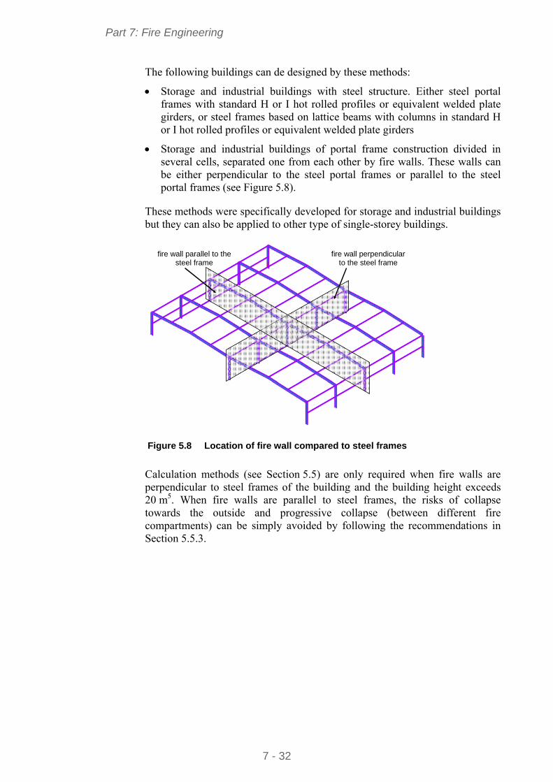
5.5 Simplified design methods A flowchart showing simplified calculation methods is given in Figure 5.9.
yes
No
No
yes
(*) For all the possible fire scenarios according to the building arrangement
Industrial hall
Checking of failure modes
Choice of fire scenario(*)
(see Figure 5-14)
Calculation of displacements of the steel structure δi (see expression (30))
Calculation of tensile force Fi (see expression (29))
Checking of the compatibility of displacements Steel structure and partition elements Steel structure and facade elements
Checking of the stability at the ultimate limit states of the cold
parts of the steel structure
End of checking
yes
Change in the steel structure
Change in the design of partition or facade elements to ensure the compatibility of displacements
No
Is it a simple isolated portal frame?
Design recommendations at the bottom of columns
(see end of §5.6.2)
yes
Figure 5.9 Application flowchart of calculation methods
The calculations of tensile force and lateral displacements at compartment ends must be performed for all possible fire scenarios. Examples of scenarios are given in Section 5.5.3. Calculation methods are given in Sections 5.5.1 and 5.5.2.
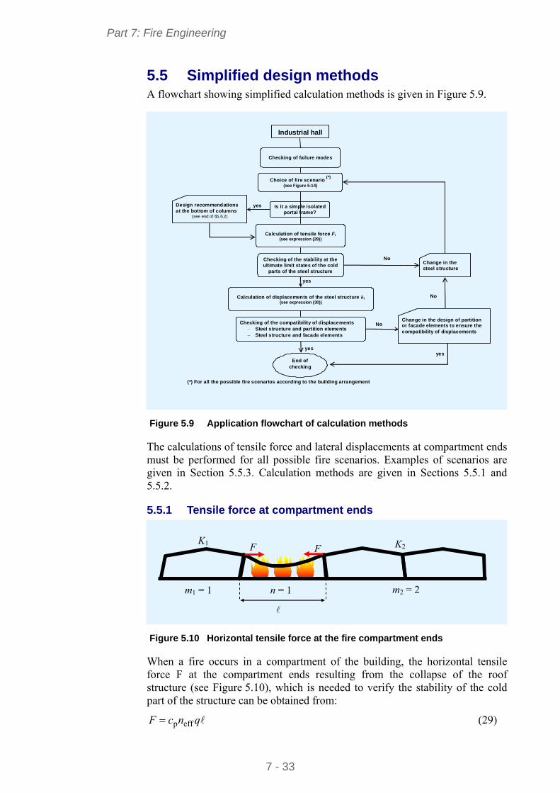
5.5.1 Tensile force at compartment ends
m1 = 1 m2 = 2 n = 1
K2 F F
K1
Figure 5.10 Horizontal tensile force at the fire compartment ends
When a fire occurs in a compartment of the building, the horizontal tensile force F at the compartment ends resulting from the collapse of the roof structure (see Figure 5.10), which is needed to verify the stability of the cold part of the structure can be obtained from:
qncF effp (29)
Part 7: Fire Engineering
7 - 34
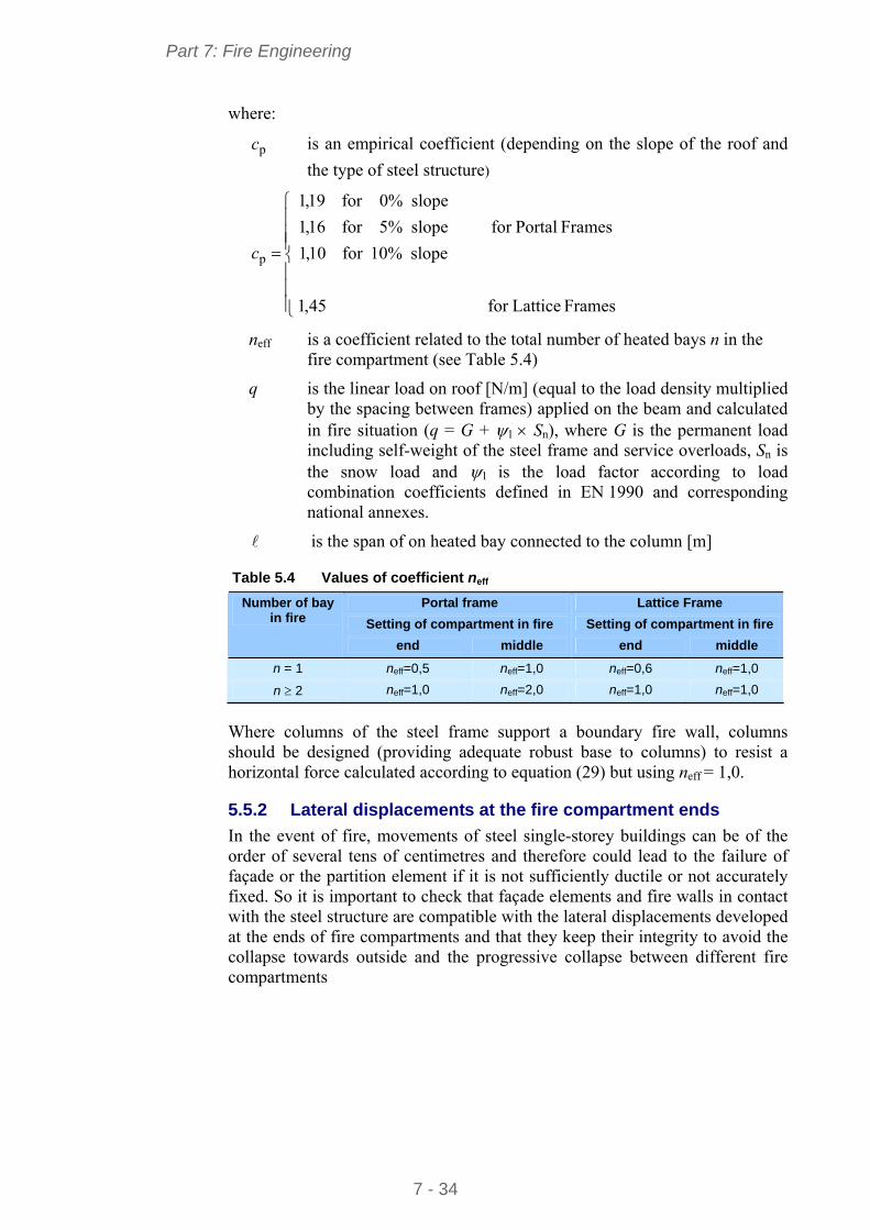
where:
pc is an empirical coefficient (depending on the slope of the roof and
the type of steel structure)
Frames Latticefor
Frames Portalfor
45,1
slope10%for10,1
slope5%for16,1
slope0%for19,1
pc
neff is a coefficient related to the total number of heated bays n in the fire compartment (see Table 5.4)
q is the linear load on roof [N/m] (equal to the load density multiplied by the spacing between frames) applied on the beam and calculated in fire situation (q = G + 1 Sn), where G is the permanent load including self-weight of the steel frame and service overloads, Sn is the snow load and 1 is the load factor according to load combination coefficients defined in EN 1990 and corresponding national annexes.
is the span of on heated bay connected to the column [m]
Table 5.4 Values of coefficient neff
Portal frame Lattice Frame
Setting of compartment in fire Setting of compartment in fire
Number of bay in fire
end middle end middle
n = 1 neff=0,5 neff=1,0 neff=0,6 neff=1,0
n 2 neff=1,0 neff=2,0 neff=1,0 neff=1,0
Where columns of the steel frame support a boundary fire wall, columns should be designed (providing adequate robust base to columns) to resist a horizontal force calculated according to equation (29) but using neff = 1,0.
5.5.2 Lateral displacements at the fire compartment ends
In the event of fire, movements of steel single-storey buildings can be of the order of several tens of centimetres and therefore could lead to the failure of façade or the partition element if it is not sufficiently ductile or not accurately fixed. So it is important to check that façade elements and fire walls in contact with the steel structure are compatible with the lateral displacements developed at the ends of fire compartments and that they keep their integrity to avoid the collapse towards outside and the progressive collapse between different fire compartments
Part 7: Fire Engineering
7 - 35
Maximum lateral displacements δi (i = 1, 2) induced at the top of columns located at the compartment ends can be obtained using the following expression (see Figure 5.11):
building theof middle in the is fire when the;Max
building theof end at the is fire when the
tht
tht
ii
ii
K
Fnlc
K
K
nlcK
K
(30)
where:
n is the number of heated bays
Ki is the equivalent lateral stiffness of the considered part i of the structure [N/m]
Kt is the equivalent stiffness (depending on equivalent stiffnesses
1K and 2K ) given by:
21
21t KK
KKK
is the span of one heated bay connected to the column [m]
F is the tensile force [N]
cth is an empirical coefficient (dependent on the slope of the roof and the type of steel structure)
Frames Lattice for
Frames Portal for
009,0
slope10%for015,0
slope5%for011,0
slope0%for01,0
thc
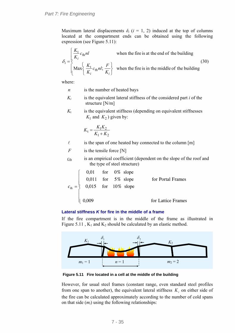
Lateral stiffness K for fire in the middle of a frame
If the fire compartment is in the middle of the frame as illustrated in Figure 5.11 , K1 and K2 should be calculated by an elastic method.
1 2
m1 = 1 m2 = 2 n = 1
K2
K1
Figure 5.11 Fire located in a cell at the middle of the building
However, for usual steel frames (constant range, even standard steel profiles from one span to another), the equivalent lateral stiffness iK on either side of
the fire can be calculated approximately according to the number of cold spans on that side (mi) using the following relationships:
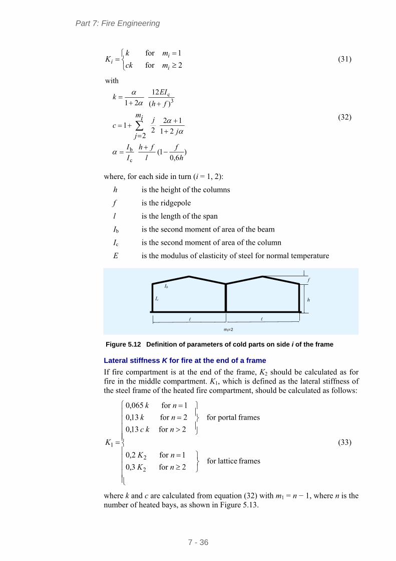
Part 7: Fire Engineering
7 - 36
2for
1for
i
ii mck
mkK (31)
)6,0
1(
21
12
22
1
)(
12
21
with
c
b
3c
h
f
l
fh
I
I
j
im
j
jc
fh
EIk
(32)
where, for each side in turn (i = 1, 2):
h is the height of the columns
f is the ridgepole
l is the length of the span
Ib is the second moment of area of the beam
Ic is the second moment of area of the column
E is the modulus of elasticity of steel for normal temperature
f
h
mi=2
Ib
Ic
Figure 5.12 Definition of parameters of cold parts on side i of the frame
Lateral stiffness K for fire at the end of a frame
If fire compartment is at the end of the frame, K2 should be calculated as for fire in the middle compartment. K1, which is defined as the lateral stiffness of the steel frame of the heated fire compartment, should be calculated as follows:
frames latticefor 2for3,0
1for2,0
framesportalfor
2for13,0
2for13,0
1for065,0
2
2
1
nK
nK
nkc
nk
nk
K (33)
where k and c are calculated from equation (32) with m1 = n − 1, where n is the number of heated bays, as shown in Figure 5.13.
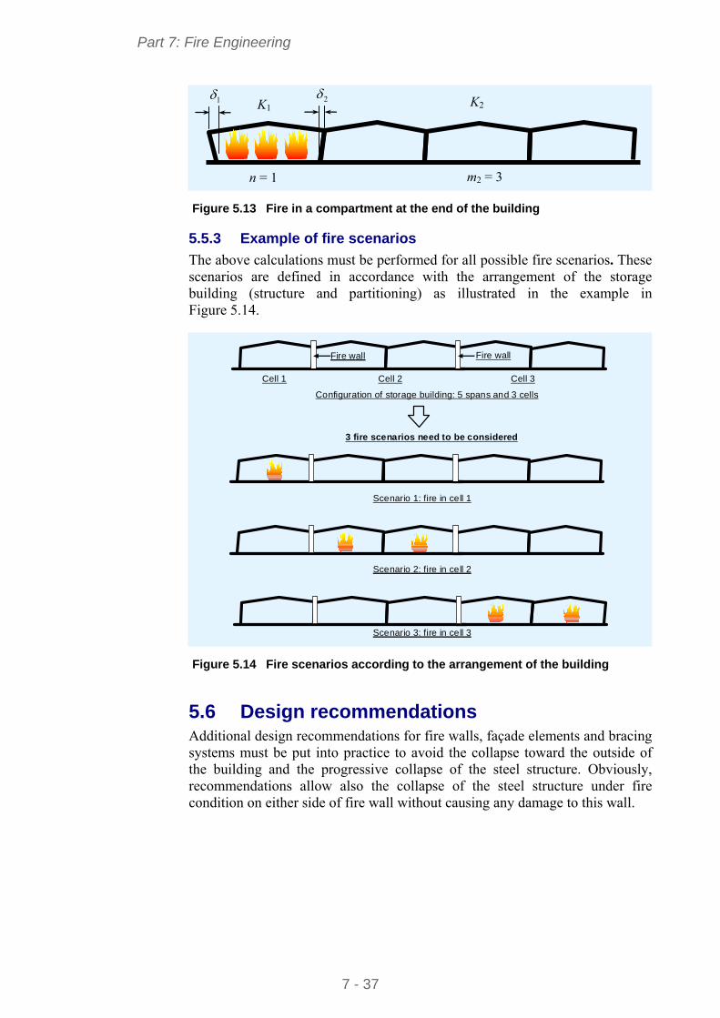
Part 7: Fire Engineering
7 - 37
K1 1 2
n = 1 m2 = 3
K2
Figure 5.13 Fire in a compartment at the end of the building
5.5.3 Example of fire scenarios
The above calculations must be performed for all possible fire scenarios. These scenarios are defined in accordance with the arrangement of the storage building (structure and partitioning) as illustrated in the example in Figure 5.14.
Configuration of storage building: 5 spans and 3 cells
Cell 1 Cell 2 Cell 3
Fire wall Fire wall
Scenario 1: fire in cell 1
Scenario 2: fire in cell 2
Scenario 3: fire in cell 3
3 fire scenarios need to be considered
Figure 5.14 Fire scenarios according to the arrangement of the building
5.6 Design recommendations Additional design recommendations for fire walls, façade elements and bracing systems must be put into practice to avoid the collapse toward the outside of the building and the progressive collapse of the steel structure. Obviously, recommendations allow also the collapse of the steel structure under fire condition on either side of fire wall without causing any damage to this wall.
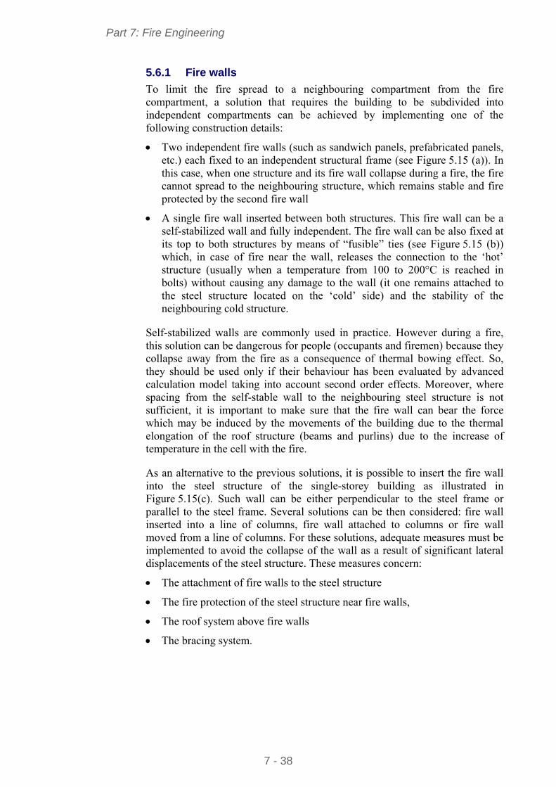
Part 7: Fire Engineering
7 - 38
5.6.1 Fire walls
To limit the fire spread to a neighbouring compartment from the fire compartment, a solution that requires the building to be subdivided into independent compartments can be achieved by implementing one of the following construction details:
Two independent fire walls (such as sandwich panels, prefabricated panels, etc.) each fixed to an independent structural frame (see Figure 5.15 (a)). In this case, when one structure and its fire wall collapse during a fire, the fire cannot spread to the neighbouring structure, which remains stable and fire protected by the second fire wall
A single fire wall inserted between both structures. This fire wall can be a self-stabilized wall and fully independent. The fire wall can be also fixed at its top to both structures by means of “fusible” ties (see Figure 5.15 (b)) which, in case of fire near the wall, releases the connection to the ‘hot’ structure (usually when a temperature from 100 to 200°C is reached in bolts) without causing any damage to the wall (it one remains attached to the steel structure located on the ‘cold’ side) and the stability of the neighbouring cold structure.
Self-stabilized walls are commonly used in practice. However during a fire, this solution can be dangerous for people (occupants and firemen) because they collapse away from the fire as a consequence of thermal bowing effect. So, they should be used only if their behaviour has been evaluated by advanced calculation model taking into account second order effects. Moreover, where spacing from the self-stable wall to the neighbouring steel structure is not sufficient, it is important to make sure that the fire wall can bear the force which may be induced by the movements of the building due to the thermal elongation of the roof structure (beams and purlins) due to the increase of temperature in the cell with the fire.
As an alternative to the previous solutions, it is possible to insert the fire wall into the steel structure of the single-storey building as illustrated in Figure 5.15(c). Such wall can be either perpendicular to the steel frame or parallel to the steel frame. Several solutions can be then considered: fire wall inserted into a line of columns, fire wall attached to columns or fire wall moved from a line of columns. For these solutions, adequate measures must be implemented to avoid the collapse of the wall as a result of significant lateral displacements of the steel structure. These measures concern:
The attachment of fire walls to the steel structure
The fire protection of the steel structure near fire walls,
The roof system above fire walls
The bracing system.
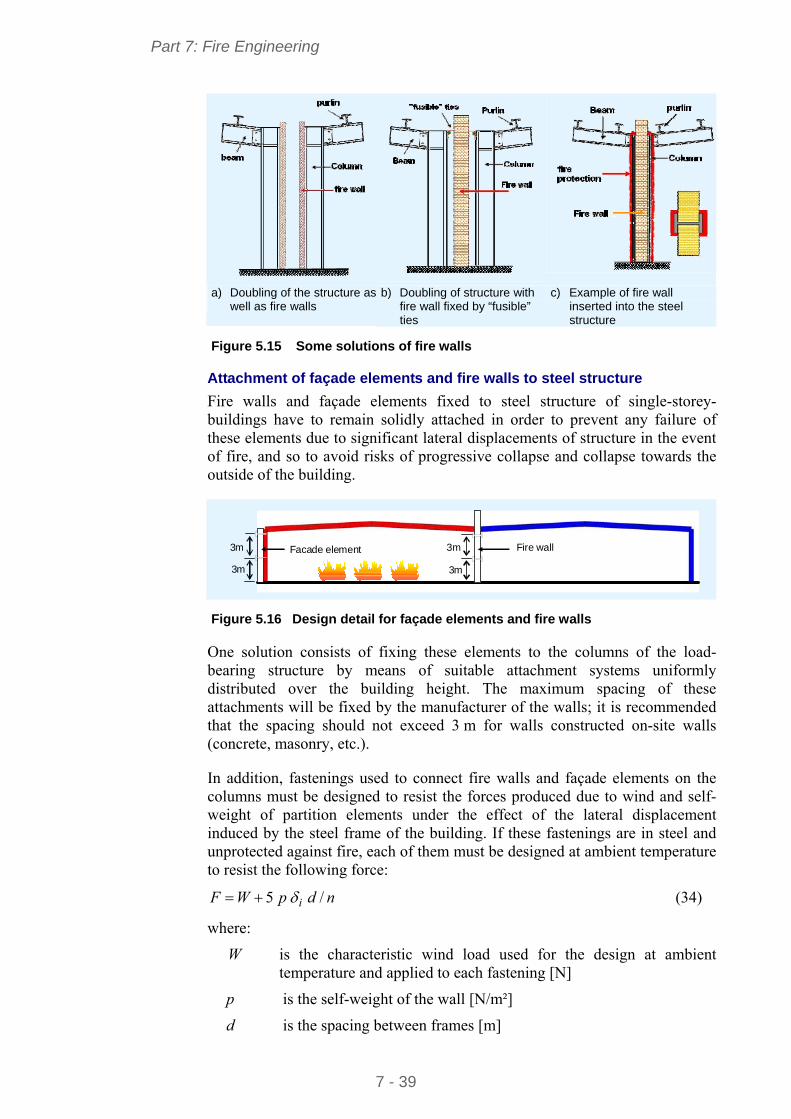
Part 7: Fire Engineering
7 - 39
a) Doubling of the structure as well as fire walls
b) Doubling of structure with fire wall fixed by “fusible” ties
c) Example of fire wall inserted into the steel structure
Figure 5.15 Some solutions of fire walls
Attachment of façade elements and fire walls to steel structure
Fire walls and façade elements fixed to steel structure of single-storey-buildings have to remain solidly attached in order to prevent any failure of these elements due to significant lateral displacements of structure in the event of fire, and so to avoid risks of progressive collapse and collapse towards the outside of the building.
3m
3m
3m
3m
Fire wallFacade element
Figure 5.16 Design detail for façade elements and fire walls
One solution consists of fixing these elements to the columns of the load-bearing structure by means of suitable attachment systems uniformly distributed over the building height. The maximum spacing of these attachments will be fixed by the manufacturer of the walls; it is recommended that the spacing should not exceed 3 m for walls constructed on-site walls (concrete, masonry, etc.).
In addition, fastenings used to connect fire walls and façade elements on the columns must be designed to resist the forces produced due to wind and self-weight of partition elements under the effect of the lateral displacement induced by the steel frame of the building. If these fastenings are in steel and unprotected against fire, each of them must be designed at ambient temperature to resist the following force:
ndpWF i /5 (34)
where:
W is the characteristic wind load used for the design at ambient temperature and applied to each fastening [N]
p is the self-weight of the wall [N/m²]
d is the spacing between frames [m]
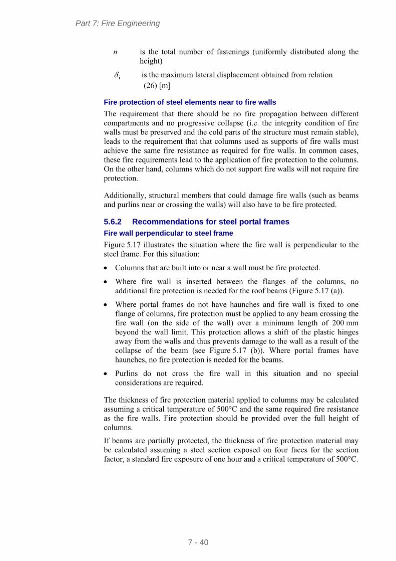
Part 7: Fire Engineering
7 - 40
n is the total number of fastenings (uniformly distributed along the height)
i is the maximum lateral displacement obtained from relation (26) [m]
Fire protection of steel elements near to fire walls
The requirement that there should be no fire propagation between different compartments and no progressive collapse (i.e. the integrity condition of fire walls must be preserved and the cold parts of the structure must remain stable), leads to the requirement that that columns used as supports of fire walls must achieve the same fire resistance as required for fire walls. In common cases, these fire requirements lead to the application of fire protection to the columns. On the other hand, columns which do not support fire walls will not require fire protection.
Additionally, structural members that could damage fire walls (such as beams and purlins near or crossing the walls) will also have to be fire protected.
5.6.2 Recommendations for steel portal frames
Fire wall perpendicular to steel frame
Figure 5.17 illustrates the situation where the fire wall is perpendicular to the steel frame. For this situation:
Columns that are built into or near a wall must be fire protected.
Where fire wall is inserted between the flanges of the columns, no additional fire protection is needed for the roof beams (Figure 5.17 (a)).
Where portal frames do not have haunches and fire wall is fixed to one flange of columns, fire protection must be applied to any beam crossing the fire wall (on the side of the wall) over a minimum length of 200 mm beyond the wall limit. This protection allows a shift of the plastic hinges away from the walls and thus prevents damage to the wall as a result of the collapse of the beam (see Figure 5.17 (b)). Where portal frames have haunches, no fire protection is needed for the beams.
Purlins do not cross the fire wall in this situation and no special considerations are required.
The thickness of fire protection material applied to columns may be calculated assuming a critical temperature of 500°C and the same required fire resistance as the fire walls. Fire protection should be provided over the full height of columns.
If beams are partially protected, the thickness of fire protection material may be calculated assuming a steel section exposed on four faces for the section factor, a standard fire exposure of one hour and a critical temperature of 500°C.
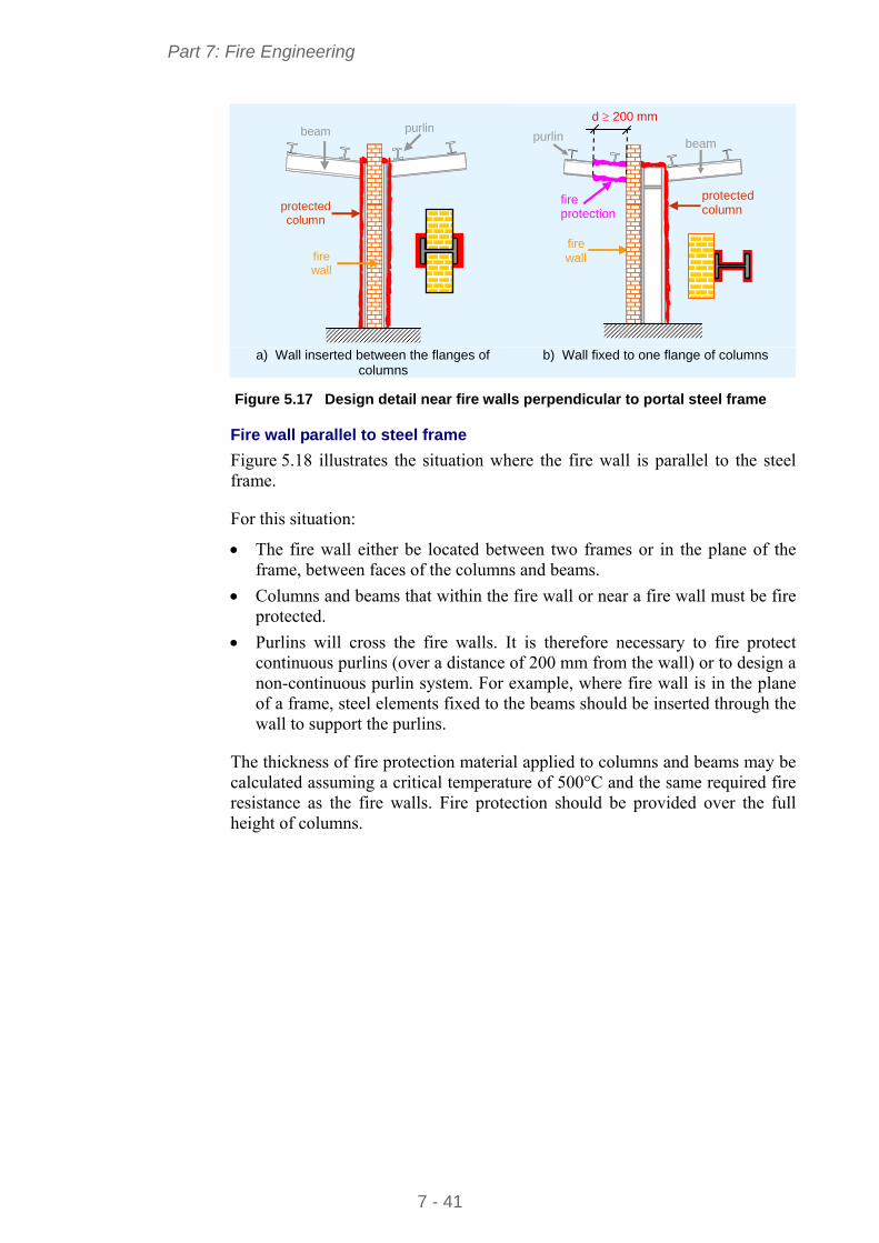
Part 7: Fire Engineering
7 - 41
beam purlin
fire wall
protected column
purlin
fire wall
protected column
fire protection
d 200 mm
beam
a) Wall inserted between the flanges of
columns b) Wall fixed to one flange of columns
Figure 5.17 Design detail near fire walls perpendicular to portal steel frame
Fire wall parallel to steel frame
Figure 5.18 illustrates the situation where the fire wall is parallel to the steel frame.
For this situation:
The fire wall either be located between two frames or in the plane of the frame, between faces of the columns and beams.
Columns and beams that within the fire wall or near a fire wall must be fire protected.
Purlins will cross the fire walls. It is therefore necessary to fire protect continuous purlins (over a distance of 200 mm from the wall) or to design a non-continuous purlin system. For example, where fire wall is in the plane of a frame, steel elements fixed to the beams should be inserted through the wall to support the purlins.
The thickness of fire protection material applied to columns and beams may be calculated assuming a critical temperature of 500°C and the same required fire resistance as the fire walls. Fire protection should be provided over the full height of columns.
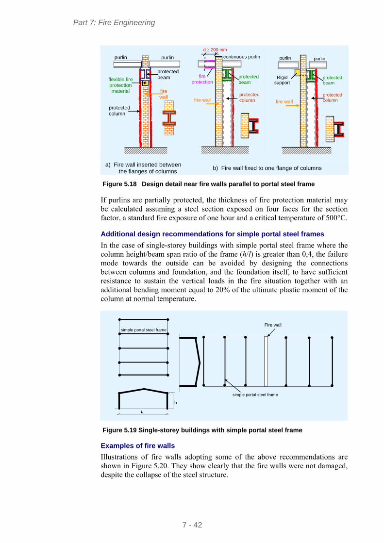
Part 7: Fire Engineering
7 - 42
fire wall
protected beam
purlin
protected column
purlin
flexible fire protection material
continuous purlin
protected beam
d 200 mm
protected column fire wall
fire protection
purlin
Rigid support
fire wall
purlin
protected beam
protected column
a) Fire wall inserted between the flanges of columns
b) Fire wall fixed to one flange of columns
Figure 5.18 Design detail near fire walls parallel to portal steel frame
If purlins are partially protected, the thickness of fire protection material may be calculated assuming a steel section exposed on four faces for the section factor, a standard fire exposure of one hour and a critical temperature of 500°C.
Additional design recommendations for simple portal steel frames
In the case of single-storey buildings with simple portal steel frame where the column height/beam span ratio of the frame (h/l) is greater than 0,4, the failure mode towards the outside can be avoided by designing the connections between columns and foundation, and the foundation itself, to have sufficient resistance to sustain the vertical loads in the fire situation together with an additional bending moment equal to 20% of the ultimate plastic moment of the column at normal temperature.
Fire wall
simple portal steel frame
simple portal steel frame
h
L
Figure 5.19 Single-storey buildings with simple portal steel frame
Examples of fire walls
Illustrations of fire walls adopting some of the above recommendations are shown in Figure 5.20. They show clearly that the fire walls were not damaged, despite the collapse of the steel structure.
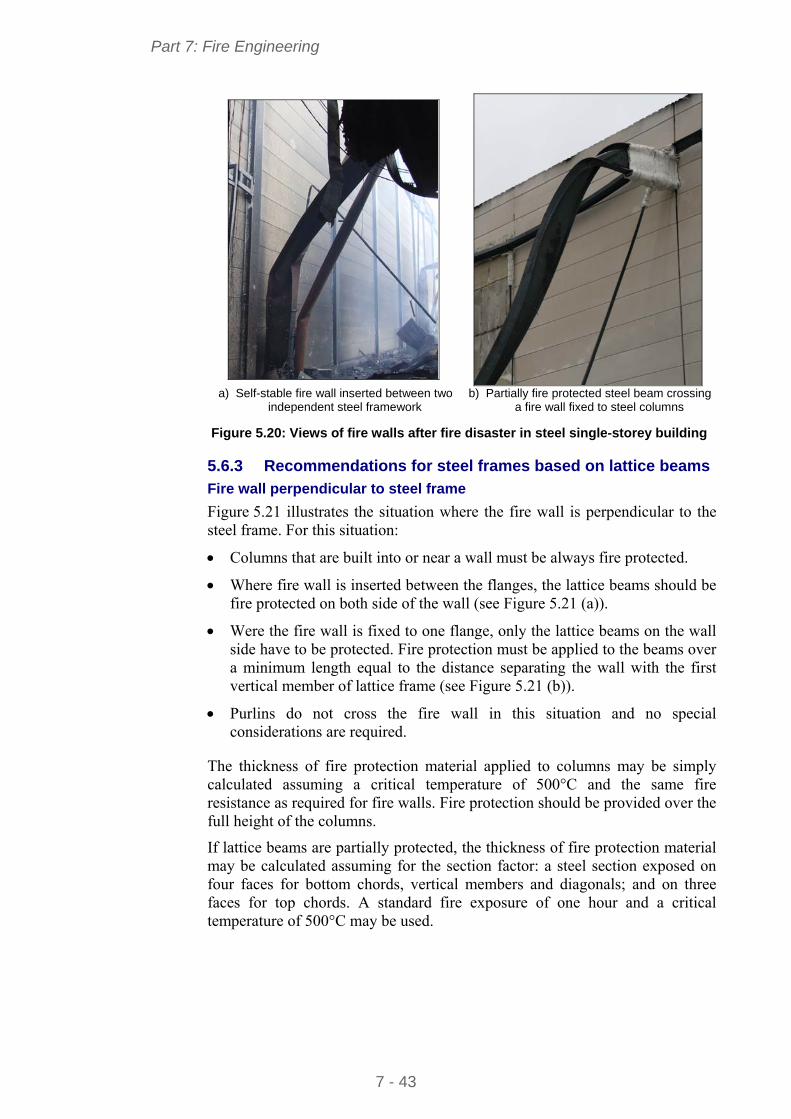
Part 7: Fire Engineering
7 - 43
a) Self-stable fire wall inserted between two
independent steel framework b) Partially fire protected steel beam crossing
a fire wall fixed to steel columns Figure 5.20: Views of fire walls after fire disaster in steel single-storey building
5.6.3 Recommendations for steel frames based on lattice beams
Fire wall perpendicular to steel frame
Figure 5.21 illustrates the situation where the fire wall is perpendicular to the steel frame. For this situation:
Columns that are built into or near a wall must be always fire protected.
Where fire wall is inserted between the flanges, the lattice beams should be fire protected on both side of the wall (see Figure 5.21 (a)).
Were the fire wall is fixed to one flange, only the lattice beams on the wall side have to be protected. Fire protection must be applied to the beams over a minimum length equal to the distance separating the wall with the first vertical member of lattice frame (see Figure 5.21 (b)).
Purlins do not cross the fire wall in this situation and no special considerations are required.
The thickness of fire protection material applied to columns may be simply calculated assuming a critical temperature of 500°C and the same fire resistance as required for fire walls. Fire protection should be provided over the full height of the columns.
If lattice beams are partially protected, the thickness of fire protection material may be calculated assuming for the section factor: a steel section exposed on four faces for bottom chords, vertical members and diagonals; and on three faces for top chords. A standard fire exposure of one hour and a critical temperature of 500°C may be used.
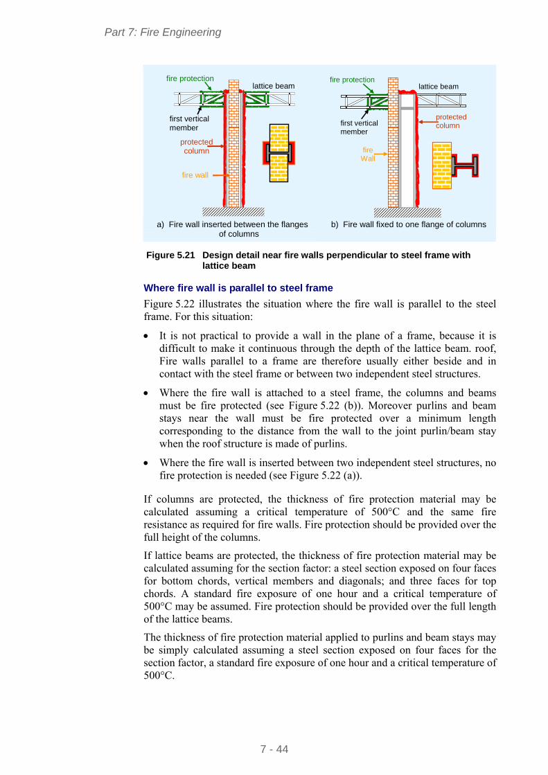
Part 7: Fire Engineering
7 - 44
first vertical member
fire wall
protected column
fire protection lattice beam
fire Wall
protected column
fire protection
first vertical member
lattice beam
a) Fire wall inserted between the flanges
of columns
b) Fire wall fixed to one flange of columns
Figure 5.21 Design detail near fire walls perpendicular to steel frame with
lattice beam
Where fire wall is parallel to steel frame
Figure 5.22 illustrates the situation where the fire wall is parallel to the steel frame. For this situation:
It is not practical to provide a wall in the plane of a frame, because it is difficult to make it continuous through the depth of the lattice beam. roof, Fire walls parallel to a frame are therefore usually either beside and in contact with the steel frame or between two independent steel structures.
Where the fire wall is attached to a steel frame, the columns and beams must be fire protected (see Figure 5.22 (b)). Moreover purlins and beam stays near the wall must be fire protected over a minimum length corresponding to the distance from the wall to the joint purlin/beam stay when the roof structure is made of purlins.
Where the fire wall is inserted between two independent steel structures, no fire protection is needed (see Figure 5.22 (a)).
If columns are protected, the thickness of fire protection material may be calculated assuming a critical temperature of 500°C and the same fire resistance as required for fire walls. Fire protection should be provided over the full height of the columns.
If lattice beams are protected, the thickness of fire protection material may be calculated assuming for the section factor: a steel section exposed on four faces for bottom chords, vertical members and diagonals; and three faces for top chords. A standard fire exposure of one hour and a critical temperature of 500°C may be assumed. Fire protection should be provided over the full length of the lattice beams.
The thickness of fire protection material applied to purlins and beam stays may be simply calculated assuming a steel section exposed on four faces for the section factor, a standard fire exposure of one hour and a critical temperature of 500°C.
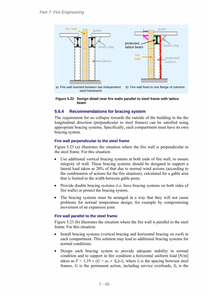
Part 7: Fire Engineering
7 - 45
purlin fire wall
beam stay
column
protected column
purlin
fire wall
protected lattice beam
beam stay
a) Fire wall inserted between two independent
steel framework
b) Fire wall fixed to one flange of columns
Figure 5.22 Design detail near fire walls parallel to steel frame with lattice
beam
5.6.4 Recommendations for bracing system
The requirement for no collapse towards the outside of the building in the the longitudinal direction (perpendicular to steel frames) can be satisfied using appropriate bracing systems. Specifically, each compartment must have its own bracing system.
Fire wall perpendicular to the steel frame
Figure 5.23 (a) illustrates the situation where the fire wall is perpendicular to the steel frame. For this situation:
Use additional vertical bracing systems at both ends of fire wall, to ensure integrity of wall. These bracing systems should be designed to support a lateral load taken as 20% of that due to normal wind actions (according to the combination of actions for the fire situation), calculated for a gable area that is limited to the width between gable posts.
Provide double bracing systems (i.e. have bracing systems on both sides of fire walls) or protect the bracing system.
The bracing systems must be arranged in a way that they will not cause problems for normal temperature design, for example by compromising movement of an expansion joint.
Fire wall parallel to the steel frame
Figure 5.23 (b) illustrates the situation where the fire wall is parallel to the steel frame. For this situation:
Install bracing systems (vertical bracing and horizontal bracing on roof) in each compartment. This solution may lead to additional bracing systems for normal conditions.
Design each bracing system to provide adequate stability in normal condition and to support in fire condition a horizontal uniform load [N/m] taken as F = 1,19 (G + ψ1 Sn)lf, where lf is the spacing between steel frames, G is the permanent action, including service overloads, Sn is the
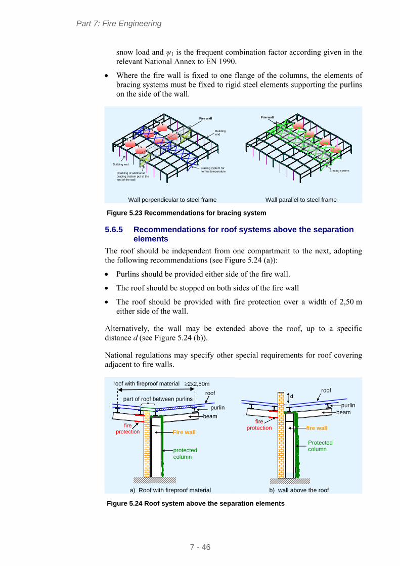
Part 7: Fire Engineering
7 - 46
snow load and ψ1 is the frequent combination factor according given in the relevant National Annex to EN 1990.
Where the fire wall is fixed to one flange of the columns, the elements of bracing systems must be fixed to rigid steel elements supporting the purlins on the side of the wall.
Fire wall
Building end
Doubling of additional bracing system put at the end of fire wall
Bracing system for normal temperature
Building end
Wall perpendicular to steel frame
Fire wall
Bracing system
Wall parallel to steel frame
Figure 5.23 Recommendations for bracing system
5.6.5 Recommendations for roof systems above the separation elements
The roof should be independent from one compartment to the next, adopting the following recommendations (see Figure 5.24 (a)):
Purlins should be provided either side of the fire wall.
The roof should be stopped on both sides of the fire wall
The roof should be provided with fire protection over a width of 2,50 m either side of the wall.
Alternatively, the wall may be extended above the roof, up to a specific distance d (see Figure 5.24 (b)).
National regulations may specify other special requirements for roof covering adjacent to fire walls.
protected column
Fire wall
beam
purlin
roof with fireproof material 2x2,50m
roof
part of roof between purlins
fire protection
Protected column
fire wall beam
purlin
roof
d
fire protection
a) Roof with fireproof material b) wall above the roof
Figure 5.24 Roof system above the separation elements
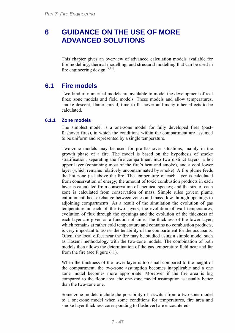
Part 7: Fire Engineering
7 - 47
6 GUIDANCE ON THE USE OF MORE ADVANCED SOLUTIONS
This chapter gives an overview of advanced calculation models available for fire modelling, thermal modelling, and structural modelling that can be used in fire engineering design [9,16].
6.1 Fire models Two kind of numerical models are available to model the development of real fires: zone models and field models. These models and allow temperatures, smoke descent, flame spread, time to flashover and many other effects to be calculated.
6.1.1 Zone models
The simplest model is a one-zone model for fully developed fires (post-flashover fires), in which the conditions within the compartment are assumed to be uniform and represented by a single temperature.
Two-zone models may be used for pre-flashover situations, mainly in the growth phase of a fire. The model is based on the hypothesis of smoke stratification, separating the fire compartment into two distinct layers: a hot upper layer (containing most of the fire’s heat and smoke), and a cool lower layer (which remains relatively uncontaminated by smoke). A fire plume feeds the hot zone just above the fire. The temperature of each layer is calculated from conservation of energy; the amount of toxic combustion products in each layer is calculated from conservation of chemical species; and the size of each zone is calculated from conservation of mass. Simple rules govern plume entrainment, heat exchange between zones and mass flow through openings to adjoining compartments. As a result of the simulation the evolution of gas temperature in each of the two layers, the evolution of wall temperatures, evolution of flux through the openings and the evolution of the thickness of each layer are given as a function of time. The thickness of the lower layer, which remains at rather cold temperature and contains no combustion products, is very important to assess the tenability of the compartment for the occupants. Often, the local effect near the fire may be studied using a simple model such as Hasemi methodology with the two-zone models. The combination of both models then allows the determination of the gas temperature field near and far from the fire (see Figure 6.1).
When the thickness of the lower layer is too small compared to the height of the compartment, the two-zone assumption becomes inapplicable and a one zone model becomes more appropriate. Moreover if the fire area is big compared to the floor area, the one-zone model assumption is usually better than the two-zone one.
Some zone models include the possibility of a switch from a two-zone model to a one-zone model when some conditions for temperatures, fire area and smoke layer thickness corresponding to flashover) are encountered.
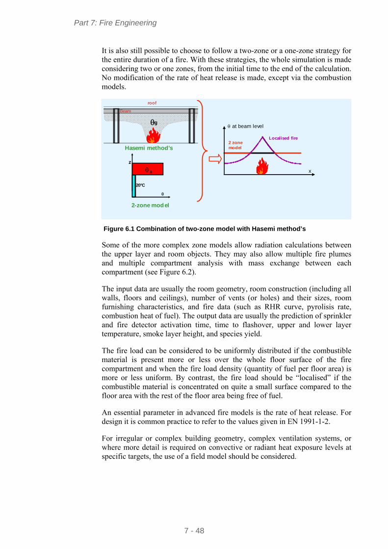
Part 7: Fire Engineering
7 - 48
It is also still possible to choose to follow a two-zone or a one-zone strategy for the entire duration of a fire. With these strategies, the whole simulation is made considering two or one zones, from the initial time to the end of the calculation. No modification of the rate of heat release is made, except via the combustion models.
Localised fire 2 zone model
roof
g
Beam
Hasemi method’s
20°C
z
g
2-zone model
at beam level
x
Figure 6.1 Combination of two-zone model with Hasemi method’s
Some of the more complex zone models allow radiation calculations between the upper layer and room objects. They may also allow multiple fire plumes and multiple compartment analysis with mass exchange between each compartment (see Figure 6.2).
The input data are usually the room geometry, room construction (including all walls, floors and ceilings), number of vents (or holes) and their sizes, room furnishing characteristics, and fire data (such as RHR curve, pyrolisis rate, combustion heat of fuel). The output data are usually the prediction of sprinkler and fire detector activation time, time to flashover, upper and lower layer temperature, smoke layer height, and species yield.
The fire load can be considered to be uniformly distributed if the combustible material is present more or less over the whole floor surface of the fire compartment and when the fire load density (quantity of fuel per floor area) is more or less uniform. By contrast, the fire load should be “localised” if the combustible material is concentrated on quite a small surface compared to the floor area with the rest of the floor area being free of fuel.
An essential parameter in advanced fire models is the rate of heat release. For design it is common practice to refer to the values given in EN 1991-1-2.
For irregular or complex building geometry, complex ventilation systems, or where more detail is required on convective or radiant heat exposure levels at specific targets, the use of a field model should be considered.
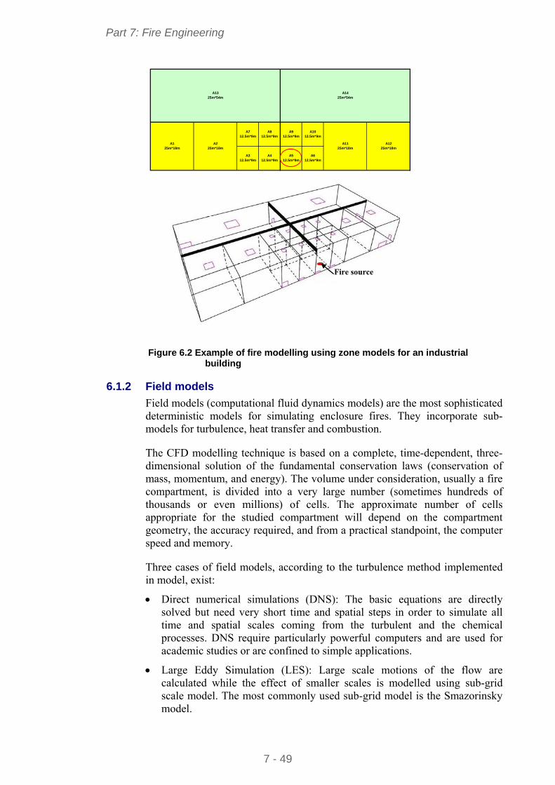
Part 7: Fire Engineering
7 - 49
A712.5m*9m
A1325m*54m
A312.5m*9m
A412.5m*9m
A812.5m*9m
A225m*18m
A125m*18m
A1225m*18m
A912.5m*9m
A1425m*54m
A1012.5m*9m
A512.5m*9m
A612.5m*9m
A1125m*18m
Fire source
Figure 6.2 Example of fire modelling using zone models for an industrial
building
6.1.2 Field models
Field models (computational fluid dynamics models) are the most sophisticated deterministic models for simulating enclosure fires. They incorporate sub-models for turbulence, heat transfer and combustion.
The CFD modelling technique is based on a complete, time-dependent, three-dimensional solution of the fundamental conservation laws (conservation of mass, momentum, and energy). The volume under consideration, usually a fire compartment, is divided into a very large number (sometimes hundreds of thousands or even millions) of cells. The approximate number of cells appropriate for the studied compartment will depend on the compartment geometry, the accuracy required, and from a practical standpoint, the computer speed and memory.
Three cases of field models, according to the turbulence method implemented in model, exist:
Direct numerical simulations (DNS): The basic equations are directly solved but need very short time and spatial steps in order to simulate all time and spatial scales coming from the turbulent and the chemical processes. DNS require particularly powerful computers and are used for academic studies or are confined to simple applications.
Large Eddy Simulation (LES): Large scale motions of the flow are calculated while the effect of smaller scales is modelled using sub-grid scale model. The most commonly used sub-grid model is the Smazorinsky model.
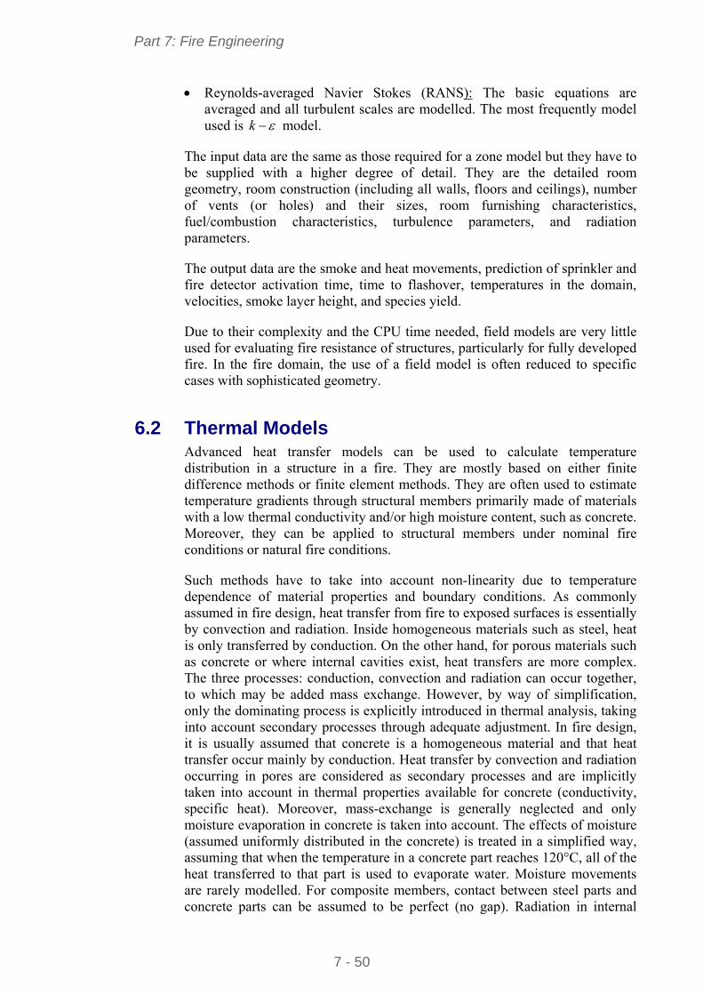
Part 7: Fire Engineering
7 - 50
Reynolds-averaged Navier Stokes (RANS): The basic equations are averaged and all turbulent scales are modelled. The most frequently model used is k model.
The input data are the same as those required for a zone model but they have to be supplied with a higher degree of detail. They are the detailed room geometry, room construction (including all walls, floors and ceilings), number of vents (or holes) and their sizes, room furnishing characteristics, fuel/combustion characteristics, turbulence parameters, and radiation parameters.
The output data are the smoke and heat movements, prediction of sprinkler and fire detector activation time, time to flashover, temperatures in the domain, velocities, smoke layer height, and species yield.
Due to their complexity and the CPU time needed, field models are very little used for evaluating fire resistance of structures, particularly for fully developed fire. In the fire domain, the use of a field model is often reduced to specific cases with sophisticated geometry.
6.2 Thermal Models Advanced heat transfer models can be used to calculate temperature distribution in a structure in a fire. They are mostly based on either finite difference methods or finite element methods. They are often used to estimate temperature gradients through structural members primarily made of materials with a low thermal conductivity and/or high moisture content, such as concrete. Moreover, they can be applied to structural members under nominal fire conditions or natural fire conditions.
Such methods have to take into account non-linearity due to temperature dependence of material properties and boundary conditions. As commonly assumed in fire design, heat transfer from fire to exposed surfaces is essentially by convection and radiation. Inside homogeneous materials such as steel, heat is only transferred by conduction. On the other hand, for porous materials such as concrete or where internal cavities exist, heat transfers are more complex. The three processes: conduction, convection and radiation can occur together, to which may be added mass exchange. However, by way of simplification, only the dominating process is explicitly introduced in thermal analysis, taking into account secondary processes through adequate adjustment. In fire design, it is usually assumed that concrete is a homogeneous material and that heat transfer occur mainly by conduction. Heat transfer by convection and radiation occurring in pores are considered as secondary processes and are implicitly taken into account in thermal properties available for concrete (conductivity, specific heat). Moreover, mass-exchange is generally neglected and only moisture evaporation in concrete is taken into account. The effects of moisture (assumed uniformly distributed in the concrete) is treated in a simplified way, assuming that when the temperature in a concrete part reaches 120°C, all of the heat transferred to that part is used to evaporate water. Moisture movements are rarely modelled. For composite members, contact between steel parts and concrete parts can be assumed to be perfect (no gap). Radiation in internal
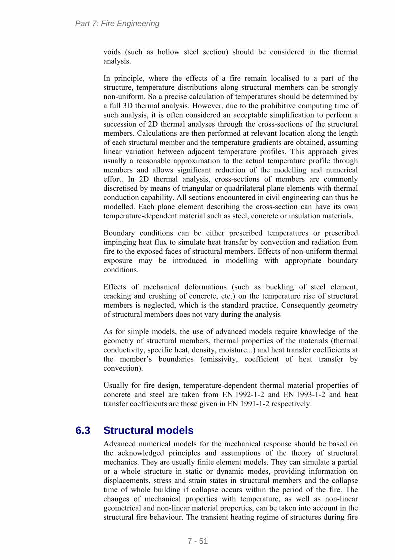
Part 7: Fire Engineering
7 - 51
voids (such as hollow steel section) should be considered in the thermal analysis.
In principle, where the effects of a fire remain localised to a part of the structure, temperature distributions along structural members can be strongly non-uniform. So a precise calculation of temperatures should be determined by a full 3D thermal analysis. However, due to the prohibitive computing time of such analysis, it is often considered an acceptable simplification to perform a succession of 2D thermal analyses through the cross-sections of the structural members. Calculations are then performed at relevant location along the length of each structural member and the temperature gradients are obtained, assuming linear variation between adjacent temperature profiles. This approach gives usually a reasonable approximation to the actual temperature profile through members and allows significant reduction of the modelling and numerical effort. In 2D thermal analysis, cross-sections of members are commonly discretised by means of triangular or quadrilateral plane elements with thermal conduction capability. All sections encountered in civil engineering can thus be modelled. Each plane element describing the cross-section can have its own temperature-dependent material such as steel, concrete or insulation materials.
Boundary conditions can be either prescribed temperatures or prescribed impinging heat flux to simulate heat transfer by convection and radiation from fire to the exposed faces of structural members. Effects of non-uniform thermal exposure may be introduced in modelling with appropriate boundary conditions.
Effects of mechanical deformations (such as buckling of steel element, cracking and crushing of concrete, etc.) on the temperature rise of structural members is neglected, which is the standard practice. Consequently geometry of structural members does not vary during the analysis
As for simple models, the use of advanced models require knowledge of the geometry of structural members, thermal properties of the materials (thermal conductivity, specific heat, density, moisture...) and heat transfer coefficients at the member’s boundaries (emissivity, coefficient of heat transfer by convection).
Usually for fire design, temperature-dependent thermal material properties of concrete and steel are taken from EN 1992-1-2 and EN 1993-1-2 and heat transfer coefficients are those given in EN 1991-1-2 respectively.
6.3 Structural models Advanced numerical models for the mechanical response should be based on the acknowledged principles and assumptions of the theory of structural mechanics. They are usually finite element models. They can simulate a partial or a whole structure in static or dynamic modes, providing information on displacements, stress and strain states in structural members and the collapse time of whole building if collapse occurs within the period of the fire. The changes of mechanical properties with temperature, as well as non-linear geometrical and non-linear material properties, can be taken into account in the structural fire behaviour. The transient heating regime of structures during fire
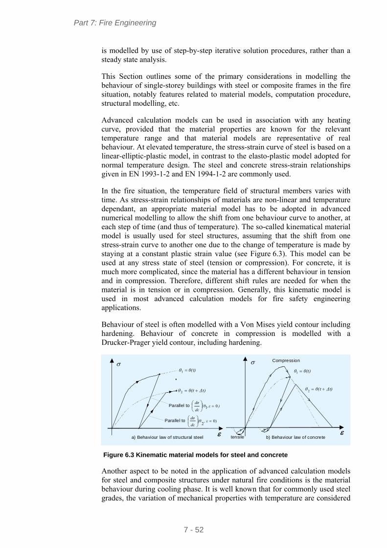
Part 7: Fire Engineering
7 - 52
is modelled by use of step-by-step iterative solution procedures, rather than a steady state analysis.
This Section outlines some of the primary considerations in modelling the behaviour of single-storey buildings with steel or composite frames in the fire situation, notably features related to material models, computation procedure, structural modelling, etc.
Advanced calculation models can be used in association with any heating curve, provided that the material properties are known for the relevant temperature range and that material models are representative of real behaviour. At elevated temperature, the stress-strain curve of steel is based on a linear-elliptic-plastic model, in contrast to the elasto-plastic model adopted for normal temperature design. The steel and concrete stress-strain relationships given in EN 1993-1-2 and EN 1994-1-2 are commonly used.
In the fire situation, the temperature field of structural members varies with time. As stress-strain relationships of materials are non-linear and temperature dependant, an appropriate material model has to be adopted in advanced numerical modelling to allow the shift from one behaviour curve to another, at each step of time (and thus of temperature). The so-called kinematical material model is usually used for steel structures, assuming that the shift from one stress-strain curve to another one due to the change of temperature is made by staying at a constant plastic strain value (see Figure 6.3). This model can be used at any stress state of steel (tension or compression). For concrete, it is much more complicated, since the material has a different behaviour in tension and in compression. Therefore, different shift rules are needed for when the material is in tension or in compression. Generally, this kinematic model is used in most advanced calculation models for fire safety engineering applications.
Behaviour of steel is often modelled with a Von Mises yield contour including hardening. Behaviour of concrete in compression is modelled with a Drucker-Prager yield contour, including hardening.
),ε(θdε
dσ01
θ(t)θ 1
Δt)θ(tθ 2
a) Behaviour law of structural steel
Parallel to
)02
, ε(θdε
dσParallel to
Compression
b) Behaviour law of concrete
θ(t)θ 1
Δt)θ(tθ 2
tensile
Figure 6.3 Kinematic material models for steel and concrete
Another aspect to be noted in the application of advanced calculation models for steel and composite structures under natural fire conditions is the material behaviour during cooling phase. It is well known that for commonly used steel grades, the variation of mechanical properties with temperature are considered
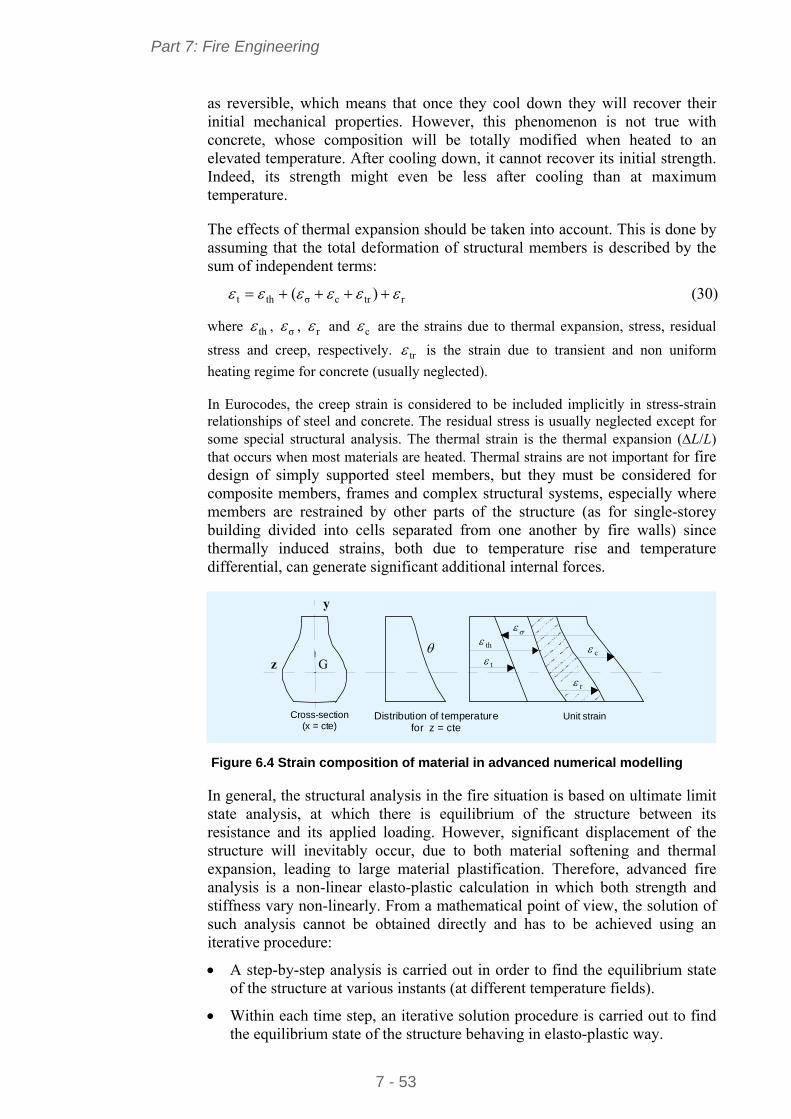
Part 7: Fire Engineering
7 - 53
as reversible, which means that once they cool down they will recover their initial mechanical properties. However, this phenomenon is not true with concrete, whose composition will be totally modified when heated to an elevated temperature. After cooling down, it cannot recover its initial strength. Indeed, its strength might even be less after cooling than at maximum temperature.
The effects of thermal expansion should be taken into account. This is done by assuming that the total deformation of structural members is described by the sum of independent terms:
rtrcσtht )( (30)
where th , σ , r and c are the strains due to thermal expansion, stress, residual
stress and creep, respectively. tr is the strain due to transient and non uniform
heating regime for concrete (usually neglected).
In Eurocodes, the creep strain is considered to be included implicitly in stress-strain relationships of steel and concrete. The residual stress is usually neglected except for some special structural analysis. The thermal strain is the thermal expansion (L/L) that occurs when most materials are heated. Thermal strains are not important for fire design of simply supported steel members, but they must be considered for composite members, frames and complex structural systems, especially where members are restrained by other parts of the structure (as for single-storey building divided into cells separated from one another by fire walls) since thermally induced strains, both due to temperature rise and temperature differential, can generate significant additional internal forces.
Distribution of temperaturefor z = cte
Unit strain Cross-section(x = cte)
z
y
G c
th
t
r
Figure 6.4 Strain composition of material in advanced numerical modelling
In general, the structural analysis in the fire situation is based on ultimate limit state analysis, at which there is equilibrium of the structure between its resistance and its applied loading. However, significant displacement of the structure will inevitably occur, due to both material softening and thermal expansion, leading to large material plastification. Therefore, advanced fire analysis is a non-linear elasto-plastic calculation in which both strength and stiffness vary non-linearly. From a mathematical point of view, the solution of such analysis cannot be obtained directly and has to be achieved using an iterative procedure:
A step-by-step analysis is carried out in order to find the equilibrium state of the structure at various instants (at different temperature fields).
Within each time step, an iterative solution procedure is carried out to find the equilibrium state of the structure behaving in elasto-plastic way.
Part 7: Fire Engineering
7 - 54
Different types of convergence procedure are usually employed, such as the pure Newton-Raphson procedure and the modified Newton-Raphson procedure. The pure Newton-Raphson procedure is recommended for structures made of beam elements, and the modified Newton-Raphson procedure is recommended for structures made of shell elements.
Static analysis is normally sufficient for modelling the behaviour of a structure in fire. However, local failure or instability of a structural member (such as lateral buckling of purlin) does not lead to overall structural failure. Consequently, analysis should be performed by a succession of subsequent static and dynamic analyses to pass instabilities and to obtain the complete failure mechanism to predict the influence of a local failure on the global behaviour of the structure and to follow eventually progressive collapse. It has to be kept in mind that here the aim is not the precise modelling of dynamic effects. So, default values of the main parameters fixed in models to determinate acceleration and damping effects can be used.
Existing boundary conditions should be rightly represented. It is common to design structure by assuming pinned support conditions at the column bases. However, as fully pinned bases of columns are never achieved in reality, it is also possible, when data are available, to introduce semi-rigid connections. Where only a part of the structure is modelled, some restrained conditions from unmodelled part of the structure should be taken into consideration in appropriate way. The choices of restrained conditions that have to be applied at the boundaries between the modelled substructure and the rest of the structure have to be chosen by the designer. For example, in case of symmetry boundary, restraints to translation across the symmetry boundary and rotational restraint about the two major axes on the plane of symmetry are introduced in modelling.
Usually, beam-to-column joints are assumed to be fully rigid in the fire design of steel and steel-concrete composite frames. However, in the case of steel frames based on lattice beams, joints between members of lattice beams and connections between top and bottom chords of lattice beams and columns can be assumed pinned or fully rigid according to the type of truss.
Two types of action need to be applied to heated structures. The first type is static loading. It must correspond to that for fire situation. The second type consists of the temperature increase (above ambient) of the structural members obtained, from previous thermal analysis. Boundary conditions at supports as well as applied gravity loads are assumed to remain unchanged throughout the fire exposure
It is important to choose an appropriate structural modelling strategy. Simulation of the mechanical behaviour of single-storey building in fire conditions can be performed either by a 2D or a 3D analysis.
In a 2D analysis, simulation are performed in the plane of each portal frame, assuming a three dimensional behaviour of the frame to take into account the lateral instability of the members (columns, beams). In such modelling, adequate restraint conditions should be introduced to stabilize the frame laterally. In reality, these out-of-plane restraints are provided by roof structure
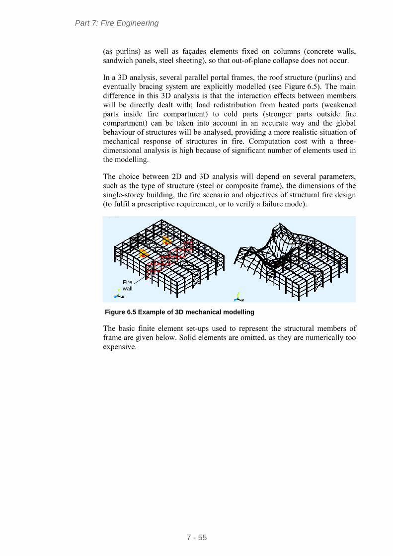
Part 7: Fire Engineering
7 - 55
(as purlins) as well as façades elements fixed on columns (concrete walls, sandwich panels, steel sheeting), so that out-of-plane collapse does not occur.
In a 3D analysis, several parallel portal frames, the roof structure (purlins) and eventually bracing system are explicitly modelled (see Figure 6.5). The main difference in this 3D analysis is that the interaction effects between members will be directly dealt with; load redistribution from heated parts (weakened parts inside fire compartment) to cold parts (stronger parts outside fire compartment) can be taken into account in an accurate way and the global behaviour of structures will be analysed, providing a more realistic situation of mechanical response of structures in fire. Computation cost with a three-dimensional analysis is high because of significant number of elements used in the modelling.
The choice between 2D and 3D analysis will depend on several parameters, such as the type of structure (steel or composite frame), the dimensions of the single-storey building, the fire scenario and objectives of structural fire design (to fulfil a prescriptive requirement, or to verify a failure mode).
Fire wall
Figure 6.5 Example of 3D mechanical modelling
The basic finite element set-ups used to represent the structural members of frame are given below. Solid elements are omitted. as they are numerically too expensive.
Part 7: Fire Engineering
7 - 56
REFERENCES
1 EN 1991-1-2:2002 Eurocode 1: Actions on structures - Part 1-2: General rules - Actions on structures exposed to fire
2 EN 1993-1-2:2003 Eurocode 3: Design of steel structures - Part 1-2: General rules – Structural fire design
3 EN 1994-1-2:2003 Eurocode 4: Design of composite steel and concrete structures – Part 1-2: General rules - Actions on structures exposed to fire
4 HOCKEY, S.M., and REW, P.J. Human response to thermal radiation HSE Books, UK, 1996.
5 VASSART, O., CAJOT, L-G., ZHAO, B., DE LA QUINTA, J.MARTINEZ DE ARAGON, J. and GRIFFIN, A. Fire Safety of industrial halls and low-rise buildings: Realistic fire design, active safety measures, post-local failure simulation and performance based requirements ECSC research project 7210-PR-378.
6 RFCS Research: Fire safety of industrial hall, Design Guide, Arcelor Mittal, CTICM, Labein tecnalia, ULG, Directorate-General for research, Research Fund for Coal and Steel Unit, RFS2-CR-2007-00032, Luxembourg, 2007.
7 Report to ECCS: Fire building regulations for single-storey buildings in 9 European countries. Document RT915. Version 02 June 2002.
8 LENNON, T., MOORE,D., WANG, B. Y. C. and BAILEY, G. Designers’ Guide to EN 1991-1-2, EN 1992- 1-2, EN 1993-1-2 and EN 1994-1-2 Actions on Structures Exposed to Fire and Structural Fire Design Thomas Telford, 2007.
9 DIFISEK - Dissemination of Structural Fire Safety Engineering Knowledge ECSC research project RFS-C2-03048.
10 PURKISS, J.A. Fire safety design of structures Butterworth-Heinemann, Oxford, UK
11 Risk Based Fire Resistance Requirements Competitive (RISK -REI), ECSC research project 7210-PR-378.
12 SIMMS, W.I., and NEWMAN, G.M. Single-storey steel framed building in fire boundary conditions (P313) The Steel Construction Institute, 2002.
13 ECCS TC3: Euro-monograms for fire exposed steelwork.
14 SD005a-EN-EU, Data: Nomogram for protected members, www.steel-access.com
15 RFCS Research: Fire safety of industrial hall, Design Guide, Arcelor Mittal, CTICM, Labein tecnalia, ULG, Directorate-General for research, Research Fund for Coal and Steel Unit, RFS2-CR-2007-00032, Luxembourg, 2007.
16 FRANSSEN J. M., KODUR V. and ZAHARIA R. Designing steel structures for fire safety Balkema Book, 2009.
Part 7: Fire Engineering
7 - 57
APPENDIX A German fire safety procedure for single-storey industrial and commercial buildings In Germany, buildings for commercial and industrial use must conform to the “Musterbauordnung” (MBO) and to all federal state building regulations “Bauliche Anlagen und Räume besonderer Art und Nutzung” (“Structural facilities and spaces with special requirements and uses”). In such cases, and in order to meet essential requirements (concerning human safety, public security, and protection of the natural environment), it is possible to adopt alternative solutions to the prescriptive federal state building regulations.
This general statement has to be considered in the context of physical and technical fire protection requirements for a building with reference to of “Wohngebäude und vergleichbare Nutzungen” (“residential and similar uses”) according to the federal state building regulations. For commercial and industrial uses, it is neither necessary nor appropriate to apply the requirements of the federal state building regulations. When it comes to meeting general structural fire protection objectives, it is more important to consider each building on an individual basis.
A standard procedure for assessing requirements, using scientifically based methods, is recommended.
Since industrial buildings are considered “Sonderbauten” (“special buildings”) within the definition of §51 Abs.1 MBO and cannot usually be exempt from the applicable regulations, the goal of MIndBauRl (the technical construction regulation) is to determine the minimum requirements for structural fire prevention. The MIndBauRl also uses design procedures according DIN 18230-1: Structural fire protection in industrial buildings –fire resistance design.
Regarding §3 Abs. 3, Satz 3 MBO, which permits variations from technical construction standards, the procedure limits this to accepted methods for fire protection engineering and requires that these are listed in accordance with Annex 1.
The aim of the procedure is to regulate the minimum requirements for fire protection of industrial buildings, in particular regarding:
the fire resistance of components and the flammability of building materials
the size of fire compartments and fire-fighting areas
the availability, location and length of emergency escape routes.
The procedure will facilitate design for building owners, designers, draftsmen and specialists; for the authorities it will provide justification for relaxation or deviation from the alternatively applicable rules of the MBO. It offers building control and approval bodies a benchmark for equivalent risks. A design method that requires no detailed engineering analyses and no particular calculation has been established. This responds to legal responsibilities and offers a straightforward form of approval.
Part 7: Fire Engineering
7 - 58
MIndBauRl applies to all industrial buildings regardless of their size. It does not apply to:
industrial buildings which are only used for storing technical equipment or facilities and where only access is temporarily needed for maintenance and inspection purposes
industrial buildings that are mostly open, such as covered outdoor areas or open warehouses
buildings which can be assimilated due to their behaviour in fire.
In addition, the procedure does not apply to storage shelves more than 9.0 m high (to the top of stored material).
This procedure may also be used for allowing and justifying relaxation of the regulations according to §51 MBO for buildings and structural facilities, which are not directly covered by the scope of MIndBauRl, although they are comparable to industrial structures in respect to fire risk.
Justification for relaxation of conditions under §51 Abs. 1 MBO may be provided with one of the following procedures.
Simplified procedure
In the procedure according to Abs. 6, the maximum fire compartment surface for a fire section area will depend on the fire-resistance classification of the supporting and stiffening components as well as the structure’s fire technical protection infrastructure.
Complete verification procedure
In the procedure according to Abs. 7, the maximum surface area and the requirements for the components in accordance with the fire safety classes for a fire compartment will be based on the calculation procedure according to DIN 18230-1.
Engineering methods
Instead of proceeding according to Abs. 6 and 7, standard fire protection engineering design methods may also be used.
The initiator of a fire protection concept has the choice which method (Abs. 6 or 7) will be implemented when using the MIndBauRl. However it is not permissible to combine procedures.
Concerning the fire engineering methods, the MIndBauRl identifies the principles and conditions for the hypotheses of such designs. It regulates the verification and checking as well as documentation.
The MIndBauRl, which has been introduced as a standard in the Building Regulations in all German states, is legally applicable. As part of the application of IndBauRl, there are several procedural methods. The same general requirements apply for all verifications; these are identical for all procedures and must be respected. These include fire-fighting water requirements, smoke evacuation, location and accessibility, emergency exits and fire spread.
Part 7: Fire Engineering
7 - 59
Fire-fighting water requirements must be agreed with the responsible fire department taking into account the surface areas and fire loads. These requirements should be assumed to last for a period of two hours.
minimum 96 m³/h for a surface area up to 2500 m²
minimum 192 m³/h for a surface area greater than 4000 m².
Intermediate values can be linearly interpolated.
For industrial buildings with automatic fire extinguishing systems, a water quantity of at least 96 m³/h over a period of one hour is sufficient to extinguish the fire.
Any factory or warehouse with an area of more than 200 m² must have wall or ceiling openings to allow smoke evacuation.
Individual spaces which are bigger than 1600 m² must have a smoke evacuator, so that fire fighting operations are possible. This is because a smoke layer of 2,5 m height has been mathematically proven.
In addition to the location and accessibility of each fire compartment, at least one side has to be located at one outside wall and be accessible from there for the fire department. This is not applicable for fire compartments which have an automatic fire extinguishing system.
Stand-alone and linked industrial structures with foundations of greater than 5,000 m² have to be accessible from all sides by fire fighting vehicles. These access routes must meet the requirements for fire brigade usage.
The fire service access roads, operating areas and other routes should be kept continuously free. They have to be permanently and easily recognizable.
Included in the emergency exits in industrial buildings are the main production corridors and storage areas, the exits from these areas, staircases and exits to the outside. Each room with an area of more than 200 m² must have at least two exits.
Regarding the maximum allowable length for emergency escape routes, equipment and structural fire protection both influence each other.
The maximum length of emergency escape routes is limited as a rule to 35 m for a clear height up to 5 m. However, if a fire alarm system is installed, then this increases to 50 m.
The maximum increase in length in relation to free height up to 50 is 70 m.
The distances are measured as distances in space, but not through construction elements or components. The real length should not be more than 1.5 times the distance that was measured in space. Attention should be paid to the fact that from any point in a room, a main gangway must be reachable within a maximum of 15 minutes.
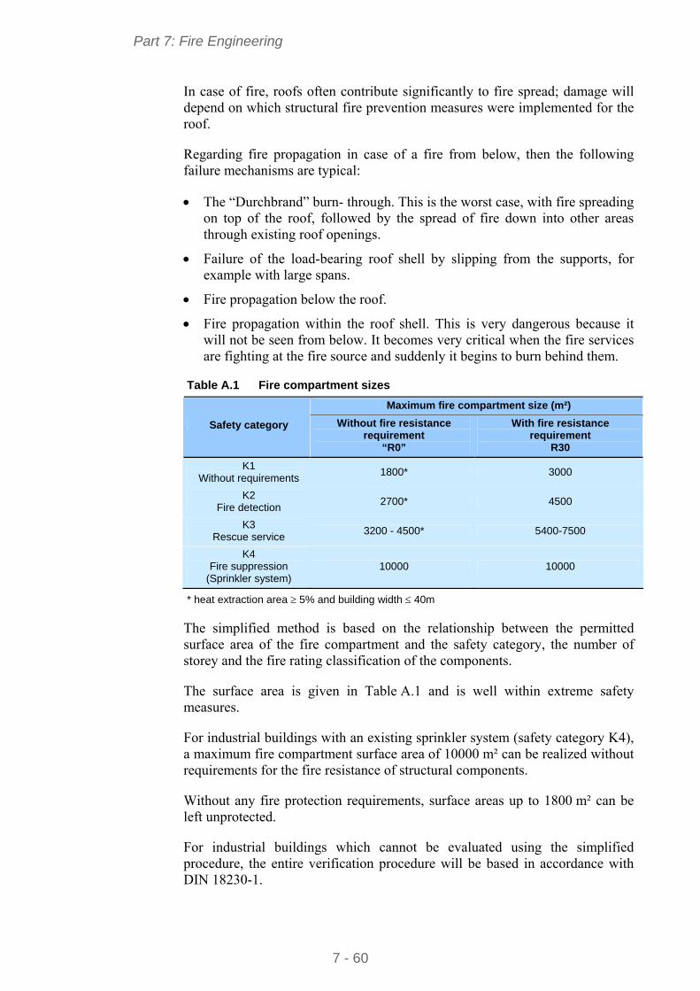
Part 7: Fire Engineering
7 - 60
In case of fire, roofs often contribute significantly to fire spread; damage will depend on which structural fire prevention measures were implemented for the roof.
Regarding fire propagation in case of a fire from below, then the following failure mechanisms are typical:
The “Durchbrand” burn- through. This is the worst case, with fire spreading on top of the roof, followed by the spread of fire down into other areas through existing roof openings.
Failure of the load-bearing roof shell by slipping from the supports, for example with large spans.
Fire propagation below the roof.
Fire propagation within the roof shell. This is very dangerous because it will not be seen from below. It becomes very critical when the fire services are fighting at the fire source and suddenly it begins to burn behind them.
Table A.1 Fire compartment sizes
Maximum fire compartment size (m²)
Safety category Without fire resistance requirement
“R0”
With fire resistance requirement
R30
K1 Without requirements
1800* 3000
K2 Fire detection
2700* 4500
K3 Rescue service
3200 - 4500* 5400-7500
K4 Fire suppression
(Sprinkler system) 10000 10000
* heat extraction area 5% and building width 40m
The simplified method is based on the relationship between the permitted surface area of the fire compartment and the safety category, the number of storey and the fire rating classification of the components.
The surface area is given in Table A.1 and is well within extreme safety measures.
For industrial buildings with an existing sprinkler system (safety category K4), a maximum fire compartment surface area of 10000 m² can be realized without requirements for the fire resistance of structural components.
Without any fire protection requirements, surface areas up to 1800 m² can be left unprotected.
For industrial buildings which cannot be evaluated using the simplified procedure, the entire verification procedure will be based in accordance with DIN 18230-1.
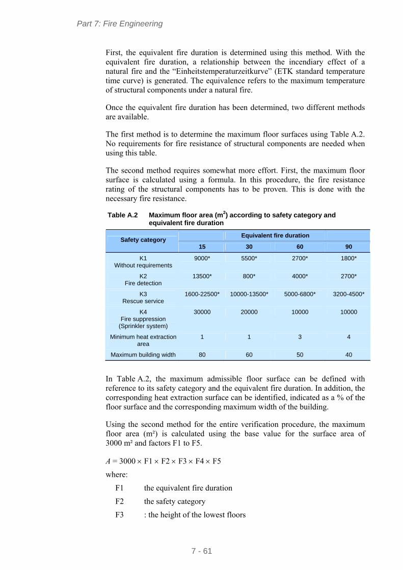
Part 7: Fire Engineering
7 - 61
First, the equivalent fire duration is determined using this method. With the equivalent fire duration, a relationship between the incendiary effect of a natural fire and the “Einheitstemperaturzeitkurve” (ETK standard temperature time curve) is generated. The equivalence refers to the maximum temperature of structural components under a natural fire.
Once the equivalent fire duration has been determined, two different methods are available.
The first method is to determine the maximum floor surfaces using Table A.2. No requirements for fire resistance of structural components are needed when using this table.
The second method requires somewhat more effort. First, the maximum floor surface is calculated using a formula. In this procedure, the fire resistance rating of the structural components has to be proven. This is done with the necessary fire resistance.
Table A.2 Maximum floor area (m2) according to safety category and equivalent fire duration
Equivalent fire duration Safety category
15 30 60 90
K1 Without requirements
9000* 5500* 2700* 1800*
K2 Fire detection
13500* 800* 4000* 2700*
K3 Rescue service
1600-22500* 10000-13500* 5000-6800* 3200-4500*
K4 Fire suppression
(Sprinkler system)
30000 20000 10000 10000
Minimum heat extraction area
1 1 3 4
Maximum building width 80 60 50 40
In Table A.2, the maximum admissible floor surface can be defined with reference to its safety category and the equivalent fire duration. In addition, the corresponding heat extraction surface can be identified, indicated as a % of the floor surface and the corresponding maximum width of the building.
Using the second method for the entire verification procedure, the maximum floor area (m²) is calculated using the base value for the surface area of 3000 m² and factors F1 to F5.
A = 3000 F1 F2 F3 F4 F5
where:
F1 the equivalent fire duration
F2 the safety category
F3 : the height of the lowest floors
Part 7: Fire Engineering
7 - 62
F4 : the number of storey
F5 : the type of floor openings
The sum of the total surface area shall not exceed 60000 m².
According to the Table A.2, when the simplified procedure is used for structural components without requirements, the result is a maximum possible surface area of 10 000 m².
When using the full verification procedure according to this table, a maximum surface of 30000 m² is possible. When using the full verification procedure in addition to the fire resistance calculation, then a 60000 m² surface area is possible.
Under very special conditions, even larger surfaces, up to 120000 m² can be achieved.
Example:
The procedure and possibilities associated with MIndBauRl can best be shown and explained by an example:
Building parameters
Length: 100 m
Width: 50 m
Average height: 6 m
Size: 5000 m²
Number of storey: 1
Openings in the roof: 135 m²
Doors, windows: 132 m²
Fire load: qR = 126 kWh/m²
Automatic fire alarm systems: Safety category K2
No internal fire walls
The first possibility is the simplified method according to Table A.1. The industrial building must be equipped with an automatic sprinkler in order to meet the above conditions.
In order to apply fully the full verification method, the equivalent fire duration must first be determined. In this case, the heat extraction factor w is needed. The heat extraction factor is determined by taking into account the related opening surfaces. The related opening surfaces are auxiliary values. This is simply a question of dividing the roof openings by the ground surface and then the wall openings by the ground surface.
Determination of the related horizontal opening surface ah:
ah = Ah / A = 135 m² / 5000 m² = 0,027
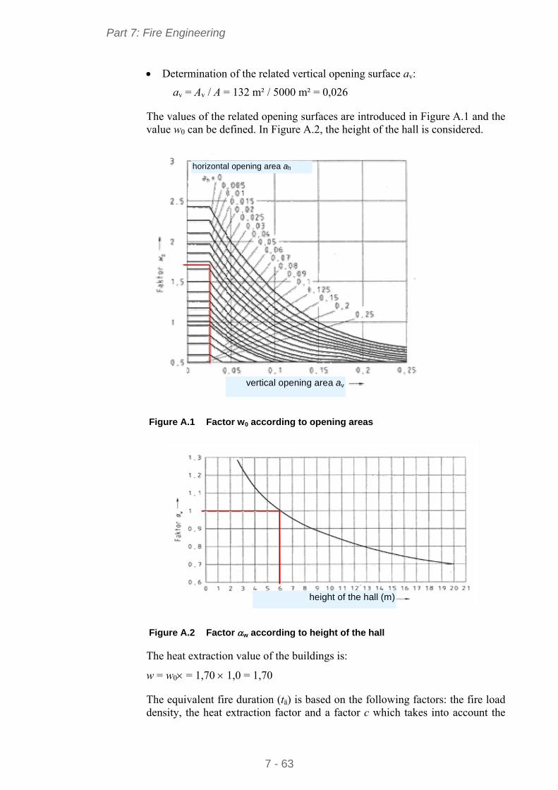
Part 7: Fire Engineering
7 - 63
Determination of the related vertical opening surface av:
av = Av / A = 132 m² / 5000 m² = 0,026
The values of the related opening surfaces are introduced in Figure A.1 and the value w0 can be defined. In Figure A.2, the height of the hall is considered.
vertical opening area av
horizontal opening area ah
Figure A.1 Factor w0 according to opening areas
height of the hall (m)
Figure A.2 Factor w according to height of the hall
The heat extraction value of the buildings is:
w = w0 = 1,70 1,0 = 1,70
The equivalent fire duration (tä) is based on the following factors: the fire load density, the heat extraction factor and a factor c which takes into account the
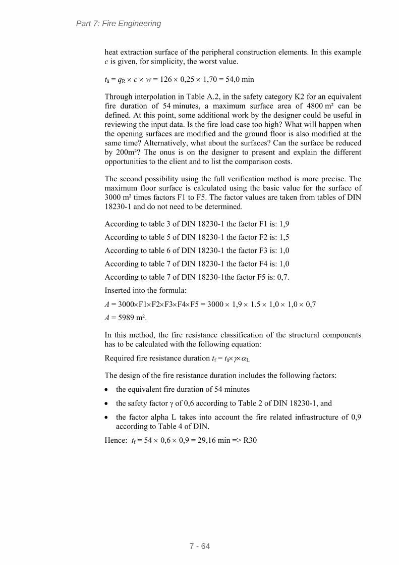
Part 7: Fire Engineering
7 - 64
heat extraction surface of the peripheral construction elements. In this example c is given, for simplicity, the worst value.
tä = qR c w = 126 0,25 1,70 = 54,0 min
Through interpolation in Table A.2, in the safety category K2 for an equivalent fire duration of 54 minutes, a maximum surface area of 4800 m² can be defined. At this point, some additional work by the designer could be useful in reviewing the input data. Is the fire load case too high? What will happen when the opening surfaces are modified and the ground floor is also modified at the same time? Alternatively, what about the surfaces? Can the surface be reduced by 200m²? The onus is on the designer to present and explain the different opportunities to the client and to list the comparison costs.
The second possibility using the full verification method is more precise. The maximum floor surface is calculated using the basic value for the surface of 3000 m² times factors F1 to F5. The factor values are taken from tables of DIN 18230-1 and do not need to be determined.
According to table 3 of DIN 18230-1 the factor F1 is: 1,9
According to table 5 of DIN 18230-1 the factor F2 is: 1,5
According to table 6 of DIN 18230-1 the factor F3 is: 1,0
According to table 7 of DIN 18230-1 the factor F4 is: 1,0
According to table 7 of DIN 18230-1the factor F5 is: 0,7.
Inserted into the formula:
A = 3000F1F2F3F4F5 = 3000 1,9 1.5 1,0 1,0 0,7
A = 5989 m².
In this method, the fire resistance classification of the structural components has to be calculated with the following equation:
Required fire resistance duration tf = täL
The design of the fire resistance duration includes the following factors:
the equivalent fire duration of 54 minutes
the safety factor of 0,6 according to Table 2 of DIN 18230-1, and
the factor alpha L takes into account the fire related infrastructure of 0,9 according to Table 4 of DIN.
Hence: tf = 54 0,6 0,9 = 29,16 min => R30
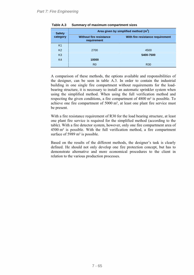
Part 7: Fire Engineering
7 - 65
Table A.3 Summary of maximum compartment sizes
Area given by simplified method (m2) Safety
category Without fire resistance requirement
With fire resistance requirement
K1
K2 2700 4500
K3 5400-7500
K4 10000
R0 R30
A comparison of these methods, the options available and responsibilities of the designer, can be seen in table A.3. In order to contain the industrial building in one single fire compartment without requirements for the load-bearing structure, it is necessary to install an automatic sprinkler system when using the simplified method. When using the full verification method and respecting the given conditions, a fire compartment of 4800 m² is possible. To achieve one fire compartment of 5000 m², at least one plant fire service must be present.
With a fire resistance requirement of R30 for the load bearing structure, at least one plant fire service is required for the simplified method (according to the table). With a fire detector system, however, only one fire compartment area of 4500 m² is possible. With the full verification method, a fire compartment surface of 5989 m² is possible.
Based on the results of the different methods, the designer’s task is clearly defined. He should not only develop one fire protection concept, but has to demonstrate alternative and more economical procedures to the client in relation to the various production processes.