Embed Size (px)
Citation preview

Steel Design Guide Series
Steel and Composite Beams with
Web Openings

Steel Design Guide Series
Steel andComposite Beamswith Web Openings
Design of Steel and Composite Beams with Web OpeningsDavid DarwinProfessor of Civil EngineeringUniversity of KansasLawrence, Kansas
A M E R I C A N I N S T I T U T E O F S T E E L C O N S T R U C T I O N
© 2003 by American Institute of Steel Construction, Inc. All rights reserved.This publication or any part thereof must not be reproduced in any form without permission of the publisher.
Copyright 1990
by
American Institute of Steel Construction, Inc.
All rights reserved. This book or any part thereofmust not be reproduced in any form without the
written permission of the publisher.
The information presented in this publication has been prepared in accordance with rec-ognized engineering principles and is for general information only. While it is believedto be accurate, this information should not be used or relied upon for any specific appli-cation without competent professional examination and verification of its accuracy,suitablility, and applicability by a licensed professional engineer, designer, or architect.The publication of the material contained herein is not intended as a representationor warranty on the part of the American Institute of Steel Construction or of any otherperson named herein, that this information is suitable for any general or particular useor of freedom from infringement of any patent or patents. Anyone making use of thisinformation assumes all liability arising from such use.
Caution must be exercised when relying upon other specifications and codes developedby other bodies and incorporated by reference herein since such material may be mod-ified or amended from time to time subsequent to the printing of this edition. TheInstitute bears no responsibility for such material other than to refer to it and incorporateit by reference at the time of the initial publication of this edition.
Printed in the United States of America
Second Printing: September 1991
Third Printing: October 2003
© 2003 by American Institute of Steel Construction, Inc. All rights reserved.This publication or any part thereof must not be reproduced in any form without permission of the publisher.
TABLE OF CONTENTS
INTRODUCTION . . . . . . . . . . . . . . . . . . . . . . . . . . . . . 1
DEFINITIONS AND NOTATION . . . . . . . . . . . . . . . 32.1 Definitions . . . . . . . . . . . . . . . . . . . . . . . . . . . . . . . 32.2 N o t a t i o n . . . . . . . . . . . . . . . . . . . . . . . . . . . . . . . . . 3
DESIGN OF MEMBERS WITH WEB OPENINGS 73.1 G e n e r a l . . . . . . . . . . . . . . . . . . . . . . . . . . . . . . . . . . 73.2 Load and Resistance Factors . . . . . . . . . . . . . . . . 73.3 Overview of Design Procedures . . . . . . . . . . . . . 73.4 Moment-Shear Interaction . . . . . . . . . . . . . . . . . . 83.5 Equations for Maximum Moment Capacity,
Mm . . . . . . . . . . . . . . . . . . . . . . . . . . . . . . . . . . . . . 83.6 Equations for Maximum Shear Capacity, Vm . . . 103.7 Guidelines for Proportioning and Detailing
Beams with Web O p e n i n g s . . . . . . . . . . . . . . . . . . 123.8 Allowable Stress Design . . . . . . . . . . . . . . . . . . . . 16
DESIGN SUMMARIES AND EXAMPLEP R O B L E M S . . . . . . . . . . . . . . . . . . . . . . . . . . . . . . . . . 17
4.1 General.. . . . . . . . . . . . . . . . . . . . . . . . . . . . . . . . . 174.2 Example 1: Steel Beam with Unreinforced
Opening . . . . . . . . . . . . . . . . . . . . . . . . . . . . . . . . . 224.3 Example 1A: Steel Beam with Unreinforced
Opening—ASD Approach . . . . . . . . . . . . . . . . . . 234.4 Example 2: Steel Beam with Reinforced
O p e n i n g . . . . . . . . . . . . . . . . . . . . . . . . . . . . . . . . . 24
4.5 Example 3: Composite Beam withUnreinforced Opening . . . . . . . . . . . . . . . . . . . . . 27
4.6 Example 4: Composite Girder withUnreinforced and Reinforced Openings . . . . . . . . 30
BACKGROUND AND COMMENTARY . . . . . . . . . . 375.1 G e n e r a l . . . . . . . . . . . . . . . . . . . . . . . . . . . . . . . . . . 375.2 Behavior of Members with Web Openings . . . . . 375.3 Design of Members with Web Openings . . . . . . 405.4 Moment-Shear Interaction . . . . . . . . . . . . . . . . . . 415.5 Equations for Maximum Moment Capacity . . . . 425.6 Equations for Maximum Shear Capacity . . . . . . 445.7 Guidelines for Proportioning and Detailing
Beams with Web Openings . . . . . . . . . . . . . . . . . 485.8 Allowable Stress Design . . . . . . . . . . . . . . . . . . . . 50
D E F L E C T I O N S . . . . . . . . . . . . . . . . . . . . . . . . . . . . . . 516.1 General. . . . . . . . . . . . . . . . . . . . . . . . . . . . . . . . . . 516.2 Design Approaches . . . . . . . . . . . . . . . . . . . . . . . . 516.3 Approximate Procedure . . . . . . . . . . . . . . . . . . . . . 516.4 Improved Procedure . . . . . . . . . . . . . . . . . . . . . . . 526.5 Matrix A n a l y s i s . . . . . . . . . . . . . . . . . . . . . . . . . . . 53
R E F E R E N C E S . . . . . . . . . . . . . . . . . . . . . . . . . . . . . . . . 55
ADDITIONAL BIBLIOGRAPHY . . . . . . . . . . . . . . . 57
APPENDIX A . . . . . . . . . . . . . . . . . . . . . . . . . . . . . . . . 59
INDEX . . . . . . . . . . . . . . . . . . . . . . . . . . . . . . . . . . . . . . 63
© 2003 by American Institute of Steel Construction, Inc. All rights reserved.This publication or any part thereof must not be reproduced in any form without permission of the publisher.
PREFACE
This booklet was prepared under the direction of the Com-mittee on Research of the American Institute of Steel Con-struction, Inc. as part of a series of publications on specialtopics related to fabricated structural steel. Its purpose is toserve as a supplemental reference to the AISC Manual ofSteel Construction to assist practicing engineers engaged inbuilding design.
The design guidelines suggested by the author that are out-side the scope of the AISC Specifications or Code do notrepresent an official position of the Institute and are not in-tended to exclude other design methods and procedures. Itis recognized that the design of structures is within the scopeof expertise of a competent licensed structural engineer, ar-chitect or other licensed professional for the application ofprinciples to a particular structure.
The sponsorship of this publication by the American Ironand Steel Institute is gratefully acknowledged.
The information presented in this publication has been prepared in accordance with recognized engineer-ing principles and is for general information only. While it is believed to be accurate, this information shouldnot be used or relied upon for any specific application without competent professional examination and verifi-cation of its accuracy, suitability, and applicability by a licensed professional engineer, designer or archi-tect. The publication of the material contained herein is not intended as a representation or warranty onthe part of the American Institute of Steel Construction, Inc. or the American Iron and Steel Institute, orof any other person named herein, that this information is suitable for any general or particular use or offreedom infringement of any patent or patents. Anyone making use of this information assumes all liabilityarising from such use.
© 2003 by American Institute of Steel Construction, Inc. All rights reserved.This publication or any part thereof must not be reproduced in any form without permission of the publisher.
Chapter 1INTRODUCTION
Height limitations are often imposed on multistory buildingsbased on zoning regulations, economic requirements and es-thetic considerations, including the need to match the floorheights of existing buildings. The ability to meet these restric-tions is an important consideration in the selection of a fram-ing system and is especially important when the framing sys-tem is structural steel. Web openings can be used to passutilities through beams and, thus, help minimize story height.A decrease in building height reduces both the exterior sur-face and the interior volume of a building, which lowers oper-ational and maintenance costs, as well as construction costs.On the negative side, web openings can significantly reducethe shear and bending capacity of steel or composite beams.
Web openings have been used for many years in structuralsteel beams, predating the development of straightforwarddesign procedures, because of necessity and/or economic ad-vantage. Openings were often reinforced, and compositebeams were often treated as noncomposite members at webopenings. Reinforcement schemes included the use of bothhorizontal and vertical bars, or bars completely around theperiphery of the opening. As design procedures were devel-oped, unreinforced and reinforced openings were often ap-proached as distinct problems, as were composite and non-composite members.
In recent years, a great deal of progress has been madein the design of both steel and composite beams with web
openings. Much of the work is summarized in state-of-the-art reports (Darwin 1985, 1988 & Redwood 1983). Amongthe benefits of this progress has been the realization that thebehavior of steel and composite beams is quite similar atweb openings. It has also become clear that a single designapproach can be used for both unreinforced and reinforcedopenings. If reinforcement is needed, horizontal bars aboveand below the opening are fully effective. Vertical bars orbars around the opening periphery are neither needed norcost effective.
This guide presents a unified approach to the design ofstructural steel members with web openings. The approachis based on strength criteria rather than allowable stresses,because at working loads, locally high stresses around webopenings have little connection with a member's deflectionor strength.
The procedures presented in the following chapters are for-mulated to provide safe, economical designs in terms of boththe completed structure and the designer's time. The designexpressions are applicable to members with individual open-ings or multiple openings spaced far enough apart so thatthe openings do not interact. Castellated beams are not in-cluded. For practical reasons, opening depth is limited to70 percent of member depth. Steel yield strength is limitedto 65 ksi and sections must meet the AISC requirements forcompact sections (AISC 1986).
1
© 2003 by American Institute of Steel Construction, Inc. All rights reserved.This publication or any part thereof must not be reproduced in any form without permission of the publisher.
Chapter 2
DEFINITIONS AND NOTATION
2.1 DEFINITIONS
The following terms apply to members with web openings.bottom tee—region of a beam below an opening.bridging—separation of the concrete slab from the steel sec-
tion in composite beams. The separation occurs over anopening between the low moment end of the opening anda point outside the opening past the high moment end ofthe opening.
high moment end—the edge of an opening subjected to thegreater primary bending moment. The secondary and pri-mary bending moments act in the same direction.
low moment end—the edge of an opening subjected to thelower primary bending moment. The secondary and pri-mary bending moments act in opposite directions.
opening parameter—quantity used to limit opening size andaspect ratio.
plastic neutral axis—position in steel section, or top or bot-tom tees, at which the stress changes abruptly from ten-sion to compression.
primary bending moment—bending moment at any pointin a beam caused by external loading.
reinforcement—longitudinal steel bars welded above and be-low an opening to increase section capacity.
reinforcement, slab—reinforcing steel within a concrete slab.secondary bending moment—bending moment within a tee
that is induced by the shear carried by the tee.tee—region of a beam above or below an opening.top tee—region of a beam above an opening.unperforated member—section without an opening. Refers
to properties of the member at the position of the opening.
Gross transformed area of a teeArea of flangeCross-sectional area of reinforcement alongtop or bottom edge of openingCross-sectional area of steel in unperforatedmemberCross-sectional area of shear studNet area of steel section with opening andreinforcementNet steel area of top teeArea of a steel teeEffective concrete shear area =Effective shear area of a steel teeDiameter of circular opening
Modulus of elasticity of steelModulus of elasticity of concreteHorizontal forces at ends of a beam elementYield strength of steelReduced axial yield strength of steel; seeEqs. 5-19 and 5-20Vertical forces at ends of a beam elementYield strength of opening reinforcementShear modulus =Moment of inertia of a steel tee, withsubscript b or tMoment of inertia of bottom steel teeMoment of inertia of unperforated steelbeam or effective moment of inertia ofunperforated composite beamMoment of inertia of perforated beamMoment of inertia of teeMoment inertia of top steel teeTorsional constantShape factor for shearElements of beam stiffness matrix, i, j = 1, 6Stiffness matrix of a beam elementLength of a beamUnbraced length of compression flangeBending moment at center line of openingSecondary bending moment at high and lowmoment ends of bottom tee, respectively.Maximum nominal bending capacity at thelocation of an openingNominal bending capacityPlastic bending capacity of an unperforatedsteel beamPlastic bending capacity of an unperforatedcomposite beamSecondary bending moment at high and lowmoment ends of top tee, respectivelyFactored bending momentMoments at ends of a beam elementNumber of shear connectors between thehigh moment end of an opening and thesupportNumber of shear connectors over anopeningAxial force in top or bottom teeForce vector for a beam elementAxial force in bottom teeAxial force in concrete for a section underpure bending
2.2 NOTATION
3
© 2003 by American Institute of Steel Construction, Inc. All rights reserved.This publication or any part thereof must not be reproduced in any form without permission of the publisher.
Minimum value of for which Eq. 3-10 isaccurate =Axial force in concrete at high and lowmoment ends of opening, respectively, for asection at maximum shear capacityPlastic neutral axisAxial force in opening reinforcementAxial force in top teeIndividual shear connector capacity, includ-ing reduction factor for ribbed slabsRatio of factored load to design capacity atan opening =
Strength reduction factor for shear studs inribbed slabsRequired strength of a weldClear space between openingsTensile force in net steel sectionDisplacement vector for a beam elementShear at openingShear in bottom teeCalculated shear carried by concrete slab =
which-ever is lessMaximum nominal shear capacity at thelocation of an openingMaximum nominal shear capacity of bottomand top tees, respectivelyPure shear capacity of top teeNominal shear capacityPlastic shear capacity of top or bottom teePlastic shear capacity of unperforated beamPlastic shear capacity of bottom and toptees, respectivelyShear in top teeFactored shearPlastic section modulusLength of openingDepth of concrete compressive blockProjecting width of flange or reinforcementEffective width of concrete slabSum of minimum rib widths for ribs that liewithin for composite beams with longitu-dinal ribs in slabWidth of flangeDepth of steel sectionDistance from top of steel section to cen-troid of concrete force at high and lowmoment ends of opening, respectively.Distance from outside edge of flange to cen-troid of opening reinforcement; may havedifferent values in top and bottom teesEccentricity of opening; always positive for steelsections; positive up for composite sections
Compressive (cylinder) strength of concreteDepth of openingDistance from center of gravity of unper-forated beam to center of gravity of a teesection, bottom tee, and top tee, respectively.Length of extension of reinforcement beyondedge of openingDistance from high moment end of openingto adjacent supportDistance from low moment end of openingto adjacent supportDistance from support to point at whichdeflection is calculatedDistance from high moment end of openingto point at which deflection is calculated
Opening parameter =
Ratio of midspan deflection of a beam withan opening to midspan deflection of a beamwithout an openingDepth of a tee, bottom tee and top tee,respectivelyEffective depth of a tee, bottom tee and toptee, respectively, to account for movementof PNA when an opening is reinforced; usedonly for calculation ofThickness of flange or reinforcementEffective thickness of concrete slabThickness of flangeTotal thickness of concrete slabThickness of concrete slab above the ribThickness of webHorizontal displacements at ends of a beamelementVertical displacements at ends of a beamelementUniform loadFactored uniform loadDistance from top of flange to plastic neu-tral axis in flange or web of a compositebeamDistance between points about which sec-ondary bending moments are calculatedVariables used to calculateRatio of maximum nominal shear capacityto plastic shear capacity of a tee,
Term in stiffness matrix for equivalent beamelement at web opening; see Eq. 6-12Net reduction in area of steel section due topresence of an opening and reinforcement =
4
© 2003 by American Institute of Steel Construction, Inc. All rights reserved.This publication or any part thereof must not be reproduced in any form without permission of the publisher.
Dimensionless ratio relating the secondarybending moment contributions of concreteand opening reinforcement to the product ofthe plastic shear capacity of a tee and thedepth of the tee
Ratio of length to depth or length to effec-tive depth for a tee, bottom tee or top tee,respectively =Poisson's ratioAverage shear stressResistance factor
Bottom teeMaximum or meanNominalTop teeFactored
Maximum deflection due to bending of abeam without an openingMaximum deflection of a beam with anopening due to bending and shearDeflection through an openingBending deflection through an openingShear deflection through an openingComponents of deflection caused by pres-ence of an opening at a point between highmoment end of opening and supportMaximum deflection due to shear of a beamwithout an openingRotations of a beam at supports due to pres-ence of an opening = see Eq.6-12Rotations used to calculate beam deflectionsdue to presence of an opening; see Eq. 6-3Rotations at ends of a beam elementConstant used in linear approximation ofvon Mises yield criterion; recommendedvalue
5
© 2003 by American Institute of Steel Construction, Inc. All rights reserved.This publication or any part thereof must not be reproduced in any form without permission of the publisher.
Chapter 3
DESIGN OF MEMBERS WITH WEB OPENINGS
3.1 GENERAL
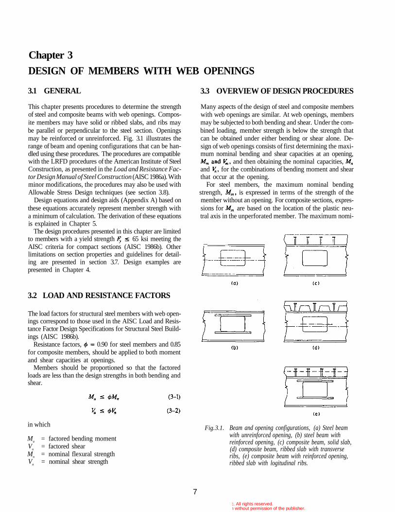
This chapter presents procedures to determine the strengthof steel and composite beams with web openings. Compos-ite members may have solid or ribbed slabs, and ribs maybe parallel or perpendicular to the steel section. Openingsmay be reinforced or unreinforced. Fig. 3.1 illustrates therange of beam and opening configurations that can be han-dled using these procedures. The procedures are compatiblewith the LRFD procedures of the American Institute of SteelConstruction, as presented in the Load and Resistance Fac-tor Design Manual of Steel Construction (AISC 1986a). Withminor modifications, the procedures may also be used withAllowable Stress Design techniques (see section 3.8).
Design equations and design aids (Appendix A) based onthese equations accurately represent member strength witha minimum of calculation. The derivation of these equationsis explained in Chapter 5.
The design procedures presented in this chapter are limitedto members with a yield strength 65 ksi meeting theAISC criteria for compact sections (AISC 1986b). Otherlimitations on section properties and guidelines for detail-ing are presented in section 3.7. Design examples arepresented in Chapter 4.
3.2 LOAD AND RESISTANCE FACTORS
The load factors for structural steel members with web open-ings correspond to those used in the AISC Load and Resis-tance Factor Design Specifications for Structural Steel Build-ings (AISC 1986b).
Resistance factors, 0.90 for steel members and 0.85for composite members, should be applied to both momentand shear capacities at openings.
Members should be proportioned so that the factoredloads are less than the design strengths in both bending andshear.
3.3 OVERVIEW OF DESIGN PROCEDURES
Many aspects of the design of steel and composite memberswith web openings are similar. At web openings, membersmay be subjected to both bending and shear. Under the com-bined loading, member strength is below the strength thatcan be obtained under either bending or shear alone. De-sign of web openings consists of first determining the maxi-mum nominal bending and shear capacities at an opening,
and then obtaining the nominal capacities,and for the combinations of bending moment and shearthat occur at the opening.
For steel members, the maximum nominal bendingstrength, is expressed in terms of the strength of themember without an opening. For composite sections, expres-sions for are based on the location of the plastic neu-tral axis in the unperforated member. The maximum nomi-
Fig. 3.1. Beam and opening configurations, (a) Steel beamwith unreinforced opening, (b) steel beam withreinforced opening, (c) composite beam, solid slab,(d) composite beam, ribbed slab with transverseribs, (e) composite beam with reinforced opening,ribbed slab with logitudinal ribs.
in which
Mu = factored bending momentVu = factored shearMn = nominal flexural strengthVn = nominal shear strength
7© 2003 by American Institute of Steel Construction, Inc. All rights reserved.
This publication or any part thereof must not be reproduced in any form without permission of the publisher.
nal shear capacity, is expressed as the sum of the shearcapacities, for the regions above and below theopening (the top and bottom tees).
The design expressions for composite beams apply to open-ings located in positive moment regions. The expressions forsteel beams should be used for openings placed in negativemoment regions of composite members.
The next three sections present the moment-shear inter-action curve and expressions for used to designmembers with web openings. Guidelines for member propor-tions follow the presentation of the design equations.
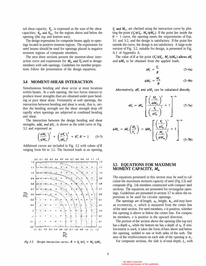
are checked using the interaction curve by plot-ting the point If the point lies inside theR = 1 curve, the opening meets the requirements of Eqs.3-1 and 3-2, and the design is satisfactory. If the point liesoutside the curve, the design is not satisfactory. A large-scaleversion of Fig. 3.2, suitable for design, is presented in Fig.A.1 of Appendix A.
The value of R at the pointand to be obtained from the applied loads.
3.4 MOMENT-SHEAR INTERACTION
Simultaneous bending and shear occur at most locationswithin beams. At a web opening, the two forces interact toproduce lower strengths than are obtained under pure bend-ing or pure shear alone. Fortunately at web openings, theinteraction between bending and shear is weak, that is, nei-ther the bending strength nor the shear strength drop offrapidly when openings are subjected to combined bendingand shear.
The interaction between the design bending and shearstrengths, is shown as the solid curve in Fig.3.2 and expressed as
Additional curves are included in Fig. 3.2 with values of Rranging from 0.6 to 1.2. The factored loads at an opening,
3.5 EQUATIONS FOR MAXIMUMMOMENT CAPACITY,
The equations presented in this section may be used to cal-culate the maximum moment capacity of steel (Fig 3.3) andcomposite (Fig. 3.4) members constructed with compact steelsections. The equations are presented for rectangular open-ings. Guidelines are presented in section 3.7 to allow the ex-pressions to be used for circular openings.
The openings are of length, height, and may havean eccentricity, e, which is measured from the center lineof the steel section. For steel members, e is positive, whetherthe opening is above or below the center line. For compos-ite members, e is positive in the upward direction.
The portion of the section above the opening (the top tee)has a depth while the bottom tee has a depth of If rein-forcement is used, it takes the form of bars above and belowthe opening, welded to one or both sides of the web. Thearea of the reinforcement on each side of the opening is
For composite sections, the slab is of total depth, with
8
© 2003 by American Institute of Steel Construction, Inc. All rights reserved.This publication or any part thereof must not be reproduced in any form without permission of the publisher.
(b)
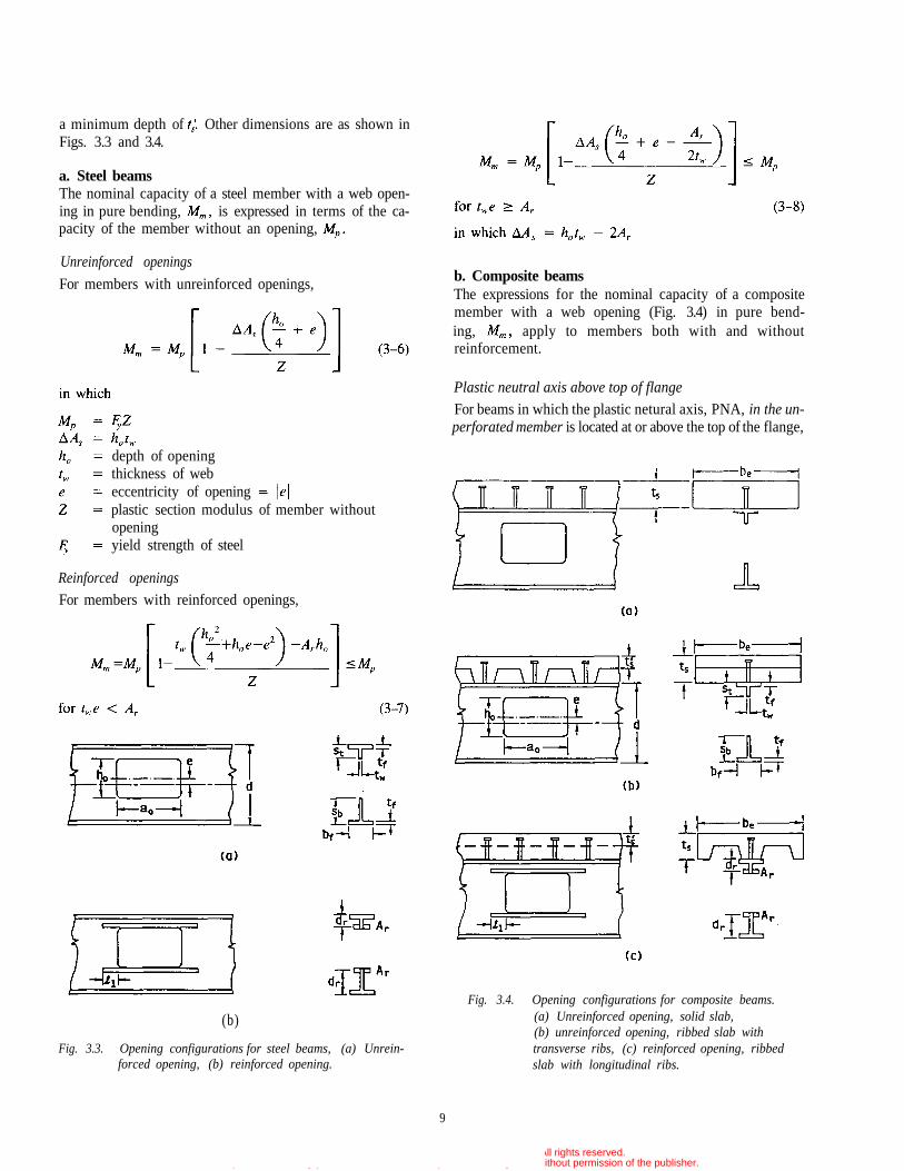
Fig. 3.3. Opening configurations for steel beams, (a) Unrein-forced opening, (b) reinforced opening.
b. Composite beamsThe expressions for the nominal capacity of a compositemember with a web opening (Fig. 3.4) in pure bend-ing, apply to members both with and withoutreinforcement.
Plastic neutral axis above top of flange
For beams in which the plastic netural axis, PNA, in the un-perforated member is located at or above the top of the flange,
Fig. 3.4. Opening configurations for composite beams.(a) Unreinforced opening, solid slab,(b) unreinforced opening, ribbed slab withtransverse ribs, (c) reinforced opening, ribbedslab with longitudinal ribs.
a minimum depth of Other dimensions are as shown inFigs. 3.3 and 3.4.
a. Steel beamsThe nominal capacity of a steel member with a web open-ing in pure bending, is expressed in terms of the ca-pacity of the member without an opening,
Unreinforced openings
For members with unreinforced openings,
Reinforced openings
For members with reinforced openings,
depth of openingthickness of webeccentricity of openingplastic section modulus of member withoutopeningyield strength of steel
9
© 2003 by American Institute of Steel Construction, Inc. All rights reserved.This publication or any part thereof must not be reproduced in any form without permission of the publisher.
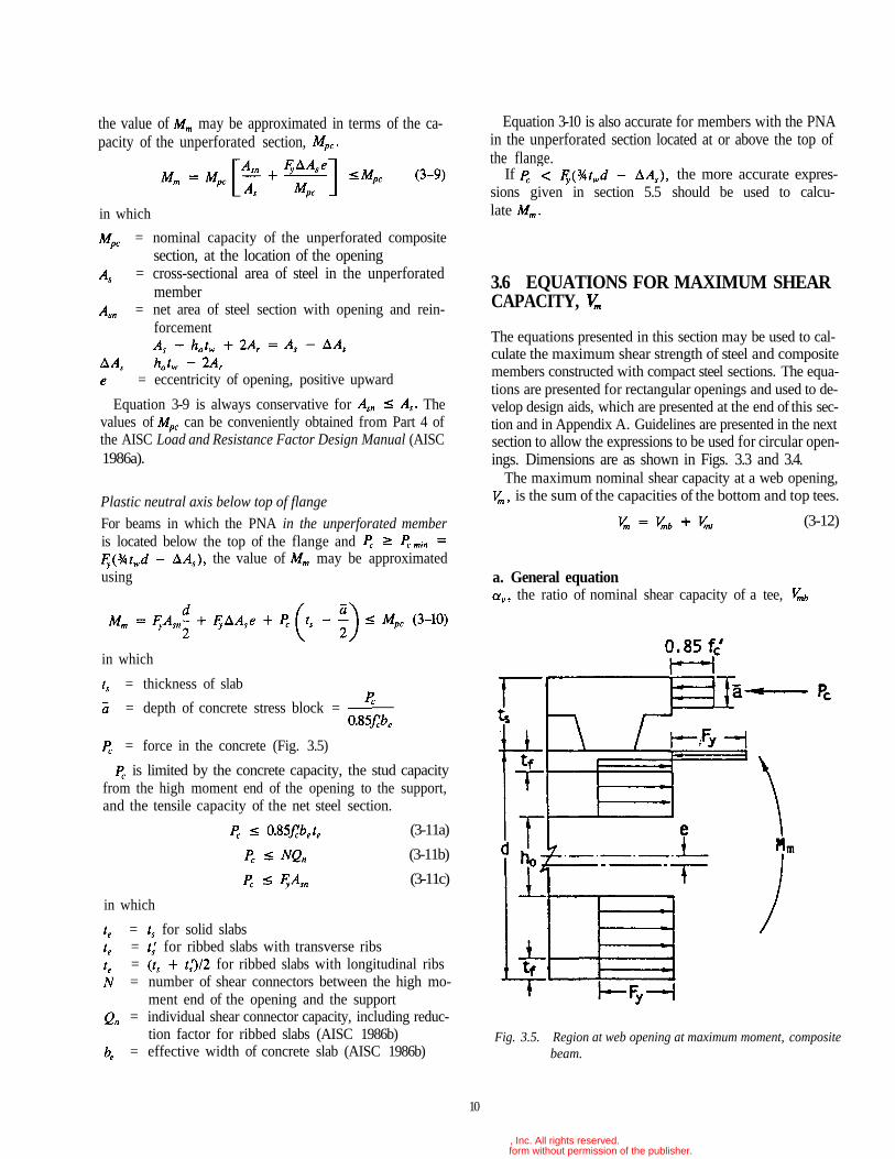
Fig. 3.5. Region at web opening at maximum moment, compositebeam.
10
the value of may be approximated in terms of the ca-pacity of the unperforated section,
in which
= nominal capacity of the unperforated compositesection, at the location of the opening
= cross-sectional area of steel in the unperforatedmember
= net area of steel section with opening and rein-forcement
= eccentricity of opening, positive upward
Equation 3-9 is always conservative for Thevalues of can be conveniently obtained from Part 4 ofthe AISC Load and Resistance Factor Design Manual (AISC1986a).
Plastic neutral axis below top of flangeFor beams in which the PNA in the unperforated memberis located below the top of the flange and
the value of may be approximatedusing
in which
= thickness of slab
= depth of concrete stress block =
= force in the concrete (Fig. 3.5)
is limited by the concrete capacity, the stud capacityfrom the high moment end of the opening to the support,and the tensile capacity of the net steel section.
(3-11a)
(3-11b)
(3-11c)
in which
= for solid slabs= for ribbed slabs with transverse ribs= for ribbed slabs with longitudinal ribs= number of shear connectors between the high mo-
ment end of the opening and the support= individual shear connector capacity, including reduc-
tion factor for ribbed slabs (AISC 1986b)= effective width of concrete slab (AISC 1986b)
Equation 3-10 is also accurate for members with the PNAin the unperforated section located at or above the top ofthe flange.
If the more accurate expres-sions given in section 5.5 should be used to calcu-late
3.6 EQUATIONS FOR MAXIMUM SHEARCAPACITY,
The equations presented in this section may be used to cal-culate the maximum shear strength of steel and compositemembers constructed with compact steel sections. The equa-tions are presented for rectangular openings and used to de-velop design aids, which are presented at the end of this sec-tion and in Appendix A. Guidelines are presented in the nextsection to allow the expressions to be used for circular open-ings. Dimensions are as shown in Figs. 3.3 and 3.4.
The maximum nominal shear capacity at a web opening,is the sum of the capacities of the bottom and top tees.
(3-12)
a. General equationthe ratio of nominal shear capacity of a tee,
© 2003 by American Institute of Steel Construction, Inc. All rights reserved.This publication or any part thereof must not be reproduced in any form without permission of the publisher.
11
or to the plastic shear capacity of the web of the tee,is calculated as
(3-13)
in which
= aspect ratio of tee = use
when reinforcement is used
= depth of tee,
= used to calculatewhen reinforcement is used
= width of flange= length of opening
Subscripts "b" and "t" indicate the bottom and top tees,respectively.
(3-14)
in which (see Fig. 3.5)
= force in reinforcement along edge of opening
= distance from outside edge of flange to centroid ofreinforcement
and = concrete forces at high and low moment endsof opening, respectively. For top tee in com-posite sections only. See Eqs. 3-15a through3-16.
and = distances from outside edge of top flange tocentroid of concrete force at high and low mo-ment ends of opening, respectively. For top teein composite sections only. See Eqs. 3-17through 3-18b.
For reinforced openings, s should be replaced by in thecalculation of only.
For tees without concrete, . For tees with-out concrete or reinforcement, = 0. For eccentric open-ings,
Equations 3-13 and 3-14 are sufficient for all types of con-struction, with the exception of top tees in composite beamswhich are covered next.
b. Composite beamsThe following expressions apply to the top tee of compositemembers. They are used in conjunction with Eqs. 3-13 and 3-4,
the concrete force at the high moment end of theopening (Eq. 3-14, Fig. 3.6), is
(3-15a)
(3-15b)
(3-15c)
in which = net steel area of top tee
Pcl , the concrete force at the low moment end of theopening (Fig. 3.6), is
(3-16)
in which = number of shear connectors over theopening.
N in Eq. 3-15b and in Eq. 3-16 include only connec-tors completely within the defined range. For example, studson the edges of an opening are not included.
the distances from the top of the flange to thecentroid of the concrete force at the high and the low mo-ment ends of the opening, respectively, are
(3-17)
(3-18a)
for ribbed slabs (3-18b)with transverse ribs
For ribbed slabs with longitudinal ribs, is based on thecentroid of the compressive force in the concrete consider-ing all ribs that lie within the effective width (Fig. 3.4).In this case, can be conservatively obtained using Eq.3-18a, replacing the sum of the minimum ribwidths for the ribs that lie within
If the ratio of in Eq. 3-13 exceeds 1, then an al-ternate expression must be used.
(3-19)
in which for both reinforced and unreinforcedopenings.
To evaluate in Eq. 3-19, the value of in Eq. 3-15must be compared with the tensile force in the flange andreinforcement, since the web has fully yielded in shear.
(3-20)
in which
= width of flange= thickness of flange
Equation 3-20 takes the place of Eq. 3-15c.
© 2003 by American Institute of Steel Construction, Inc. All rights reserved.This publication or any part thereof must not be reproduced in any form without permission of the publisher.
If Eq. 3-20 governs instead of Eq. 3-15,and must also be recalculated using Eqs. 3-16, 3-17, 3-18,and 3-14, respectively.
Finally, must not be greater than the pure shear ca-pacity of the top tee,
(3-21)
in which are in ksi
= effective concrete shear area
c. Design aidsA design aid representing from Eq. 3-13 is presented inFigs. 3.7 and A.2 for values of ranging from 0 to 12 andvalues of ranging from 0 to 11. This design aid is applic-able to unreinforced and reinforced tees without concrete,as well as top tees in composite members, withor less than or equal to 1.
A design aid for from Eq. 3-19 for the top tee in com-posite members with 1 is presented in Figs. 3.8 andA.3. This design aid is applicable for values of from 0 to12 and values of from 0.5 to 23. If must berecalculated if Eq. 3-20 controls Pch, and a separate checkmust be made for (sh) using Eq. 3-21.
The reader will note an offset at =1 between Figs. A.2and A.3 (Figs. 3.7 and 3.8). This offset is the result of a discon-
tinuity between Eqs. 3-13 and 3-19 at If appearsto be 1 on Fig. A.2 and 1 on Fig. A.3, use = 1.
3.7 GUIDELINES FOR PROPORTIONINGAND DETAILING BEAMS WITH WEBOPENINGS
To ensure that the strength provided by a beam at a web open-ing is consistent with the design equations presented in sec-tions 3.4-3.6, a number of guidelines must be followed. Un-less otherwise stated, these guidelines apply to unreinforcedand reinforced web openings in both steel and compositebeams. All requirements of the AISC Specifications (AISC1986b) should be applied. The steel sections should meetthe AISC requirements for compact sections in both com-posite and non-composite members. 65 ksi.
a. Stability considerationsTo ensure that local instabilities do not occur, considerationmust be given to local buckling of the compression flange,web buckling, buckling of the tee-shaped compression zoneabove or below the opening, and lateral buckling of the com-pression flange.
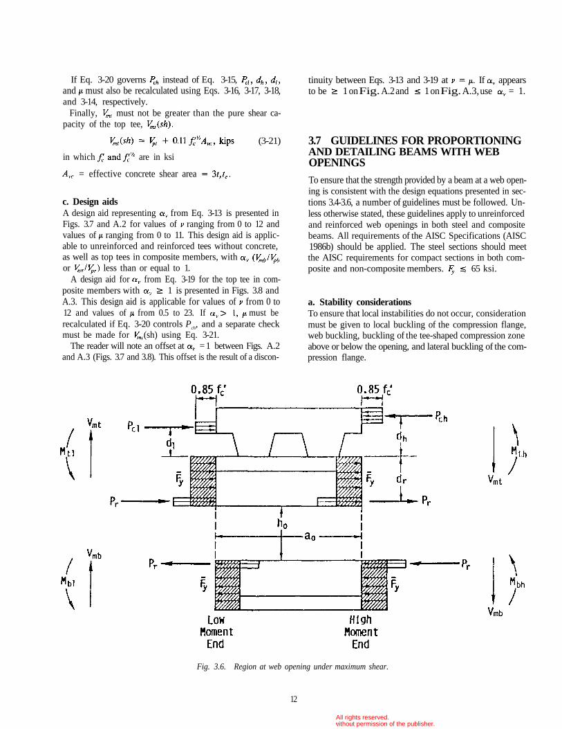
Fig. 3.6. Region at web opening under maximum shear.
12
© 2003 by American Institute of Steel Construction, Inc. All rights reserved.This publication or any part thereof must not be reproduced in any form without permission of the publisher.
13
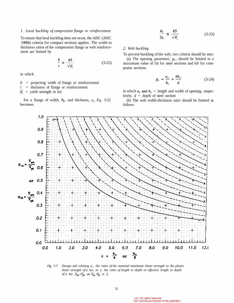
Fig. 3.7. Design aid relating av, the ratio of the nominal maximum shear strength to the plasticshear strength of a tee, to v, the ratio of length to depth or effective length to depthof a tee.
1. Local buckling of compression flange or reinforcement
To ensure that local buckling does not occur, the AISC (AISC1986b) criteria for compact sections applies. The width tothickness ratios of the compression flange or web reinforce-ment are limited by
(3-22)
in which
b = projecting width of flange or reinforcementt = thickness of flange or reinforcement
= yield strength in ksi
For a flange of width, and thickness, Eq. 3-22becomes
(3-23)
2. Web buckling
To prevent buckling of the web, two criteria should be met:(a) The opening parameter, should be limited to a
maximum value of 5.6 for steel sections and 6.0 for com-posite sections.
(3-24)
in which = length and width of opening, respec-tively, d = depth of steel section
(b) The web width-thickness ratio should be limited asfollows
© 2003 by American Institute of Steel Construction, Inc. All rights reserved.This publication or any part thereof must not be reproduced in any form without permission of the publisher.
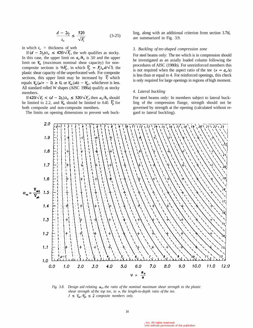
Fig. 3.8. Design aid relating the ratio of the nominal maximum shear strength to the plasticshear strength of the top tee, to the length-to-depth ratio of the tee.
composite members only.
14
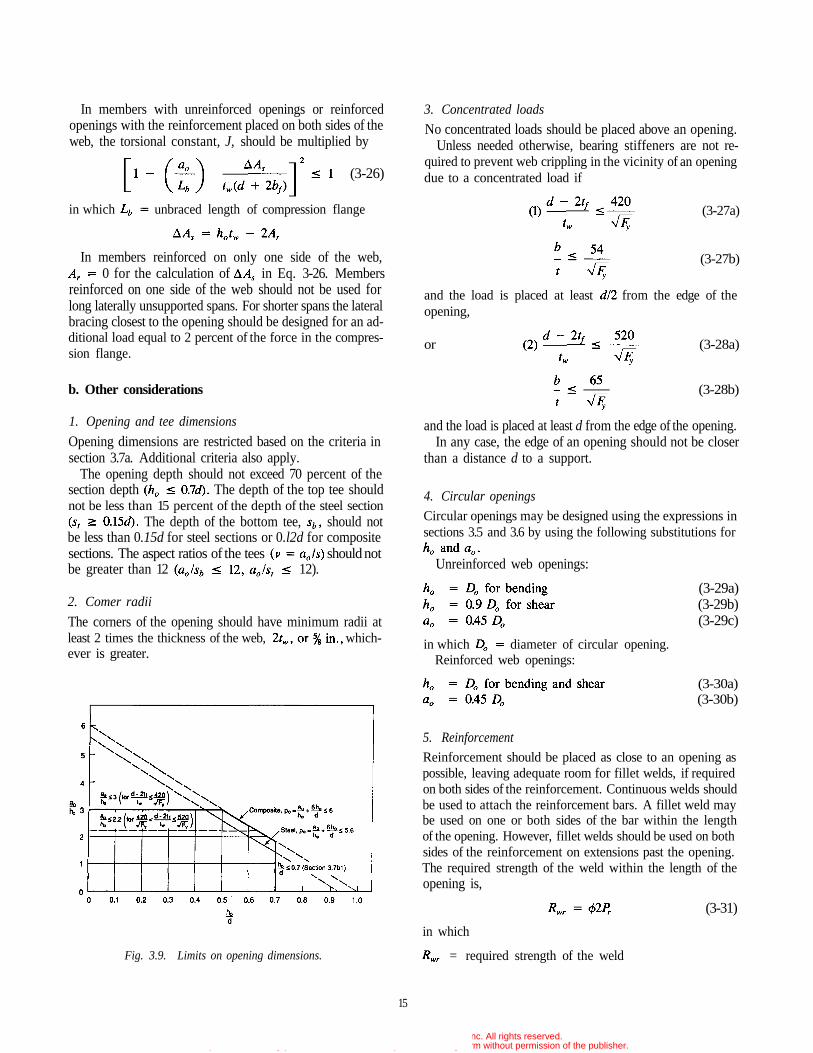
ling, along with an additional criterion from section 3.7bl,are summarized in Fig. 3.9.
3. Buckling of tee-shaped compression zone
For steel beams only: The tee which is in compression shouldbe investigated as an axially loaded column following theprocedures of AISC (1986b). For unreinforced members thisis not required when the aspect ratio of the teeis less than or equal to 4. For reinforced openings, this checkis only required for large openings in regions of high moment.
4. Lateral buckling
For steel beams only: In members subject to lateral buck-ling of the compression flange, strength should not begoverned by strength at the opening (calculated without re-gard to lateral buckling).
(3-25)
in which = thickness of webIf the web qualifies as stocky.
In this case, the upper limit on is 3.0 and the upperlimit on (maximum nominal shear capacity) for non-composite sections is in which theplastic shear capacity of the unperforated web. For compositesections, this upper limit may be increased by whichequals whichever is less.All standard rolled W shapes (AISC 1986a) qualify as stockymembers.
If then shouldbe limited to 2.2, and should be limited to 0.45 forboth composite and non-composite members.
The limits on opening dimensions to prevent web buck-
© 2003 by American Institute of Steel Construction, Inc. All rights reserved.This publication or any part thereof must not be reproduced in any form without permission of the publisher.
15
3. Concentrated loads
No concentrated loads should be placed above an opening.Unless needed otherwise, bearing stiffeners are not re-
quired to prevent web crippling in the vicinity of an openingdue to a concentrated load if
(3-27a)
(3-27b)
and the load is placed at least from the edge of theopening,
or (3-28a)
(3-28b)
and the load is placed at least d from the edge of the opening.In any case, the edge of an opening should not be closer
than a distance d to a support.
4. Circular openings
Circular openings may be designed using the expressions insections 3.5 and 3.6 by using the following substitutions for
Unreinforced web openings:
(3-29a)(3-29b)(3-29c)
in which diameter of circular opening.Reinforced web openings:
(3-30a)(3-30b)
5. Reinforcement
Reinforcement should be placed as close to an opening aspossible, leaving adequate room for fillet welds, if requiredon both sides of the reinforcement. Continuous welds shouldbe used to attach the reinforcement bars. A fillet weld maybe used on one or both sides of the bar within the lengthof the opening. However, fillet welds should be used on bothsides of the reinforcement on extensions past the opening.The required strength of the weld within the length of theopening is,
(3-31)
in which
= required strength of the weld
In members with unreinforced openings or reinforcedopenings with the reinforcement placed on both sides of theweb, the torsional constant, J, should be multiplied by
(3-26)
in which unbraced length of compression flange
In members reinforced on only one side of the web,0 for the calculation of in Eq. 3-26. Members
reinforced on one side of the web should not be used forlong laterally unsupported spans. For shorter spans the lateralbracing closest to the opening should be designed for an ad-ditional load equal to 2 percent of the force in the compres-sion flange.
b. Other considerations
1. Opening and tee dimensions
Opening dimensions are restricted based on the criteria insection 3.7a. Additional criteria also apply.
The opening depth should not exceed 70 percent of thesection depth The depth of the top tee shouldnot be less than 15 percent of the depth of the steel section
The depth of the bottom tee, should notbe less than 0.15d for steel sections or 0.l2d for compositesections. The aspect ratios of the tees should notbe greater than 12 12).
2. Comer radii
The corners of the opening should have minimum radii atleast 2 times the thickness of the web, which-ever is greater.
Fig. 3.9. Limits on opening dimensions.
© 2003 by American Institute of Steel Construction, Inc. All rights reserved.This publication or any part thereof must not be reproduced in any form without permission of the publisher.
In addition to the requirements in Eqs. 3-37 and 3-38,openings in composite beams should be spaced so that
(3-39a)
(3-39b)
c. Additional criteria for composite beams
In addition to the guidelines presented above, compositemembers should meet the following criteria.
1. Slab reinforcement
Transverse and longitudinal slab reinforcement ratios shouldbe a minimum of 0.0025, based on the gross area of the slab,within a distance d or whichever is greater, of the open-ing. For beams with longitudinal ribs, the transverse rein-forcement should be below the heads of the shear connectors.
2. Shear connectors
In addition to the shear connectors used between the highmoment end of the opening and the support, a minimum oftwo studs per foot should be used for a distance d orwhichever is greater, from the high moment end of the open-ing toward the direction of increasing moment.
3. Construction loads
If a composite beam is to be constructed without shoring,the section at the web opening should be checked for ade-quate strength as a non-composite member under factoreddead and construction loads.
3.8 ALLOWABLE STRESS DESIGN
The safe and accurate design of members with web open-ings requires that an ultimate strength approach be used. Toaccommodate members designed using ASD, the expressionspresented in this chapter should be used with = 1.00 anda load factor of 1.7 for both dead and live loads. These fac-tors are in accord with the Plastic Design Provisions of theAISC ASD Specification (1978).
= 0.90 for steel beams and 0.85 for composite beams
= cross-sectional area of reinforcement above or be-low the opening.
The reinforcement should be extended beyond the open-ing by a distance whichever isgreater, on each side of the opening (Figs 3.3 and 3.4). Withineach extension, the required strength of the weld is
(3-32)
If reinforcing bars are used on only one side of theweb, the section should meet the following additionalrequirements.
(3-33)
(3-34)
(3-35)
(3-36)
in which = area of flange= factored moment and shear at centerline of
opening, respectively.
6. Spacing of openings
Openings should be spaced in accordance with the follow-ing criteria to avoid interaction between openings.
Rectangular openings: (3-37a)
(3-37b)
Circular openings: (3-38a)
(3-38b)
in which S = clear space between openings.
16
Rev.3/1/03
Rev.3/1/03
© 2003 by American Institute of Steel Construction, Inc. All rights reserved.This publication or any part thereof must not be reproduced in any form without permission of the publisher.
Chapter 4
DESIGN SUMMARIES AND EXAMPLE PROBLEMS
4.1 GENERAL
Equations for maximum bending capacity and details ofopening design depend on the presence or absence of a com-posite slab and opening reinforcement. However, the over-all approach, the basic shear strength expressions, and theprocedures for handling the interaction of bending and shearare identical for all combinations of beam type and openingconfiguration. Thus, techniques that are applied in the de-sign of one type of opening can be applied to the design of all.
Tables 4.1 through 4.4 summarize the design sequence, de-sign equations and design aids that apply to steel beams withunreinforced openings, steel beams with reinforced openings,composite beams with unreinforced openings, and compos-ite beams with reinforced openings, respectively. Table 4.5
summarizes proportioning and detailing guidelines that ap-ply to all beams.
Sections 4.2 through 4.6 present design examples. The ex-amples in sections 4.2, 4.4, 4.5, and 4.6 follow the LRFDapproach. In section 4.3, the example in section 4.2 is re-solved using the ASD approach presented in section 3.8.
A typical design sequence involves cataloging the proper-ties of the section, calculating appropriate properties of theopening and the tees, and checking these properties as de-scribed in sections 3.7a and b. The strength of a section isdetermined by calculating the maximum moment and shearcapacities and then using the interaction curve (Fig. A.1) todetermine the strength at the opening under the combinedeffects of bending and shear.
Designs are completed by checking for conformance withadditional criteria in sections 3.7b and c.
17
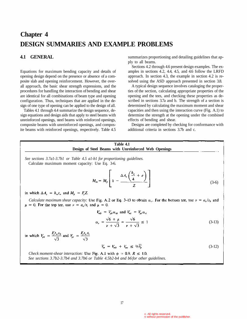
Table 4.1Design of Steel Beams with Unreinforced Web Openings
See sections 3.7a1-3.7b1 or Table 4.5 a1-b1 for proportioning guidelines.Calculate maximum moment capacity: Use Eq. 3-6.
(3-6)
(3-13)
(3-12)
Calculate maximum shear capacity:
Check moment-shear interaction:See sections 3.7b2-3.7b4 and 3.7b6 or Table 4.5b2-b4 and b6 for other guidelines.
© 2003 by American Institute of Steel Construction, Inc. All rights reserved.This publication or any part thereof must not be reproduced in any form without permission of the publisher.
18
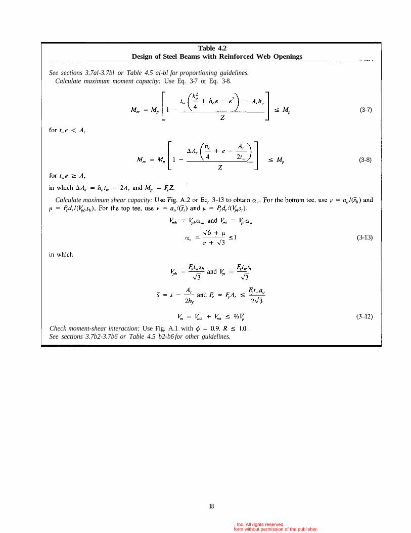
Table 4.2Design of Steel Beams with Reinforced Web Openings
(3-7)
(3-8)
(3-13)
See sections 3.7al-3.7bl or Table 4.5 al-bl for proportioning guidelines.Calculate maximum moment capacity: Use Eq. 3-7 or Eq. 3-8.
Check moment-shear interaction: Use Fig. A.1 withSee sections 3.7b2-3.7b6 or Table 4.5 b2-b6 for other guidelines.
Calculate maximum shear capacity:
© 2003 by American Institute of Steel Construction, Inc. All rights reserved.This publication or any part thereof must not be reproduced in any form without permission of the publisher.
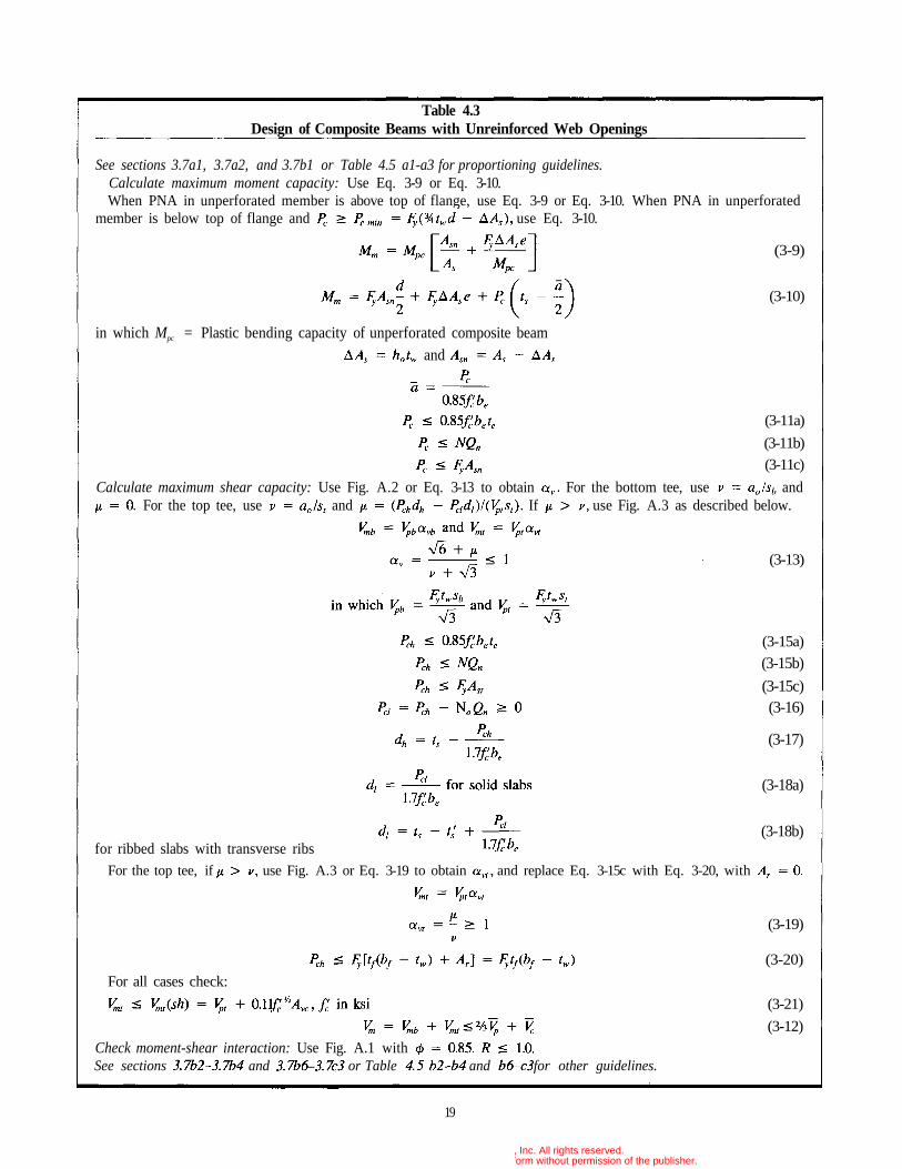
Table 4.3Design of Composite Beams with Unreinforced Web Openings
See sections 3.7a1, 3.7a2, and 3.7b1 or Table 4.5 a1-a3 for proportioning guidelines.Calculate maximum moment capacity: Use Eq. 3-9 or Eq. 3-10.When PNA in unperforated member is above top of flange, use Eq. 3-9 or Eq. 3-10. When PNA in unperforated
member is below top of flange and use Eq. 3-10.
(3-9)
(3-10)
in which Mpc = Plastic bending capacity of unperforated composite beamand
(3-11a)
(3-11b)(3-11c)
Calculate maximum shear capacity: Use Fig. A.2 or Eq. 3-13 to obtain For the bottom tee, use andFor the top tee, use and If use Fig. A.3 as described below.
(3-13)
(3-15a)
(3-15b)
(3-15c)(3-16)
(3-17)
(3-18a)
(3-18b)for ribbed slabs with transverse ribs
For the top tee, if use Fig. A.3 or Eq. 3-19 to obtain and replace Eq. 3-15c with Eq. 3-20, with
(3-19)
(3-20)
For all cases check:
(3-21)
(3-12)Check moment-shear interaction: Use Fig. A.1 withSee sections and or Table and for other guidelines.
19
© 2003 by American Institute of Steel Construction, Inc. All rights reserved.This publication or any part thereof must not be reproduced in any form without permission of the publisher.
20
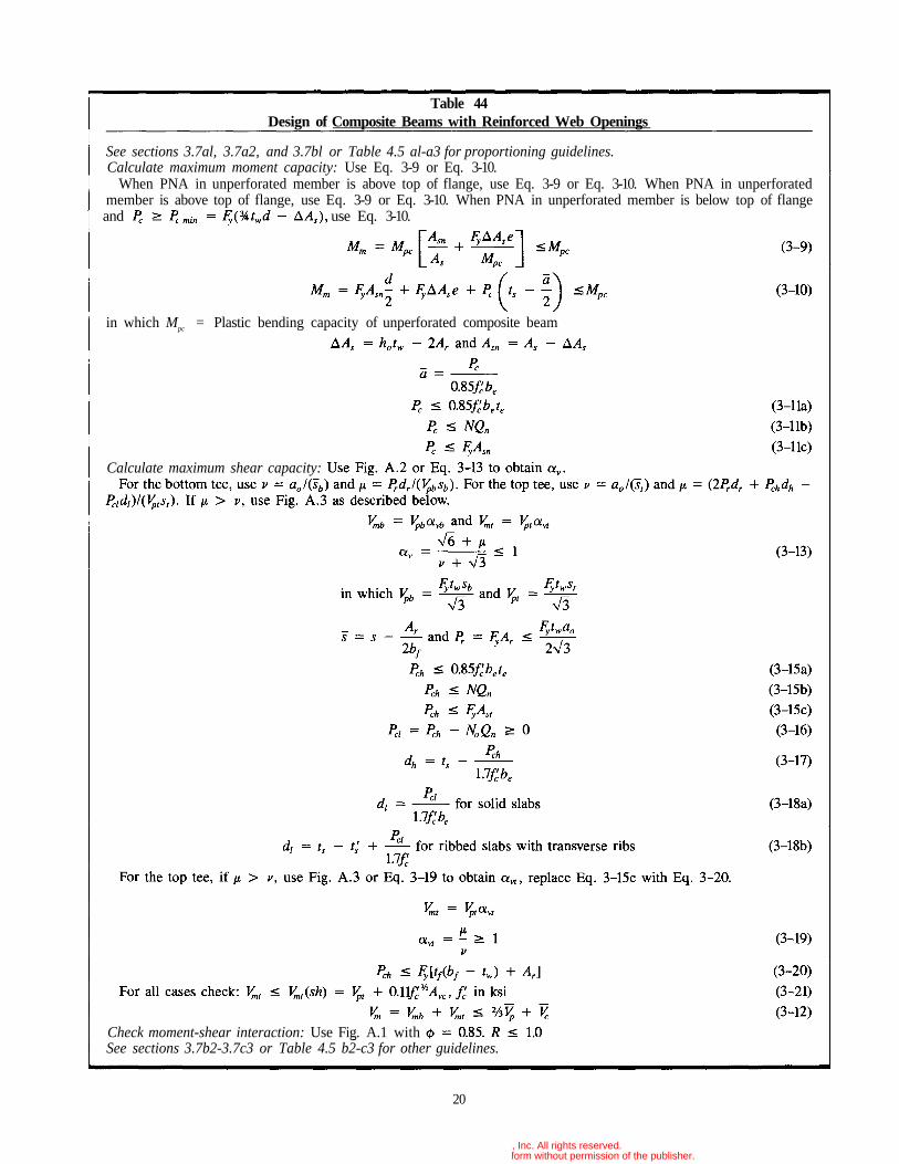
Table 44Design of Composite Beams with Reinforced Web Openings
See sections 3.7al, 3.7a2, and 3.7bl or Table 4.5 al-a3 for proportioning guidelines.Calculate maximum moment capacity: Use Eq. 3-9 or Eq. 3-10.
When PNA in unperforated member is above top of flange, use Eq. 3-9 or Eq. 3-10. When PNA in unperforatedmember is above top of flange, use Eq. 3-9 or Eq. 3-10. When PNA in unperforated member is below top of flangeand use Eq. 3-10.
in which Mpc = Plastic bending capacity of unperforated composite beam
Calculate maximum shear capacity:
Check moment-shear interaction: Use Fig. A.1 withSee sections 3.7b2-3.7c3 or Table 4.5 b2-c3 for other guidelines.
© 2003 by American Institute of Steel Construction, Inc. All rights reserved.This publication or any part thereof must not be reproduced in any form without permission of the publisher.
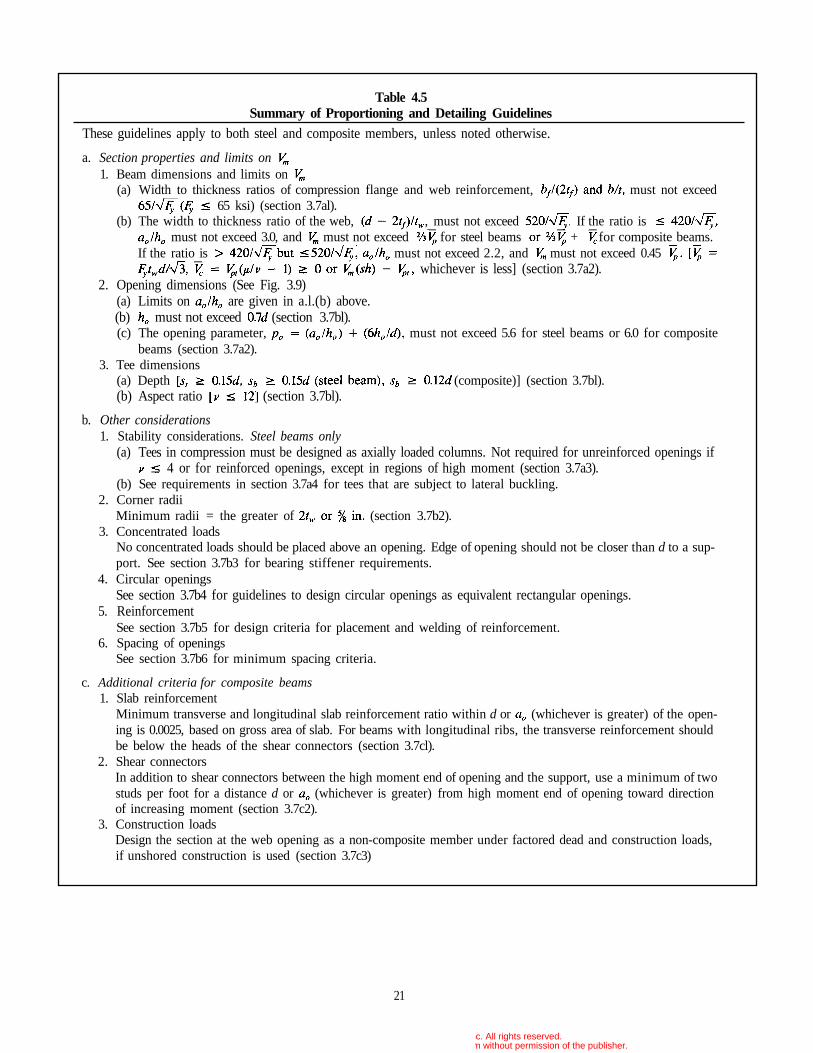
Table 4.5Summary of Proportioning and Detailing Guidelines
These guidelines apply to both steel and composite members, unless noted otherwise.
a. Section properties and limits on1. Beam dimensions and limits on
(a) Width to thickness ratios of compression flange and web reinforcement, must not exceed65 ksi) (section 3.7al).
(b) The width to thickness ratio of the web, , must not exceed . If the ratio ismust not exceed 3.0, and must not exceed for steel beams + for composite beams.
If the ratio is must not exceed 2.2, and must not exceed 0.45whichever is less] (section 3.7a2).
2. Opening dimensions (See Fig. 3.9)(a) Limits on are given in a.l.(b) above.(b) must not exceed (section 3.7bl).(c) The opening parameter, must not exceed 5.6 for steel beams or 6.0 for composite
beams (section 3.7a2).3. Tee dimensions
(a) Depth (composite)] (section 3.7bl).(b) Aspect ratio (section 3.7bl).
b. Other considerations1. Stability considerations. Steel beams only
(a) Tees in compression must be designed as axially loaded columns. Not required for unreinforced openings if4 or for reinforced openings, except in regions of high moment (section 3.7a3).
(b) See requirements in section 3.7a4 for tees that are subject to lateral buckling.2. Corner radii
Minimum radii = the greater of (section 3.7b2).3. Concentrated loads
No concentrated loads should be placed above an opening. Edge of opening should not be closer than d to a sup-port. See section 3.7b3 for bearing stiffener requirements.
4. Circular openingsSee section 3.7b4 for guidelines to design circular openings as equivalent rectangular openings.
5. ReinforcementSee section 3.7b5 for design criteria for placement and welding of reinforcement.
6. Spacing of openingsSee section 3.7b6 for minimum spacing criteria.
c. Additional criteria for composite beams1. Slab reinforcement
Minimum transverse and longitudinal slab reinforcement ratio within d or (whichever is greater) of the open-ing is 0.0025, based on gross area of slab. For beams with longitudinal ribs, the transverse reinforcement shouldbe below the heads of the shear connectors (section 3.7cl).
2. Shear connectorsIn addition to shear connectors between the high moment end of opening and the support, use a minimum of twostuds per foot for a distance d or (whichever is greater) from high moment end of opening toward directionof increasing moment (section 3.7c2).
3. Construction loadsDesign the section at the web opening as a non-composite member under factored dead and construction loads,if unshored construction is used (section 3.7c3)
21
© 2003 by American Institute of Steel Construction, Inc. All rights reserved.This publication or any part thereof must not be reproduced in any form without permission of the publisher.
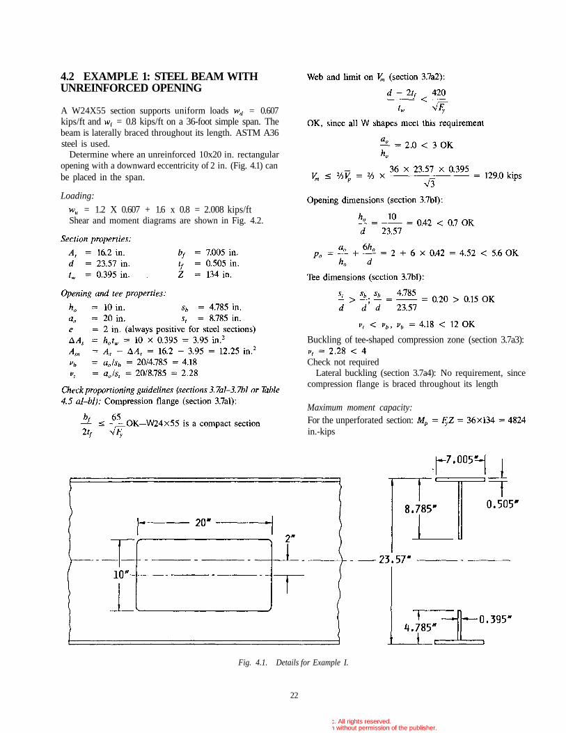
4.2 EXAMPLE 1: STEEL BEAM WITHUNREINFORCED OPENING
A W24X55 section supports uniform loads = 0.607kips/ft and = 0.8 kips/ft on a 36-foot simple span. Thebeam is laterally braced throughout its length. ASTM A36steel is used.
Determine where an unreinforced 10x20 in. rectangularopening with a downward eccentricity of 2 in. (Fig. 4.1) canbe placed in the span.
Loading:
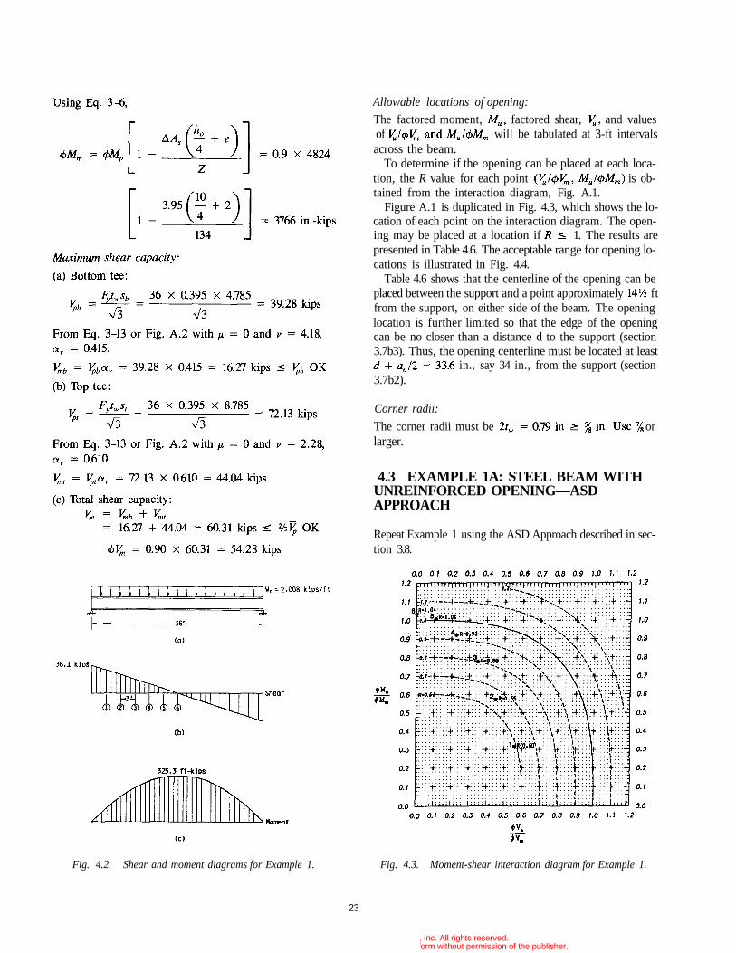
= 1.2 X 0.607 + 1.6 x 0.8 = 2.008 kips/ftShear and moment diagrams are shown in Fig. 4.2.
Buckling of tee-shaped compression zone (section 3.7a3):
Check not requiredLateral buckling (section 3.7a4): No requirement, since
compression flange is braced throughout its length
Maximum moment capacity:For the unperforated section:in.-kips
Fig. 4.1. Details for Example I.
22
© 2003 by American Institute of Steel Construction, Inc. All rights reserved.This publication or any part thereof must not be reproduced in any form without permission of the publisher.
Allowable locations of opening:
The factored moment, factored shear, and valuesof will be tabulated at 3-ft intervalsacross the beam.
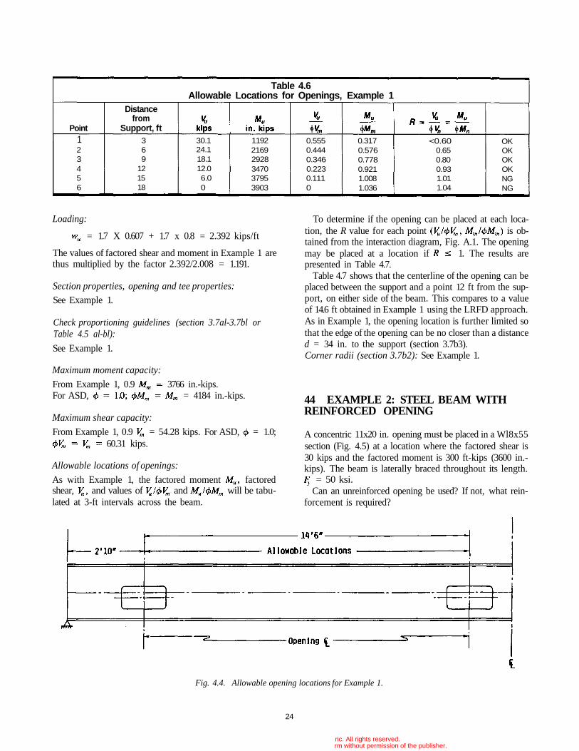
To determine if the opening can be placed at each loca-tion, the R value for each point is ob-tained from the interaction diagram, Fig. A.1.
Figure A.1 is duplicated in Fig. 4.3, which shows the lo-cation of each point on the interaction diagram. The open-ing may be placed at a location if 1. The results arepresented in Table 4.6. The acceptable range for opening lo-cations is illustrated in Fig. 4.4.
Table 4.6 shows that the centerline of the opening can beplaced between the support and a point approximately ftfrom the support, on either side of the beam. The openinglocation is further limited so that the edge of the openingcan be no closer than a distance d to the support (section3.7b3). Thus, the opening centerline must be located at least
in., say 34 in., from the support (section3.7b2).
Corner radii:
The corner radii must be orlarger.
4.3 EXAMPLE 1A: STEEL BEAM WITHUNREINFORCED OPENING—ASDAPPROACH
Repeat Example 1 using the ASD Approach described in sec-tion 3.8.
Fig. 4.2. Shear and moment diagrams for Example 1. Fig. 4.3. Moment-shear interaction diagram for Example 1.
23
© 2003 by American Institute of Steel Construction, Inc. All rights reserved.This publication or any part thereof must not be reproduced in any form without permission of the publisher.
Loading:
= 1.7 X 0.607 + 1.7 x 0.8 = 2.392 kips/ft
The values of factored shear and moment in Example 1 arethus multiplied by the factor 2.392/2.008 = 1.191.
Section properties, opening and tee properties:
See Example 1.
Check proportioning guidelines (section 3.7al-3.7bl orTable 4.5 al-bl):
See Example 1.
Maximum moment capacity:
From Example 1, 0.9 3766 in.-kips.For ASD, = 4184 in.-kips.
Maximum shear capacity:
From Example 1, 0.9 = 54.28 kips. For ASD, = 1.0;60.31 kips.
Allowable locations of openings:
As with Example 1, the factored moment factoredshear, and values of and will be tabu-lated at 3-ft intervals across the beam.
To determine if the opening can be placed at each loca-tion, the R value for each point is ob-tained from the interaction diagram, Fig. A.1. The openingmay be placed at a location if 1. The results arepresented in Table 4.7.
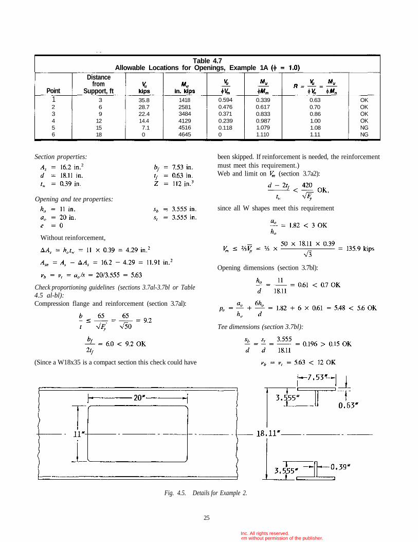
Table 4.7 shows that the centerline of the opening can beplaced between the support and a point 12 ft from the sup-port, on either side of the beam. This compares to a valueof 14.6 ft obtained in Example 1 using the LRFD approach.As in Example 1, the opening location is further limited sothat the edge of the opening can be no closer than a distanced = 34 in. to the support (section 3.7b3).Corner radii (section 3.7b2): See Example 1.
44 EXAMPLE 2: STEEL BEAM WITHREINFORCED OPENING
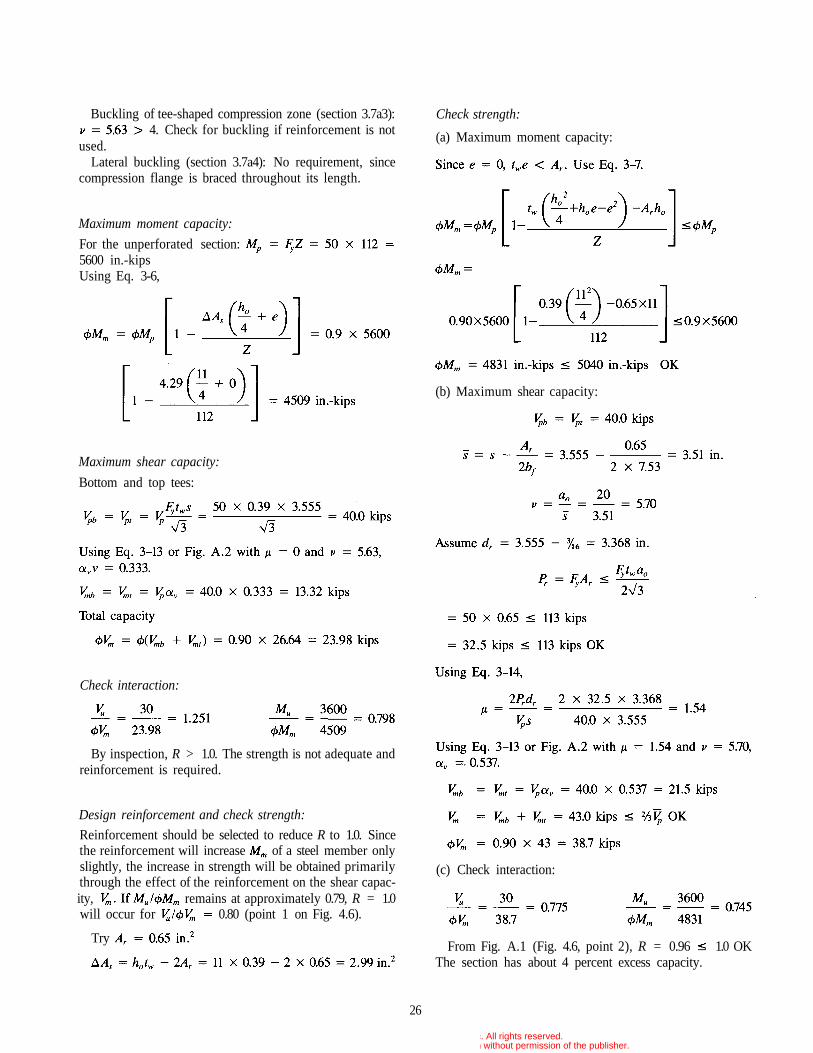
A concentric 11x20 in. opening must be placed in a Wl8x55section (Fig. 4.5) at a location where the factored shear is30 kips and the factored moment is 300 ft-kips (3600 in.-kips). The beam is laterally braced throughout its length.
= 50 ksi.Can an unreinforced opening be used? If not, what rein-
forcement is required?
Fig. 4.4. Allowable opening locations for Example 1.
24
Table 4.6Allowable Locations for Openings, Example 1
Point
Distancefrom
Support, ft123456
369
121518
30.124.118.112.06.00
119221692928347037953903
0.5550.4440.3460.2230.1110
0.3170.5760.7780.9211.0081.036
<0.600.650.800.931.011.04
OKOKOKOKNGNG
© 2003 by American Institute of Steel Construction, Inc. All rights reserved.This publication or any part thereof must not be reproduced in any form without permission of the publisher.
been skipped. If reinforcement is needed, the reinforcementmust meet this requirement.)Web and limit on (section 3.7a2):
Fig. 4.5. Details for Example 2.
25
123456
369
121518
35.828.722.414.47.10
141825813484412945164645
0.5940.4760.3710.2390.1180
0.3390.6170.8330.9871.0791.110
0.630.700.861.001.081.11
OKOKOKOKNGNG
Table 4.7Allowable Locations for Openings, Example 1A
Point
Distancefrom
Support, ft
Section properties:
Opening and tee properties:
Without reinforcement,
since all W shapes meet this requirement
Check proportioning guidelines (sections 3.7al-3.7bl or Table4.5 al-bl):Compression flange and reinforcement (section 3.7al):
(Since a W18x35 is a compact section this check could have
Opening dimensions (section 3.7bl):
Tee dimensions (section 3.7bl):
© 2003 by American Institute of Steel Construction, Inc. All rights reserved.This publication or any part thereof must not be reproduced in any form without permission of the publisher.
Buckling of tee-shaped compression zone (section 3.7a3):4. Check for buckling if reinforcement is not
used.Lateral buckling (section 3.7a4): No requirement, since
compression flange is braced throughout its length.
Maximum moment capacity:
For the unperforated section:5600 in.-kipsUsing Eq. 3-6,
Design reinforcement and check strength:
Reinforcement should be selected to reduce R to 1.0. Sincethe reinforcement will increase of a steel member onlyslightly, the increase in strength will be obtained primarilythrough the effect of the reinforcement on the shear capac-ity, remains at approximately 0.79, R = 1.0will occur for 0.80 (point 1 on Fig. 4.6).
TryFrom Fig. A.1 (Fig. 4.6, point 2), R = 0.96 1.0 OK
The section has about 4 percent excess capacity.
26
Maximum shear capacity:
Bottom and top tees:
Check interaction:
By inspection, R > 1.0. The strength is not adequate andreinforcement is required.
Check strength:
(a) Maximum moment capacity:
(b) Maximum shear capacity:
(c) Check interaction:
© 2003 by American Institute of Steel Construction, Inc. All rights reserved.This publication or any part thereof must not be reproduced in any form without permission of the publisher.
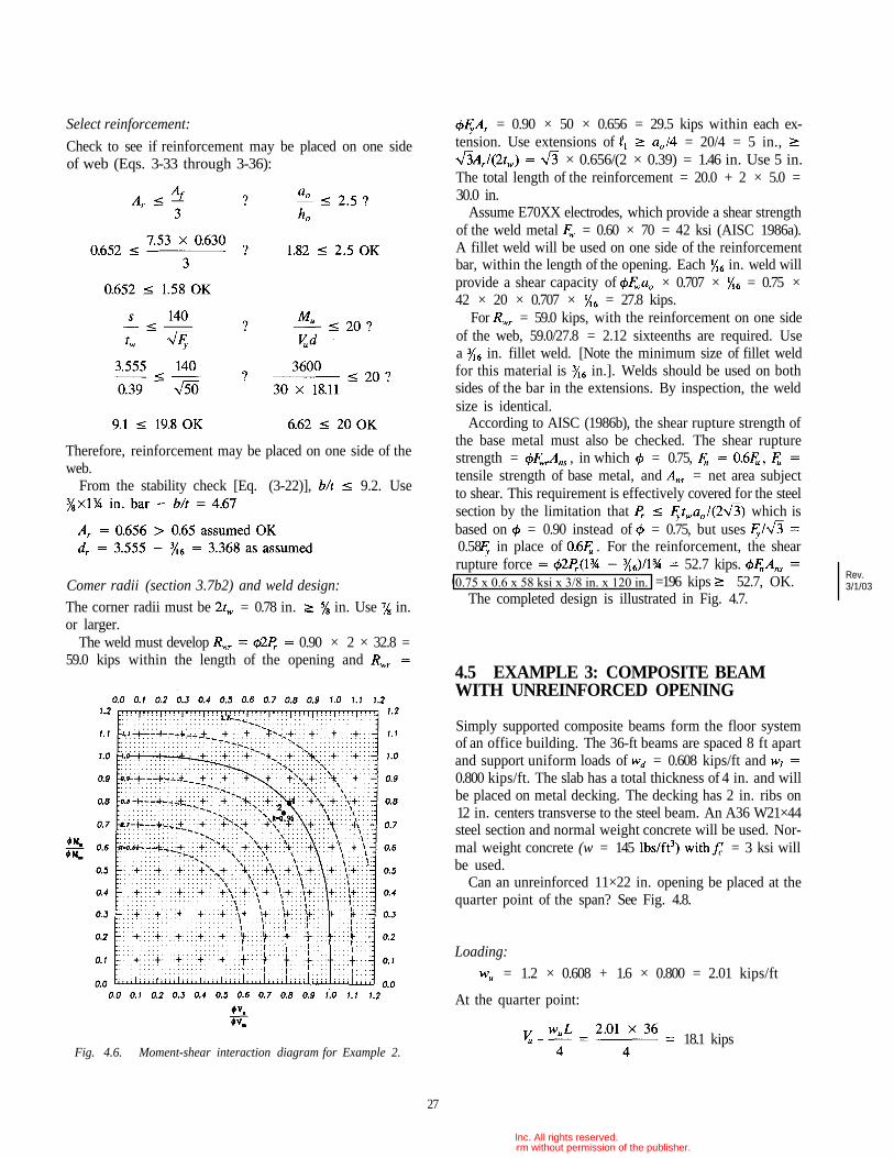
= 0.90 × 50 × 0.656 = 29.5 kips within each ex-tension. Use extensions of = 20/4 = 5 in.,
× 0.656/(2 × 0.39) = 1.46 in. Use 5 in.The total length of the reinforcement = 20.0 + 2 × 5.0 =30.0 in.
Assume E70XX electrodes, which provide a shear strengthof the weld metal = 0.60 × 70 = 42 ksi (AISC 1986a).A fillet weld will be used on one side of the reinforcementbar, within the length of the opening. Each in. weld willprovide a shear capacity of × 0.707 × = 0.75 ×42 × 20 × 0.707 × = 27.8 kips.
For = 59.0 kips, with the reinforcement on one sideof the web, 59.0/27.8 = 2.12 sixteenths are required. Usea in. fillet weld. [Note the minimum size of fillet weldfor this material is in.]. Welds should be used on bothsides of the bar in the extensions. By inspection, the weldsize is identical.
According to AISC (1986b), the shear rupture strength ofthe base metal must also be checked. The shear rupturestrength = , in which = 0.75,tensile strength of base metal, and = net area subjectto shear. This requirement is effectively covered for the steelsection by the limitation that which isbased on = 0.90 instead of = 0.75, but uses0.58 in place of . For the reinforcement, the shearrupture force 52.7 kips.
0.75 × 0.6 × 58 ksi × in. = =196 kips 52.7, OK.The completed design is illustrated in Fig. 4.7.
4.5 EXAMPLE 3: COMPOSITE BEAMWITH UNREINFORCED OPENING
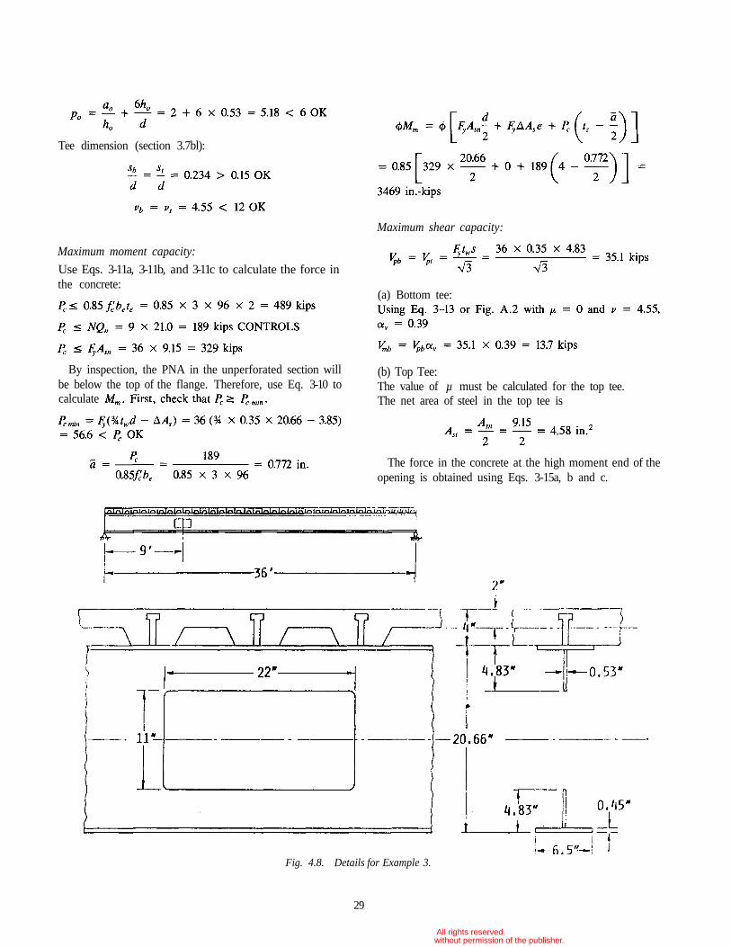
Simply supported composite beams form the floor systemof an office building. The 36-ft beams are spaced 8 ft apartand support uniform loads of = 0.608 kips/ft and0.800 kips/ft. The slab has a total thickness of 4 in. and willbe placed on metal decking. The decking has 2 in. ribs on12 in. centers transverse to the steel beam. An A36 W21×44steel section and normal weight concrete will be used. Nor-mal weight concrete (w = 145 = 3 ksi willbe used.
Can an unreinforced 11×22 in. opening be placed at thequarter point of the span? See Fig. 4.8.
27
Select reinforcement:
Check to see if reinforcement may be placed on one sideof web (Eqs. 3-33 through 3-36):
Fig. 4.6. Moment-shear interaction diagram for Example 2.
Therefore, reinforcement may be placed on one side of theweb.
From the stability check [Eq. (3-22)], 9.2. Use
Comer radii (section 3.7b2) and weld design:
The corner radii must be = 0.78 in. in. Use in.or larger.
The weld must develop 0.90 × 2 × 32.8 =59.0 kips within the length of the opening and
Loading:
= 1.2 × 0.608 + 1.6 × 0.800 = 2.01 kips/ft
At the quarter point:
18.1 kips
Rev.3/1/03
© 2003 by American Institute of Steel Construction, Inc. All rights reserved.This publication or any part thereof must not be reproduced in any form without permission of the publisher.
0.75 x 0.6 x 58 ksi x 3/8 in. x 120 in.
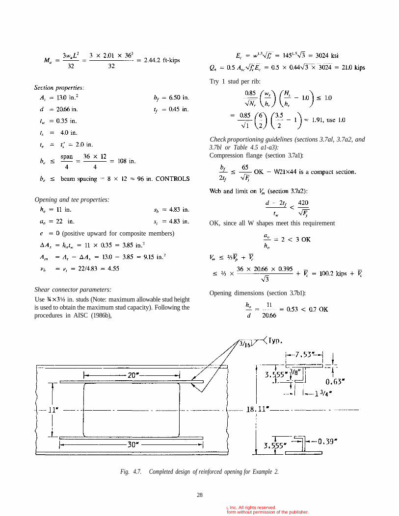
Fig. 4.7. Completed design of reinforced opening for Example 2.
28
Shear connector parameters:
Use in. studs (Note: maximum allowable stud heightis used to obtain the maximum stud capacity). Following theprocedures in AISC (1986b),
Opening and tee properties:
(positive upward for composite members)
Try 1 stud per rib:
Check proportioning guidelines (sections 3.7al, 3.7a2, and3.7bl or Table 4.5 a1-a3):Compression flange (section 3.7a1):
OK, since all W shapes meet this requirement
Opening dimensions (section 3.7b1):
© 2003 by American Institute of Steel Construction, Inc. All rights reserved.This publication or any part thereof must not be reproduced in any form without permission of the publisher.
29
Tee dimension (section 3.7bl):
Maximum moment capacity:
Use Eqs. 3-11a, 3-11b, and 3-11c to calculate the force inthe concrete:
By inspection, the PNA in the unperforated section willbe below the top of the flange. Therefore, use Eq. 3-10 tocalculate
Maximum shear capacity:
(a) Bottom tee:
(b) Top Tee:The value of µ must be calculated for the top tee.The net area of steel in the top tee is
The force in the concrete at the high moment end of theopening is obtained using Eqs. 3-15a, b and c.
Fig. 4.8. Details for Example 3.
© 2003 by American Institute of Steel Construction, Inc. All rights reserved.This publication or any part thereof must not be reproduced in any form without permission of the publisher.
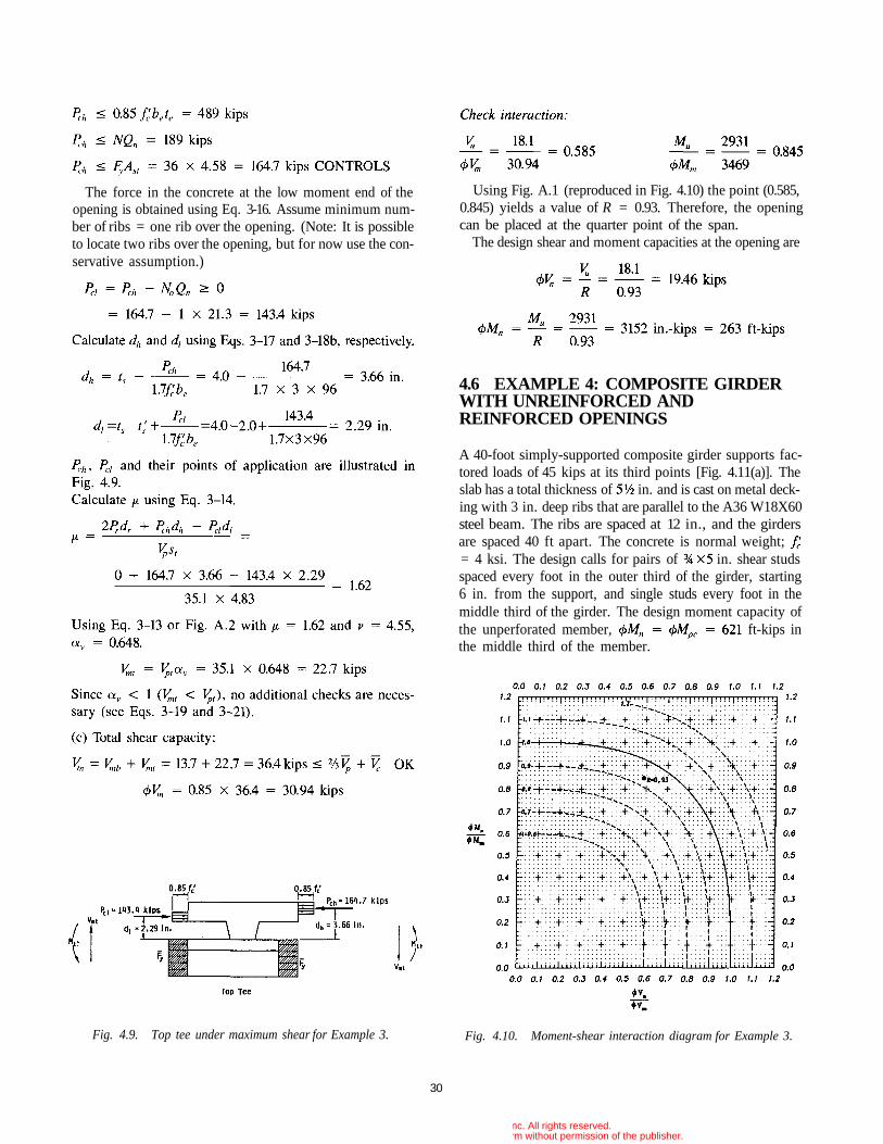
Fig. 4.9. Top tee under maximum shear for Example 3. Fig. 4.10. Moment-shear interaction diagram for Example 3.
30
Using Fig. A.1 (reproduced in Fig. 4.10) the point (0.585,0.845) yields a value of R = 0.93. Therefore, the openingcan be placed at the quarter point of the span.
The design shear and moment capacities at the opening are
4.6 EXAMPLE 4: COMPOSITE GIRDERWITH UNREINFORCED ANDREINFORCED OPENINGS
A 40-foot simply-supported composite girder supports fac-tored loads of 45 kips at its third points [Fig. 4.11(a)]. Theslab has a total thickness of in. and is cast on metal deck-ing with 3 in. deep ribs that are parallel to the A36 W18X60steel beam. The ribs are spaced at 12 in., and the girdersare spaced 40 ft apart. The concrete is normal weight;= 4 ksi. The design calls for pairs of in. shear studsspaced every foot in the outer third of the girder, starting6 in. from the support, and single studs every foot in themiddle third of the girder. The design moment capacity ofthe unperforated member, ft-kips inthe middle third of the member.
The force in the concrete at the low moment end of theopening is obtained using Eq. 3-16. Assume minimum num-ber of ribs = one rib over the opening. (Note: It is possibleto locate two ribs over the opening, but for now use the con-servative assumption.)
© 2003 by American Institute of Steel Construction, Inc. All rights reserved.This publication or any part thereof must not be reproduced in any form without permission of the publisher.
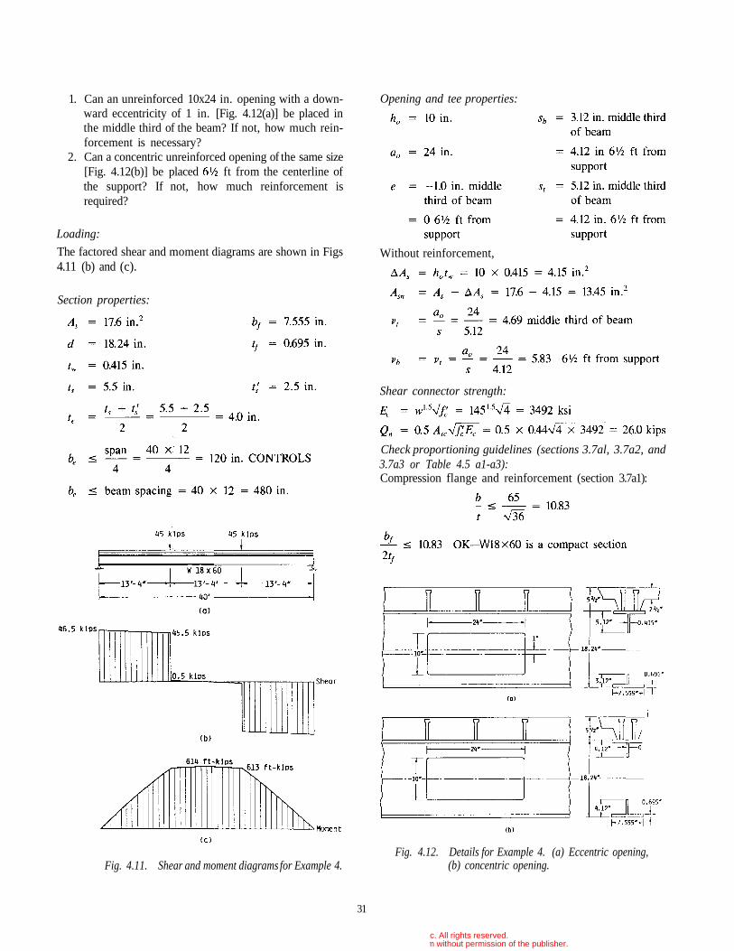
1. Can an unreinforced 10x24 in. opening with a down-ward eccentricity of 1 in. [Fig. 4.12(a)] be placed inthe middle third of the beam? If not, how much rein-forcement is necessary?
2. Can a concentric unreinforced opening of the same size[Fig. 4.12(b)] be placed ft from the centerline ofthe support? If not, how much reinforcement isrequired?
Loading:
The factored shear and moment diagrams are shown in Figs4.11 (b) and (c).
Fig. 4.11. Shear and moment diagrams for Example 4.Fig. 4.12. Details for Example 4. (a) Eccentric opening,
(b) concentric opening.
31
Section properties:
Opening and tee properties:
Without reinforcement,
Shear connector strength:
Check proportioning guidelines (sections 3.7al, 3.7a2, and3.7a3 or Table 4.5 a1-a3):Compression flange and reinforcement (section 3.7a1):
© 2003 by American Institute of Steel Construction, Inc. All rights reserved.This publication or any part thereof must not be reproduced in any form without permission of the publisher.
in middle third OK, by inspection, ft from support
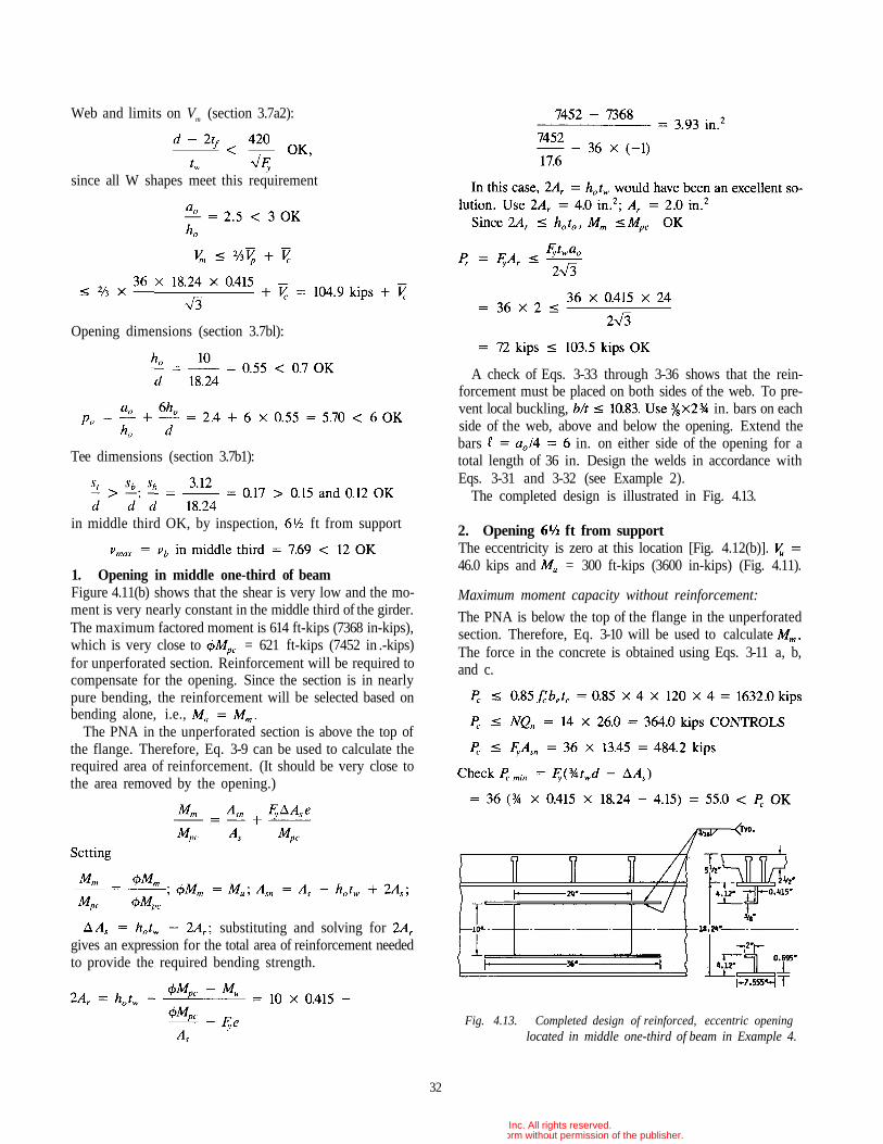
1. Opening in middle one-third of beamFigure 4.11(b) shows that the shear is very low and the mo-ment is very nearly constant in the middle third of the girder.The maximum factored moment is 614 ft-kips (7368 in-kips),which is very close to = 621 ft-kips (7452 in .-kips)for unperforated section. Reinforcement will be required tocompensate for the opening. Since the section is in nearlypure bending, the reinforcement will be selected based onbending alone, i.e.,
The PNA in the unperforated section is above the top ofthe flange. Therefore, Eq. 3-9 can be used to calculate therequired area of reinforcement. (It should be very close tothe area removed by the opening.)
Fig. 4.13. Completed design of reinforced, eccentric openinglocated in middle one-third of beam in Example 4.
32
A check of Eqs. 3-33 through 3-36 shows that the rein-forcement must be placed on both sides of the web. To pre-vent local buckling, in. bars on eachside of the web, above and below the opening. Extend thebars in. on either side of the opening for atotal length of 36 in. Design the welds in accordance withEqs. 3-31 and 3-32 (see Example 2).
The completed design is illustrated in Fig. 4.13.
2. Opening ft from supportThe eccentricity is zero at this location [Fig. 4.12(b)].46.0 kips and = 300 ft-kips (3600 in-kips) (Fig. 4.11).
Maximum moment capacity without reinforcement:
The PNA is below the top of the flange in the unperforatedsection. Therefore, Eq. 3-10 will be used to calculateThe force in the concrete is obtained using Eqs. 3-11 a, b,and c.
Web and limits on Vm (section 3.7a2):
since all W shapes meet this requirement
Opening dimensions (section 3.7bl):
Tee dimensions (section 3.7b1):
substituting and solving forgives an expression for the total area of reinforcement neededto provide the required bending strength.
© 2003 by American Institute of Steel Construction, Inc. All rights reserved.This publication or any part thereof must not be reproduced in any form without permission of the publisher.
(b) Top tee:The value of [Eq. 3-14] must be calculated for the top tee.
The force at the high moment end of the opening, isobtained using Eqs. 3-15a, b, and c. Noting that Eqs. 3-15aand b are the same as Eqs. 3-1 1a and b, the limitations basedon concrete and stud capacity are identical to those obtainedfor in the calculation of above. This leaves Eq.3-15c.
242 kips CONTROLS
The force in the concrete at the low moment end of theopening, is obtained using Eq. 3-16. With the shearstuds placed in pairs every foot, starting 6 in. from the cen-terline of the support, Note that the definitions forN and N0 require the studs to be completely within the ap-plicable range to be counted. This means that the studs lo-cated just at the ends of the opening are not included inand the studs at the high moment end of the opening are notcounted in N.
the distances from the top of the flange to thecentroids of respectively, are calculated usingEqs. 3-17 and 3-18a. Since the ribs are parallel to the steelbeams, in Eq. 3-18a is conservatively replaced bythe sum of the minimum rib widths that lie within
Since Eq. 3-19 or Fig A.3 should be used to calcu-late In addition, when is limited by the ten-sile capacity of the flange plus reinforcement (if any),Eq. 3-20.
This value is less than the current value of (242 kips).Therefore, must also be recalculated. Thenew values are as follows:
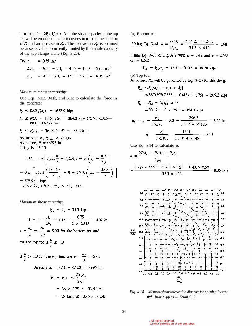
By inspection, the section does not have adequate strength.Using Fig A.1 (reproduced in Fig. 4.14), the point (1.114,0.674), point 1 on Fig. 4.14, yields a value of R = 1.21> 1.
Design reinforcement and check strength:
The addition of reinforcement will increase the capacity atthe opening in a number of ways: The moment capacity,
will be enhanced due to the increase The shear ca-pacity of the bottom tee will be enhanced due to the increase
33
© 2003 by American Institute of Steel Construction, Inc. All rights reserved.This publication or any part thereof must not be reproduced in any form without permission of the publisher.
in from 0 to And the shear capacity of the toptee will be enhanced due to increases in from the additionof and an increase in The increase in is obtainedbecause its value is currently limited by the tensile capacityof the top flange alone (Eq. 3-20).
Fig. 4.14. Moment-shear interaction diagram for opening locatedft from support in Example 4.
34
Maximum moment capacity:
Use Eqs. 3-11a, 3-11b, and 3-11c to calculate the force inthe concrete:
Maximum shear capacity:
(a) Bottom tee:
(b) Top tee:
Use Eq. 3-14 to calculate µ.
© 2003 by American Institute of Steel Construction, Inc. All rights reserved.This publication or any part thereof must not be reproduced in any form without permission of the publisher.
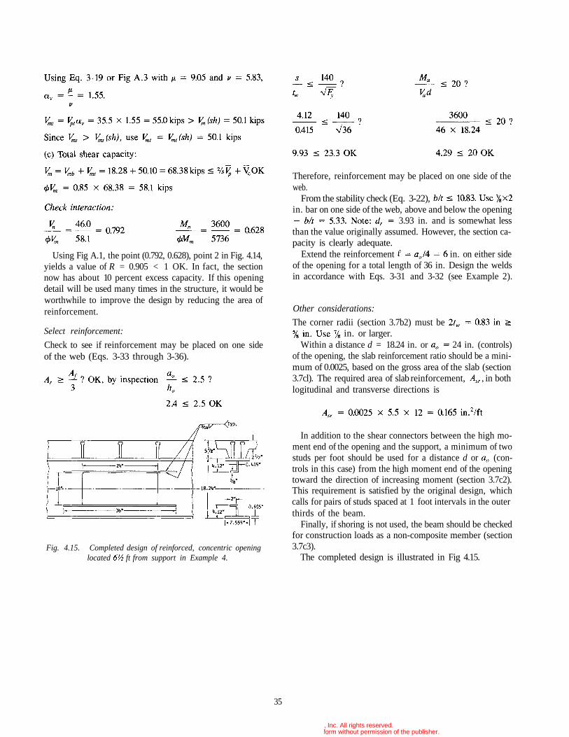
Using Fig A.1, the point (0.792, 0.628), point 2 in Fig. 4.14,yields a value of R = 0.905 < 1 OK. In fact, the sectionnow has about 10 percent excess capacity. If this openingdetail will be used many times in the structure, it would beworthwhile to improve the design by reducing the area ofreinforcement.
Select reinforcement:
Check to see if reinforcement may be placed on one sideof the web (Eqs. 3-33 through 3-36).
Fig. 4.15. Completed design of reinforced, concentric openinglocated ft from support in Example 4.
Therefore, reinforcement may be placed on one side of theweb.
From the stability check (Eq. 3-22),in. bar on one side of the web, above and below the opening
3.93 in. and is somewhat lessthan the value originally assumed. However, the section ca-pacity is clearly adequate.
Extend the reinforcement in. on either sideof the opening for a total length of 36 in. Design the weldsin accordance with Eqs. 3-31 and 3-32 (see Example 2).
Other considerations:
The corner radii (section 3.7b2) must bein. or larger.
Within a distance d = 18.24 in. or 24 in. (controls)of the opening, the slab reinforcement ratio should be a mini-mum of 0.0025, based on the gross area of the slab (section3.7cl). The required area of slab reinforcement, in bothlogitudinal and transverse directions is
In addition to the shear connectors between the high mo-ment end of the opening and the support, a minimum of twostuds per foot should be used for a distance d or (con-trols in this case) from the high moment end of the openingtoward the direction of increasing moment (section 3.7c2).This requirement is satisfied by the original design, whichcalls for pairs of studs spaced at 1 foot intervals in the outerthirds of the beam.
Finally, if shoring is not used, the beam should be checkedfor construction loads as a non-composite member (section3.7c3).
The completed design is illustrated in Fig 4.15.
35
© 2003 by American Institute of Steel Construction, Inc. All rights reserved.This publication or any part thereof must not be reproduced in any form without permission of the publisher.
Chapter 5
BACKGROUND AND COMMENTARY
5.1 GENERAL
This chapter provides the background and commentary forthe design procedures presented in Chapter 3. Sections 5.2athrough 5.2g summarize the behavior of steel and compos-ite beams with web openings, including the effects of open-ings on stress distributions, modes of failure, and the gen-eral response of members to loading. Section 5.2h providesthe commentary for section 3.2 on load and resistance fac-tors, while sections 5.3 through 5.7 provide the commentaryfor sections 3.3 through 3.7 on design equations and guide-lines for proportioning and detailing beams with webopenings.
5.2 BEHAVIOR OF MEMBERS WITHWEB OPENINGS
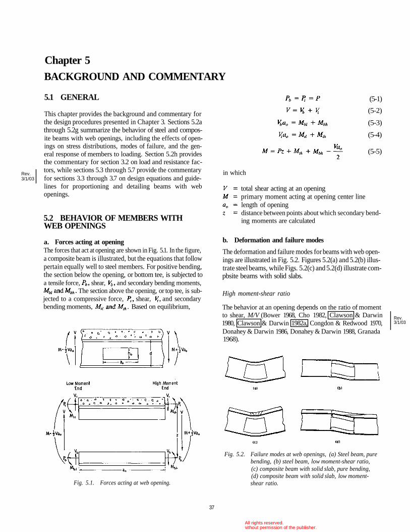
a. Forces acting at openingThe forces that act at opening are shown in Fig. 5.1. In the figure,a composite beam is illustrated, but the equations that followpertain equally well to steel members. For positive bending,the section below the opening, or bottom tee, is subjected toa tensile force, shear, and secondary bending moments,
The section above the opening, or top tee, is sub-jected to a compressive force, shear, and secondarybending moments, . Based on equilibrium,
b. Deformation and failure modes
The deformation and failure modes for beams with web open-ings are illustrated in Fig. 5.2. Figures 5.2(a) and 5.2(b) illus-trate steel beams, while Figs. 5.2(c) and 5.2(d) illustrate com-pbsite beams with solid slabs.
High moment-shear ratio
The behavior at an opening depends on the ratio of momentto shear, M/V (Bower 1968, Cho 1982, Clawson & Darwin1980, Clawson & Darwin 1982a, Congdon & Redwood 1970,Donahey & Darwin 1986, Donahey & Darwin 1988, Granada1968).
Fig. 5.2. Failure modes at web openings, (a) Steel beam, purebending, (b) steel beam, low moment-shear ratio,(c) composite beam with solid slab, pure bending,(d) composite beam with solid slab, low moment-shear ratio.
37
Fig. 5.1. Forces acting at web opening.
(5-1)
(5-2)
(5-3)
(5-4)
(5-5)
in which
total shear acting at an openingprimary moment acting at opening center linelength of openingdistance between points about which secondary bend-ing moments are calculated
Rev.3/1/03
Rev.3/1/03
© 2003 by American Institute of Steel Construction, Inc. All rights reserved.This publication or any part thereof must not be reproduced in any form without permission of the publisher.
Medium and low moment-shear ratioAs M/V decreases, shear and the secondary bending momentsincrease, causing increasing differential, or Vierendeel, defor-mation to occur through the opening [Figs. 5.2(b) and 5.2(d)].The top and bottom tees exhibit a well-defined change incurvature.
For steel beams [Fig. 5.2(b)], failure occurs with the for-mation of plastic hinges at all four corners of the opening.Yielding first occurs within the webs of the tees.
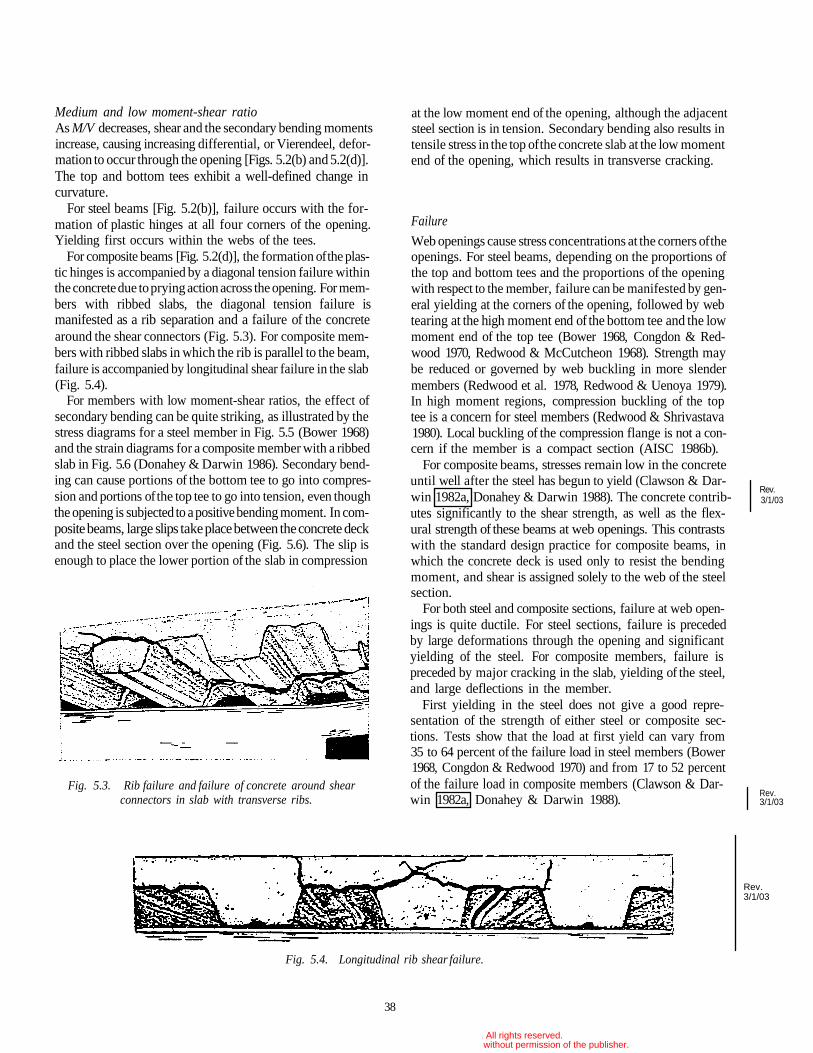
For composite beams [Fig. 5.2(d)], the formation of the plas-tic hinges is accompanied by a diagonal tension failure withinthe concrete due to prying action across the opening. For mem-bers with ribbed slabs, the diagonal tension failure ismanifested as a rib separation and a failure of the concretearound the shear connectors (Fig. 5.3). For composite mem-bers with ribbed slabs in which the rib is parallel to the beam,failure is accompanied by longitudinal shear failure in the slab(Fig. 5.4).
For members with low moment-shear ratios, the effect ofsecondary bending can be quite striking, as illustrated by thestress diagrams for a steel member in Fig. 5.5 (Bower 1968)and the strain diagrams for a composite member with a ribbedslab in Fig. 5.6 (Donahey & Darwin 1986). Secondary bend-ing can cause portions of the bottom tee to go into compres-sion and portions of the top tee to go into tension, even thoughthe opening is subjected to a positive bending moment. In com-posite beams, large slips take place between the concrete deckand the steel section over the opening (Fig. 5.6). The slip isenough to place the lower portion of the slab in compression
Fig. 5.3. Rib failure and failure of concrete around shearconnectors in slab with transverse ribs.
at the low moment end of the opening, although the adjacentsteel section is in tension. Secondary bending also results intensile stress in the top of the concrete slab at the low momentend of the opening, which results in transverse cracking.
Failure
Web openings cause stress concentrations at the corners of theopenings. For steel beams, depending on the proportions ofthe top and bottom tees and the proportions of the openingwith respect to the member, failure can be manifested by gen-eral yielding at the corners of the opening, followed by webtearing at the high moment end of the bottom tee and the lowmoment end of the top tee (Bower 1968, Congdon & Red-wood 1970, Redwood & McCutcheon 1968). Strength maybe reduced or governed by web buckling in more slendermembers (Redwood et al. 1978, Redwood & Uenoya 1979).In high moment regions, compression buckling of the toptee is a concern for steel members (Redwood & Shrivastava1980). Local buckling of the compression flange is not a con-cern if the member is a compact section (AISC 1986b).
For composite beams, stresses remain low in the concreteuntil well after the steel has begun to yield (Clawson & Dar-win 1982a, Donahey & Darwin 1988). The concrete contrib-utes significantly to the shear strength, as well as the flex-ural strength of these beams at web openings. This contrastswith the standard design practice for composite beams, inwhich the concrete deck is used only to resist the bendingmoment, and shear is assigned solely to the web of the steelsection.
For both steel and composite sections, failure at web open-ings is quite ductile. For steel sections, failure is precededby large deformations through the opening and significantyielding of the steel. For composite members, failure ispreceded by major cracking in the slab, yielding of the steel,and large deflections in the member.
First yielding in the steel does not give a good repre-sentation of the strength of either steel or composite sec-tions. Tests show that the load at first yield can vary from35 to 64 percent of the failure load in steel members (Bower1968, Congdon & Redwood 1970) and from 17 to 52 percentof the failure load in composite members (Clawson & Dar-win 1982a, Donahey & Darwin 1988).
Fig. 5.4. Longitudinal rib shear failure.
38
Rev.3/1/03
Rev.3/1/03
Rev.3/1/03
© 2003 by American Institute of Steel Construction, Inc. All rights reserved.This publication or any part thereof must not be reproduced in any form without permission of the publisher.
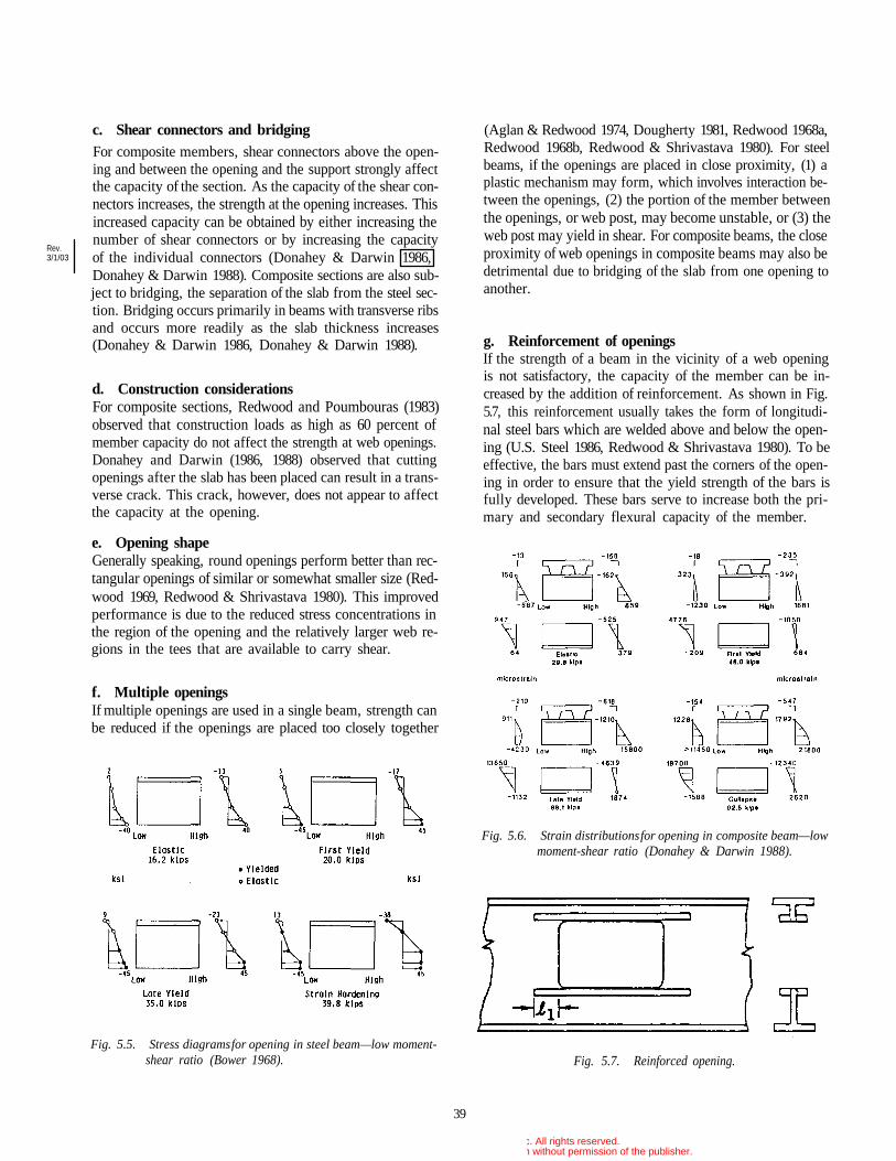
c. Shear connectors and bridgingFor composite members, shear connectors above the open-ing and between the opening and the support strongly affectthe capacity of the section. As the capacity of the shear con-nectors increases, the strength at the opening increases. Thisincreased capacity can be obtained by either increasing thenumber of shear connectors or by increasing the capacityof the individual connectors (Donahey & Darwin 1986,Donahey & Darwin 1988). Composite sections are also sub-ject to bridging, the separation of the slab from the steel sec-tion. Bridging occurs primarily in beams with transverse ribsand occurs more readily as the slab thickness increases(Donahey & Darwin 1986, Donahey & Darwin 1988).
d. Construction considerationsFor composite sections, Redwood and Poumbouras (1983)observed that construction loads as high as 60 percent ofmember capacity do not affect the strength at web openings.Donahey and Darwin (1986, 1988) observed that cuttingopenings after the slab has been placed can result in a trans-verse crack. This crack, however, does not appear to affectthe capacity at the opening.
e. Opening shapeGenerally speaking, round openings perform better than rec-tangular openings of similar or somewhat smaller size (Red-wood 1969, Redwood & Shrivastava 1980). This improvedperformance is due to the reduced stress concentrations inthe region of the opening and the relatively larger web re-gions in the tees that are available to carry shear.
f. Multiple openingsIf multiple openings are used in a single beam, strength canbe reduced if the openings are placed too closely together
Fig. 5.5. Stress diagrams for opening in steel beam—low moment-shear ratio (Bower 1968).
(Aglan & Redwood 1974, Dougherty 1981, Redwood 1968a,Redwood 1968b, Redwood & Shrivastava 1980). For steelbeams, if the openings are placed in close proximity, (1) aplastic mechanism may form, which involves interaction be-tween the openings, (2) the portion of the member betweenthe openings, or web post, may become unstable, or (3) theweb post may yield in shear. For composite beams, the closeproximity of web openings in composite beams may also bedetrimental due to bridging of the slab from one opening toanother.
g. Reinforcement of openingsIf the strength of a beam in the vicinity of a web openingis not satisfactory, the capacity of the member can be in-creased by the addition of reinforcement. As shown in Fig.5.7, this reinforcement usually takes the form of longitudi-nal steel bars which are welded above and below the open-ing (U.S. Steel 1986, Redwood & Shrivastava 1980). To beeffective, the bars must extend past the corners of the open-ing in order to ensure that the yield strength of the bars isfully developed. These bars serve to increase both the pri-mary and secondary flexural capacity of the member.
Fig. 5.6. Strain distributions for opening in composite beam—lowmoment-shear ratio (Donahey & Darwin 1988).
Fig. 5.7. Reinforced opening.
39
Rev.3/1/03
© 2003 by American Institute of Steel Construction, Inc. All rights reserved.This publication or any part thereof must not be reproduced in any form without permission of the publisher.
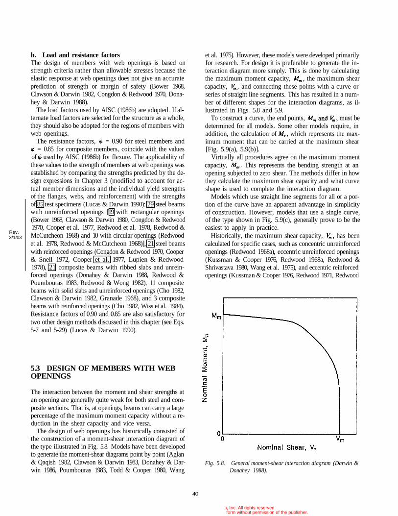
h. Load and resistance factorsThe design of members with web openings is based onstrength criteria rather than allowable stresses because theelastic response at web openings does not give an accurateprediction of strength or margin of safety (Bower 1968,Clawson & Darwin 1982, Congdon & Redwood 1970, Dona-hey & Darwin 1988).
The load factors used by AISC (1986b) are adopted. If al-ternate load factors are selected for the structure as a whole,they should also be adopted for the regions of members withweb openings.
The resistance factors, = 0.90 for steel members and= 0.85 for composite members, coincide with the values
of used by AISC (1986b) for flexure. The applicability ofthese values to the strength of members at web openings wasestablished by comparing the strengths predicted by the de-sign expressions in Chapter 3 (modified to account for ac-tual member dimensions and the individual yield strengthsof the flanges, webs, and reinforcement) with the strengthsof 85 test specimens (Lucas & Darwin 1990): 29 steel beamswith unreinforced openings [19 with rectangular openings(Bower 1968, Clawson & Darwin 1980, Congdon & Redwood1970, Cooper et al. 1977, Redwood et al. 1978, Redwood &McCutcheon 1968) and 10 with circular openings (Redwoodet al. 1978, Redwood & McCutcheon 1968)], 21 steel beamswith reinforced openings (Congdon & Redwood 1970, Cooper& Snell 1972, Cooper et al. 1977, Lupien & Redwood1978), 21 composite beams with ribbed slabs and unrein-forced openings (Donahey & Darwin 1988, Redwood &Poumbouras 1983, Redwood & Wong 1982), 11 compositebeams with solid slabs and unreinforced openings (Cho 1982,Clawson & Darwin 1982, Granade 1968), and 3 compositebeams with reinforced openings (Cho 1982, Wiss et al. 1984).Resistance factors of 0.90 and 0.85 are also satisfactory fortwo other design methods discussed in this chapter (see Eqs.5-7 and 5-29) (Lucas & Darwin 1990).
5.3 DESIGN OF MEMBERS WITH WEBOPENINGS
The interaction between the moment and shear strengths atan opening are generally quite weak for both steel and com-posite sections. That is, at openings, beams can carry a largepercentage of the maximum moment capacity without a re-duction in the shear capacity and vice versa.
The design of web openings has historically consisted ofthe construction of a moment-shear interaction diagram ofthe type illustrated in Fig. 5.8. Models have been developedto generate the moment-shear diagrams point by point (Aglan& Qaqish 1982, Clawson & Darwin 1983, Donahey & Dar-win 1986, Poumbouras 1983, Todd & Cooper 1980, Wang
et al. 1975). However, these models were developed primarilyfor research. For design it is preferable to generate the in-teraction diagram more simply. This is done by calculatingthe maximum moment capacity, the maximum shearcapacity, and connecting these points with a curve orseries of straight line segments. This has resulted in a num-ber of different shapes for the interaction diagrams, as il-lustrated in Figs. 5.8 and 5.9.
To construct a curve, the end points, must bedetermined for all models. Some other models require, inaddition, the calculation of which represents the max-imum moment that can be carried at the maximum shear[Fig. 5.9(a), 5.9(b)].
Virtually all procedures agree on the maximum momentcapacity, This represents the bending strength at anopening subjected to zero shear. The methods differ in howthey calculate the maximum shear capacity and what curveshape is used to complete the interaction diagram.
Models which use straight line segments for all or a por-tion of the curve have an apparent advantage in simplicityof construction. However, models that use a single curve,of the type shown in Fig. 5.9(c), generally prove to be theeasiest to apply in practice.
Historically, the maximum shear capacity, has beencalculated for specific cases, such as concentric unreinforcedopenings (Redwood 1968a), eccentric unreinforced openings(Kussman & Cooper 1976, Redwood 1968a, Redwood &Shrivastava 1980, Wang et al. 1975), and eccentric reinforcedopenings (Kussman & Cooper 1976, Redwood 1971, Redwood
Fig. 5.8. General moment-shear interaction diagram (Darwin &Donahey 1988).
40
Rev.3/1/03
© 2003 by American Institute of Steel Construction, Inc. All rights reserved.This publication or any part thereof must not be reproduced in any form without permission of the publisher.
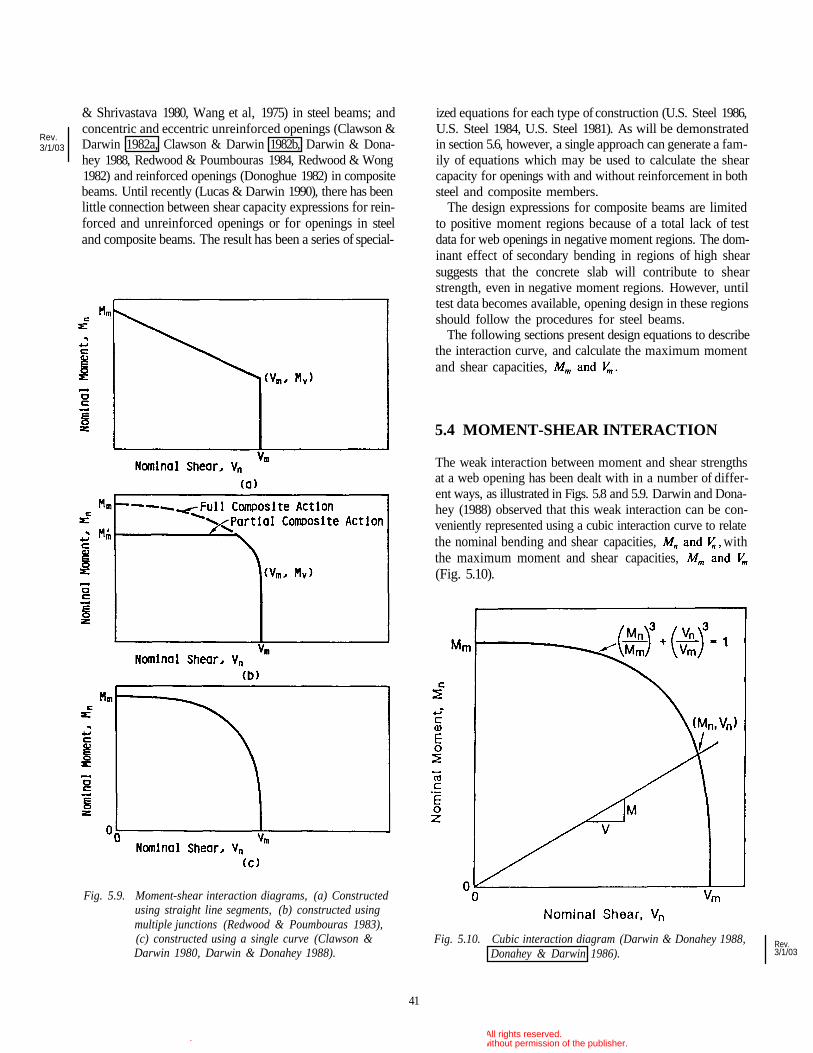
& Shrivastava 1980, Wang et al, 1975) in steel beams; andconcentric and eccentric unreinforced openings (Clawson &Darwin 1982a, Clawson & Darwin 1982b, Darwin & Dona-hey 1988, Redwood & Poumbouras 1984, Redwood & Wong1982) and reinforced openings (Donoghue 1982) in compositebeams. Until recently (Lucas & Darwin 1990), there has beenlittle connection between shear capacity expressions for rein-forced and unreinforced openings or for openings in steeland composite beams. The result has been a series of special-
Fig. 5.9. Moment-shear interaction diagrams, (a) Constructedusing straight line segments, (b) constructed usingmultiple junctions (Redwood & Poumbouras 1983),(c) constructed using a single curve (Clawson &Darwin 1980, Darwin & Donahey 1988).
ized equations for each type of construction (U.S. Steel 1986,U.S. Steel 1984, U.S. Steel 1981). As will be demonstratedin section 5.6, however, a single approach can generate a fam-ily of equations which may be used to calculate the shearcapacity for openings with and without reinforcement in bothsteel and composite members.
The design expressions for composite beams are limitedto positive moment regions because of a total lack of testdata for web openings in negative moment regions. The dom-inant effect of secondary bending in regions of high shearsuggests that the concrete slab will contribute to shearstrength, even in negative moment regions. However, untiltest data becomes available, opening design in these regionsshould follow the procedures for steel beams.
The following sections present design equations to describethe interaction curve, and calculate the maximum momentand shear capacities,
5.4 MOMENT-SHEAR INTERACTION
The weak interaction between moment and shear strengthsat a web opening has been dealt with in a number of differ-ent ways, as illustrated in Figs. 5.8 and 5.9. Darwin and Dona-hey (1988) observed that this weak interaction can be con-veniently represented using a cubic interaction curve to relatethe nominal bending and shear capacities, withthe maximum moment and shear capacities,(Fig. 5.10).
Fig. 5.10. Cubic interaction diagram (Darwin & Donahey 1988,Donahey & Darwin 1986).
41
Rev.3/1/03
Rev.3/1/03
© 2003 by American Institute of Steel Construction, Inc. All rights reserved.This publication or any part thereof must not be reproduced in any form without permission of the publisher.
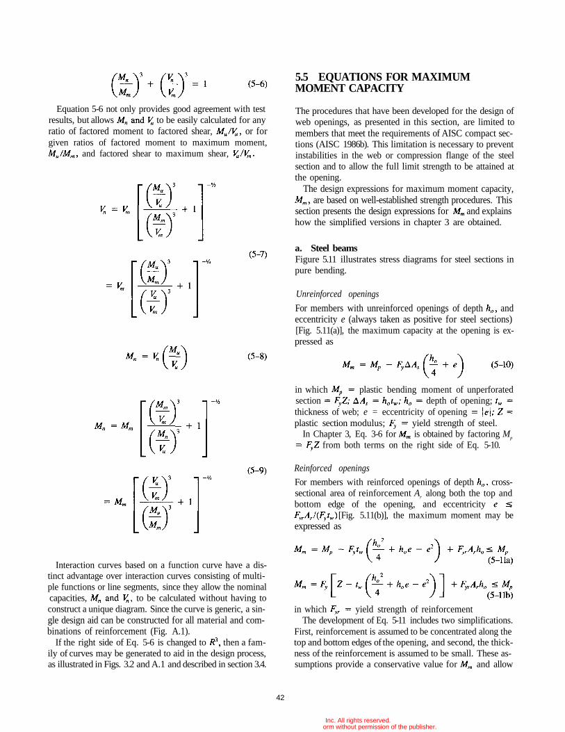
Equation 5-6 not only provides good agreement with testresults, but allows to be easily calculated for anyratio of factored moment to factored shear, or forgiven ratios of factored moment to maximum moment,
and factored shear to maximum shear,
Interaction curves based on a function curve have a dis-tinct advantage over interaction curves consisting of multi-ple functions or line segments, since they allow the nominalcapacities, to be calculated without having toconstruct a unique diagram. Since the curve is generic, a sin-gle design aid can be constructed for all material and com-binations of reinforcement (Fig. A.1).
If the right side of Eq. 5-6 is changed to then a fam-ily of curves may be generated to aid in the design process,as illustrated in Figs. 3.2 and A.1 and described in section 3.4.
5.5 EQUATIONS FOR MAXIMUMMOMENT CAPACITY
The procedures that have been developed for the design ofweb openings, as presented in this section, are limited tomembers that meet the requirements of AISC compact sec-tions (AISC 1986b). This limitation is necessary to preventinstabilities in the web or compression flange of the steelsection and to allow the full limit strength to be attained atthe opening.
The design expressions for maximum moment capacity,are based on well-established strength procedures. This
section presents the design expressions for and explainshow the simplified versions in chapter 3 are obtained.
a. Steel beamsFigure 5.11 illustrates stress diagrams for steel sections inpure bending.
Unreinforced openings
For members with unreinforced openings of depth andeccentricity e (always taken as positive for steel sections)[Fig. 5.11(a)], the maximum capacity at the opening is ex-pressed as
in which plastic bending moment of unperforatedsection depth of opening;thickness of web; e = eccentricity of openingplastic section modulus; yield strength of steel.
In Chapter 3, Eq. 3-6 for is obtained by factoring Mp
from both terms on the right side of Eq. 5-10.
Reinforced openings
For members with reinforced openings of depth cross-sectional area of reinforcement Ar along both the top andbottom edge of the opening, and eccentricity
[Fig. 5.11(b)], the maximum moment may beexpressed as
in which yield strength of reinforcementThe development of Eq. 5-11 includes two simplifications.
First, reinforcement is assumed to be concentrated along thetop and bottom edges of the opening, and second, the thick-ness of the reinforcement is assumed to be small. These as-sumptions provide a conservative value for and allow
42
© 2003 by American Institute of Steel Construction, Inc. All rights reserved.This publication or any part thereof must not be reproduced in any form without permission of the publisher.
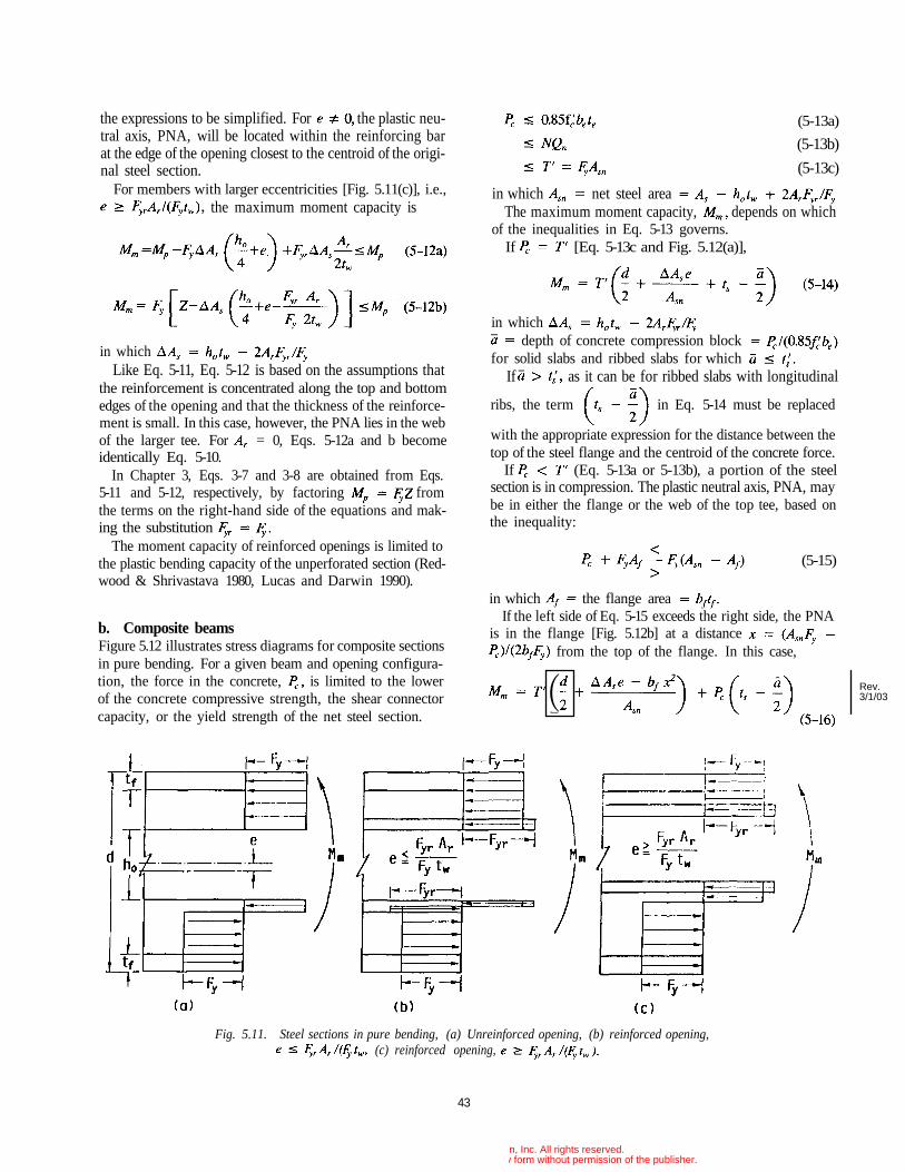
the expressions to be simplified. For the plastic neu-tral axis, PNA, will be located within the reinforcing barat the edge of the opening closest to the centroid of the origi-nal steel section.
For members with larger eccentricities [Fig. 5.11(c)], i.e.,the maximum moment capacity is
in whichLike Eq. 5-11, Eq. 5-12 is based on the assumptions that
the reinforcement is concentrated along the top and bottomedges of the opening and that the thickness of the reinforce-ment is small. In this case, however, the PNA lies in the webof the larger tee. For = 0, Eqs. 5-12a and b becomeidentically Eq. 5-10.
In Chapter 3, Eqs. 3-7 and 3-8 are obtained from Eqs.5-11 and 5-12, respectively, by factoring fromthe terms on the right-hand side of the equations and mak-ing the substitution
The moment capacity of reinforced openings is limited tothe plastic bending capacity of the unperforated section (Red-wood & Shrivastava 1980, Lucas and Darwin 1990).
b. Composite beamsFigure 5.12 illustrates stress diagrams for composite sectionsin pure bending. For a given beam and opening configura-tion, the force in the concrete, is limited to the lowerof the concrete compressive strength, the shear connectorcapacity, or the yield strength of the net steel section.
(5-13a)
(5-13b)
(5-13c)
in which net steel areaThe maximum moment capacity, depends on which
of the inequalities in Eq. 5-13 governs.If [Eq. 5-13c and Fig. 5.12(a)],
in whichdepth of concrete compression block
for solid slabs and ribbed slabs for whichIf as it can be for ribbed slabs with longitudinal
ribs, the term in Eq. 5-14 must be replaced
with the appropriate expression for the distance between thetop of the steel flange and the centroid of the concrete force.
If (Eq. 5-13a or 5-13b), a portion of the steelsection is in compression. The plastic neutral axis, PNA, maybe in either the flange or the web of the top tee, based onthe inequality:
(5-15)
in which the flange areaIf the left side of Eq. 5-15 exceeds the right side, the PNA
is in the flange [Fig. 5.12b] at a distancefrom the top of the flange. In this case,
43
Fig. 5.11. Steel sections in pure bending, (a) Unreinforced opening, (b) reinforced opening,(c) reinforced opening,
Rev.3/1/03
© 2003 by American Institute of Steel Construction, Inc. All rights reserved.This publication or any part thereof must not be reproduced in any form without permission of the publisher.
(
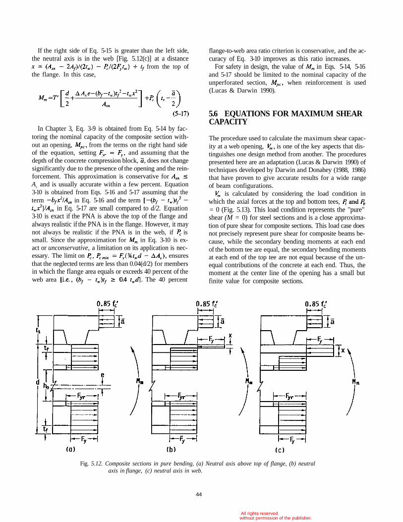
flange-to-web area ratio criterion is conservative, and the ac-curacy of Eq. 3-10 improves as this ratio increases.
For safety in design, the value of in Eqs. 5-14, 5-16and 5-17 should be limited to the nominal capacity of theunperforated section, when reinforcement is used(Lucas & Darwin 1990).
5.6 EQUATIONS FOR MAXIMUM SHEARCAPACITY
The procedure used to calculate the maximum shear capac-ity at a web opening, is one of the key aspects that dis-tinguishes one design method from another. The procedurespresented here are an adaptation (Lucas & Darwin 1990) oftechniques developed by Darwin and Donahey (1988, 1986)that have proven to give accurate results for a wide rangeof beam configurations.
is calculated by considering the load condition inwhich the axial forces at the top and bottom tees,= 0 (Fig. 5.13). This load condition represents the "pure"shear (M = 0) for steel sections and is a close approxima-tion of pure shear for composite sections. This load case doesnot precisely represent pure shear for composite beams be-cause, while the secondary bending moments at each endof the bottom tee are equal, the secondary bending momentsat each end of the top tee are not equal because of the un-equal contributions of the concrete at each end. Thus, themoment at the center line of the opening has a small butfinite value for composite sections.
Fig. 5.12. Composite sections in pure bending, (a) Neutral axis above top of flange, (b) neutralaxis in flange, (c) neutral axis in web.
44
If the right side of Eq. 5-15 is greater than the left side,the neutral axis is in the web [Fig. 5.12(c)] at a distance
from the top ofthe flange. In this case,
In Chapter 3, Eq. 3-9 is obtained from Eq. 5-14 by fac-toring the nominal capacity of the composite section with-out an opening, from the terms on the right hand sideof the equation, setting and assuming that thedepth of the concrete compression block, does not changesignificantly due to the presence of the opening and the rein-forcement. This approximation is conservative forAs and is usually accurate within a few percent. Equation3-10 is obtained from Eqs. 5-16 and 5-17 assuming that theterm in Eq. 5-16 and the term
in Eq. 5-17 are small compared to d/2. Equation3-10 is exact if the PNA is above the top of the flange andalways realistic if the PNA is in the flange. However, it maynot always be realistic if the PNA is in the web, if issmall. Since the approximation for in Eq. 3-10 is ex-act or unconservative, a limitation on its application is nec-essary. The limit on ensuresthat the neglected terms are less than 0.04(d/2) for membersin which the flange area equals or exceeds 40 percent of theweb area The 40 percent
© 2003 by American Institute of Steel Construction, Inc. All rights reserved.This publication or any part thereof must not be reproduced in any form without permission of the publisher.
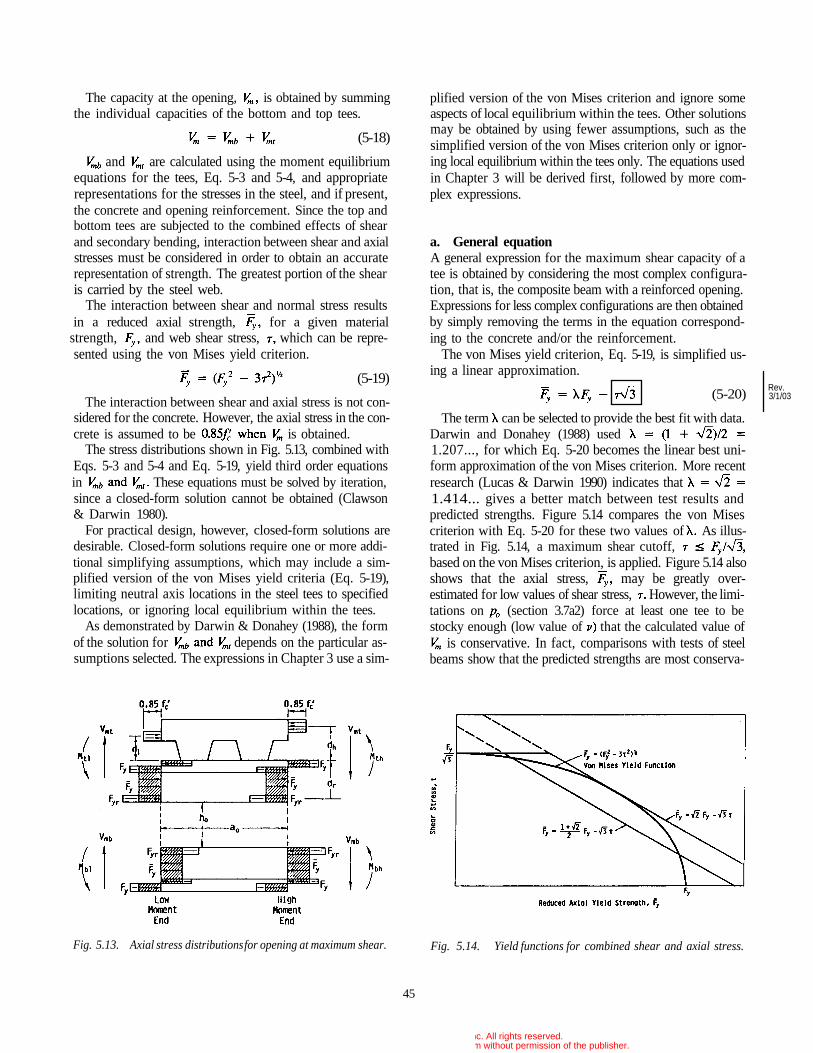
The capacity at the opening, is obtained by summingthe individual capacities of the bottom and top tees.
(5-18)
and are calculated using the moment equilibriumequations for the tees, Eq. 5-3 and 5-4, and appropriaterepresentations for the stresses in the steel, and if present,the concrete and opening reinforcement. Since the top andbottom tees are subjected to the combined effects of shearand secondary bending, interaction between shear and axialstresses must be considered in order to obtain an accuraterepresentation of strength. The greatest portion of the shearis carried by the steel web.
The interaction between shear and normal stress resultsin a reduced axial strength, for a given material
strength, and web shear stress, which can be repre-sented using the von Mises yield criterion.
(5-19)
The interaction between shear and axial stress is not con-sidered for the concrete. However, the axial stress in the con-crete is assumed to be is obtained.
The stress distributions shown in Fig. 5.13, combined withEqs. 5-3 and 5-4 and Eq. 5-19, yield third order equationsin These equations must be solved by iteration,since a closed-form solution cannot be obtained (Clawson& Darwin 1980).
For practical design, however, closed-form solutions aredesirable. Closed-form solutions require one or more addi-tional simplifying assumptions, which may include a sim-plified version of the von Mises yield criteria (Eq. 5-19),limiting neutral axis locations in the steel tees to specifiedlocations, or ignoring local equilibrium within the tees.
As demonstrated by Darwin & Donahey (1988), the formof the solution for depends on the particular as-sumptions selected. The expressions in Chapter 3 use a sim-
plified version of the von Mises criterion and ignore someaspects of local equilibrium within the tees. Other solutionsmay be obtained by using fewer assumptions, such as thesimplified version of the von Mises criterion only or ignor-ing local equilibrium within the tees only. The equations usedin Chapter 3 will be derived first, followed by more com-plex expressions.
a. General equationA general expression for the maximum shear capacity of atee is obtained by considering the most complex configura-tion, that is, the composite beam with a reinforced opening.Expressions for less complex configurations are then obtainedby simply removing the terms in the equation correspond-ing to the concrete and/or the reinforcement.
The von Mises yield criterion, Eq. 5-19, is simplified us-ing a linear approximation.
(5-20)
The term can be selected to provide the best fit with data.Darwin and Donahey (1988) used1.207..., for which Eq. 5-20 becomes the linear best uni-form approximation of the von Mises criterion. More recentresearch (Lucas & Darwin 1990) indicates that1.414... gives a better match between test results andpredicted strengths. Figure 5.14 compares the von Misescriterion with Eq. 5-20 for these two values of As illus-trated in Fig. 5.14, a maximum shear cutoff,based on the von Mises criterion, is applied. Figure 5.14 alsoshows that the axial stress, may be greatly over-estimated for low values of shear stress, However, the limi-tations on (section 3.7a2) force at least one tee to bestocky enough (low value of that the calculated value of
is conservative. In fact, comparisons with tests of steelbeams show that the predicted strengths are most conserva-
Fig. 5.13. Axial stress distributions for opening at maximum shear. Fig. 5.14. Yield functions for combined shear and axial stress.
45
Rev.3/1/03
© 2003 by American Institute of Steel Construction, Inc. All rights reserved.This publication or any part thereof must not be reproduced in any form without permission of the publisher.
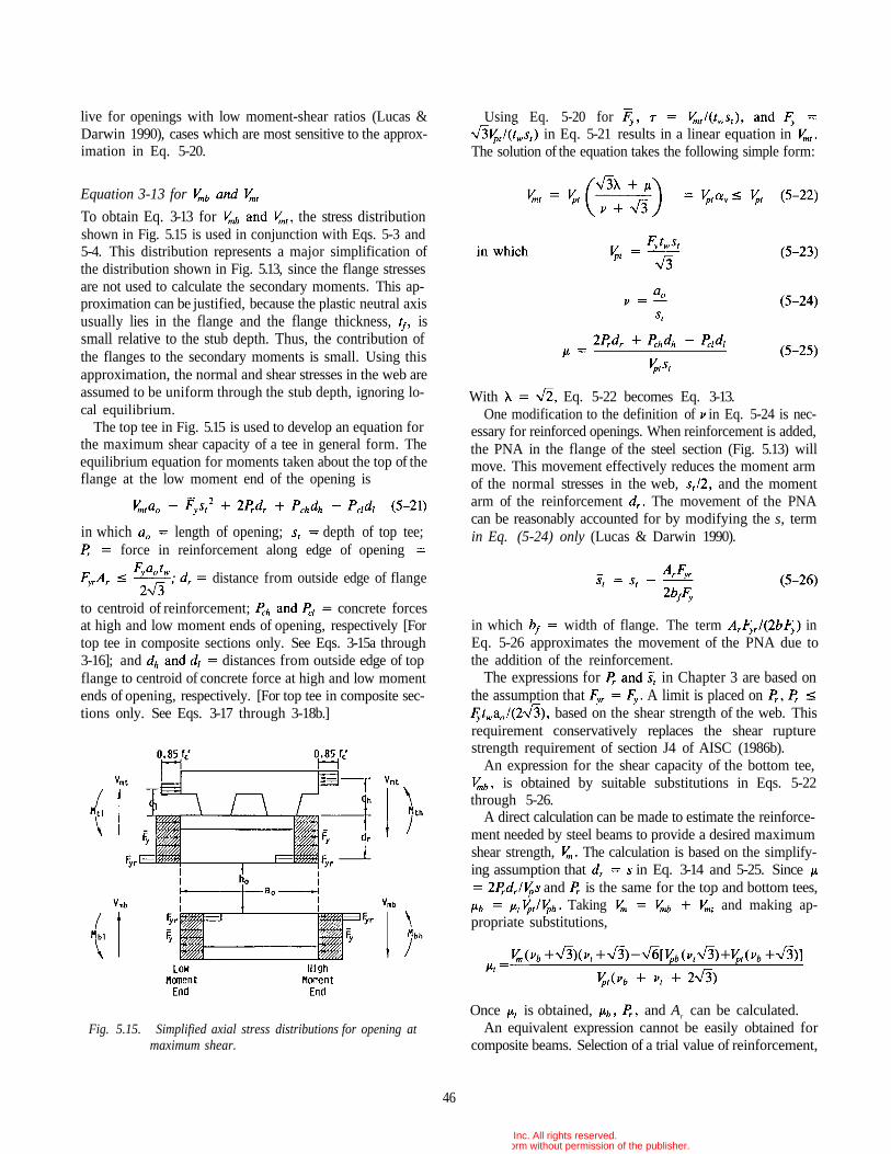
live for openings with low moment-shear ratios (Lucas &Darwin 1990), cases which are most sensitive to the approx-imation in Eq. 5-20.
Equation 3-13 for
To obtain Eq. 3-13 for the stress distributionshown in Fig. 5.15 is used in conjunction with Eqs. 5-3 and5-4. This distribution represents a major simplification ofthe distribution shown in Fig. 5.13, since the flange stressesare not used to calculate the secondary moments. This ap-proximation can be justified, because the plastic neutral axisusually lies in the flange and the flange thickness, issmall relative to the stub depth. Thus, the contribution ofthe flanges to the secondary moments is small. Using thisapproximation, the normal and shear stresses in the web areassumed to be uniform through the stub depth, ignoring lo-cal equilibrium.
The top tee in Fig. 5.15 is used to develop an equation forthe maximum shear capacity of a tee in general form. Theequilibrium equation for moments taken about the top of theflange at the low moment end of the opening is
in which length of opening; depth of top tee;force in reinforcement along edge of opening
distance from outside edge of flange
to centroid of reinforcement; concrete forcesat high and low moment ends of opening, respectively [Fortop tee in composite sections only. See Eqs. 3-15a through3-16]; and distances from outside edge of topflange to centroid of concrete force at high and low momentends of opening, respectively. [For top tee in composite sec-tions only. See Eqs. 3-17 through 3-18b.]
Fig. 5.15. Simplified axial stress distributions for opening atmaximum shear.
Using Eq. 5-20 forin Eq. 5-21 results in a linear equation in
The solution of the equation takes the following simple form:
With Eq. 5-22 becomes Eq. 3-13.One modification to the definition of in Eq. 5-24 is nec-
essary for reinforced openings. When reinforcement is added,the PNA in the flange of the steel section (Fig. 5.13) willmove. This movement effectively reduces the moment armof the normal stresses in the web, and the momentarm of the reinforcement The movement of the PNAcan be reasonably accounted for by modifying the s, termin Eq. (5-24) only (Lucas & Darwin 1990).
in which width of flange. The term inEq. 5-26 approximates the movement of the PNA due tothe addition of the reinforcement.
The expressions for in Chapter 3 are based onthe assumption that A limit is placed on
based on the shear strength of the web. Thisrequirement conservatively replaces the shear rupturestrength requirement of section J4 of AISC (1986b).
An expression for the shear capacity of the bottom tee,is obtained by suitable substitutions in Eqs. 5-22
through 5-26.A direct calculation can be made to estimate the reinforce-
ment needed by steel beams to provide a desired maximumshear strength, The calculation is based on the simplify-ing assumption that in Eq. 3-14 and 5-25. Since
and is the same for the top and bottom tees,Taking and making ap-
propriate substitutions,
Once is obtained, and Ar can be calculated.An equivalent expression cannot be easily obtained for
composite beams. Selection of a trial value of reinforcement,
46
© 2003 by American Institute of Steel Construction, Inc. All rights reserved.This publication or any part thereof must not be reproduced in any form without permission of the publisher.
however, provides a straightforward solution for both steeland composite beams, as illustrated in Examples 2 and 4 inChapter 3.
Alternate equations for
If the full von Mises criterion (Eq. 5-19) is used, insteadof the linear approximation (Eq. 5-20), to represent inEq. 5-21, a quadratic equation is obtained for The so-lution of that equation takes a somewhat more complex formthan Eq. 5-21.
(5-27)
in which are as previously defined. For non-composite tees without reinforcement, Eq. 5-27 takes a sim-pler form.
(5-28)
Equations 5-27 and 5-28 are identical with those used byRedwood and Poumbouras (1984) and by Darwin and Dona-hey (1988) in their "Solution II." These equations completelysatisfy the von Mises criterion, but, perhaps surprisingly, donot provide a closer match with experimental data than Eq.5-22 (Lucas & Darwin 1990).
To obtain a better match with experimental results requiresanother approach (Darwin & Donahey 1988, Lucas & Dar-win 1990). This approach uses the linear approximation forthe von Mises criterion (Eq. 5-19) to control the interactionbetween shear and normal stresses within the web of the steeltee, but uses a stress distribution based on the full cross-section of the steel tee (Fig. 5.13) to develop the secondarymoment equilibrium equation (Eq. 5-4). The PNA is as-sumed to fall in the flange of the steel tee; its precise loca-tion is accounted for in the solution for
is expressed as follows:
Equation 5-29 is clearly more complex than Eqs. 5-22and 5-27 and is best suited for use with a programmable cal-culator or computer. It has the advantages that it accountsfor the actual steel section and does not require a separatecalculation for when reinforcement is used. WithEq. 5-29 produces a closer match with the experimental datathan the other two options (Lucas & Darwin 1990). How-ever, since the flange is included in the calculations, Eq. 5-29cannot be used to produce a general design aid.
Expressions for tees without concrete and/or opening rein-forcement can be obtained from Eqs. 5-29 by settingand to zero, as required.
b. Composite beamsAs explained in Chapter 3, a number of additional expres-sions are required to calculate the shear capacity of the toptee in composite beams.
The forces in the concrete at the high and low momentends of the opening, and the distances to theseforces from the top of the flange of the steel section, anddh are calculated using Eqs. 3-15a through 3-18b. islimited by the force in the concrete, based on an averagestress of the stud capacity between thehigh moment end of the opening and the support andthe tensile capacity of the top tee steel section, Thethird limitation was not originally used in conjunc-tion with Eqs. 5-22 and 5-27, because it was felt to be in-consistent with a model (Fig. 5-15) that ignored the flangeof the steel tee (Darwin & Donahey 1988, Donahey & Dar-win 1986). Lucas and Darwin (1990), however, have shownthat generally improved solutions are obtained when all theselimitations are used in conjunction with Eqs. 5-22 and 5-27,as well as Eq. 5-29 which considers the flange.
The number of studs, N, used for the calculation ofincludes the studs between the high moment end of the open-ing and the support, not the point of zero moment. Thischange from normal practice takes into account the largeamount of slip that occurs between the slab and the steelsection at openings, which tends to mobilize stud capacity,even studs in negative moment regions (Darwin & Donahey1988, Donahey & Darwin 1986, Donahey & Darwin 1988).To use the more conservative approach will greatly under-estimate the shear capacity of openings placed at a point ofcontraflexure (Donahey & Darwin 1986).
47
in which
Rev.3/1/03
) Rev.3/1/03
© 2003 by American Institute of Steel Construction, Inc. All rights reserved.This publication or any part thereof must not be reproduced in any form without permission of the publisher.
l
The difference between (Eq. 3-16) is equal tothe shear connector capacity over the opening,
Equations 5-22, 5-27, and 5-29 are based on the assump-tion that all of the shear carried by a tee is carried by thesteel web. This assumption yields consistent results for steeltees, but may be overconservative for top tees in compositebeams, since the concrete slab may also carry shear. Ifin these expressions exceeds the web is fully yielded inshear . Equilibrium requires that is limited tothe axial strength of the flange and the reinforcement in thetop tee, as given by Eq. 3-20,in which thickness of flange. This limit on replacesEq. 3-15c.
Resolving Eq. 5-21 yields
Equation 5-30b is equivalent to Eq. 3-19. Since iscorrectly defined by Eq. 5-30a, in Eq. 5-30bis calculated based on s for reinforced openings.
If the flange of the top tee is included in the equilibriumequation once the solution for yields
The value of calculated with Eq. 5-31 slightly exceedsthe value obtained with Eq. 5-30. Equation 5-31 has beenused in conjunction with Eq. 5-29, while Eq. 5-30 has beenused with Eqs. 5-22 and 5-27 (Cho & Redwood 1986, Darwin& Donahey 1988, Donahey & Darwin 1986, AISC 1986b).
An upper limit is placed on in Eq. 3-21, based on themaximum combined capacity of the steel web and the con-crete slab in pure shear.
The contribution of the concrete to the maximum shearcapacity of the top tee in Eq. 3-21, 0.11 was origi-nally estimated for solid slabs, based on the shear behaviorof reinforced concrete beams and slabs (Clawson & Darwin1980, Clawson & Darwin 1983), and later modified forribbed slabs (Darwin & Donahey 1988, Donahey & Darwin1986). Equation 3-21 generally governs only for beamswith short openings, usually
c. Design aidsThe design aids presented in Appendix A, Figs. A.2 and A.3,represent as a function of
or for values of ranging from 0 to 23.
The upper limit of in Fig. A.3 is se-lected for convenience and clarity of the diagram. Only twobeams in all of the tests exceeded this value (Lucas & Dar-win 1990). For most practical cases, will be less than 2.
The upper limit of coincides with the maximumvalue used in tests of members subjected to shear (Lucas &Darwin 1990).
5.7 GUIDELINES FOR PROPORTIONINGAND DETAILING BEAMS WITH WEBOPENINGS
The guidelines presented in section 3.7 are based on boththeoretical considerations and experimental observations.Many of the guidelines were originally developed for non-composite beams (Redwood & Shrivastava 1980, ASCE 1973)and are adopted as appropriate for composite members. Theguidelines are meant to help ensure that the limit statespredicted by the design equations are obtained. For this rea-son, steel sections should meet the AISC requirements forcompact sections (AISC 1986b). Yield strength, islimited to 65 ksi since plastic design is the basis for the de-sign expressions. The other provisions of the AISC LRFDSpecifications (AISC 1986b) should apply to these membersas well.
a. Stability considerations
1. Local buckling of compression flange orreinforcement
To prevent local buckling of the compression flange or rein-forcement at an opening, the AISC (1986b) criteria for com-pact sections is applied to the reinforcement as well as thesteel section (Eq. 3-22).
2. Web buckling
The criteria to prevent web buckling are based on the workof Redwood and Uenoya (1979) in which they developed con-servative criteria based on the opening size and shape andthe slenderness of the web of the member. The recommen-dations are based on both experimental (Redwood et al. 1978)and analytical work (Redwood & Uenoya 1979, Uenoya &Redwood 1978). The experimental work included openingswith depths or diameters ranging from 0.34d to 0.63d andopening length-to-depth ratios of 1 and 2. The analysescovered openings with depths and opening length-to-depth ratios ranging from 1 to 2.
Their recommendations are adopted in whole for steelmembers and relaxed slightly for composite sections to ac-count for the portion of the shear carried by the concreteslab, The higher limit on the opening parameter, of6.0 for composite sections versus 5.6 for steel sections coin-
48
© 2003 by American Institute of Steel Construction, Inc. All rights reserved.This publication or any part thereof must not be reproduced in any form without permission of the publisher.
cides with successful tests (Donahey & Darwin 1988). Fail-ure in composite sections is normally governed by failureof the concrete slab, and adequate strength has been obtainedeven when local buckling has been observed (Clawson & Dar-win 1980, Clawson & Darwin 1982, Donahey & Darwin1986). As discussed in section 5.6 (after Eq. 5-20), the limitson also serve to ensure that the design equations provideconservative predictions for member shear strength, even ifweb buckling is not a factor.
Limits on based on the web width-thickness ratio areused for both steel and composite sections. Somewhat morelenient criteria are applied to the composite sections. How-ever, no detailed theoretical analyses have been made. Theguidelines limiting the maximum values of can be quiteconservative for sections with web width-thickness ratios be-low the maximum limits. Redwood & Uenoya (1979) pro-vide guidance for members which lie outside the limits ofthis section.
3. Buckling of tee-shaped compression zone
For noncomposite members, a check must be made to en-sure that buckling of the tee-shaped compression zone aboveor below an opening does not occur. This is of concernprimarily for large openings in regions of high moment (Red-wood & Shrivastava 1980). This need not be considered forcomposite members subject to positive bending.
4. Lateral buckling
The guidelines for openings in members subject to lateralbuckling closely follow the recommendations of Redwoodand Shrivastava (1980). They point out that openings havelittle effect on the lateral stability of W-shaped sections. How-ever, design expressions have not been formulated to pre-dict the inelastic lateral buckling capacity for a member withan opening, and to be safe, member strength should begoverned by a point remote from the opening (Redwood &Shrivastava 1980).
Equation 3-26 is an extension of recommendations madeby Redwood & Shrivastava (1980) and ASCE (1973) for usewith the lateral buckling provisions of design specifications(AISC 1986b). Redwood and Shrivastava recommend the ap-plication of Eq. 3-26 only if the value of this expression isless than 0.90.
The increased load on the lateral bracing for unsymmetri-cally reinforced members is also recommended by Lupienand Redwood (1978).
b. Other considerations
1. Opening and tee dimensions
Opening dimensions are largely controlled by the limitationson given in section 3.7a2. The limitationsplaced on the opening and tee dimensions in section 3.7blare based on practical considerations. Opening depths in ex-
cess of 70 percent of the section depth are unrealisticallylarge. The minimum depths of the tees are based on the needto transfer some load over the opening and a lack of test datafor shallower tees. The limit of 12 on the aspect ratio of thetees is based on a lack of data for members withgreater aspect ratios.
2. Corner radii
The limitations on the corner radii of the opening are basedon research by Frost and Leffler (1971), which indicates thatcorner radii meeting these requirements will not adverselyaffect the fatigue capacity of a member. In spite of this point,openings are not recommended for members that will be sub-jected to significant high cycle-low stress or low cycle-highstress fatigue loading.
3. Concentrated loads
Concentrated loads are not allowed over the opening becausethe design expressions are based on a constant value of shearthrough the openings and do not account for the local bend-ing and shear that would be caused by a load on the top tee.A uniform load (standard roof or floor loads) will not causea significant deviation from the behavior predicted by theequations. If a concentrated load must be placed over theopening, additional analyses are required to evaluate the re-sponse of the top tee and determine its effect on the strengthof the member at the opening. The limitations on the loca-tions of concentrated loads near openings to prevent webcrippling are based on the criteria offered by Redwood &Shrivastava (1980). The requirements represent an extensionof the criteria suggested by Redwood & Shrivastava (1980).These criteria are applied to composite and noncompositemembers with and without reinforcement, although onlylimited data exists except for unreinforced openings in steelsections (Cato 1964). The requirement that openings beplaced no closer than a distance d to a support is to limitthe horizontal shear stress that must be transferred by theweb between the opening and the support.
4. Circular openings
The criteria for converting circular openings to equivalentrectangular openings for application with the design expres-sions are adopted from Redwood & Shrivastava (1980), whichis based on an investigation by Redwood (1969) into the lo-cation of plastic hinges relative to the center line of open-ings in steel members. These conversions are adopted forcomposite beams as well. The use of for bothshear and bending in members with reinforced web open-ings is due to the fact that the reinforcement is adjacent tothe opening. Treating the reinforcement as if it were adja-cent to a shallower opening would provide an unconserva-tive value for
49
© 2003 by American Institute of Steel Construction, Inc. All rights reserved.This publication or any part thereof must not be reproduced in any form without permission of the publisher.
5. Reinforcement
The requirements for reinforcement are designed to ensurethat adequate strength is provided in the regions at the endsof the opening and that the reinforcement is adequately at-tached to develop the required strength. Equation 3-31 re-quires the weld to develop a strength of withinthe length of the opening. The factor 2 is used because thereinforcement is in tension at one end of the opening andin compression at the other end when the tee is subjectedto shear (Figs. 5.13 and 5.15). Within the extensions, rein-forcement must be anchored to provide the full yield strengthof the bars, since the expressions for are based on thisassumption. This requires (1) an extension length
based on the shear strength of the web and (2)a weld capacity of (see Eq. 3-32). The limit on
allows a single size fillet weld to be used on one sideof the bar within the length of the opening and on both sidesof the bar in the extensions.
The terms in Eq. 3-31 and in Eq. 3-32 are mul-tiplied by (0.90 for steel beams and 0.85 for compositebeams) to convert these forces into equivalent factored loads.The weld is then designed to resist the factored load,with a value of 0.75 (AISC 1986b). The result is a de-sign which is consistent with AISC (1986b).
The criteria for placing the reinforcement on one side ofthe web are based on the results of research by Lupien andRedwood (1978). The criteria are designed to limit reduc-tions in strength caused by out of plane deflections causedby eccentric loading of the reinforcement. The limitationson the area of the reinforcement, in Eq. 3-33 and as-pect ratio of the opening, in Eq. 3-34 represent theextreme values tested by Lupien and Redwood. The limita-tion on the tee slenderness, in Eq. 3-35 is primarilyempirical. The limitation on in Eq. 3-36 restrictsthe use of unsymmetrical reinforcement to regions subjectto some shear. For regions subjected to pure bending or verylow shear, the out of plane deflections of the web can besevere. Under shear, the lateral deformation mode causedby the unsymmetrical reinforcement changes to allow agreater capacity to be developed. Additional guidance isgiven by Lupien & Redwood (1978) for the use of unsym-metrical reinforcement in regions of pure bending or verylow shear.
The criteria are adopted for composite as well as steelbeams.
6. Spacing of openings
Equations 3-37a through 3-38b are designed to ensure thatopenings are spaced far enough apart so that design expres-sions for individual openings may be used (Redwood &
Shrivastava 1980). Specifically, the criteria are meant to en-sure that a plastic mechanism involving interaction betweenopenings will not develop, instability of the web posts be-tween openings will not occur, and web posts between open-ings will not yield in shear.
The additional requirements for composite members inEqs. 3-39a and b are based on observations by Donahey andDarwin (1986, 1988) of slab bridging in members with sin-gle openings. The expressions are designed to limit the poten-tial problem of slab bridging between adjacent openings, al-though no composite beams with multiple openings have beentested.
c. Additional criteria for composite beams
1. Slab reinforcementSlabs tend to crack both transversely and longitudinally inthe vicinity of web openings. Additional slab reinforcementis needed in the vicinity of the openings to limit the crackwidths and improve the post-crack strength of the slab. Therecommendations are based on observations by Donahey andDarwin (1986, 1988).
2. Shear connectorsDonahey and Darwin (1986, 1988) observed significant bridg-ing (lifting of the slab from the steel section) from the lowmoment end of the opening past the high moment end ofthe opening in the direction of increasing moment. The studsin the direction of increasing moment are designed to helplimit bridging, although the studs do not enter directly intothe calculation of member strength at the opening. The mini-mum of two studs per foot is applied to the total numberof studs. If this criterion is already satisfied by normal studrequirements, additional studs are not needed.
3. Construction loads
This requirement recognizes that a composite beam with ade-quate strength at a web opening may not provide adequatecapacity during construction, when it must perform as a non-composite member.
5.8 ALLOWABLE STRESS DESIGN
The design of web openings in beams that are proportionedusing Allowable Stress Design must be based on strength be-cause the load at which yielding begins at web openings isnot a uniform measure of strength. Conservatively and forconvenience, a single load factor, 1.7, is used for dead andlive loads and a single factor, 1.00, is used for both steeland composite construction.
50
© 2003 by American Institute of Steel Construction, Inc. All rights reserved.This publication or any part thereof must not be reproduced in any form without permission of the publisher.
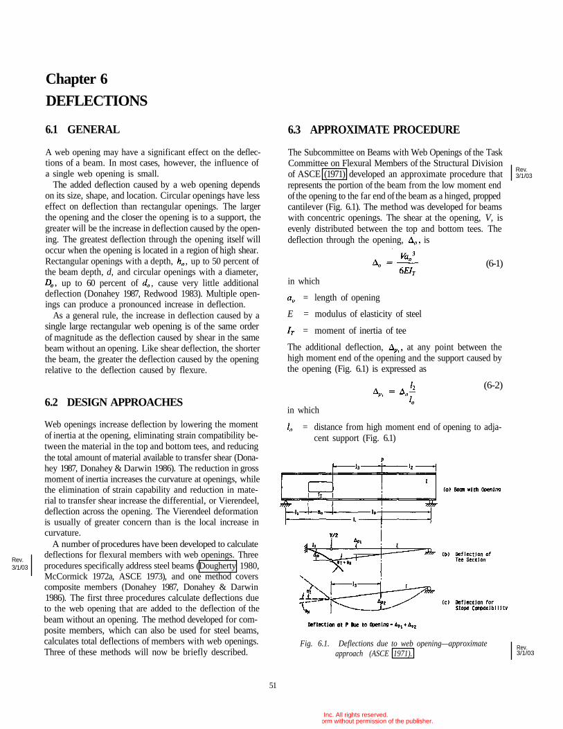
Chapter 6
DEFLECTIONS
6.1 GENERAL
A web opening may have a significant effect on the deflec-tions of a beam. In most cases, however, the influence ofa single web opening is small.
The added deflection caused by a web opening dependson its size, shape, and location. Circular openings have lesseffect on deflection than rectangular openings. The largerthe opening and the closer the opening is to a support, thegreater will be the increase in deflection caused by the open-ing. The greatest deflection through the opening itself willoccur when the opening is located in a region of high shear.Rectangular openings with a depth, , up to 50 percent ofthe beam depth, d, and circular openings with a diameter,
up to 60 percent of , cause very little additionaldeflection (Donahey 1987, Redwood 1983). Multiple open-ings can produce a pronounced increase in deflection.
As a general rule, the increase in deflection caused by asingle large rectangular web opening is of the same orderof magnitude as the deflection caused by shear in the samebeam without an opening. Like shear deflection, the shorterthe beam, the greater the deflection caused by the openingrelative to the deflection caused by flexure.
6.2 DESIGN APPROACHES
Web openings increase deflection by lowering the momentof inertia at the opening, eliminating strain compatibility be-tween the material in the top and bottom tees, and reducingthe total amount of material available to transfer shear (Dona-hey 1987, Donahey & Darwin 1986). The reduction in grossmoment of inertia increases the curvature at openings, whilethe elimination of strain capability and reduction in mate-rial to transfer shear increase the differential, or Vierendeel,deflection across the opening. The Vierendeel deformationis usually of greater concern than is the local increase incurvature.
A number of procedures have been developed to calculatedeflections for flexural members with web openings. Threeprocedures specifically address steel beams (Dougherty 1980,McCormick 1972a, ASCE 1973), and one method coverscomposite members (Donahey 1987, Donahey & Darwin1986). The first three procedures calculate deflections dueto the web opening that are added to the deflection of thebeam without an opening. The method developed for com-posite members, which can also be used for steel beams,calculates total deflections of members with web openings.Three of these methods will now be briefly described.
6.3 APPROXIMATE PROCEDURE
The Subcommittee on Beams with Web Openings of the TaskCommittee on Flexural Members of the Structural Divisionof ASCE (1971) developed an approximate procedure thatrepresents the portion of the beam from the low moment endof the opening to the far end of the beam as a hinged, proppedcantilever (Fig. 6.1). The method was developed for beamswith concentric openings. The shear at the opening, V, isevenly distributed between the top and bottom tees. Thedeflection through the opening, is
= length of opening
E = modulus of elasticity of steel
= moment of inertia of tee
The additional deflection, at any point between thehigh moment end of the opening and the support caused bythe opening (Fig. 6.1) is expressed as
(6-2)
in which
= distance from high moment end of opening to adja-cent support (Fig. 6.1)
Fig. 6.1. Deflections due to web opening—approximateapproach (ASCE 1971).
51
in which
(6-1)
Rev.3/1/03
Rev.3/1/03
Rev.3/1/03
© 2003 by American Institute of Steel Construction, Inc. All rights reserved.This publication or any part thereof must not be reproduced in any form without permission of the publisher.
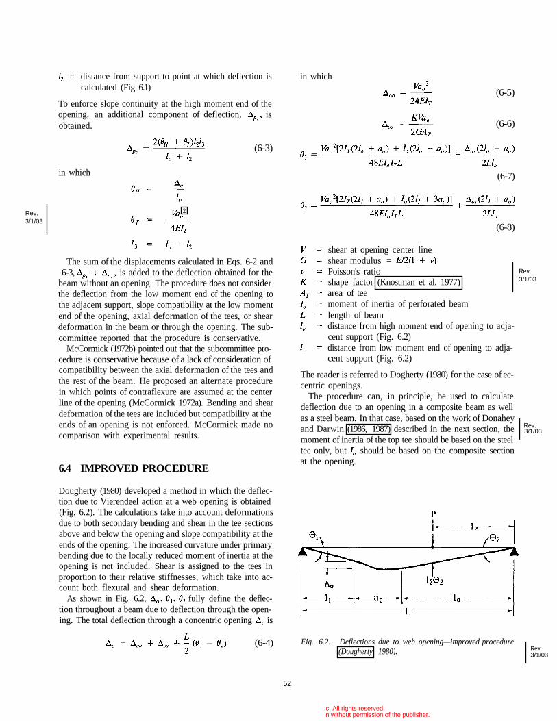
= distance from support to point at which deflection iscalculated (Fig 6.1)
To enforce slope continuity at the high moment end of theopening, an additional component of deflection, isobtained.
The sum of the displacements calculated in Eqs. 6-2 and6-3, is added to the deflection obtained for the
beam without an opening. The procedure does not considerthe deflection from the low moment end of the opening tothe adjacent support, slope compatibility at the low momentend of the opening, axial deformation of the tees, or sheardeformation in the beam or through the opening. The sub-committee reported that the procedure is conservative.
McCormick (1972b) pointed out that the subcommittee pro-cedure is conservative because of a lack of consideration ofcompatibility between the axial deformation of the tees andthe rest of the beam. He proposed an alternate procedurein which points of contraflexure are assumed at the centerline of the opening (McCormick 1972a). Bending and sheardeformation of the tees are included but compatibility at theends of an opening is not enforced. McCormick made nocomparison with experimental results.
6.4 IMPROVED PROCEDURE
shear at opening center lineshear modulus =Poisson's ratioshape factor (Knostman et al. 1977)area of teemoment of inertia of perforated beamlength of beamdistance from high moment end of opening to adja-cent support (Fig. 6.2)distance from low moment end of opening to adja-cent support (Fig. 6.2)
The reader is referred to Dogherty (1980) for the case of ec-centric openings.
The procedure can, in principle, be used to calculatedeflection due to an opening in a composite beam as wellas a steel beam. In that case, based on the work of Donaheyand Darwin (1986, 1987) described in the next section, themoment of inertia of the top tee should be based on the steeltee only, but should be based on the composite sectionat the opening.
Dougherty (1980) developed a method in which the deflec-tion due to Vierendeel action at a web opening is obtained(Fig. 6.2). The calculations take into account deformationsdue to both secondary bending and shear in the tee sectionsabove and below the opening and slope compatibility at theends of the opening. The increased curvature under primarybending due to the locally reduced moment of inertia at theopening is not included. Shear is assigned to the tees inproportion to their relative stiffnesses, which take into ac-count both flexural and shear deformation.
As shown in Fig. 6.2, fully define the deflec-tion throughout a beam due to deflection through the open-ing. The total deflection through a concentric opening is
(6-4) Fig. 6.2. Deflections due to web opening—improved procedure(Dougherty 1980).
52
(6-3)
in which
in which
(6-5)
(6-6)
(6-7)
(6-8)
Rev.3/1/03
Rev.3/1/03
Rev.3/1/03
Rev.3/1/03
© 2003 by American Institute of Steel Construction, Inc. All rights reserved.This publication or any part thereof must not be reproduced in any form without permission of the publisher.
2
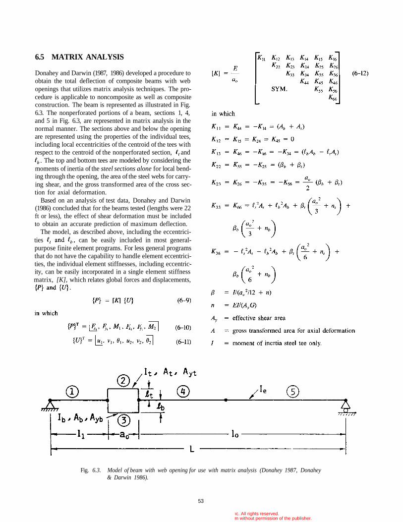
6.5 MATRIX ANALYSIS
Donahey and Darwin (1987, 1986) developed a procedure toobtain the total deflection of composite beams with webopenings that utilizes matrix analysis techniques. The pro-cedure is applicable to noncomposite as well as compositeconstruction. The beam is represented as illustrated in Fig.6.3. The nonperforated portions of a beam, sections 1, 4,and 5 in Fig. 6.3, are represented in matrix analysis in thenormal manner. The sections above and below the openingare represented using the properties of the individual tees,including local eccentricities of the centroid of the tees withrespect to the centroid of the nonperforated section, and
The top and bottom tees are modeled by considering themoments of inertia of the steel sections alone for local bend-ing through the opening, the area of the steel webs for carry-ing shear, and the gross transformed area of the cross sec-tion for axial deformation.
Based on an analysis of test data, Donahey and Darwin(1986) concluded that for the beams tested (lengths were 22ft or less), the effect of shear deformation must be includedto obtain an accurate prediction of maximum deflection.
The model, as described above, including the eccentrici-ties can be easily included in most general-purpose finite element programs. For less general programsthat do not have the capability to handle element eccentrici-ties, the individual element stiffnesses, including eccentric-ity, can be easily incorporated in a single element stiffnessmatrix, [K], which relates global forces and displacements,
Fig. 6.3. Model of beam with web opening for use with matrix analysis (Donahey 1987, Donahey& Darwin 1986).
53
© 2003 by American Institute of Steel Construction, Inc. All rights reserved.This publication or any part thereof must not be reproduced in any form without permission of the publisher.
distance from center of gravity of unperforated beamto center of gravity of a tee section.
Subscripts "t" and "b" indicate the top and bottom tees,respectively.
This model gives generally accurate and conservativeresults for maximum deflection in composite beams withweb openings and somewhat less accurate, but generally con-servative, predictions for local deflections through web open-ings (Donahey & Darwin 1986). The lack of compositebehavior for local bending through the web opening, asrepresented by the use of the moment of inertia of the steeltee section only for the top tee, takes into account the largeslip that occurs between the concrete and steel at webopenings.
Using this model, Donahey (1987) carried out a paramet-ric study considering the effects of slab thickness relativeto beam size, opening depth-to-beam depth ratio, openinglength-to-depth ratio, and opening location. A total of 108beam configurations were investigated. Based on this study,Donahey concluded that the ratio of the midspan deflectionsfor beams with and without an opening, r, could be ade-quately represented as
in which
maximum deflection of a beam with an opening dueto bending and shearmaximum deflection due to bending of a beam with-out an openingmaximum deflection due to shear of a beam withoutan opening
for a symmetrical, uniformly loaded beam
moment of inertia of unperforated steel beam or ef-fective moment of inertia of unperforated compos-ite beam
Donahey's analysis indicates that for the largest openingsevaluated the deflection dueto the opening is approximately equal to the deflection dueto shear. For smaller openingsand smaller), openings increased deflection by less than 4percent.
54
© 2003 by American Institute of Steel Construction, Inc. All rights reserved.This publication or any part thereof must not be reproduced in any form without permission of the publisher.
REFERENCES
Aglan, Ahmed A., and Samih Qaquish, "Plastic Behaviorof Beams with Mid-Depth Web Openings," AISC Engi-neering Journal 19:No.l (1982): 20-26.
____, and Richard G. Redwood, "Web Buckling in Castel-lated Beams," Proceedings, Part 2, Institution of Civil En-gineering (London), 57 (June 1974): 307-20.
American Institute of Steel Construction, Load and Resis-tance Factor Design Manual of Steel Construction (Chi-cago: AISC, 1986a).
____, Load and Resistance Factor Design Specificationfor Structural Steel Buildings (Chicago: AISC, 1986b).
____, Specification for the Design, Fabrication and Erec-tion of Structural Steel for Buildings (Chicago: AISC,1978).
American Society of Civil Engineers, "Suggested DesignGuides for Beams with Web Holes," by the Subcommit-tee on Beams with Web Openings of the Task Committeeon Flexure Members of the Structural Division, John E.Bower, Chmn., ASCE Journal of the Structural Division97:No.STll (November 1971: 2707-28; Closure to Discus-sion, 99:No.St.6 (June 1973): 1312-15.
Bower, John E., "Ultimate Strength of Beams with Rectan-gular Holes," ASCE Journal of the Structural Division94:No.ST6 (June 1968): 1315-37.
Cato, S. L., Web Buckling Failure of Built-Up Girders withRectangular Holes, Master's Degree thesis, Oregon StateUniversity, Corvallis, Oregon, 1964.
Cho Soon, "An Investigation on the Strength of CompositeBeams with Web Openings," M.S. Arch. Eng. Thesis,Hanyong University, Seoul, Korea, December 1982.
____, and Richard G. Redwood, "The Design of Com-posite Beams with Web Openings," Structural EngineeringSeries No. 86-2 (Montreal: McGill University, June 1986).
Clawson, William C., and David Darwin, "The Design ofComposite Beams with Web Openings," Structural Engi-neering and Engineering Materials SM Report No. 4,Lawrence, Kas.: University of Kansas, October 1980.
Congdon, Judith, and Richard G. Redwood, "Plastic Be-havior of Beams with Reinforced Holes," ASCE Journalof the Structural Division 96:No.ST9 (September 1970):1933-55.
Cooper, Peter B., and Robert R. Snell, "Tests on Beams withReinforced Web Openings," ASCE Journal of the Struc-tural Division 98:No.ST3 (March 1972): 611-32.
____, Robert R. Snell, and Harry D. Knostman, "Failure
Tests on Beams with Eccentric Web Holes, ASCE Jour-nal of the Structural Division 103:No.ST9 (September1977): 1731-37.
Darwin, David, "Composite Beams with Web Openings,"Proceedings, National Engineering Conference, AmericanInstitute of Steel Construction, Chicago, March 1984; alsoASCE Journal of the Boston Society of Civil Engineers Sec-tion 71:Nos.1&2 (1985): 67-83.
____, "Behavior and Design of Composite Beams withWeb Openings," chapt. 3 in Steel-Concrete CompositeStructures: Stability and Strength, R. Narayanan, ed. (Lon-don and New York: Applied Science Publishers, 1988):53-78.
____, and Rex C. Donahey, "LFRD for Composite Beamswith Unreinforced Web Openings," ASCE Journal of Struc-tural Engineering 114:No.3 (March 1988): 535-52.
Donahey, Rex C., "Deflections of Composite Beams withWeb Openings," Building Structures, Proceedings, ASCEStructures Congress, D. R. Sherman, ed., Orlando,Flroida, August 1987: 404-17.
____, and David Darwin, "Performance and Design ofComposite Beams with Web Openings," Structural Engi-neering and Engineering Materials SM Report No. 18, Uni-versity of Kansas Center for Research, Lawrence, Kansas,1986.
Donoghue, C. Michael, "Composite Beams with Web Open-ings, Design," ASCE Journal of the Structural Division108:No.ST12 (December 1982): 2652-67.
Dougherty, Brian K., "Elastic Deformation of Beams withWeb Openings," ASCE Journal of the Structural Division106:No.STl (January 1980): 301-12.
____, "Buckling of Web Posts in Perforated Beams,"ASCE Journal of the Structural Division 107:No.ST3(March 1981): 507-19.
Ellingwood, Bruce, Theodore V. Galambos, James G. Mac-Gregor, and C. Allin Cornell, Development of aProbability-Based Load Criterion for American NationalStandard A58-Building Code Requirements for MinimumDesign Loads in Buildings and Other Structures (Washing-ton, D.C.: National Bureau of Standards, June 1980).
Frost, Ronald W, and Robert E. Leffler, "Fatigue Tests ofBeams with Rectangular Web Holes," ASCE Journal ofthe Structural Division 97:No.ST2 (February 1971): 509-27.
Galambos, Theodore V., "Proposed Criteria for Load andResistance Factor Design of Steel Building Structures,"Steel Research for Construction Bulletin No. 27 (Wa-shington, D.C.: American Iron and Steel Institute, Janu-ary 1978).
____, and Mayasandra K. Ravindra, "Tentative Load andResistance Factor Design Criteria for Steel Buildings,"
55
Clawson, William C., and Darwin, David, "Tests of Composite
108:No.ST1 (January 1982a): 145-62.Clawson, William C., and Darwin, David "Strength of Composite Beams
Beams with Web Openings", ASCE Journal of the Structural Division
with Web Openings", ASCE Journal of the Structural Division 108:No.ST3 (March 1982b): 623-41.
Rev.3/1/03
Donahey, Rex C., and Darwin, David, "Web Openings in Composite Beams with Ribbed Slabs", ASCE Journal of Structural Engineering114:No.3 (March 1988): 518-534.
Rev.3/1/03
© 2003 by American Institute of Steel Construction, Inc. All rights reserved.This publication or any part thereof must not be reproduced in any form without permission of the publisher.
56
Research Report No. 18 (St. Louis: Washington Univer-sity, Civil Engineering Department, September 1973).
____, "Load and Resistance Factor Design Criteria forComposite Beams," Research Report No. 44 (St. Louis:Washington University, Civil Engineering Department,April 1976).
Granade, Charles J., "An Investigation of Compostie BeamsHaving Large Rectangular Openings in Their Webs," Mas-ter's thesis, University of Alabama, at University, Ala-bama, 1968.
Hansell, William C, Theodore V. Galambos, MayasandraK. Ravindra, and Ivan M. Viest, "Composite BeamCriteria in LRFD," ASCE Journal of the Structural Divi-sion 104: No.ST9 (September 1978): 1409-26.
Knostman, Harry D., Peter B. Cooper, and Robert R. Snell,"Shear Force Distribution at Eccentric Web Openings,"ASCE Journal of the Structural Division 103: No. ST6,(June 1977): 1216-21.
Kussman, Richard L., and Peter B. Cooper, "Design Ex-ample for Beams with Web Openings," AISC Engineer-ing Journal 13:No.2 (1976): 48-56.
Lucas, Warren K., and David Darwin, "Steel and Compos-ite Beams with Web Openings," Report (Lawrence, Kas.:University of Kansas Center for Research, 1990).
Lupien, Roger, and Richard G. Redwood, "Steel Beams withWeb Openings Reinforced on One Side " Canadian Jour-nal of Civil Engineering 5 :No.4 (December 1978): 451-61.
McCormick, Michael M., "Open Web Beams—Behavior,Analysis, and Design," BMP Report, MRL17/18 (Clayton,Victoria, Australia: Melbourne Research Laboratories, TheBroken Hill Proprietary Company Limited, 1972a).
____, Discussion of "Suggested Design Guides for Beamswith Web Holes," ASCE Journal of the Structural Divi-sion 98:No.ST12 (December 1972b): 2814-16.
Poumbouras, George, "Modification of a Theory Predict-ing the Shear Strength of Composite Beams with LargeWeb Openings," Project Report No. U83-20 (Montreal:McGill University, Department of Civil Engineering andApplied Mechanics, April 1983).
Redwood, Richard G., "Plastic Behavior and Design ofBeams with Web Openings," Proceedings, First CanadianStructural Engineering Conference (Toronto: CanadianSteel Industries Construction Council, February 1968a):127-38.
_____, "Ultimate Strength of Beams with Multiple Open-ings," Preprint No. 757, ASCE Structural Engineering Con-ference, Pittsburgh, October 1968b.
____, "The Strength of Steel Beams with UnreinforcedWeb Holes," Civil Engineering and Public Works Review(London), 64:No.755 (June 1969): 559-62.
_____, "Simplified Plastic Analysis for Reinforced WebHoles," AISC Engineering Journal 8:No.3 (1971): 128-31.
_____, "Design of I-Beams with Web Perforations," chapt.4 in Beams and Beam Columns: Stability and Strength, R.
Narayanan, ed. (London and New York: Applied SciencePublishers, 1983): 95-133.
____, "The Design of Composite Beams with Web Open-ings," Proceedings, First Pacific Structural Steel Confer-ence, Aukland, New Zealand 1 (August 1986): 169-85.
____, Hernan Baranda, and Michael J. Daly, "Tests ofThin-Webbed Beams with Unreinforced Holes," ASCEJournal of the Structural Division 104:No.ST3 (March1978): 577-95.
____, and John O. McCutcheon, "Beam Tests with Un-reinforced Web Openings," ASCE Journal of the Struc-tural Division 94:No.STl (January 1968): 1-17.
____, and George Poumbouras, "Tests of CompositeBeams with Web Holes," Canadian Journal of Civil Engi-neering 10:No.4 (December 1983): 713-21.
____, and George Poumbouras, "Analysis of CompositeBeams with Web Openings," ASCE Journal of StructuralEngineering 110:No.ST9 (September 1984): 1949-58.
____, and Suresh C. Shrivastava, "Design Recommenda-tions for Steel Beams with Web Holes," Canadian Jour-nal of Civil Engineering 7:No.4 (December 1980): 642-50.
____, and Minoru Uenoya, "Critical Loads for Webs withHoles," ASCE Journal of the Structural Division105:No.ST10 (October 1979): 2053-76.
____, and Patrick K. Wong, "Web Holes in CompositeBeams with Steel Deck," Proceedings, Eighth CanadianStructural Engineering Conference (Willowdale, Ontario:Canadian Steel Construction Council, February 1982).
Todd, David M., and Peter B. Cooper, "Strength of Com-posite Beams with Web Openings," ASCE Journal of theStructural Division 106:No.ST2 (February 1980): 431-44.
Uenoya, Minoru, and Richard G. Redwood, "Buckling ofWebs with Openings," Computers and Structures 9:No.2(1978): 191-99.
U.S. Steel Corp., Rectangular, Concentric and EccentricReinforced Web Penetrations in Steel Beams—A Design Aid,rev. ed., ADUSS 27-8482-02 (Pittsburgh, Penn.: U.S.Steel Corp., April 1986).
____, Rectangular, Concentric and Eccentric UnreinforcedWeb Penetrations in Composite Steel Beam—A Design Aid,ADUSS 27-8482-01 (Pittsburgh, Penn.: U.S. Steel Corp.,October 1984).
____, Rectangular, Concentric and Eccentric UnreinforcedWeb Penetrations in Steel Beams—A Design Aid, ADUSS27-7108-01 (Pittsburgh, Penn.: U.S. Steel Corp., June1981).
Wang, Tsong-Miin, Robert R. Snell, and Peter B. Cooper,"Strength of Beams with Eccentric Reinforced Holes,"ASCE Journal of the Structural Division 101:No.ST9 (Sep-tember 1975): 1783-99.
Wiss, Janney, Elstner Associates, Structural Investigation ofa Typical Floor Beam at the 200 West Adams Building, Chi-cago, WJE No. 840795 (Northbrook, 111.: W.J.E. Assoc.,Inc., August 1984).
© 2003 by American Institute of Steel Construction, Inc. All rights reserved.This publication or any part thereof must not be reproduced in any form without permission of the publisher.
ADDITIONAL BIBLIOGRAPHY
57
Aglan, Ahmed A., and Richard G. Redwood, "Elastic andInelastic Instability of Webs Between Holes," StructuralMechanics Series, No. 73-5 (Quebec, Canada: McGill Uni-versity, 1973).
Bower, John E., "Elastic Stresses Around Holes in Wide-Flange Beams," ASCE Journal of the Structural Division92:No.ST2 (April 1966): 85-101.
____, "Experimental Stresses in Wide-Flange Beams withHoles," ASCE Journal of the Structural Division92:No.ST5 (October 1966): 167-86.
____, "Design of Beams with Web Openings," ASCEJournal of the Structural Division, 94:No.ST3 (March1968): 783-807.
Brock, J. S., "The Stresses Around Square Holes withRounded Corners," Journal of Ship Research 2:No.2(1958):37-41.
Brockenbrough, Roger L., "Design Aids for Beams withEccentric-Unreinforced-Rectangular Web Holes," ResearchBulletin (Pittsburgh, Penn.: U.S. Steel Corp., 22 October,1980).
____, "Ultimate-Strength Tables for Beams withEccentric-Unreinforced-Rectangular Web Holes," ResearchBulletin (Pittsburgh, Penn.: U.S. Steel Corp., 10 Novem-ber 1976).
____, "Design Aids for Beams with Composite Beamswith Unreinforced-Rectangular Web Holes," ResearchBulletin (Pittsburgh, Penn., U.S. Steel Corp., 7 July 1983).
Chan, Peter W., "Approximate Methods to Calculate StressesAround Circular Holes," Fourth Progress Report to Cana-dian Steel Industries Construction Council, Project 695,November 1971.
____, and Richard G. Redwood, "Stresses in Beams withCircular Eccentric Web Holes," ASCE Journal of the Struc-tural Division 100:No.ST.l (January 1974): 231-48.
Darwin, David, "Web Openings in Composite Bams," Com-posite Construction in Steel and Concrete, C. D. Bucknerand I. M. Viest, eds. (New York: American Society of CivilEngineers, 1988): 270-85.
Deresiewicz, Herbert, "Stresses in Beams Having Holes ofArbitrary Shape," ASCE Journal of the EngineeringMechanics Division 94:No.EM5 (October 1968): 1183-1214.
Douglas, Terry R., and Samuel C. Gambrell, "Design ofBeams with Off-Center Web Openings," ASCE Journalof the Structural Division 100:No.ST6 (June 1974):1189-1203.
Frost, Ronald W., "Behavior of Steel Beams with EccentricWeb Holes, Technical Report 46.019-400 (Monroeville,Penn.: U.S. Steel Corp., Applied Research Laboratory,February 1973).
Gibson, J. E., and W. M. Jenkins, "The Stress Distributionin a Simply Supported Beam with Circular Holes," Struc-tural Engineer (London) 34:No.l2 (December 1956):443-49.
Gotoh, K., "The Stresses in Wide-Flange Beams with WebHoles," Theoretical and Applied Mechanics (University ofTokyo Press) 23 (1975): 223-42.
Halleux, Pierre, "Limit Analysis of Castellated Steel Beams,"Acier Stahl Steel No. 3 (March 1967): 133-44.
Heller, S. R., "The Stresses Around a Small Opening in aBeam Subjected to Bending with Shear," Proceedings, 1stU.S. National Congress of Applied Mechanics (Chicago:ASME, 1951): 239-45.
____, "Reinforced Circular Holes in Bending with Shear,"Journal of Applied Mechanics 20 (June 1953): 279-85.
_____, J. S. Brock, and R. Bart, "The Stresses Around aRectangular Opening with Rounded Corners in a Uni-formly Loaded Plate," Proceedings, 3rd U.S. NationalCongress of Applied Mechanics (ASME, 1958): 357-68.
____, J. S. Brock, and R. Bart, "The Stresses Around aRectangular Opening with Rounded Corners in a BeamSubjected to Bending with Shear," Proceedings, 4th U.S.National Congress of Applied Mechanics (ASME, Vol. 1,1962): 489-96.
Hoglund, T., "Strength of Thin Plate Girders with Circularor Rectangular Web Holes Without Web Stiffeners," Re-ports of the Working Commissions (IABSE Colloquium,London, Vol. 11, 1971): 353-65.
Kussman, Richard L., "Ultimate Load Tests on Steel Beamswith Reinforced Eccentric Web Openings," M.S. Thesis,Kansas State University, Manhattan, Kansas, 1975.
____, and Peter B. Cooper, "Design Example for Beamswith Web Openings," AISC Engineering Journal 13:No.2(1976): 48-56.
Larsen, Marvin A., and Kirit N. Shah, "Plastic Design ofWeb Openings in Steel Beams," ASCE Journal of theStructural Division 102:No.ST5 (May 1976): 1031-41.
Lupien, Roger, "Web Openings in Steel Beams Reinforcedon One Side," M. Eng. Thesis, McGill University, Mon-treal Quebec, Canada, 1977.
McLellan, T. J., "Effects of Openings in Webs of SteelGirders," paper presented at the Convention of the Struc-tural Engineers Association of California, State Line,Nevada, October 1964.
McCutcheon, J. O., J. F. Dickie, and S. Y. Cheng,"Experimental Investigation of Large Extended Open-ings in the Webs of Wide-Flange Beams," AppliedMechanics Series No. 6 (Montreal: McGill University,April 1965).
© 2003 by American Institute of Steel Construction, Inc. All rights reserved.This publication or any part thereof must not be reproduced in any form without permission of the publisher.
Shrivastava, Suresh C, and Richard G. Redwood, "Web In-stability Near Reinforced Rectangular Holes," IABSEProceedings No. P-6 (August 1977).
____, and Richard G. Redwood, "Shear Carried byFlanges at Unreinforced Web Holes," Technical Note,ASCE Journal of the Structural Division 105:No.ST8(August 1979): 1706-11.
Swartz, Stuart E., and Krigo S. Eliufoo, "Composite Beamswith Web Openings," ASCE Journal of the Structural Di-vision, Technical Note, 106:No.ST5 (May 1980):1203-1208.
Uenoya, M., and H. Ohmura, "Finite Element Method forElastic Plastic Analysis of Beams with Holes," paperpresented at Japan Society of Civil Engineers, NationalMeeting, Fukuoka, Japan, October 1972.
U.S. Steel Corp., Design of Beams with Web Openings,ADUSS 27-3500-01 (Pittsburgh, Penn.: U.S. Steel Corp.,1968).
____, USS Building Design Data—Design of Beams withWeb Openings, ADUSS 27-3500-01 (Pittsburgh, Penn.:U.S. Steel Corp. (April 1968).
Van Oostrom, J., and A. N. Sherbourne, "Plastic Analysisof Castellated Beams. II. Analysis and Tests," Computersand Structures 2:No.1/2 (February 1972): 11-40.
Wang, Chi-Kia, "Theoretical Analysis of Perforated ShearWebs," ASME Transactions 13 (December 1946):A77-A84.
____, W. H. Thoman, and C. A. Hutchinson, "Stressesin Shear Webs Contiguous to Large Holes," Internal Re-port (Boulder, Colo.: University of Colorado, 1955).
Worley, W. J., "Inelastic Behavior of Aluminum AlloyI-Beams with Web Cutouts," Bulletin No. 44 (Urbana, Ill.:University of Illinois, Engineering Experiment Station,April 1958).
58
____, W. C. So, and B. Gersovitz, "A Study of the Ef-fects of Large Circular Openings in the Webs of Wide-Flange Beams, Applied Mechanics Series No. 2 (Montreal:McGill University, November 1963).
Narayanan, R., and K. C. Rockey, "Ultimate Load Capacityof Plate Girders with Webs Containing Circular Cut-Outs,"Proceedings, Part 2 (London: Institution of Civil Engi-neers, Vol. 71, 1981): 845-62.
Porbandarwalla, A. G., "Ultimate Load Capacity of SteelBeams with Web Openings by the Finite Element Method,"M.S. Thesis, Kansas State University, Manhattan, Kansas,1975.
Redwood, Richard G., "Stresses in Webs with CircularOpenings," Final Report to the Canadian Steel IndustriesConstruction Council, Research Project No. 695 (Decem-ber 1971).
____, "Tables for Plastic Design of Beams with Rectan-gular Holes," AISC Engineering Journal 9:No.l (1972):2-19.
____, Design of Beams with Web Holes (Canadian SteelIndustries Construction Council, 1973).
____, and Peter W. Chan, "Design Aids for Beams withCircular Eccentric Web Holes," ASCE Journal of the Struc-tural Division 100:No.ST2 (February 1974): 297-303.
Rockey, K. S., R. G. Anderson, and Y. K. Cheung, "TheBehaviour of Square Shear Webs Having a Circular Hole,"Thin Walled Steel Structure, edited by K. C. Rockey andH. V. Hill (London: Crosby Lockwood, 1969): 148-72.
Segner, Edmund P., "Reinforcement Requirements for GirderWeb Openings," ASCE Journal of the Structural Division90:No.ST3 (June 1964): 147-64.
Sherbourne, A. N., and J. Van Oostrom, "Plastic Analysisof Castellated Beams. I. Interaction of Moment, Shear,and Axial Force," Computers and Structures 2: No. 1/2(February 1972): 79-109.
© 2003 by American Institute of Steel Construction, Inc. All rights reserved.This publication or any part thereof must not be reproduced in any form without permission of the publisher.
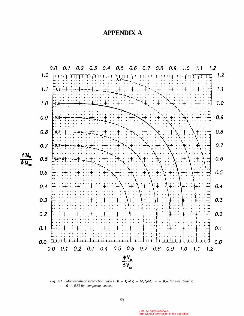
APPENDIX A
59
Fig. A.I. Moment-shear interaction curves. for steel beams;0.85 for composite beams.
© 2003 by American Institute of Steel Construction, Inc. All rights reserved.This publication or any part thereof must not be reproduced in any form without permission of the publisher.
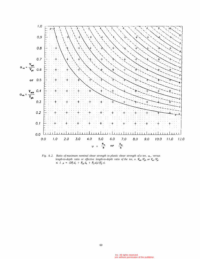
60
Fig. A. 2. Ratio of maximum nominal shear strength to plastic shear strength of a tee, versuslength-to-depth ratio or effective length-to-depth ratio of the tee,
© 2003 by American Institute of Steel Construction, Inc. All rights reserved.This publication or any part thereof must not be reproduced in any form without permission of the publisher.
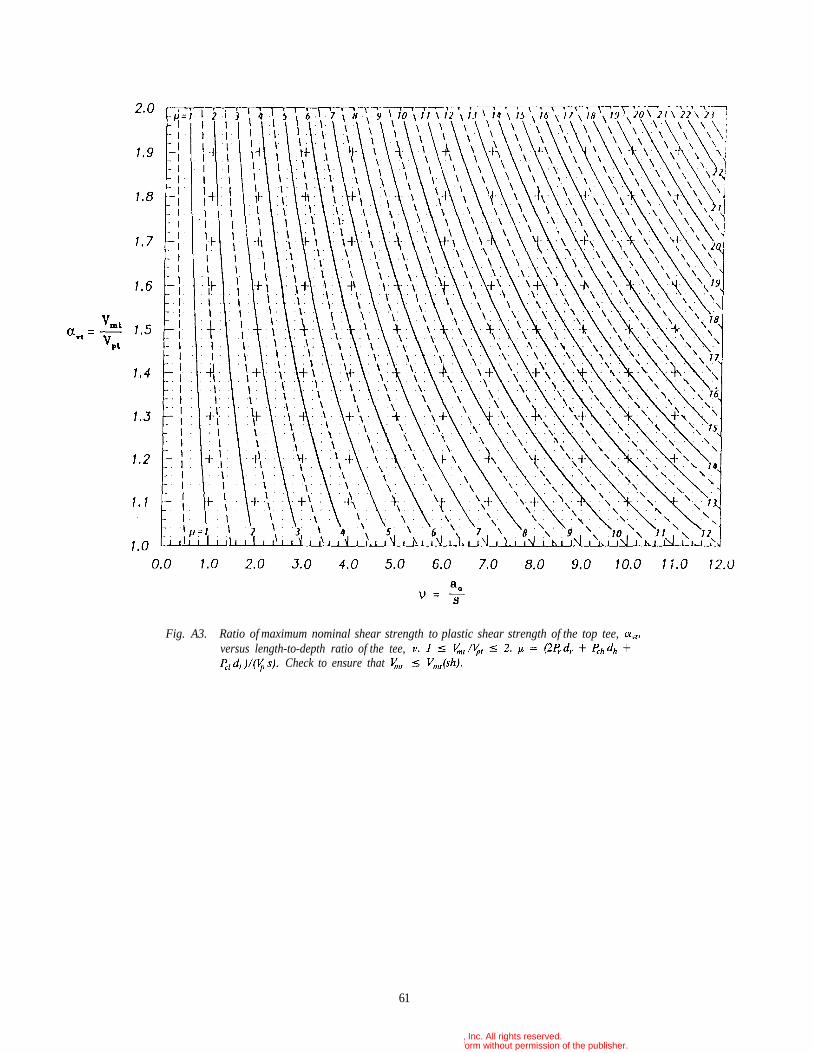
Fig. A3. Ratio of maximum nominal shear strength to plastic shear strength of the top tee,versus length-to-depth ratio of the tee,
Check to ensure that
61
© 2003 by American Institute of Steel Construction, Inc. All rights reserved.This publication or any part thereof must not be reproduced in any form without permission of the publisher.
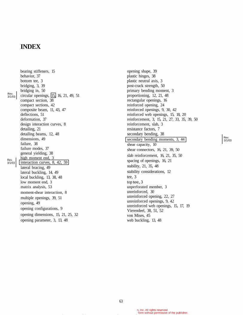
INDEX
bearing stiffeners, 15behavior, 37bottom tee, 3bridging, 3, 39bridging in, 50circular openings, 15, 16, 21, 49, 51compact section, 38compact sections, 42composite beam, 11, 43, 47deflections, 51deformation, 37design interaction curves, 8detailing, 21detailing beams, 12, 48dimensions, 49failure, 38failure modes, 37general yielding, 38high moment end, 3interaction curves, 8, 42, 59lateral bracing, 49lateral buckling, 14, 49local buckling, 13, 38, 48low moment end, 3matrix analysis, 53moment-shear interaction, 8multiple openings, 39, 51opening, 49opening configurations, 9opening dimensions, 15, 21, 25, 32opening parameter, 3, 13, 48
opening shape, 39plastic hinges, 38plastic neutral axis, 3post-crack strength, 50primary bending moment, 3proportioning, 12, 21, 48rectangular openings, 16reinforced opening, 24reinforced openings, 9, 30, 42reinforced web openings, 15, 18, 20reinforcement, 3, 15, 21, 27, 33, 35, 39, 50reinforcement, slab, 3resistance factors, 7secondary bending, 38secondary bending moments, 3, 44shear capacity, 10shear connectors, 16, 21, 39, 50
slab reinforcement, 16, 21, 35, 50spacing of openings, 16, 21stability, 21, 35, 48stability considerations, 12tee, 3top tee, 3unperforated member, 3unreinforced, 30unreinforced opening, 22, 27unreinforced openings, 9, 42unreinforced web openings, 15, 17, 19Vierendeel, 38, 51, 52von Mises, 45web buckling, 13, 48
63
Rev.
Rev.3/1/03
3/1/03
Rev.3/1/03
© 2003 by American Institute of Steel Construction, Inc. All rights reserved.This publication or any part thereof must not be reproduced in any form without permission of the publisher.
DESIGN GUIDE SERIESAmerican Institute of Steel Construction, Inc.One East Wacker Drive, Suite 3100Chicago, Illinois 60601-2001
Pub. No. D802 (3M1093)
© 2003 by American Institute of Steel Construction, Inc. All rights reserved.This publication or any part thereof must not be reproduced in any form without permission of the publisher.