Embed Size (px)
Citation preview
7 International Journal for Modern Trends in Science and Technology
Steady State Thermal Analysis of Thermo Siphon Heat Pipe Photovoltaic Panel Cooling Mechanism Zakariya Kaneesamkandi
Mechanical Engineering Department, King Saud University, Riyadh, Saudi Arabia.
To Cite this Article Zakariya Kaneesamkandi, “Steady State Thermal Analysis of Thermo Siphon Heat Pipe Photovoltaic Panel Cooling Mechanism”, International Journal for Modern Trends in Science and Technology, Vol. 02, Issue 12, 2016, pp. 7-10.
Photovoltaic panels are designed to produce optimum power output only below a particular temperature
which is called the nominal operating cell temperature. Higher operating temperatures of the photovoltaic
panels have an adverse impact on the power output and efficiency. This is because of the predominant
increase in the resistance to the current generated inside the photovoltaic cells which results in reduction of
the power output. Temperature rise of photovoltaic panels due to high solar radiation intensity and ambient
temperature is the problem discussed in this paper. Among various methods currently suggested and tested
by researchers worldwide, thermo siphon heat pipe cooling mechanism is a feasible and low cost option. This
method can be applied to both concentrating and non concentrating photovoltaic panels. The mechanism
used for implementing this method of cooling is described. The effect of cooling on the panel temperature and
the consequent rise in the power output and the efficiency of the photovoltaic panel is analyzed with the help
of a simulation using ANSYS steady state thermal package. The results of using different phase change
temperatures in the thermo siphon cooling mechanism are analyzed.
KEYWORDS: Photovoltaic, Efficiency Enhancement, Thermo siphon, Panel cooling
Copyright © 2016 International Journal for Modern Trends in Science and Technology All rights reserved.
I. INTRODUCTION
Photovoltaic (PV) systems play a key role in
substituting conventional energy sources by acting
as a total or partial energy source as well as a
decentralized energy source. Improvements in
efficiency of these systems helps to enhance the
power output and helps to replace more and more
conventional energy sources with renewable solar
energy. Photovoltaic cells convert only a small
fraction (less than 20 %) of the solar radiation
energy into electrical energy [1]. The balance is
converted into heat within the cell. This makes cell
operating temperature to reach much above the
ambient temperature. Operating temperature plays
a crucial role in the efficiency of photovoltaic
conversion process. Electrical efficiency and power
output of a PV module decreases linearly with
increase in the operating temperature [2]. Cooling
options for photovoltaic panels therefore contribute
to improvement in its efficiency. This can be
achieved by both passive and active methods.
While passive methods involve extra
manufacturing cost, they do not have additional
power requirements as in the case of active
mechanisms.
Passive mechanisms using sheet fins at bottom
of panel with air flow by buoyant effects was
reported to produce marginal efficiency
enhancement [3]. Phase change material used to
absorb a part of the heat produced by the panel
produced positive results [4]. The above methods
gave higher power output from the panel.
Heat pipes are devices used to transport heat
ABSTRACT
International Journal for Modern Trends in Science and Technology
Volume: 02, Issue No: 12, December 2016
ISSN: 2455-3778
http://www.ijmtst.com
8 International Journal for Modern Trends in Science and Technology
Zakariya Kaneesamkandi : Steady State Thermal Analysis of Thermo Siphon Heat Pipe Photovoltaic Panel Cooling Mechanism
from a high temperature area to a low temperature
area by continuous evaporation and condensation
of a working fluid. Heat is absorbed in the
evaporation region which is usually a conduit
below the solar photovoltaic panel and rejected to
the surroundings in the condensation region which
is the upper portion of the pipe extending above the
panel. The condensed fluid heat is then returned
back to the evaporator region. Usually a wick in
used to transport liquid from the condenser region
to the evaporator region. Heat pipes were used for
cooling concentrating photovoltaic panels resulting
in panel operating temperatures as low as 400C at
an ambient temperature of 340C [5]. Thermo
siphon heat pipes (THP) are heat pipes which work
by fluid flow due to gravity effects in contrast to
normal heat pipes which use a wick structure to
transport the fluid by capillary effect. This method
was tested and significant improvement in
performance was reported [6]. However, ineffective
thermal contact between the heat pipe surface and
the back of the solar panel resulted in poor heat
transfer performance. Experiments on an array of
micro heat pipes with air cooling and water cooling
on the condenser side were also reported [7].
Since the fluid is pressurized inside the thermo
siphon during evaporation within the restricted
volume, elevation of the boiling point occurs. Hence
both the nature of the fluid and its operating
pressure determine its operating temperature.
Selection of the proper thermo siphon fluid and
operating pressure determines the thermo siphon
temperature and consequently the panel
temperature. Cooling temperature requirement
depends on the local solar radiation levels, ambient
temperature and wind speed. In order to study the
effect of the thermo siphon fluid phase change
temperature, a steady state model was analyzed
using the ANSYS steady state thermal workbench.
Temperature variation in the panel was simulated
by using two different phase change temperatures
in the thermo siphon. Results show significant
variation in the operating temperature of the
panels.
II. THEORETICAL BACKGROUND
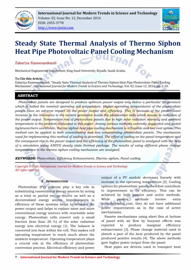
A. Structure of solar panels
Commercial photovoltaic panels are mostly
polycrystalline silicon wafers which are
encapsulated in a layer of ethylene vinyl acetate
(EVA) in order to give rigidity to the wafers [8]. This
encapsulation is further supported at the bottom
by a substrate layer made of tedlar (0.0001m thick)
which is a commercial polyvinyl fluoride film. The
top of the wafer encapsulation is covered by a glass
sheet (0.032m thick). The bottom of the glass sheet
which is in contact with the wafer is provided with
a layer of anti reflective coating (ARC) which
enables more solar radiation to fall on the cells. Fig.
1 gives the general arrangement of a panel.
B. Conversion efficiency
Conversion efficiency depends on different factors including the nature of the photovoltaic cell material and its temperature. Study of performance
Fig.1 Arrangement of photovoltaic panels
of photovoltaic cells was conducted and its efficiency is given by the following equation [9].
log1 rCr TT (1)
In the above equation ηR is the reference module
efficiency at reference cell temperature Tr equal to
25 °C for a reference solar radiation, Iref of 1000
W/m²K. β is the temperature coefficient equal to
0.0045 K-1 and λ is the solar irradiation coefficient
equal to 0.12, respectively. TC represents the cell
temperature and Φ represents the actual intensity
of solar radiation.
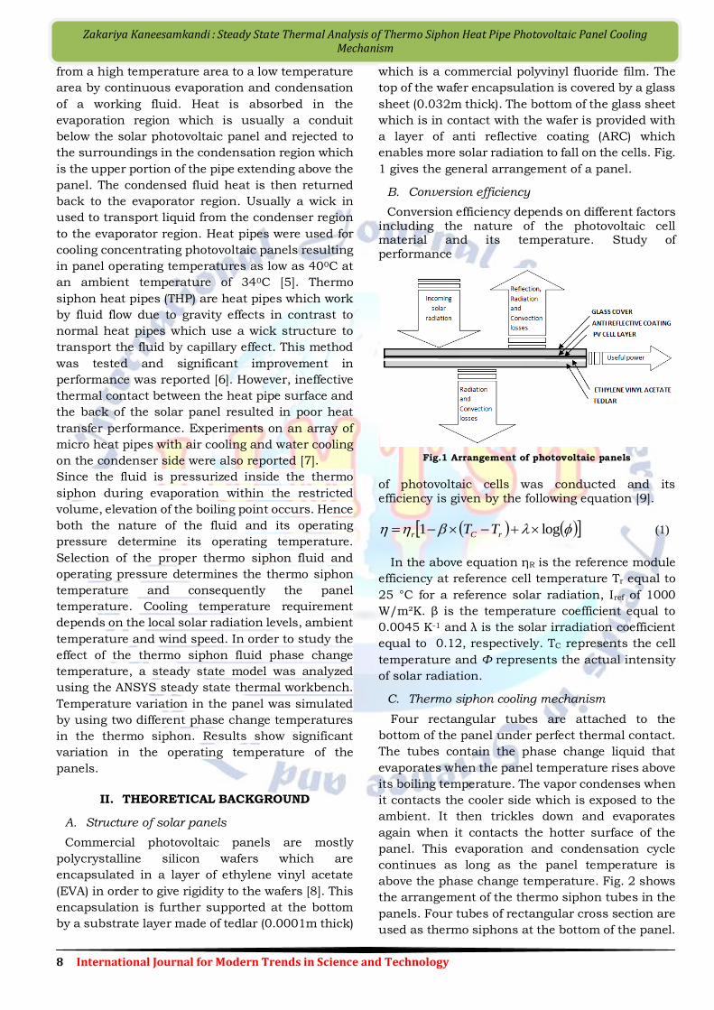
C. Thermo siphon cooling mechanism
Four rectangular tubes are attached to the
bottom of the panel under perfect thermal contact.
The tubes contain the phase change liquid that
evaporates when the panel temperature rises above
its boiling temperature. The vapor condenses when
it contacts the cooler side which is exposed to the
ambient. It then trickles down and evaporates
again when it contacts the hotter surface of the
panel. This evaporation and condensation cycle
continues as long as the panel temperature is
above the phase change temperature. Fig. 2 shows
the arrangement of the thermo siphon tubes in the
panels. Four tubes of rectangular cross section are
used as thermo siphons at the bottom of the panel.
9 International Journal for Modern Trends in Science and Technology
Zakariya Kaneesamkandi : Steady State Thermal Analysis of Thermo Siphon Heat Pipe Photovoltaic Panel Cooling Mechanism
Fig.2 Thermo siphon tubes attached behind panel
III. THE MODEL
The steady state model is made based on the
following assumptions:
Perfect thermal contact between the panel
and the thermo siphon tubes
The phase change liquid operates at a
constant boiling temperature
The vapor cools uniformly at the side exposed
to atmosphere
The temperature of the tube is uniform
throughout its length
Steady state conditions are assumed
Heat produced in the cell layer is conducted
across the glass layer on the top and the
tedlar layer at the bottom of the cell layer.
Solar radiation falls on the panel which is
partially converted to electrical power and the
remaining is lost to the ambient by convection and
radiation. Under steady state condition, the heat
generated (q) by the cell layer of particular volume
(V) for a particular value of radiation depends on
the efficiency (η) of the panel.
𝑞
𝑉= (1 − 𝜂)𝐴𝛷 (2)
‘A’ represents the sun exposed surface area of the
panel and ‘Φ’ indicates the intensity of solar
radiation.
The one dimensional model is governed by the
equations for conduction and convection. Heat flux
produced by the cell layer (𝑞 ) is equal to the heat
conducted on the top and bottom of the cell layer in
one dimension.
𝑞 = 𝐾𝑔 𝑑𝑇
𝑑𝑥 𝑔
+ 𝐾𝑡 𝑑𝑇
𝑑𝑥 𝑡 (3)
Kg and Kt represent the thermal conductivity of
glass and tedlar layers. The heat is further lost by
convection and radiation from the top surface and
bottom surface of the panel.
)()()()( 4444
GskyGBT TTTTTThTThq (4)
hT represents the heat transfer coefficient from
panel top and hB represents the heat transfer
coefficient form the bottom of the panel. 𝑇∝ Ta
represents the free stream ambient temperature
and 𝑇𝐺 represents the ground temperature. σ
represents the Stefan Boltzmann constant.
IV. SIMULATION
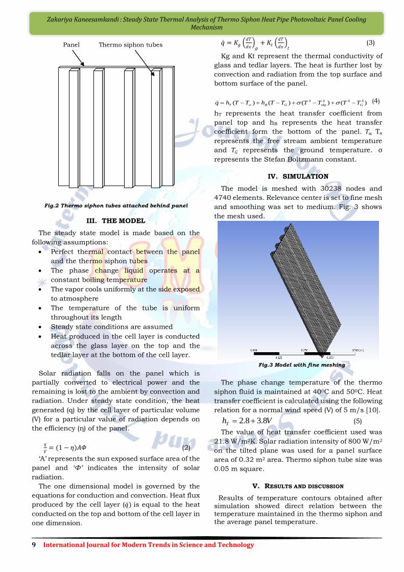
The model is meshed with 30238 nodes and
4740 elements. Relevance center is set to fine mesh
and smoothing was set to medium. Fig. 3 shows
the mesh used.
Fig.3 Model with fine meshing
The phase change temperature of the thermo
siphon fluid is maintained at 400C and 500C. Heat
transfer coefficient is calculated using the following
relation for a normal wind speed (V) of 5 m/s [10].
VhT 8.38.2
(5)
The value of heat transfer coefficient used was
21.8 W/m2K. Solar radiation intensity of 800 W/m2
on the tilted plane was used for a panel surface
area of 0.32 m2 area. Thermo siphon tube size was
0.05 m square.
V. RESULTS AND DISCUSSION
Results of temperature contours obtained after simulation showed direct relation between the temperature maintained in the thermo siphon and the average panel temperature.
Panel Thermo siphon tubes
10 International Journal for Modern Trends in Science and Technology
Zakariya Kaneesamkandi : Steady State Thermal Analysis of Thermo Siphon Heat Pipe Photovoltaic Panel Cooling Mechanism
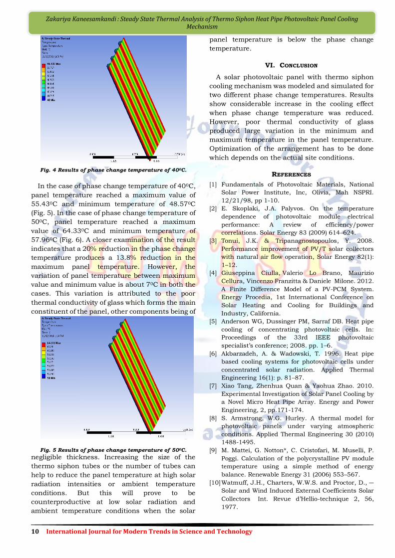
Fig. 4 Results of phase change temperature of 400C.
In the case of phase change temperature of 400C,
panel temperature reached a maximum value of
55.430C and minimum temperature of 48.570C
(Fig. 5). In the case of phase change temperature of
500C, panel temperature reached a maximum
value of 64.330C and minimum temperature of
57.960C (Fig. 6). A closer examination of the result
indicates that a 20% reduction in the phase change
temperature produces a 13.8% reduction in the
maximum panel temperature. However, the
variation of panel temperature between maximum
value and minimum value is about 70C in both the
cases. This variation is attributed to the poor
thermal conductivity of glass which forms the main
constituent of the panel, other components being of
Fig. 5 Results of phase change temperature of 500C.
negligible thickness. Increasing the size of the
thermo siphon tubes or the number of tubes can
help to reduce the panel temperature at high solar
radiation intensities or ambient temperature
conditions. But this will prove to be
counterproductive at low solar radiation and
ambient temperature conditions when the solar
panel temperature is below the phase change
temperature.
VI. CONCLUSION
A solar photovoltaic panel with thermo siphon
cooling mechanism was modeled and simulated for
two different phase change temperatures. Results
show considerable increase in the cooling effect
when phase change temperature was reduced.
However, poor thermal conductivity of glass
produced large variation in the minimum and
maximum temperature in the panel temperature.
Optimization of the arrangement has to be done
which depends on the actual site conditions.
REFERENCES
[1] Fundamentals of Photovoltaic Materials, National
Solar Power Institute, Inc, Olivia, Mah NSPRI.
12/21/98, pp 1-10.
[2] E. Skoplaki, J.A. Palyvos. On the temperature
dependence of photovoltaic module electrical
performance: A review of efficiency/power
correlations. Solar Energy 83 (2009) 614–624.
[3] Tonui, J.K. & Tripanagnostopoulos, Y. 2008.
Performance improvement of PV/T solar collectors
with natural air flow operation, Solar Energy 82(1):
1–12.
[4] Giuseppina Ciulla, Valerio Lo Brano, Maurizio
Cellura, Vincenzo Franzitta & Daniele Milone. 2012.
A Finite Difference Model of a PV-PCM System.
Energy Procedia, 1st International Conference on
Solar Heating and Cooling for Buildings and
Industry, California.
[5] Anderson WG, Dussinger PM, Sarraf DB. Heat pipe
cooling of concentrating photovoltaic cells. In:
Proceedings of the 33rd IEEE photovoltaic
specialist’s conference; 2008. pp. 1–6.
[6] Akbarzadeh, A. & Wadowski, T. 1996. Heat pipe
based cooling systems for photovoltaic cells under
concentrated solar radiation. Applied Thermal
Engineering 16(1): p. 81–87.
[7] Xiao Tang, Zhenhua Quan & Yaohua Zhao. 2010.
Experimental Investigation of Solar Panel Cooling by
a Novel Micro Heat Pipe Array. Energy and Power
Engineering, 2, pp.171-174.
[8] S. Armstrong, W.G. Hurley. A thermal model for
photovoltaic panels under varying atmospheric
conditions. Applied Thermal Engineering 30 (2010)
1488-1495.
[9] M. Mattei, G. Notton*, C. Cristofari, M. Muselli, P.
Poggi. Calculation of the polycrystalline PV module
temperature using a simple method of energy
balance. Renewable Energy 31 (2006) 553–567.
[10] Watmuff, J.H., Charters, W.W.S. and Proctor, D., ―
Solar and Wind Induced External Coefficients Solar
Collectors‖ Int. Revue d’Hellio-technique 2, 56,
1977.