Embed Size (px)
Citation preview
18 International Journal for Modern Trends in Science and Technology
A Motor Drive Controller for High Voltage Circuit Breakers by using Mechanical Operation of PMSM
Srungavrukshapu Sarada1 | Dr.N.Sambasiva Rao2
1PG Scholar, Department of EEE, NRI Institute of Technology, Pothavarapadu, Krishna Dt, Andhra Pradesh, India. 2Professor, Department of EEE, NRI Institute of Technology, Pothavarapadu, Krishna Dt, Andhra Pradesh, India.
To Cite this Article Srungavrukshapu Sarada and Dr.N.Sambasiva Rao, “A Motor Drive Controller for High Voltage Circuit Breakers by using Mechanical Operation of PMSM”, International Journal for Modern Trends in Science and Technology, Vol. 03, Issue 09, September 2017, pp.-18-23.
In this paper, a new type of motor drive operating mechanism of High Voltage Circuit Breakers (HVCB) based
on techniques of power electronics and motor digital control has been studied. In this paper, the structure and
the moving principle of operating mechanism for HVCB is analyzed and the control strategy for PMSM drive
operating mechanism is described. The simulations, calculations and actual tests all indicate that
parameters of the drive-motor such as the rotational inertia, the output torque and the output power will have
impact on the performance of the operating mechanism. The research work of this paper has shown that it is
advisable to adopt motor for driving operating mechanism of HVCB and such mechanism can meet the
requirements for opening and closing operation of HVCBs.
Key Words: High-voltage circuit breaker, motor drive, operation mechanism, permanent-magnet
synchronous motor.
Copyright © 2017 International Journal for Modern Trends in Science and Technology
All rights reserved.
I. INTRODUCTION
High Voltage Circuit-Breakers (HVCBs) are the
very important apparatus responsible for
controlling and protection in the electric power
systems. The operating mechanism is the basic
device which controls the opening and closing
operations of HVCB. At present, there are several
conventional types of operating mechanisms, such
as electromagnetic mechanisms, spring
mechanisms, pneumatic mechanisms and
hydraulic mechanisms. Even though those
conventional mechanisms have many prominent
merits, they also have some insurmountable
limitations. They usually have complex structures
which are difficult to adjust. Therefore periodic
check-ups are necessary and costs for operation
and maintenance are high. Additionally, with those
conventional mechanisms, the process of opening
and closing operations could not be controlled [1]
[2].
In order to overcome the limitations of
conventional operating mechanisms and improve
the operation performance of HVCBs, it is
necessary to do research on new techniques for
operating mechanisms of HVCBs [3-5]. In this
paper, a new type of motor drive operating
mechanism of HVCB has been studied there is only
one rotational part of an electric machine rotor in
the motor-drive mechanism, which is compact in
structure than conventional mechanisms [6]. In
this motor-drive mechanism, capacitor bank is
adopted to store the energy for controlling the
operating mechanism instead of springs or
compressed air [7]. The energy flows out of the
capacitor bank, through the converter made up of
power electronics device and drives the PMSM
Under the control of Digital Signal Processor (DSP),
ABSTRACT
International Journal for Modern Trends in Science and Technology
Volume: 03, Issue No: 09, September 2017
ISSN: 2455-3778
http://www.ijmtst.com
19 International Journal for Modern Trends in Science and Technology
Anjayya Dasari and L.Bangar Raju : Control Strategy of Active Type Super Conducting Fault Current Limiter for Minimization of Fault Effects in Presence of Distribution Generation Resources
the PMSM directly drives the moving contact of
HVCB to conduct opening and closing operations
[8]. As no chains, hydraulic fluid or compressed air
is needed to transfer the energy, this mechanism
has higher efficiency and reliability. A closed-loop
control strategy is adopted in the motor drive
mechanism and the operation speed of the moving
contact could be precisely controlled the change of
the ambient temperature and the supply voltage
will also have little impact on the motor [9].
Besides, since there are already sensors for
velocity, position, current and voltage in the control
system of the motor, it is easy to realize continuous
self check and monitoring for the operating
mechanism and the HVCB.
As a whole, The Motor Drive offers a totally new
and versatile way to operate HVCBs. It has the
following advantages: I) Fewer moving parts and
impacts, low noise level, simple and reliable
system; 2) No special power demand, no high
short-term loads; 3) Operation curve could be
selected due to the practical situation, with
closed-loop control; 4) Contact travel is
independent of ageing and change in ambient
temperature; 5) Condition monitoring is inherent
without the need for additional sensors.
The main focus of this paper is the control
techniques for thetravel curve of the breaker. The
speed, position, current, andvoltage sensors are
installed in the control system to obtain
continuous self testing and monitoring.
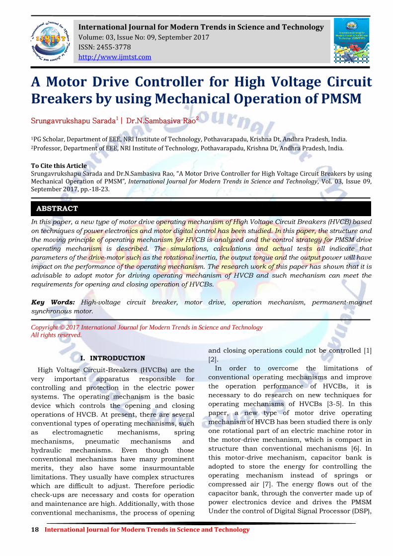
Fig.1 shows a demonstration of a CB operating
device. Inthe opening operation driven by the
motor-drive mechanism,the crank (8) rotates
counterclockwise; pulling the insulatingrod (7)
down. This will quickly drive the moving arc
contact(3) downwards. At the end of the opening
operation, the motorapplies a clockwise torque, as
a buffering force, on the drivingshaft (9)
todecelerate the crank (8) rotation. The moving
arccontact (3) speed will smoothly decrease and the
mechanicalimpact will be limited.
During the closing operation, the crank (8)
rotates clockwisein the closing operation, pushing
the insulation rod (7) upwards.The moving contact
(3) accelerates up toward thefixed contact.Using
preset calculations and control for speed and
position, themotor then applies a reverse
counterclockwise torque to decelerate the moving
contact, thus toreduce the mechanical
impactbetween the breaker contacts.
Fig.1. CB actuating device, where: 1:fixed arc contact, 2: -nozzle,
3: movingarc contact, 4: puffer volume, 5: valve, 6: moving rod, 7:
insulating rod, 8: crank,9: driving shaft.
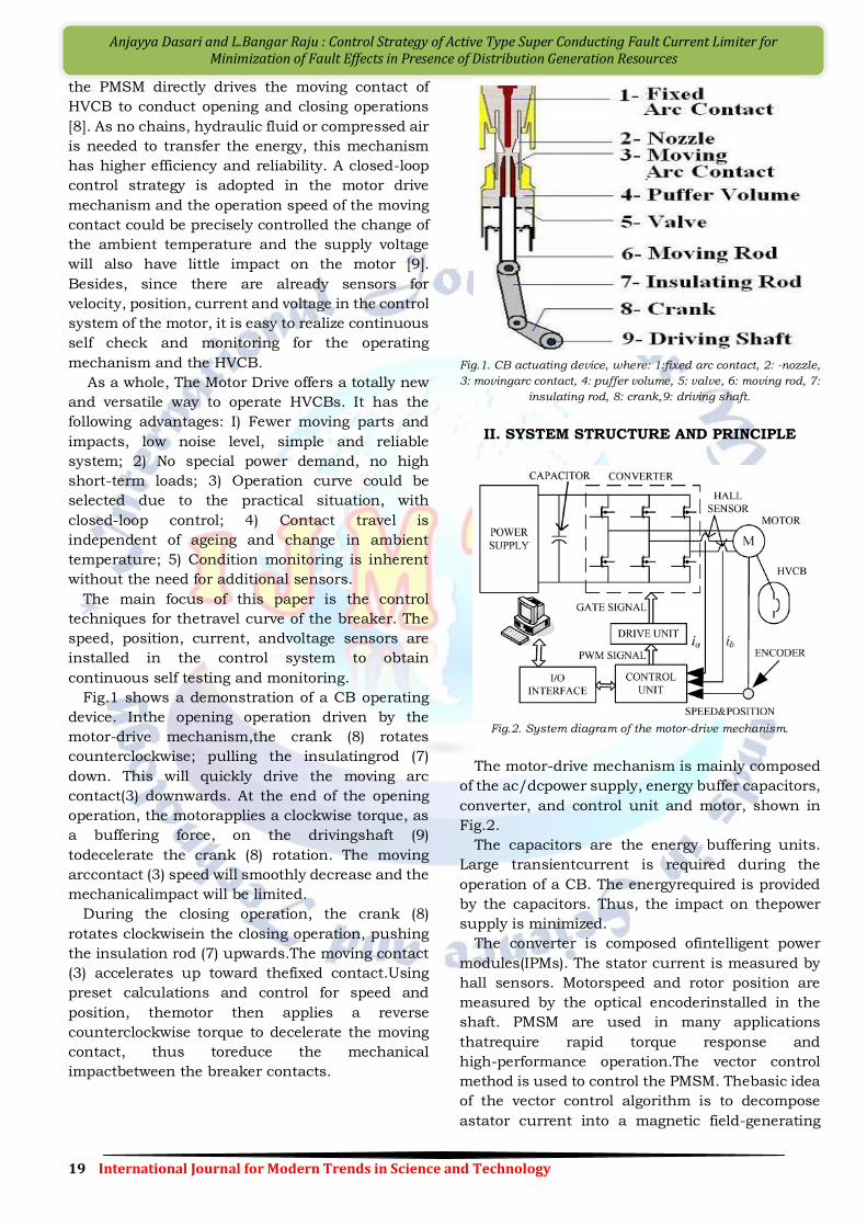
II. SYSTEM STRUCTURE AND PRINCIPLE
Fig.2. System diagram of the motor-drive mechanism.
The motor-drive mechanism is mainly composed
of the ac/dcpower supply, energy buffer capacitors,
converter, and control unit and motor, shown in
Fig.2.
The capacitors are the energy buffering units.
Large transientcurrent is required during the
operation of a CB. The energyrequired is provided
by the capacitors. Thus, the impact on thepower
supply is minimized.
The converter is composed ofintelligent power
modules(IPMs). The stator current is measured by
hall sensors. Motorspeed and rotor position are
measured by the optical encoderinstalled in the
shaft. PMSM are used in many applications
thatrequire rapid torque response and
high-performance operation.The vector control
method is used to control the PMSM. Thebasic idea
of the vector control algorithm is to decompose
astator current into a magnetic field-generating
20 International Journal for Modern Trends in Science and Technology
Anjayya Dasari and L.Bangar Raju : Control Strategy of Active Type Super Conducting Fault Current Limiter for Minimization of Fault Effects in Presence of Distribution Generation Resources
component anda torque generating component.
After decomposition, bothcomponents can be
separately controlled like a dc machine.The speed
and torque of PMSM are separately controlled.
The mathematical model of a PMSM is [9] and [10]
(1)
Where
(2)
𝑢𝑑 and 𝑢𝑞 are the d, q axis voltages, pis the
differential operator (d)/(dt),𝑖𝑑 and 𝑖𝑞 are the d, q
axis stator currents, Ld and Lq are the d, q axis
inductances, ψd and ψq are the d, q axis stator flux
linkages, while Rand ωare the stator resistance
andinverter frequency, respectively. ψr is the flux
linkage due tothe rotor magnets linking the stator.
The electric torque is
(3)
And the equation for the motor dynamics is
(4)
pmis the number of pole pairs, TLis the load
torque, Bis thedamping coefficient, Ωis the rotor
speed, Jand is the equivalentinertia.
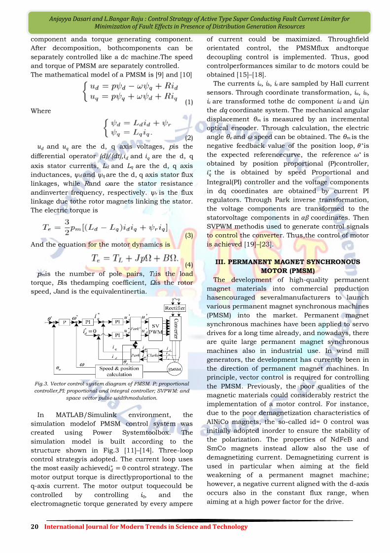
Fig.3. Vector control system diagram of PMSM. P: proportional
controller,PI: proportional and integral controller; SVPWM: and
space vector pulse widthmodulation.
In MATLAB/Simulink environment, the
simulation modelof PMSM control system was
created using Power Systemtoolbox. The
simulation model is built according to the
structure shown in Fig.3 [11]–[14]. Three-loop
control strategyis adopted. The current loop uses
the most easily achieved𝑖𝑑∗ = 0 control strategy. The
motor output torque is directlyproportional to the
q-axis current. The motor output toquecould be
controlled by controlling iq, and the
electromagnetic torque generated by every ampere
of current could be maximized. Throughfield
orientated control, the PMSMflux andtorque
decoupling control is implemented. Thus, good
controlperformances similar to dc motors could be
obtained [15]–[18].
The currents ia, ib, ic are sampled by Hall current
sensors. Through coordinate transformation, ia, ib,
ic are transformed tothe dc component id and iqin
the dq coordinate system. The mechanical angular
displacement θm is measured by an incremental
optical encoder. Through calculation, the electric
angle θe and ω speed can be obtained. The θm is the
negative feedback value of the position loop, 𝜃∗is
the expected referencecurve, the reference 𝜔∗ is
obtained by position proportional (P)controller,
𝑖𝑞∗ the is obtained by speed Proportional and
Integral(PI) controller and the voltage components
in dq coordinates are obtained by current PI
regulators. Through Park inverse transformation,
the voltage components are transformed to the
statorvoltage components in 𝛼𝛽 coordinates. Then
SVPWM methodis used to generate control signals
to control the converter. Thus,the control of motor
is achieved [19]–[23].
III. PERMANENT MAGNET SYNCHRONOUS
MOTOR (PMSM)
The development of high-quality permanent
magnet materials into commercial production
hasencouraged severalmanufacturers to launch
various permanent magnet synchronous machines
(PMSM) into the market. Permanent magnet
synchronous machines have been applied to servo
drives for a long time already, and nowadays, there
are quite large permanent magnet synchronous
machines also in industrial use. In wind mill
generators, the development has currently been in
the direction of permanent magnet machines. In
principle, vector control is required for controlling
the PMSM. Previously, the poor qualities of the
magnetic materials could considerably restrict the
implementation of a motor control. For instance,
due to the poor demagnetization characteristics of
AlNiCo magnets, the so-called id= 0 control was
initially adopted inorder to ensure the stability of
the polarization. The properties of NdFeB and
SmCo magnets instead allow also the use of
demagnetizing current. Demagnetizing current is
used in particular when aiming at the field
weakening of a permanent magnet machine;
however, a negative current aligned with the d-axis
occurs also in the constant flux range, when
aiming at a high power factor for the drive.
21 International Journal for Modern Trends in Science and Technology
Anjayya Dasari and L.Bangar Raju : Control Strategy of Active Type Super Conducting Fault Current Limiter for Minimization of Fault Effects in Presence of Distribution Generation Resources
The basic differences to the control principlesof
other AC motors are due to the magnetic properties
of permanent magnets, and particularly tothe fact
that the permanent magnet material is a part of the
magnetic circuit of the machine, and therefore has
a significant influence on its reluctance. The
relative permeability of permanent magnet
materials 𝜇𝑟 is close to one, and therefore the
effective direct air gap of the PMSM often becomes
very large. Thereby also the inductances of the
machine – particularly in machines in which the
magnets are located on the rotor surface – usually
remain rather low. Another difference is that the
direct synchronous inductance, when employing
embedded magnets, can be less than the
quadrature value, while the ratio is the opposite in
a separately excited salient-pole synchronous
machine.
The field weakening of a PM machine has to be
implemented by using a demagnetizing stator
current. If the inductances are very low, the field
weakening is not a rational option. In the surface
magnet type servo motors, the per unit value of the
synchronous inductance is typically in the range
ld= 0.2−0.4. An adequate rotation speed range is
often achieved by dimensioning the rated
frequency of the machine to be sufficientlyhigh.
When employing embedded magnets, however, the
inductances may be dimensioned so high thatthe
rotation speed range can be expanded. Often when
staying within the limits of the rated current, the
upper limit remains at about double the rated
speed at maximum. However, when applying field
weakening, it should be borne in mind that the
back emf caused by the permanent magnets is
directly proportional to the rotation speed of the
machine. If the demagnetizing current is lost for
some reason, the inverter has to withstand this
voltage undamaged; however, the danger of the
breakdown of the inverter is obvious.
Thewithstanding of DC link capacitors to voltages
amounts typically only to 30–50 % above the rated
voltage.
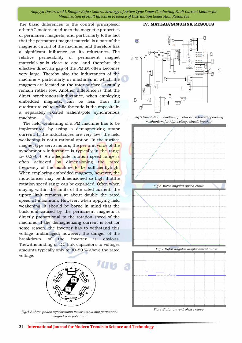
Fig.4 A three-phase synchronous motor with a one permanent
magnet pair pole rotor
IV. MATLAB/SIMULINK RESULTS
Fig.5 Simulation modeling of motor drive based operating
mechanism for high voltage circuit breaker
Fig.6 Motor angular speed curve
Fig.7 Motor angular displacement curve
Fig.8 Stator current phase curve
22 International Journal for Modern Trends in Science and Technology
Anjayya Dasari and L.Bangar Raju : Control Strategy of Active Type Super Conducting Fault Current Limiter for Minimization of Fault Effects in Presence of Distribution Generation Resources
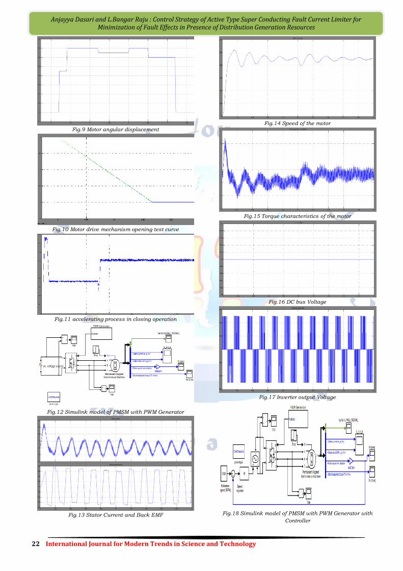
Fig.9 Motor angular displacement
Fig.10 Motor drive mechanism opening test curve
Fig.11 accelerating process in closing operation
Fig.12 Simulink model of PMSM with PWM Generator
Fig.13 Stator Current and Back EMF
Fig.14 Speed of the motor
Fig.15 Torque characteristics of the motor
Fig.16 DC bus Voltage
Fig.17 Inverter output Voltage
Fig.18 Simulink model of PMSM with PWM Generator with
Controller
23 International Journal for Modern Trends in Science and Technology
Anjayya Dasari and L.Bangar Raju : Control Strategy of Active Type Super Conducting Fault Current Limiter for Minimization of Fault Effects in Presence of Distribution Generation Resources
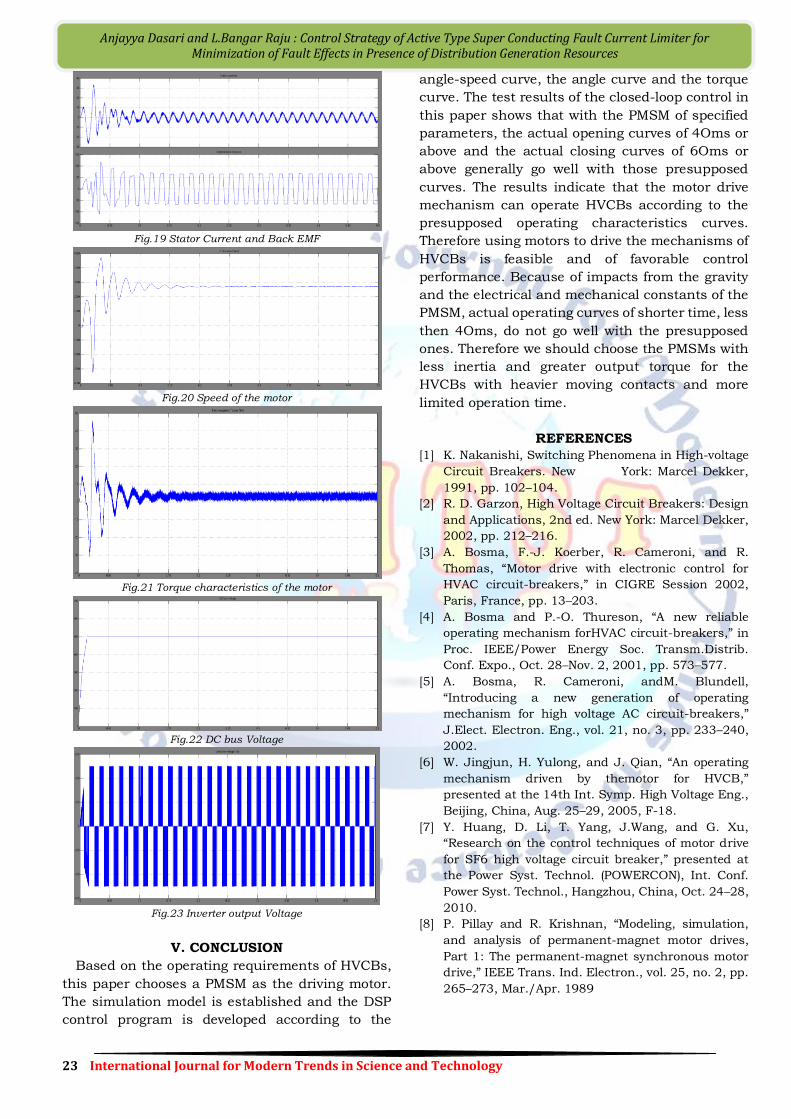
Fig.19 Stator Current and Back EMF
Fig.20 Speed of the motor
Fig.21 Torque characteristics of the motor
Fig.22 DC bus Voltage
Fig.23 Inverter output Voltage
V. CONCLUSION
Based on the operating requirements of HVCBs,
this paper chooses a PMSM as the driving motor.
The simulation model is established and the DSP
control program is developed according to the
angle-speed curve, the angle curve and the torque
curve. The test results of the closed-loop control in
this paper shows that with the PMSM of specified
parameters, the actual opening curves of 4Oms or
above and the actual closing curves of 6Oms or
above generally go well with those presupposed
curves. The results indicate that the motor drive
mechanism can operate HVCBs according to the
presupposed operating characteristics curves.
Therefore using motors to drive the mechanisms of
HVCBs is feasible and of favorable control
performance. Because of impacts from the gravity
and the electrical and mechanical constants of the
PMSM, actual operating curves of shorter time, less
then 4Oms, do not go well with the presupposed
ones. Therefore we should choose the PMSMs with
less inertia and greater output torque for the
HVCBs with heavier moving contacts and more
limited operation time.
REFERENCES
[1] K. Nakanishi, Switching Phenomena in High-voltage
Circuit Breakers. New York: Marcel Dekker,
1991, pp. 102–104.
[2] R. D. Garzon, High Voltage Circuit Breakers: Design
and Applications, 2nd ed. New York: Marcel Dekker,
2002, pp. 212–216.
[3] A. Bosma, F.-J. Koerber, R. Cameroni, and R.
Thomas, “Motor drive with electronic control for
HVAC circuit-breakers,” in CIGRE Session 2002,
Paris, France, pp. 13–203.
[4] A. Bosma and P.-O. Thureson, “A new reliable
operating mechanism forHVAC circuit-breakers,” in
Proc. IEEE/Power Energy Soc. Transm.Distrib.
Conf. Expo., Oct. 28–Nov. 2, 2001, pp. 573–577.
[5] A. Bosma, R. Cameroni, andM. Blundell,
“Introducing a new generation of operating
mechanism for high voltage AC circuit-breakers,”
J.Elect. Electron. Eng., vol. 21, no. 3, pp. 233–240,
2002.
[6] W. Jingjun, H. Yulong, and J. Qian, “An operating
mechanism driven by themotor for HVCB,”
presented at the 14th Int. Symp. High Voltage Eng.,
Beijing, China, Aug. 25–29, 2005, F-18.
[7] Y. Huang, D. Li, T. Yang, J.Wang, and G. Xu,
“Research on the control techniques of motor drive
for SF6 high voltage circuit breaker,” presented at
the Power Syst. Technol. (POWERCON), Int. Conf.
Power Syst. Technol., Hangzhou, China, Oct. 24–28,
2010.
[8] P. Pillay and R. Krishnan, “Modeling, simulation,
and analysis of permanent-magnet motor drives,
Part 1: The permanent-magnet synchronous motor
drive,” IEEE Trans. Ind. Electron., vol. 25, no. 2, pp.
265–273, Mar./Apr. 1989