Embed Size (px)
Citation preview
16:9 Format 1.3 MegaPixel
11x Zoom Auto Focus Camera
STC-AFCM133DV
Product Specification
STC-AFCM133DV
Product Specifications 2 Ver 1.0
!CAUTION
RISK OF ELECTRIC SHOCK
DO NOT OPEN
CAUTION:
TO REDUCE THE RISK OF ELECTRIC SHOCK, DO NOT
REMOVE COVER (OR BACK). NO USER SERVICEABLE
PARTS INSIDE.
REFER SERVICING TO QUALIFIED SERVICE PERSONNEL.
The lightning flash with arrowhead
symbol, within an equilateral triangle,
is intended to alert the user to the
presence of uninsulated “dangerous
voltage” within the product’s
enclosure that may be of sufficient
magnitude to constitute a risk of
electric shock to persons.
The exclamation point within an
equilateral triangle is intended to alert
the user to the presence of important
operating and maintenance (servicing)
instructions in the literature
accompanying the appliance.!
Warning:
This equipment generates and uses radio frequency energy and if
not installed and used properly, I.e., in strict accordance with the
instruction manual, may cause harmful interference to radio
communications. It has been tested and found to comply with the
limits for a Class A computing device pursuant to Subpart J of Part
15 of FCC Rules, which are designed to provide reasonable
protection against such interference when operated in a commercial
environment.
For U.S.A.
Warning:
This digital apparatus does not exceed the Class A limits for radio
noise emissions from digital apparatus set out in the Radio
Interference Regulations of the Canadian Department of
Communications.
For Canada
WARNING:
TO PREVENT FIRE OR SHOCK HAZARD, DO NOT EXPOSE
THIS APPLIANCE TO RAIN OR MOISTURE.
Safety Precautions
Product Precautions
Handle the camera with care. Do not abuse the camera. Avoid striking or shaking it. Improper handling or storage could damage the camera.
Do not pull or damage the camera cable.
During camera use, do not wrap he unit in any material. This will cause the internal temperature of the unit to increase.
Do not expose the camera to moisture, or do not try to operate it in wet areas.
Do not operate the camera beyond its temperature, humidity and power source ratings.
While the camera is not being used, keep the lens or lens cap on the camera to prevent dust or contamination from getting in the CCD or filter area and scratching or damaging this area.
Do not keep the camera under the following conditions:
In wet, moist, and high humidity areas
Under hot direct sunlight
In high temperature areas
Near an object that releases a strong magnetic or electric field
Areas with strong vibrations
Use a soft cloth to clean the camera. Use pressured air spray to clean the surface of the glass. DO not scratch the surface of the glass.
STC-AFCM133DV
Product Specifications 3 Ver 1.0
Copyright & Disclaimer
Sensor Technologies America, Inc. (DBA Sentech America) believes the contents and specifications of its website, catalog,
documentation and ads are correct; however, Sentech America provides no representation or warranty regarding such information or
product(s) contained therein. It is requested that Sentech America be given appropriate acknowledgement in any subsequent use of
such work by a third party.
While every effort has been made to ensure that the details contained in Sentech America’s website and all documentation are correct
and up-to-date, Sentech America assumes no liability, legal or otherwise for any errors in listings, specifications, part numbers,
process, software or model applications. Sentech America reserves the right to change specifications, product descriptions, product
quality, pricing and application at any time without prior written or oral notice. Any party using such information assumes all risk for
any and all damaged caused to themselves, a third party and/or property by virtue of incorrect information and/or failure of these
products. By installing and/or using a Sentech America software development kit or other similar product and/or information obtained
from Sentech America’s website, catalog, documentation or ads, you hereby accept and understand these stated terms and conditions.
STC-AFCM133DV
Product Specifications 4 Ver 1.0
Content I. Specifications ..................................................................................................................................................... 5-10
A. Electronic Specifications / Mechanical Specifications / Environmental Specifications .................................................. 5
B. Connector Specifications ................................................................................................................................................ 6
1. Mechanical Drawings .................................................................................................................................................. 6
2. Connector-A: Video Output (DVI) ............................................................................................................................... 6
3. Connector-B: Video Output (DVI, CN207) ................................................................................................................... 7
4. Connector-C: Video Output (LVDS, CN204) ................................................................................................................ 7
5. Connector-D: HD/VD signal output (CN206)............................................................................................................... 8
6. Connector-E (CN303): Power Input ............................................................................................................................ 8
7. Connector-F (CN305): External Switch Connection .................................................................................................... 9
8. Connector-G (CN304): UART Communication ............................................................................................................ 9
C. Output timing ................................................................................................................................................................ 10
II. Camera Operations ......................................................................................................................................... 11-16
A. ALC Operations ............................................................................................................................................................. 11
B. Shutter Settings ............................................................................................................................................................. 11
C. External Switch Assignable Functions ........................................................................................................................... 12
D. User Configurable Functions.................................................................................................................................... 13-16
III. Dimensions ......................................................................................................................................................... 17
STC-AFCM133DV
Product Specifications 5 Ver 1.0
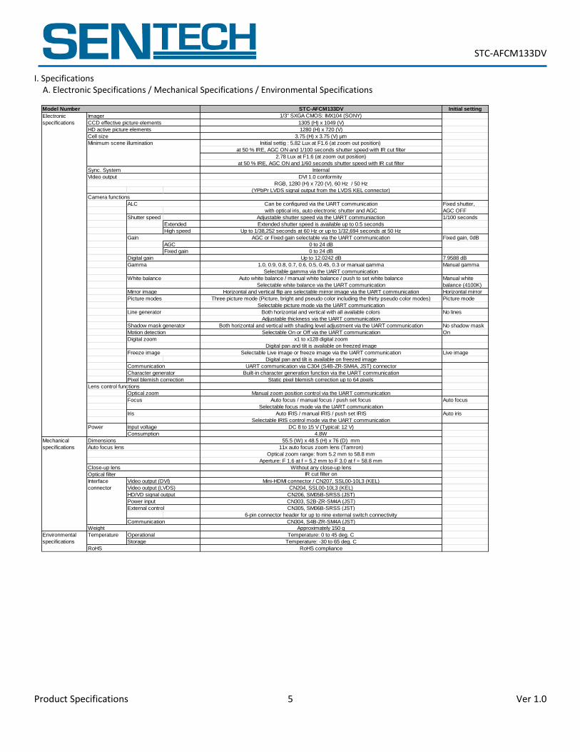
I. Specifications A. Electronic Specifications / Mechanical Specifications / Environmental Specifications
Initial setting
Fixed shutter,
AGC OFF
Shutter speed 1/100 seconds
Extended
High speed
Fixed gain, 0dB
AGC
Fixed gain
7.9588 dB
Manual gamma
Manual white
balance (4100K)
Horizontal mirror
Picture mode
No lines
No shadow mask
On
Live image
Auto focus
Auto iris
STC-AFCM133DV
CN206, SM05B-SRSS (JST)
Static pixel blemish correction up to 64 pixels
55.5 (W) x 48.5 (H) x 76 (D) mm
Without any close-up lens
CN204, SSL00-10L3 (KEL)
1.0, 0.9, 0.8, 0.7, 0.6, 0.5, 0.45, 0.3 or manual gamma
(YPbPr LVDS signal output from the LVDS KEL connector)
2.78 Lux at F1.6 (at zoom out position)
at 50 % IRE, AGC ON and 1/60 seconds shutter speed with IR cut filter
Initial settig : 5.82 Lux at F1.6 (at zoom out position)
Internal
Adjustable shutter speed via the UART communiaction
Extended shutter speed is available up to 0.5 seconds
at 50 % IRE, AGC ON and 1/100 seconds shutter speed with IR cut filter
Selectable Live image or freeze image via the UART communication
UART communication via C304 (S4B-ZR-SM4A, JST) connector
Selectable white balance via the UART communication
Digital pan and tilt is available on freezed image
Selectable picture mode via the UART communication
Selectable gamma via the UART communication
Auto white balance / manual white balance / push to set white balance
Can be configured via the UART communication
Environmental
specifications
Temperature
Mechanical
specifications 11x auto focus zoom lens (Tamron)
Aperture: F 1.6 at f = 5.2 mm to F 3.0 at f = 58.8 mm
Electronic
specifications
Camera functions
ALC
Gain
Gamma
Minimum scene illumination
Sync. System
Video output
Line generator
Optical zoom range: from 5.2 mm to 58.8 mm
x1 to x128 digital zoom
4.8W
Manual zoom position control via the UART communication
Auto IRIS / manual IRIS / push set IRIS
DC 8 to 15 V (Typical: 12 V)
Auto focus / manual focus / push set focus
3.75 (H) x 3.75 (V) µm
RoHS compliance
Temperature: 0 to 45 deg. C
Temperature: -30 to 65 deg. C
IR cut filter on
CN304, S4B-ZR-SM4A (JST)
CN303, S2B-ZR-SM4A (JST)
CN305, SM06B-SRSS (JST)
Mini-HDMI connector / CN207, SSL00-10L3 (KEL)
6-pin connector header for up to nine external switch connectivity
Approximately 150 g
Up to 1/38,252 seconds at 60 Hz or up to 1/32,694 seconds at 50 Hz
with optical iris, auto electronic shutter and AGC
Model Number
Imager
CCD effective picture elements
HD active picture elements
Cell size
Selectable IRIS control mode via the UART communication
Selectable focus mode via the UART communication
Selectable On or Off via the UART communication
Horizontal and vertical flip are selectable mirror image via the UART communication
Adjustable thickness via the UART communication
Both horizontal and vertical with shading level adjustment via the UART communication
Three picture mode (Picture, bright and pseudo color including the thirty pseudo color modes)
Both horizontal and vertical with all available colors
Built-in character generation function via the UART communication
Digital pan and tilt is available on freezed image
1/3" SXGA CMOS: IMX104 (SONY)
1305 (H) x 1049 (V)
AGC or Fixed gain selectable via the UART communication
DVI 1.0 conformity
1280 (H) x 720 (V)
RGB, 1280 (H) x 720 (V), 60 Hz / 50 Hz
Picture modes
White balance
Mirror image
0 to 24 dB
0 to 24 dB
Digital gain Up to 12.0242 dB
Input voltage
Digital zoom
Motion detection
Shadow mask generator
Optical zoom
Freeze image
Communication
Character generator
Lens control functions
Pixel blemish correction
Power input
External control
Interface
connector
Dimensions
Consumption
Auto focus lens
RoHS
Communication
Operational
Storage
Weight
Focus
Video output (DVI)
Iris
HD/VD signal output
Close-up lens
Optical filter
Video output (LVDS)
Power
STC-AFCM133DV
Product Specifications 6 Ver 1.0
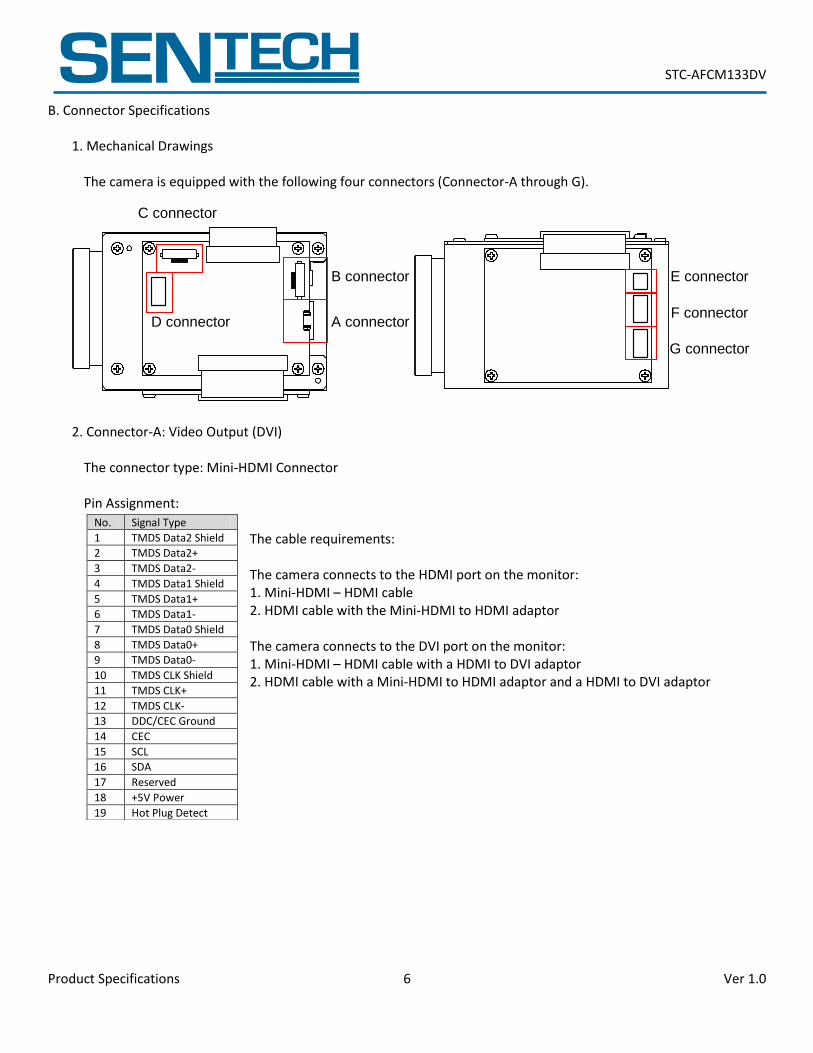
B. Connector Specifications
1. Mechanical Drawings
The camera is equipped with the following four connectors (Connector-A through G).
2. Connector-A: Video Output (DVI)
The connector type: Mini-HDMI Connector
Pin Assignment:
The cable requirements:
The camera connects to the HDMI port on the monitor: 1. Mini-HDMI – HDMI cable 2. HDMI cable with the Mini-HDMI to HDMI adaptor
The camera connects to the DVI port on the monitor: 1. Mini-HDMI – HDMI cable with a HDMI to DVI adaptor 2. HDMI cable with a Mini-HDMI to HDMI adaptor and a HDMI to DVI adaptor
No. Signal Type
1 TMDS Data2 Shield
2 TMDS Data2+
3 TMDS Data2-
4 TMDS Data1 Shield
5 TMDS Data1+
6 TMDS Data1-
7 TMDS Data0 Shield
8 TMDS Data0+
9 TMDS Data0-
10 TMDS CLK Shield
11 TMDS CLK+
12 TMDS CLK-
13 DDC/CEC Ground
14 CEC
15 SCL
16 SDA
17 Reserved
18 +5V Power
19 Hot Plug Detect
A connector
B connector
C connector
D connector
E connector
F connector
G connector
STC-AFCM133DV
Product Specifications 7 Ver 1.0
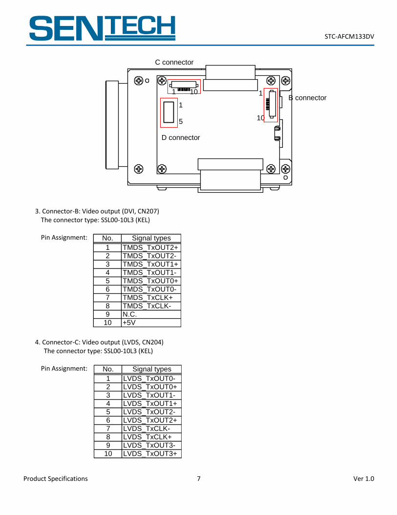
3. Connector-B: Video output (DVI, CN207) The connector type: SSL00-10L3 (KEL)
Pin Assignment:
4. Connector-C: Video output (LVDS, CN204) The connector type: SSL00-10L3 (KEL)
Pin Assignment:
C connector
B connector
D connector
1 10
1 5
1 10
No. Signal types
1 TMDS_TxOUT2+2 TMDS_TxOUT2-3 TMDS_TxOUT1+4 TMDS_TxOUT1-5 TMDS_TxOUT0+6 TMDS_TxOUT0-7 TMDS_TxCLK+8 TMDS_TxCLK-9 N.C.
10 +5V
No. Signal types
1 LVDS_TxOUT0-2 LVDS_TxOUT0+3 LVDS_TxOUT1-4 LVDS_TxOUT1+5 LVDS_TxOUT2-6 LVDS_TxOUT2+7 LVDS_TxCLK-8 LVDS_TxCLK+9 LVDS_TxOUT3-
10 LVDS_TxOUT3+
STC-AFCM133DV
Product Specifications 8 Ver 1.0
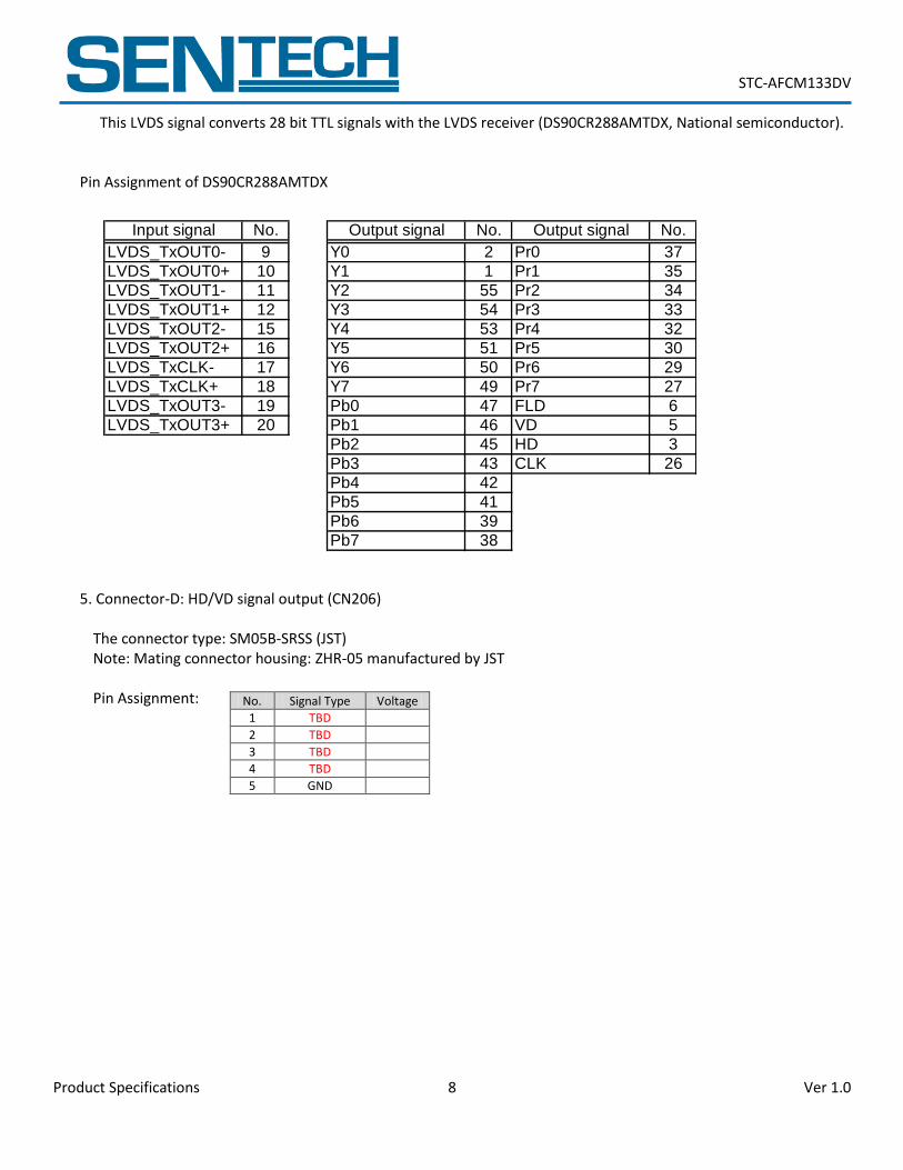
This LVDS signal converts 28 bit TTL signals with the LVDS receiver (DS90CR288AMTDX, National semiconductor). Pin Assignment of DS90CR288AMTDX
5. Connector-D: HD/VD signal output (CN206)
The connector type: SM05B-SRSS (JST) Note: Mating connector housing: ZHR-05 manufactured by JST
Pin Assignment:
No. Signal Type Voltage
1 TBD
2 TBD
3 TBD
4 TBD
5 GND
Input signal No. Output signal No. Output signal No.
LVDS_TxOUT0- 9 Y0 2 Pr0 37
LVDS_TxOUT0+ 10 Y1 1 Pr1 35
LVDS_TxOUT1- 11 Y2 55 Pr2 34
LVDS_TxOUT1+ 12 Y3 54 Pr3 33
LVDS_TxOUT2- 15 Y4 53 Pr4 32
LVDS_TxOUT2+ 16 Y5 51 Pr5 30
LVDS_TxCLK- 17 Y6 50 Pr6 29
LVDS_TxCLK+ 18 Y7 49 Pr7 27
LVDS_TxOUT3- 19 Pb0 47 FLD 6
LVDS_TxOUT3+ 20 Pb1 46 VD 5
Pb2 45 HD 3
Pb3 43 CLK 26
Pb4 42
Pb5 41
Pb6 39
Pb7 38
STC-AFCM133DV
Product Specifications 9 Ver 1.0
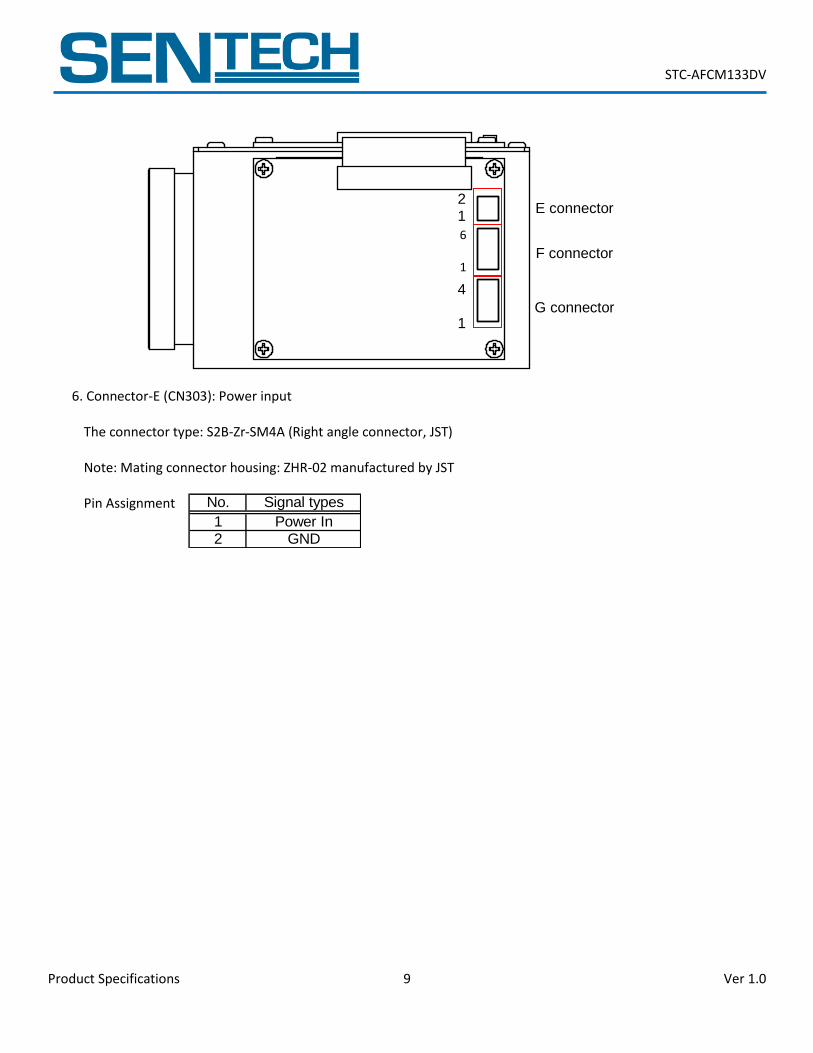
6. Connector-E (CN303): Power input
The connector type: S2B-Zr-SM4A (Right angle connector, JST) Note: Mating connector housing: ZHR-02 manufactured by JST
Pin Assignment
4 1
2 1
E connector
F connector
G connector
6 1
No. Signal types
1 Power In2 GND
STC-AFCM133DV
Product Specifications 10 Ver 1.0
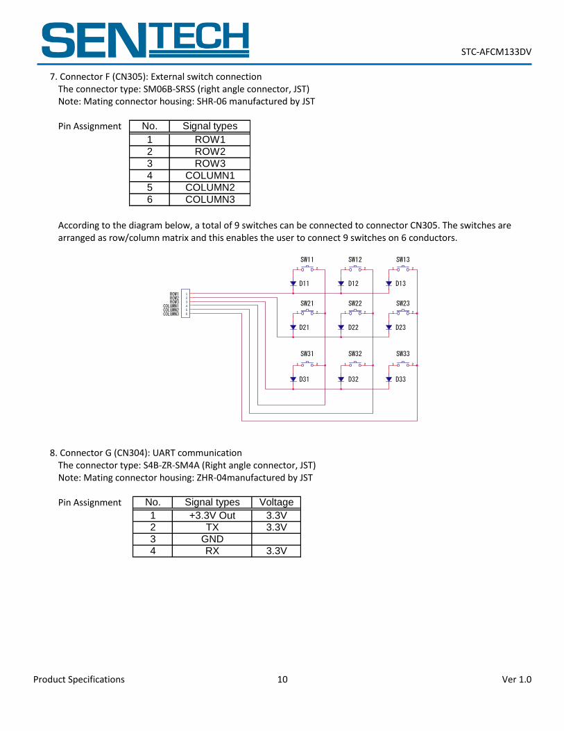
7. Connector F (CN305): External switch connection The connector type: SM06B-SRSS (right angle connector, JST) Note: Mating connector housing: SHR-06 manufactured by JST
Pin Assignment
According to the diagram below, a total of 9 switches can be connected to connector CN305. The switches are arranged as row/column matrix and this enables the user to connect 9 switches on 6 conductors.
1 2 1 2 1 2
1 2 1 2 1 2
1 2 1 2 1 2
1
2
3
4
5
6
SW11
SW21
SW12 SW13
SW22 SW23
SW31 SW32 SW33
ROW2ROW3
ROW1
COLUMN2COLUMN3
COLUMN1
D11
D21
D31
D12
D22
D32
D13
D23
D33
8. Connector G (CN304): UART communication The connector type: S4B-ZR-SM4A (Right angle connector, JST) Note: Mating connector housing: ZHR-04manufactured by JST
Pin Assignment
No. Signal types
1 ROW1
2 ROW2
3 ROW3
4 COLUMN1
5 COLUMN2
6 COLUMN3
No. Signal types Voltage
1 +3.3V Out 3.3V2 TX 3.3V3 GND4 RX 3.3V
STC-AFCM133DV
Product Specifications 11 Ver 1.0
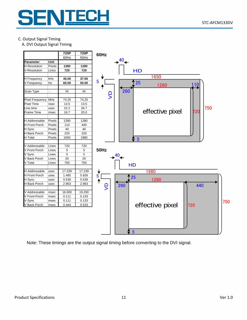
C. Output Signal Timing A. DVI Output Signal Timing
60Hz
effective pixel
1280
720
HD
VD
750
1650
260
25
40
5
1105
50Hz
effective pixel
1280
720
HD
VD
750
1980
260
25
40
5
440
5
Note: These timings are the output signal timing before converting to the DVI signal.
720P 720P
60Hz 50Hz
Parameter Unit
H-Resolution Pixels 1280 1280
V-Resolution Lines 720 720
H Frequency kHz 45.00 37.50
V Frequency Hz 60.00 50.00
Scan Type - NI NI
Pixel Frequency MHz 74.25 74.25
Pixel Time nsec 13.5 13.5
Line time usec 22.2 26.7
Frame Time msec 16.7 20.0
H Addressable Pixels 1280 1280
H Front Porch Pixels 110 440
H Sync Pixels 40 40
H Back Porch Pixels 220 220
H Total Pixels 1650 1980
V Addressable Lines 720 720
V Front Porch Lines 5 5
V Sync Lines 5 5
V Back Porch Lines 20 20
V Total Lines 750 750
H Addressable usec 17.239 17.239
H Front Porch usec 1.485 5.926
H Sync usec 0.539 0.539
H Back Porch usec 2.963 2.963
V Addressable msec 16.000 19.200
V Front Porch msec 0.111 0.133
V Sync msec 0.111 0.133
V Back Porch msec 0.444 0.533
STC-AFCM133DV
Product Specifications 12 Ver 1.0
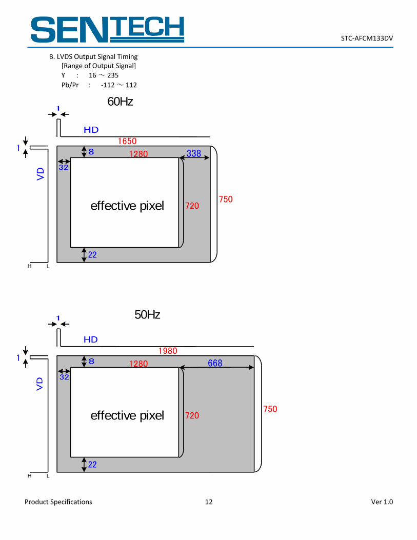
B. LVDS Output Signal Timing [Range of Output Signal]
Y : 16 ~ 235
Pb/Pr : -112 ~ 112
effective pixel
1280
720
HD
VD
750
1650
32
8
1
22
3381
LH
60Hz
50Hz
effective pixel
1280
720
HD
VD
750
1980
32
8
1
22
6681
LH
STC-AFCM133DV
Product Specifications 13 Ver 1.0
II. Camera Operations
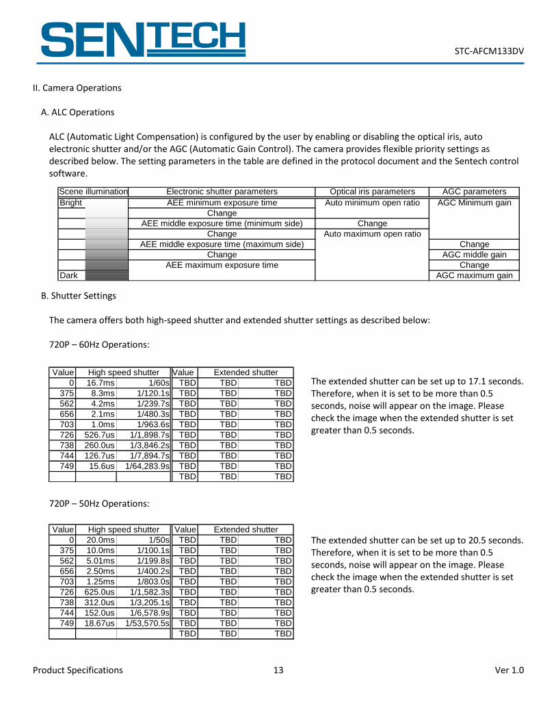
A. ALC Operations
ALC (Automatic Light Compensation) is configured by the user by enabling or disabling the optical iris, auto electronic shutter and/or the AGC (Automatic Gain Control). The camera provides flexible priority settings as described below. The setting parameters in the table are defined in the protocol document and the Sentech control software.
B. Shutter Settings
The camera offers both high-speed shutter and extended shutter settings as described below: 720P – 60Hz Operations:
The extended shutter can be set up to 17.1 seconds. Therefore, when it is set to be more than 0.5 seconds, noise will appear on the image. Please check the image when the extended shutter is set greater than 0.5 seconds.
720P – 50Hz Operations:
The extended shutter can be set up to 20.5 seconds. Therefore, when it is set to be more than 0.5 seconds, noise will appear on the image. Please check the image when the extended shutter is set greater than 0.5 seconds.
Value Value
0 16.7ms 1/60s TBD TBD TBD
375 8.3ms 1/120.1s TBD TBD TBD
562 4.2ms 1/239.7s TBD TBD TBD
656 2.1ms 1/480.3s TBD TBD TBD
703 1.0ms 1/963.6s TBD TBD TBD
726 526.7us 1/1,898.7s TBD TBD TBD
738 260.0us 1/3,846.2s TBD TBD TBD
744 126.7us 1/7,894.7s TBD TBD TBD
749 15.6us 1/64,283.9s TBD TBD TBD
TBD TBD TBD
High speed shutter Extended shutter
Value Value
0 20.0ms 1/50s TBD TBD TBD
375 10.0ms 1/100.1s TBD TBD TBD
562 5.01ms 1/199.8s TBD TBD TBD
656 2.50ms 1/400.2s TBD TBD TBD
703 1.25ms 1/803.0s TBD TBD TBD
726 625.0us 1/1,582.3s TBD TBD TBD
738 312.0us 1/3,205.1s TBD TBD TBD
744 152.0us 1/6,578.9s TBD TBD TBD
749 18.67us 1/53,570.5s TBD TBD TBD
TBD TBD TBD
High speed shutter Extended shutter
Scene illumination Electronic shutter parameters Optical iris parameters AGC parameters
Bright AEE minimum exposure time Auto minimum open ratio AGC Minimum gain
Change
AEE middle exposure time (minimum side) Change
Change Auto maximum open ratio
AEE middle exposure time (maximum side) Change
Change AGC middle gain
AEE maximum exposure time Change
Dark AGC maximum gain
STC-AFCM133DV
Product Specifications 14 Ver 1.0
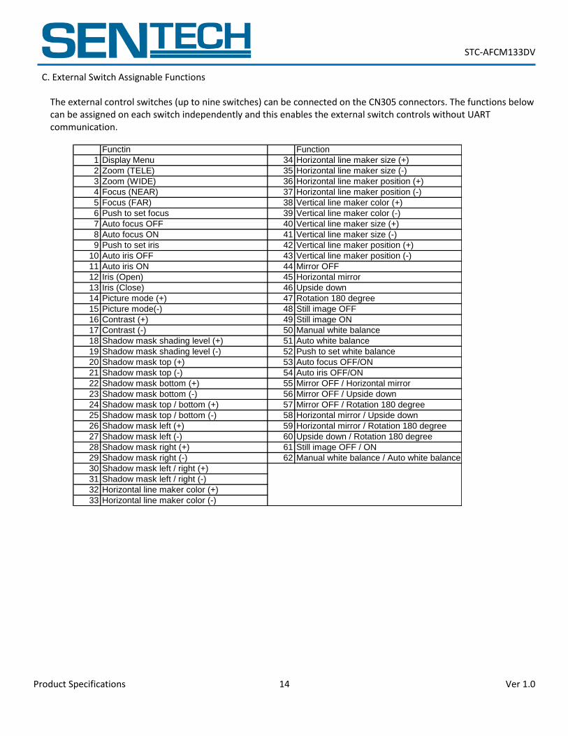
C. External Switch Assignable Functions
The external control switches (up to nine switches) can be connected on the CN305 connectors. The functions below can be assigned on each switch independently and this enables the external switch controls without UART communication.
Functin Function
1 Display Menu 34 Horizontal line maker size (+)
2 Zoom (TELE) 35 Horizontal line maker size (-)
3 Zoom (WIDE) 36 Horizontal line maker position (+)
4 Focus (NEAR) 37 Horizontal line maker position (-)
5 Focus (FAR) 38 Vertical line maker color (+)
6 Push to set focus 39 Vertical line maker color (-)
7 Auto focus OFF 40 Vertical line maker size (+)
8 Auto focus ON 41 Vertical line maker size (-)
9 Push to set iris 42 Vertical line maker position (+)
10 Auto iris OFF 43 Vertical line maker position (-)
11 Auto iris ON 44 Mirror OFF
12 Iris (Open) 45 Horizontal mirror
13 Iris (Close) 46 Upside down
14 Picture mode (+) 47 Rotation 180 degree
15 Picture mode(-) 48 Still image OFF
16 Contrast (+) 49 Still image ON
17 Contrast (-) 50 Manual white balance
18 Shadow mask shading level (+) 51 Auto white balance
19 Shadow mask shading level (-) 52 Push to set white balance
20 Shadow mask top (+) 53 Auto focus OFF/ON
21 Shadow mask top (-) 54 Auto iris OFF/ON
22 Shadow mask bottom (+) 55 Mirror OFF / Horizontal mirror
23 Shadow mask bottom (-) 56 Mirror OFF / Upside down
24 Shadow mask top / bottom (+) 57 Mirror OFF / Rotation 180 degree
25 Shadow mask top / bottom (-) 58 Horizontal mirror / Upside down
26 Shadow mask left (+) 59 Horizontal mirror / Rotation 180 degree
27 Shadow mask left (-) 60 Upside down / Rotation 180 degree
28 Shadow mask right (+) 61 Still image OFF / ON
29 Shadow mask right (-) 62 Manual white balance / Auto white balance
30 Shadow mask left / right (+)
31 Shadow mask left / right (-)
32 Horizontal line maker color (+)
33 Horizontal line maker color (-)
STC-AFCM133DV
Product Specifications 15 Ver 1.0
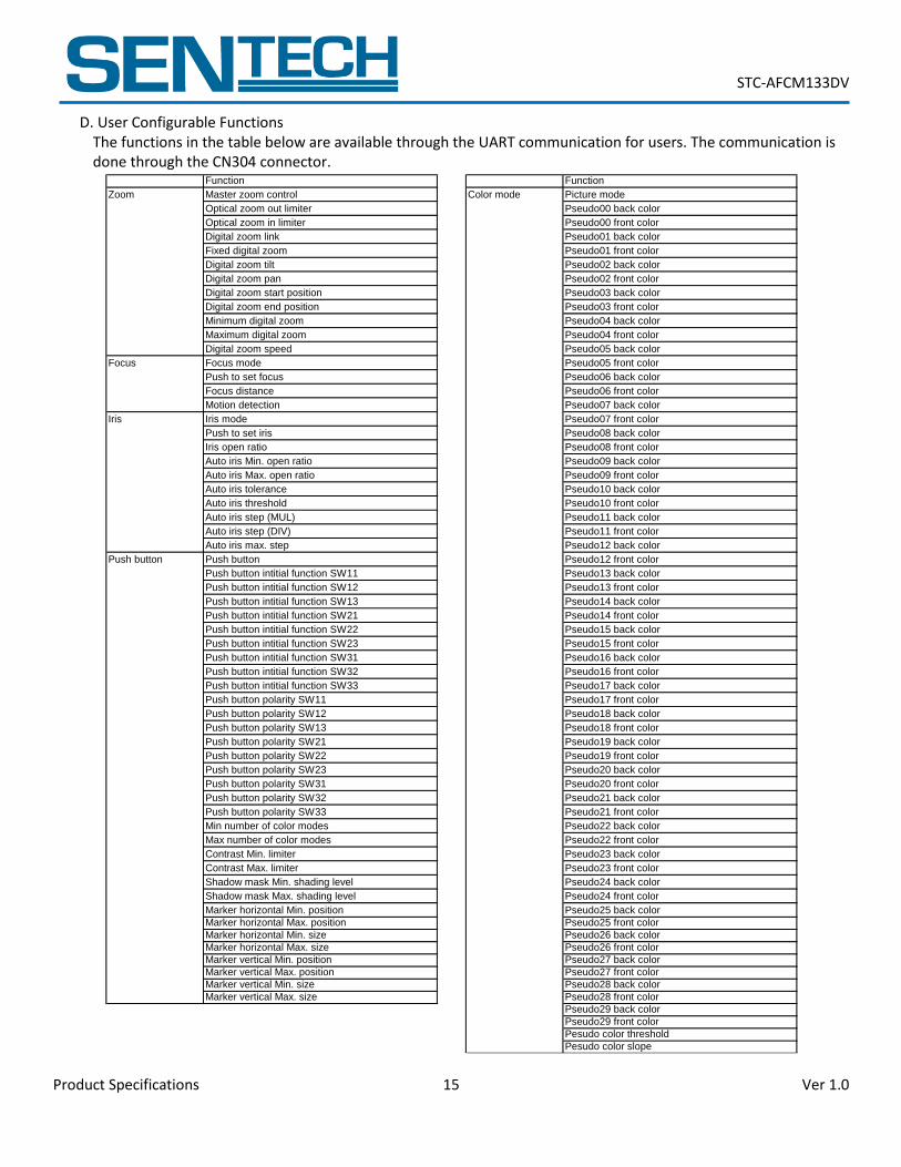
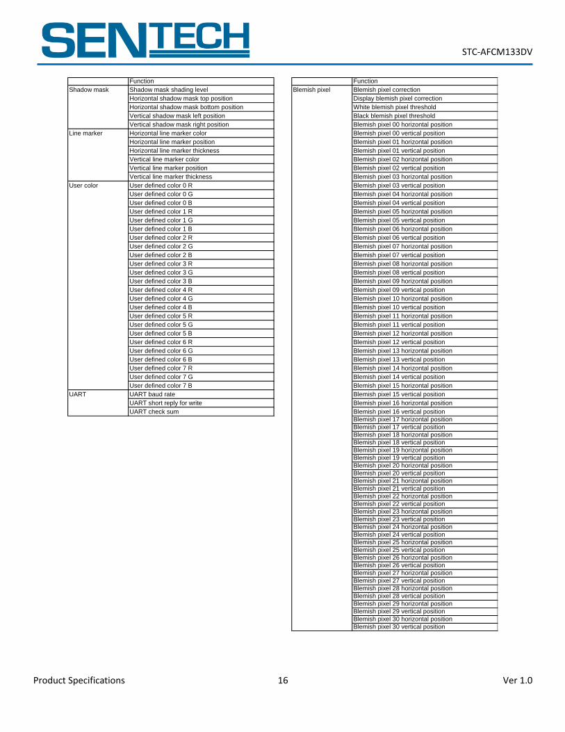
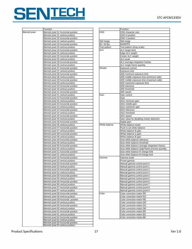
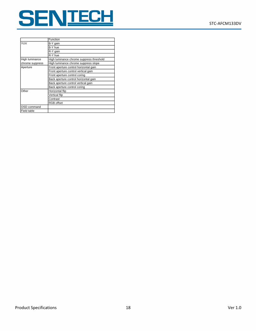
D. User Configurable Functions The functions in the table below are available through the UART communication for users. The communication is done through the CN304 connector.
Function Function
Zoom Master zoom control Color mode Picture mode
Optical zoom out limiter Pseudo00 back color
Optical zoom in limiter Pseudo00 front color
Digital zoom link Pseudo01 back color
Fixed digital zoom Pseudo01 front color
Digital zoom tilt Pseudo02 back color
Digital zoom pan Pseudo02 front color
Digital zoom start position Pseudo03 back color
Digital zoom end position Pseudo03 front color
Minimum digital zoom Pseudo04 back color
Maximum digital zoom Pseudo04 front color
Digital zoom speed Pseudo05 back color
Focus Focus mode Pseudo05 front color
Push to set focus Pseudo06 back color
Focus distance Pseudo06 front color
Motion detection Pseudo07 back color
Iris Iris mode Pseudo07 front color
Push to set iris Pseudo08 back color
Iris open ratio Pseudo08 front color
Auto iris Min. open ratio Pseudo09 back color
Auto iris Max. open ratio Pseudo09 front color
Auto iris tolerance Pseudo10 back color
Auto iris threshold Pseudo10 front color
Auto iris step (MUL) Pseudo11 back color
Auto iris step (DIV) Pseudo11 front color
Auto iris max. step Pseudo12 back color
Push button Push button Pseudo12 front color
Push button intitial function SW11 Pseudo13 back color
Push button intitial function SW12 Pseudo13 front color
Push button intitial function SW13 Pseudo14 back color
Push button intitial function SW21 Pseudo14 front color
Push button intitial function SW22 Pseudo15 back color
Push button intitial function SW23 Pseudo15 front color
Push button intitial function SW31 Pseudo16 back color
Push button intitial function SW32 Pseudo16 front color
Push button intitial function SW33 Pseudo17 back color
Push button polarity SW11 Pseudo17 front color
Push button polarity SW12 Pseudo18 back color
Push button polarity SW13 Pseudo18 front color
Push button polarity SW21 Pseudo19 back color
Push button polarity SW22 Pseudo19 front color
Push button polarity SW23 Pseudo20 back color
Push button polarity SW31 Pseudo20 front color
Push button polarity SW32 Pseudo21 back color
Push button polarity SW33 Pseudo21 front color
Min number of color modes Pseudo22 back color
Max number of color modes Pseudo22 front color
Contrast Min. limiter Pseudo23 back color
Contrast Max. limiter Pseudo23 front color
Shadow mask Min. shading level Pseudo24 back color
Shadow mask Max. shading level Pseudo24 front color
Marker horizontal Min. position Pseudo25 back color
Marker horizontal Max. position Pseudo25 front color
Marker horizontal Min. size Pseudo26 back color
Marker horizontal Max. size Pseudo26 front color
Marker vertical Min. position Pseudo27 back color
Marker vertical Max. position Pseudo27 front color
Marker vertical Min. size Pseudo28 back color
Marker vertical Max. size Pseudo28 front color
Pseudo29 back color
Pseudo29 front color
Pesudo color threshold
Pesudo color slope
STC-AFCM133DV
Product Specifications 16 Ver 1.0
Function Function
Shadow mask Shadow mask shading level Blemish pixel Blemish pixel correction
Horizontal shadow mask top position Display blemish pixel correction
Horizontal shadow mask bottom position White blemish pixel threshold
Vertical shadow mask left position Black blemish pixel threshold
Vertical shadow mask right position Blemish pixel 00 horizontal position
Line marker Horizontal line marker color Blemish pixel 00 vertical position
Horizontal line marker position Blemish pixel 01 horizontal position
Horizontal line marker thickness Blemish pixel 01 vertical position
Vertical line marker color Blemish pixel 02 horizontal position
Vertical line marker position Blemish pixel 02 vertical position
Vertical line marker thickness Blemish pixel 03 horizontal position
User color User defined color 0 R Blemish pixel 03 vertical position
User defined color 0 G Blemish pixel 04 horizontal position
User defined color 0 B Blemish pixel 04 vertical position
User defined color 1 R Blemish pixel 05 horizontal position
User defined color 1 G Blemish pixel 05 vertical position
User defined color 1 B Blemish pixel 06 horizontal position
User defined color 2 R Blemish pixel 06 vertical position
User defined color 2 G Blemish pixel 07 horizontal position
User defined color 2 B Blemish pixel 07 vertical position
User defined color 3 R Blemish pixel 08 horizontal position
User defined color 3 G Blemish pixel 08 vertical position
User defined color 3 B Blemish pixel 09 horizontal position
User defined color 4 R Blemish pixel 09 vertical position
User defined color 4 G Blemish pixel 10 horizontal position
User defined color 4 B Blemish pixel 10 vertical position
User defined color 5 R Blemish pixel 11 horizontal position
User defined color 5 G Blemish pixel 11 vertical position
User defined color 5 B Blemish pixel 12 horizontal position
User defined color 6 R Blemish pixel 12 vertical position
User defined color 6 G Blemish pixel 13 horizontal position
User defined color 6 B Blemish pixel 13 vertical position
User defined color 7 R Blemish pixel 14 horizontal position
User defined color 7 G Blemish pixel 14 vertical position
User defined color 7 B Blemish pixel 15 horizontal position
UART UART baud rate Blemish pixel 15 vertical position
UART short reply for write Blemish pixel 16 horizontal position
UART check sum Blemish pixel 16 vertical position
Blemish pixel 17 horizontal position
Blemish pixel 17 vertical position
Blemish pixel 18 horizontal position
Blemish pixel 18 vertical position
Blemish pixel 19 horizontal position
Blemish pixel 19 vertical position
Blemish pixel 20 horizontal position
Blemish pixel 20 vertical position
Blemish pixel 21 horizontal position
Blemish pixel 21 vertical position
Blemish pixel 22 horizontal position
Blemish pixel 22 vertical position
Blemish pixel 23 horizontal position
Blemish pixel 23 vertical position
Blemish pixel 24 horizontal position
Blemish pixel 24 vertical position
Blemish pixel 25 horizontal position
Blemish pixel 25 vertical position
Blemish pixel 26 horizontal position
Blemish pixel 26 vertical position
Blemish pixel 27 horizontal position
Blemish pixel 27 vertical position
Blemish pixel 28 horizontal position
Blemish pixel 28 vertical position
Blemish pixel 29 horizontal position
Blemish pixel 29 vertical position
Blemish pixel 30 horizontal position
Blemish pixel 30 vertical position
STC-AFCM133DV
Product Specifications 17 Ver 1.0
Function Function
Blemish pixel Blemish pixel 31 horizontal position OSD OSD character size
Blemish pixel 31 vertical position OSD H position
Blemish pixel 32 horizontal position OSD V position
Blemish pixel 32 vertical position Still image Still image
Blemish pixel 33 horizontal position 60 / 50 fps 60/50FPS
Blemish pixel 33 vertical position Test pattern Test pattern (Gray scale)
Blemish pixel 34 horizontal position ALC ALC target level
Blemish pixel 34 vertical position Edge ALC weight
Blemish pixel 35 horizontal position Center ALC weight
Blemish pixel 35 vertical position ALC peak
Blemish pixel 36 horizontal position ALC average integration frames
Blemish pixel 36 vertical position ALC single-frame quantity
Blemish pixel 37 horizontal position Shutter Exposure control
Blemish pixel 37 vertical position Exposure time
Blemish pixel 38 horizontal position AEE minimum exposure time
Blemish pixel 38 vertical position AEE middle exposure time (minimum side)
Blemish pixel 39 horizontal position AEE middle exposure time (maximum side)
Blemish pixel 39 vertical position AEE maximum exposure time
Blemish pixel 40 horizontal position AEE tolerance
Blemish pixel 40 vertical position AEE threshold
Blemish pixel 41 horizontal position AEE speed
Blemish pixel 41 vertical position Gain Gain control
Blemish pixel 42 horizontal position Gain
Blemish pixel 42 vertical position AGC minimum gain
Blemish pixel 43 horizontal position AGC middle gain
Blemish pixel 43 vertical position AGC maximum gain
Blemish pixel 44 horizontal position AGC tolerance
Blemish pixel 44 vertical position AGC threshold
Blemish pixel 45 horizontal position AGC speed
Blemish pixel 45 vertical position Gain value for disabling motion detection
Blemish pixel 46 horizontal position Digital gain
Blemish pixel 46 vertical position White balance White balance mode
Blemish pixel 47 horizontal position Push to set white balance
Blemish pixel 47 vertical position White balance R gain
Blemish pixel 48 horizontal position White balance G gain
Blemish pixel 48 vertical position White balance B gain
Blemish pixel 49 horizontal position Auto white balance tolerance
Blemish pixel 49 vertical position Auto white balance threshold
Blemish pixel 50 horizontal position Auto white balance average integration frames
Blemish pixel 50 vertical position Auto white balance singl-frame process quantity
Blemish pixel 51 horizontal position Auto white balance R change limit
Blemish pixel 51 vertical position Auto white balance B change limit
Blemish pixel 52 horizontal position Gamma Gamma mode
Blemish pixel 52 vertical position Preset gamma
Blemish pixel 53 horizontal position Manual gamma control point 0
Blemish pixel 53 vertical position Manual gamma control point 1
Blemish pixel 54 horizontal position Manual gamma control point 2
Blemish pixel 54 vertical position Manual gamma control point 3
Blemish pixel 55 horizontal position Manual gamma control point 4
Blemish pixel 55 vertical position Manual gamma control point 5
Blemish pixel 56 horizontal position Manual gamma control point 6
Blemish pixel 56 vertical position Manual gamma control point 7
Blemish pixel 57 horizontal position Manual gamma control point 8
Blemish pixel 57 vertical position Manual gamma control point 9
Blemish pixel 58 horizontal position Color Color correction matrix RR
Blemish pixel 58 vertical position Color correction matrix RG
Blemish pixel 59 horizontal position Color correction matrix RB
Blemish pixel 59 vertical position Color correction matrix GR
Blemish pixel 60 horizontal position Color correction matrix GG
Blemish pixel 60 vertical position Color correction matrix GB
Blemish pixel 61 horizontal position Color correction matrix BR
Blemish pixel 61 vertical position Color correction matrix BG
Blemish pixel 62 horizontal position Color correction matrix BB
Blemish pixel 62 vertical position
Blemish pixel 63 horizontal position
Blemish pixel 63 vertical position
STC-AFCM133DV
Product Specifications 18 Ver 1.0
Function
YUV B-Y gain
B-Y hue
R-Y gain
R-Y hue
High luminance High luminance chrome suppress threshold
chrome suppress High luminance chrome suppress slope
Aperture Front aperture control horizontal gain
Front aperture control vertical gain
Front aperture control coring
Back aperture control horizontal gain
Back aperture control vertical gain
Back aperture control coring
Other Horizontal flip
Vertical flip
Contrast
RGB offset
OSD command
Field table
STC-AFCM133DV
Product Specifications 19 Ver 1.0
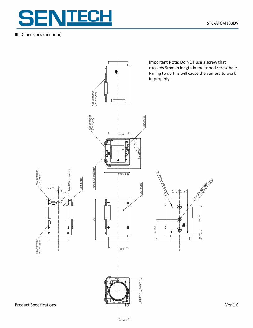
III. Dimensions (unit mm)
Important Note: Do NOT use a screw that exceeds 5mm in length in the tripod screw hole. Failing to do this will cause the camera to work improperly.
Min
i-H
DM
I co
nn
ecto
r
JK
A-P
CB
35
5.5
(M
ax)25 (
Max)
JK
A-P
CB
1
Min
i-H
DM
I co
nn
ecto
r
KE
L c
onnecto
r
(LV
DS
sig
na
l)
76
24.5
φ36
42.35
48.5 (Max)
+/-
0.2
KE
L c
onnecto
r
(DV
I sig
na
l)
KE
L c
onnecto
r
(DV
I sig
nal)
3.5
JK
A-P
CB
2
8.523.8
+/-
0.2
22.45+/-0.5
38
+/-
0.3
15
+/-
0.3
50
+/-
0.2
15+/-0.5
15+/-0.5
KE
L c
onnecto
r
(LV
DS
sig
na
l)
1/4"
-20U
NC
(Trip
od)
(Ins
ert l
engt
h le
ss th
an 5
)
4-M
2
(Inse
rt le
ngth
less
than 3
)
STC-AFCM133DV
Product Specifications 20 Ver 1.0
Revisions
Rev Date Changes Note
1.0 3/5/2013 New document
STC-AFCM133DV
Product Specifications 21 Ver 1.0
Sensor Technologies America, Inc. 1345 Valwood Pkwy, Suite 320 Carrollton, Texas 75006-6891 TEL (972) 481-9223 FAX (972) 481-9209 URL http://www.sentechamerica.com/
Sensor Technology Co., Ltd. 7F, Harada Center Building 9-17, Naka cho 4chrome Atsugi-city, Kanagawa 243-0018 Japan TEL +81-46-295-7061 FAX +81-46-295-7066 URL http://www.sentech.co.jp/
Taiwan Sensor Technology, Inc. 3F-6, No. 9, Aiguo W, Rd,. Jhong Jheng District Taipei City 100, Taiwan, R.O.C. TEL 886-2-2383-2331 FAX 886-2-2370-8775 EMAIL: [email protected]