Embed Size (px)
Citation preview

Status of advancedultra-supercritical pulverisedcoal technology
Kyle Nicol
CCC/229 ISBN 978-92-9029-549-5
December 2013
copyright © IEA Clean Coal Centre
Abstract
In pulverised coal combustion (PCC) power plant, increasing the maximum temperature of the steamcycle increases the electrical efficiency, which in turn lowers both coal consumption and flue gasemissions. However, the maximum steam temperature is limited by materials that can operate at theseconditions for practical service lifetimes without failure. The EU, USA, Japan, India and China all havematerial research programmes aiming for the next generation of increased steam temperatures andefficiency, known as advanced ultra-supercritical (AUSC) or 700°C technology. This report reviewsdevelopments and status of these major material research programmes.
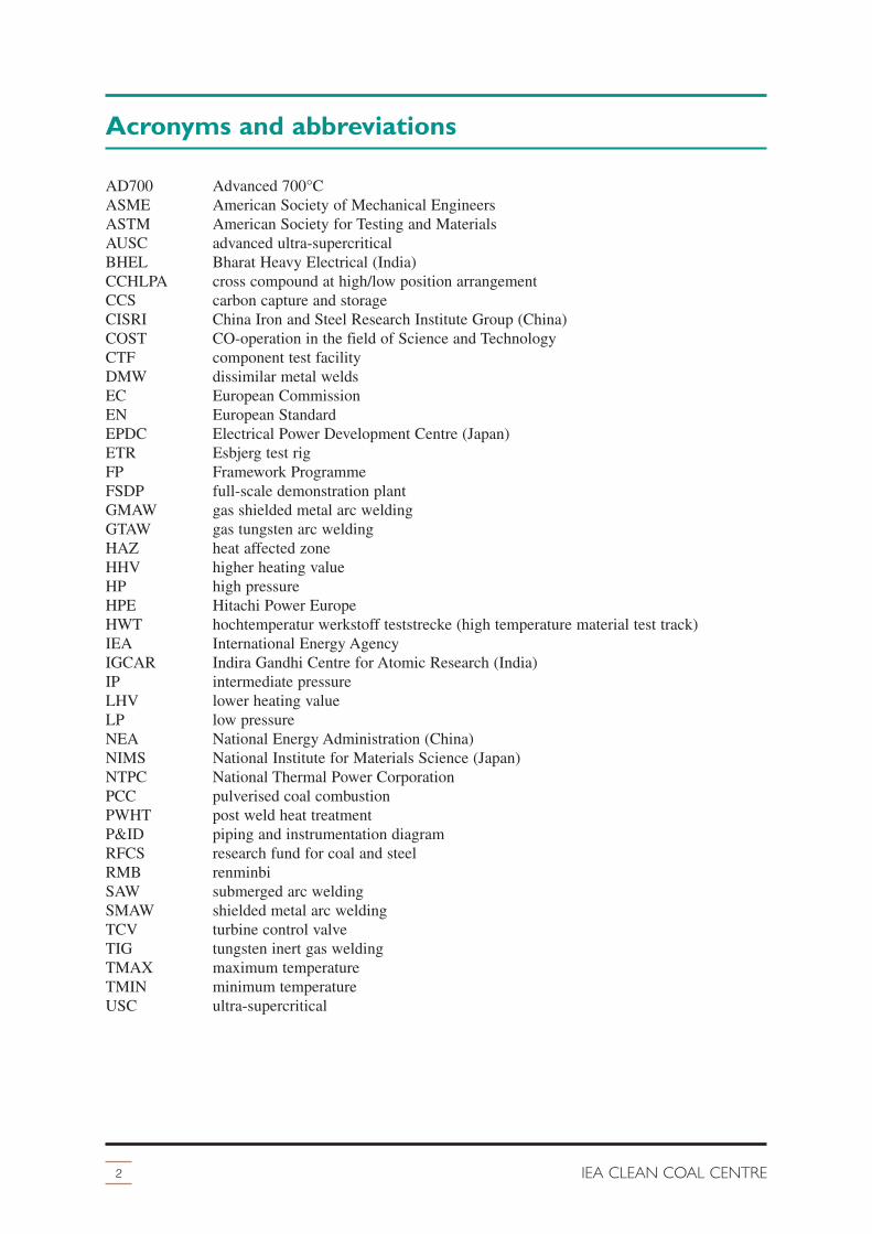
Acronyms and abbreviations
2 IEA CLEAN COAL CENTRE
AD700 Advanced 700°CASME American Society of Mechanical EngineersASTM American Society for Testing and MaterialsAUSC advanced ultra-supercriticalBHEL Bharat Heavy Electrical (India)CCHLPA cross compound at high/low position arrangementCCS carbon capture and storageCISRI China Iron and Steel Research Institute Group (China)COST CO-operation in the field of Science and TechnologyCTF component test facilityDMW dissimilar metal weldsEC European CommissionEN European StandardEPDC Electrical Power Development Centre (Japan)ETR Esbjerg test rigFP Framework ProgrammeFSDP full-scale demonstration plantGMAW gas shielded metal arc weldingGTAW gas tungsten arc weldingHAZ heat affected zoneHHV higher heating valueHP high pressureHPE Hitachi Power EuropeHWT hochtemperatur werkstoff teststrecke (high temperature material test track)IEA International Energy AgencyIGCAR Indira Gandhi Centre for Atomic Research (India)IP intermediate pressureLHV lower heating valueLP low pressureNEA National Energy Administration (China)NIMS National Institute for Materials Science (Japan)NTPC National Thermal Power CorporationPCC pulverised coal combustionPWHT post weld heat treatmentP&ID piping and instrumentation diagramRFCS research fund for coal and steel RMB renminbiSAW submerged arc weldingSMAW shielded metal arc weldingTCV turbine control valveTIG tungsten inert gas weldingTMAX maximum temperatureTMIN minimum temperatureUSC ultra-supercritical

Contents
3Status of advanced ultra-supercritical pulverised coal technology
Acronyms and abbreviations . . . . . . . . . . . . . . . . . . . . . . . . . . . . . . . . . . . . . . . . . . . . . . . . 2
Contents. . . . . . . . . . . . . . . . . . . . . . . . . . . . . . . . . . . . . . . . . . . . . . . . . . . . . . . . . . . . . . . . 3
1 Introduction . . . . . . . . . . . . . . . . . . . . . . . . . . . . . . . . . . . . . . . . . . . . . . . . . . . . . . . . . 5
2 Materials in PCC plant . . . . . . . . . . . . . . . . . . . . . . . . . . . . . . . . . . . . . . . . . . . . . . . . . 72.1 Carnot cycle . . . . . . . . . . . . . . . . . . . . . . . . . . . . . . . . . . . . . . . . . . . . . . . . . . . . . 72.2 Damage mechanisms . . . . . . . . . . . . . . . . . . . . . . . . . . . . . . . . . . . . . . . . . . . . . . 8
2.2.1 Chemical attack. . . . . . . . . . . . . . . . . . . . . . . . . . . . . . . . . . . . . . . . . . . . . 82.2.2 Stress . . . . . . . . . . . . . . . . . . . . . . . . . . . . . . . . . . . . . . . . . . . . . . . . . . . . . 9
2.3 Candidate materials. . . . . . . . . . . . . . . . . . . . . . . . . . . . . . . . . . . . . . . . . . . . . . . 112.4 Material standards. . . . . . . . . . . . . . . . . . . . . . . . . . . . . . . . . . . . . . . . . . . . . . . . 112.5 Welding . . . . . . . . . . . . . . . . . . . . . . . . . . . . . . . . . . . . . . . . . . . . . . . . . . . . . . . . 122.6 Coatings . . . . . . . . . . . . . . . . . . . . . . . . . . . . . . . . . . . . . . . . . . . . . . . . . . . . . . . 142.7 Economics of AUSC technology . . . . . . . . . . . . . . . . . . . . . . . . . . . . . . . . . . . . 14
3 European Union . . . . . . . . . . . . . . . . . . . . . . . . . . . . . . . . . . . . . . . . . . . . . . . . . . . . . 153.1 Financing and co-ordination initiatives . . . . . . . . . . . . . . . . . . . . . . . . . . . . . . . 15
3.1.1 EMAX . . . . . . . . . . . . . . . . . . . . . . . . . . . . . . . . . . . . . . . . . . . . . . . . . . . . 163.1.2 COORETEC . . . . . . . . . . . . . . . . . . . . . . . . . . . . . . . . . . . . . . . . . . . . . . 163.1.3 Horizon 2020 . . . . . . . . . . . . . . . . . . . . . . . . . . . . . . . . . . . . . . . . . . . . . 16
3.2 COST . . . . . . . . . . . . . . . . . . . . . . . . . . . . . . . . . . . . . . . . . . . . . . . . . . . . . . . . . 163.3 KOMET 650 . . . . . . . . . . . . . . . . . . . . . . . . . . . . . . . . . . . . . . . . . . . . . . . . . . . . 163.4 AD700-1 . . . . . . . . . . . . . . . . . . . . . . . . . . . . . . . . . . . . . . . . . . . . . . . . . . . . . . . 173.5 AD700-2 . . . . . . . . . . . . . . . . . . . . . . . . . . . . . . . . . . . . . . . . . . . . . . . . . . . . . . . 183.6 AD700-3 . . . . . . . . . . . . . . . . . . . . . . . . . . . . . . . . . . . . . . . . . . . . . . . . . . . . . . . 18
3.6.1 COMTES 700 . . . . . . . . . . . . . . . . . . . . . . . . . . . . . . . . . . . . . . . . . . . . . 193.6.2 TCV. . . . . . . . . . . . . . . . . . . . . . . . . . . . . . . . . . . . . . . . . . . . . . . . . . . . . 213.6.3 ETR . . . . . . . . . . . . . . . . . . . . . . . . . . . . . . . . . . . . . . . . . . . . . . . . . . . . . 21
3.7 AD700-4 . . . . . . . . . . . . . . . . . . . . . . . . . . . . . . . . . . . . . . . . . . . . . . . . . . . . . . . 213.7.1 NRWPP700 . . . . . . . . . . . . . . . . . . . . . . . . . . . . . . . . . . . . . . . . . . . . . . . 213.7.2 E.ON 50+ . . . . . . . . . . . . . . . . . . . . . . . . . . . . . . . . . . . . . . . . . . . . . . . . 23
3.8 MARCKO DE2. . . . . . . . . . . . . . . . . . . . . . . . . . . . . . . . . . . . . . . . . . . . . . . . . . 243.9 MARCKO 700 . . . . . . . . . . . . . . . . . . . . . . . . . . . . . . . . . . . . . . . . . . . . . . . . . . 243.10HWT I . . . . . . . . . . . . . . . . . . . . . . . . . . . . . . . . . . . . . . . . . . . . . . . . . . . . . . . . . 243.11 Post AD700 . . . . . . . . . . . . . . . . . . . . . . . . . . . . . . . . . . . . . . . . . . . . . . . . . . . . . 253.12COMTES+ . . . . . . . . . . . . . . . . . . . . . . . . . . . . . . . . . . . . . . . . . . . . . . . . . . . . . 25
3.12.1 HWT II . . . . . . . . . . . . . . . . . . . . . . . . . . . . . . . . . . . . . . . . . . . . . . . . . . 253.12.2 ENCIO . . . . . . . . . . . . . . . . . . . . . . . . . . . . . . . . . . . . . . . . . . . . . . . . . . 26
3.13NextGenPower . . . . . . . . . . . . . . . . . . . . . . . . . . . . . . . . . . . . . . . . . . . . . . . . . . 273.14MACPLUS . . . . . . . . . . . . . . . . . . . . . . . . . . . . . . . . . . . . . . . . . . . . . . . . . . . . . 273.15 IMPACT . . . . . . . . . . . . . . . . . . . . . . . . . . . . . . . . . . . . . . . . . . . . . . . . . . . . . . . 283.16KMM-VIN WG2. . . . . . . . . . . . . . . . . . . . . . . . . . . . . . . . . . . . . . . . . . . . . . . . . 28
3.16.1 EBW . . . . . . . . . . . . . . . . . . . . . . . . . . . . . . . . . . . . . . . . . . . . . . . . . . . . 293.16.2 MARBN . . . . . . . . . . . . . . . . . . . . . . . . . . . . . . . . . . . . . . . . . . . . . . . . . 293.16.3 Z Ultra. . . . . . . . . . . . . . . . . . . . . . . . . . . . . . . . . . . . . . . . . . . . . . . . . . . 29
3.17Rafako . . . . . . . . . . . . . . . . . . . . . . . . . . . . . . . . . . . . . . . . . . . . . . . . . . . . . . . . . 293.18 Summary . . . . . . . . . . . . . . . . . . . . . . . . . . . . . . . . . . . . . . . . . . . . . . . . . . . . . . . 30

4 USA . . . . . . . . . . . . . . . . . . . . . . . . . . . . . . . . . . . . . . . . . . . . . . . . . . . . . . . . . . . . . . 314.1 Boiler. . . . . . . . . . . . . . . . . . . . . . . . . . . . . . . . . . . . . . . . . . . . . . . . . . . . . . . . . . 31
4.1.1 Task 1: Conceptual design . . . . . . . . . . . . . . . . . . . . . . . . . . . . . . . . . . . 314.1.2 Task 1: Economic analysis . . . . . . . . . . . . . . . . . . . . . . . . . . . . . . . . . . . 324.1.3 Task 2: Mechanical properties . . . . . . . . . . . . . . . . . . . . . . . . . . . . . . . . 334.1.4 Task 3: Steamside oxidation . . . . . . . . . . . . . . . . . . . . . . . . . . . . . . . . . . 334.1.5 Task 4: Fireside corrosion. . . . . . . . . . . . . . . . . . . . . . . . . . . . . . . . . . . . 344.1.6 Task 5: Welding. . . . . . . . . . . . . . . . . . . . . . . . . . . . . . . . . . . . . . . . . . . . 354.1.7 Task 6: Fabricability . . . . . . . . . . . . . . . . . . . . . . . . . . . . . . . . . . . . . . . . 354.1.8 Task 8: Material standards . . . . . . . . . . . . . . . . . . . . . . . . . . . . . . . . . . . 36
4.2 Steam turbine . . . . . . . . . . . . . . . . . . . . . . . . . . . . . . . . . . . . . . . . . . . . . . . . . . . 364.3 Candidate materials. . . . . . . . . . . . . . . . . . . . . . . . . . . . . . . . . . . . . . . . . . . . . . . 374.4 CTF and FSDP . . . . . . . . . . . . . . . . . . . . . . . . . . . . . . . . . . . . . . . . . . . . . . . . . . 374.5 Topping cycle . . . . . . . . . . . . . . . . . . . . . . . . . . . . . . . . . . . . . . . . . . . . . . . . . . . 374.6 Summary . . . . . . . . . . . . . . . . . . . . . . . . . . . . . . . . . . . . . . . . . . . . . . . . . . . . . . . 38
5 Japan . . . . . . . . . . . . . . . . . . . . . . . . . . . . . . . . . . . . . . . . . . . . . . . . . . . . . . . . . . . . . . 395.1 Chemical and mechanical tests . . . . . . . . . . . . . . . . . . . . . . . . . . . . . . . . . . . . . . 39
5.1.1 Fireside corrosion . . . . . . . . . . . . . . . . . . . . . . . . . . . . . . . . . . . . . . . . . . 395.1.2 Steamside oxidation . . . . . . . . . . . . . . . . . . . . . . . . . . . . . . . . . . . . . . . . 40
5.2 New materials . . . . . . . . . . . . . . . . . . . . . . . . . . . . . . . . . . . . . . . . . . . . . . . . . . . 405.2.1 FENIX700. . . . . . . . . . . . . . . . . . . . . . . . . . . . . . . . . . . . . . . . . . . . . . . . 405.2.2 USC141. . . . . . . . . . . . . . . . . . . . . . . . . . . . . . . . . . . . . . . . . . . . . . . . . . 415.2.3 USC800MOD . . . . . . . . . . . . . . . . . . . . . . . . . . . . . . . . . . . . . . . . . . . . . 41
5.3 Steels for 650°C USC technology . . . . . . . . . . . . . . . . . . . . . . . . . . . . . . . . . . . 415.4 CTF and FSDP . . . . . . . . . . . . . . . . . . . . . . . . . . . . . . . . . . . . . . . . . . . . . . . . . . 415.5 Summary . . . . . . . . . . . . . . . . . . . . . . . . . . . . . . . . . . . . . . . . . . . . . . . . . . . . . . . 41
6 China. . . . . . . . . . . . . . . . . . . . . . . . . . . . . . . . . . . . . . . . . . . . . . . . . . . . . . . . . . . . . . 446.1 Ministry of Science and Technology . . . . . . . . . . . . . . . . . . . . . . . . . . . . . . . . . 446.2 Material special workgroup . . . . . . . . . . . . . . . . . . . . . . . . . . . . . . . . . . . . . . . . 466.3 NEA . . . . . . . . . . . . . . . . . . . . . . . . . . . . . . . . . . . . . . . . . . . . . . . . . . . . . . . . . . 46
6.3.1 CTF-700 and FSDP . . . . . . . . . . . . . . . . . . . . . . . . . . . . . . . . . . . . . . . . 466.4 Future projects . . . . . . . . . . . . . . . . . . . . . . . . . . . . . . . . . . . . . . . . . . . . . . . . . . 476.5 Plant configuration . . . . . . . . . . . . . . . . . . . . . . . . . . . . . . . . . . . . . . . . . . . . . . . 476.6 Summary . . . . . . . . . . . . . . . . . . . . . . . . . . . . . . . . . . . . . . . . . . . . . . . . . . . . . . . 47
7 Russia . . . . . . . . . . . . . . . . . . . . . . . . . . . . . . . . . . . . . . . . . . . . . . . . . . . . . . . . . . . . . 49
8 India . . . . . . . . . . . . . . . . . . . . . . . . . . . . . . . . . . . . . . . . . . . . . . . . . . . . . . . . . . . . . . 50
9 Conclusions . . . . . . . . . . . . . . . . . . . . . . . . . . . . . . . . . . . . . . . . . . . . . . . . . . . . . . . . 51
10 References . . . . . . . . . . . . . . . . . . . . . . . . . . . . . . . . . . . . . . . . . . . . . . . . . . . . . . . . . 54
4 IEA CLEAN COAL CENTRE
1 Introduction
5Status of advanced ultra-supercritical pulverised coal technology
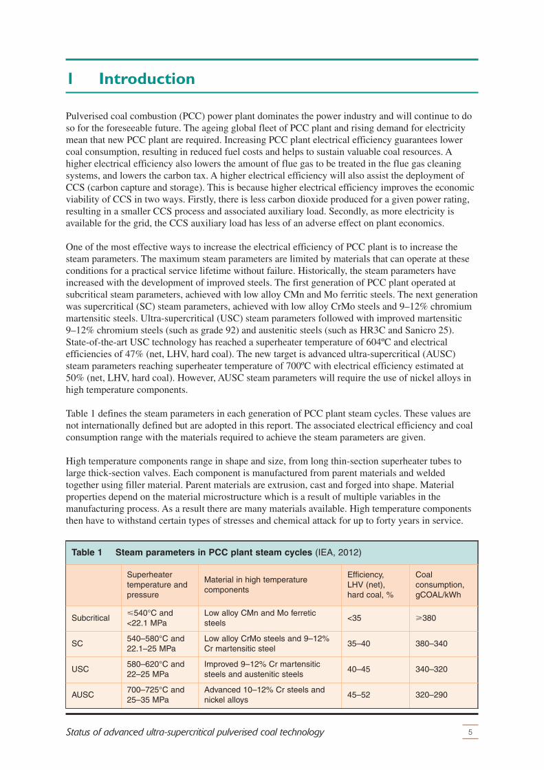
Pulverised coal combustion (PCC) power plant dominates the power industry and will continue to doso for the foreseeable future. The ageing global fleet of PCC plant and rising demand for electricitymean that new PCC plant are required. Increasing PCC plant electrical efficiency guarantees lowercoal consumption, resulting in reduced fuel costs and helps to sustain valuable coal resources. Ahigher electrical efficiency also lowers the amount of flue gas to be treated in the flue gas cleaningsystems, and lowers the carbon tax. A higher electrical efficiency will also assist the deployment ofCCS (carbon capture and storage). This is because higher electrical efficiency improves the economicviability of CCS in two ways. Firstly, there is less carbon dioxide produced for a given power rating,resulting in a smaller CCS process and associated auxiliary load. Secondly, as more electricity isavailable for the grid, the CCS auxiliary load has less of an adverse effect on plant economics.
One of the most effective ways to increase the electrical efficiency of PCC plant is to increase thesteam parameters. The maximum steam parameters are limited by materials that can operate at theseconditions for a practical service lifetime without failure. Historically, the steam parameters haveincreased with the development of improved steels. The first generation of PCC plant operated atsubcritical steam parameters, achieved with low alloy CMn and Mo ferritic steels. The next generationwas supercritical (SC) steam parameters, achieved with low alloy CrMo steels and 9–12% chromiummartensitic steels. Ultra-supercritical (USC) steam parameters followed with improved martensitic9–12% chromium steels (such as grade 92) and austenitic steels (such as HR3C and Sanicro 25).State-of-the-art USC technology has reached a superheater temperature of 604ºC and electricalefficiencies of 47% (net, LHV, hard coal). The new target is advanced ultra-supercritical (AUSC)steam parameters reaching superheater temperature of 700ºC with electrical efficiency estimated at50% (net, LHV, hard coal). However, AUSC steam parameters will require the use of nickel alloys inhigh temperature components.
Table 1 defines the steam parameters in each generation of PCC plant steam cycles. These values arenot internationally defined but are adopted in this report. The associated electrical efficiency and coalconsumption range with the materials required to achieve the steam parameters are given.
High temperature components range in shape and size, from long thin-section superheater tubes tolarge thick-section valves. Each component is manufactured from parent materials and weldedtogether using filler material. Parent materials are extrusion, cast and forged into shape. Materialproperties depend on the material microstructure which is a result of multiple variables in themanufacturing process. As a result there are many materials available. High temperature componentsthen have to withstand certain types of stresses and chemical attack for up to forty years in service.
Table 1 Steam parameters in PCC plant steam cycles (IEA, 2012)
Superheatertemperature andpressure
Material in high temperaturecomponents
Efficiency, LHV (net),hard coal, %
Coalconsumption,gCOAL/kWh
Subcritical�540°C and<22.1 MPa
Low alloy CMn and Mo ferreticsteels
<35 �380
SC540–580°C and22.1–25 MPa
Low alloy CrMo steels and 9–12%Cr martensitic steel
35–40 380–340
USC580–620°C and22–25 MPa
Improved 9–12% Cr martensiticsteels and austenitic steels
40–45 340–320
AUSC700–725°C and25–35 MPa
Advanced 10–12% Cr steels andnickel alloys
45–52 320–290
Superheater manufacture involves extruding several materials into long thin-section tubes, which arewelded together with shallow welds. Superheaters are exposed to fireside corrosion, steamsideoxidation, static loads and fluctuating thermal gradients, which cause creep and fatigue damagerespectively. A contrasting example is a steam turbine valve. Parent materials are forged or cast intothick-section shapes and welded together with deep welds. Steam turbine valves require highresistance to steamside oxidation and fatigue damage.
Developing AUSC technology will require an extensive and complex materials research programme,lasting over ten years at a substantial cost with high technical risk. Major industries haveacknowledged that it is not possible to develop AUSC technology alone. Consortia of utilities,manufacturers, research establishments are required to combine their individual strengths andresources in order to solve the technical issues to expedite AUSC technology.
Furthermore, developing AUSC technology is economically risky for investors. In some casesfinancial support has been provided by government bodies in order to mitigate the financial risk.There are such material research programmes in the USA, EU, Russia, Japan, China and India. Thisreport reviews developments and status of the major material research programmes for AUSC)pulverised coal technology.
Osgerby (2007) estimates that, for a specific component fabricated from new materials, a typical hightemperature materials research programme takes roughly twelve years. The programme will consist ofthe following stages:� Investigation of trial materials (two years): Includes creep rupture testing to at least
10,000 hours;� Prototype component manufacture from the best trial material (oneyear): This stage is
essential to demonstrate that the material can be manufactured and welded into large-scalecomponents without problems arising from microstructure change (such as excessive chemicalsegregation or grain size control). A thorough inspection routine of large-scale components mustbe demonstrated;
� Characterisation of the prototype (four years): This typically includes long-term creep rupturetesting from at least 30,000 to 100,000 hours (roughly 3½–11 years), low cycle fatigue testingand cycle hold testing. Other investigations that may be carried out include the influence oflong-term ageing on tensile and impact strength, fracture toughness and cracking properties.Steamside oxidation and fireside corrosion rates must be assessed;
� Commercial component (1 year): Launch as commercial material and gain first purchase order;� Test commercial products to establish scatter band of properties (four years): Variations in
component properties are typically of the order of ±20%. Knowledge of this scatter band and theposition of the first prototype within it are required to exploit fully the properties demonstrated ina single prototype.
6 IEA CLEAN COAL CENTRE
Introduction
2 Materials in PCC plant
7Status of advanced ultra-supercritical pulverised coal technology
This chapter provides background information on the use of high temperature materials in pulverisedcoal technology. Section 2.1 explains how increasing superheater steam temperature results inincreased electrical efficiency. Section 2.2 explains how high temperature materials are damaged inPCC plant. Section 2.3 and Section 2.4 list the candidate materials that are required for AUSCtechnology and explain the materials standards involved. Sections 2.5 and 2.6 briefly explain thewelding process and concept of coatings respectively. Section 2.7 describes economics involved inAUSC technology.
2.1 Carnot cycle
PCC plant transfer heat energy from the boiler to the steam turbine via the steam cycle. The steamcycle operates under the thermodynamic principle of the Carnot cycle (specifically the Rankine cyclewhen water is used as the working fluid). The Carnot cycle efficiency is proportional to the equationTMAX–TMIN)/TMAX, where TMAX is the maximum temperature and TMIN is the minimum temperature,both measured in kelvin. Therefore, to improve the Carnot cycle efficiency the difference betweenTMIN and TMAX must be increased (Modern Power Systems, 2008; Nalbandian, 2008). Increasing boththe superheater and reheater temperatures by 20°C equates to an increase of roughly 1% point in netefficiency (National Coal Council, 2007).
TMAX is found in the superheater, main steam pipework and valves, and the high pressure (HP)turbine. TMAX is limited by materials that can operate in these components at these temperatures for apractical length of time without failure.
TMIN is dependent on the cooling water source, which can be river water or sea water. The amount ofcooling available depends on the temperature of the cooling water which varies geographically. APCC plant in Scandinavia that is cooled by sea water from the Baltic Sea will have greater coolingcapacity compared to air cooled plant in the Karoo region of South Africa. In Europe, a PCC plantwith sea water cooling has 1.5–2% points additional electrical efficiency than the same PCC plantlocated inland using river water cooling (recirculated in cooling towers) (VGB, 2012b). Thus, theminimum temperature is constrained geographically.
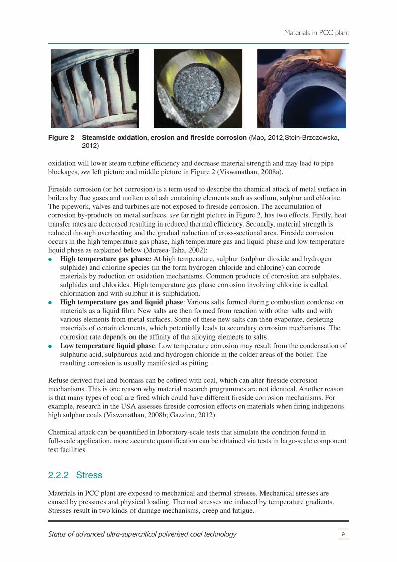
Increasing TMAX reduces losses to what is known as the Carnotisation gap. The Carnotisation gap isloss in efficiency due to thermodynamic incompleteness of the Carnot cycle. The Carnotisation gap islarge at low temperatures. For example, 10% of electrical efficiency is lost to the Carnotisation gapwhen TMAX is 600°C, and can be reduced significantly when TMAX exceeds 900°C. This concept isrepresented graphically in Figure 1 as a plot of TMAX (°C) and related carbon dioxide emissions(gCO2/kWh) with efficiency – the numbers used are an average of the global values.
Other aspects of the electrical efficiency of PCC plant include the heating value of the coal-fired,auxiliary load and internal losses, andwhether it is single or double reheat and the method ofperformance measurement. It is also important that efficiency is calculated on the same heating valuebasis, which is generally the lower heating value (LHV). Efficiency measured on a higher heatingvalue (HHV) basis can be nearly 2% points lower than a LHV basis for bituminous coals (10–12%moisture content) and 6% points lower for many lignite coals (Henderson, 2013). Figure 1 showssome state-of-the-art PCC plant operating in 2013. Although reheat temperatures are higher thanTMAX, the steam has significantly lower pressure and therefore much less energy. Figure 1 illustratesthe efficiency gain of a double reheat PCC plant.
Increasing efficiency by increasing the maximum steam pressure is not as beneficial as increasing

TMAX for two reasons. Firstly, increasing TMAX from 600°C to 700°C will result in an efficiency riseof 2.2%, whereas increasing the pressure from 25 MPa to 35 MPa results in an efficiency rise of 0.8%(Mao, 2012). Secondly, higher maximum pressures require thicker-section components. This limitsthe rate of heat transfer, leading to longer load change times, which are detrimental for cyclicoperation.
Net efficiency loss to auxiliary load and internal losses together are known as the component gap. Thecomponent gap can no longer be significantly improved as it has reached a point of diminishingreturns; this loss accounts for approximately 10% net efficiency when TMAX is 600°C (Modern PowerSystems, 2008).
To summarise, as TMIN is constrained geographically and the component gap is largely closed, thesingle most effective way to increase the net electrical efficiency of PCC plant is to increase TMAX.
2.2 Damage mechanisms
Materials last for a finite time in an operating PCC plant. Materials are gradually degraded bychemical attack, in the form of fireside corrosion and steamside oxidation, which lowers the materialstrength. At the same time these materials are exposed to mechanical stresses, induced by physicalloads or thermal gradients, which deform the material. Ultimately, the combination of chemical attackand mechanical stresses on materials in service will result in material failure. The followingsub-sections will expand on chemical attack and stress.
2.2.1 Chemical attack
Steamside oxidation is the oxidation of metal surfaces exposed to the steam in the steam loop; thiswill be most prevalent in higher temperature locations, such as pipes, tubes, valves and steam turbines.Steamside oxidation consists of three stages. Firstly, oxide scale builds up causing materials tooverheat, which decreases material strength. Secondly, the oxide scale eventually exfoliates, graduallyreducing the materials cross-sectional area, which again decreases material strength. Finally, the oxidescale fragments and erodes the entire steam loop, further decreasing strength. In short, steamside
8 IEA CLEAN COAL CENTRE
Materials in PCC plant
49
48
47
46
45
38
685
Superheater steam temperature, °C
Ele
ctric
al e
ffici
ency
, LH
V, n
et
50
51
665645625605585565545 705
43
42
41
40
39
44
830820810800790
660
840850
770760750740730
780
Car
bon
dio
xid
e em
issi
ons,
gC
O2/
kWh
710700690680670
720Isogo 2, Japan (600/620/25)
Waigaoqiao 3, China (600/600/25.86)
Nordjylland 3, Denmark (582/580/580/29)
Torrevaldaliga, Italy (604/612/25)
Niederaussem K, Germany (580/600/27.5) lignite
Figure 1 Relationship between steam temperature and electrical efficiency (IEA Clean CoalCentre, 2012; IEA, 2012, VGB 2012; Mao, 2012; Gibbons, 2013)
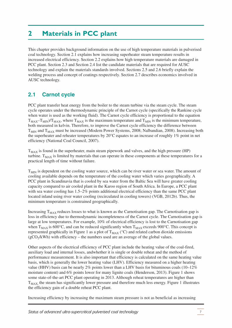
oxidation will lower steam turbine efficiency and decrease material strength and may lead to pipeblockages, see left picture and middle picture in Figure 2 (Viswanathan, 2008a).
Fireside corrosion (or hot corrosion) is a term used to describe the chemical attack of metal surface inboilers by flue gases and molten coal ash containing elements such as sodium, sulphur and chlorine.The pipework, valves and turbines are not exposed to fireside corrosion. The accumulation ofcorrosion by-products on metal surfaces, see far right picture in Figure 2, has two effects. Firstly, heattransfer rates are decreased resulting in reduced thermal efficiency. Secondly, material strength isreduced through overheating and the gradual reduction of cross-sectional area. Fireside corrosionoccurs in the high temperature gas phase, high temperature gas and liquid phase and low temperatureliquid phase as explained below (Moreea-Taha, 2002):� High temperature gas phase: At high temperature, sulphur (sulphur dioxide and hydrogen
sulphide) and chlorine species (in the form hydrogen chloride and chlorine) can corrodematerials by reduction or oxidation mechanisms. Common products of corrosion are sulphates,sulphides and chlorides. High temperature gas phase corrosion involving chlorine is calledchlorination and with sulphur it is sulphidation.
� High temperature gas and liquid phase: Various salts formed during combustion condense onmaterials as a liquid film. New salts are then formed from reaction with other salts and withvarious elements from metal surfaces. Some of these new salts can then evaporate, depletingmaterials of certain elements, which potentially leads to secondary corrosion mechanisms. Thecorrosion rate depends on the affinity of the alloying elements to salts.
� Low temperature liquid phase: Low temperature corrosion may result from the condensation ofsulphuric acid, sulphurous acid and hydrogen chloride in the colder areas of the boiler. Theresulting corrosion is usually manifested as pitting.
Refuse derived fuel and biomass can be cofired with coal, which can alter fireside corrosionmechanisms. This is one reason why material research programmes are not identical. Another reasonis that many types of coal are fired which could have different fireside corrosion mechanisms. Forexample, research in the USA assesses fireside corrosion effects on materials when firing indigenoushigh sulphur coals (Viswanathan, 2008b; Gazzino, 2012).
Chemical attack can be quantified in laboratory-scale tests that simulate the condition found infull-scale application, more accurate quantification can be obtained via tests in large-scale componenttest facilities.
2.2.2 Stress
Materials in PCC plant are exposed to mechanical and thermal stresses. Mechanical stresses arecaused by pressures and physical loading. Thermal stresses are induced by temperature gradients.Stresses result in two kinds of damage mechanisms, creep and fatigue.
9Status of advanced ultra-supercritical pulverised coal technology
Materials in PCC plant
Figure 2 Steamside oxidation, erosion and fireside corrosion (Mao, 2012,Stein-Brzozowska,2012)

Creep is time-dependent deformation of material with time due to constant stress. Creep damage isseen as strain in the material, internal damage, cavitation and cracks on the metal surface and willterminate in rupture. Creep damage is measured as a percentage material affected that has occurredwithin the projected life of the material. Turbine blades have to withstand creep damage, as contactwith turbine casing would result in catastrophic failure. Fatigue is caused by cyclic stresses and canresult in internal cracking. Generally, cyclic stresses have increased with more vigorous cyclicoperation in PCC plant over the last two decades (due to market forces and the use of renewableenergy). Creep-fatigue is the combined interaction of creep and fatigue. Ultimately, a complexinteraction between chemical attack, thermal and mechanical stresses will cause material failure(Viswanathan, 2008a; Kranzmann and others, 2012; Starkey, 2013).
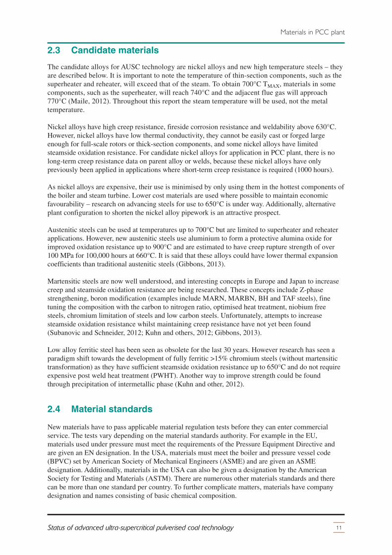
In PCC plant, creep damage is affected by varying stresses – the number of possiblestress-temperature-time combinations is infinite. Creep rupture tests are used to determine the timetaken of a material to rupture under a fixed static tensile load (0–500 MPa) at a constant certaintemperature (500–800°C). Short-term creep rupture tests are in the region of 10,000 hours(14 months) long-term creep rupture tests are 100,000 hours long (11½ years). Data can be plotted asa log of stress against a log of time to which a best fit curve for a certain temperature is obtained. Thisbest fit curve for a certain temperature can be extrapolated to predict stress to failure for longer times.An alternative way of plotting these results is with a log of stress against temperature for a certaintime to rupture (such as 100,000 hours). Again, a best fit curve for a certain time to rupture can bedrawn, extrapolated and used to predict temperature to failure at a certain stress (NDT ResourceCenter, 2013). Figure 3 shows results from creep rupture tests at 100,000 hours for different materials.In these tests, PCC plant materials have to be able to withstand at least 100 MPa for 100,000 hours atthe required temperature. This requirement rules out the use of steels above 700°C, only nickel alloyshave sufficient creep rupture strength (Romanosky, 2012).
10 IEA CLEAN COAL CENTRE
Materials in PCC plant
Stre
ss, t
hous
and
pou
nd p
er s
qua
re in
ch
100
80
60
40
Temperature, °C
Stre
ss, M
Pa
300
500
nickel-based alloys
750700650600550 800
30
10
8
6
50
70
Haynes 282Inconel 740
Standard 617
CCA 617
Haynes 230
minimum desiredstrength (100 MPa) at
application temperature
9-12% CrMartensitic steels
Austenitic steels
steels = USC620°C
solid soln’ = AUSC~700°C
age hardenable = AUSC760°C
1400130012001100
Temperature, °F
Figure 3 100,000 hour creep rupture tests (Romanosky, 2012)
2.3 Candidate materials
The candidate alloys for AUSC technology are nickel alloys and new high temperature steels – theyare described below. It is important to note the temperature of thin-section components, such as thesuperheater and reheater, will exceed that of the steam. To obtain 700°C TMAX, materials in somecomponents, such as the superheater, will reach 740°C and the adjacent flue gas will approach770°C (Maile, 2012). Throughout this report the steam temperature will be used, not the metaltemperature.
Nickel alloys have high creep resistance, fireside corrosion resistance and weldability above 630°C.However, nickel alloys have low thermal conductivity, they cannot be easily cast or forged largeenough for full-scale rotors or thick-section components, and some nickel alloys have limitedsteamside oxidation resistance. For candidate nickel alloys for application in PCC plant, there is nolong-term creep resistance data on parent alloy or welds, because these nickel alloys have onlypreviously been applied in applications where short-term creep resistance is required (1000 hours).
As nickel alloys are expensive, their use is minimised by only using them in the hottest components ofthe boiler and steam turbine. Lower cost materials are used where possible to maintain economicfavourability – research on advancing steels for use to 650°C is under way. Additionally, alternativeplant configuration to shorten the nickel alloy pipework is an attractive prospect.
Austenitic steels can be used at temperatures up to 700°C but are limited to superheater and reheaterapplications. However, new austenitic steels use aluminium to form a protective alumina oxide forimproved oxidation resistance up to 900°C and are estimated to have creep rupture strength of over100 MPa for 100,000 hours at 660°C. It is said that these alloys could have lower thermal expansioncoefficients than traditional austenitic steels (Gibbons, 2013).
Martensitic steels are now well understood, and interesting concepts in Europe and Japan to increasecreep and steamside oxidation resistance are being researched. These concepts include Z-phasestrengthening, boron modification (examples include MARN, MARBN, BH and TAF steels), finetuning the composition with the carbon to nitrogen ratio, optimised heat treatment, niobium freesteels, chromium limitation of steels and low carbon steels. Unfortunately, attempts to increasesteamside oxidation resistance whilst maintaining creep resistance have not yet been found(Subanovic and Schneider, 2012; Kuhn and others, 2012; Gibbons, 2013).
Low alloy ferritic steel has been seen as obsolete for the last 30 years. However research has seen aparadigm shift towards the development of fully ferritic >15% chromium steels (without martensitictransformation) as they have sufficient steamside oxidation resistance up to 650°C and do not requireexpensive post weld heat treatment (PWHT). Another way to improve strength could be foundthrough precipitation of intermetallic phase (Kuhn and other, 2012).
2.4 Material standards
New materials have to pass applicable material regulation tests before they can enter commercialservice. The tests vary depending on the material standards authority. For example in the EU,materials used under pressure must meet the requirements of the Pressure Equipment Directive andare given an EN designation. In the USA, materials must meet the boiler and pressure vessel code(BPVC) set by American Society of Mechanical Engineers (ASME) and are given an ASMEdesignation. Additionally, materials in the USA can also be given a designation by the AmericanSociety for Testing and Materials (ASTM). There are numerous other materials standards and therecan be more than one standard per country. To further complicate matters, materials have companydesignation and names consisting of basic chemical composition.
11Status of advanced ultra-supercritical pulverised coal technology
Materials in PCC plant
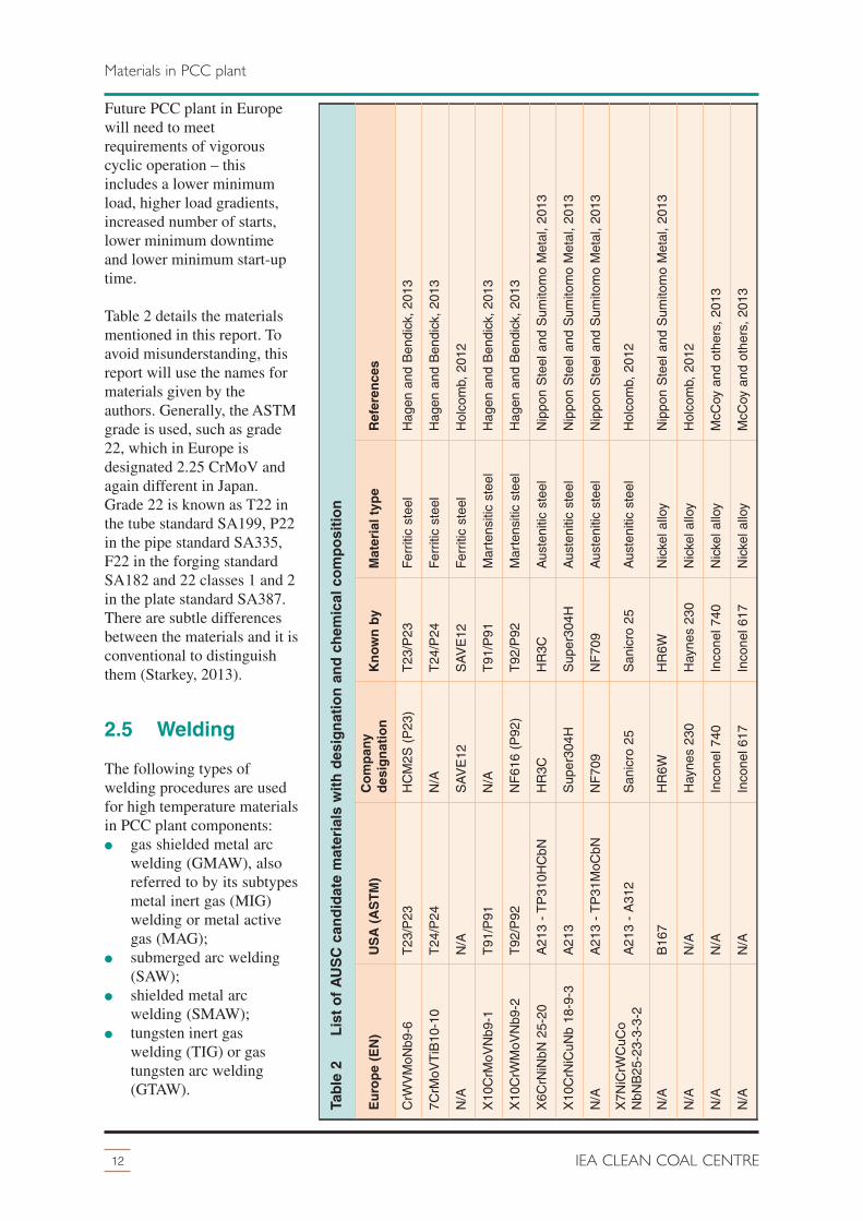
Future PCC plant in Europewill need to meetrequirements of vigorouscyclic operation – thisincludes a lower minimumload, higher load gradients,increased number of starts,lower minimum downtimeand lower minimum start-uptime.
Table 2 details the materialsmentioned in this report. Toavoid misunderstanding, thisreport will use the names formaterials given by theauthors. Generally, the ASTMgrade is used, such as grade22, which in Europe isdesignated 2.25 CrMoV andagain different in Japan.Grade 22 is known as T22 inthe tube standard SA199, P22in the pipe standard SA335,F22 in the forging standardSA182 and 22 classes 1 and 2in the plate standard SA387.There are subtle differencesbetween the materials and it isconventional to distinguishthem (Starkey, 2013).
2.5 Welding
The following types ofwelding procedures are usedfor high temperature materialsin PCC plant components:� gas shielded metal arc
welding (GMAW), alsoreferred to by its subtypesmetal inert gas (MIG)welding or metal activegas (MAG);
� submerged arc welding(SAW);
� shielded metal arcwelding (SMAW);
� tungsten inert gaswelding (TIG) or gastungsten arc welding(GTAW).
12 IEA CLEAN COAL CENTRE
Materials in PCC plant
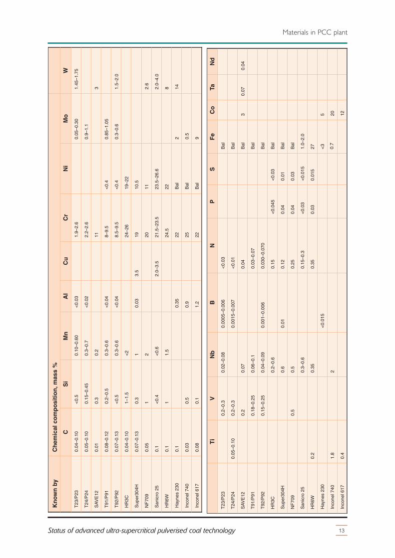
Table 2 List of AUSC candidate materials with designation and chemical composition
Europe (EN)
USA (ASTM)
Company
designation
Known by
Material type
References
CrW
VM
oNb9
-6T
23/P
23H
CM
2S (
P23
)T
23/P
23F
errit
ic s
teel
Hag
en a
nd B
endi
ck,
2013
7CrM
oVT
iB10
-10
T24
/P24
N/A
T24
/P24
Fer
ritic
ste
elH
agen
and
Ben
dick
, 20
13
N/A
N/A
SA
VE
12S
AV
E12
Fer
ritic
ste
elH
olco
mb,
201
2
X10
CrM
oVN
b9-1
T91
/P91
N/A
T91
/P91
Mar
tens
itic
stee
lH
agen
and
Ben
dick
, 20
13
X10
CrW
MoV
Nb9
-2T
92/P
92N
F61
6 (P
92)
T92
/P92
Mar
tens
itic
stee
lH
agen
and
Ben
dick
, 20
13
X6C
rNiN
bN 2
5-20
A21
3 -
TP
310H
CbN
HR
3CH
R3C
Aus
teni
tic s
teel
Nip
pon
Ste
el a
nd S
umito
mo
Met
al,
2013
X10
CrN
iCuN
b 18
-9-3
A21
3S
uper
304H
Sup
er30
4HA
uste
nitic
ste
elN
ippo
n S
teel
and
Sum
itom
o M
etal
, 20
13
N/A
A21
3 -
TP
31M
oCbN
NF
709
NF
709
Aus
teni
tic s
teel
Nip
pon
Ste
el a
nd S
umito
mo
Met
al,
2013
X7N
iCrW
CuC
oN
bNB
25-2
3-3-
3-2
A21
3 -
A31
2S
anic
ro 2
5S
anic
ro 2
5A
uste
nitic
ste
elH
olco
mb,
201
2
N/A
B16
7H
R6W
HR
6WN
icke
l allo
yN
ippo
n S
teel
and
Sum
itom
o M
etal
, 20
13
N/A
N/A
Hay
nes
230
Hay
nes
230
Nic
kel a
lloy
Hol
com
b, 2
012
N/A
N/A
Inco
nel 7
40In
cone
l 740
Nic
kel a
lloy
McC
oy a
nd o
ther
s, 2
013
N/A
N/A
Inco
nel 6
17In
cone
l 617
Nic
kel a
lloy
McC
oy a
nd o
ther
s, 2
013
13Status of advanced ultra-supercritical pulverised coal technology
Materials in PCC plant
Ti
VNb
BN
PS
Fe
Co
TaNd
T23
/P23
0.2–
0.3
0.02
–0.0
80.
0005
–0.0
06<
0.03
Bal
T24
/P24
0.05
–0.1
00.
2–0.
30.
0015
–0.0
07<
0.01
Bal
SA
VE
120.
20.
070.
04B
al3
0.07
0.04
T91
/P91
0.18
–0.2
50.
06–0
.10.
03–0
.07
Bal
T92
/P92
0.15
–0.2
50.
04–0
.09
0.00
1–0.
006
0.03
0–0.
070
Bal
HR
3C0.
2–0.
60.
15<
0.04
5<
0.03
Bal
Sup
er30
4H0.
60.
010.
120.
040.
01B
al
NF
709
0.5
0.5
0.25
0.04
0.03
Bal
San
icro
25
0.3–
0.6
0.15
–0.3
<0.
03<
0.01
51.
0–2.
0
HR
6W0.
20.
350.
350.
030.
015
27
Hay
nes
230
<0.
015
<3
5
Inco
nel 7
401.
82
0.7
20
Inco
nel 6
170.
412
Known by
Chemical composition, mass %
CSi
Mn
Al
Cu
Cr
Ni
Mo
W
T23
/P23
0.04
–0.1
0<
0.5
0.10
–0.6
0<
0.03
1.9–
2.6
0.05
–0.3
01.
45–1
.75
T24
/P24
0.05
–0.1
00.
15–0
.45
0.3–
0.7
<0.
022.
2–2.
60.
9–1.
1
SA
VE
120.
010.
30.
211
3
T91
/P91
0.08
–0.1
20.
2–0.
50.
3–0.
6<
0.04
8–9.
5<
0.4
0.85
–1.0
5
T92
/P92
0.07
–0.1
3<
0.5
0.3–
0.6
<0.
048.
5–9.
5<
0.4
0.3–
0.6
1.5–
2.0
HR
3C0.
04–0
.10
1–1.
5<
224
–26
19–2
2
Sup
er30
4H0.
07–0
.13
0.3
10.
033.
519
10.5
NF
709
0.05
12
2011
2.6
San
icro
25
0.1
<0.
4<
0.6
2.0–
3.5
21.5
–23.
523
.5–2
6.6
2.0–
4.0
HR
6W0.
11
1.5
24.5
228
Hay
nes
230
0.1
0.35
22B
al2
14
Inco
nel 7
400.
030.
50.
925
Bal
0.5
Inco
nel 6
170.
080.
11.
222
Bal
9
Welding can introduce internal stresses and undesirable changes to the microstructure in the heataffected zone (HAZ) of the parent material. Post weld heat treatment can be used reduce these internalstresses and prevent permanent microstructure changes caused by welding. The ratio of creep rupturestrength of the welded joint to the strength of the base metal is called the weld strength factor (WSF).In general, boilers require a WSF of 0.8–0.85 over 100,000 hours; nickel alloys in AUSC technologymay suffice with a lower WSF.
Dissimilar metal welds (DMW) are welds between two materials with different thermal coefficients ofexpansion. Thermal stress can cause DMW to crack and potentially rupture. The risk of cracking isgreater for thicker-section components. This is one of the reasons why austenitic steel is limited tosuperheater and reheater applications. The application of nickel alloys with steels in PCC plant mayincrease the risk of cracking at DMW (Stultz and Kitto 2005; Viswanathan, 2008a).
2.6 Coatings
Historically steels have been modified to improve resistance to chemical attack, however furthermodification has proven difficult. Fortunately there is an alternative route to improve resistance tochemical attack through the use of coatings (carbide/metallic spraying). Coatings can be applied onthe inside diameter surface for protection against steamside oxidation or on the outer diameter (OD)surface to combat the effects of fireside corrosion. If used, the reduced need for inherent resistance tochemical attack of materials will allow the use of lower cost materials and a radical change incomponent design and manufacturing process would be required, depending on the method of coatingapplication (Osgerby, 2007). Coating metals requires strict process control otherwise the coating maynot adhere. Coatings are not currently used in PCC plant and boiler manufactures have avoidedcoatings as they have failed to work in practice (Holmström 2012).
2.7 Economics of AUSC technology
The economic viability of AUSC technology depends on the efficiency, the capital cost (which isincreased through the use of nickel alloys), coal price and carbon tax. Although the capital cost isgreater, the operation, maintenance and fuel costs are reduced. Generally, AUSC steam parametersstart with superheater steam at 700°C as this is where use of nickel alloys is estimated to becomeeconomically favourable and technically viable.
The capital cost of nickel alloys depends on the price of raw materials and manufacturing. The rawmaterial cost represents roughly a third of the nickel alloy component cost – this cost depends onvariable trade price of nickel and other expensive alloying elements such as cobalt and molybdenum.The manufacturing cost of nickel alloys represents roughly two thirds of the nickel alloy componentcost – this is dependent on the amount of skilled labour available and manufacturing capacity.Advanced steels generally cost the same as the alloying element, and manufacturing techniques aresimilar.
Mao (2012) states that at current prices, and assuming a single reheat PCC plant, the cost of the mainand reheat piping in Inconel 617 will be forty-three times more expensive as using P92. Gierschnerand others (2012) say that components manufactured from nickel alloys are at least ten times moreexpensive than ferritic steel and five times more expensive than martensitic steel.
14 IEA CLEAN COAL CENTRE
Materials in PCC plant

3 European Union
15Status of advanced ultra-supercritical pulverised coal technology
The European Union (EU) has a deregulated power market, tight emission standards and hassubsidises renewable energy. Much of the readily available coal has been mined and the extraction ofgas from shale formations could potentially become a significant energy source. For these reasons,electricity from renewable sources and gas has increased and new build PCC plant in Europe are onlyrequired with the closure old PCC plant or nuclear power. Historically however, Europe has been atthe forefront of coal technology and still operates some of the most efficient and environmentallyclean PCC plant globally.
High temperature materials used in state-of the-art USC PCC plant have been developed largely inEurope and research continues. Figure 4 shows a Gantt chart of the high temperature material researchprogrammes in Europe accurate to 2013 with plans to 2026. The steel research programme COST ishighlighted in green and ended in 2008. The first high temperature materials research programmeAD700 started in 1998 and finished in 2011 is highlighted in red. AD700 continued in 2011 under thenames of COMTES+ (HWT II and ENCIO), NextGenPower and MACPLUS, they are planned tofinish in by 2017 and are highlighted in blue. Smaller projects, mostly based in Germany, arehighlighted in purple. The following sections of this chapter will first explain the co-ordination andfunding initiatives and then expand on the material research programmes and projects.
Year
2005
COST 501
COST 522
AD700-1A
AD700-1B
MARCKO DE 2
KOMET 650
AD700-2A
AD700-2B
COST 536
MARCKO 700
AD700-3: ETR
AD700-3: COMTES700
AD700-4: NRWPP700
AD700-4: E.ON50+
HWT I: phase 1
CRESTA
IMPACT
COMTES+: HWT II
COMTES+: ENCIO
NextGenPower
MACPLUS
HWT I: phase 2
FSDP: build
FSDP: operation
2026
1998
1999
2000
2001
2002
2003
2004
2011
2006
2007
2008
2009
2010
2013
2012
2016
2014
2015
2017
2020
2019
2022
2021
2025
2023
2024
2018
Figure 4 Gantt chart of the European research programme
3.1 Financing and co-ordination initiatives
High temperature materials research projects in Europe are co-ordinated and sometimes partlyfinanced by the European EMAX initiative or German COORETEC initiative explained below. VGB

play a key role in setting up and co-ordinating many programmes and projects. Many nationalgovernments across Europe support projects financially.
3.1.1 EMAX
Major European utilities have set up the ‘EMAX initiative’ which is co-ordinated by VGB. The EMAX
initiative aims to develop advanced PCC plant with optimised efficiency, economy and environmentalsustainability. Members of this consortium are EDF (France), Electrabel (Belgium), Elsam(Denmark), EnBW (Germany), PPC (Greece), RWE (Germany) and Vattenfall (Sweden/Germany).The EMAX initiative organises and directs high temperature material research programmes, such asCOST, AD700, COORETEC, which will be explained subsequently. Each project consists of aconsortium of participants, including component manufacturers, major utilities and researchestablishments across Europe. The participants are carefully selected to meet the needs of theprogramme in terms of competencies and knowledge of one or more aspects of the supply chain. Mostprojects are in part funded by the European Commission.
3.1.2 COORETEC
Established by the German Federal Ministry of Economics and Technology in 2004, the CO2
Reduction Technologies (COORETEC) initiative is a funding framework to advance fossil fuelledpower plant. COORETEC is currently providing funding for AUSC technology in Working Group 2:Coal-fired steam power plants with maximum efficiencies (COORETEC, 2013).
3.1.3 Horizon 2020
Horizon 2020 is an €80 billion research and innovation funding programme planned by the EuropeanCommission lasting from 2014 until 2020. Roughly €5.8 billion would be for secure, clean andefficient energy. It will follow on and extend from FP7 (Wilde, 2012).
3.2 COST
The European CO-operation in the field of Science and Technology (COST) programme aimed todeveloped new steels that have slightly improved performance on materials grade 91 and grade 92.From 1980 to 2008, COST 501, COST 522 and COST 536 developed some new steels, such as grade911 for 625°C piping and tubing and alloys FB2 and CB2 for 610°C rotors.
3.3 KOMET 650
KOMET 650, also known as ‘Power station options: developments in materials and measurementtechniques and tests under operating parameters at 650°C’, was a wholly German joint researchprogramme that started the research on using steels in PCC plant with higher steam temperatures of650°C and a correlating efficiency of >47%. KOMET650 ran from 1999 to 2008, and there werefifteen individual projects in the areas of materials, measurement techniques and modelling.Small-scale tests were undertaken in the laboratory. Large-scale test were conducted at four steamloops placed in Westfalen PCC plant. Each steam loop tested ten different materials at temperatures upto 650°C and pressures up to 19 MPa. The total cost of the project was €10 million, which was fundedthrough COORETEC. KOMET650 was made up of twelve companies which published four reports,the findings are summarised in the following sections.
16 IEA CLEAN COAL CENTRE
European Union

Investigations of the operational behaviour of boiler materials and their welded joints attemperatures up to 650°C: This report details the findings from the four steam loops that wereplaced in Westfalen PCC plant. The steam loops tested numerous materials for use in superheaters.The investigations found the following practical material limits with respect to steam temperature:<550°C for martensitic grades E911 and NF 616, <570°C for austenitic grades 1.4910, 1.4941,Esshête 1250 and Super 304 H, <600°C for austenitic grade TP347HFG, <620 °C for austenitic gradeNF709, <630°C for austenitic grade AC66 and >630°C for nickel alloy Inconel 617 (VGBa, 2012).
Findings on the operational behaviour of the pipe materials used, and assessment of the overalldesign in the light of the current regulations: The object was to determine material and componentbehaviour at elbows in various heat-resistant materials and their welded joints, and then to examinethe design and measurement principles under realistic operating conditions for steam pipes in thetemperature range to 650°C. A steam pipe was fabricated from a selection of martensitic and nickelalloys, with elbow, DMW and similar welds. The pipe was installed in the Westfalen PCC plant andtested for eight years (22,170 hours). This study concluded that it is still relevant to test the creepdeformation for the 9% chromium steels using the ‘replication method’ surface microstructure testing.Realistic estimates of pipeline life can be obtained only on the basis of pipeline monitoring. A pipelinemonitoring process should at least ensure that the average relaxation level can be estimated and thatthe mounting components, such as hangers and springs, can be checked.
Investigation of materials for use in steam turbines at temperatures up to 650°C: A bypass ofsteam taken from the test pipe section installed in Westfalen PCC plant was directed onto test piecesinstalled in two modules, one at 620°C and the other at 650°C. After a year of operation the test pieceswere removed and examined using metallographic and scanning electron microscope. The studyconcluded that steels, especially ferritic and martensitic steels, have a linear growth rate of oxidationand subsequent spallation. As the temperature rises the oxide layer becomes too thick for operation;this is known as the practical limit. The practical limit for 9–12% chromium martensitic steels is<600°C and for austenitic steels is <620°C. However, initial results have shown that surfacetreatments, such as coatings, could possibly increase the practical limit of steels.
Operational experience with control valves in the high temperature range: This projectinvestigated whether the tried and tested materials and fabrication methods for valves operating at610°C could be used at 650°C. Thermal shock is a problem for valves as they are made up ofcomponents that vary in design, fabrication method and material – the valve body is a largethick-section component. Two valves were installed in parallel on a bypass of the testing loop ofWestfalen PCC plant. Numerous experimental and mathematical investigations into the long-termresilience and operating safety of control valves showed that reliable and safe valves can be producedfor steam parameters of 650°C and 18 MPa using material 1.4905 for the valve spindle, material2.8877 for the piston rings, control and throttle elements.
KOMET650 concluded that, of the materials tested, steels have a practical limit of 630°C, whereasnickel alloys are suitable for temperatures above 630°C. KOMET650 provided information that willfacilitate the development and operation of AUSC technology (VGB, 2012a).
3.4 AD700-1
COST and KOMET650 concluded that steels have a practical limit of 630°C and that nickel alloys aresuitable above 630°C. These conclusions prompted the European utilities and componentmanufacturers to start the Advanced 700°C (AD700) Material Research Programme in 1998. AD700aimed to achieve 700°C and 37.5 MPa superheater steam parameters using new nickel alloys (ModernPower Systems, 2008). Initially, the AD700 programme was divided into four phases over a period of20 years from 1998 to 2018. Figure 5 shows a Gantt chart of the AD700 project plan from the early2000s, before problems encountered in phase 3 of the AD700 programme forced a change in planfrom 2010 (VGB, 2013b).
17Status of advanced ultra-supercritical pulverised coal technology
European Union

Phase 1 of AD700 consisted of 40 partners and was co-ordinated by Elsam Engineering (now DONGEnergy). The European Commission (EC) financed 40% of AD700, under Framework Programme (FP)4: THERMIE 2, the Swiss and UK governments. The aims of phase 1 were to confirm the technical andeconomic feasibility of the concept (part A), investigate material property requirements and then plan amaterial development programme (part B) (VGB, 2013b; COMTES700, 2013).
Part A of phase 1 finished in December 2001. Single steam cycles with parameters 700/720/35reaching 50.7% and double reheat steam cycles with parameters 700/720/35 reaching 52% on coastalsites. Part A also developed new concepts for power plant configuration to minimise the use ofexpensive materials. PCC plant superheaters only have 150 metres of pipework and double reheatplant can have 450 metres of pipework. To shorten this pipework, Siemens have developed ahorizontal boiler, known as the compact design, which, for a 550 MW unit is 32 metres shorter than atwo-pass boiler or 60 metres shorter than a tower boiler and the steam turbine plinth is raised to30 metres, as opposed to the standard 16 metres. The compact boiler reduces the amount of expensivehigh temperature pipework by 80% (Scott, 2001). Another arrangement is to have the boiler and steamturbine inline (Modern Power Systems, 2008). Alstom and Hitachi Power Europe (HPE) have alsodesigned AUSC boilers. Part B finished in 2004 – the material testing proposed Sanicro 25 andInconel 740 as the nickel alloys for use in AUSC technology (Jedamzik, 2012).
3.5 AD700-2
Phase 2 started in 2002 and ended in 2007. AD700-2 included over thirty participants, and was fundedin part by the EC under FP5 (50% of total) and the Swiss government. Phase 2 was also co-ordinatedby Elsam Engineering. AD700-2 completed the preparatory work for a component test facility inphase 3. Large-scale components were designed for the chosen host plant. AD700-2 chose candidatematerials for component testing in phase 3. Part of the characterisation which finished in 2011included long-term creep tests of martensitic steel (P92, H1F28, NF12), austenitic steel (Alloy 174,SAVE 25) and nickel alloys (Alloy 4020, Inconel 740, Nimonic 263) (VGB, 2012b; VGB, 2013b;Jedamzik, 2012).
3.6 AD700-3
The aim of AD700-3 was to demonstrate the novel manufacturing concepts and performance of newmaterials in operational boilers of large-scale components. Large-scale demonstration is required to
18 IEA CLEAN COAL CENTRE
European Union
Year
2005
AD700-1A: conceptual feasibility
AD700-1B: materials properties
AD700-2A: basic design for AD700-3
AD700-2B: material property demonstration
AD700-3: components test facility (CTF)
AD700-3A contracts and AD700-3B: engineering and procurement
AD700-3C: construction
AD700-3D: operation of CTF and feedback to partners
AD700-4: full-scale demonstration (FSDP) PPC plant
AD700-4A: planning and procurement
AD700-4B: construction and commissioning
AD700-4C: operation and feedback to partners
2018
199819
9920
0020
0120
0220
0320
0420
1120
0620
0720
0820
0920
1020
1320
1220
1620
1420
1520
17
Figure 5 Initial Gantt chart of the European research programme (VGB, 2013b; COMTES700,2013)
minimise the technical risk involved in building and operating a full-scale demonstration plant. Theaims were to design, manufacture, construct and operate test facilities. AD700-3 was split into thefollowing steps, A: contracts; B engineering and procurement; C construction; D operation of testfacilities and feedback to partners.
Phase 3 was split into three sub-projects, the COMponent TESt facility for 700°C (COMTES700), theturbine control valve (TCV) project and the Esbjerg Test Rig (ETR). It was not possible to fundAD700-3 directly under the EC under FP6. COMTES700 received�€6 million from the EC throughthe Research Fund for Coal and Steel (RFCS) and €9 million by the EMAX initiative. The TCV andETR projects were funded by the EMAX initiative (Wilde, 2012; Modern Power Systems, 2008).
3.6.1 COMTES 700
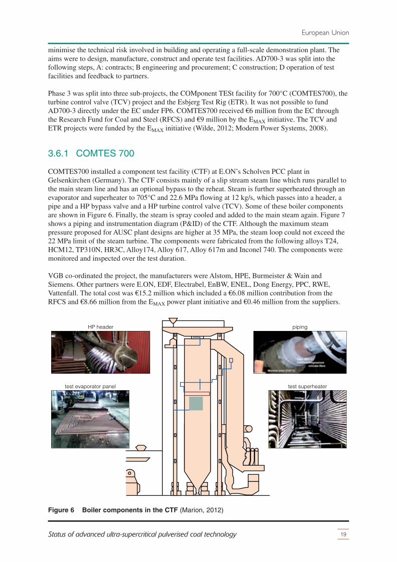
COMTES700 installed a component test facility (CTF) at E.ON’s Scholven PCC plant inGelsenkirchen (Germany). The CTF consists mainly of a slip stream steam line which runs parallel tothe main steam line and has an optional bypass to the reheat. Steam is further superheated through anevaporator and superheater to 705°C and 22.6 MPa flowing at 12 kg/s, which passes into a header, apipe and a HP bypass valve and a HP turbine control valve (TCV). Some of these boiler componentsare shown in Figure 6. Finally, the steam is spray cooled and added to the main steam again. Figure 7shows a piping and instrumentation diagram (P&ID) of the CTF. Although the maximum steampressure proposed for AUSC plant designs are higher at 35 MPa, the steam loop could not exceed the22 MPa limit of the steam turbine. The components were fabricated from the following alloys T24,HCM12, TP310N, HR3C, Alloy174, Alloy 617, Alloy 617m and Inconel 740. The components weremonitored and inspected over the test duration.
VGB co-ordinated the project, the manufacturers were Alstom, HPE, Burmeister & Wain andSiemens. Other partners were E.ON, EDF, Electrabel, EnBW, ENEL, Dong Energy, PPC, RWE,Vattenfall. The total cost was €15.2 million which included a €6.08 million contribution from theRFCS and�€8.66 million from the EMAX power plant initiative and €0.46 million from the suppliers.
19Status of advanced ultra-supercritical pulverised coal technology
European Union
test superheatertest evaporator panel
pipingHP header
Figure 6 Boiler components in the CTF (Marion, 2012)
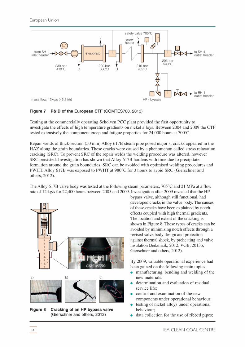
Testing at the commercially operating Scholven PCC plant provided the first opportunity toinvestigate the effects of high temperature gradients on nickel alloys. Between 2004 and 2009 the CTFtested extensively the component creep and fatigue properties for 24,000 hours at 700ºC.
Repair welds of thick-section (50 mm) Alloy 617B steam pipe posed major s; cracks appeared in theHAZ along the grain boundaries. These cracks were caused by a phenomenon called stress relaxationcracking (SRC). To prevent SRC of the repair welds the welding procedure was altered, howeverSRC persisted. Investigation has shown that Alloy 617B hardens with time due to precipitateformation around the grain boundaries. SRC can be avoided with optimised welding procedures andPWHT. Alloy 617B was exposed to PWHT at 980°C for 3 hours to avoid SRC (Gierschner andothers, 2012).
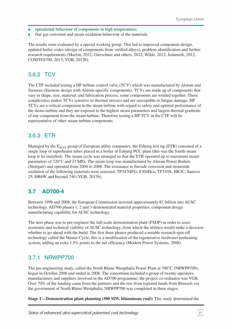
The Alloy 617B valve body was tested at the following steam parameters, 705°C and 21 MPa at a flowrate of 12 kg/s for 22,400 hours between 2005 and 2009. Investigation after 2009 revealed that the HP
bypass valve, although still functional, haddeveloped cracks in the valve body. The causesof these cracks have been explained by notcheffects coupled with high thermal gradients.The location and extent of the cracking isshown in Figure 8. These types of cracks can beavoided by minimising notch effects through arevised valve body design and protectionagainst thermal shock, by preheating and valveinsulation (Jedamzik, 2012; VGB, 2013b;Gierschner and others, 2012).
By 2009, valuable operational experience hadbeen gained on the following main topics:� manufacturing, bending and welding of the
new materials;� determination and evaluation of residual
service life;� control and examination of the new
components under operational behaviour;� testing of nickel alloys under operational
behaviour;� data collection for the use of ribbed pipes;
20 IEA CLEAN COAL CENTRE
European Union
from SH 1inlet header
to SH 4outlet header
to RH 1outlet header
mass flow: 12kg/s (43,2 t/h)
evaporator
D
V
D
Vsuperheater
220 bar600°C
210 bar705°C
205 bar540°C
HP - bypass
safety valve 705°C
230 bar410°C
Figure 7 P&ID of the European CTF (COMTES700, 2013)
a) b) c)
weld
COMTES700cb
a
perforateddisc
Figure 8 Cracking of an HP bypass valve(Gierschner and others, 2012)
� operational behaviour of components in high temperatures;� flue gas corrosion and steam oxidation behaviour of the materials.
The results were evaluated by a special working group. This led to improved component design,updated boiler codes (design of components from verified alloys), problem identification and furtherresearch requirements (Marion, 2012; Gierschner and others, 2012; Wilde, 2012; Jedamzik, 2012;COMTES700, 2013; VGB, 2012b).
3.6.2 TCV
The CTF included testing a HP turbine control valve (TCV) which was manufactured by Alstom andSiemens (Siemens design with Alstom-specific components). TCVs are made up of components thatvary in shape, size, material, and fabrication process, some components are welded together. Thesecomplexities makes TCVs sensitive to thermal stresses and are susceptible to fatigue damage. HPTCVs are a critical component in the steam turbine with regard to safety and optimal performance ofthe steam turbine and they are exposed to the highest steam parameters and largest thermal gradientsof any component from the steam turbine. Therefore testing a HP TCV in the CTF will berepresentative of other steam turbine components.
3.6.3 ETR
Managed by the EMAX group of European utility companies, the Esbjerg test rig (ETR) consisted of asingle loop of superheater tubes placed in a boiler of Esbjerg PCC plant (this was the fourth steamloop to be installed). The steam cycle was arranged so that the ETR operated up to maximum steamparameters of 720°C and 27 MPa. The steam loop was manufactured by Alstom Power Boilers(Stuttgart) and operated from 2004 to 2008. The resistance to fireside corrosion and steamsideoxidation of the following materials were assessed, TP347HFG, S304Hcu, TP310N, HR3C, Sanicro25, HR6W and Inconel 740 (VGB, 2013b).
3.7 AD700-4
Between 1998 and 2008, the European Commission invested approximately €1 billion into AUSCtechnology. AD700 phases 1, 2 and 3 demonstrated material properties, component designmanufacturing capability for AUSC technology.
The next phase was to pre-engineer the full-scale demonstration plant (FSDP) in order to asseseconomic and technical viability of AUSC technology, from which the utilities would make a decisionwhether to go ahead with the build. The first three phases produced a notable research spin-offtechnology called the Master Cycle; this is a modification of the regenerative feedwater preheatingsystem, adding an extra 1.5% points to the net efficiency (Modern Power Systems, 2008).
3.7.1 NRWPP700
The pre-engineering study, called the North Rhine-Westphalia Power Plant at 700°C (NRWPP700),began in October 2006 and ended in 2008. The consortium included a group of twenty operators,manufacturers and suppliers involved in the AD700 programme; the project co-ordinator was VGB.Over 70% of the funding came from the partners and the rest from regional funds from Brussels viathe government of North Rhine-Westphalia. NRWPP700 was completed in three stages.
Stage 1 – Demonstration plant planning (500 MW, bituminous coal): This study determined the
21Status of advanced ultra-supercritical pulverised coal technology
European Union
technical and economic feasibility of a demonstration unit fired by bituminous coal. On the boilerside, three tower boiler concepts from Alstom, HPE, and Burmeister and Wain Energy were assessed.It was decided to opt for a HP boiler with steam parameters of 705/720/36.5 reaching over electricalefficiency (net, LHV). The steam turbine examined generated a total of 550 MWe at the shaft or500 MWe net taking into account auxiliary load. A smaller unit size was chosen as it minimises risk toinvestors. In 2012, the capital cost for this demonstration unit fired by bituminous coal was €1.7billion (>3000 €/kW). The following additional research projects were carried out in the scope ofNRWPP700:� production of a casing fabricated from Alloy 617m for a HP bypass valve;� processing and relaxation of new nickel alloys under modified cyclic load;� investigation of development possibilities for high-temperature sensors; � components designed for high temperatures;� non-destructive investigations of different welds to produce steam turbine rotors fabricated from
nickel alloys;� manufacture of a HP pipe extruded Alloy 617 in the extrusion process;� qualification of Inconel 740 for the steam generator superheater;� qualification of Alloy 617m for thick-section superheater pipes;� increased thermodynamic investigations regarding the Master Cycle;� HP pipe extruded from Alloy 617 (separately funded).
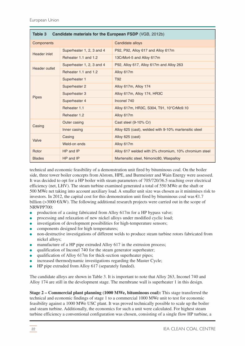
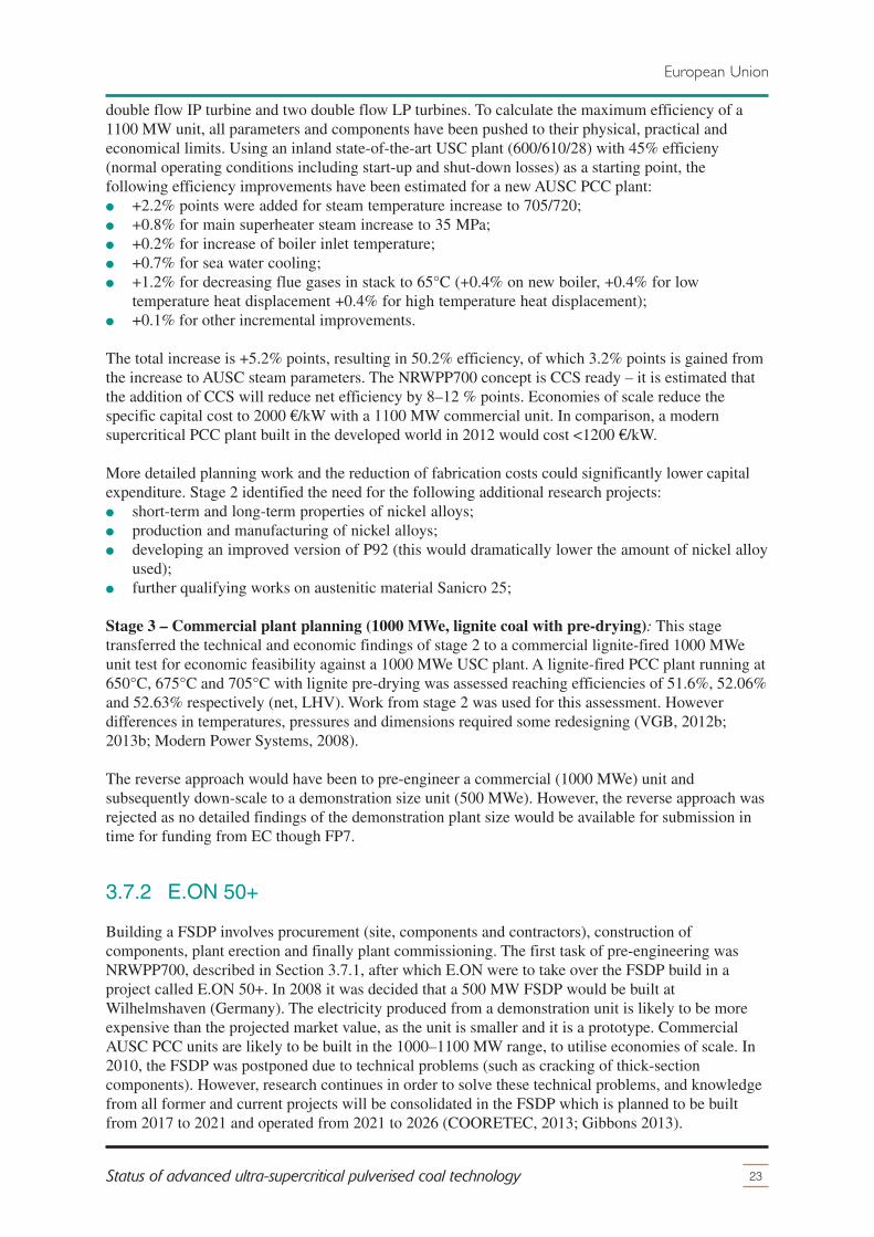
The candidate alloys are shown in Table 3. It is important to note that Alloy 263, Inconel 740 andAlloy 174 are still in the development stage. The membrane wall is superheater 1 in this design.
Stage 2 – Commercial plant planning (1000 MWe, bituminous coal): This stage transferred thetechnical and economic findings of stage 1 to a commercial 1000 MWe unit to test for economicfeasibility against a 1000 MWe USC plant. It was proved technically possible to scale up the boilerand steam turbine. Additionally, the economics for such a unit were calculated. For highest steamturbine efficiency a conventional configuration was chosen, consisting of a single flow HP turbine, a
22 IEA CLEAN COAL CENTRE
European Union
Table 3 Candidate materials for the European FSDP (VGB, 2012b)
Components Candidate alloys
Header inletSuperheater 1, 2, 3 and 4 P92, P92, Alloy 617 and Alloy 617m
Reheater 1.1 and 1.2 13CrMo4-5 and Alloy 617m
Header outletSuperheater 1, 2, 3 and 4 P92, Alloy 617, Alloy 617m and Alloy 263
Reheater 1.1 and 1.2 Alloy 617m
Pipes
Superheater 1 T92
Superheater 2 Alloy 617m, Alloy 174
Superheater 3 Alloy 617m, Alloy 174, HR3C
Superheater 4 Inconel 740
Reheater 1.1 Alloy 617m, HR3C, S304, T91, 10°CrMo9.10
Reheater 1.2 Alloy 617m
CasingOuter casing Cast steel (9-10% Cr)
Inner casing Alloy 625 (cast), welded with 9-10% martensitic steel
Valve Casing Alloy 625 (cast)
Weld-on ends Alloy 617m
Rotor HP and IP Alloy 617 welded with 2% chromium, 10% chromium steel
Blades HP and IP Martensitic steel, Nimonic80, Waspalloy
double flow IP turbine and two double flow LP turbines. To calculate the maximum efficiency of a1100 MW unit, all parameters and components have been pushed to their physical, practical andeconomical limits. Using an inland state-of-the-art USC plant (600/610/28) with 45% efficieny(normal operating conditions including start-up and shut-down losses) as a starting point, thefollowing efficiency improvements have been estimated for a new AUSC PCC plant: � +2.2% points were added for steam temperature increase to 705/720;� +0.8% for main superheater steam increase to 35 MPa;� +0.2% for increase of boiler inlet temperature;� +0.7% for sea water cooling;� +1.2% for decreasing flue gases in stack to 65°C (+0.4% on new boiler, +0.4% for low
temperature heat displacement +0.4% for high temperature heat displacement); � +0.1% for other incremental improvements.
The total increase is +5.2% points, resulting in 50.2% efficiency, of which 3.2% points is gained fromthe increase to AUSC steam parameters. The NRWPP700 concept is CCS ready – it is estimated thatthe addition of CCS will reduce net efficiency by 8–12 % points. Economies of scale reduce thespecific capital cost to 2000 €/kW with a 1100 MW commercial unit. In comparison, a modernsupercritical PCC plant built in the developed world in 2012 would cost <1200 €/kW.
More detailed planning work and the reduction of fabrication costs could significantly lower capitalexpenditure. Stage 2 identified the need for the following additional research projects:� short-term and long-term properties of nickel alloys;� production and manufacturing of nickel alloys;� developing an improved version of P92 (this would dramatically lower the amount of nickel alloy
used);� further qualifying works on austenitic material Sanicro 25;
Stage 3 – Commercial plant planning (1000 MWe, lignite coal with pre-drying): This stagetransferred the technical and economic findings of stage 2 to a commercial lignite-fired 1000 MWeunit test for economic feasibility against a 1000 MWe USC plant. A lignite-fired PCC plant running at650°C, 675°C and 705°C with lignite pre-drying was assessed reaching efficiencies of 51.6%, 52.06%and 52.63% respectively (net, LHV). Work from stage 2 was used for this assessment. Howeverdifferences in temperatures, pressures and dimensions required some redesigning (VGB, 2012b;2013b; Modern Power Systems, 2008).
The reverse approach would have been to pre-engineer a commercial (1000 MWe) unit andsubsequently down-scale to a demonstration size unit (500 MWe). However, the reverse approach wasrejected as no detailed findings of the demonstration plant size would be available for submission intime for funding from EC though FP7.
3.7.2 E.ON 50+
Building a FSDP involves procurement (site, components and contractors), construction ofcomponents, plant erection and finally plant commissioning. The first task of pre-engineering wasNRWPP700, described in Section 3.7.1, after which E.ON were to take over the FSDP build in aproject called E.ON 50+. In 2008 it was decided that a 500 MW FSDP would be built atWilhelmshaven (Germany). The electricity produced from a demonstration unit is likely to be moreexpensive than the projected market value, as the unit is smaller and it is a prototype. CommercialAUSC PCC units are likely to be built in the 1000–1100 MW range, to utilise economies of scale. In2010, the FSDP was postponed due to technical problems (such as cracking of thick-sectioncomponents). However, research continues in order to solve these technical problems, and knowledgefrom all former and current projects will be consolidated in the FSDP which is planned to be builtfrom 2017 to 2021 and operated from 2021 to 2026 (COORETEC, 2013; Gibbons 2013).
23Status of advanced ultra-supercritical pulverised coal technology
European Union
3.8 MARCKO DE2
The project ‘Material realisation low for a CO2 power plant’ or MARCKO DE2 started in April 1999and ended in March 2003. Managed by VGB, MARCKO DE2 helped qualify Alloy 617 for outletheaders and superheater tubes in AUSC boilers. Alstom Power Boilers in Stuttgart successfullyfabricated a steam header from Alloy 617m via GTAW and SAW procedures. It was funded by theGerman government through COORETEC and the Research Association of the Working Group of theIron and Metal Processing Industry (VGB, 2013b; Wilde, 2012).
GTAW narrow gap orbital welding has been shown to be the weld procedure of choice for martensiticsteels and nickel alloy tube to tube welds in PCC plant. The process is fully automated and producesefficient and reliable welds. Less filler material is required due to efficient use and the narrow gapsreduce the amount required. The automated process is quicker than the manual process. Automatedwelding is reproducible and ensures a constant level of quality. Grab and Stahl (2012) detail TIGnarrow gap welding and PWHT.
3.9 MARCKO 700
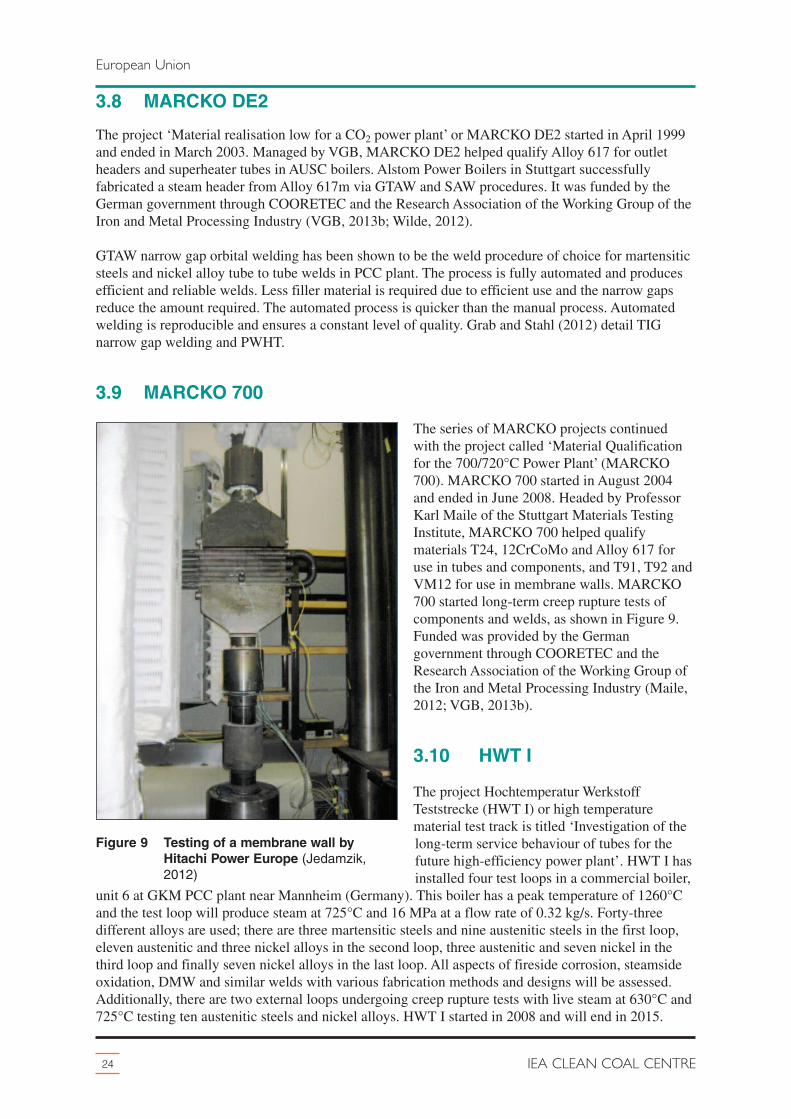
The series of MARCKO projects continuedwith the project called ‘Material Qualificationfor the 700/720°C Power Plant’ (MARCKO700). MARCKO 700 started in August 2004and ended in June 2008. Headed by ProfessorKarl Maile of the Stuttgart Materials TestingInstitute, MARCKO 700 helped qualifymaterials T24, 12CrCoMo and Alloy 617 foruse in tubes and components, and T91, T92 andVM12 for use in membrane walls. MARCKO700 started long-term creep rupture tests ofcomponents and welds, as shown in Figure 9.Funded was provided by the Germangovernment through COORETEC and theResearch Association of the Working Group ofthe Iron and Metal Processing Industry (Maile,2012; VGB, 2013b).
3.10 HWT I
The project Hochtemperatur WerkstoffTeststrecke (HWT I) or high temperaturematerial test track is titled ‘Investigation of thelong-term service behaviour of tubes for thefuture high-efficiency power plant’. HWT I hasinstalled four test loops in a commercial boiler,
unit 6 at GKM PCC plant near Mannheim (Germany). This boiler has a peak temperature of 1260°Cand the test loop will produce steam at 725°C and 16 MPa at a flow rate of 0.32 kg/s. Forty-threedifferent alloys are used; there are three martensitic steels and nine austenitic steels in the first loop,eleven austenitic and three nickel alloys in the second loop, three austenitic and seven nickel in thethird loop and finally seven nickel alloys in the last loop. All aspects of fireside corrosion, steamsideoxidation, DMW and similar welds with various fabrication methods and designs will be assessed.Additionally, there are two external loops undergoing creep rupture tests with live steam at 630°C and725°C testing ten austenitic steels and nickel alloys. HWT I started in 2008 and will end in 2015.
24 IEA CLEAN COAL CENTRE
European Union
Figure 9 Testing of a membrane wall byHitachi Power Europe (Jedamzik,2012)
Information gathered from the privately funded HWT I project will be used to qualify new superheatermaterials. Organisations involved include MPA University of Stuttgart, eight manufacturers, twoinspection authorities and four utility companies (Jiang, 2012; Maile and Metzger, 2012).
3.11 Post AD700
Collectively, the AD700 programme and the KOMET and MARCKO projects have successfullydemonstrated manufacturability of critical components from nickel alloys and assessed theirbehaviour at higher steam parameters with some excellent results. However, the cracking ofthick-section nickel alloys must be overcome, manufacturing costs reduced, fireside corrosion underbiomass and waste cofiring assessed, performance under static operation to severe cyclic operationguaranteed and 650°C steels developed to significantly improve the economics of AUSC technology.The issues are being tackled in AD700 which continues under the names of COMTES+ (ENCIO andHWTII), NextGenPower and MACPLUS.
3.12 COMTES+
In 2011, COMTES+ was set up by VGB to further qualify candidate AUSC materials in two calledENCIO and HWT II. COMTES+ will reuse components from COMTES700. Results fromCOMTES+ are expected by 2017 and should generate all the knowledge necessary to design, buildand operate a FSDP. Together these projects have a budget of approximately�€70 million, partlyfunded by the EC under FP7 (Gierschner and others, 2012; Maile and Metzger, 2012).
3.12.1 HWT II
Hochtemperatur Werkstoff Teststrecke (HWT) II primarily investigates the operation and failurebehaviour of thick-section components under base load and cyclic operation. The work will becompleted in a test loop at GKM PCC plant (Germany). HWT II started in January 2011 and isplanned to end by December 2014. There are 28 European partners and it is funded by industry(generating companies, equipment and material suppliers and inspection authorities involved) and theGerman government through COORETEC with a budget of €17.6 million.
Steam extracted from unit 6 at 530°C isheated to 725°C in superheaters fabricatedfrom materials P92, DMV310, A263, A740and A617B. The superheater pipes A740 andA617B are welded to a header fabricatedfrom A617B and A263 respectively. A bypassvalve is installed after the header to releasesteam out of the test loop in case of anemergency. The HP bypass supplied byHORA, which was originally manufacturedfor the E.ON 50+ demonstration plant, isshown in Figure 10. To avoid cracking of theHP bypass valve, the valve has beenredesigned and PWHT is used. The valve isof ‘flow to open design’, the valve body isforged from Alloy 617B and weighs2.6 tonnes and allows 2.75 kg/s of steamflow. The bypass piping includes a pressurereducing and de-superheating system
25Status of advanced ultra-supercritical pulverised coal technology
European Union
pos. 1
~800
625
~’90
0
pos. 2
Figure 10 HP bypass valve tested in HWT II(Gierschner and others, 2012)
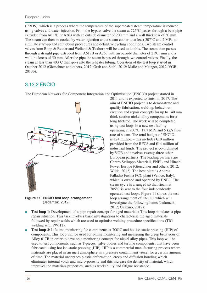
(PRDS), which is a process where the temperature of the superheated steam temperature is reduced,using valves and water injection. From the bypass valve the steam at 725°C passes through a bent pipeextruded from A617B or A263 with an outside diameter of 200 mm and a wall thickness of 50 mm.The steam can then be cooled by water injection and a steam cooler to at least 307°C and 2 MPa, tosimulate start-up and shut-down procedures and definitive cycling conditions. Two steam controlvalves from Bopp & Reuter and Welland & Tuxhorn will be used to do this. The steam then passesthrough a straight pipe extruded from A617B or A263 with an outside diameter of 219.1 mm and awall thickness of 50 mm. After the pipe the steam is passed through two control valves. Finally, thesteam at less than 400°C then goes into the reheater tubing. Operation of the test loop started inOctober 2012 (Gierschner and others, 2012; Grab and Stahl, 2012: Maile and Metzger, 2012; VGB,2013b).
3.12.2 ENCIO
The European Network for Component Integration and Optimisation (ENCIO) project started in2011 and is expected to finish in 2017. Theaim of ENCIO project is to demonstrate andqualify fabrication, welding, behaviour,erection and repair concepts for up to 140 mmthick-section nickel alloy components for along lifetime. The work will be completedusing test loops in a new test facilityoperating at 700°C, 17.7 MPa and 5 kg/s flowrate of steam. The total budget of ENCIOis�€24 million – this includes €10 millionprovided from the RFCS and €14 million ofindustrial funds. The project is co-ordinatedby VGB and involves twenty-three otherEuropean partners. The leading partners areCentro Sviluppo Materiali, ENEL and HitachiPower Europe (Gierschner and others, 2012;Wilde, 2012). The host plant is AndreaPalladio Fusina PCC plant (Venice, Italy),which is owned and operated by ENEL. Thesteam cycle is arranged so that steam at705°C is sent to the four independentlyoperated test loops. Figure 11 shows the testloop arrangement of ENCIO which willinvestigate the following items (Jedamzik,2012; Gazzino, 2012):
� Test loop 1: Development of a pipe repair concept for aged materials: This loop simulates a piperepair situation. This task involves basic investigations to characterise the aged materialsfollowed by repair welds which are used to optimise welding procedure specifications (TIGwelding with PWHT).
� Test loop 2: Lifetime monitoring for components at 700°C and hot iso-static pressing (HIP) ofcomponents. This loop will be used for online monitoring and measuring the creep behaviour ofAlloy 617B in order to develop a monitoring concept for nickel alloy pipes. This loop will beused to test components, such as T-pieces, valve bodies and turbine components, that have beenfabricated using hot iso-static pressing (HIP). HIP is a commercial manufacturing process wherematerials are placed in an inert atmosphere in a pressure containment vessel for a certain amountof time. The material undergoes plastic deformation, creep and diffusion bonding whicheliminates internal voids and micro-porosity and this increase the density of material, whichimproves the materials properties, such as workability and fatigue resistance.
26 IEA CLEAN COAL CENTRE
European Union
Figure 11 ENCIO test loop arrangement(Jedamzik, 2012)
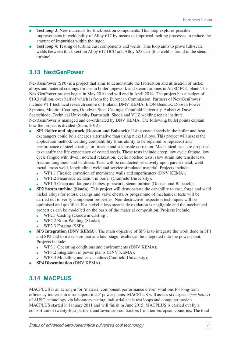
� Test loop 3: New materials for thick-section components: This loop explores possibleimprovements in weldability of Alloy 617 by means of improved melting processes to reduce theamount of impurities within the ingot.
� Test loop 4: Testing of turbine cast components and welds: This loop aims to prove full-scalewelds between thick-section Alloy 617 OCC and Alloy 625 cast (this weld is found in the steamturbine).
3.13 NextGenPower
NextGenPower (SP0) is a project that aims to demonstrate the fabrication and utilisation of nickelalloys and material coatings for use in boiler, pipework and steam turbines in AUSC PCC plant. TheNextGenPower project began in May 2010 and will end in April 2014. The project has a budget of€10.3 million, over half of which is from the European Commission. Partners of NextGenPowerinclude VTT technical research centre of Finland, DMV KEMA, E.ON Benelux, Doosan PowerSystems, Monitor Coatings, Goodwin Steel Castings, Cranfield University, Aubert & Duvel,Saarschiede, Technical University Darmstadt, Skoda and VUZ welding repair institute.NextGenPower is managed and co-ordinated by DNV KEMA. The following bullet points explainhow the project is divided (Stam, 2012).� SP1 Boiler and pipework (Doosan and Babcock): Using coated steels in the boiler and heat
exchangers could be a cheaper alternative than using nickel alloys. This project will assess theapplication method, welding compatibility (thus ability to be repaired or replaced) andperformance of steel coatings in fireside and steamside corrosion. Mechanical tests are proposedto quantify the life expectancy of coated steels. These tests include creep, low cycle fatigue, lowcycle fatigue with dwell, notched relaxation, cyclic notched tests, slow strain rate tensile tests,fracture toughness and hardness. Tests will be conducted selectively upon parent metal, weldmetal, cross weld, longitudinal weld and service simulated material. Projects include:� WP1.1 Fireside corrosion of membrane walls and superheaters (DNV KEMA);� WP1.2 Steamside oxidation in boiler (Cranfield University);� WP1.3 Creep and fatigue of tubes, pipework, steam turbine (Doosan and Babcock);
� SP2 Steam turbine (Skoda): This project will demonstrate the capability to cast, forge and weldnickel alloys for rotors, casings and valve chests. A programme of mechanical tests will becarried out to verify component properties. Non-destructive inspection techniques will beoptimised and qualified. For nickel alloys steamside oxidation is negligible and the mechanicalproperties can be modelled on the basis of the material composition. Projects include:� WP2.1 Casting (Goodwin Casting);� WP2.2 Rotor Welding (Skoda);� WP2.3 Forging (SSF);
� SP3 Integration (DNV KEMA): The main objective of SP3 is to integrate the work done in SP1and SP2 and to make sure that at a later stage results can be integrated into the power plant.Projects include:� WP3.1 Operating conditions and environments (DNV KEMA);� WP3.2 Integration in power plants (DNV KEMA);� WP3.3 Modelling and case studies (Cranfield University);
� SP4 Dissemination (DNV KEMA).
3.14 MACPLUS
MACPLUS is an acronym for ‘material component performance driven solutions for long-termefficiency increase in ultra-supercritical’ power plants. MACPLUS will assess six aspects (see below)of AUSC technology via laboratory testing, industrial-scale test loops and computer models.MACPLUS started in January 2011 and will finish in June 2015. MACPLUS is carried out by aconsortium of twenty-four partners and seven sub-contractors from ten European countries. The total
27Status of advanced ultra-supercritical pulverised coal technology
European Union

budget is €18.2 million, of which €10.7 million is provided from the EC under FP7. MACPLUS issplit into the following projects (Zanin, 2013; MACPLUS, 2013):� WP1 (Foster Wheeler Energia) will investigate new refractory materials.� WP2 (Technical University of Graz) will investigate new ferritic and martensitic steels (MARBN
and FB2 mod) for use in headers and pipework to avoid premature Type IV cracking of welds.� WP3 (Centro Sviluppo Materiali) aims to understand the operational behaviour of austenitic
steels and nickel alloys in superheaters using laboratory specimens and materials from previoustest loops, such as the AD700-3. Material modifications via fabrication and composition will beassessed along with long-term behaviour extrapolation via modelling. A superheater tube andwelded joints of thick-section pipes fabricated from modified nickel alloy will be fabricated andtested to demonstrate improved performance.
� WP4 (Doosan Power Systems) will assess fabrication and application processes of multi-layerand multi-material boiler tubes for application in aggressive fireside conditions.
� WP5 (Alstom) will assess high temperature components in a steam turbine using latestgeneration high alloy steels for use at 620–670°C and nickel alloys at 670–720°C. This will becompleted via metallurgical-thermo-mechanical modelling and manufacturing.
� WP6 (E.ON New Build & Technology) aims to develop advanced design and testing criteria forhigh temperature components development, integration and standardisation into AUSC PCCplant. This work will build on existing testing methods in order to identify future developmentneeds.
� WP7 (Centro Sviluppo Materiali) is simply the co-ordination and dissemination of projectsWP1–6.
3.15 IMPACT
Based in the UK, the ‘Innovative Materials Design and Monitoring of Power Plant to AccommodateCarbon Capture’ (IMPACT) project is a joint venture between E.ON New Build & Technology (plantuser), Doosan Power Systems (boiler and welding), Alstom (turbine and components), Goodwin SteelCastings (cast component supplier), National Physical Laboratory (monitoring technology) andLoughborough University (microstructural characterisation and modelling). The total budget is£1.8 million, partly government funded through the Technology Strategy Board, and runs from 2010to 2013. There are three objectives within the project:1 Develop of advanced welded MARBN steels for power plant;2 Improve the design for welded components to reduce premature cracking;3 Improve the strain and materials monitoring to allow high temperature operation.
The proportion of boron in steels has been previously altered with inconsistent results. Fujio Abe ofNational Institute for Materials Science (NIMS) of Japan found that alloying boron with nitrogen incertain amounts achieves high creep rupture resistance; MARBN steel (MARtensite plus boron plusnitrogen) was discovered. The IMPACT project has optimised the composition of MARBN steel andshort-term tests have shown that MARBN has 20–40% higher creep rupture resistance than P92 attemperatures up to 675°C. Heat treatment at 1200°C further increases the creep rupture resistance by10–15%. Potentially, MARBN has 55% higher creep rupture resistance than P92. However, MARBNsteel shows a substantial weld strength reduction and is susceptible to cracking in the HAZ. Theproportions of the alloying elements in MARBN need not be exact – a wide range is acceptable forsimilar properties. In May 2012, Goodwin Steel Castings (UK) produced an eight tonne melt ofMARBN, from which ingots and castings were fabricated and welded. These components are now inlong-term tests (Allen and others, 2013).
3.16 KMM-VIN WG2
The European Virtual Institute on Knowledge-based Multifunctional Materials (KMM-VIN) was
28 IEA CLEAN COAL CENTRE
European Union

established in 2007 and aims to foster the creation of a powerful platform for research anddevelopment and industrial application of advanced materials. In 2012, KMM-VIN integrated themembers and plans from the cancelled COST 556 EMEP project along with old KMM-VIN membersinterested in different materials for energy applications into its agenda to form Working Group 2:Materials for Energy (WG2). KMM-VIN WG2) is an unfunded collaboration seeking to promote andco-ordinate research into advanced steels. Individual project are funded by private sources, nationalgovernments or the EC.
KMM-VIN WG2 is made up of 72 research establishments and 25 companies across Europe. TheAUSC technology projects facilitated by KMM-VIN WG2 co-ordination effort are detailedsubsequently (KMM-VIN, 2013).
3.16.1 EBW
Technical University of Graz and Voest-alpine Giesserei Traisen are researching DMW using electronbeam welding (EBW). EBW has no filler material, shorter welding time, less machining time for jointpreparation and smaller fusion zone. Nickel alloy 625 has been welded to 9% chromium steel CB2using EBW, no defects have been found and testing has shown good mechanical properties. Creeprupture tests are planned.
3.16.2 MARBN
Working with the IMPACT project, Technical University of Graz and Technical University ofChemnitz are characterising MARBN steel and the corresponding welding process.
3.16.3 Z Ultra
Z Ultra is short for ‘Z-phase strengthened steels for ultra-supercritical power plants’. Z Ultra started inFebruary 2013 and is partially funded by the EC under FP7. Z Ultra was developed independently ofKMM-VIN WG2. Z Ultra aims to improve the creep rupture strength of martensitic 12% chromiumsteels by increasing the amount of Z phase precipitates for operation with 650ºC steam. Numeroussteels, filler materials and welding processes are being assessed. Atomic scale microstructuralinvestigations are employed to save time. Microstructure modelling will also be established to hastenresearch, improve understanding, and provide design tools and lifetime estimation methods for theoperation of future power plants. The project co-ordinator is Fraunhofer IWM (Germany) and involvesten partners, some non-EU.
3.17 Rafako
Rafako (Poland) have undertaken a research project that aims to calculate the highest possible steamparameters using commercially available materials. These materials must meet the applicableEuropean standards and therefore represent a boiler that is commercially available. Firstly, the criticalboiler components were identified. Secondly, the global steel market was analysed. Thirdly, the mostsuitable materials were selected for critical components. Finally, the highest possible steamparameters for the selected materials were calculated, regarding strength only, using the TRD-ENprogramme to achieve a 200,000 hour operating time. Corrosion and oxidation have been assumed notto become a problem within the 200,000 hour operating time. Some elements were recalculated by theANSYS programme (finite elements method). The result is a boiler with steam parameters of653/672/30, achieving 48% efficiency (LHV, net, coal heating value of 25MJ/kg, 94% boilerefficiency, 4.5 kPa condenser pressure). The materials needed would include only 15% austenitic steel
29Status of advanced ultra-supercritical pulverised coal technology
European Union

and 5% nickel based alloy. A problem with this study however is that there is no commerciallyavailable steam turbine that can operate at these steam parameters (Cieszynski and Kaczorowski,2012).
3.18 Summary
High temperature material research programmes in Europe are steered largely by a consortium oflarge utilities under the name of the EMAX initiative. Funding for the majority of projects has comefrom the European Commission and German government (mostly through COORETEC) and to alesser extent the UK and Swiss governments; some projects have been financed purely by utilities.
Starting in 1998, the AD700 programme in Europe involve up to forty partners and aimed to developAUSC technology at 700°C and 37.5MPa. The entire project, including operation and evaluation of afull-scale demonstration plant (FSDP) was initially planned for completion in 2018. A pre-engineeringstudy of a full-scale demonstration project (FSDP) called the North Rhine-Westphalia Power Plant at700°C project was completed in 2009 and concluded that the FSDP would have a net efficiency of50.2% (LHV, hard coal). After four years of operating and subsequent evaluation of components fromcomponent test facilities (CTF) in AD700 phase 3 (COMTES700, TCV and ETR projects), crackswere found in thick-section components which ultimately postponed construction of the FSDP. TheAD700 programme continues until 2017 under the names of COMTES+, with the HWT II project inGermany and ENCIO project in Italy, NexGenPower and MACPLUS which aim to solve problemswith, improve and develop new materials, assess the effect of biomass and waste cofiring on materialsand reduce manufacturing costs.
During the AD700 programme, MARCKO DE2 helped qualify Alloy 617 for outlet headers andsuperheater tubes. MARCKO 700 helped qualify materials T24, 12CrCoMo and Alloy 617 for use intubes and components, and T91, T92 and VM12 for use in membrane walls. HWT I is in the processof qualifying numerous materials and welds for superheaters. The government funded steel researchprogramme COST was cancelled in 2011 but continued as KMM-VIN WG2, an unfundedcollaboration seeking to promote and co-ordinate research into advanced steels. The importance of650°C steels if further demonstrated by the CRESTA and IMPACT projects.
There are plans in Europe to build a FSDP (500 MW at 705/720/35) in 2017-21, with operation andfeedback in 2021-26. The numerous high temperature material research programmes and projects inEurope have produced notable research spin-offs for use in USC plant, such as improved steels,boilers and steam cycle designs.
30 IEA CLEAN COAL CENTRE
European Union

4 USA
31Status of advanced ultra-supercritical pulverised coal technology
The USA has one of the largest coal reserves in the world and has helped pioneer the use of new hightemperature materials in PCC plant. The fleet of PCC plant is approaching the end of its design lifeand new power plant need to be built. However, the recent advent of shale gas extraction hasdramatically lowered gas prices.
The programme on ‘Advanced Ultra-supercritical Power Plant Materials’ in the USA started in 2001.The research programme is financially supported by the US Department of Energy and Ohio Office ofCoal Development, and is split into two consortia, the major US boiler manufacturers (Alstom,Babcock & Wilcox, Foster Wheeler, Riley Power, GE Energy) and US steam turbine manufacturers(Alstom, GE energy, Siemens). The national laboratories, Oak Ridge National Laboratory and theNational Energy Technology Laboratory support both consortia. The research programme is managedby the Energy Industries of Ohio with the Electrical Power Research Institute serving as theprogramme technical lead.
The boiler side of the programme is split into two phases. Phase one has been split into eight tasks. Phasetwo extends and enhances on tasks in phase one. The boiler side of the programme will assess alloys in airfired and pure oxygen fired boilers (also known as oxyfuel combustion/oxy-combustion/oxyfuel), cyclicoperation, material coatings and the effects on fireside corrosion of firing high sulphur coalsindigenous to the USA. The steam turbine side of the programme is split into two phases, phase onehas selected candidate materials and phase two will test these materials in six tasks (Romanosky,2012; Marion, 2012; Shingledecker, 2012). Figure 12 is a Gantt chart which shows the US materialresearch programme (Romanosky, 2012; Phillips, 2011).
The National Energy Technology Laboratory are aiming for 760ºC (1400ºF) maximum temperatureand 35 MPa (5000 psi) maximum pressure, with efficiencies of 45–47% (net, HHV) and acorresponding drop in carbon dioxide emissions of 15–22% (Romanosky, 2012). Alstom haveestimated an increase of efficiency of 7 percentage points when going from USC to AUSC steamparameters (Marion, 2012). Alstom argue that 760ºC maximum temperatures should be reached asopposed to 700ºC for three reasons. Firstly, nickel alloys can reach this temperature. Secondly, thecost of precipitation strengthened nickel alloy needed for 760ºC is the same as solution strengthenedalloy for 700ºC. Finally, conventional PCC plant configuration can exploit temperatures of 760ºC(Marion, 2012).
4.1 Boiler
Figure 13 shows the tasks of the boiler project. The following sections describe each of the tasks andassess their current status.
4.1.1 Task 1: Conceptual design
Alstom have completed designs for a 550 MW and 1100 MW tower AUSC boiler and steam turbineset based on proven conventional configuration and experience. In late 2012, Alstom were designing a1000 MW two-pass AUSC boiler and were assessing the possibility of placing the HP turbine higherto shorten the superheater steam pipe with an 1100 MW boiler; the intermediate pressure (IP) and HPturbines would remain at ground level (Marion, 2012).
Babcock & Wilcox have a modified AUSC tower boiler design which is based on proven USC boilers.The modified tower design combines features of both tower boiler and two-pass designs; advantages

include minimised steamside oxidation andfireside corrosion, improved reheat control,lower overall height, and shorter pipework.Babcock & Wilcox state that they have a boilerready for main and reheat temperatures of700ºC and 730ºC respectively. Babcock &Wilcox are working with steam turbinemanufacturer Toshiba on alternative steamcycles to minimise piping length, for air firedand oxyfuel boilers with and without theaddition of CCS. Factors under considerationinclude single or double reheat, boilercapacity, steam turbine configuration, baseload and cyclic operation (starting conditions,turndown cycling, feedwater pump drive,sliding pressure, pure or throttle reserve,pressure ‘shelf’ at minimum load, rate of load
change) and the application of carbon capture (condensate heat exchangers for oxy-combustion heatrecovery and turbine steam extraction for post-combustion solvent regeneration). Babcock & Wilcoxare confident they will be able to manufacture a boiler capable of handling steam at 760ºC (McCauley,2012). When all the necessary information has been collected through tasks two to seven (detailed inFigure 13), including material costs, task one will be revisited in order to optimise the boiler design.
4.1.2 Task 1: Economic analysis
For more attractive economics, the material research programme in the USA uses higher strengthmaterials to achieve temperatures higher than 700ºC. An example of this concept can be demonstratedwith a comparison between pipework manufactured of materials Alloy 617 and Inconel 740H. Asingle reheat 750 MW boiler running at the following steam parameters 704/704°C and 732/760°Cwas used as a reference. The capital cost of the Inconel 740H pipework was estimated to be55–110 $/kg, Alloy 617 is considered to have an equivalent cost. The delivered cost for Inconel 740His 55 $/kg and the delivered cost for alloy 617 is 110 $/kg. Welding Inconel 740H is estimated to beless than half the cost of welding Alloy 617. The combined effect of these results demonstrates thatthe utilisation of 740H in place Alloy 617 in AUSC pipework will result in a significant cost savingswith regard to both capital and maintenance (Shingledecker, 2012).
Using historic prices for nickel, all studies show that the cost of electricity (COE) from AUSCtechnology is more expensive by 1.5–13% than USC technology, unless there is a carbon tax. If CCSwere deployed, the cost of electricity from AUSC technology would be cheaper than USC, for both airand oxygen fired combustion. Figure 14 shows an economic study completed by Alstom and Electric
32 IEA CLEAN COAL CENTRE
USA
Year20
08
materials R&D programme (tasks 1-8)
component test facility: design
component test facility: build
component test facility: operate
demonstration plant: design and permit
demonstration plant: build
demonstration plant: operation
2026
2001
2002
2003
2004
2005
2006
2007
2014
2009
2010
2011
2012
2013
2016
2015
2019
2017
2018
2020
2021
2024
2022
2023
2025
Figure 12 Gantt chart of the US research programme (Phillips, 2011)
1: conceptual design
2: material properties
3: steamside oxidation
4: fireside corrosion
5: welding
6: fabricability
7: coatings
8: design data and rules(including code interface)
Figure 13 Boiler tasks (Romanosky, 2012)

Power Research Institute. The x-axis shows the price of a carbon dioxide tax ($/t) and the y-axisshows percentage increase in COE as temperatures rise from 600ºC to 700ºC. Any point below thecolured area shows favourable economics, any point above the coloured area shows unfavourableeconomics. The coloured area takes into account the estimated capital cost of AUSC technology, anypoint in this region could be economically favourable or unfavourable (Marion, 2012).
4.1.3 Task 2: Mechanical properties
Mechanical testing is extensive and is split among the US boiler manufacturers and nationallaboratories. All data from mechanical testing are accumulated in a long-term material propertydatabase. Babcock & Wilcox are using finite element software (3D-FEA) to analyse stresses ofthick-section components (McCauley, 2012). Mechanical testing has found that Inconel 740H has ahigher allowable stress than other code-approved nickel alloys, such as Alloy 617 and Alloy 230.Therefore Inconel 740H requires thinner walls for a given stress than weaker alloys, which reducesthe quantity of material usage, the amount of welding required and puts less load on the structuralsupports, thus reducing time, cost and risk. Additionally, thinner pipes are less susceptible to crackingwith cyclic operation and Inconel 740H has a large forging window (its low flow stress allows forlong extrusions of pipes/tubes with a range of widths). Candidate materials have been selectedthrough basic mechanical tests, including creep rupture testing to 10,000 hours. Full-scale pressurisedcreep tests on candidate alloys are now being performed on heat treated cold-bent tubes. This will helpdetermine whether cold strain affects creep rupture strength. This data will be used as the basis to setrational cold-work limits for the guidelines in the ASME BPVC (Viswanathan, 2008a).
4.1.4 Task 3: Steamside oxidation
Initially materials, coated and non-coated, were screened by laboratory tests. Long-term testing isunder way in order to improve the understanding of long-term oxidation kinetics and exfoliation. In2012, Babcock & Wilcox were performing steamside oxidation tests of pieces, including coated testpieces, at 620°C, 650ºC, 750ºC and 800ºC to 10,000 hours. Results to date have concluded thefollowing (McCauley, 2012):� austenitic steels show good resistance to oxidation and exfoliation up to 700ºC;
33Status of advanced ultra-supercritical pulverised coal technology
USA
favourable
10
8
6
4
2
-6
70
CO2 allowance price, $/tCO2
% C
OE
incr
ease
from
600
°C to
700
°C
12
14
6050403020100 100
0
-2
-4
9080
unfavourable
Alstom study-coal price A
EPRI study-coal price A
Alstom study-coal price B
EPRI study-coal price B
Figure 14 Economics of AUSC technology (Marion, 2012)
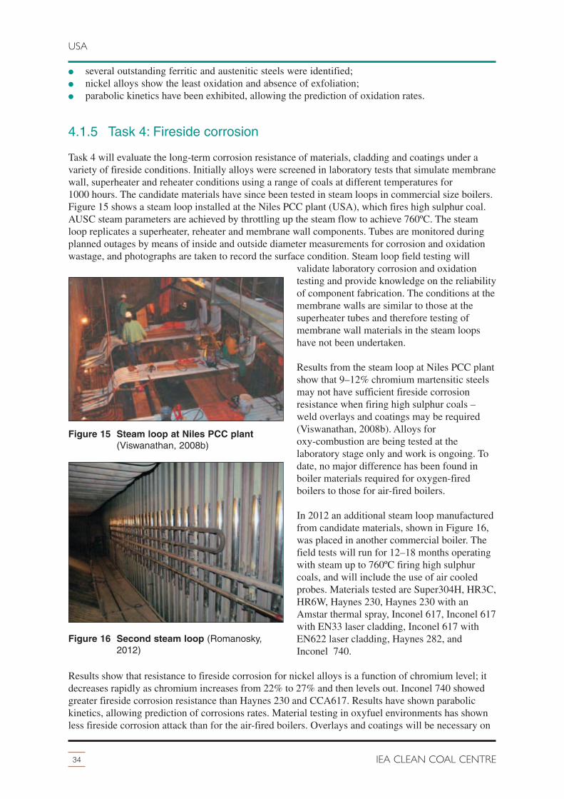
� several outstanding ferritic and austenitic steels were identified;� nickel alloys show the least oxidation and absence of exfoliation;� parabolic kinetics have been exhibited, allowing the prediction of oxidation rates.
4.1.5 Task 4: Fireside corrosion
Task 4 will evaluate the long-term corrosion resistance of materials, cladding and coatings under avariety of fireside conditions. Initially alloys were screened in laboratory tests that simulate membranewall, superheater and reheater conditions using a range of coals at different temperatures for1000 hours. The candidate materials have since been tested in steam loops in commercial size boilers.Figure 15 shows a steam loop installed at the Niles PCC plant (USA), which fires high sulphur coal.AUSC steam parameters are achieved by throttling up the steam flow to achieve 760ºC. The steamloop replicates a superheater, reheater and membrane wall components. Tubes are monitored duringplanned outages by means of inside and outside diameter measurements for corrosion and oxidationwastage, and photographs are taken to record the surface condition. Steam loop field testing will
validate laboratory corrosion and oxidationtesting and provide knowledge on the reliabilityof component fabrication. The conditions at themembrane walls are similar to those at thesuperheater tubes and therefore testing ofmembrane wall materials in the steam loopshave not been undertaken.
Results from the steam loop at Niles PCC plantshow that 9–12% chromium martensitic steelsmay not have sufficient fireside corrosionresistance when firing high sulphur coals –weld overlays and coatings may be required(Viswanathan, 2008b). Alloys foroxy-combustion are being tested at thelaboratory stage only and work is ongoing. Todate, no major difference has been found inboiler materials required for oxygen-firedboilers to those for air-fired boilers.
In 2012 an additional steam loop manufacturedfrom candidate materials, shown in Figure 16,was placed in another commercial boiler. Thefield tests will run for 12–18 months operatingwith steam up to 760ºC firing high sulphurcoals, and will include the use of air cooledprobes. Materials tested are Super304H, HR3C,HR6W, Haynes 230, Haynes 230 with anAmstar thermal spray, Inconel 617, Inconel 617with EN33 laser cladding, Inconel 617 withEN622 laser cladding, Haynes 282, andInconel 740.
Results show that resistance to fireside corrosion for nickel alloys is a function of chromium level; itdecreases rapidly as chromium increases from 22% to 27% and then levels out. Inconel 740 showedgreater fireside corrosion resistance than Haynes 230 and CCA617. Results have shown parabolickinetics, allowing prediction of corrosions rates. Material testing in oxyfuel environments has shownless fireside corrosion attack than for the air-fired boilers. Overlays and coatings will be necessary on
34 IEA CLEAN COAL CENTRE
USA
Figure 15 Steam loop at Niles PCC plant(Viswanathan, 2008b)
Figure 16 Second steam loop (Romanosky,2012)
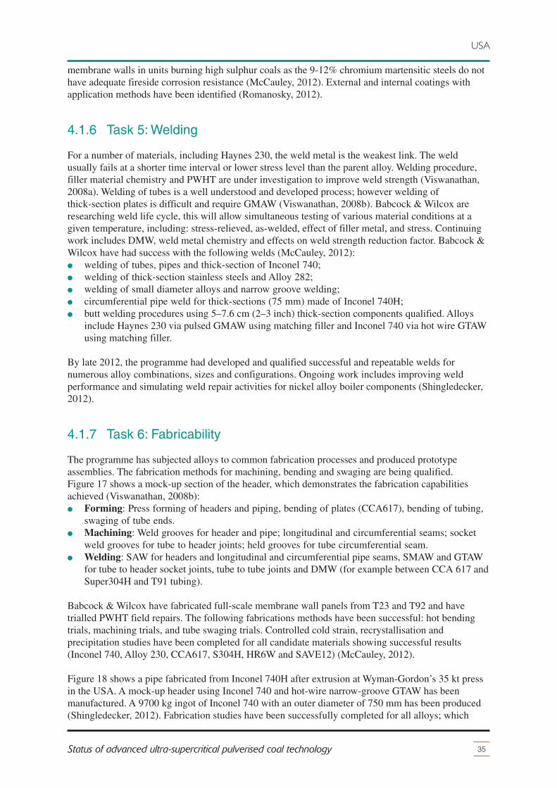
membrane walls in units burning high sulphur coals as the 9-12% chromium martensitic steels do nothave adequate fireside corrosion resistance (McCauley, 2012). External and internal coatings withapplication methods have been identified (Romanosky, 2012).
4.1.6 Task 5: Welding
For a number of materials, including Haynes 230, the weld metal is the weakest link. The weldusually fails at a shorter time interval or lower stress level than the parent alloy. Welding procedure,filler material chemistry and PWHT are under investigation to improve weld strength (Viswanathan,2008a). Welding of tubes is a well understood and developed process; however welding ofthick-section plates is difficult and require GMAW (Viswanathan, 2008b). Babcock & Wilcox areresearching weld life cycle, this will allow simultaneous testing of various material conditions at agiven temperature, including: stress-relieved, as-welded, effect of filler metal, and stress. Continuingwork includes DMW, weld metal chemistry and effects on weld strength reduction factor. Babcock &Wilcox have had success with the following welds (McCauley, 2012):� welding of tubes, pipes and thick-section of Inconel 740;� welding of thick-section stainless steels and Alloy 282;� welding of small diameter alloys and narrow groove welding;� circumferential pipe weld for thick-sections (75 mm) made of Inconel 740H;� butt welding procedures using 5–7.6 cm (2–3 inch) thick-section components qualified. Alloys
include Haynes 230 via pulsed GMAW using matching filler and Inconel 740 via hot wire GTAWusing matching filler.
By late 2012, the programme had developed and qualified successful and repeatable welds fornumerous alloy combinations, sizes and configurations. Ongoing work includes improving weldperformance and simulating weld repair activities for nickel alloy boiler components (Shingledecker,2012).
4.1.7 Task 6: Fabricability
The programme has subjected alloys to common fabrication processes and produced prototypeassemblies. The fabrication methods for machining, bending and swaging are being qualified.Figure 17 shows a mock-up section of the header, which demonstrates the fabrication capabilitiesachieved (Viswanathan, 2008b):� Forming: Press forming of headers and piping, bending of plates (CCA617), bending of tubing,
swaging of tube ends.� Machining: Weld grooves for header and pipe; longitudinal and circumferential seams; socket
weld grooves for tube to header joints; held grooves for tube circumferential seam.� Welding: SAW for headers and longitudinal and circumferential pipe seams, SMAW and GTAW
for tube to header socket joints, tube to tube joints and DMW (for example between CCA 617 andSuper304H and T91 tubing).
Babcock & Wilcox have fabricated full-scale membrane wall panels from T23 and T92 and havetrialled PWHT field repairs. The following fabrications methods have been successful: hot bendingtrials, machining trials, and tube swaging trials. Controlled cold strain, recrystallisation andprecipitation studies have been completed for all candidate materials showing successful results(Inconel 740, Alloy 230, CCA617, S304H, HR6W and SAVE12) (McCauley, 2012).
Figure 18 shows a pipe fabricated from Inconel 740H after extrusion at Wyman-Gordon’s 35 kt pressin the USA. A mock-up header using Inconel 740 and hot-wire narrow-groove GTAW has beenmanufactured. A 9700 kg ingot of Inconel 740 with an outer diameter of 750 mm has been produced(Shingledecker, 2012). Fabrication studies have been successfully completed for all alloys; which
35Status of advanced ultra-supercritical pulverised coal technology
USA

includes the production of large boilercomponents (Shingledecker, 2012).
4.1.8 Task 8: Material standards
Inconel 740/740H was found to have sufficienthigh creep rupture strength of over 100 MPa for100,000 hours, fireside corrosion resistance of2 mm per 200,000 hours and weldability foroperation at 760°C. Based on the consortium’sdata, Inconel 740/740H and related header tosuperheater welds were approved by ASME inSeptember 2011 (Code Case 2702 for UNSN07740) (Shingledecker, 2012).
4.2 Steam turbine
The steam turbine part of the programme issplit into phases. Phase 1 screens alloys forfurther investigation in phase 2. Phase 2 is splitinto the following six tasks (Romanosky, 2012):� rotor/disc testing (large-scale forgings);� blade/air foil alloy testing;� valve internals alloy testing;� rotor alloy welding and characterisation;� cast casing alloy testing;� casing welding and repair.
Phase 1 found the following materials for steamturbine application, Haynes 282, Alloy 617,Alloy 263, Sanicro 25, Inconel 740 and Alloy625. Haynes 282 appears the most attractive forthe steam turbine rotors (Shingledecker, 2012).Phase 2 is under way.
Alstom have used their conventional andproven steam turbine design for AUSC steamparameters, with the application of nickel alloysand austenitic steels in the highest temperatureregions. Nickel alloy and ferritic steel are usedto forge rotors and casings. There is no changein standard procedures and design rules for the
safe introduction of a higher temperature steam turbine. However, new fabrication techniques arerequired for new materials. One challenge is the DMW when welding ferritic steel to nickel alloy forthe HP and IP steam turbines. To simulate the rotor DMW, Alstom have welded a full-scale test blockof Alloy 617 to ferritic steel and Alloy 625 to ferritic steel. However, the stability in operation of theDMW remains unproven. Operational flexibility is ensured by using a shrink-ring inner casing designthat has minimal thermal stresses during cyclic operation. This ensures capability for rapid start-upand shut-down load changes (Shingledecker, 2012).
Research on castings identified key materials for large turbine and valve components, includingHaynes 282. The first ingot of triple melted Haynes 282 was produced in 2012 and is now being
36 IEA CLEAN COAL CENTRE
USA
Figure 17 Mock-up header manufactured byAlstom USA (Viswanathan, 2008b)
Figure 18 Inconel 740H pipe after extrusion(Shingledecker, 2012)
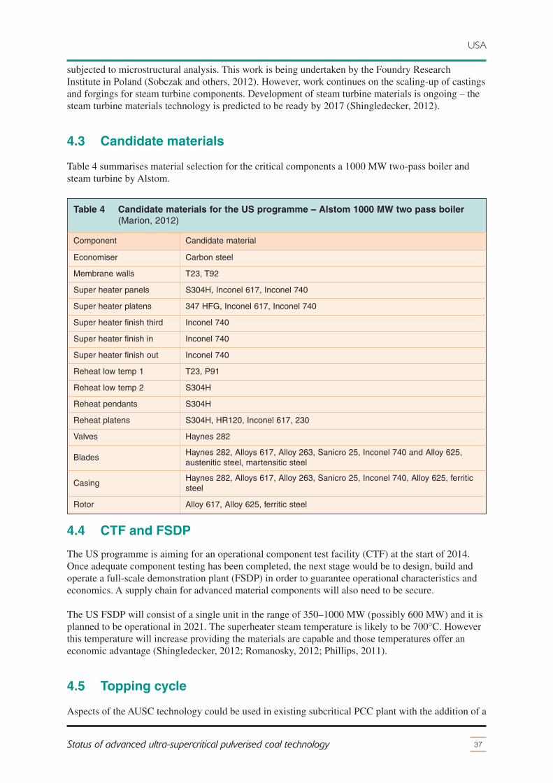
subjected to microstructural analysis. This work is being undertaken by the Foundry ResearchInstitute in Poland (Sobczak and others, 2012). However, work continues on the scaling-up of castingsand forgings for steam turbine components. Development of steam turbine materials is ongoing – thesteam turbine materials technology is predicted to be ready by 2017 (Shingledecker, 2012).
4.3 Candidate materials
Table 4 summarises material selection for the critical components a 1000 MW two-pass boiler andsteam turbine by Alstom.
37Status of advanced ultra-supercritical pulverised coal technology
USA
Table 4 Candidate materials for the US programme – Alstom 1000 MW two pass boiler(Marion, 2012)
Component Candidate material
Economiser Carbon steel
Membrane walls T23, T92
Super heater panels S304H, Inconel 617, Inconel 740
Super heater platens 347 HFG, Inconel 617, Inconel 740
Super heater finish third Inconel 740
Super heater finish in Inconel 740
Super heater finish out Inconel 740
Reheat low temp 1 T23, P91
Reheat low temp 2 S304H
Reheat pendants S304H
Reheat platens S304H, HR120, Inconel 617, 230
Valves Haynes 282
BladesHaynes 282, Alloys 617, Alloy 263, Sanicro 25, Inconel 740 and Alloy 625,austenitic steel, martensitic steel
CasingHaynes 282, Alloys 617, Alloy 263, Sanicro 25, Inconel 740, Alloy 625, ferriticsteel
Rotor Alloy 617, Alloy 625, ferritic steel
4.4 CTF and FSDP
The US programme is aiming for an operational component test facility (CTF) at the start of 2014.Once adequate component testing has been completed, the next stage would be to design, build andoperate a full-scale demonstration plant (FSDP) in order to guarantee operational characteristics andeconomics. A supply chain for advanced material components will also need to be secure.
The US FSDP will consist of a single unit in the range of 350–1000 MW (possibly 600 MW) and it isplanned to be operational in 2021. The superheater steam temperature is likely to be 700°C. Howeverthis temperature will increase providing the materials are capable and those temperatures offer aneconomic advantage (Shingledecker, 2012; Romanosky, 2012; Phillips, 2011).
4.5 Topping cycle
Aspects of the AUSC technology could be used in existing subcritical PCC plant with the addition of a
Topping Cycle. Steam at 680°C would pass from the superheaters to the Topping turbine-generatorbefore passing through the existing three stage steam turbine; which can raise the efficiency by3–3½ percentage points (Phillips, 2012).
4.6 Summary
The US research programme started in 2001. There are ten participants, consisting of the major USboiler and steam turbine manufacturers and national laboratories. The American programme is aimingfor higher steam temperatures than other programmes, with up to 730°C superheat and 760°C reheatsteam temperatures under air-fired and oxyfuel conditions. Significant progress has been made on theboiler side. Tests in the laboratory and in larger -scale boiler test loops have been completed. Weldingprocesses and fabrication techniques have been established for some materials. A design for a boilerwith a list of candidate materials for critical components has been completed. This progress has led tothe code approval of Inconel 740/740H for use in boilers by the American Society of MechanicalEngineers. Research on the steam turbine is progressing, Alstom plan to use their proven steamturbine design with nickel alloys and use welded rotors to reduce costs.
A large-scale component test facility (CTF) is planned to be operational from 2014 to 2017. There areplans in the USA to build a FSDP (350–1000 MW at 700/730/35) in 2017–21 with operation andfeedback in 2021-26. An interesting research spin-off is where an AUSC steam turbine is added to aUSC pulverised coal combustion (PCC) plant.
38 IEA CLEAN COAL CENTRE
USA
5 Japan
39Status of advanced ultra-supercritical pulverised coal technology
Japan imports fossil fuels due to scarce indigenous reserves – this makes energy in Japan expensive.Japan has a high population density, creating relatively high amounts of pollutant emissions per unitarea, adversely affecting the environment and public health. To counter these two factors, Japan usesfossil fuels efficiently and has substantial pollutant mitigation technologies in place. It is no surprise,therefore, that Japan operates one of the most efficient and cleanest fleet of PCC plant in the world.
Research and development on super alloys for use in AUSC technology started in Japan in 2000. Thework was headed by the Electrical Power Development Centre (EPDC) and strongly supportedthrough the Ministry of Trade and Industry (Sven, 2001). Prior to 2008, the National Institute forMaterials Science (NIMS) completed a feasibility study of AUSC technology with superheat steamtemperature of 700°C. The study showed that efficiencies can reach 46–48% (net, bituminous coal,HHV) which is economically and environmentally favourable, and that technical viability lookspromising. The study also found that it is technically feasible to retrofit AUSC technology to olderPCC plant in Japan.
In March 2008 AUSC technology was selected by the Japanese government’s ‘Cool Earth-InnovativeTechnology Programme’ as one of the technologies to reduce carbon dioxide emissions (Fukuda,2012a). The Japanese programme has four committees; the lead AUSC technology developmentcommittee, and three sub-committees, for the boiler, valves and steam turbine. The twelve companiesand institutions participating in the programme and organised into their working topics are(Fukuda, 2012a):� boiler: ABB Bailey Japan, Central Research Institute of Electric Power Industry,
Ishikawajima-Harima Heavy Industries, Mitsubishi Heavy Industries, NIMS, and Sumitomo;� valves: Fuji Electric (lead), Hitachi, Mitsubishi Heavy Industries, Toshiba, ABB Bailey Japan
(bypass valves), Okano Valve and Toa Valve (safety and control valves);� steam turbine: Babcock-Hitachi, Mitsubishi Heavy Industries and Toshiba.
Observers include numerous Japanese universities, the Japan Steel Works and the Ministry ofEconomy, Trade and Industry. Figure 19 shows a Gantt chart of the Japanese AUSC researchprogramme, which started in August 2008 It has detailed plans for nine years until 2017 and roughplans until 2026. The programme aims to have an operational demonstration plant by 2021 (Saito,2012; Fukuda, 2012a,b; Imano, 2012).
5.1 Chemical and mechanical tests
The first part of the Japanese research programme will identify new materials through mechanical andchemical tests. Mechanical tests include fatigue, tensile, long-term creep rupture, bending, weldingand non-destructive testing. Chemical tests include steamside oxidation and fireside corrosion, whichare explained below.
5.1.1 Fireside corrosion
A material corrosion database is being compiled from materials testing in laboratories, steam loopsand the investigation of operating power plants. The amount of corrosion can be extrapolated givendata about the corrosion rate of the material, flue gas composition, metal and gas temperatures and ashdeposition via computational fluid dynamic (CFD) analysis. Material protection methods such asweld-overlays and chromising will be tested. Laboratory testing has shown that nickel alloys andnickel and iron based alloys have similar fireside corrosion resistance to conventional austenitic steels.

The testing of fireside corrosion on new materials and protection methods under biomass cofiring willbe undertaken (Fukuda, 2012b).
5.1.2 Steamside oxidation
A materials oxidation database is being compiled from materials testing in laboratories and from theinvestigation of operating plants. The amount of oxidation can then be extrapolated from the oxidationrate of the material and temperatures of the steam and metal. Materials protection methods will beinvestigated such as shot blasting for austenitic steels and the varying of silicon content for new9–12% chromium martensitic steels. Nickel alloys show slight internal oxidation, but this has not beenshown to affect creep resistance. Shot blasting has been shown to be effective for increasing theoxidation resistance of austenitic steels. Longer-term testing is needed to prove the scale stability ofnew materials and protective coatings (Fukuda, 2012b).
5.2 New materials
By 2012 the Japanese programme had already developed the following new materials specifically forAUSC technology – FENIX700, USC141 and USC800MOD.
5.2.1 FENIX700
FENIX700 is a low cost nickel/iron alloy developed for steam turbine rotors. FENIX700 has a highcreep rupture strength of over 100 MPa at 700°C for 100,000 hours and it is typically a third cheaperthan nickel alloys. A 12.5 tonne rotor has been forged (Saito, 2012).
40 IEA CLEAN COAL CENTRE
Japan
Year
2005
2026
200020
0120
0220
0320
0420
1120
0620
0720
0820
0920
1020
1320
1220
1620
1420
1520
1720
1920
1820
2120
2020
2420
2220
2320
25
prior R&D
system design
boiler: material development
boiler: long-term creep rupture test
boiler: fabrication process
turbine: material development
turbine: long-term creep rupture test
turbine: fabrication process
turbine: cooling, seals and some mechanical test
valve: material testing
valve: trial manufacture
boiler component test: facility design
boiler component test: component design
boiler test: component production and installation
boiler component test: test
turbine rotor test: test facility design
turbine rotor test: test facility build
turbine rotor test: test rotor production
turbine rotor test: rotating test
demonstration plant: design and build
demonstration plant: operation
Figure 19 Gantt chart of the Japanese research programme (Saito, 2012; Fukuda, 2012a,b;Imano, 2012; Sven, 2001)
5.2.2 USC141
USC141 is a high strength nickel alloy developed for tubes, steam turbine blades, nozzles and bolts.USC141 has a low thermal expansion and a high creep rupture strength (>180 MPa at 700°C for100,000 hours). A solution treated version of USC141 is in qualification for use in boiler tubes (Saito,2012).
5.2.3 USC800MOD
With some funding from the New Energy and Industrial Technology Development Organisation,Hitachi have developed USC800MOD, an nickel alloy capable of operating with steam temperaturesup to 800°C. Imano (2013) has investigated properties and manufacturability of USC800MOD.Results estimate that the creep rupture strength is over 100 MPa at 800°C for 100,000 hours. Trialfabrication of a three tonne forging and extrusion of tubes have been successful (Imano, 2013).
5.3 Steels for 650ºC USC technology
EPDC lead a programme called STX-21. This programme contains a sub-project called ‘advancedferritic heat resistant steels for 650ºC USC steam boilers’ that focuses on the continued developmentof 9–12% chromium martensitic steels for 650°C steam parameters (the same principal aim ofCOST 536). This project is scheduled to last for 15 years. The first five-year phase involved a total of35 researchers at the NIMS in Tsukuba. The project has made significant progress with modifyingmartensitic steels via boron additions (Osgerby, 2007; Mayer, 2001; Gibbons, 2013).
5.4 CTF and FSDP
Towards the end of 2012, component test facilities (CTF) and full-scale components are beingprepared. Component testing will start from mid-2014 and finish by 2017. The superheater panels,large diameter pipes, safety valves and a turbine bypass valve will be tested in steam loops installed ina commercial boiler. Three rotors made of candidate materials will be tested at actual speed in a rotortest rig at a temperature of 700°C. The results should verify the predicted material life assessment andeffectiveness of maintenance procedures, such as repair welding.
In 2012, four years into the programme, candidate materials were selected for components throughpreliminary testing (see Table 5) (Fukuda, 2012a,b; Saito, 2012). Common issues with all nickel alloysare that they are expensive, segregate easily during manufacture, have a low tensile strength and highlinear coefficient of expansion. Figure 20 shows a flow diagram of an AUSC PCC plant with doublereheat with selected materials (Fukuda, 2012a). There are plans in Japan to design, construct and build a600 MW full-scale demonstration plant (FSDP) in 2017-21, with operation and feedback in 2021-26.
5.5 Summary
The Japanese programme officially started in August 2008 and has twelve participants. However,research in this area started in 2000. In 2012, studies concluded that supercritical or USC PCC plantcould be upgraded to AUSC steam parameters. Laboratory tests have mostly been completed – long-term creep tests for boiler continue to run until 2017 and from 2012 the programme was preparing forlarge-scale component testing to start from mid-2014 and finish in 2017. The superheater panels, largediameter pipes, safety valves and a turbine bypass valve will be tested in steam loops installed in acommercial boiler. Three rotors made of candidate materials will be tested at actual speed in a rotortest rig at a temperature of 700°C.
41Status of advanced ultra-supercritical pulverised coal technology
Japan
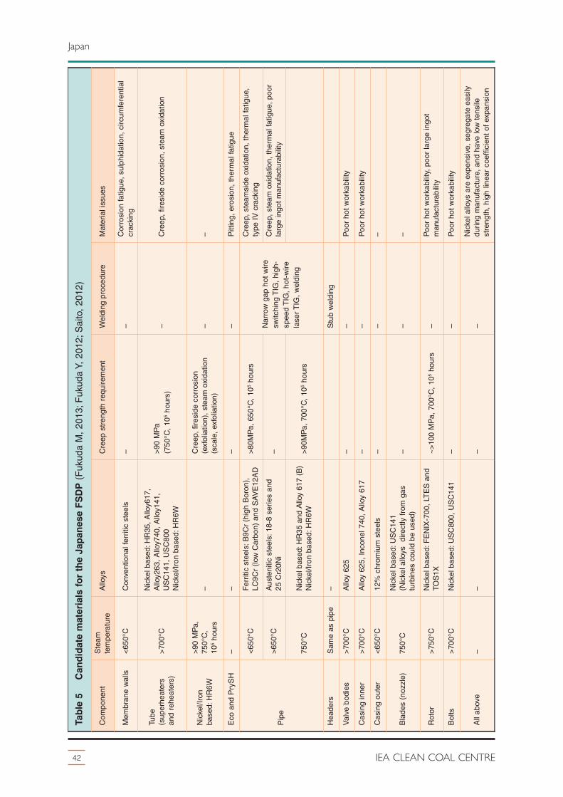
42 IEA CLEAN COAL CENTRE
Japan
Table 5 Candidate materials for the Japanese FSDP (
Fuk
uda
M,
2013
; Fuk
uda
Y, 2
012;
Sai
to,
2012
)
Com
pone
ntS
team
tem
pera
ture
Allo
ysC
reep
str
engt
h re
quire
men
tW
eldi
ng p
roce
dure
Mat
eria
l iss
ues
Mem
bran
e w
alls
<65
0°C
Con
vent
iona
l fer
ritic
ste
els
––
Cor
rosi
on fa
tigue
, su
lphi
datio
n, c
ircum
fere
ntia
lcr
acki
ng
Tube
(sup
erhe
ater
san
d re
heat
ers)
>70
0°C
Nic
kel b
ased
: HR
35,
Allo
y617
,A
lloy2
63,
Allo
y740
, A
lloy1
41,
US
C14
1, U
SC
800
Nic
kel/I
ron
base
d: H
R6W
>90
MP
a(7
50°C
, 10
5ho
urs)
–C
reep
, fir
esid
e co
rros
ion,
ste
am o
xida
tion
Nic
kel/I
ron
base
d: H
R6W
>90
MP
a,75
0°C
,10
5ho
urs
–C
reep
, fir
esid
e co
rros
ion
(exf
olia
tion)
, st
eam
oxi
datio
n(s
cale
, ex
folia
tion)
––
Eco
and
Pry
SH
––
––
Pitt
ing,
ero
sion
, th
erm
al fa
tigue
Pip
e
<65
0°C
Fer
ritic
ste
els:
B9C
r (h
igh
Bor
on),
LC9C
r (lo
w C
arbo
n) a
nd S
AV
E12
AD
>80
MP
a, 6
50°C
, 10
5ho
urs
Nar
row
gap
hot
wire
switc
hing
TIG
, hi
gh-
spee
d T
IG,
hot-
wire
lase
r T
IG,
wel
ding
Cre
ep,
stea
msi
de o
xida
tion,
the
rmal
fatig
ue,
type
IV
cra
ckin
g
>65
0°C
Aus
teni
tic s
teel
s: 1
8-8
serie
s an
d25
Cr2
0Ni
–C
reep
, st
eam
oxi
datio
n, t
herm
al fa
tigue
, po
orla
rge
ingo
t m
anuf
actu
rabi
lity
750°
CN
icke
l bas
ed: H
R35
and
Allo
y 61
7 (B
)N
icke
l/Iro
n ba
sed:
HR
6W>
90M
Pa,
700
°C,
105
hour
s
Hea
ders
Sam
e as
pip
e–
Stu
b w
eldi
ng
Val
ve b
odie
s>
700°
CA
lloy
625
––
Poo
r ho
t w
orka
bilit
y
Cas
ing
inne
r>
700°
CA
lloy
625,
Inc
onel
740
, A
lloy
617
––
Poo
r ho
t w
orka
bilit
y
Cas
ing
oute
r<
650°
C12
% c
hrom
ium
ste
els
––
–
Bla
des
(noz
zle)
750°
CN
icke
l bas
ed: U
SC
141
(Nic
kel a
lloys
di
rect
ly f
rom
gas
turb
ines
cou
ld b
e us
ed)
––
–
Rot
or>
750°
CN
icke
l bas
ed: F
EN
IX-7
00,
LTE
S a
ndTO
S1X
~
>10
0 M
Pa,
700
°C,
105
hour
s–
Poo
r ho
t w
orka
bilit
y, p
oor
larg
e in
got
man
ufac
tura
bilit
y
Bol
ts>
700°
CN
icke
l bas
ed: U
SC
800,
US
C14
1–
–P
oor
hot
wor
kabi
lity
All
abov
e–
––
–N
icke
l allo
ys a
re e
xpen
sive
, se
greg
ate
easi
lydu
ring
man
ufac
ture
, an
d ha
ve lo
w t
ensi
lest
reng
th,
high
line
ar c
oeffi
cien
t of
exp
ansi
on

The programme has gained sufficient information to create a P&ID for a double reheat AUSC PCCplant with a detailed list of candidate materials for critical components. The programme has developedthree new materials specifically for AUSC technology including FENIX700, USC141 andUSC800MOD.
There are plans in Japan to build a FSDP (600 MW at 700/720/720/35) from 2017 to 2021, withoperation and feedback from 2021 to 2026. The Japanese are assessing advanced ferritic heat resistantsteels in a separate project, which has pioneered work on boron-modified martensitic steels.
43Status of advanced ultra-supercritical pulverised coal technology
Japan
LPTVHPT
boiler
LP1 RH
HP1 RH 1 SHfurnace
4 SH2 SH HP2 RH
LP2 RH3 SH
ECO
HP-IPTsteam turbine
ferrite
austenite
conventional materials
ferrite
Ni-based
GT materials
ferrite
austenite
Ni-based
materials under development
35 MPag700°C
720°C 720°C
Figure 20 Flow diagram of a Japanese double reheat AUSC PCC plant (Fukuda, 2012a)

6 China
44 IEA CLEAN COAL CENTRE
In 2011, China had a total generating capacity of 1056 GW of which 765 GW was thermal power. thetotal generating capacity is forecast to reach 2380 GW in 2030, of which 1270 GW would be thermalpower. Through legislation and financial incentives, China is upgrading its entire fleet of coal-firedpower plant, replacing the old, small, inefficient and dirty units with new, large, efficient and cleanunits in order to sustain resources, minimise pollution and produce lower cost, reliable power. It is nosurprise therefore that China operates some of the cleanest and most efficient PCC plant. WaigaoqiawPCC plant has achieved a peak efficiency of 46.5% (net, LHV). Guodian Taizhou PCC plant is a newbuild with two 1000 MW double reheat USC units (600//610/610/31) aiming for an electricalefficiency of 47.6% (LHV, net) (Sun and others, 2012).
In July 2010, the National Energy Administration (NEA) launched the ‘National 700°C USC Coal-Fired Power Generation Technology Innovation Consortium’ whose principal aim is to develop andcommercialise AUSC technology. The NEA and the following 18 members are involved in theprogramme: Thermal Power Research Institute, Shanghai Power Equipment Research Institute,Institute of Metal Research of Chinese Academy of Science, China Iron and Steel Research InstituteGroup (CISRI), Electric Power Planning & Engineering Institute, China Power EngineeringConsulting Group Cooperation, Shanghai Electric, Dongfang Electric Corporation (DEC), HarbinElectric Corporation, China First Heavy Industries, China National Erzhong Group, Baoshan Iron &Steel, Dongbei Special Steel Group, Huaneng Group, China Datang Corporation, China HuadianCorporation, China Guodian Corporation and the China Power Investment Corporation (Sun andothers, 2012).
Figure 21 shows a Gantt chart of the Chinese research programme. The research programme has fivemain areas of study: identifying the critical high temperature components, material research,developing manufacturing capability for new alloys, operating a component testing facility followedby a FSDP (Sun and others, 2012).
The programme has a council that meets once a year to make the significant decisions. A committeemade up of experts arranges a workshop every six months to organise, guide and inspect theresearch projects, review achievements, propose new research and thus develop the technicalroadmap. The technical committee is sub-divided into four special working groups, which are thesystem and engineering solutions, boiler, turbine and material group (Sun and others, 2012;Liu, 2012).
Once a new project is proposed, members capable of completing the work apply for funding from thegovernment (NEA or the Ministry of Science and Technology). There is a secretariat which isresponsible for dealing with daily operations and arranging a meeting every three months. Figure 22shows the financing structure (Sun and others, 2012).
6.1 Ministry of Science and Technology
The Ministry of Science and Technology has set up a project called ‘Research on advanced boilers keypipes of USC thermal power units’. The project is co-ordinated by CISRI along with nine partners andhas received RMB29.5 million in funding to date. This project consists of three sub-projects (Sun andothers, 2012).� Manufacturing the boilers key pipes of 600–700°C USC unit: This sub-topic focuses on
selecting materials for the temperature range of 600–700°C in the demonstration plant; P92,P122, G115/G112, CCA617, Inconel740H are currently being assessed;
� Research on alloy GH2984 and its technology process used in 700°C USC thermal power
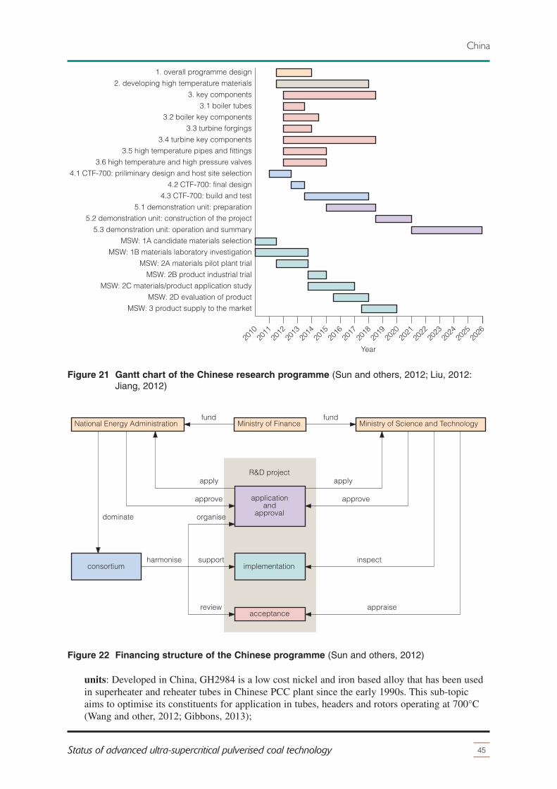
units: Developed in China, GH2984 is a low cost nickel and iron based alloy that has been usedin superheater and reheater tubes in Chinese PCC plant since the early 1990s. This sub-topicaims to optimise its constituents for application in tubes, headers and rotors operating at 700°C(Wang and other, 2012; Gibbons, 2013);
45Status of advanced ultra-supercritical pulverised coal technology
China
National Energy Administration Ministry of Science and TechnologyMinistry of Financefund fund
implementation
acceptance
applicationand
approval
R&D project
consortium
apply
approve
organise
support
review
apply
approve
dominate
harmonise inspect
appraise
Figure 22 Financing structure of the Chinese programme (Sun and others, 2012)
Year20
2620
1020
1120
2020
1920
2320
2120
2220
2420
1320
1220
1620
1420
1520
1720
1820
25
1. overall programme design
2. developing high temperature materials
3. key components
3.1 boiler tubes
3.2 boiler key components
3.3 turbine forgings
3.4 turbine key components
3.5 high temperature pipes and fittings
3.6 high temperature and high pressure valves
4.1 CTF-700: priliminary design and host site selection
4.2 CTF-700: final design
4.3 CTF-700: build and test
5.1 demonstration unit: preparation
5.2 demonstration unit: construction of the project
5.3 demonstration unit: operation and summary
MSW: 1A candidate materials selection
MSW: 1B materials laboratory investigation
MSW: 2A materials pilot plant trial
MSW: 2B product industrial trial
MSW: 2C materials/product application study
MSW: 2D evaluation of product
MSW: 3 product supply to the market
Figure 21 Gantt chart of the Chinese research programme (Sun and others, 2012; Liu, 2012:Jiang, 2012)
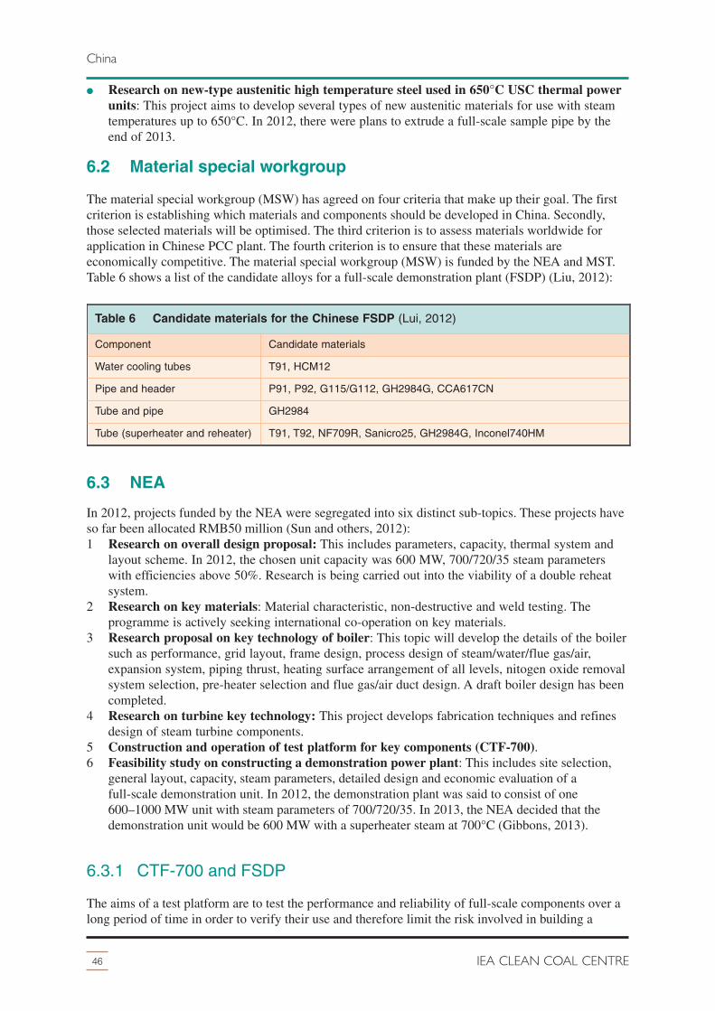
� Research on new-type austenitic high temperature steel used in 650°C USC thermal powerunits: This project aims to develop several types of new austenitic materials for use with steamtemperatures up to 650°C. In 2012, there were plans to extrude a full-scale sample pipe by theend of 2013.
6.2 Material special workgroup
The material special workgroup (MSW) has agreed on four criteria that make up their goal. The firstcriterion is establishing which materials and components should be developed in China. Secondly,those selected materials will be optimised. The third criterion is to assess materials worldwide forapplication in Chinese PCC plant. The fourth criterion is to ensure that these materials areeconomically competitive. The material special workgroup (MSW) is funded by the NEA and MST.Table 6 shows a list of the candidate alloys for a full-scale demonstration plant (FSDP) (Liu, 2012):
6.3 NEA
In 2012, projects funded by the NEA were segregated into six distinct sub-topics. These projects haveso far been allocated RMB50 million (Sun and others, 2012):1 Research on overall design proposal: This includes parameters, capacity, thermal system and
layout scheme. In 2012, the chosen unit capacity was 600 MW, 700/720/35 steam parameterswith efficiencies above 50%. Research is being carried out into the viability of a double reheatsystem.
2 Research on key materials: Material characteristic, non-destructive and weld testing. Theprogramme is actively seeking international co-operation on key materials.
3 Research proposal on key technology of boiler: This topic will develop the details of the boilersuch as performance, grid layout, frame design, process design of steam/water/flue gas/air,expansion system, piping thrust, heating surface arrangement of all levels, nitogen oxide removalsystem selection, pre-heater selection and flue gas/air duct design. A draft boiler design has beencompleted.
4 Research on turbine key technology: This project develops fabrication techniques and refinesdesign of steam turbine components.
5 Construction and operation of test platform for key components (CTF-700).6 Feasibility study on constructing a demonstration power plant: This includes site selection,
general layout, capacity, steam parameters, detailed design and economic evaluation of afull-scale demonstration unit. In 2012, the demonstration plant was said to consist of one600–1000 MW unit with steam parameters of 700/720/35. In 2013, the NEA decided that thedemonstration unit would be 600 MW with a superheater steam at 700°C (Gibbons, 2013).
6.3.1 CTF-700 and FSDP
The aims of a test platform are to test the performance and reliability of full-scale components over along period of time in order to verify their use and therefore limit the risk involved in building a
46 IEA CLEAN COAL CENTRE
China
Table 6 Candidate materials for the Chinese FSDP (Lui, 2012)
Component Candidate materials
Water cooling tubes T91, HCM12
Pipe and header P91, P92, G115/G112, GH2984G, CCA617CN
Tube and pipe GH2984
Tube (superheater and reheater) T91, T92, NF709R, Sanicro25, GH2984G, Inconel740HM

demonstration plant. The Clean Energy Research Institute, which is part of the Huaneng Group, isundertaking this project and plans to build a component test facility to operate at 700°C (CTF-700).The CTF-700 will be capable of reaching 725°C and 35 MPa with 3 kg/s of steam flow. A P&ID ofthe CTF-700 is shown in Figure 23. The CTF-700 will test an evaporator panel, superheater, header,large diameter pipe and valves. It will be installed in unit 2 of Huaneng Nanjing PCC plant (two pass,300 MW, 540°C and 25 MPa superheat steam). Materials tested will be those developed in China andpossibly foreign materials from other programmes. Tests will run for >100,000 hours (approximatelyeleven years) in order to verify performance (Jiang, 2012). As shown in Figure 21, the Chineseresearch programme aims to have an operational 600–660 MW FSDP in 2021 – after only elevenyears from the programme start date.
6.4 Future projects
In 2012 there were nine additional 700ºC material research topics preparing to apply for support fromgovernment national scientific research funds (Sun and others, 2012):1 boiler membrane wall technique;2 components of boiler superheater and reheater;3 research on boilers header;4 high temperature steam pipes and fittings;5 manufacturing technology of turbines HP-IP rotor;6 manufacturing technology of high temperature cylinder valve housing;7 turbines high temperature blades and fasteners, valve cores wear resisting components;8 high temperature turbine forgings;9 high temperature turbines castings.
6.5 Plant configuration
The cross compound at high/low position arrangement (CCHLPA) of the steam turbine is where theHP and IP turbines are both mounted at the same level as the boiler steam headers and the LP turbineremains at ground level – this is shown in Figure 24. The CCHLPA reduces the pipework length,which reduces cost the pressure drop. A 1350 MWe unit with double reheat and CCHLPA operating atUSC steam parameters (600/620/610/30) is estimated to reach 48.92% net efficiency (Mao, 2012).
6.6 Summary
Starting in 2010, the Chinese programme is supported by nineteen organisations. Despite the recentstart of this research programme, substantial progress has been made. The majority of laboratory
47Status of advanced ultra-supercritical pulverised coal technology
China
second-stageplaten
superheaterinlet
last-stagesuperheateroutlet
first-stagereheateroutlet
evaporativepanel
spray desuperheat
610°C25 MPa
725°C25 MPa484°C
25 MPa
superheatsection
545°C25 MPa
436°C4.6 MPa
safetyvalve725°C turbine
inletvalve
turbine bypass valve
Figure 23 P&ID of the Chinese CTF-700 (Jiang, 2012)

testing will finish in 2014-15. In 2012, a list of candidate materials for the critical components in theboiler was established with some materials developed in China, the steel G115/G112 developed byCISRI and nickel/iron alloy GH2984/GH2984G developed by the Institute of Metal Research ofChinese Academy of Science. Alternative plant configuration to minimise the length of the pipeworkhas been found with the cross compound at high/low position arrangement (CCHLPA). Manufacturingof large-scale components and construction of a CTF started in mid-2013 and a FSDP is planned to beoperational in 2021; this is only eleven years from the start of the programme. The FSDP will be600 MW at 700/35 with a possibility of double reheat and CCHLPA.
48 IEA CLEAN COAL CENTRE
China
IP2a+IP2b+LP
HP+IP1
LP arrangement
HP/IP arrangement
inletoutlet
Figure 24 CCHPLA (Mao, 2012)

7 Russia
49Status of advanced ultra-supercritical pulverised coal technology
Russia has one of the largest reserves of coal in the world; however the prominence of coal power inRussia has been declining since the 1990s. There is a partnership between the private and publicsectors which has set up a research programme for cleaner and more efficient power from coal called‘Foundation: Energy without Borders’. The partners are the Ministry of Energy, the Institutes ofDevelopment (Vnesheconombank, Rosnano and Russian Venture Company), the Ministry ofEducation and Science and the Ministry of Industry and Trade. Within the Foundation: Energywithout Borders programme (Portfolio 1, Action 1) AUSC is a key technology aiming at 51–53% netefficiency with steam parameters 700/720/35. Research in Russia has previously tested steels for useup to 650°C. Inter RAO are researching steels for use in AUSC technology. Austenitic steels12Cr18H12T and 10Cr16H16B2MBR are being developed for heating surfaces and martensitic steels10X9MFB, 10Cr9B2MFBR, 10Cr9K3B2MFBR AND 12Cr10M1V1FBR are currently ondevelopment for the pipes and rotors. Figure 25 shows a diagram of a possible CTF by theAll-Russian Thermal Engineering Institute. The programme is open for collaboration both on abilateral and multilateral basis (Rogalev, 2012).
stand for turbine test
stand for metal test
test armoured camera
furnace for increasingtemperature of steam
steam superheater of boiler
GS = 25 t/h
GS = 5 t/htS = 600°CPS = 30.0 MPa
steam to stand
fuel, air
tS = 800°CPS = 30.0 MPa
valve for test
PRDS
tS = 510°CPS = 9.0 MPa
HE for coolingflue gas
Figure 25 P&ID of the Russian CTF (Rogalev, 2012)

8 India
50 IEA CLEAN COAL CENTRE
Coal is India’s largest fossil energy reserve, at 293 Gt and an annual consumption in 2012 of0.5%Gt – power from coal is expected to rise to 320 GW in 2031. The Indian government have aprogramme called the ‘the AUSC project’ under the ninth National Mission on Clean CoalTechnologies in keeping with the National Action Plan for Climate Change.
The Indian Material Research Programme was initiated in 2008 and was estimated to cost at leastRS6,000–10,000 CRORE. The programme is being funded and undertaken by a joint venture betweenthe research institute Indira Gandhi Centre for Atomic Research (IGCAR), the equipmentmanufacturer Bharat Heavy Electrical (BHEL) and the power generating company National ThermalPower Corporation (NTPC). IGCAR will develop the materials, Misra Dhatu Nigam and BHEL willdesign, manufacture, and commission the equipment and NTPC will construct the test loop anddemonstration unit.
IGCAR will design and develop new ‘70% nickel alloys’ capable of 710°C and 35 MPa superheatersteam parameters, raising net efficiency from 38–40% to 46% (LHV) and reducing carbon dioxideemissions by 15–20%. IGCAR have experience with new nickel alloys through its prototype ‘fastbreeder’ nuclear reactor project. Materials include Super 304H, Inconel 617, Haynes 230, T92 andT91.
BHEL will manufacture and commission the demonstration unit and NTPC will operate it.Components for USC plant in India are often purchased from other countries – indigenouscommercialisation of AUSC technology has a large potential market. In 2013, BHEL submitted theproject design memorandum for an 800 MW AUSC boiler, including technical and economic details,to the office of the Principal Scientific Adviser of the Government of India. The Welding ResearchInstitute (WRI) at BHEL are studying new welding techniques such as GTAW. The Hyderabad-basedpublic sector Misra Dhatu Nigam will help fabricate the new nickel alloys.
New high temperature components will be tested in a component test facility (CTF) at the NTPC210 MW unit in Dadri PCC plant in Uttar Pradesh. Providing successful completion of a CTF,operation of a demonstration unit is planned to start in 2018 and is likely to be based at the NTPCDadri complex (The Hindu, 2013a,b; The Hindu Business Line 2013; The Economic Times, 2010).
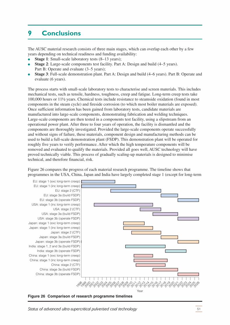
9 Conclusions
51Status of advanced ultra-supercritical pulverised coal technology
The AUSC material research consists of three main stages, which can overlap each other by a fewyears depending on technical readiness and funding availability:� Stage 1: Small-scale laboratory tests (8–13 years);� Stage 2: Large-scale components test facility. Part A: Design and build (4–5 years).
Part B: Operate and evaluate (3–5 years);� Stage 3: Full-scale demonstration plant. Part A: Design and build (4–6 years). Part B: Operate and
evaluate (6 years).
The process starts with small-scale laboratory tests to characterise and screen materials. This includesmechanical tests, such as tensile, hardness, toughness, creep and fatigue. Long-term creep tests take100,000 hours or 11½ years. Chemical tests include resistance to steamside oxidation (found in mostcomponents in the steam cycle) and fireside corrosion (to which most boiler materials are exposed).Once sufficient information has been gained from laboratory tests, candidate materials aremanufactured into large-scale components, demonstrating fabrication and welding techniques.Large-scale components are then tested in a components test facility, using a slipstream from anoperational power plant. After three to four years of operation, the facility is dismantled and thecomponents are thoroughly investigated. Provided the large-scale components operate successfullyand without signs of failure, these materials, component design and manufacturing methods can beused to build a full-scale demonstration plant (FSDP). This demonstration plant will be operated forroughly five years to verify performance. After which the high temperature components will beremoved and evaluated to qualify the materials. Provided all goes well, AUSC technology will haveproved technically viable. This process of gradually scaling-up materials is designed to minimisetechnical, and therefore financial, risk.
Figure 26 compares the progress of each material research programme. The timeline shows thatprogrammes in the USA, China, Japan and India have largely completed stage 1 (except for long-term
Year20
0520
2619
9819
9920
0020
0120
0220
0320
0420
1120
0620
0720
0820
0920
1020
1320
1220
1620
1420
1520
17
EU: stage 1 (exc long-term creep)
EU: stage 1 (inc long-term creep)
EU: stage 2 (CTF)
EU: stage 3a (build FSDP)
EU: stage 3b (operate FSDP)
USA: stage 1 (inc long-term creep)
USA: stage 2 (CTF)
USA: stage 3a (build FSDP)
USA: stage 3b (operate FSDP)
Japan: stage 1 (exc long-term creep)
Japan: stage 1 (inc long-term creep)
Japan: stage 2 (CTF)
Japan: stage 3a (build FSDP)
Japan: stage 3b (operate FSDP)
India: stage 1, 2 and 3a (build FSDP)
India: stage 3b (operate FSDP)
China: stage 1 (exc long-term creep)
China: stage 1 (inc long-term creep)
China: stage 2 (CTF)
China: stage 3a (build FSDP)
China: stage 3b (operate FSDP)
2021
2018
2019
2020
2023
2022
2024
2025
Figure 26 Comparison of research programme timelines

creep tests) and are progressing towards stage 2. The European programme is still at stage 2 afterencountering technical difficulties. By 2018, results from stages 1 and 2 will provide enough technicaldata to decide further progression of the technology to stage 3. FSDP are planned to begin operationin 2021, operation will last for five years in order to qualify the materials and verify the technologyperformance. Table 7 compares the steam parameters and capacity the FDSP and possible commercialplant for each programme. Providing the FSDP operates successfully, the commercial plant will be ofsimilar size, as scaling the technology up is risky. The electrical efficiency of a commercial unit willdepend largely on its location and whether it has single or double number of – it could reach 52%.
Each major research programme is assessing a slightly different set of candidate materials. This islargely due to different requirements for the boiler materials as the fireside corrosion mechanisms varyaccording to the type of coal fired and whether biomass and waste are cofired. The candidate materialsfor all programmes are similar. Low cost and proven ferritic steels (such as grade 23) are employed incomponents exposed to steam temperatures below 550°C (such as the membrane walls and part of thesteam turbine rotors and casing). Proven state-of-the-art 9–12% chromium martensitic steels (such asgrade 92) are used in components exposed to steam temperatures of 550–625°C (such as superheaters,reheater and headers, valve, casing and pipes). Austenitic steels (such as HR3C and Sanicro 25) canbe used for superheater and reheater applications only with steam up to 625°C; and may be suitablefor up to 700°C. The new generation of mostly unqualified nickel alloys (such as nickel alloy 617, 625and 740) is expected to be applied in thin and thick-section components at temperatures above 630°C.To maintain economic favourability, most research programmes are improving steels to fill in thetemperature gap between 625°C and 650°C. New nickel and nickel/iron alloys have been developed inAsia specifically for AUSC technology. Coatings are being assessed in most programmes but with notangible benefits to date. Japan is proposing to retrofit AUSC technology to older plant. The cycliccapability of AUSC technology is being assessed as it is important in the USA and EU. Table 8summarises the research topics in each programme.
High temperature material research programmes have produced valuable research spin-offtechnologies for existing PCC plant. For example, alternative plant configurations for coal-fired powerplant to reduce capital expenditure and improve steam cycles which can be retrofitted and raiseelectrical efficiency. Improved steels will be used in more flexible and slightly higher temperatureultra-supercritical technology.
Collaboration between the material research programmes could hasten research progress throughknowledge sharing and increased finances. For example, a common material database containinginformation on mechanical tests, such as long-term creep tests, and resistance against chemical attackwill facilitate all research programmes. In 2012, the National Energy Administration (NEA) in China
52 IEA CLEAN COAL CENTRE
Conclusions
Table 7 Comparison of full-scale demonstration plant details
EU USA Japan China
Steam loops Yes Yes Yes Yes
Component test facility
Full-scale demonstration plant capacity,MWe
500 350–-1000 600 600–660
Full-scale demonstration plant steamparameters, °C/°C/MPa
705/720/35 700/730/35 700 700/720/35
Estimated full-scale capacity, MWe 500–1000 550-1100 600 600
Estimated full-scale steam parameters,°C/°C/MPa
705/720/35700–730/730–760/35
700/720/720/35
700/720/35
Estimated full-scale efficiency, %, net,hard coal
>50 (LHV) 45–47 (HHV) 46–50 (LHV) >50 (LHV)

was actively seeking international collaboration on key materials and programme the in Russia is openfor collaboration. One of the purposes of this report is help initiate collaboration.
Global research is proving that nickel alloys can operate at advanced ultra-supercritical (AUSC)parameters in pulverised coal combustion (PCC) plant. PPC plant operating at AUSC steamparameters are estimated to reach electrical efficiencies of 50% (net, LHV, hard coal). A higherefficiency not only reduces coal consumption and emissions for a given amount of coal but alsolowers the cost of potential CCS (carbon capture and storage) technology.
Increasing the superheater steam temperature will continue to provide gains in electrical efficiency.However this trend will diminish at 900°C (as this is where the Carnotisation gap almost closes)reaching electrical efficiencies of over 60%. Therefore, AUSC technology would be the first of manygenerations of higher steam parameters that utilise super alloys.
A commercial unit could be brought online in 2031, providing the material research programmesproceeds as planned, and the time frame for a new build PCC plant is four years. However, thecommercialisation of AUSC technology will then rest entirely on the economics, which depend onvariable factors, such as the future value of coal, cost of nickel alloys and the carbon tax.
53Status of advanced ultra-supercritical pulverised coal technology
Conclusions
Table 8 Comparison of research topics
Research topic EU USA Japan China
Retrofit to older units No No Yes No
Cyclic operation Yes Yes No No
Oxyfuel Yes No No No
High sulphur coal firing on firesidecorrosion
No Yes No No
Biomass cofiring on fireside corrosion Yes No Yes No
Waste cofiring on fireside corrosion Yes No No No
Coatings Yes Yes Yes No
New 650°C steels Yes, MARBN Yes Yes, MARBNYes,G115/G112
New nickel/iron alloys No NoYes,FENIX700
Yes, GH2984
New nickel alloys No NoYes, USC141andUSC800MOD
No
Welded rotors Yes Yes Yes Yes
Alternative plant configurationYes, CompactDesign, InlineArrangement
No No Yes, CCHLPA
Improved steam cycle Master Cycle Topping Cycle No No
10 References
54 IEA CLEAN COAL CENTRE
Allen D, Du H, Vanstone R, Moody P, Barnard P, Roberts S, Maclachlan R and Thomson R(2013) The ‘IMPACT’ project – development of ‘MARBN’ steel for next generation steam plant.Paper presented at: Second workshop on upgrading and efficiency improvements in coal-fired powerplant, Nottingham, UK, 19-20 Mar 2013; 25 pp (2013)Breeze P (2012) Pushing the steam cycle boundaries. Power Engineering International; 20 (4);17-20 (Apr 2012)Cieszynski K, Kaczorowski M (2012) Boiler design at ultra supercritical steam parameters(653ºC/672ºC – 303/60 bar). Paper presented at: Advanced ultrasupercritical coal-fired power plants,Vienna, Austria, 19-20 Sep 2012. Available from:http://ausc.coalconferences.org/ibis/ausc.coalconferences/home; 12 pp (2012COMTES700 (2013) COMTES700 website www.comtes700.org/index.xhtml; (accessed Apr 2013)COORETEC (2013) COORETEC website www.cooretec.de; (accessed Apr 2013)CRESTA (2013) New creep resistant stable steel for USC power plant website. Available atwww.cresta.cc; (accessed Aug 2013)Feng W, Yu X (2012) Challenging the efficiency limitation of the existing coal-fired powertechnology. Paper presented at: Upgrading and efficiency improvements in coal-fired power plants,Melbourne, Vic, Australia, 19-20 Apr, 2012. Available from:http://upgrading.coalconferences.org/ibis/Upgrading-workshop/my-event; 14 pp (2012)Fukuda M (2012a) Advanced USC technology development in Japan. Paper presented at: Advancedultrasupercritical coal-fired power plants, Vienna, Austria, 19-20 Sep 2012. Available from:http://ausc.coalconferences.org/ibis/ausc.coalconferences/home; 15 pp (2012)Fukuda Y (2012b) High temperature corrosion and steam oxidation of candidate materials for 700Cclass A-USC. Paper presented at: Advanced ultrasupercritical coal-fired power plants, Vienna,Austria, 19-20 Sep 2012. Available from:http://ausc.coalconferences.org/ibis/ausc.coalconferences/home; 15 pp (2012)Gazzino M (2012) ENCIO project: overview, status up-date and planned fireside corrosion tests.Paper presented at: Advanced ultrasupercritical coal-fired power plants, Vienna, Austria, 19-20 Sep2012. Available from: http://ausc.coalconferences.org/ibis/ausc.coalconferences/home; 16 pp(2012)Gibbons TB (2013) Recent advances in steels for coal fired power plant: a review. Transactions ofthe Indian Institute of Metals; in press 1-10 (2013)Gierschner G, Ullrich C, Tschaffon H (2012) Latest developments for the flexible high efficientpower plant of the future. Paper presented at: Advanced ultrasupercritical coal-fired power plants,Vienna, Austria, 19-20 Sep 2012. Available from:http://ausc.coalconferences.org/ibis/ausc.coalconferences/home; 21 pp (2012)Grab T, Stahl F (2012) Welding of heavy wall pipes made from high temperature alloys, specialrequirements and welding procedures. Paper presented at: 1st International VDI conference on alloysin power plant technology, Berlin, Germany, 15-16 Jun 2012; 12 pp (2012)Hagen I, Bendick W (2013) Creep resistant ferritic steel for power plants from MannesmannForschungsinstitut GmbH. Available at: www.cbmm.com.br/portug/sources/techlib/science_techno/table_content/sub_4/images/ pdfs/040.pdf; 24 pp, (accessed Aug 2013)Henderson C (2013) IEA Clean Coal Centre, London, UK, private communication (Sep 2013)Henderson C (2004) Understanding coal-fired power plant cycles. CCC/91, London, UK, IEAClean Coal Centre, 47 pp (Oct 2004)Hernblom J (2012) Properties of advanced high strength austenitic alloy Sanicro 25 developed forA-USC plants. Presented at: Advanced ultrasupercritical coal-fired power plants, Vienna, 19-20 Sep2012. Available from: http://ausc.coalconferences.org/ibis/ausc.coalconferences/home; 20 pp (2012)Holcomb G R (2013) Ultra-supercritical steam corrosion. Available at:www.netl.doe.gov/publications/proceedings/03/materials/manuscripts/Holcomb_m2.pdf; 6 pp, (accessed Aug 2013)

Holmström S, Auerkari P (2012) Material and component requirements in existing and new plants.Paper presented at: 1st International VDI conference on alloys in power plant technology, Berlin,Germany, 15-16 Jun 2012; 15 pp (2012)IEA (2012) IEA high efficiency, low emissions (HELE) coal roadmap. IEA, Paris, France; 42 pp(2012)IEA Clean Coal Centre (2012) Coal power database. London, UK, IEA Clean Coal Centre (2012)Imano S (2012) Development of Ni-base super alloys for A-USC power plant with temperaturecapability 800ºC. Paper presented at: Advanced ultrasupercritical coal-fired power plants, Vienna,Austria, 19-20 Sep 2012. Available from:http://ausc.coalconferences.org/ibis/ausc.coalconferences/home; 18 pp (2012)Jedamzik M D (2012) 700C steam generator technology – HPE activities and scope of work inR&D projects. Paper presented at: Advanced ultrasupercritical coal-fired power plants, Vienna,Austria, 19-20 Sep 2012. Available from:http://ausc.coalconferences.org/ibis/ausc.coalconferences/home; 32 pp (2012)Jiang J (2012) Component test facility project in China. Paper presented at: Advancedultrasupercritical coal-fired power plants, Vienna, Austria, 19-20 Sep 2012. Available from:http://ausc.coalconferences.org/ibis/ausc.coalconferences/home; 21 pp (2012)KMM-VIN (2013) Newsletters. Available at www.kmm-vin.eu/node/83 (accessed Aug 2013)Kranzmann A, Olbricht J, Skrotzki B (2012) Concepts for complementary materials testingsimulating the service conditions of high efficiency power plants. Paper presented at: Advancedultrasupercritical coal-fired power plants, Vienna, Austria, 19-20 Sep 2012. Available from:http://ausc.coalconferences.org/ibis/ausc.coalconferences/home; 18 pp (2012)Kuhn B, Talik M, Li C, Zurek J, Quadakkers W J, Beck T, Singheiser L (2012) Development ofcreep- and corrosion-resistant steels for future steam power plants. Paper presented at: 1stInternational VDI conference on alloys in power plant technology, Berlin, Germany, 15-16 Jun 2012;10 pp (2012)Liu Z (2012) The research and development of heat resistant steels and alloys used for 700CA-USC-PP in China. Paper presented at: Advanced ultrasupercritical coal-fired power plants, Vienna,Austria, 19-20 Sep 2012. Available from:http://ausc.coalconferences.org/ibis/ausc.coalconferences/home; 7 pp (2012)MACPLUS (2013) MACPLUS project website www.macplusproject.eu/home (accessed Aug 2013)Maile K (2012) High temperature materials for advanced fossil fired plants. Paper presented at: 1stInternational VDI conference on alloys in power plant technology, Berlin, Germany, 15-16 Jun 2012;12 pp (2012)Maile K, Metzger K (2012) GKM test rig – HWT I, HWT II: Qualification of materials for 700°Cpower plant. Paper presented at: 1st International VDI conference on alloys in power planttechnology, Berlin, Germany, 15-16 Jun 2012; 12 pp (2012)Mao J, Feng W (2012)Ways to further improve efficiency for ultra-supercritical coal-fired powerplants in China. Paper presented at: Advanced ultrasupercritical coal-fired power plants, Vienna,Austria, 19-20 Sep 2012. Available from:http://ausc.coalconferences.org/ibis/ausc.coalconferences/home; 9 pp (2012)Marion J L (2012) Advance ultrasupercritical steam power plant. Paper presented at: Advancedultrasupercritical coal-fired power plants, Vienna, Austria, 19-20 Sep 2012. Available from:http://ausc.coalconferences.org/ibis/ausc.coalconferences/home; 28 pp (2012)Mayer K H (2001) New ferritic steels for advanced power stations. In: BALTICA V, 5th internationalconference on condition and life management for power plants, Porvoo, Finland, 6-8 Jun 2001. VTTsymposium 211, Espoo, Finland, VTT Information Service, vol 1, pp 11-33 (2001)McCauley K (2012) Technical readiness for A-USC plant deployment – a B&W perspective. Paperpresented at: Advanced ultrasupercritical coal-fired power plants, Vienna, Austria, 19-20 Sep 2012.Available from: http://ausc.coalconferences.org/ibis/ausc.coalconferences/home; 14 pp (2012)McCoy S A, Holmes T, Baker B A, Gollihue R D, deBarbadillo J J, Maitra D B (2013)Characterisation of age-hardenable superalloy INCONEL alloy 740H for advanced ultra supercriticalservice Paper presented at: Sixth international conference on clean coal technologies, Thessaloniki,Greece, 12-16 May 2013; 30 pp (2013)
55Status of advanced ultra-supercritical pulverised coal technology
References

Modern Power Systems (2008) AD700 innovations pave the way for 53 per cent efficiency. ModernPower Systems; 28 (11); 15-20 (Nov 2008)Mohrmann R, Stolzenberger C G (2012) Demands on materials and components for existing andnew conventional power plants. Paper presented at: Advanced ultrasupercritical coal-fired powerplants, Vienna, Austria, 19-20 Sep 2012. Available from:http://ausc.coalconferences.org/ibis/ausc.coalconferences/home; 17 pp (2012)Moreea-Taha R (2002) Materials development for coal, biomass and waste fuel plants. CCC/61,London, UK, IEA Clean Coal Centre, 58 pp (Aug 2002)Morrison G (2011) The energy balance as the 21st century unfolds and the role of coal.Presentation at: European power generation strategy summit, Prague, Czech Republic, 29 Nov2011; 50 pp (2011)Nalbandian H (2008) Performance and risks of advanced pulverised coal plant. CCC/135, London,UK, IEA Clean Coal Centre, 70 pp (May 2008)National Coal Council (2007) Technologies to reduce or capture and store carbon dioxideemissions. Washington, DC, USA, The National Coal Council, 178 pp (Jun 2007)NDT Resource Center (2013) www.ndt-ed.org/index_flash.htm (accessed Aug 2013)Nippon Steel and Sumitomo Metal (2013) Fossil fuel power material database. Available at:www.tubular.nssmc.com/product-services/specialty-tube/tube-application/fossil-fuel-power(accessed Aug 2013)Osgerby S (2007) Mat UK energy materials review: R&D priorities for steam turbine based powergeneration, Version 1.2. London, UK, Alstom Power, 11 pp (3 Aug 2007)Phillips J (2011) US program for advanced ultrasupercritical (A-USC) coal fired power plants.Webinar from the McIlvaine Company. Available at:www.mcilvainecompany.com/Decision_Tree/subscriber/Tree/DescriptionTextLinks/Jeffrey%20Phillips%20-%20EPRI%20-%203-24-11.pdf (Mar 2013)Phillips J (2012) The US Department of Energy project on advanced materials for boilers and steamturbines. Paper presented at: Upgrading and efficiency improvements in coal-fired power plants,Melbourne, Vic, Australia, 19-20 Apr, 2012. Available from:http://upgrading.coalconferences.org/ibis/Upgrading-workshop/my-event; 17 pp (2012)Rogalev N D (2012) Foundation: energy without orders and its R&D program. Presentation at:Advanced ultrasupercritical coal-fired power plants, Vienna, Austria, 19-20 Sep 2012. Availablefrom: http://ausc.coalconferences.org/ibis/ausc.coalconferences/home; 11 pp (2012)Romanosky R (2012) A comprehensive overview of the United States advanced ultrasupercritical(USC) materials research program. Presentation at: Advanced ultrasupercritical coal-fired powerplants, Vienna, 19-20 Sep 2012. Available from:www.ausc.coalconferences.org/ibis/ausc.coalconferences/home; 18 pp (2012)Saito E (2012) One of the concrete action plans which supply 700C class A-USC technology to acoal fired power market. Paper presented at: Advanced ultrasupercritical coal-fired power plants,Vienna, Austria, 19-20 Sep 2012. Available from:http://ausc.coalconferences.org/ibis/ausc.coalconferences/home; 21pp (2012)Shingledecker J (2012) U.S. program on advanced ultrasupercritical power plant materials – theeconomy of using advanced alloys. Paper presented at: Advanced ultrasupercritical coal-fired powerplants, Vienna, Austria, 19-20 Sep 2012. Available from:http://ausc.coalconferences.org/ibis/ausc.coalconferences/home; 18 pp (2012)Sobczak N, Pirowski Z, Purgert R M, Uhl W, Jaskowiec K, Sobczak J (2012) Castability ofHAYNES 282 alloy. Presentation at: Advanced ultrasupercritical coal-fired power plants, Vienna,19-20 Sep 2012. Available from: http://ausc.coalconferences.org/ibis/ausc.coalconferences/home;24 pp (2012)Scott D H (2001) Improving the competitiveness of next generation coal-fired plants. CCC/52,London, UK, IEA Coal Research, 48 pp (Sep 2001)Stam A (2012) NextGenPower. Paper presented at: Advanced ultrasupercritical coal-fired powerplants, Vienna, Austria, 19-20 Sep 2012. Available from:www.ausc.coalconferences.org/ibis/ausc.coalconferences/home; 29 pp (2012)Starkey M (2013) Bromsgrove, UK, Metstar Consulting, private communication (Aug 2013)
56 IEA CLEAN COAL CENTRE
References

Stein-Brzozowska G (2012) Fireside corrosion of dedicated austenitic steels in ultra-supercriticalcoal-fired power plant. Paper presented at: Advanced ultrasupercritical coal-fired power plants,Vienna, Austria, 19-20 Sep 2012. Available from:http://ausc.coalconferences.org/ibis/ausc.coalconferences/home; 25 pp (2012)Stultz S C, Kitto J B (eds) (2005) Metallurgy, materials and mechanical properties. In: Steam: itsgeneration and use. 41th edition. Barberton, CO, USA, Babcock and Wilcox Co, pp 7/1-7/25 (2005)Subanovic M, Schneider A (2012) Creep-resistant steels for high temperature applications inconventional power plants. Paper presented at: 1st International VDI conference on alloys in powerplant technology, Berlin, Germany, 15-16 Jun 2012; 14 pp (2012)Sun R, Cui Z, Tao Y (2012) Development of 700C USC coal-fired power generation technology inChina. Paper presented at: Advanced ultrasupercritical coal-fired power plants, Vienna, Austria,19-20 Sep 2012. Available from: http://ausc.coalconferences.org/ibis/ausc.coalconferences/home;10 pp (2012)Sven K (2001) The advanced super critical 700°C pulverized coal-fired power plant. Paper presentedat: VGB congress power plants 2001, Brussels, Belgium, 10-12 Oct 2001; 9 pp (2001)The Economic Times (2010) IGCAR to develop advanced boiler for coal-fired power plants.Available at: www.articles.economictimes.indiatimes.com/keyword/kalpakkam/recent/2; (7 Sep 2010)The Hindu (2013b) BHEL readies design for 800 MW plant with ultra supercritical parameters.Available at: www.thehindu.com/todays-paper/tp-national/tp-tamilnadu/bhel-readies-design-for-800-mw-plant-with-ultra-supercritical-parameters/article4636067.ece; (20 Apr 2013)The Hindu (2013a) WRI carries out study for fabrication of ultra super critical boilers. Available at:www.thehindu.com/news/cities/Tiruchirapalli/article3857944.ece; (4 Sep 2013)The Hindu Business line (2013) BHEL-NTPC-IGCAR effort to boost efficiency of power plants.Available at: www.thehindubusinessline.com/companies/bhelntpcigcar-effort-to-boost-efficiency-of-power-plants/article4603180.ece; (10 Apr 2013)VGB (2012a) Electricity generation – facts and figures. Available fromwww.vgb.org/en/data_powergeneration; 28 pp (Dec, 2012)VGB (2012b) Pre-engineering study ‘NRW Power Plant 700°C’ NRWPP700. Berlin, Germany, VGBPowerTech e.V.; 112 pp (Jan 2012)VGB (2013a) KOMET 650. Available from; www.vgb.org/en/komet650_download; 36 pp (Mar 2013)VGB (2013b) Power plant technologies. Available from: www.vgb.org/en/research_fossil; Apr, 2013Viswanathan V, Purgert R, Rawls P (2008b) Coal-fired power materials part II. AdvancedMaterials & Processes; 166 (9); 47-49 (Sep 2008)Viswanathan V, Purgert R, Rawls P (2008a) Coal-fired power materials. Advanced Materials &Processes; 166 (8); 47-49 (Aug 2008)Viswanathan R, Armor A F, Booras G (2004) A critical look at supercritical power plants. Power,New York; 148 (3); 42-49 (Apr 2004)Wang C S, Wang T T, Zhao H Q, Guo J T, Zhou L Z (2012) Optimization of microstructure andmechanical properties of Ni-Fe-based super alloy GH984. Paper presented at: Advancedultrasupercritical coal-fired power plants, Vienna, Austria, 19-20 Sep 2012. Available from:http://ausc.coalconferences.org/ibis/ausc.coalconferences/home; 19 pp (2012)Wilde M (2012) European Union research activities and new approach on international cooperation.Paper presented at: Advanced ultrasupercritical coal-fired power plants, Vienna, Austria, 19-20 Sep2012. Available from: http://ausc.coalconferences.org/ibis/ausc.coalconferences/home; 11pp (2012)Zanin E (2013) Material-component performance-driven solutions for long-term efficiency increasein ultra supercritical power plants. Paper presented at: Second workshop on upgrading and efficiencyimprovements in coal-fired power plant, Nottingham, UK, 19-20 Mar 2013; 29 pp (2013)
57Status of advanced ultra-supercritical pulverised coal technology
References