Embed Size (px)
Citation preview
DISTRIBUTION STATEMENT A. Approved for public release; distribution is unlimited.
Cynthia P. Romo & Dr. Josephine Covino
STATUS - CRITICAL DIAMETER AND GAP TESTS FOR HAZARD CLASSIFICATION OF SOLID ROCKET MOTORS
Insensitive Munitions and Energetic Materials Technology Symposium 23 – 26 April 2018
Portland, OR
K.P. Ford, A.D. Farmer, R. Rose Naval Air Warfare Center Weapons Division, China Lake, California
T.L. Boggs, A.I. Atwood Naval Systems Incorporated, Ridgecrest, California
Distribution Statement A: Public Release
• Brief history of propellants – How formulations have changed with time
• Development of the gap test – Determine transportation and storage hazard classification
• Overview of current test procedures
• Options available to the system developer – Strengths and weaknesses of each option
• Facilitate dialogue on methods to improve gap testing
2
Distribution Statement A: Public Release
• World War II – Early 1950s: Double-base propellants – Small critical diameters
• 1950’s – 1960’s: Composite Propellants – AP/Al/binder replaced many NC/NG formulations – Critical diameter increased markedly
• Proliferation of AP based systems
• 1970’s: Improving propellant compositions – Adding nitramines to increase specific impulse
• Range, velocity, and payload – Burning rate modifiers
• Decrease time to target – Increased performance – decreased critical diameter
3
Distribution Statement A: Public Release
• Shock initiation test (1950) • Predict hazard from unintentional
detonation – One explosive exposed to shock – Quantify the sensitivity of the material
• Los Alamos National Lab small-scale gap test
• Naval Ordnance Lab large-scale gap test (NOL LSGT)
• Super large-scale gap test (SLSGT)
4
Distribution Statement A: Public Release
• AP/Al/binder propellants – Critical diameter in multiple feet
• Project SOPHY: dcr greater than 62 inches
– Industry stopped determining critical diameter • Hard to find large mechanical shock threat
• Reduce the hazard classification of a system propellant from HD 1.1 to HD1.3 – Add nitramines until a “go” reaction, then
decrease nitramine content until “no-go” • Larger gap tests needed
5
Distribution Statement A: Public Release
• NOL LSGT and newer formulations – Could not help characterize large solid rocket
motor hazard
• Modification of the Technical Bulletin 700-2 – UN Test Series 6
• Used for hazard classification HD1.1, 1.2,1.3, and 1.4 • Single package test – UN Test 6 (a) • Stack test – UN Test 6 (b)
– Alternate tests • Performed on large solid propellant rocket motors – very
expensive
6
Distribution Statement A: Public Release
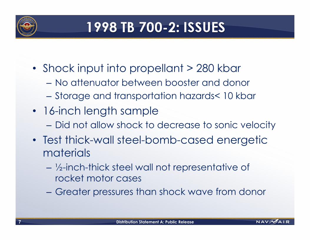
• Shock input into propellant > 280 kbar – No attenuator between booster and donor – Storage and transportation hazards< 10 kbar
• 16-inch length sample – Did not allow shock to decrease to sonic velocity
• Test thick-wall steel-bomb-cased energetic materials – ½-inch-thick steel wall not representative of
rocket motor cases – Greater pressures than shock wave from donor
7
Distribution Statement A: Public Release
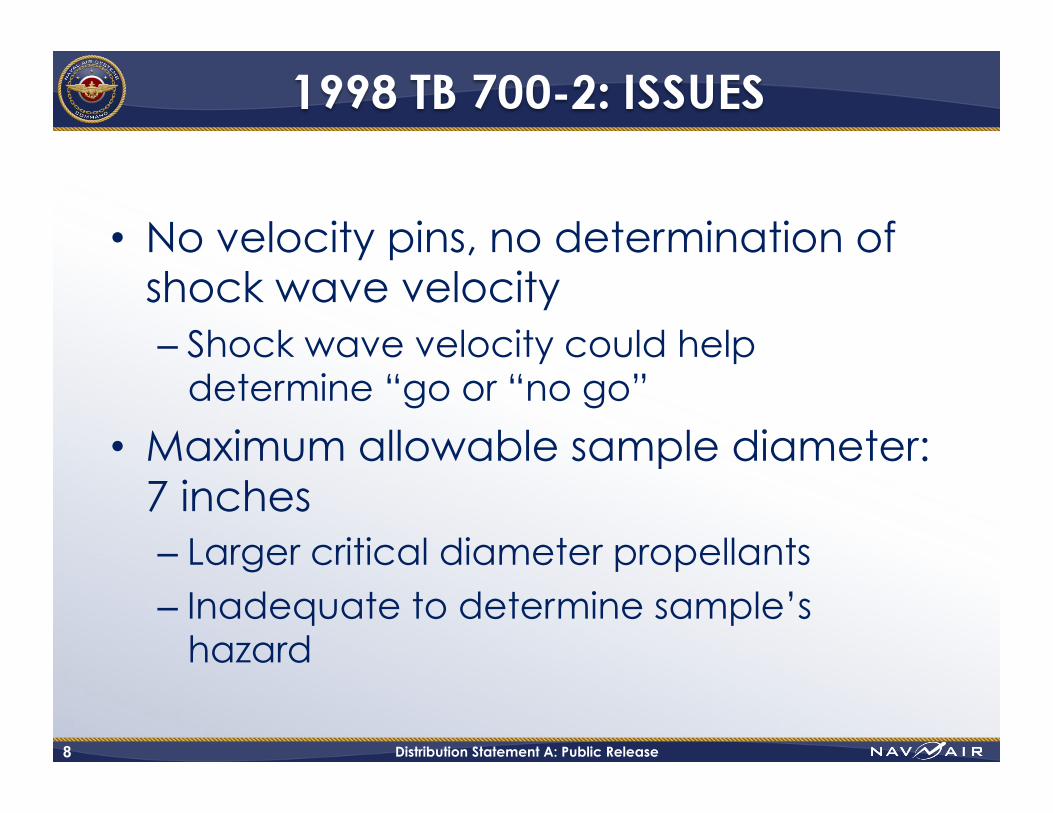
• No velocity pins, no determination of shock wave velocity – Shock wave velocity could help
determine “go or “no go”
• Maximum allowable sample diameter: 7 inches – Larger critical diameter propellants – Inadequate to determine sample’s
hazard
8
Distribution Statement A: Public Release
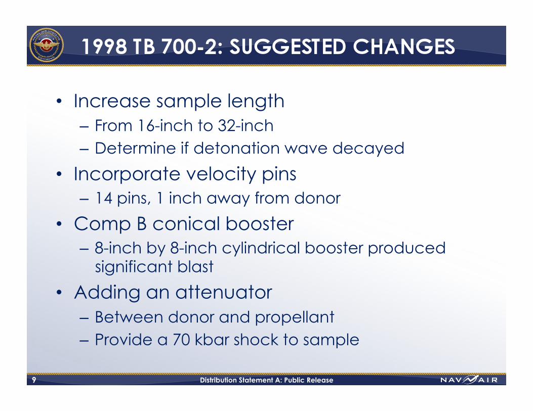
• Increase sample length – From 16-inch to 32-inch – Determine if detonation wave decayed
• Incorporate velocity pins – 14 pins, 1 inch away from donor
• Comp B conical booster – 8-inch by 8-inch cylindrical booster produced
significant blast
• Adding an attenuator – Between donor and propellant – Provide a 70 kbar shock to sample
9
2012: TB 700-2
10
Distribution Statement A: Public Release
• SLSGT suggestions resulted in modifications – DDESB document signed by Capt. William
Wright, Chairman
• Three options replace section 6-6(c) of 1998 TB 700-2 – Option 1. Refined SLSGT – Option 2. Determine unconfined dcrit
– Option 3. Missile motor diameter
11
Distribution Statement A: Public Release
• Refined version of SLSGT
• 32-inch-long sample • 14 velocity pins • Either a right circular
cylinder or conical booster
• No PMMA attenuator
12
Distribution Statement A: Public Release 13
• Determine Critical Diameter [A]
• Address confinement thickness concern – Test in equivalent
confinement to motor case
Distribution Statement A: Public Release 14
• Minimum sample diameter [B] – 5-inches – 150 percent of
unconfined critical diameter
• 14 velocity pins minimum
• Attenuation to allow 70-kbar shock
Distribution Statement A: Public Release
• Similar to Option 2 • Confinement = motor
case • Sample diameter = missile
diameter • Closely recreate original
environment an item would be used in
• More applicable to smaller tactical missiles
• Much less cost effective for larger diameter solid rocket motors
15
Distribution Statement A: Public Release
• Gap research continued • Role of confinement
– Determine effects of different confinement – AP/Al/HTPB propellant 12-inch diameter sample – Different case materials – Different case wall thickness • No confinement • Schedule 40 PVC pipe • Schedule 80 PVC pipe • 0.37-inch aluminum wall thickness • 0.0687-inch aluminum wall thickness • ½-inch thick steel wall thickness
16
Distribution Statement A: Public Release
Lindfors, et al. AP/Al/HTPB Propellant
17
• ½-inch steel case
– Highest confinement
– Highest pressure
• Pressure at 175 µsec = 312.2 kbar • Original shock wave pressure = 280 kbar
Time/ Case (μs)
Unconfined Propellant
(ρ = 1.850)
12.75” x 0.5” Steel Case Rho = 7.90
Schedule 40 PVC
Rho = 1.376
Schedule 80 PVC
Rho = 1.376
12.75” x 0.375”
Aluminum Rho = 2.703
12.75” x 0.687”
Aluminum Rho = 2.703
100 103.2 103.4 98.5 99.4 99.3 100.1 125 111.2 139.4 109.2 109.32 110.3 119.0 150 118.1 186.8 115.0 115.4 124.6 141.3 175 137.4 312.2 133.4 132.4 162.9 194.5
Distribution Statement A: Public Release
• Studies of four different propellants • Modified DYNA-2D predictions vs experimental data
– Zero cards vs 50 cards • HD 1.1 vs HD 1.3
• Reduce size of donor – no apparent effect on walls • Confinement change
– From ½-inch steel walls to PVC • PVC impedance < steel impedance • Rocket motor case confinement
– Reproduce observed gap test results – Model could be a viable tool in designing alternate gap
test configurations
18
Distribution Statement A: Public Release
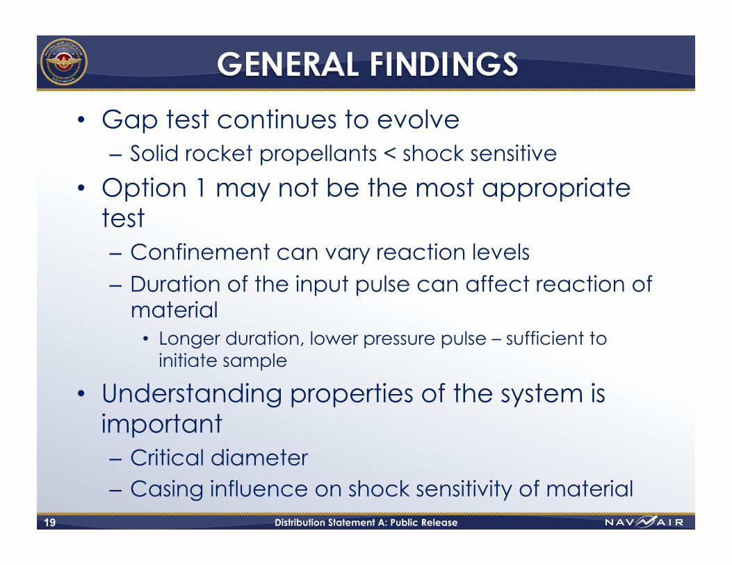
• Gap test continues to evolve – Solid rocket propellants < shock sensitive
• Option 1 may not be the most appropriate test
– Confinement can vary reaction levels
– Duration of the input pulse can affect reaction of material • Longer duration, lower pressure pulse – sufficient to
initiate sample • Understanding properties of the system is
important – Critical diameter – Casing influence on shock sensitivity of material
19
Distribution Statement A: Public Release 20
• Which test to use? – Understand the system
• Some problems are known – Solutions have yet to be found
• Additional work is needed – Experimental and analytical
It is important to consult the Service Hazard Classifier early in the process when
determining which test standard to implement during any program development effort
Distribution Statement A: Public Release
• Extensive literature review – Use and evolution of critical diameter and gap
tests through the years
• Papers are being reviewed and summarized – Hazard Classification – TB 700-2 – Critical diameter – Gap tests – Alternate tests
21
The authors are soliciting papers in these areas to include in the study
Distribution Statement A: Public Release
• Important to understand the different types of gap tests used – Assess shock sensitivity
• More comprehensive understanding of each test configuration – Help identify methods to correlate data between
tests – Identifying origins, test setup, applications, and
limitations • Determine what the results of each test reveal about
the material’s shock sensitivity
22

Distribution Statement A: Public Release
The authors would like to thank: B. E. Knoblett and G. E. Walseman
23

QUESTIONS
24
Distribution Statement A: Public Release
• Paul W. Cooper. Explosives Engineering, 2nd Edition. John Wiley & Sons, 2008. • E. A. Eyster, L. C. Smith, and S. R. Walton. “The Sensitivity of High Explosives to Pure Shocks,”
NOLM 10,336, 14 July 1949. • Jonas A. Zukas and William P Walter. Explosive Effects and Applications, Springer, 1998. • Donna Price. “Gap Tests and How They Grew,” Minutes of the Explosives Safety Seminar
(22nd), Anaheim, California, August 1986, pp. 365-380. (AD-A181 274.) • D. Price, A. R. Clairmont, Jr., and J. O. Erkman. ”The NOL Large Scale Gap Test III.
Compilation of Unclassified Data and Supplementary Information for Interpretation of Results,” Naval Surface Warfare Center, White Oak, Maryland, 8 March 1974. (NOLTR 74-40; publication UNCLASSIFIED.)
• R. B. Elwell, O. R. Irwin, and R. W. Vail, Jr. “Project SOPHY Solid Propellant Hazards Program,” Aerojet-General Corporation, 88 pp, 31 December 1966. (AFRPL-TR-66-276; publication UNCLASSIFIED.)
• Department of Defense (DoD) Ammunition and Explosives Hazard Classification Procedures Joint Technical Bulletin TB 700-2/NAVSEAINST 8020.8B/TO 11A-1-47/DLAR 8220.1, 5 January 1998.
• Current Efforts to Develop Alternate Test Protocols for the Joint Technical Bulletin “Department of Defense Ammunition and Explosives Hazard Classification Procedures,” TB 700-2, dated 5 January 1998.
25
Distribution Statement A: Public Release
• A. J. Lindfors, O. E. R. Heimdahl, T. L. Boggs, and J. J. Davis. “Determination of Shock Sensitivity of Propellants in Gap Test Configuration,” 38th JANNAF CS/APS/PSHS Meeting, Destin, Florida, April 2002.
• P. J. Miller and T. L. Boggs. “Recent Hazard Classification Test Data on SRM Propellants,” 29th DoD Explosives Safety Seminar Proceedings, New Orleans, Louisiana, July 2000.
• J. C. Foster, Jr, K. R. Forbes, M. E. Gunger, and B. G. Craig. “An 8-Inch Diameter, Heavily Confined Card Gap Test,” AFATL/DLJW, Eglin AFB, Florida, November 1985. (AFATL-TR-85-98; publication UNCLASSIFIED.)
• Current Efforts to Develop Alternate Test Protocols for the Joint Technical Bulletin “Department of Defense Ammunition and Explosives Hazard Classification Procedures” TB700-2, dated 5 January 1998. (Also see D. F. Schwartz, R. R. Bennett, K. J. Graham, and T. L. Boggs, 19th JANNAF Propulsion Systems Hazards Subcommittee Meeting, CPIA Publication 704, Vol. 1, pp. 117-131, Monterey, California, November 2000. (2001-0053KA.)
• P. J. Miller, T. L. Boggs, and K. J. Graham. “Reactive Flow Modeling of the SLSGT: Progress Towards Developing a New Shock Sensitivity Test for Hazards,” 19th JANNAF Propulsion Systems Hazards Subcommittee Meeting, CPIA Publication 704, Vol. 1, pp 132-143, Monterey, California, November 2000.
26
Distribution Statement A: Public Release
• Chemical Propulsion Information Agency. Joint JANNAF/DDESB Workshop on Hazards Classification of Large Rocket Motors Workshop Report, Alexandria, Virginia, June 2001.
• William Wright. “Changes to Alternate Test Procedures for Solid Propellant Rocket Motors,” Department of Defense Explosives Safety Board Memorandum DDESB-KT, Alexandria, Virginia, January 2002.
• Department of Defense (DoD) Ammunition and Explosives Hazard Classification Procedures Joint Technical Bulletin TB 700-2. 2012.
• A. J. Lindfors, O. E. R. Heimdahl, T. L. Boggs, and T. AtienzaMoore. “Shock Sensitivity of Propellants Using the Super Large Scale Gap Test,” 31st DoD Explosives Safety Seminar, San Antonio, Texas, August 2004.
• R. R. Bennett, D. F. Schwartz, K. J. Graham, and T. L. Boggs. “Comments and Position Regarding the Joint Technical Bulletin ‘Department of Defense Ammunition and Explosives Hazard Classification Procedures’ TB 700-2, dated 5 January 1998.” 29th U.S. DoD Explosives Safety Seminar, New Orleans, Louisiana, July 2000.
• A. L. Bowman, C. A. Forest, J. D. Kershner, C. L. Mader, and G. H. Pimley. “Numerical Modeling of Shock Sensitivity Experiments,” Proceedings of the Seventh Symposium (International) on Detonation, Annapolis, Maryland, June 1981.
• P. J. Miller and A. J. Lindfors. “Shock Loading and Reactive Flow Studies of Void Induced AP/Al/HTPB Propellants,” in Shock Compression of Condensed Matter, AIP Publication CP429, 1997.
27