Embed Size (px)
Citation preview
© 2
005:
Inst
ituto
de
Ast
rono
mía
, UN
AM
- II
Inte
rna
tiona
l GTC
Wo
rksh
op
: Sc
ienc
e w
ith G
TC 1
st-l
ight
Inst
rum
ent
s a
nd th
e L
MT
Ed. A
. M. H
ida
lgo
-Gá
me
z, J
. J. G
onz
ále
z, J
. M. R
od
rígue
z Es
pin
osa
& S
. To
rre
s-Pe
imb
ert
RevMexAA (Serie de Conferencias), 24, 13–20 (2005)
STATUS AND SCIENTIFIC PERFORMANCE OF ELMER, A
MULTI-PURPOSE INSTRUMENT FOR THE GTC
M. L. Garcıa-Vargas,1 P. L. Hammersley,1 E. Sanchez-Blanco,1 R. Kohley,1 J. M. Martın-Fleitas,1
L. Cavaller-Marques,1 M. Maldonado,1 and R. Vilela1
RESUMEN
Elmer es un instrumento para el GTC disenado para observar en el intervalo espectral entre 365 y 1000nm. Los modos de observacion para Dıa Uno son: Imagen, Espectroscopıa de rendija larga y multi-objeto,Espectroscopıa sin rendija, Fotometrıa rapida y Espectroscopıa rapida con rendija corta; en un campo de 4.2arcmin de diametro. Elmer dispone de resoluciones espectrales de 250, 1000 y 2500, cubriendo todo el intervalode longitud de onda. Elmer ha sido disenado y gestionado en la Oficina de Proyecto de GTC. El instrumento seencuentra en las fases finales de pruebas previas a su envıo al ORM. En esta contribucion se da una descripciongeneral y un resumen de sus prestaciones cientıficas
ABSTRACT
ELMER is an instrument for the GTC designed to observe between 365 and 1000 nm. The observing modes forthe instrument at Day One shall be: Imaging, Long Slit and Mask-Multi-object Spectroscopy, Slit-less multi-object spectroscopy, Fast Photometry and Fast short-slit spectroscopy, over a FOV of 4.2 arcmin diameter.Spectral resolutions of 250, 1000 and 2500, covering the whole spectral range, will be available. ELMER hasbeen designed and managed within the GTC Project Office. ELMER is currently in the final stage of testingprevious to be shipped to the Observatory. The general description of this instrument and its expected scientificperformance are summarised.
Key Words: INSTRUMENTATION: SPECTROSCOPY — INSTRUMENTATION: MISCELLANEOUS
— METHODS: OBSERVATIONAL
1. INTRODUCTION
The GTC Science Committee, SAC, recom-mended the development of an assurance instru-ment to be designed and kept under the control ofthe GTC Project Office, hereafter PO, in order toguarantee scientific operations on Day One. Somemonths later, in October 2000, ELMER, an imagerand low-resolution spectrograph in the visible wave-length range (365 nm - 1000 nm), was approved tobe put in operation in case of delays in the arrivalof the instruments developed by external researchinstitutions. ELMER design was driven by a basicset of scientific requirements, together with the strictboundary conditions both physical, moderate massand size to fit at Folded-Cassegrain, and manage-rial, to have a “low” risk instrument, with a reason-able price and at a guaranteed delivery date. Thedesign approach pursued proven technical solutions.The drawbacks have been converted into advantages.The low budget and the Folded-Cassegrain installa-tion implied a small FOV and consequently relativelysmall optics, which allowed an optimized optical de-
1GTC Project, Instituto de Astrofısica de Canarias, LaLaguna, Spain.
sign with high throughput, which makes ELMER avery sensitive instrument. The oversized detectorhas been used to implement many fast, fashionableand time-resolved modes, unique in the large teles-cope world. Its simplicity will lead to very efficientoperation and maintenance. ELMER is a fact, show-ing an excellent performance in the laboratory at LaLaguna (Tenerife), where it is in the last phase oftesting, previous to go to the Observatorio del Roquede los Muchachos, ORM, where the GTC telescope isbeing integrated. ELMER has been developed overa global schedule of 4 years, with a cost of 1.23 M
�
plus an additional effort of 12 man-year of the GTCPO engineers.
ELMER offers Imaging and Spectroscopy over aFOV of 4.2 arcmin diameter. Imaging is done witha set of broad band and narrow band filters. Spec-troscopy is possible through long slits of differentwidths, masks for multi-object and also in a slit-less mode. ELMER offers three different spectralresolutions with resolving powers of R = 250, 1000and 2500, for the spectroscopy modes and over thewhole wavelength range. These resolutions are pos-sible thanks to the use of optimized pupil elements
13

© 2
005:
Inst
ituto
de
Ast
rono
mía
, UN
AM
- II
Inte
rna
tiona
l GTC
Wo
rksh
op
: Sc
ienc
e w
ith G
TC 1
st-l
ight
Inst
rum
ent
s a
nd th
e L
MT
Ed. A
. M. H
ida
lgo
-Gá
me
z, J
. J. G
onz
ále
z, J
. M. R
od
rígue
z Es
pin
osa
& S
. To
rre
s-Pe
imb
ert
14 GARCIA-VARGAS ET AL.
TABLE 1
ELMER GENERAL CAPABILITIES
General Capabilities
Focal Station Nasmyth B and Folded-Cassegrain
Wavelength range 0.365 1.000 µm
FOV 3.0 arcmin x 3.0 arcmin
(4.2 arcmin diameter)
Scale at detector 0.195 arcsec/pixel
Detector Focal Plane 2048 x 4096 Marconi CCD44-82
Pixel Size 15µm x 15µm
Detector capabilities Charge shuffling and Frame transfer
Imaging Modes
Broad band Filters SDSS set: g’, r’, i’, Z’
Narrow band Filters [SII]wide 6726, [SII]narrow 6719
Hα wide 6568, Hα narrow 6567
[OI]6305, [OIII]4985
Hβ 4863, [OII]3728
Neutral density filters ND2 and ND3
Direct Imaging Over 4.2arcmin φ FOV
Fast Photometry Mode Aperture: 3 arcmin x 12.48 arcsec
Duty cycle > 98% at 1 Hz
Charge Shuffling yes (at 50µs/line)
Spectroscopy Modes
Spectral resolution R = 50-500 (2 prisms)
R = 1000 (2 grisms)
R = 2500 (6 VPHs)
Dispersive elements 2 prisms , 2 grisms and 6 VPHs
Long Slit 3’ x 0.6”, 1.2”, 2.0” and 5.0”
Fast short slit 20” x 0.6”, 1.2”, 2.0” and 5.0”
Charge shuffling 3’ x 0.6”, 1.2”, 2.0” and 5.0”
Mask multi-object 3’ x 3’ FOV
Positions for masks Up to 4 depending on configuration
for each of them: prisms, grisms and VPHs (VolumePhase Holographic gratings) respectively. Finally,ELMER fast modes (Fast Photometry, Fast SlitSpectroscopy, and Charge Shuffling Spectroscopy)are possible thanks to the frame transfer (ability ofexposing the upper half of the detector while read-ing the lower half) and charge shuffling (at a rateof 50µs/line on the readout direction) capabilities ofthe detector and the controller. ELMER capabili-ties are summarized in Table 1. This contributionincludes both, the general description of the instru-ment, presented in an oral contribution, and the sci-entific performance, presented in two posters at thetime of the conference.
2. TECHNICAL DESCRIPTION
Elmer is divided into the main core (commonfor Folded-Cassegrain and Nasmyth), the Nasmythadapter, to attach the core to the telescope rota-
tor flange and two cabinets, to host the electronicequipment. These cabinets will be supported onthe Nasmyth attachment flange and therefore rotateswith the instrument, when it runs at Nasmyth whilethey will be fixed on the telescope elevation ringwhen it operates at Folded-Cassegrain. ELMER coreis functionally separated into several subsystems:Support Structure, Slit Unit, Field Lens, Collima-tor, two Folder Mirrors, Shutter, two Pupil Wheels,(for filter and for prism/grism/VPH respectively),the Camera, the Cryostat and the Control System.An overall description is given in Sanchez-Blanco &Garcıa-Vargas (2004). Figure 1 shows a general viewof ELMER main core as-built.
2.1. Main Optics
ELMER optical system consists on a field lens, acollimator, and a camera, plus two folder mirrorsto package the instrument into the small Folded-Cassegrain envelope. Light passes through the slitor the open position at the telescope focal plane, thefield lens, a folder mirror, the collimator and the se-cond folder mirror. Then, it passes through the shut-ter aperture and the two pupil wheels (filter wheeland prism/grism/VPH wheel). Finally, a 4-elementcamera (two doublets and two single lens) producesthe image on the detector. The whole optical designhas been done at the PO.
Only two materials for lens blanks (S-LAL18from OHARA and CaF2 from Schott Lithotec AG)were used in Elmer main optics in order to op-timize the coatings. All the blanks were orderedimmediately after the Preliminary Design Review,PDR, characterized at the PO, see Sanchez-Blanco,Garcıa-Vargas & Maldonado (2002), and sent to thepolisher, SESO. In addition an extra Field lens inFused Silica was polished by INAOE in order to mit-igate the risk of a breakage of the large CaF2 fieldlens, as recommended by the PDR panel. Opticshas been exhaustively tested at both, the factory(SESO) and the PO laboratory, showing excellentperformance in terms of image quality and through-put as described in Sanchez-Blanco & Garcıa-Vargas(2004).
Regarding the folder mirrors, the blanks (in Ze-rodur) were ordered from Schott Glass and polish-ing/coating was awarded to INAOE. A special blue-reflectance protected silver coating was used.
2.2. Filters
Four SDSS broad band, 8 narrow band and 2 neu-tral density for Imaging and 2 order sorting filtersfor spectroscopy were ordered from OMEGA Opti-cal, where they were characterized in pass-band and

© 2
005:
Inst
ituto
de
Ast
rono
mía
, UN
AM
- II
Inte
rna
tiona
l GTC
Wo
rksh
op
: Sc
ienc
e w
ith G
TC 1
st-l
ight
Inst
rum
ent
s a
nd th
e L
MT
Ed. A
. M. H
ida
lgo
-Gá
me
z, J
. J. G
onz
ále
z, J
. M. R
od
rígue
z Es
pin
osa
& S
. To
rre
s-Pe
imb
ert
ELMER STATUS AND PERFORMANCE 15
Fig. 1. ELMER main structure and mechanisms, as-built, in the special container in which it was transported from thefactory to the GTC PO at La Laguna.
transmission. Filters have already been assembledon their mounts. The transmitted wavefront imagequality has been measured at PO.
TABLE 2
BROAD BAND FILTER SET
Filter-ID Central λ Cut-on(1%) Cut-off(1%) % Transmission
± 10 A ± 10 A ± 10 A @ λPeak
SDSS-g’ 4830 A 4070 A 5570 A 89.07 @ 5190 A
SDSS-r’ 6170 A 5350 A 6980 A 92.69 @ 6060 A
SDSS-I’ 7720 A 6800 A 8630 A 98.54 @ 8020 A
SDSS-z’ 8990 A 8130 A 9850 A 94.35 @ 9480 A
2.3. Pupil elements for spectroscopy
The final grid of pupil elements for spectroscopyis composed by 2 prisms, 2 grisms and 6 VPHs, cov-ering the whole wavelength range with three differ-ent resolutions R=250, 1000 and 2500 respectively.Spectral resolutions are given for the nominal slit
TABLE 3
NARROW BAND FILTER SET
Filter-ID λc (A) FWHM % Trans Comments
±10 A @Peak
[OII] 3727 A rejected
Hβ 4858 A 27 A 73.0 % Hβ4861A
[OIII] 4976 A 57 A 86.9 % [OIII]4959+5007A
[OI] 6289 A 44 A 87.5 % [OI]6300A
Hα broad 6558 A 70 A 81.1 % Hα6563A+[NII]6548A
Hα narrow 6562 A 16 A 77.3 % Hα6563A
[NII] 6584 Arejected
[SII] narrow 6718 A 17 A 87.0 % [SII]6717A
[SII] broad 6711 A 70 A 90.1 % [SII]6717+6731A
width (0.6”). All the values are given for a cen-tral slit. Table 4 summarises the available elements.Prism, Grism and VPH detailed design was done atthe PO. The design was constrained by the budgetthat led to the need of a strong optimization of the

© 2
005:
Inst
ituto
de
Ast
rono
mía
, UN
AM
- II
Inte
rna
tiona
l GTC
Wo
rksh
op
: Sc
ienc
e w
ith G
TC 1
st-l
ight
Inst
rum
ent
s a
nd th
e L
MT
Ed. A
. M. H
ida
lgo
-Gá
me
z, J
. J. G
onz
ále
z, J
. M. R
od
rígue
z Es
pin
osa
& S
. To
rre
s-Pe
imb
ert
16 GARCIA-VARGAS ET AL.
materials, the number and size of the blanks and thecut angles in order to minimize the cost. The ex-pected scientific performance is summarized in Sec-tion 3.3.
TABLE 4
PUPIL ELEMENTS FOR SPECTROSCOPY
Element-ID λ coverage (A) λc (A) R(@λc) Type
PR430-0190 3650 - 6950 4350 145 Prism
PR800-0160 6509 - 9500 8000 127 Prism
GR520-1000 3650 - 6700 5175 962 Grism
GR790-1000 5800 - 10000 7900 957 Grism
VP410-2500 3650 - 4500 4100 2463 VPH
VP480-2400 4250 - 5450 4850 2350 VPH
VP610-2300 5350 - 6850 6100 2255 VPH
VP660-2500 5800 - 7300 6550 2510 VPH
VP730-2500 6500 - 8200 7350 2481 VPH
VP880-2500 7800 - 9900 8850 2448 VPH
Prisms: We have two dispersive prisms (red andblue) for low resolution (R from 500 to 50) with a flattransmission over 90% within the whole range. Theerror budget available was split between the blanksand surface quality, balancing the cost versus per-formance. Ghost analysis was also done. Detailedopto-mechanical mounting was done in terms of po-sitioning/tilts, thermal/mounting stress and gravita-tional strain. Three individual prisms compose eachprism unit. Blanks were ordered from OHARA, cha-racterized at PO and sent to INAOE for polishing,with the exception of the ZnSe prism (for the red-prism unit) that was ordered (blank, polishing andcoating) from Janos. The process of gluing and as-sembling the prisms on their mounts to produce thefinal unit has been done at the PO, as detailed inSanchez-Blanco & Garcıa-Vargas (2004).
Grisms: Two low-resolution standard grismswere designed to cover the whole spectral rangewith R=1000: one for the blue, the other one red-optimized. Blanks were ordered from OHARA. Thepolishing/coating of the prisms and the flat windowswas awarded to INAOE. Gratings were ordered fromRichardson (Thermo RGL) who replicated standardgratings on the polished windows. After testing theelements separately, the Elmer team at the PO hasglued the windows to the gratings on their corre-
sponding prisms and has assembled the units in themounts.
VPHs: A set of 6 VPHs has been designed tocover the whole spectral range with a resolution ofabout 2500. A VPH grating sandwiched between twoprisms composes each unit. Blanks for both, win-dows and prisms, were ordered from OHARA, cha-racterized at the PO and sent to SESO for polishingand coating. Holograms were awarded to WasatchPhotonics who will finish the elements in October04.The final assembly will be done at the PO.
2.4. Structure and Mechanisms
A call for tender for the Detailed Design, Manu-facturing, Integration and Tests of the Elmer Struc-ture and Mechanisms was launched in July 2001.This work package was awarded to the Spanish jointventure MEDIA-SPASA, M-S. Details of the designcan be seen in Ronquillo, Vega, & Cavaller-Marques(2002). The PO and M-S have been working in aframework of a successful collaboration. The mecha-nism functionality and performance, the dimensionalverification, the maintenance and accessibility proce-dures and the flexure determinations were the maintopics of the testing program at factory (see Maldo-nado et al. and Martın-Fleitas et al., this confer-ence). The tests were done in presence and with thecollaboration of the PO Elmer team, who has beenworking hand by hand with the contractor to opti-mize the system. Ronquillo et al. (2004) describesthe whole testing process at factory. The structurewas delivered in October03 at La Laguna. It hasbeen installed within a portable clean room in theIAC Workshop, where the PO team is finishing theintegration and testing previous to ship the instru-ment to the GTC facilities at the ORM. The struc-ture and mounts of the folder mirrors were manu-factured by LIDAX (Madrid) and the mirrors havealready been integrated on their mounts.
2.5. Shutter
It has been manufactured by the AstronomicalInstitutes of the University of Bonn (AIUB). Theshutter working principle is based on a bi-directionalslit-type shutter with two independent blades (aper-ture size 150mm x 150mm) driven by stepper motors.This shutter allows effective single exposure times aslow as 10 ms with an time error for consecutive expo-sures less than 400ms and exposure inhomogeneityless than 1ms over full FOV. The maximum repeti-tion rate is 2.5Hz.
2.6. Detection System
It is composed by the CCD Head (designed bythe PO and manufactured at the IAC workshop) and

© 2
005:
Inst
ituto
de
Ast
rono
mía
, UN
AM
- II
Inte
rna
tiona
l GTC
Wo
rksh
op
: Sc
ienc
e w
ith G
TC 1
st-l
ight
Inst
rum
ent
s a
nd th
e L
MT
Ed. A
. M. H
ida
lgo
-Gá
me
z, J
. J. G
onz
ále
z, J
. M. R
od
rígue
z Es
pin
osa
& S
. To
rre
s-Pe
imb
ert
ELMER STATUS AND PERFORMANCE 17
Fig. 2. ELMER Structure and Mechanisms as installedat the IAC Workshop, where the PO team is finishingthe integration
a commercial LN2 Dewar Back (from SNLS). Thecomplete description of the Elmer Detection Systemand the associated testing campaign done at the POlaboratory is given in Kohley et al. (2004) and Koh-ley et al. (this conference).
2.7. Elmer Control System, ELCS
The ELCS comprises the hardware and softwareof the instrument. The ELCS software is fully in-tegrated with the rest of the GTC Control System.The main packages of the ELCS are (a) the IMCS,Instrument Mechanism Control System, to controland to monitor all the ELMER mechanisms and sen-sors (b) the IDAS, Instrument Data Acquisition Sys-tem, which interfaces the detector controller, receiv-ing the raw scientific data from the CCD controller;(c) the Login and Alarm services; (d) a completeUser Interface; (e) the Sequencer, to operate the ins-trument in coordination with the rest of subsystemsof the GTC; (f) the Observing Tool, to allow theusers to prepare and submit their observation pro-posals and (g) a complete ELMER Data Pipelinewith the corresponding reduction templates for allthe observing modes. The ELCS hardware is com-posed of two Local Control Units (LCU) one forData Acquisition (IDAS) and another one for Me-chanisms Control (IMCS). Each LCU comprises aMotorola MVME2432 CPU card (running VxWorks)and Ethernet, CANopen and Gigabit communica-tion modules, mounted on a single VME crate witha divided back-plane. These CPUs are responsiblefor executing the ELCS software, which controls me-chanisms and data acquisition.
3. SCIENTIFIC PERFORMANCE
3.1. Transmission
Elmer high throughput is one of the main mustsof the instrument. A specific coating demonstra-tion program was done with SESO in order tooptimise the coatings for the Elmer lenses mate-rials (CaF2 and S-LAL18), as described in Sanchez-Blanco & Garcıa-Vargas (2004) and Sanchez-Blanco& Garcıa-Vargas (2002).
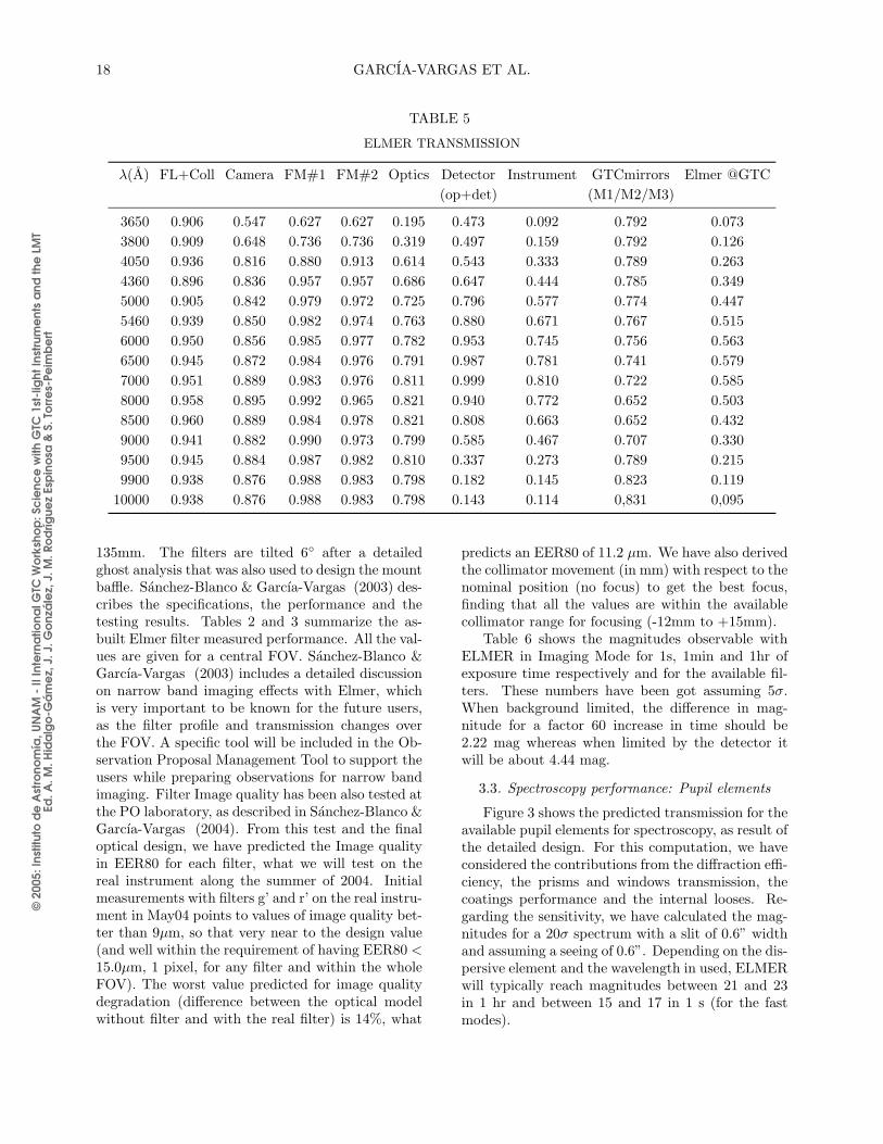
Protected doped Ag coatings were selected forthe folder mirrors, which were coated by INAOE.Table 5 shows the estimated Elmer throughput. Col-umn 1 gives the wavelength in A. Regarding theOptics, data correspond to real transmission mea-surements of the different contributors in a centralaperture (except for 365nm and 388nm points forwhich data come from the manufacturer. Columns2 to 5 give measured values at the PO laboratoryin a central field. In particular, column 2 gives thetransmission of the Field lens plus the Collimator,which were measured together; Column 3 gives Ca-mera transmission; Column 4 and 5 gives the re-flectance of Folder mirror #1 and #2 respectively.Column 6 gives the Optics transmission (product ofcolumns 2 to 5). Column 7 is the CCD44-82 detectorQuantum Efficiency (QE) measured by Marconi, asin the delivered data-sheet. The final detector char-acterisation will be done along the summer of 2004.Final figures will be given after the testing and char-acterisation period. Column 8 is the total Elmerthroughput (except for the pupil elements). Column9 gives the estimated transmission of the GTC af-ter the 3 Al mirrors (valid for operation at both,Nasmyth and Folded-Cassegrain). The data for theGTC mirrors reflectance is based on standard Alu-minium coating samples. Unfortunately, the GTCwill not have UV enhanced protected silver coatingson its mirrors at Day One, what will affect significa-tively the final throughput. Finally, column 10 showsthe predicted Elmer throughput when operating atthe GTC.
3.2. Imaging performance: Filter sensitivities
The instrument pupil is located 50mm in frontof the camera. All fields in Elmer FOV are withina pupil of 89.2mm at this position (87 mm is thefootprint of each individual field). Nevertheless, thefilters are located in the first wheel, which is about200mm away from this position. So the filter is beencrossed at slightly different positions for each field.Due to this reason and to allow secondary move-ments and alignment, the filters were specified to aclear aperture over 126mm and a physical size of
© 2
005:
Inst
ituto
de
Ast
rono
mía
, UN
AM
- II
Inte
rna
tiona
l GTC
Wo
rksh
op
: Sc
ienc
e w
ith G
TC 1
st-l
ight
Inst
rum
ent
s a
nd th
e L
MT
Ed. A
. M. H
ida
lgo
-Gá
me
z, J
. J. G
onz
ále
z, J
. M. R
od
rígue
z Es
pin
osa
& S
. To
rre
s-Pe
imb
ert
18 GARCIA-VARGAS ET AL.
TABLE 5
ELMER TRANSMISSION
λ(A) FL+Coll Camera FM#1 FM#2 Optics Detector Instrument GTCmirrors Elmer @GTC
(op+det) (M1/M2/M3)
3650 0.906 0.547 0.627 0.627 0.195 0.473 0.092 0.792 0.073
3800 0.909 0.648 0.736 0.736 0.319 0.497 0.159 0.792 0.126
4050 0.936 0.816 0.880 0.913 0.614 0.543 0.333 0.789 0.263
4360 0.896 0.836 0.957 0.957 0.686 0.647 0.444 0.785 0.349
5000 0.905 0.842 0.979 0.972 0.725 0.796 0.577 0.774 0.447
5460 0.939 0.850 0.982 0.974 0.763 0.880 0.671 0.767 0.515
6000 0.950 0.856 0.985 0.977 0.782 0.953 0.745 0.756 0.563
6500 0.945 0.872 0.984 0.976 0.791 0.987 0.781 0.741 0.579
7000 0.951 0.889 0.983 0.976 0.811 0.999 0.810 0.722 0.585
8000 0.958 0.895 0.992 0.965 0.821 0.940 0.772 0.652 0.503
8500 0.960 0.889 0.984 0.978 0.821 0.808 0.663 0.652 0.432
9000 0.941 0.882 0.990 0.973 0.799 0.585 0.467 0.707 0.330
9500 0.945 0.884 0.987 0.982 0.810 0.337 0.273 0.789 0.215
9900 0.938 0.876 0.988 0.983 0.798 0.182 0.145 0.823 0.119
10000 0.938 0.876 0.988 0.983 0.798 0.143 0.114 0,831 0,095
135mm. The filters are tilted 6◦ after a detailedghost analysis that was also used to design the mountbaffle. Sanchez-Blanco & Garcıa-Vargas (2003) des-cribes the specifications, the performance and thetesting results. Tables 2 and 3 summarize the as-built Elmer filter measured performance. All the val-ues are given for a central FOV. Sanchez-Blanco &Garcıa-Vargas (2003) includes a detailed discussionon narrow band imaging effects with Elmer, whichis very important to be known for the future users,as the filter profile and transmission changes overthe FOV. A specific tool will be included in the Ob-servation Proposal Management Tool to support theusers while preparing observations for narrow bandimaging. Filter Image quality has been also tested atthe PO laboratory, as described in Sanchez-Blanco &Garcıa-Vargas (2004). From this test and the finaloptical design, we have predicted the Image qualityin EER80 for each filter, what we will test on thereal instrument along the summer of 2004. Initialmeasurements with filters g’ and r’ on the real instru-ment in May04 points to values of image quality bet-ter than 9µm, so that very near to the design value(and well within the requirement of having EER80 <
15.0µm, 1 pixel, for any filter and within the wholeFOV). The worst value predicted for image qualitydegradation (difference between the optical modelwithout filter and with the real filter) is 14%, what
predicts an EER80 of 11.2 µm. We have also derivedthe collimator movement (in mm) with respect to thenominal position (no focus) to get the best focus,finding that all the values are within the availablecollimator range for focusing (-12mm to +15mm).
Table 6 shows the magnitudes observable withELMER in Imaging Mode for 1s, 1min and 1hr ofexposure time respectively and for the available fil-ters. These numbers have been got assuming 5σ.When background limited, the difference in mag-nitude for a factor 60 increase in time should be2.22 mag whereas when limited by the detector itwill be about 4.44 mag.
3.3. Spectroscopy performance: Pupil elements
Figure 3 shows the predicted transmission for theavailable pupil elements for spectroscopy, as result ofthe detailed design. For this computation, we haveconsidered the contributions from the diffraction effi-ciency, the prisms and windows transmission, thecoatings performance and the internal looses. Re-garding the sensitivity, we have calculated the mag-nitudes for a 20σ spectrum with a slit of 0.6” widthand assuming a seeing of 0.6”. Depending on the dis-persive element and the wavelength in used, ELMERwill typically reach magnitudes between 21 and 23in 1 hr and between 15 and 17 in 1 s (for the fastmodes).

© 2
005:
Inst
ituto
de
Ast
rono
mía
, UN
AM
- II
Inte
rna
tiona
l GTC
Wo
rksh
op
: Sc
ienc
e w
ith G
TC 1
st-l
ight
Inst
rum
ent
s a
nd th
e L
MT
Ed. A
. M. H
ida
lgo
-Gá
me
z, J
. J. G
onz
ále
z, J
. M. R
od
rígue
z Es
pin
osa
& S
. To
rre
s-Pe
imb
ert
ELMER STATUS AND PERFORMANCE 19
TABLE 6
MAGNITUDES WITH ELMER IN IMAGINGMODE
Filter-ID t=1s t=60s t=3600s
SDSS-g’ 23.08 25.87 28.11
SDSS-r’ 22.81 25.28 27.50
SDSS-I’ 22.05 24.39 26.61
SDSS-z’ 21.08 23.42 25.65
[OII] 16.57 20.99 24.63
Hβ 18.75 22.94 25.67
[OIII] 20.13 24.06 26.53
[OI] 19.56 22.77 25.05
Hα broad 19.85 23.41 25.74
Hα narrow 18.12 22.19 24.77
[SII] narrow 18.47 22.61 25.21
[SII] broad 20.10 23.73 26.08
3.4. Scientific return: Data Pipeline
Data Reduction Pipelines (DRP) are an essen-tial tool for a quick scientific return. Real timeand off-line pipeline will be fully integrated in theGTC Control System. The data shall be reducedand distributed to the astronomers and the process-ing shall be as complete as possible in order to easea quick scientific return. The data that will go tothe astronomer shall be composed by: (a) the rawdata, both the calibration and the observation files;(b) the scientific validated data (reduced accordingto a standard reduction template) and (c) the non-scientific validated data (reduced also according toa standard reduction but with a higher uncertaintyin the result, since it could be more user or programdependent, such as flux calibration). Also, the as-tronomer will be given the error frames associatedto the reduction process and a quality control re-port done by the GTC staff. The PO Control Groupis developing the complete ELMER DRP (Gomez-Alvarez & Garcıa-Dabo, this conference). The soft-ware architecture, the basic libraries and most of re-duction templates for the main observing modes arealready finished. A complete pipeline optimizationas well as a calibration plan will be produced alongthis year.
4. MANAGEMENT AND PROJECT STATUS
The global ELMER Management strat-egy is widely discussed in Garcıa-Vargas et al.(2002). Elmer budget current estimation (at 95%
Fig. 3. Predicted transmission of Elmer spectroscopyelements according to the detailed design
spent) is 1,23M�
in money. This budget includeseverything (components, external contracts...) ex-cept the detector, which is one of the spares orderedat the time of the purchase order of CCD44-82devices from Marconi. In addition, the PO team hasspent a total of 12 man-years in ELMER and a totalof around 14 man-years is expected until the endof the project. The figures for the manpower comefrom real time reporting sheets. This computationexcludes the ELCS, managed by the GTC ControlGroup. ELMER is also on time. Both, the POand the sub-contractors made their best to meetthe schedule. The global delay has been of 1 yearover the initial plan, what we consider a successsince ELMER has been done with low priority andin parallel with the other tasks within the GTCproject. ELMER is currently installed in a portableclean room inside the IAC Mechanical Workshopat La Laguna (Tenerife), where the Optics werefully integrated at the end of May04. First light ofthe whole system on the final detector is plannedby the end of September04. The tests of the finalperformance will be done along the next months,together with the integration of the ELCS. Thecalibration and maintenance procedures are alsoin progress and are being tested in collaborationwith the maintenance and operations team, tomake easier the hand-over of the instrument to theObservatory. ELMER will be shipped as soon asthe telescope will be ready.
5. CONCLUSIONS
The GTC PO has developed ELMER, an efficientimager and low-resolution spectrograph ready for an

© 2
005:
Inst
ituto
de
Ast
rono
mía
, UN
AM
- II
Inte
rna
tiona
l GTC
Wo
rksh
op
: Sc
ienc
e w
ith G
TC 1
st-l
ight
Inst
rum
ent
s a
nd th
e L
MT
Ed. A
. M. H
ida
lgo
-Gá
me
z, J
. J. G
onz
ále
z, J
. M. R
od
rígue
z Es
pin
osa
& S
. To
rre
s-Pe
imb
ert
20 GARCIA-VARGAS ET AL.
early scientific exploitation of the GTC. ELMER willcarry out broad band and narrow band Imaging andSpectroscopy over a FOV of 4.2 arcmin diameter andspectral resolutions of 250, 1000 and 2500 thanks tothe use of optimized pupil elements. Standard 1-hour exposures will allow detecting, with a high S/N,sources as weak as mag=28 in broad band imaging(5σ) and mag=23 in spectroscopy 20σ for a 0.6” slitand seeing optimized). Fast modes will allow timeresolving programs of very faint targets. As an ex-ample, photometry sampled at 1s exposures will bepossible for sources as faint as mv=23 with 5σ. Fastspectroscopy with S/N=20 will be possible at 1s fortargets of mv=15-17. Although shutter exposuresare limited by the blades movement (time resolutionis of the order of 400ms) the charge shuffling capa-bility allows the movement of a row on the detec-tor in just 50 µs, increasing the time resolution forshutter-less exposures. In addition, the data reduc-tion pipelines will provide a lot of scientific data fora quick scientific return for the GTC users. The POhas done the whole preliminary design, a great partof the detailed design and the management of theproject, in order to minimize the risk, the cost andthe delays. ELMER has consumed 1.23 M
�plus 12
man-years of the PO distributed over 4 years sincethe formal approval of the project in October 2000.ELMER is currently being integrated and characteri-zed at La Laguna in order to shorten the integrationand commissioning time at site. ELMER shall beshipped to the ORM as soon as the telescope will beready.
This project has been possible thanks to thesupport from the GTC Project Scientist, J. M.Rodrıguez-Espinosa. The Elmer team at the POis grateful to the GTC SAC and to the people in-volved in the ELMER project in the different com-panies, whose collaborative spirit with the PO andtheir professional work is contributing every day tothe success of Elmer project. In particular Dr. DenisFappani and Cyril Bourgenot (SESO), Bernardo
Marıa Luisa Garcıa-Vargas, P. L. Hammersley, Ralf Kohley, J. M. Martın-Fleitas, Lluis Cavaller-Marques,Manuel Maldonado, Rafael Vilela and Ernesto Sanchez-Blanco: GTC Project, Instituto de Astrofısica deCanarias, Vıa Lactea s/n, 38200 La Laguna, Spain ([email protected]).
Ronquillo, Mikel Ona, Ester Porras and Miguel An-gel Vega (MEDIA-SPASA), Dr. Francisco Renero(INAOE), Carlos Laviada (LIDAX), Dr. Klaus Reif(Univ. Bonn), Dr. Paul Jorden (Marconi), Dr. JuanCalvo and the workshops personnel (IAC), Dr. Fran-cis Beigbeder (LAOMP), Calvin Grady (OMEGA),the people in their companies and many others whosework contributes to make Elmer a fact.
Marisa Garcıa Vargas personally and speciallythanks the advice and support received at the criticalmoments from Dr. Jerry Nelson, Dr. Harland Epps,Dr. Gerardo Avila, Dr. Bruce Bigelow, Dr. DaveCowley, Dr. Andrew Sheinis and Dr. Guy Monnet.Marisa also wants to express that Elmer is real dueto the continuous effort, professional ability, and un-believable dedication of every member of the Elmerteam.
REFERENCES
Garcıa-Vargas, M. L., Sanchez-Blanco, E., Cavaller, L.
et al. 2002, Proc. SPIE, 4841, 1715
Garcıa-Vargas, M. L., Hammersley, P., Sanchez-Blanco,
E., Kohley, R., Martın-Fleitas, J., Cavaller-Marques,
L., Maldonado M., & Vilela, R. 2004, Proc. SPIE
5492-23
Information at http://www.gtc.iac.es, where all the do-
cuments and drawings are available under request
Kohley, R., Martın, J. M., Cavaller, L., Hammersley, P.,
Suarez, M., Vilela, R., & Beigbeder, F. 2004, Proc.
SPIE, 5492-158
Ronquillo, B., Vega, M. A., & Cavaller-Marques, L. 2002,
Proc. SPIE, 4841, 162
Ronquillo, B., Vega, M. A., Ona, M. et al. 2004, Proc.
SPIE, 5492-137
Sanchez-Blanco, E., & Garcıa-Vargas, M. L. 2002, Proc.
SPIE, 4411, 29
Sanchez-Blanco, E., & Garcıa-Vargas, M. L. 2003, GTC
documents NTE/INST/0213-R, NTE/INST/0214-R,
NTE/INST/0225-R
Sanchez-Blanco, E., & Garcıa-Vargas, M. L. 2004, Proc.
SPIE, 5492-140
Sanchez-Blanco, E., Garcıa-Vargas, M. L., & Maldonado,
M. 2002, Proc. SPIE, 4841, 1241


![[Ioannis Votsis] the Epistemological Status of Scientific Theories](https://img.pdfslide.us/doc/110x75/55cf944f550346f57ba120ee/ioannis-votsis-the-epistemological-status-of-scientific-theories.jpg)