Embed Size (px)
Citation preview
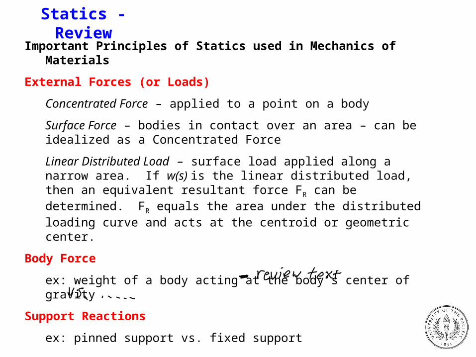
Statics - ReviewImportant Principles of Statics used in Mechanics of Materials
External Forces (or Loads)
Concentrated Force – applied to a point on a body
Surface Force – bodies in contact over an area – can be idealized as a Concentrated Force
Linear Distributed Load – surface load applied along a narrow area. If w(s) is the linear distributed load, then an equivalent resultant force FR can be determined. FR equals the area under the distributed loading curve and acts at the centroid or geometric center.
Body Force
ex: weight of a body acting at the body’s center of gravity
Support Reactions
ex: pinned support vs. fixed support

Equations of Equilibrium
Balance of forces and moments – three dimensions
Balance of forces and moments – coplanar case
Draw Free-Body Diagrams (F.B.D.’s) to help determine forces & moments!
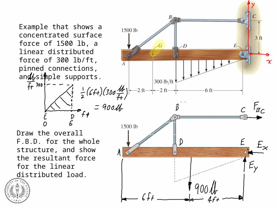
Example that shows a concentrated surface force of 1500 lb, a linear distributed force of 300 lb/ft, pinned connections, and simple supports.
Draw the overall F.B.D. for the whole structure, and show the resultant force for the linear distributed load.
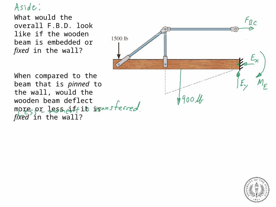
What would the overall F.B.D. look like if the wooden beam is embedded or fixed in the wall?
When compared to the beam that is pinned to the wall, would the wooden beam deflect more or less if it is fixed in the wall?
Internal Resultant Forces
Need to find resultant forces and moments acting within a body, which are necessary to hold the body together when it is subjected to external forces.
Four types of resultant forces:
Normal Force, N – acts perpendicular to a section through the body, and tends to push or pull on the body;
Shear Force, V – acts in the plane of the section, and tends to cause segments of the body to try to slide over one another;
Bending Moment, B – caused by external forces that tend to bend a body about an axis lying with the plane of the section;
Torsional Moment or Torque, T – effect developed when external forces tend to twist one body segment with respect to another.
Use the method of sections to determine the internal resultant forces and moments acting within a body.
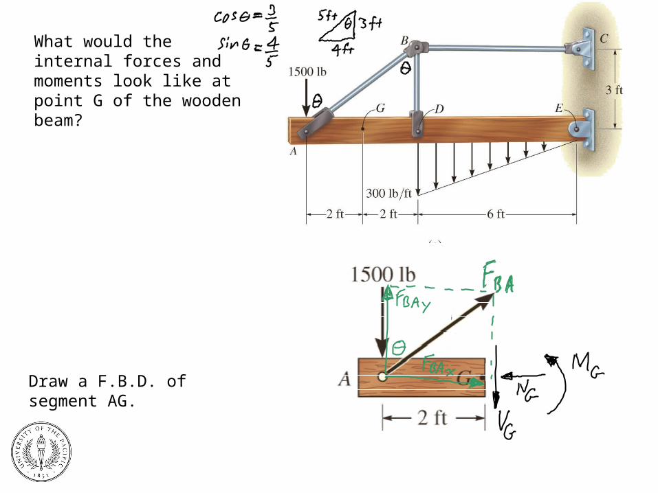
What would the internal forces and moments look like at point G of the wooden beam?
Draw a F.B.D. of segment AG.

(1) Basic Definitions(2) Force(3) Resolution of a Force (3-D)(4) Resultant(5) Moments(6) Equivalent Systems of Forces (Rigid
Bodies)(7) Particle Equilibrium(8) Equilibrium of a Rigid Body
Basic EquationsFree-Body-DiagramsSupports and Corresponding ReactionsRigid Bodies Subjected to Concurrent ForcesDeterminacyTwo and Three Force Members
(9) TrussesInternal Determinacy of TrussesSimple Methods of Analysis for Trusses
Method of SectionsMethod of Joints
(10) FramesSolution Process
(a) Find Reactions(b) Break Structure into Parts(c) Look for Two Force
Members(d) Find Joint Reactions
Internal Determinacy of Frames(11) Internal Forces and Moments in Multi-
Force Members(12) Cables and Pulleys(13) Friction(14) Centroid of Lengths, Areas, Volumes(15) Center of Gravity of a Mass(16) Other Properties of Areas
Moments of Inertia of an AreaParallel Axis TheoremRadius of Gyration of an AreaPolar Moment of Inertia of an AreaProduct of Inertia of an Area
Topical Outline from Prof. Estrada’s Review of Statics
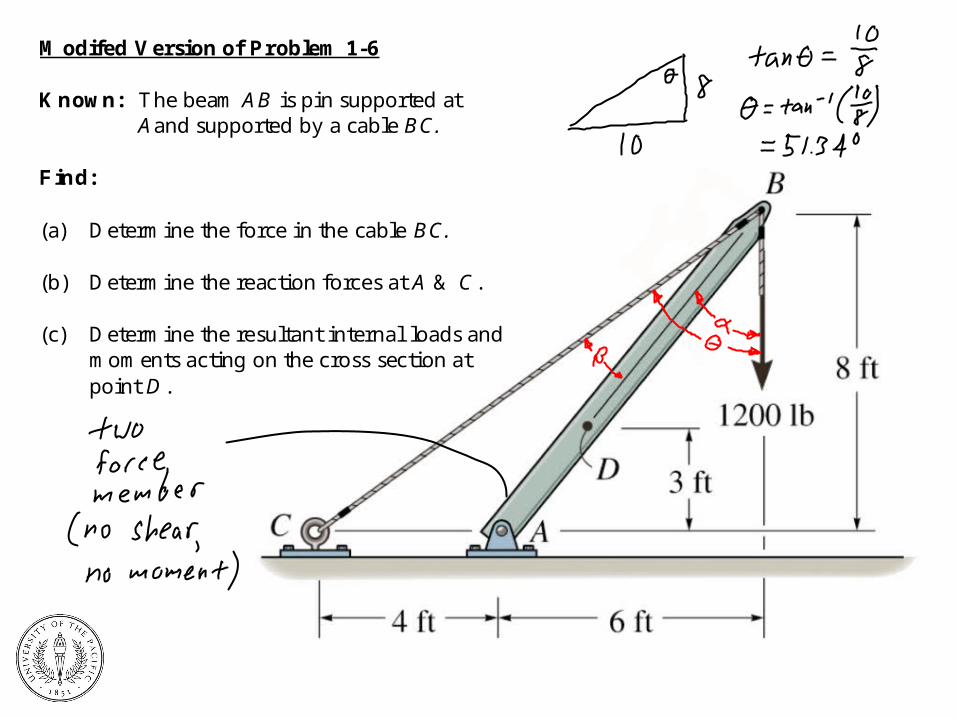
Modifed Version of Problem 1-6
Known: The beam AB is pin supported atAand supported by a cable BC.
Find:
(a) Determine the force in the cable BC.
(b) Determine the reaction forces at A & C.
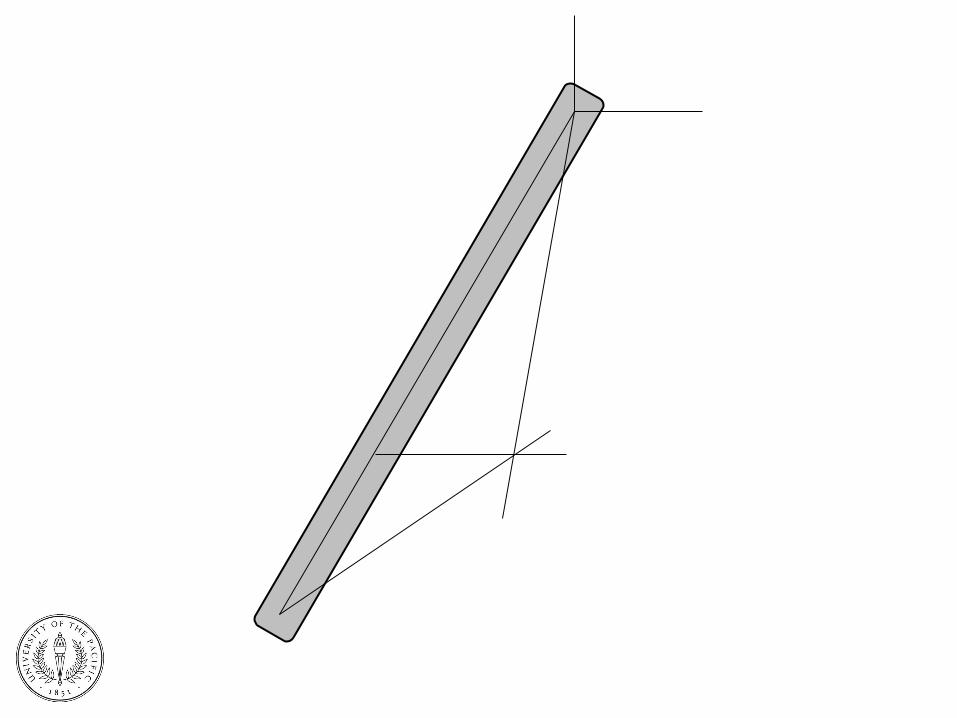
(c) Determine the resultant internal loads andmoments acting on the cross section atpoint D.
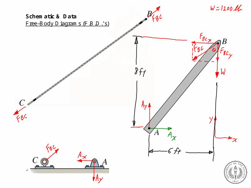
Schematic & DataFree-Body Diagrams (F.B.D.’s)
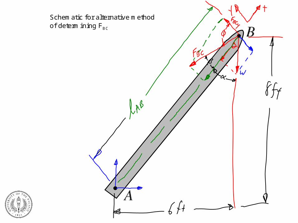
Schematic for alternative methodof determining FBC
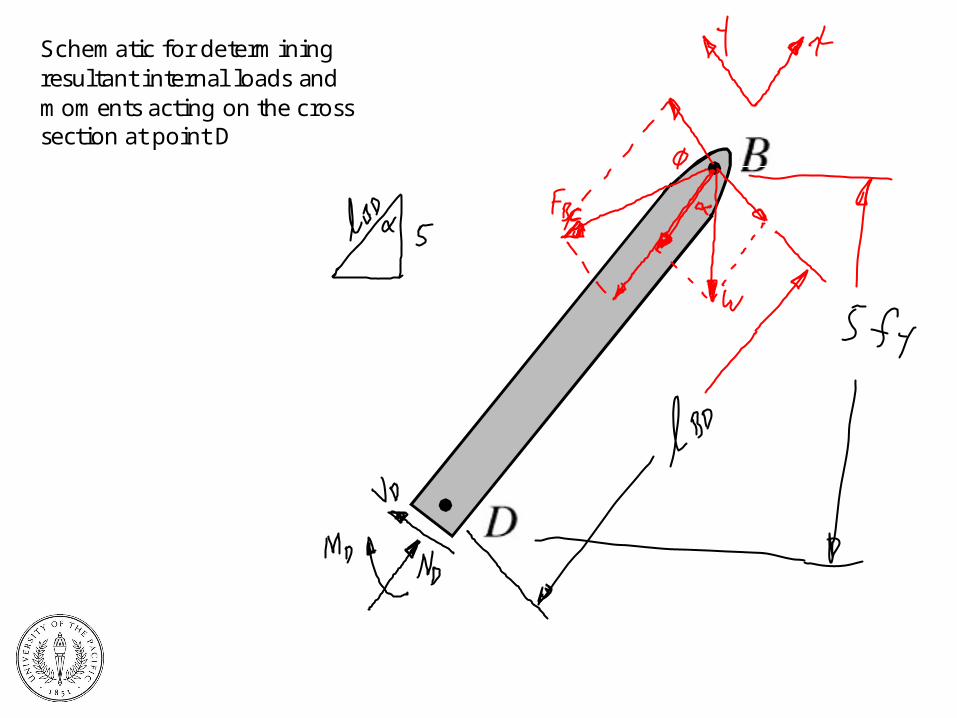
Schematic for determiningresultant internal loads andmoments acting on the crosssection at point D
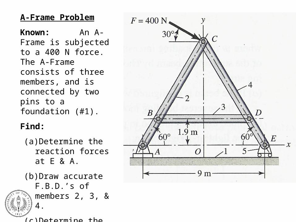
A-Frame Problem
Known: An A-Frame is subjected to a 400 N force. The A-Frame consists of three members, and is connected by two pins to a foundation (#1).
Find:
(a) Determine the reaction forces at E & A.
(b) Draw accurate F.B.D.’s of members 2, 3, & 4.
(c) Determine the magnitude and direction of all forces acting on members 2, 3, & 4.